unclassified - apps.dtic.mil · vt eli eto 3.5 that best results vil hob obtainod on n-teal alas...
TRANSCRIPT

UNCLASSIFIED
AD
DEFENSE DOCUMENTATION CENTERFOR
SCIENTIFIC AND TECHNICAL INFORMATION
CAMERON STATION. ALEXANDRIA, VIRGINIA
UNCLASSIFIED

NOTICE: When government or other drawings, speci-fications or other data are used for any purposeother than in connection with a definitely relatedgovernment procurement operation, the U. S.Government thereby incurs no responsibility, nor anyobligation whatsoever; and the fact that the Govern-ment may have formulated,, furnished, or in any waysupplied the said drawings, specifications, or otherdata is not to be regarded by implication or other-wise as in any manner licensing the holder or anyother person or corporation, or conveying any rightsor permission to manufacture, use or sell anypatented invention that way in ai way be relatedthereto.
RADC-TDR-63-508
DEVELOPMENT OF ADVANCED MICROWAVECOMPONENTS AND TECHNIQUES - PLANAR
HEXAGONAL FERRITES AND DEVICES.
TECHNICAL DOCUMENTARY REPORT NO. RADC-TDR-63-508
December 1963
Techniques BranchRome Air Development Center
Research and Technology DivisionAir Force Systems Command
Griffiss Air Force Base, New York
li "' Project N%.4506, Task No, 450602
(Prepared under Contract No. A\30(602)-2757 by Sperry MicrowaveEleci-ronics Company, Clearwater, Florida.)
14W New
DDC AVAILABILITY NOTICE
Qualified requesters may obtain copies from the Defense Documentation Center (TISIR),Cameron Station, Alexandria, Va., 22314. Orders will be expedited if placed through thelibrarian or other person designated to request documents from DDC.
Released to Office of Technical Services (OTS)
LEGAL NOTICE
When US Government drawings, specifications, or other data are used for any purposeother than a definitely related government procurement operation, the government therebyincurs no responsibility nor any obligation whatsoever; and the fact that the governmentmay have formulated, furnished, or in any way supplied the said drawings, specifications,or other data is not to be regarded by implication or otherwise, as in any manner licensingthe holder or any other person or corporation, or conveying any rights or permission tomanufacture, use, or sell any patented invention that may in any way be related thereto.
DISPOSITION NOTICE
Do not return this copy. Retain or destroy.

Key dords: Fervites, hexagonal; microwave, advanced components.
St-. es h-vo bon made of t!o -rc,,ar.ction and pro'lcrtios of Y corn ovrcls
uith conociLion a ner Zn2 .0Y, 1!!'1 QZnl. 0 Y Cu 0 5 Znl1 5 Y, and hi0 . 3 C"O0 7 Z1 .-
X-r-iy (liffrCtion -attc-ns ta1:mnon Y connoun.-s with- aluninumw htino for iron
stronglTy i'vw rcate the formation of a cocond phase, rather th:,n a r-'r'acona.nt of
Fo-13 by Al +3 in the Y s-tructure. W4hile densities of greaqt-r than 951 no-rcent
of tio thooretica l value an1 Irene indicos of 0.90 and .,bove have boon- obtaiinoi ,
iinoi',idths rcma~ n soiwhat high, approxima-tely 400 oorstods. Atterrits at nr-oarinf
V convorundc; from to-lotactical r-action of' 1i compounC~s and raw oxides have ro-1oA
fru'.tlo, aa- c' ,it fie t-r-.rturos up to 1,10000 no r-actlon occurs.
Biecansc of tho extronol': n7ood alignmeint -of nica ar nottorials achieved, ox-
porinecnts hanve boon started to oriont ce:bic m:-terials;. initial --ae onincnts with
olycrystallino ,tix iron garne t have boon vcry oncoursu-:ing, -:2 1inc-idtha of
1'l to lb, oersteds ha!vf boon obtained.
Initial invosti7 eti on of the application of' lanar fcri tear to 1.0 'o ztor
strueturfas )r- rrrortcd. Beccauseo of tho small siz es and s!a es o-,f nlanar f-r-*[Va,
no-., avai lable. only I -. i solati on v-lucs are fou-nd, biut i sola.tion r t-e- of so Li -It
as 60 are obta ined.
PUBLICATION REVIEW
This report has been reviewed and is approved. For further technical information onthis project, contact EMATE, JOSEPH M. SCHENNA, X4251
Approved: ~ - -
E-~ SCHENNA0 j4 Engineer
liectron Devices SectionTechniques Branch
Approved: .
ARTHU1_ FROHLICH, ChiefTechniques BranchSurveillance and Control Division
XjiI It Ofiii I .. Si, 5 I - 54 11

TABLE OF CONTENTS
Page1 INTRODUCTION1
2 OBJECT 2
3 PROGRESS OF PROJECT 3
3.1 Material Selection 33.2 Synthesis Techniques 33.3 Measurements 43.4 Results 53.5 Applications Studies 22
4 CON4CLUSIONS 33
5 PROGRA FOR NEXT INTERVAL 34
6 PERSONNEL 35
REFERENCES 36

ADVANCED MICROIAAVE COMPONENTS AND TECI4QUES PLAN'ARHEXAGONAL FERRITES AND DEV ICES
1. I11TRODUCTION
This rc--.ort covcrs -ar' -erformied under Co!1&xocL Af3O(6,-2)-2757 FSC-AO82,
Development of AdIvancel 1iciroiuave Components and Techniques - Planar flexaf-nal
Ferrites and Devicos, for the period from Juo 20, 1963 to September 280, 1963. This
ren)ort escribes and discusses continued prog-ross in the first, or trilphase
of the program and initial experiments on the second, or applications, paa
The results roported show that the materials synthesis efforts havr! pro-
duced materi als of good ceramic qutality with high densities and extre-cly high
alignment factors. In view of those favorable indications it is some~rhat our-
,,rising thait linev'iiths no more narrow than 375 oersteds have boen obt-ine~. At-
temnpts are being made to reconcile tis- data.
r'causa, of the ea:trcenelcy good ali-monnt obtained in planar nsteriel]s, it
vras f-Ut Jus-tified to atteernt orient.-tien of cubic ferrites. Prelimianary, but
vory encou2-ir of results are reported. that could h-lve vory -nificant --racti cal
linport-aeee.
The ilijtial i-*sol;ator structure mcasuroa-cats ra ~orted should be co-ra,*de.rcd
viow of th fact that only -- all s rlof a --'l at erial i e- n uaedcc, and
2. OBJECT
TPhe object of this -rnject Ice to inveatig-to thoors'tica liy :-0d o'x r
v'n~'lv "~ cruav chratarat ccofplzas r eaonlmagn-tic o-,id'0., wit'
.2-is' thei4r a1nnlicztio"1 to ---iro.-rvo deovices and circ'aits.
Particular- eohaisis sh-all be ilsood' on the! Oevolo:-nemnt of a ,;eri-s of
1 nan-r :,agnet~c :ito:as'125 nmntization, an; sotro-p f-eld, 5 1 Alio.,i dtha c,21
.)c c're11ndl (' ove r a range of' vallues suitable-: to ijcro-ave aenplica tion. Efforts
11 "o dir'o-ted1 towrd(s theo utilis ation of theso erls in low frequency
(1.0 0-c to 10 GO) dovicos.
One -oal,. of this -roe.rer- is to dononstrato the c ffetivoneoss ofhognl
nt 4C~tris to 'ards the reduIctio n of m:in: t iIn Jo,! frequenclcy res-onance
ol- tors. A stuily A'll also be ri-do of' tech: i' moe of 1i5agelne saral in
-aicr0 -ve sitc'.os to reduce the exenlswitching id( reqa ,rod andl, for a
wars'tc~ag~'i~l',Lo I cmsetea;itchi,',, og--od.
2

3. RORESS OF PROJECT
3.1. 1 ATERIAL S-LECTIOIJ
Durter- this second quarter of t';e pregrra more complete data- havo boon
obta-ined on materia-l proerties as a function of firing ta mnoreture fo-r a number
of compositions. Five difforsent com-ositions have been studied with ra ther
comploto fi ri-n" curves olitainod for throe of these.
For isola-tor applications it is well known intuitively andi demonstrated
-na. vt eli eto 3.5 that best results vil hob obtainod on n-teal alas having:
the narrowest resonanco llnewidth and the lorecst dielectric loss. The field of
materials suitaible for this applica-tion c-an be n-rrowed dowrn to cor.,ositr'oms near
Ni 3 Ou 7 Z 1 Y Pi1 0 Zn1 Y, or uZn Y. The optimum conruositioes :robnbly- lie
near one of those com-positions.
At this - oint it is net yet clear wl1et material characteristics ara) moot
imnortant for the switching appli cation, and therefore some of the miore i l
anisotrow)ic cenacasitions liI~s C0 2 /Cu/ 1,Zn 2 / 3 Y will continume to be netm:td
The substitution of aluminumi for iron, initia tedl in the last Qua rter,
,mse found to be fr -itloss for controllin-g the magntization of tV- :r-tori al.
X-ray data inflonted that the alum.in s-ubstitution r-aultod in a acoed 'irasc
formation in thenmaterial tha--t adversely affected its mi,0crov- enorris Th:is
famj~ily of mterials h--s therefore boon drooped.
3.2 SYPTUTSIS TECHINIQUES
The a ropara-tic-m -recess used in tis a <earter x.-as o----"lt1 -fly the srec s
that outlieed in tie First ,uw rtor1 -- r -ort. EnacorEL ent:al data obtaine d eOn a vcrrlat-
of sa;.-:-l-las inietotat t a iso~ of ethyl alcohol as the carrier in the attritorieg:
3
ste -e results in betto r r:toriazl nrnperties andt grea:tly- f:rci lit- tes t:'reev
The torotactical reaction technimwe dicuse ;n the last qirterlyr
Report fai].ed to give seT Qficierrtly nacourag-I g results to ,arrnt contin-ance.
Firing temperstor" as hihas l4000 C failed to .rduce, a c0001U51.\'O cenvars(%n of
the 1, compou-nd plus raw oxides to the desired Y structure.
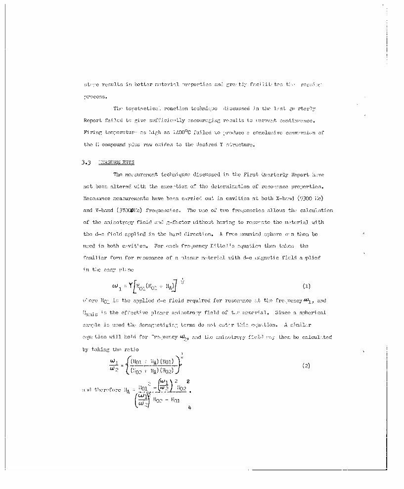
3.3 -:2-ASURE: MNTS
The not suremont techniques discussed in the First Quarterly Report ha ve
sot boon altered with the ex-ce-tion of the deter-mination of resoatonce propeorties.
Resoniance measurements have born carrie 1 out in cavities at both X-ba-nd (9300 1.)
and V-band (37000l'c) frcquc:.cios. The use of tire frequenacies allows the, calculation
of the anisotrepy field m-id "-fr etor without having to resonaIte the maIcterial with
the d-c field applied in the hard direction. A free mounted sphere c' n then be
used in both ca!vities. For each fre1 uency Yittells equation then tacs the
feast] iar form for resonance of a planar mterial writh d-c miagntic field a plicd
-in tile easy -lane
V' ore 11o1 is tile applied d-c f ield required for resonaInce at theC freuacy"L , and
is the ef~ective planar snisotreor field of to. imaterial. Since a spherical
samolJe is usecd the drlcasCotizin tcrms do not eater this:- equation. A s~imila-r
ciu: tien will hold for -rneweacy u4a, and tihe anisotrepy feda"then be calIculatLed
by taking the ratio
[(10101 + "iA) (1101)}(2
U 2 (U 0 2 + IIA) (H0 2 )
2 2
;vnd th~erefore "1A _101 - LWP! Ji02
lo0- - "llp

Thec jvn-~- i e 2c'or f em-- t!-n se c--len, o fro'-u:t: (an y- 0.
r:nnIltn of (2). In t-en c- ICIA]- twIn the- nos. iint~fen ig tcoe t,
In hoe Oenip- m t Me O0-c 'v t c 1il n:'e I -c '':
bJr~ ut the: r-f unoetic field Nrs no dnf~dlc orient-i-n -esi reT-nt to Q7,-
-1"nc. Sic -eu LI n : n rison -n to whethr or not t'-- -en-ur: 10"500< o
vary 'oco orieetoti on of the M- (i-T l Mo. Suche'a onde cc t;omQ' on Tin smec
of the oheorver variain of Itn- idth on o g~iven co: nooftM in. To rcsolve t 12
znietin enlrentn A ' '1mA0 for t;:- o -:ttctr At:h rp 001.100 hot].n
the p.,n anoy -,, r -- t rn-;Te, to tin2 Ki-ne.
;.oansured vnlunn - of Aonsity on' it-notFc cter for fitri-l' T -A
r ]o wn te ce;u a r hoi ce Fi o 1 tr g6. TMo f 'ir -t tr ee, f 5'tr in
cox clt nets Of "oean i Zn/C, the O Cu5211. 5Y, en0" the !hi 3CuL7 Zn3.g(Y
-trcefor h-tclen 7 '- ci olcohel, -o,:tor, and f'yco 45 -ero lined en cc..rnsrs
sIn Q, ottr'tor sU go of the pr-parti-n )roeens. Tijns4, 55 :irw 6 s110 eou l
thougheio'h' loo :o'Tt)e-.I -rtinull: r, the comnponitloosnf
ned CO2y 3 Cu 2 /3 n/ shown in Fiures 5 -od 6 roetv l hvo not jot Wo00 ore-
aired asr lcohol :sr thec sumteir.
Fiim 1- ohIo tiet N- o- ,- ty ofth Ze< co-n o'itin ; not greatly
:ffset"(' b rl' t7 c n' r-,"r YcMl ' -- ;-r e- 2 v-
-'t; cr ti', leo Y 45 c- " V-r 14 - of'7 -m r - ~~
c W or'M a- t-ioM 0 ttic' ^o~i' or- tr'c
-_;_ 'C: (OO"'2%-

1.0
.9
_ __ CARRIERS
.0 ALCOHOL
.7 WATERK IYSO 45
.6
~.4
.3
.2
.15 5 - THEORETICAL DENSITY
U
.4.5J__ _ _ __ __ _ __ _ _ _
4.o- O___11000 11500 12000 12500 13000
FIRING TEMPERATURE (C) 431A
Figure 1. Density and alignment index of Zn2Y samples plotted as a functionof firing temperature. Data are shown for three different carriersused in the attritoring process.
6

REFERENCES
1. B. Lax and K. J. Button, Microwave Ferrites and Ferriinacnetics,McGraw Hill Book Co., Inc., New York, N.Y., 1962, p. 575.
2. I. Bady, IRE Trans MTT-9, 52, (1961).
36
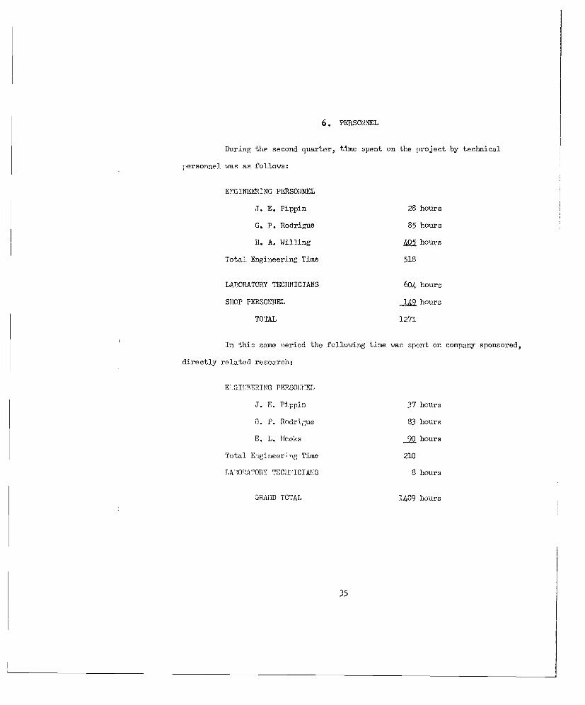
6. PERSONNEL
During the second quarter, time spent on the project by technical
personnel was as follows:
ENGINEERING PERSONNEL
J. E. Pippin 28 hours
G. P. Rodrigue 85 hours
H. A. Willing 405 hours
Total Engineering Time 518
LABORATORY TECHNICIANS 604 hours
SIOP PERSONNEL 149 hours
TOTAL 1271
In this same period the following time was spent on company sponsored,
directly related research:
E GIITEERING PERSONNEL
J. E. Pippin 37 hours
G. P. Rodrigue 83 hours
E. L. Heoks 90 hours
Total Engineer;ng Time 210
LA',ONAPTORY TECH-ICIAS 8 hours
GuAmiD TOTAL 1489 hours
35

densfity that is p6.5 cercent of the th-eoretical O (en--tv. -ho aliga.ncnt fco
data gi~rea at the top of this gra-h showls a nOcc!c dodi-Troveriont in alignment
footer when alcohol is used as the carrier in theC attriter .zta,-e. A fPrior:
tempnerature of 125000C was also found to "'reduce a !laxlmun ali,.2 ient factor of
*'17. This very markedO improve-t'ent in sli.,rnent with, the use of alcehol as thec
carrier has been consistently found for all riate-ri-als nrepared. '11h1lC 12 5000
would be an optimum firing temperaturs for this Zn2Y inaterial as far as density
andI alig-nment are cncerned, the actual firing temperature will he0 influienced
alse for practical m..atorials by the affect of fin opZ teraporz-turCoen dielectric
less tangent. (See Figuras 7 end 8 andl accou,,Iiaoing Uciss&)no.)
Figuire 2 -shews curves ef density a.ndI f-factor for the 0u. 5 Zn-11 5 Y trrs
as a function of fi ring tomparatuire. For this material a s-:bstas tisl i is reve'iot
in alignment is a.-ain notedI on theset sam'"les In 1w.2,ch alcohol was used, n;a the
carrie(r. For this -articular mterial the oaa-,imun density of tlie samr-ns attritrdaodr
with alcohol was reached at a dccidecdly lower firing- tee-er-ture tha:n was th case;(
for samplles erpr~using either wrater or Lyso 45 in the attri-toring tae For
this ma,,teri al n)olyvinyl alcohol. wax i--s aused as a binder with the Lyso 45. Thle
maximum density obtained at 11500C renresnnts -,7 percent ef the theoretical density
ealculted from X-ray data and thec soleeula-r weights of the cea-stituant ions. Thje
alig-nment i ode::. dat.a shewn in th e w rar ercn of thJ a; [:sm hew-o a majximum- vs, Tue
achieved at 120 0 eC or above. An optimum firing- te.mperature mirt lie between 1].500C
an 120Ceeedn;o lc1ee~~ osvr*'_ ,,h t-. -r-tr, . "o
maximum alinne-t for th a' -atonalJ was very nea rly .99 an -:"snses-
s;entially- cenalce. a lignment ef the. gr ins- widthin thai olycr-s4 ",Ili-r a--te-ial.
Similar -'a-,- en the Xi30* 7 n itra -rs'- i -ure, 3. j4
- ter-a1 ''a-s .ot nre:'rn--rd wit; 1.: o Z,5 as eacrriar, hience o"-- ' c- rye for
alcohl- aI,- , n sr oi n f.z-- r--se . e jaxue as' i~e or
7

1.0
.8
.7_CARRIERS
0 ALCOHOLA WATER
KYSO 45 WITHPVA WAX
.4 i
5.5 TH'EORETICAL DENSITY
5.
04,5
4.0 --11000 11500 12000 12500 13000
FIRING TEMPERATURE (eC) 432AFigure 2. Density and alignment index of Cuo.Znl.5Y samples plotted as a
function of firing temperature. Da a are shown for threedifferent carriers used in the attritoring process.
8

1.0
.9
_______CARRIERS
• 7. @WATER78
.6
.5
.4
.3
5. 5
-•THEORETICAL DENSITY
5.0
S4.5
4.011000 11500 12000 12500 13000
FIRING TEMPERATURE (0C) 433AFigure 3. Density of alignment index of Nio.3Cuo. 7ZnI.OY samples plotted
as a function of firing temperature. Data are shown for twodifferent carriers used in the attritoring process.
9

a firing termerature ne:ir 11500C and represents 98 percent of the theoretical
density. The maximum alignment once a-ain occurs for higher firing temperatures -
at 12000C and above. A very marked improvement is noticed in these curves when
alcohol is used in the attritor stage. Once again an optimum firing temperature
should be deternmined by considering the temperature necessary7 to achieve high
density, good alignment, end low dielectric loss.
Figure 4 shows density and alignment indices for three different materials
h.,ving the ben-ic !:i.3Cu. 7 Znl. 0 Y composition with various amounts of aluminum sub-
stituted for the iron. While this substitution was initiated in an attempt to con-
trol t!e magnetization of this material, the effort has been abandoned because of
the results evidenced here. The upper portion of this curve shows that the align-
nent in.dex is great'y deteriorated upon the substitution of aluminum for iron.
Taking, as an example, the firing tenerature of 12500C we find that in two batches
of n terials prepared using alcohol as the carrier, the alignment index drops from
ap'roxt-rtc'y .99 to .7 up-on the substitution of 5 percent aluminum for iron. For
the sane substitution and with the firing temperature of 12000C the alignment index
drops from .90 to less than .2. The observed X-ray diffraction patterns strongly
indete that the aluminum does not actually replace iron in the Y structure but
instead goes into a second phase in the material. Such second phase formation is
evidenced by a drastic decrease in indicated alignment factor. This evidence,
together with th- t obtained on magnetization for these alm.intm substiLuted materials,
was taken as sufficiently conclusive to eliminate such compositions from further
consideration.
Figures 5 and 6 show data tak-en on two further cnmiuositfns that have not
-ret been prsoared using a-cohol as the carrier. In both cases the alignment factor
10

1.0.
.9
.8
.7
.6.-
0 N 0 3 Cu0. 7 Znl. 0 Y.5. 0 Nt 0. 3 Cu 0. 7 Zn1. 0 At0. 2 9 Fe5. 5 1Y
.4 - N10. 3 Cu0 . 7 Znl. 0A1 0 . 5 8 Fe 5 . 22 Y
0, 0 ALCOHOL AS CARRIER
.3 *, A WATER AS CARRIER
.2
5.5
I>4
A020
4.5 _-
4.0.11000 11500 12000 12500 13001 13500
FIRING TEMPERATURE (OC) 434A
Figure 4. Density and alignment plotted as a function of firing temperaturefor Ni0.3Cu0.7Znl.oY compounds in which there has been a partialsubstitution of aluminum for iron. Data are shown for two
different carriers used in the attritoring process.ll

r~i CARRIERS
.6 ____ f ___a 0 ALCOHOLSWATER®KYSO 45
.4
5.21
5.5__
THEORETICAL
DENSITY
5.0
4.50 ____ _ _
4.'11000 11500 12000 12500 13000
FIRING TEMPERATURE CDC) 45
Figure 5.Density and alignment index for Nil.OZnil.oY samples plotted asa function of firing temperature. Data are shown for twodifferent carriers used in the attritoring process.
12

0.5-
0.4
0. 3
0.2
0.1
0.0
5.5THEORETICALDENSITY
u5.0
bD
b.-4rn
4.5
4.011000 11500 12000 12500 13000
FIRING TEMPERATURE (OC) 436AFigure 6. Density and alignment index for Co2/3Cu2/3Zn2/3Y samples
plotted as a function of firing temperature. All data shownwere obtained with Kyso 45 as the carrier in the attritoringprocess#
13

is inferior to the general ruin of materials, and it is expected that considerably
improved results will be obtained when these materials are prepared with the alcohol
carrier.
Data on dielectric loss tangent as a function of firing temperature for
the Zn 2 .oY material aro shown in Figr-s 7 and 8. Three comositions with different
iron content were triod. The starting copoitions of thse three compounds were
varied from approximately 3 percent iron deficient (5.8 Fe) to approximately 6-1/2
percent iron deficient (5.6 Fe), to 10 percent iron deficient (5.4 Fe). Figure 7
shows data taken in an X-band cavity on rods of the m4teril 40 rils in diameter,
while Figure 8 represents data tacen on riscs of the nataril at 20 11c using a
Boonton Q raeter. It is felt th:.t for r'ierovxve puroac the X-banO crvity "erturba-
tion measurements are cnasider:ably morp reliable than :ire the Q meter measurements.
In general, the measured data are in r-asnably good agreement. There is a con-
siderable spread in the , meter measurerients, but this i, inherent in the accur:cy
of the measurement. It is seen from both these curves th:'t the dielectric loss
tangent increases rapidly for this material as the firing temperature is raised
above llO0C, and is quite high at 12500C, the optimum firing temperature for both
good alignment and high den:sity. Thus so-e compromiac ust be sought betueen the
loss tangent ano the alignment and density rceirrcnts on firi-ng teirporaturc.
One possible cause for this rai increase in loss tangent with firing
temperature is that zine is being lost on firing at the higher temper t ures, and as a
result the m:.terial has excess iron. It was to correct this possible cause that the iron
Ieficient compositions were synthesized. It is seen particularly clearly in Figure 7
t-st the rediction in iron stoichiomctry does, in fact, reduce the dielectric loss
tinaent in the finsalmaterial. The lowest loss tangent neasured, however, is still
14

0.1- /
A Zn 2 Y (5.8 Fe)
A Zn2Y (5. e Fe)
A Zn 2Y (5.4 Fe)
0.01-11000 11500 12000 12500
FIRING TEMPERATURE (0C) 437AFigure 7. Dielectric loss tangent of Zn2Y samples plotted as a function
of firing temperature. Data shown were obtained by X-bandcavity measurements and represent results obtained on materialsof three different iron stoichiometries.
15

1.0
0 D
0 1
0.1
O Zn 2 Y (5. 8 Fe)
* Zn 2 Y (5.6 Fe)
® Zn 2 Y (5.4 Fe)
11000 11500 12000 12510 13000
FIRING TEMPERATURE ('C) 438AFigure B. Dielectric loss tangent of Zn2Y samples plotted as a function
of firing temperature. Data shown were obtained from Q metermeasurements at 20 Mc and represent results obtained on materialsof three different iron stoichiometries.
16

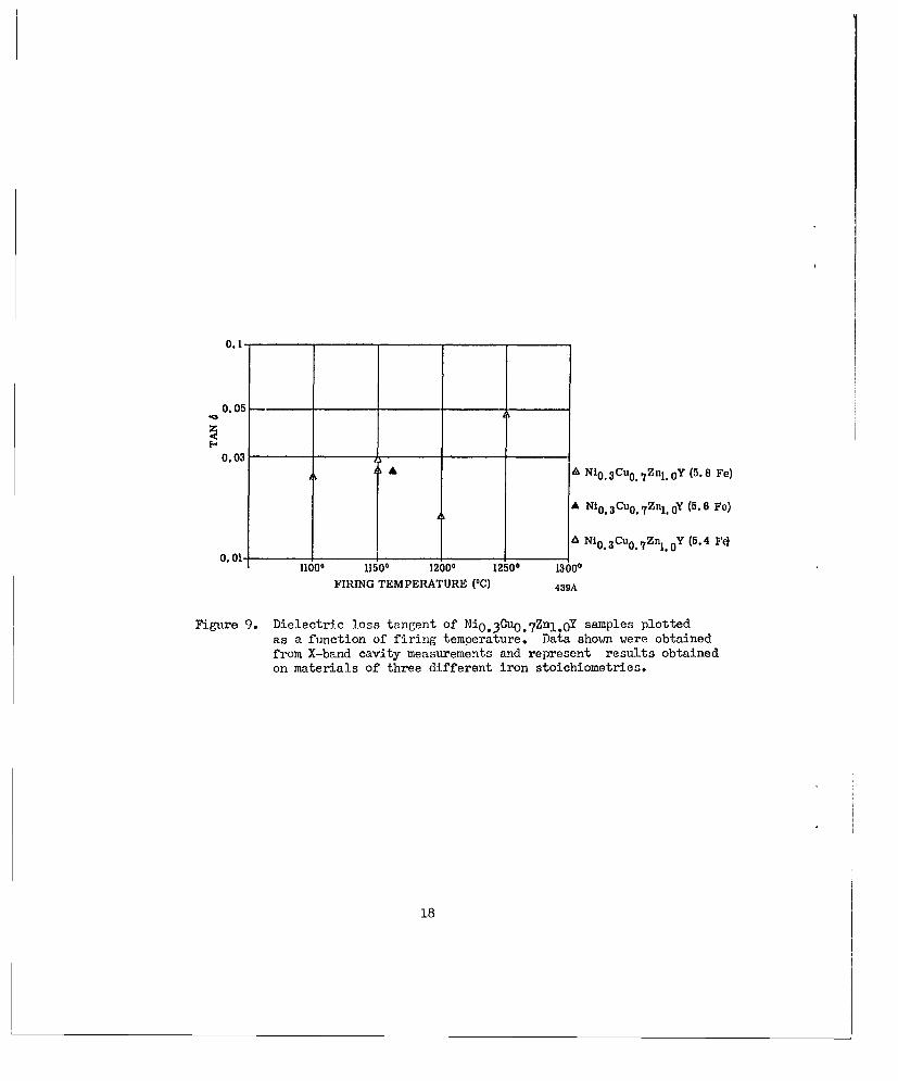
0.011 - a relatively igh value for microwave applications.Figure 9 shows the dielectric loss tongont of the Ni 3Cu.7ZnI.oY compound
as a fu nctien of firing temperature. Data on two compositions of differing iron
stoichiometry are also shown. These data, though not yet complete, indicate that
iron stoichiometry is of little imnortance in determining the dielectric loss of
these materials. These data were all t ken at X-band by cavity perturbation
techniques.
In Figure 10 are shown data taken by both cavity and Q meter methods on
t'e Cu. 5Znl. 5 Y compound.
It should also be noticed that in neither of these materials is there
as strong a tendency for the dielectric loss to increase with increasing firing
temperature as was experienced with the Zn2Y. In fact, the dielectric loss of
these com.ositions rcaain relatively constant as the firing temperature is raised
to 12000. At still higher firing temperatures there is some evidence of an in-
crease in dielectric los s. The relatively flat curve of loss tangent as a function
of firing tem-erature for these materials and the absence of any apparent dependence
on iron stoichiometry both indicate that the loss of zinc is not severe with these
two materials. Again loss tangents of the or0er of .01 to .02 are obtained.
Table I contains a variety of data on scattered, though representative,
samples of planar materials. The data showm here illustrate the results obtained
.n terms of average values as well as departures from the average values. While
some results nay seem Inconsistent from one standnoint or anoti er, they are shown
"ore nevertheless. The various sampl-e wxere preperec with elcohol, Kyso /5 and
water as a carrier in the attritor strge, and were fired at differing firing
temeratures.
The saturation magnetization for the Zn2Y miterial sho,,m in Column 5 of
this table is centered around approaimrtely 2100 gauss with approximately 100
17
0.1
0.05
0.03A A Ni 0 . 3 Cu0 . 7 Znl. 0 Y (5.8 Fe)
A Ni 0. 3 Cu 0 . 7 Znl. 0 Y (5.6 Fe)
0 Ni 0 3 Cu0 . 7 Zn1 . 0Y (5.4 FeO. 01 I
1100 11500 12000 12500 13000
FIRING TEMPERATURE (°C) 439A
Figure 9. Dielectric loss tangent of Ni 0 . 3 Cuo. 7 Znl. 0 Y samples plottedas a function of firing temperature. Data shown were obtainedfrom X-band cavity measurements and represent results obtainedon materials of three different iron stoichiometries.
18

0.4 .
0.1 _
0.05
A X- BAND DATA0 20-MC DATA
0.01
11000 11500 12000 12500 440AFIRING TEMPERATURE .(OC)
Figure 10. Dielectric loss tangent of CuO.5Znl.5Y samples as a functionof firing temperature. Data obtained from both X-band cavitymeasurements and 20 Mc Q meter measurements are 'shown on thisgraph.
19

TABiLE I
1 2 3 4 6 8 1 9 10Sirin gI
No. emperature 4TrMri All i IA29 2 s is
Sa_ple __teral_(°0) Crrier (gauss) F (oe). y _ s) ,
11-29A Zn2.0Y 1150 Alcohol 2180 .817 569 14,650 11,3001'i-294X Zn2.Y 1150 Alcohol 2090 .742 587l -15A Zn2.0Y 150 Kyso 45 2010 .18ITP-15E Zn2.0Y 1200 Kyso 45 I 2180 .48 6 8 3.12 l4,S00
IIP-15C Zn2.0Y 1250 Kyso 45 2220 .605 589 15,000
lIP-lC Zn Y 1250 Water 2200 .347 1--O
IP-20B COU5Zn I 5Y 1100 Alcohol 2260 .70 723
IP-20A Cu* 5Znl 5Y !1150 Alcohol 2320 .85 513 2.6 11,O00 9,400
IIP-20b Cu: 5 Znl*5 Y .1200 Alcohol 2390 .995 496 2.14 21,677 12,400IrP-2O' Ou.5Znl• 5Y :1250 Alcohol 2370 .9831527 1.75 39,700 14,900
IIP-19A Ou 5Znl 5Y 1200 Kysu 45 2260 .66 620 ]2,300IIP-19C Gu:5Zn1 :5Y 1200 Kyso 45 2000 .864 710 2.48 14,100T!P-19E Cu. 5Znl. 5 Y 1250 Kyso 45 2190 .713 682 1.96 18,700 13,6009-A Cu.5Znl.5Y 1250 Water 2290 .792 100D 12,500
HP-21B NI. 3Cu.7 Znl.0 Y 1100 Alcohol 2760 .601 419 .2.61 9,200 8,600IP-21A NI. 3Cu.7Znl.1 Y 1150 Alcohol 2330 j .893 375 2.9 7,/00 7,700.TP-21C ""i.3 Cu.7Znl.0 Y 1200 Alcohol 2550 .984 431 i2.46 13,700 10,700UiP-6A Ni. 3Cu.7Znl•0 Y 1250 Water 2820 .358
HP-21A Ni 3Cu 7 Znl 0 YGA21150 Alcohol 1530 .232.435 7,094 7,213HP-21C Ni: 3 Cu: 7 Znl:0 (55Ak)i1200 Alcohol 1590 .476.400 7,700 7,660
IIP-7D V' 30u 7Znl o U) 1250 Water 2400 .6 070 8,430
Iji-8B 3 C 7 Zn 0 CA 1250 ater 2450 .284-1800 750
up-8A Ili. 30u. 7 Znl.0Y(G 'A 1250 ater 2130 1400 1,000
IHP-9A Pi. 3 0u. 7 Zn1 .OY(15Wi 1250 ater 2490
HP-4 l il.OZnl.0 Y 1250 'later 2390 .863 1000 13,600IP-18 Nil.OZnl.0 Y 1250 Kyso 45 i2450 j .434 680 15,000
Hi-12E C0o2i3 a2/3Zn2/3 1150 i'yso 45 2219 .24
OG-5 3Y2 0 3 •5Fe 2 03 1450 Alcohol 18.3
20

rea:-d is ,ctourod v--lues. o':on L' Cu. 15ZH11 5Y cOuneu1'is ?OtC cto a
:: turati- -a -antztn Oi-:r 2300 (gauss . T- t'-! - casfe thej-roa of Cat-i is
seeuat 'renter, nod eon one sanglo " ve-!_e of only 2000 !005 s a-a eaured,. The
1:1 oXii ,Zn, 1 comeouod h:as- a Oatu-tJon rr raieitie~ln of o roiaey2550gaos
'P]-0 02t1o ti-c olIuiinuq substituted alekel-copper-s ine couni-.ound. show rat'er errati c
results for tho- 5 'erceot aiuniv suibstituted eor-mouid. On the othe~r adno
aigif cotchang e inatciato occurs wl on 10 and 15 -- rccnt alujidnur. is sidl-
stitutod for Aron. X-rnv diffrnct-ion daa trenrly j-dic ted a secon sona
fori:ti en as; evidle-ted here by to ml alig n' .nt factors.
Column 7 of T-bio I 1.as rceasfiurod va-lues of lineoyidth on tl~e different
enceot- er- franctio- of fi-r"'c teni;er-ure cod carrier usedO. It sl~ei'ld be
evr'n'e t frol' t'1 al it t! :nl Miostlsee tan noeisured linowidtl' boors on in-
vorac. relati'on to t'V I rni-gerot iod~lx. !io alignient -seems to heo the cle' f cauise
of 'in -rndo a 'n these ce-m-eiulns -APhsi" 1 n ns -)ros ent. 1narrowest li.ne-
v' lthn -ro obt.-icod on t1he 1:i. 3Cu. 7 Znl1 0 "--te--ol but tha nsen value mecasured
aO ,; :tili] a '-rox.1iiv-tol.y 375 ner:-teds. In vie-z of the extremeily hial; valuies
of "i-oo-t 3 1cea ':C'"Ioved! and. tI.e: relsa.-ively 1;-1gb density of those snueqles it l.a
di ff5 cult to an rtadtlW reason for thisr brood linowidth. Diffe rent cois';eaoitions
1),-h tried i- t'- v'o'-'4 t" of tis-*, cnoooim in order to see 4if a desa-rture from
V : C, re - c 1 frul Id 11 resuljt 1 a a nior- narrow- linewidtb. 11, oddities, efforts
,-1 :i - 'Ce to. (ot~r, - -. 1,tlr or :--t the xxensur-d linouid~tb v- rieso with oriontotion
of I - n-f a-:-t i'.Ya'rdliex idtbs ore fl-mond to vwry b.- -as much as
20C '--ree~t betueen i:eos-urnneants talen on saciales of the same -:7terial at X- and
V-hed ra~ene es lc consIta fin- .,-nc-- do' endcec i;s o-resently note d.
Columns 2, and 10 contaiin g-foctor ad~ a:nisotroniy field d'ata for several
di4fferent ca,;l ositiona. The value s lis;ted in Colum--ns 3 and I 9 r- dedluced from
21
res onaince ne-sre om-nto at X- :-0 V-1h; ad, frsnt :5 -- i-o~d 'n Section 2.3.!-ue
!I isted in Colum,-n 1-0 are co:nnod fro- 1-b-inC on- surcononts olono n !'cr tlr' ;-,3m, -Mon
-t =2 or 'Y -. S. It f:,101110' ho- -oi 4slontt thle eo--,'tat~on:s ±nvolvo, -',
escterrdning theose voluos. U -ttd in Columns 8 nd 9 re ,.Lther sensitive to sm-.all
errors in- 'etn r.-m 1-ning, the fieldl reqi~red for r;-senaune at the tw~o froe-moncies.
-eca-Lse of the- extrene'y g-ood' alig,-nment factors aCCIIeyed on b-annt' :
ff',ort 175carri: ol et on an aseccinter' eeo-uieay-ss.on sore d regina to test these o
otA n('- on cahIic no-terialJs. Listed, zt the bette:, of 'ioI is the ii*no,:ilth de-
ti rninod on a 55 yl saornlo of solycr:'toll1io yttrium iron garnet that a"roe
the(- ori.eei't:-Inn tcneovol-ved in tlI-'s study of loner mter:-1s. TheO
co, -niy Ct b conoicderall y i .-revcd b"- ea;o- differen t fi rin,- ton- -orature.
TI1s0 e "ttimE- a ieudt UOnly 18.3 erts 's ob-tained on t: i.s eolycrystn.-e
-'-oril nt> '-lt~vly l densi'ty is ',-It toh oP' -neicaton of 't !-not
rti-ly seesofl al~nmt n "Cl,-,7 Ce r-I-_e:I of' t1: 4- --'ra Tr;or% -A
-''C,! Cb e o . t ;trls ' -ime rona-tecs -:c.r -ill, -<a' ''n':vo
,)f tlil order to': sC7o Ml - rr:t-isbo c "v" e:U,
Ot- ea i..mortzn t r; ct Cl iliie -tiof, of cr-s;,It, t!' 'ffort 15 h iv cos-
tu Iicd into) t, ", =-t --l rt.-r. 'f 'e revs,-"- si'lo i ories t t- !r s of
cute~ -rat-. f -'rr'to-s nPt'o 1-a-t re- 1--i. reduce t' -Kr 1n-c!aftbo, s i -ri
- -- -nerot'r of Wv-tic Faa:- '"-- 1 ho vel Lole.
3.5 APPLICATIC: S 7-D155
Drnt>- n ,ot -- rtrr ste' hve ons nitieted into the application
1-v tr'-'to -rete Incro-.!,nve devics. Idtial e-fforts av been
eonneentr to' en s-l-b ie o tor configuvrations.
22

5.Ticreuil A1!iyrl -
It is- r' 's XeC 1 b, 1 )t' §t t' c- Urw I.-ol-tion ret' of -ieA! tc
:-t er* il Toe; ted( In v xv-.-l 9e c: -. t b pe-rtvrbe!-t2 e' thor.- r:
'enone 521100 tile thric'rie eei: et-c, not crop r-Ide~c to th-i- e--ntiec0"S
1c"Yzn, co are t ' pto'rite terms of t'e;s crth lit- t -n:;or ci:d
till- -- e- ni:enetac r'iold is ioexeeosplic(I ian tVio y--srectioo . i~ s-ce't i-
lit:-tc tOS- a-) ronristeu to tie '< r12cul -u of1:a r fer t.es one can (1c1 rio
titje o,,tiwf retra c fCi or ti- n :,s .,nilu t' e 1flii-cc of' v reov, lvteri;1l
-Toflrtios o0 tins aexin isolatt'o r-t.io.
The suscce-tbilit" termi e:!- !,c, derive d fro7ji, the Landn.u-Lfshitz eoeratonn
xrhern 1', 11, iodn(' fre ;25 )revin0vis1y 2efin r0 n nO a is the nepro ,riltre factor.;
Fell ~ !Ir od''r1 ~C cr;,.r tion fo" a '11 or 'tvterrlal -ith 'e1s sane 1n the C-.y
-1i oe, ne Pod for tilh g'u' or ]o:;s terms of tCo tenser :roocetibility
= &LL [2c1 + -' 2) ) (5)D
=L ++w+-a: 2 Ii 2:±] (6)
:1', (7)
23
'-2:' D = z(] a2) - 2 + 22 - ' 2.
occura '-t r esancc, that is
2II.' = i:Iz
n f -- ther th:rt
a 2 << 1,
t'- d r atl2 for Fr,,.- becomes
•i -J on___ ,i c e 2 t h s b co r e t h e f : um0 I r r l
20,r
F .ax (9)
The r'1lrtin 'rsh for the -a-fiimun iolat'n ratio indicates that this ratio is in-
-1-r.endent of thc anicotrony fNet,' of the r.aterial.
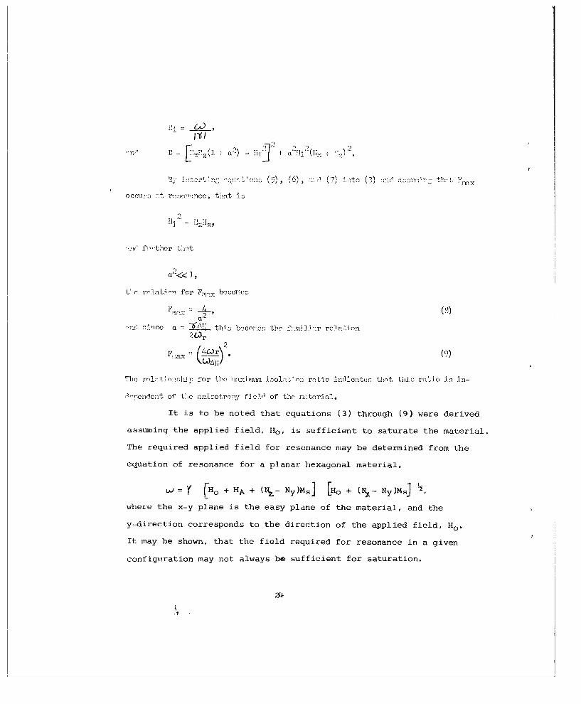
It is to be noted that equations (3) through (9) were derived
assuming the applied field, Ho , is sufficient to saturate the material.
The required applied field for resonance may be determined from the
equation of resonance for a planar hexagonal material,
W.A.= Y [H0 + HA + (IqL- N y)MS] [Ho + (N - Ny)MsJ
where the x-y plane is the easy plane of the material, and the
y-direction corresponds to the direction of the applied field, Ho .
It may be shown, that the field required for resonance in a given
configuration may not always be sufficient for saturation.
24

Consider as typical examples of waveguide geometries those
shown in Figure 11. Assigning parameter values of
HA = 10 x 103 oersteds,
4TrM s = 2.4 x 10³ oersteds,
Y = 2.8 Mc/oersted,
and u = 3 Kmc.
We find the following results for a slab with dimensions .875" x .125"
x .020".
CASE I - for the easy plane parallel to the planeof the slab and the slab normal to thebroadwall of the waveguide, the requiredHo is 400 oersteds.
CASE II - for the easy plane perpendicular to theplane of the slab and the slab normal tothe broadwall Qf the waveguide, the requiredHO is 1600 oersteds.
CASE III- for the easy plane longitudinal to the wave-guide axis and the slab parallel to thebroadwall of the waveguide, the requiredHo is 3700 oersteds.
CASE IV - for the easy plane transverse to the wave-guide axis and the slab parallel to thebroadwall of the waveguide, the requiredHo is 1810 oersteds.
In Cases I and II the demagnetizing field is 336 oersteds
and in Cases III and IV the demagnetizing field is 2020 oersteds.
Thus it is seen that Case III would provide the greatest degree of
saturation; however, it also requires the greatest applied field
for resonance. Isolator measurements during this interim have been
primarily confined to Cases I and III due to the size and shape of
presently available planar material.
25

Ho
CASE 1 CASE 2
x- -
CASE 3 CASE 4 441A
EASY PLANE DENOTED AS THE x-v PLANE
Figure 11. Various possible configurations of a planar material mountedin a rectangular waveguide.
26

b. Measurements on Isolator Configurations
During this second quarter investigations were conducted
to determine the performance of isolators using the best of the
available planar hexagonal materials. The principle aim of this
study was to determine the correlation between theoretical pre-
dictions and experimental results. The material investigated was
Ni. 3Cu. 7 Znl.0 Y. The material was made into slabs and mounted on
the broad wall of both S- and X-band rectangular waveguides and
subsequently inserted in a variable magnetic field. A special
section of waveguide was designed with one broad vall in the form
of a sliding plate, so that the position of the ferrite could be
continuously varied within the waveguide.
A slab of Ni. 3Cu. 7 Znl. 0Y material fired at 1150 C was
mounted on the broad wall of the waveguide as shown in Figure 11, Case
III. The dimensions were .94" x .125" x .032". The response of the
isolator to a varying applied d-c magnetic field at a frequency of
9 Kmc was observed for different positions of the ferrite across
the broad wall of the waveguide. These curves of attenuation
versus applied field are seen in Figure 12. Figure 13 shows
isolation ratios measured at resonance versus the position of the
ferrite across the waveguide. It can be noted that the maximum
isolation ratio is obtained with the slab positioned one quarter
of the broad dimension across the waveguide. Theoretical calcula-
tions 2 show that for maximum isolation ratio for the given material,
the ratio of the magnetic fields, hz, should be 3.78 to 1. Thishx
corresponds to a position across the waveguide of .435 of the
total width at the measurement frequency. The zero db reference
27

P.
o o
0 o
0 ct .1
(Ii H E
Lo- 02 P
C; ______ 0
0 -tO ('d 0
~'~~eq O ~ coto- 4.IC-
~ ~ ) 4 N + I,3E-4 o~~-.a 1/ c
11< 0
_ _ _ _ _ _ _ _ _ _ _ _ _ _ _ _ _ IcaZ.. -n a 1
EIU N NOLVL1MJ..%
284 4

dr-4 0
u 0)
6 *d
0 44
4
or- 0
0)-r
0
W4 ?4C
0 -1 OIJ.V11~ 0 1 j4-'S> D-
pZ9

level for these attenuation curves and isolation ratios was taken
as the output reading obtained with a maximum field applied in the
low loss direction. Hence, any dielectric losses associated with
the slab being measured are not considered in determining these
isolation ratios, and will degrade actual performance. The size
and shape of planar ferrites now available limits the dimensions
of the slabs and restricts isolation values of a single slab to
small values-
The same material was made into a slab of dimensions
.035" x .25" x .875" and mounted in the waveguide in accordance
with Figure 1, Case I. Measurements were carried out at 10 Kmc
and the response of the isolator to the applied field is seen
in Figure 14. Figure 15 shows isolation ratios at resonance
versus the relative position of the ferrite within the waveguide.
Additional isolator measurements were taken at S-band
with larger slab sizes. The isolation ratios obtained were
relatively low and this is believed to be caused by incomplete
saturation of the material. To effectively construct isolators
using these planar materials at the lower frequencies one must
determine a technique of lowering either the anisotropy field,
the 41TMs value, or perhaps both.
30

30 y d 0.05"
I d 0. 075"2'I20 MATERIAL:
Ni 0 .3Cu 0 . 7 Zn1. 0Y
O (j= I0 KMC d 0. 025"
SLAB DIMENSIONS:
x =0.875"z /y =0.25"4 4 z =. 035"
cc + SOLID CURVES10 -- "BROKEN CURVES
0 0
444A 1000 2000 3000
APPLIED FIELD Ho (OERSTEDS)Figure 14. Curves of forward and reverse attenuation measured as a
function of applied field for a slab of Nio.-CUco. 7Znl.oYmat+rials in the configuration of Case 1 of iigure 11. Theparameter in these curves is the position of the slab acrossthe broadwall of the waveguide.
31

MATERIAL
Ni0. 3 Cuo. 7 Zn1 . 0 Y
10 co = 10 1KMCSLAB DIMENSIONS: Y
x O . 875" I :y = 0. 25"z =O. 03 5"
0Z
5
L
0od
0
0.02 0.04 0.06 0.08 0.10 0.12
445A RELATIVE POSITION OF FERRITE IN WAVEGUIDE-I
Figure 15. Measured values of isolation ratio plotted as a function ofthe relative position of the ferrite slab of Figure 14across the broadwall of the maveguide.
32

4. CONCuiSIONs
The preparation )rocess evolved is capable of producing good ceraumic
nateris with hi-h density and g;ood alirnlisnt. T'heso -Atcrials do net as yct
exh&ibit as narrow a linewidth as e-xpected. Comositions near t'.,oac alread~y tried
shiould be check-ed out. Trivalent allioulo-nm subs-tited for tri-valent iJron ap-asren!-tly
fer-.s a second phase material rathecr t1,.an entering1 the Y struicture. A deficieoncy
of iron helps to lower thc dielectric less tangent of ZopY, parhag~s by,, offsetting
the zinc loss on firi-ng,, but th-is aten is not uni ve rsa:lly effective a '0mg the ether
Y coapound a.
Bly usina the aliaymemt techniqu-es developed for these planar mater'le,
cubic ferrita s can bec sueeessflily oriented even in cases of miall. anisotreoy ?t
least partially suceessf':l alio7nqeA has boon achieved em yrttrium iron -arnA -it
anisetreny fields of /4C ecra-tads.
Th1ile initial iaol:'ter me asurements are en ceuiaging, the fa-brication of
pra ctical low fro,,uemeny isolatera will require -,-inerovedC ma-terials in toruef of
linautlth and ,:rgr sized samiple-s.
33

. PROGRAX FOR iEXT INTERVAL
The materials effort for the next quarter will concentrate on the study
of compounds with compositions near Iii. 3 Cu.7Znl.OY, Nil.OZnl.OY, and Cuo. 5 Znl. 5Y in
an effort to obtain materials with improved lincwidths. The 'recess nnw iind .erns
adequate to produce materials of good ceramic nuality and alignment. Effort will
be made to nrocure pressing, equipment capable of preparing samples of larger
physical dimensions.
Some studies of oriented cubic materials will be continued as a natural
eatension of the materials effort specified in this contract.
Studies of isolator perfoxmance utilizing planar hexagonal ferritns will
be continued during the next quarter. The configurations with the easy plane trans-
verse to the waveguide axis, Cases II and IV of Figure 11, will be investigated and
com-nred to Cases I and III. The results obtained empirically and that expected
throu h theoretical nr-dictians will be analyzed. A final analysis of some of the
iteherent advantages or disadvantages of each of the configurations will be made.
The features of using the planar hexagonal materials in a coaxial structure
..ll )e analyzed and measurements of isolator performance within these internal mag-
net str- cturcs will be made. However, in considering a configuration for proposed
isolator design, the feature of high power handling capabilities will be of primary
considern ticn.
The utilization of dielectric materials for optimizing the performance of
isolators emn]oyiaig the planar hexagonal materials will be investi-ated, also the
degree of degradation of isolator performance produced by the dielectric losses
within the planar materials ill be determ iined.
During the next interim the analysis and development of a microwave switch
operated by the planar -meoagonal mterials will commence.

UNCLASSI FIED
UJNCLASSIFHED