unclassified - apps.dtic.mil · et la stability statique et dynamique des corps de rentrle du type...
TRANSCRIPT

UNCLASSIFIED
AD 4 4 6 16 9
DEFENSE DOCUMENTATION CENTER FOR
SCIENTIFIC AND TECHNICAL INFORMATION
CAMERON STATION, AEXANDRIA. VIRGINIA
UNCLASSIFIED

NOTICE: When government or other drawings, speci- fications or other data are used for any purpose other them in connection with a definitely related government procurement operation, the U. S. Government thereby incurs no responsibility, nor any obligation whatsoever; and the fact that the Govern- ment may have formulated, furnished, or in any way supplied the said drawings, specifications, or other data is not to be regarded by implication or other- wise as in any manner licensing the holder or any other person or corporation, or conveying any rights or permission to manufacture, use or sell, any patented invention that may in any way be related thereto.
O Q-
REPORT 347
ul ADVISORY GROUP FOR AERONAUTICAL RESEARCH AND DEVELOPMENT
V N
P
>
,
::-iJ
■ !»■"
64 RUE DE VARENNE, PARIS VII
APRIL 1961
STATIC AND DYNAMIC STABILITY
OF BLUNT BODIES
by
H. C DUBOSE
REPORT 347
NORTH ATLANTIC TREATY ORGANISATION
kt^F^^f
REPORT 347
NORTH ATLANTIC TREATY ORGANIZATION
ADVISORY GROUP FOR AERONAUTICAL RESEARCH AND DEVELOPMENT ' • AlJ
(f i ■ ■ J.
/ & ) STATIC AND DYNAMIC STABILITY C^_^-^/ OP BLUNT BODIES V
./ by
H.C. DuBose .
This Report is one in the Series 334-374, inclusive, presenting papers, with dis- cussions, given at the AGARD Specialists' Meeting on 'Stability and Control' , Training Center for Experimental Aerodynamics, Rhode-Saint-Genfese, Belgium, 10-14 April 1961.
sponsored Jointly by the AGARD Fluid Dynamics and Flight Mechanics Panels
SUMMARY
-^A descrip;ion ia givan of the relationships between the flow fields and the static and dynamic stability of blunte'd-cone-cylinder-flare type re-entry bodies at Mach numbers from 0.7 to 5.0. Effects of variations in some of the shape parameters on the dynamic stability are presented. It is shown that certain combinations of cone and flare angles result in instability in the transonic range. Also, comparison is made between free and forced oscillation data
Une description est donnee des rapports entre les champs d'ecoulement et la stability statique et dynamique des corps de rentrle du type ä cone ^mouss^-cylindre-renflement aux nombres de Mach compris entre 0,7 et 5. L' influence sur la stabilite dynamique de variations de certains des parametres de forme est expos^e. II est d^montre que certaines combin- aisons des angles de cone et de renflement provoquent 1' instabilite dans la gamme des vitesses transsoniques. En plus, les resultats d'essais effectues avec des oscillations libres sont compares ä ceux obtenus avec des oscillations forcees.
533.6.013.4:533.696
3c6e7:3b3g2
ii

SUMIHARY
LIST OF FIGURES
NOTATION
1. INTRODUCTION
2. APPARATUS 2.1 Wind Tunnel: 2.2 Balances
3. TESTS AND RESULTS 3.1 Flow Characteristics 3.2 Static Stability 3.3 Dynamic Stability
4. CONCLUSIONS
REFERENCES
FIGURES
DISCUSSION
ADDENDUM: Complete List of Papers In Serl
DISTRIBUTION
CONTENTS
es
ill
Page
11
Iv
1 1 1
2 2 2 4
A-l
Fig. 1
Fig. 2
Fig. 3
Fig. 4
Fig. 5
LIST OF FIGURES
Dynamic support, propulsion wind tunnel
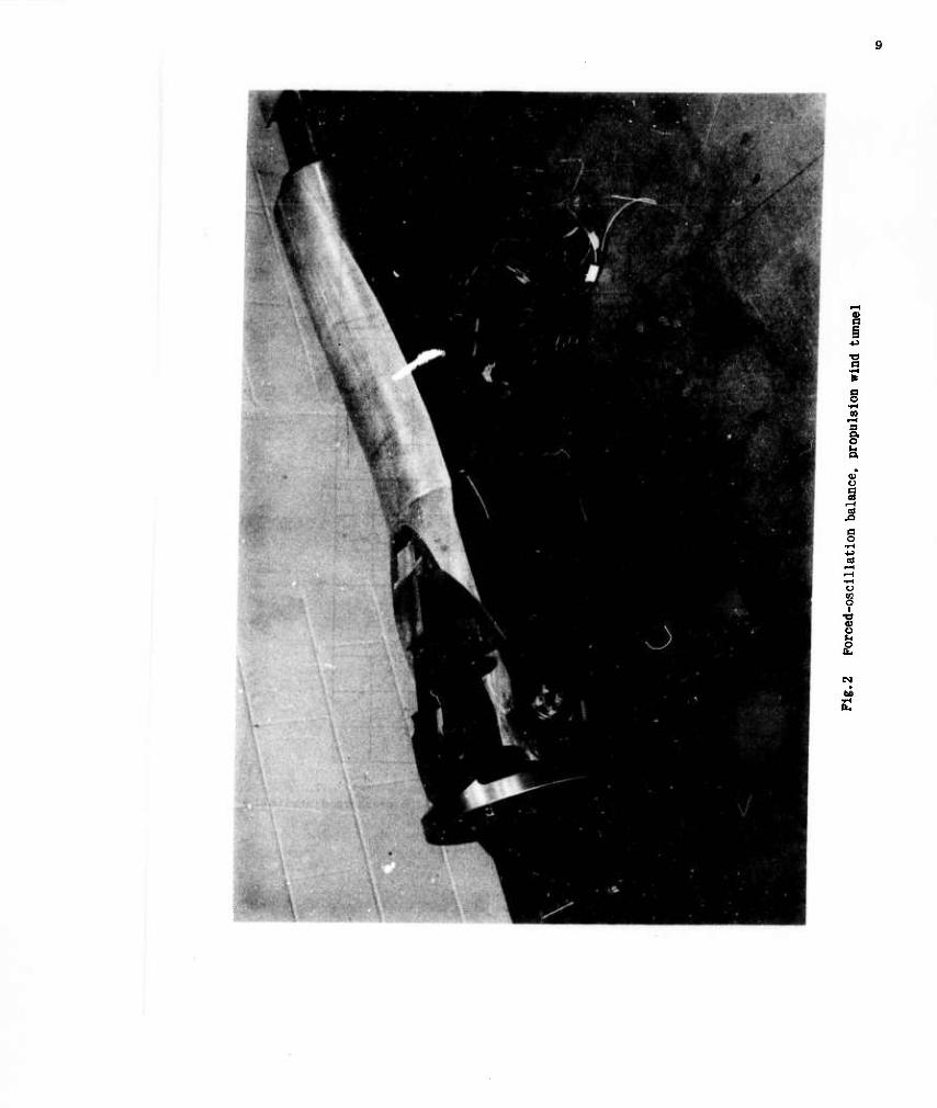
Forced-oscillation balance, propulsion wind tunnel
Typical blunted-cone-cylinder-flare configuration with
pressure distribution
Schlieren photographs of flow field
Effect of Mach number on variation of pitching moment coefficient
with angle of attack
Page
8
9
10
11
12
14
14
15
Fig. 6 Effect of Reynolds number and surface roughness on neutral ^
point location
Pig. 7 Typical variation of C^ with Mach number
Fig. 8 Typical variation of C^ + C^ with Mach number
Fig. 9 Effect of oscillation amplitude on Cn^ + Cm&
Fig.10 Effect of Reynolds number on variation of Cm^ + Cm4 with ^
Mach number
Fig.11 Transonic dynamic stability boundary for typical blunted-cone- ^ cylinder-flare configurations
Fig.12 Effect of Reynolds number on flow pattern at M» = 2.5
Pig.13 Effect of centerbody length on variation of C^ + Cma with ^
Mach number
Pig.14 Effect of flare length on variation of Cm4 + C.., with Mach number 19
Fig.15 Variation of C^ + Cm4 with body length according to Newtonian ^
impact theory
„* n ■ + r values from free-oscillation and Pig.16 Comparison of Cm^ + CB4 vaiuea XJU ^ forced-oscillation tests
Pig. 17 Comparison of limit cycle amplitudes from ^^f^fJ^" 21 with amplitudes for zero damping from forced-oscillation tests
iv
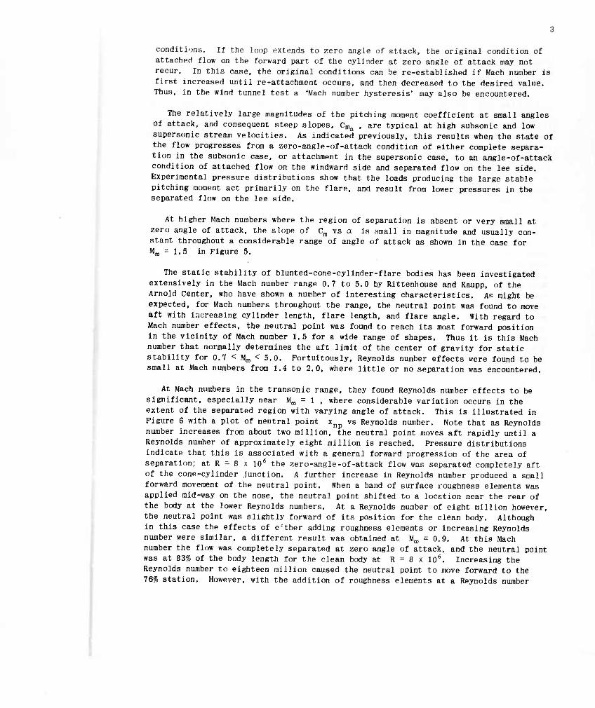
NOTATION
M pitching moment about designated moment reference, ft-lbs
C,,, pitching-moment coefficient (= 4M/qC077D3)
Cma static stability parameter (- dC /da per rad) m'
cia'f) + Cm& dynamic stability parameter:
m ir per rad
3(^0/aV„) 3(dD/2Vw)
D model centerbody diameter, ft
M-, free-stream Mach number
Poo free-stream static pressure, lb/in.2
Qa, free-stream dynamic pressure (- 0.7 PooMo,2 lb/in.2)
R Reynolds number based on model length (= V^,//^)
I model length, ft
V,,, free-stream velocity, ft/sec
a angle of attack, deg
a amplitude of forced oscillations, deg
alim limit-cycle amplitude, deg
ä rate of change of angle of attack (= da/dt rad/sec)
0 angle of pitch relative to tunnel centerline, rad
5 rate of change of pitch angle (= d(9/dt rad/sec)
v^ free-stream kinematic viscosity, it2/«
x neutral point location, positive aft of model nose, ft
t time, seconds
a; circular frequency of oscillation, rad/sec
L centerbody length in centerbody diameters

Lt flare length in centerbody diameters
0n forebody half-angle, deg
#£ flare angle, deg
vi
STATIC AND DYNAMIC STABILITY OF BLUNT BODIES
H.C. DuBose*
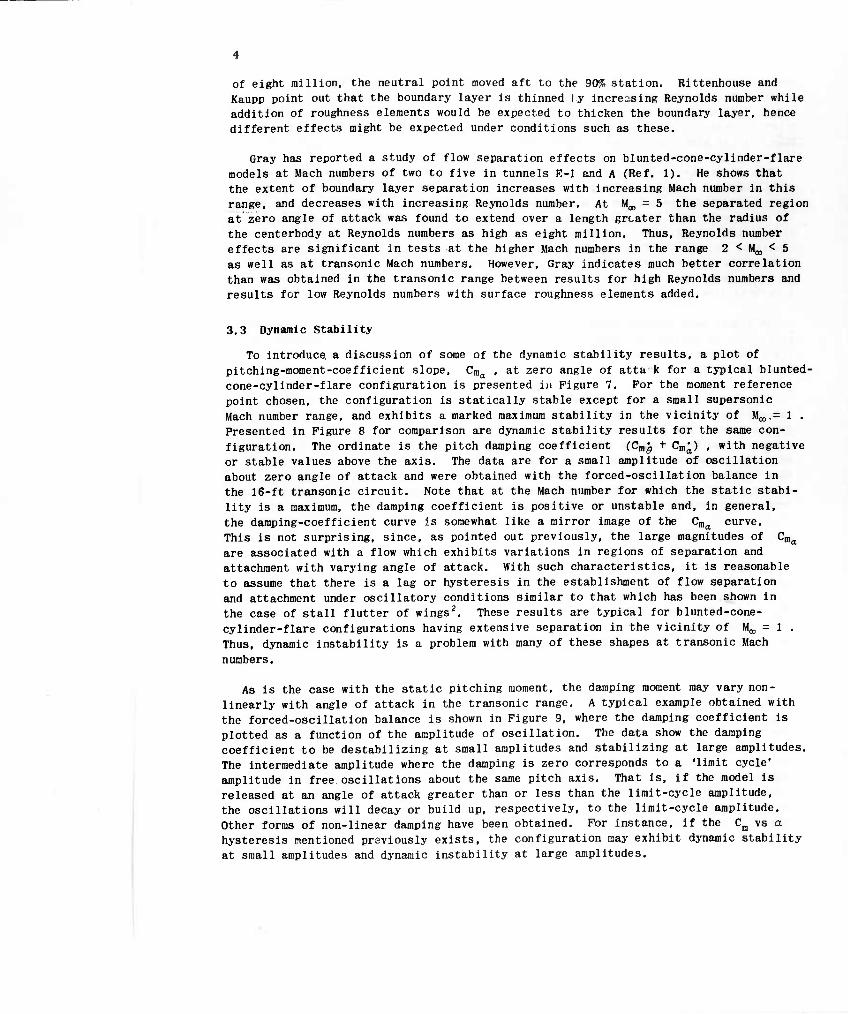
1. INTRODUCTION
Solutions of the heating and stability problems of atmospheric re-entry together with the problems of packaging useful loads for re-entry flight, have produced a variety of unique blunt-body shapes, all of which were of little or no interest to aerodynamicists a decade ago. Although many of these shapes are geometrically very simple analytical methods for predicting their aerodynamic characteristics have been
somewhat inadequate and. as a result, extensive testing has been given them m wind
tunnels and in free flight.
One family of re-entry bodies which has received considerable attention recently is the blunted-cone-cylinder-flare type. These shapes are particularly well suited for certain applications due to their desirable characteristics at hypersonic speeds. How- ever as will be seen, their low supersonic and transonic characteristics require care- ful evaluation. It is the purpose of this paper to point out certain general observa-
tions concerning the static and dynamic stability of this family of shapes.
2. APPARATUS
2.1 Wind Tunnels
The results presented were obtained from tests in the 1-ft transonic tunnel the 1-ft supersonic tunnel and the 16-ft transonic circuit of the Propulsion Wind Tunnel Facility, and in tunnel E-l and tunnel A of the von Kärman Gas Dynamics Facility.
2.2 Balances
Conventional internal strain-gage balances were used, for the static tests; for the dynamic tests, both free and forced pitching oscillation type balances were used.
The free-oscillation balances are of the strain-gaged flexure type. Although they range in size from 0.6 inch diameter to 11 inches diameter, the basic design is as shown in Figure 1. The pivot is formed by a vertical flexure in the center and two longitudinal flexures at the sides. A mechanism is provided at the rear of the balance for giving the model an initial angular deflection. The damping is determined from the rate of decay of the amplitude of the pitching oscillations and the static stabi- lity may be determined from a comparison of the wind-on and wind-off frequencies.
The forced oscillation balance (Pig. 2) is used in the 16-ft transonic circuit to provide more complete data in cases where the aerodynamic damping is negative or non- linear The design was based on an earlier one by the Ames Laboratory of the N.A.S.A.
'Supervisor. Dynamic Projects Section. Arnold Center Propulston HW Tunnel Facility. Arnold Air Force Station. Tennessee, U.S.A.

The model is attached to the disc-shaped face of the forward unit which is a strain- gaged balance designed to measure the moment about the pitching axis. The pivot is of the ball-bearing type and the oscillations are controlled by means of an hydraulic actuator, A leaf spring extending through the front face of the balance is strain gaged for angular position read-out. An analog system is provided to resolve the measured moment into two components: one in phase with position and one in quadrature to the position.
3, TESTS AND RESULTS
3,1 Flow Characteristics
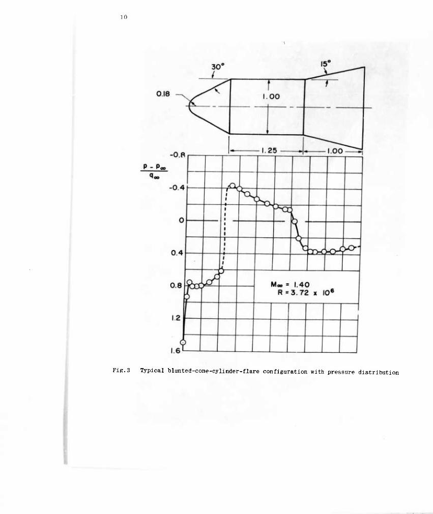
A blunted-cone-cylinder-flare shape having relative dimensions typical of those to be discussed is shown in Figure 3, Some general comments can be made about the flow over such a body. The pressure distribution for zero angle of attack over a consider- able range of Mach numbers, subsonic, transonic and supersonic, is similar to that shown at the bottom of the figure. Prom a stagnation point at the nose, the flow ex- pands initially over the cone and then sharply at the corner where the cone and cylin- der intersect. This is followed by a relatively gradual compression along the cylinder with additional compression occurring due to the concave junction of the cylinder and flare. It is over the length of the cylinder in the region of adverse pressure gradients that under certain conditions flow separation can occur, introducing problems of con- siderable importance,
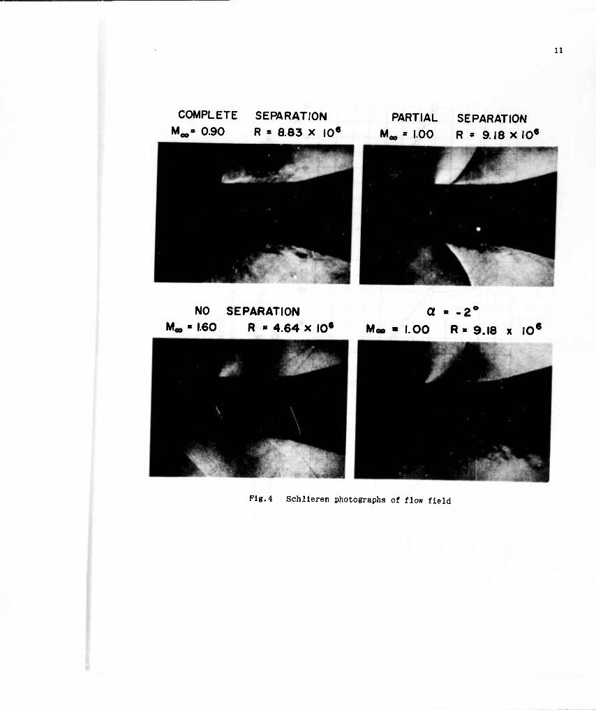
A set of schlieren photographs is presented in Figure 4 to show the nature of the separation. Note that at high subsonic Mach number the flow is separated over the entire cylinder and flare at zero angle of attack. At Mach number one, the flow has become attached around the corner at the cone-cylinder junction and over a small dis- tance along the cylinder. As Mach number Is further increased, the separation point moves farther aft along the cylinder and the flow is attached on the flare. For a given Mach number, the effect of angle of attack is to shift the separation point for- ward on the lee side of the body and aft on the windward side as shown in Figure 4 for a = -2° and M,,, = 1 ,
3.2 Static Stability
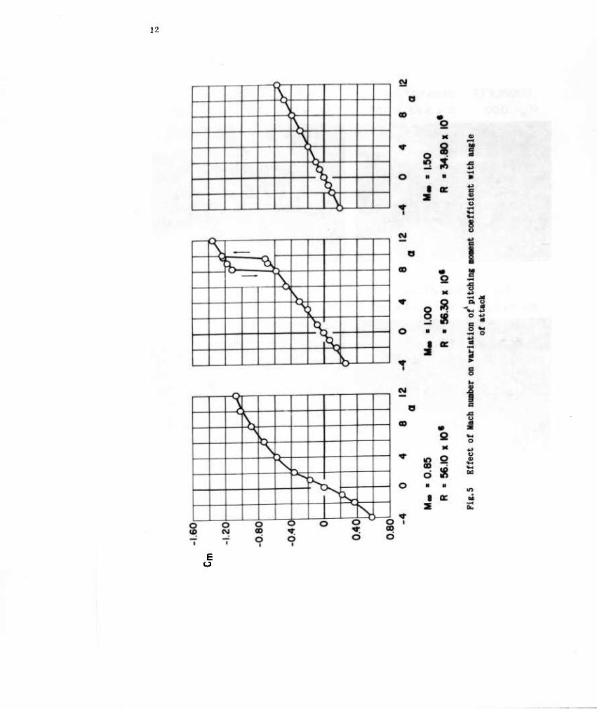
Some results, selected to show the range of consequences of these flow phenomena, are presented in Figure 5, where the static pitching moment coefficient, C , is given as a function of angle of attack. For M^ = 0.85, with completely separated flow at zero angle of attack, the slope is high where the region of separation decreases in extent on the windward side as a increases. For M^ = 1 where the zero angle of attack flow is attached over a small distance along the cylinder, the Cm vs a slope is initially less. However, as the angle of attack is increased, a point is reached at which the separation point on the lee side moves abruptly forward to the corner at the cone cylinder junction. This is accompanied by a sharp rise in the magnitude of Cm. When angle of attack is decreased from this point, a considerable angle may be traversed with the lee surface remaining completely separated aft of the corner. Re- attachment is then accompanied by a relatively sharp drop in the magnitude of C , Thus a hysteresis loop is formed. The angle-of-attack extent of the hysteresis loop may be negligible or large depending upon the model configuration and free-stream
conditions. If the loop extends to zero angle of attack, the original condition of attached flow on the forward part of the cylinder at zero angle of attack may not recur. In this case, the original conditions can be re-established if Mach number is first increased until re-attachment occurs, and then decreased to the desired value. Thus, in the wind tunnel test a 'Mach number hysteresis' may also be encountered.
The relatively large magnitudes of the pitching moment coefficient at small angles of attack, and consequent steep slopes, Cma , are typical at high subsonic and low supersonic stream velocities. As indicated previously, this results when the state of the flow progresses from a zero-angle-of-attack condition of either complete separa- tion in the subsonic case, or attachment in the supersonic case, to an angle-of-attack condition of attached flow on the windward side and separated flow on the lee side. Experimental pressure distributions show that the loads producing the large stable pitching moment act primarily on the flare, and result from lower pressures in the separated flow on the lee side.
At higher Mach numbers where the region of separation is absent or very small at zero angle of attack, the slope of Ca vs a is small in magnitude and usually con- stant throughout a considerable range of angle of attack as shown in the case for Mg, = l.S in Figure 5.
The static stability of blunted-cone-cylinder-flare bodies has been investigated extensively in the Mach number range 0.7 to 5.0 by Rittenhouse and Kaupp, of the Arnold Center, who have shown a number of interesting characteristics. As might be expected, for Mach numbers throughout the range, the neutral point was found to move aft with iuureasing cylinder length, flare length, and flare angle. With regard to Mach number effects, the neutral point was found to reach its most forward position in the vicinity of Mach number 1.5 for a wide range of shapes. Thus it is this Mach number that normally determines the aft limit of the center of gravity for static stability for 0.7 < M^, < 5.0. Fortuitously, Reynolds number effects were found to be small at Mach numbers from 1.4 to 2.0, where little or no separation was encountered.
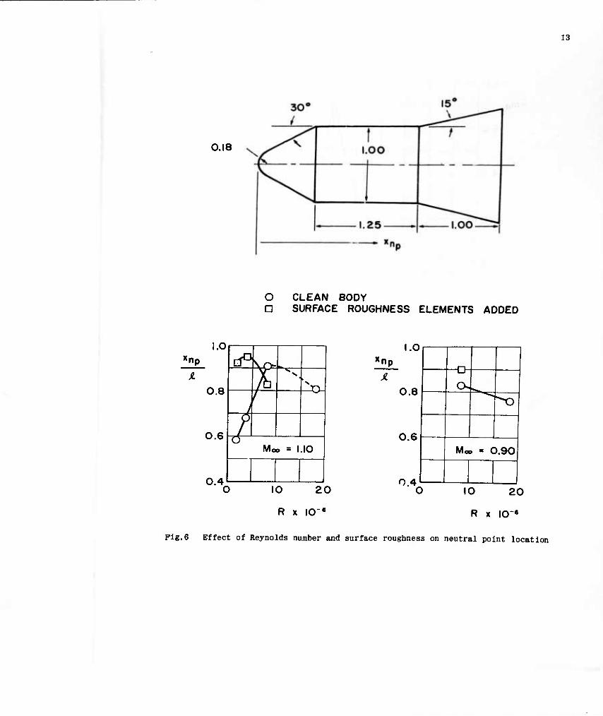
At Mach numbers in the transonic range, they found Reynolds number effects to be significant, especially near M,,, - 1 , where considerable variation occurs in the extent of the separated region with varying angle of attack. This is Illustrated in Figure 6 with a plot of neutral point xnp vs Reynolds number. Note that as Reynolds number increases from about two million, the neutral point moves aft rapidly until a Reynolds number of approximately eight million is reached. Pressure distributions indicate that this Is associated with a general forward progression of the area of separation; at R - 8 x 10⁶ the zero-angle-of-attack flow was separated completely aft of the cone-cylinder .junction. A further increase in Reynolds number produced a small forward movement of the neutral point. When a band of surface roughness elements was applied mid-way on the nose, the neutral point shifted to a location near the rear of the body at the lower Reynolds numbers. At a Reynolds number of eight million however, the neutral point was slightly forward of its position for the clean body. Although in this case the effects of e-ther adding roughness elements or increasing Reynolds number were similar, a different result was obtained at M^ = 0.9. At this Mach number the flow was completely separated at zero angle of attack, and the neutral point was at 83% of the body length for the clean body at R = 8 x 10⁶. Increasing the Reynolds number to eighteen million caused the neutral point to move forward to the 76% station. However, with the addition of roughness elements at a Reynolds number
of eight million, the neutral point moved aft to the 90% station. Rlttenhouse and Kaupp point out that the boundary layer Is thinned ly Increasing Reynolds number while addition of roughness elements would be expected to thicken the boundary layer, hence different effects might be expected under conditions such as these.
Gray has reported a study of flow separation effects on blunted-cone-cyllnder-flare models at Mach numbers of two to five in tunnels E-l and A (Ref. 1). He shows that the extent of boundary layer separation Increases with Increasing Mach number In this range, and decreases with Increasing Reynolds number. At M^ = 5 the separated region at zero angle of attack was found to extend over a length greater than the radius of the centerbody at Reynolds numbers as high as eight million. Thus, Reynolds number effects are significant in tests at the higher Mach numbers In the range 2 < M,,, < 5 as well as at transonic Mach numbers. However, Gray indicates much better correlation than was obtained in the transonic range between results for high Reynolds numbers and results for low Reynolds numbers with surface roughness elements added.
3.3 Dynamic Stability
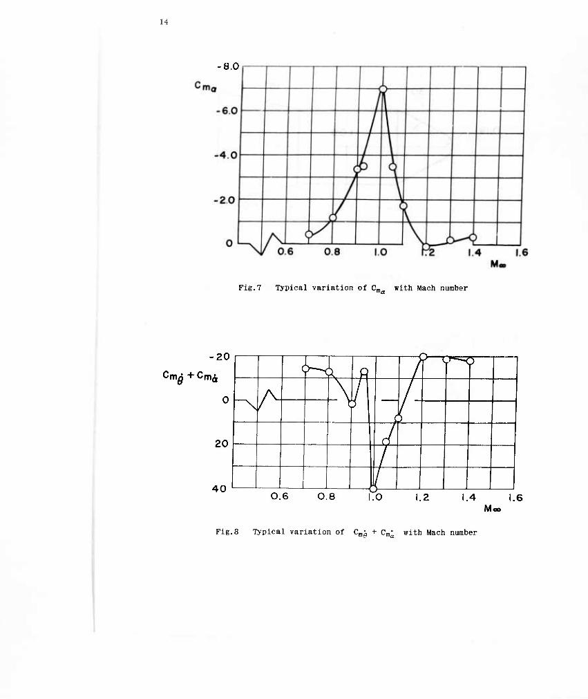
To introduce, a discussion of some of the dynamic stability results, a plot of pltchlng-moment-coefficient slope. Cm , at zero angle of atta k for a typical blunted- cone-cylinder-flare configuration is presented iu Figure 7, For the moment reference point chosen, the configuration is statically stable except for a small supersonic Mach number range, and exhibits a marked maximum stability in the vicinity of M,,,^ 1 . Presented in Figure 8 for comparison are dynamic stability results for the same con- figuration. The ordinate is the pitch damping coefficient (Cm'0 + Cm'a) , with negative or stable values above the axis. The data are for a small amplitude of oscillation about zero angle of attack and were obtained with the forced-oscillation balance in the 16-ft transonic circuit. Note that at the Mach number for which the static stabi- lity is a maximum, the damping coefficient is positive or unstable and, in general, the damping-coefficient curve is somewhat like a mirror image of the Cma curve. This is not surprising, since, as pointed out previously, the large magnitudes of Cnla are associated with a flow which exhibits variations in regions of separation and attachment with varying angle of attack. With such characteristics, it is reasonable to assume that there is a lag or hysteresis in the establishment of flow separation and attachment under oscillatory conditions similar to that which has been shown in the case of stall flutter of wings2. These results are typical for blunted-cone- cylinder-flare configurations having extensive separation in the vicinity of U^ = 1 . Thus, dynamic instability is a problem with many of these shapes at transonic Mach
numbers.
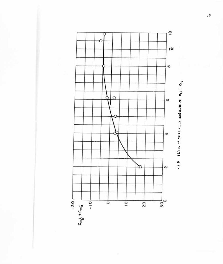
As is the case with the static pitching moment, the damping moment may vary non- linear ly with angle of attack in the transonic range. A typical example obtained with the forced-oscillation balance is shown in Figure 9, where the damping coefficient is plotted as a function of the amplitude of oscillation. The data show the damping coefficient to be destabilizing at small amplitudes and stabilizing at large amplitudes. The intermediate amplitude where the damping is zero corresponds to a 'limit cycle' amplitude in free oscillations about the same pitch axis. That is, if the model is released at an angle of attack greater than or less than the limit-cycle amplitude, the oscillations will decay or build up, respectively, to the limit-cycle amplitude. Other forms of non-linear damping have been obtained. For Instance, if the C,,, vs a hysteresis mentioned previously exists, the configuration may exhibit dynamic stability at small amplitudes and dynamic instability at large amplitudes.
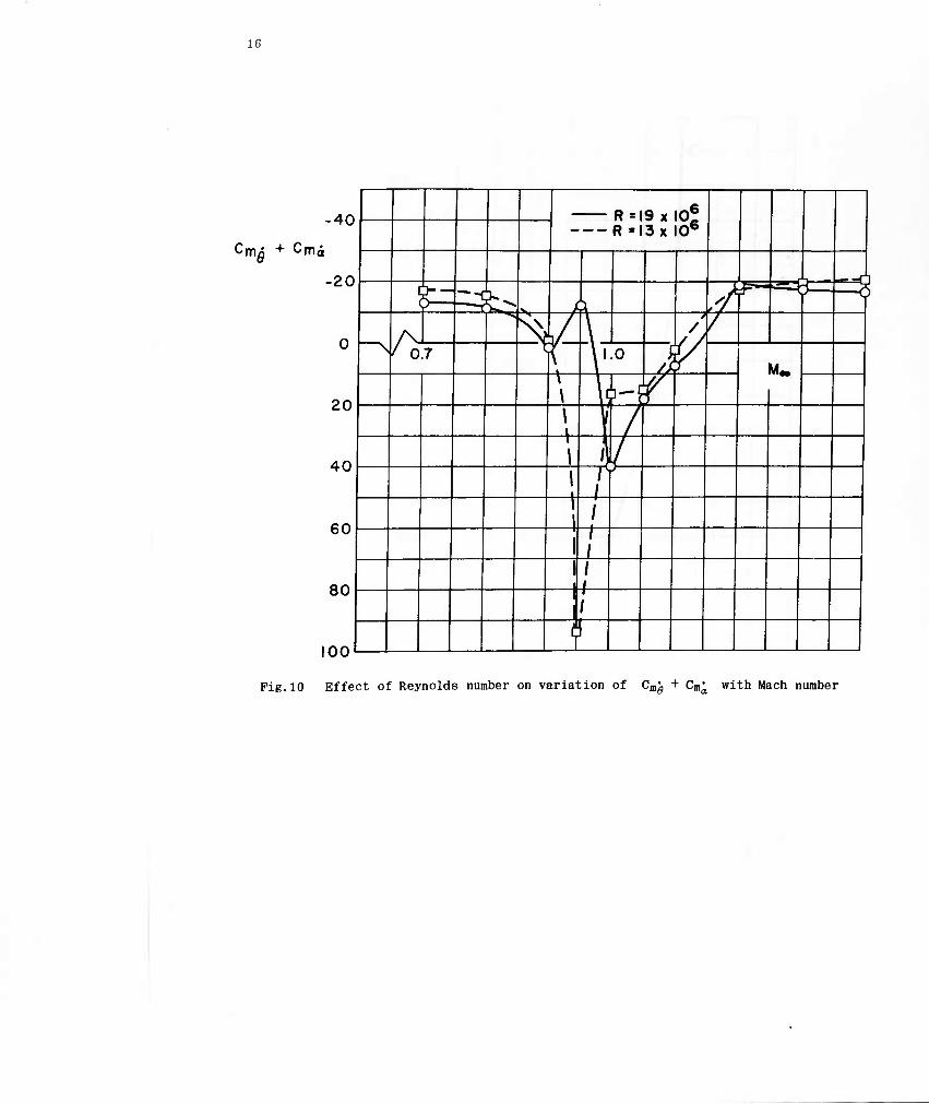
Reynolds number effects on the dynamic stability have been found to be Quite strong In the transonic range. Figure 10 presents a plot of damping coefficient vs Mach num- ber for small amplitude oscillations for a typical model. Note that the variation in Reynolds number changed not only the magnitude but also the sign of the damping coef- ficient at some Mach numbers. Comparison of several shapes at Reynolds numbers from approximately two to twenty million has given results similar to that shown. In general, if a configuration exhibited instability at one Reynolds number in the tran- sonic range, it also exhibited instability at all other Reynolds numbers, although the degree of instability and the Mach number range of instability both varied.
J.A. Black of the Arnold Center has recently completed an investigation of the dynamic stability of blunted-cone-cylinder-flare models of a wide range of shapes at Mach numbers from 0.7 to 3.5. Some of his results showing the relationships between the shape parameters and the dynamic stability are summarized here.
The existence of the transonic dynamic instability was found to depend upon cone angle and flare angle as shown in Figure 11. Flare angle was varied from zero, which is simply an extension of the cylinder, to 15°. For <9n = 10, no instability was obtained in the transonic range. For 15 ^ (9n < 20 the instability could be elimina- ted by reducing the flare angle, however, for 6n %■ 25 , the instability was obtained for all flare angles. Including zero.
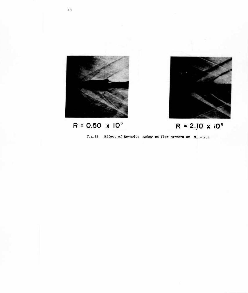
At Mach numbers above and below the range of the transonic instability increasing the flare angle generally produced an increase in the damping. An exception to this was observed at M,,, - 2.5 , at low Reynolds numbers only, where instability of the limit cycle type was encountered. Here as in the transonic case, the effect of increasing flare angle was adverse in the respect that a corresponding increase in the limit cycle amplitude was obtained. Schlieren photographs (Fig. 12) showed the in- stability to be associated with extensive flow separation which disappeared as the Reynolds number was increased. Although the Reynolds numbers at which the instability was obtained were small (0.5 x 10⁶) at this Mach number, the results of Reference 1 with regard to separation seem to indicate that instability might occur at signifi- cantly larger Reynolds numbers at M^ ^- 4 .
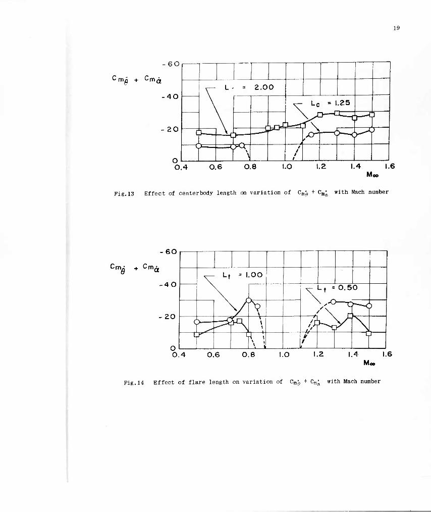
Typical effects of centerbody length on the dynamic stability are shown in Figure 13. For the configuration indicated, increasing the cylinder length produced a general increase in the damping and eliminated the instability. Similar effects are shown in Figure 14 for increasing flare length; however, in this case the instability was reduced but not eliminated. To summarize, the effects of increasing the body length are generally favorable for a given forebody.
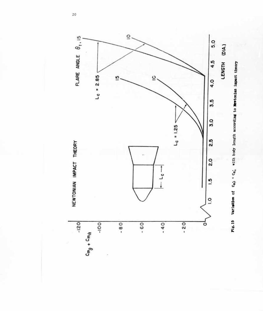
It has been pointed out by Bauer of the Arnold Center that the increase in damping associated with increasing flare angle, centerbody length, and flare length might have been anticipated from Newtonian theory. Newtonian theory predictions for some configurations having a cone half-angle of 15° are shown in Figure 15. The plot shows how the damping coefficient varies as the length of the configuration is increased by addition of various lengths of cylinder and flare to the blunted-cone forebody. The curve starts at a length equal to that of the forebody with the damping coefficient of the forebody. Since the theory accounts for effects of only those parts of the surface that appear in a frontal projection of the configuration, the surface of the cylinder contributes nothing to the damping, and the curve has zero slope over the
6
length of the cylinder. At a length corresponding to the beginning of the flare, the damping increases. Since the Initial rate of increase varies with flare angle, branches of the curve appear for different flare angles, in this Instance 10° and 15°. Each branch for a particular flare angle rises with a slope that continually Increases as the length of the flare increases. The successive branch-points from left to right represent greater lengths of the cylinder. Note that for a given flare angle the initial slope of the branch curve is greater for a greater length of the cylinder. These comparisons are for pivot locations that are a constant distance from the nose. The theory predicts, as might be expected, that the effect of a rearward shift of the pivot location is destabilizing. The trends in the test data agree qualitatively with those shown here so long as no extensive flow separation exists. A significant exception is that the test data show the cylinder to contribute to the damping in such a way that each succeeding branch point should be higher on the plot than the one pre- ceding it on the left.
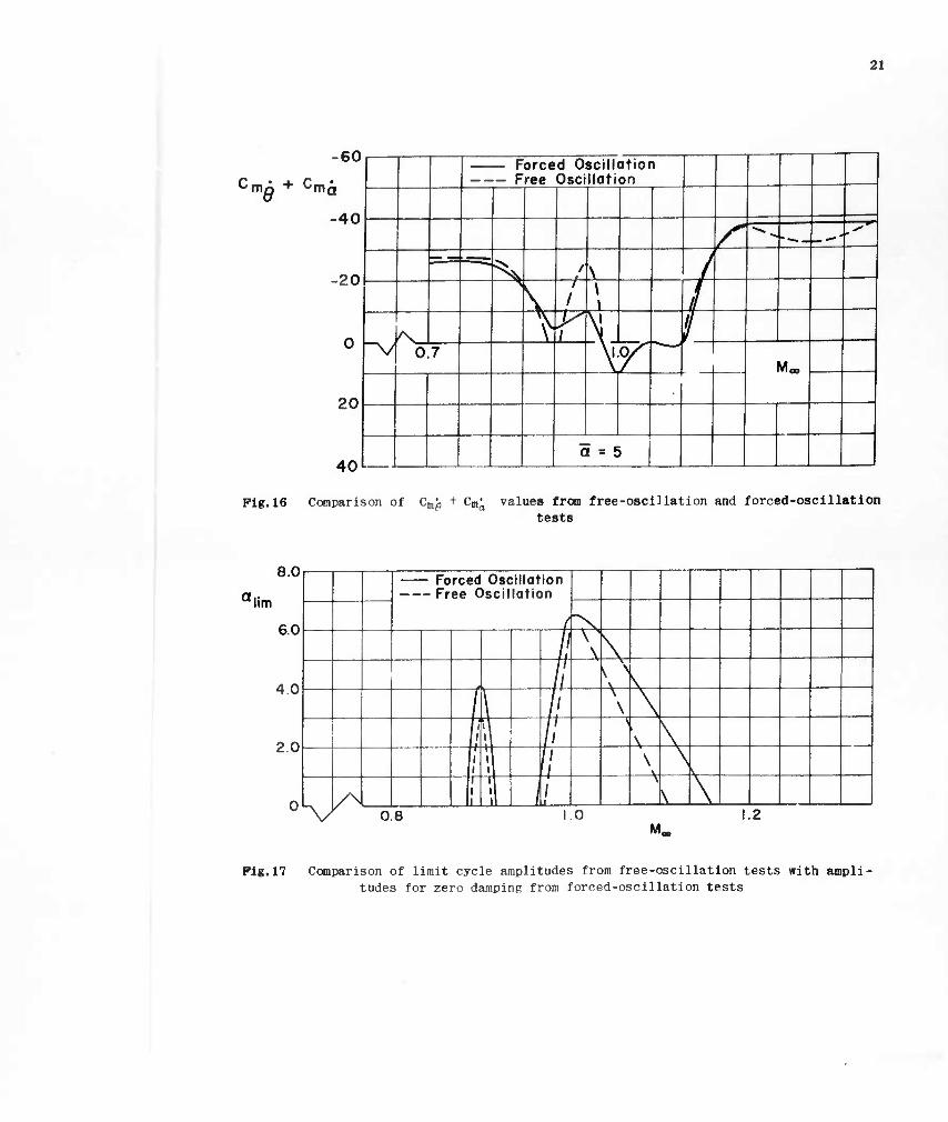
With regard to test techniques, a comparison was made between free and forced oscil- lation damping data and the results are shown in Figure 16. Porced-osclllation data are shown for a range of amplitude from which the free-oscillation data were obtained. The agreement was as good as the repeatability of the free-oscillation data over the Mach number ranges where the configuration was stable. In the unstable range the free oscillation data were in the form of limit cycle amplitudes. These are compared with the forced-oscillation amplitude of zero damping in Figure 17. The disagreement is attributed, at least in part, to the poor repeatability of the free-osclllatlon data in the transonic range.
The effects of varying reduced frequency have been investigated in several instan- ces. The forced-oscillation data have shown no effects even though the reduced fre- quency was varied by a factor greater than two. This was in a range of reduced fre- quency, OJD/^V,,, , of 0.004 to 0.020. The free-oscillation data have shown some apparent effects of reduced frequency variation near M = 1 ; however, there were no distinct trends and it is possible that the differences are attributable to uncertain- ties and poor repeatability in the particular sets of data. It is noted that these reduced frequencies are considerably below the range at which effects would normally be expected.
4. CONCLUSIONS
The following conclusions are made with regard to the aerodynamics of blunted-cone- cylinder-flare configurations:
(a) A transonic flow separation phenomenon which is characterized by large changes in the pattern of separation with small changes in angle of attack is typical.
(b) Configurations having combinations of cone angle and flare angle exceeding certain limiting values exhibit dynamic instability in the transonic range.
(c) Both the static stability and the dynamic stability can be increased by in- creasing the length of the cylinder and the flare.
(d) Due to the large effects of flow separation and to the close relationship between the separation patterns and the Reynolds number, it is important that Reynolds number effects be considered in the experimental evaluation of the stability of these configurations.
REFERENCES
1. Gray, J. Don Boundary-Layer Separation Effects on the Static Stabi- lity of a Flared-Tail Missile Configuration at M - 2 to 5. AEDC-TN-60-103. June 1960.
2. Rainey, A. Gerald Measurement of Aerodynamic Forces for Various Mean Angles of Attack on an Airfoil Oscillating Pitch and on Two Finite-Span Wings Oscillating in Bending with Emphasis on Damping in the Stall. NACA TN 3643, May 1956.

G
•t-i
1 * c o
a a o a
+-> u o D,
be
£
T3 B
C O
3
& O,
Ü
at
c o
CO
Ü to o I
■a 0) t>
o
Du
If)
Pig.3 Typical blunted-cone-cyllnder-flare configuration with pressure distribution
11
COMPLETE SEPARATION Moo' 0.90 R = 8.83 x |06
PARTIAL SEPARATION M- = 1.00 R = 9.18 X I06
Mc
NO SEPARATION 1.60 R » 4.64 X I06 M,
a » -2° 100 R« 9.18 x IG6
Fig.4 Schlieren photographs of flow field
12
E o
13
0.18
O CLEAN BODY D SURFACE ROUGHNESS ELEMENTS ADDED
0.8
0.6
0.4
0° \o X 'v>. 1
J f
f Ü
Moo = 1.10
1.0
0.8
0.6
0.4
1—1 l_J
KD
Moo « 0.90
O 10 20 O 10 20
R x lO"6 R x lO"6
Pig.6 Effect of Reynolds number and surface roughness on neutral point location
14
-8.0
Pig.7 Typical variation of Cma with Mach number
-20
CmA+C mö ▼ ^m^
20
40 0.6 0.8 1.0 1.2 1.4 1.6
Moo
Pig.8 Typical variation of Cm^ + Cra; with Mach number
15
.a i o
c o tu
T3 3
n B a a o
o n o
o
ta
ÖJD •H Efa
16
Cm^ + Cmä
-40 R -1 9 « io6
R =l3x I06
-20 —r 1 J— i \
i-tr— 3 r< ~-l ti ,/
0 s A ^s
Ni ■
\
\
> /
1 0.7 1 ,0 M>
20
\ \ i'l r r \ 1 /
40
1
1 / 1 1
/ /
J
60
1 1 /
1
1 / /
80 1 /
1- AA ?
Pig.10 Effect of Reynolds number on variation of Cmg + Cm^ with Mach number

17
20
e*
UNSTABLE
Pig. 11 Transonic dynamic stability boundary for typical blunted-cone-cyllnder-flare configurations
1H
R = 0.50 x 10' R = 2.10 x 10 Pig. 12 Effect of Reynolds number on flow pattern at M,,, = 2.5
19
-GO
Cma + Cm a
40
20
v '■• = 2.00
\ \ Lc •' .25
\ id
>
]—f v^a—L
^ ^T c M >— / ^1 —d W n ; C —9^^ / / /
0.4 0.6 0.8 I.O 1.2 1.4 1.6 M«
Pig.13 Effect of centerbody length on variation of Cm^ + C^ with Mach number
m^ + ^m a
60
40
-20
1
v Lt « 1.00 \
vi ^ Lt =O.50
\ \ i
^x-u—r )
6— ̂ ̂ 1 A \ L y L 4 \ M
1 i
u
0.4 0.6 0.8 1.0 1.2 1.4 1.6 Moo
Pig.14 Effect of flare length on variation of Cm^ + Cm^ with Mach number
20
< 9
o b o «
JS +->
u
s
o
I
o
c i—i
I
. ä E
Ü
?
I i
21
60
CmA + C 9 ma
-40
■20
20
40l
Forced Oscillation Free Oscillation
S ■^ - 1
— | ^ / \ / ^
\ / /
\ \ /
"V /s \ r \ /
0,7 \i.oX 1 \ / - — — Mco
a = E »
Pig.16 Comparison of Cm^ + Cm^ values from free-oscillation and forced-oscillatlon tests
8.0
a lim
6.0
4.0
2.0
- Forced Osciilat - Free Oscillatic
ion in
/ >s /
\ \ — // \
\
i \
// \ \ \
/ 4 // //
\ \ \
V // 1 \ \ s ; \ \
/\ I \ \ v 0 8 1 0 1. 2 M.
Pig.17 Comparison of limit cycle amplitudes from free-osciilation tests with ampli- tudes for zero damping from forced-oscillatlon tests
DISCUSSION
.'.C. Wimpenny (U.K.): Your results show three features on which I would like to question you:
(a) Important Reynolds number effects are continuing up to high values of Reynolds number - at least 19 x 106,
(b) At M = 1.10 (Pig. 6) the main effect of Increased Reynolds number Is to
worsen flow separation.
(c) At M,,, = 2.5 the effect of Reynolds number Is to lessen the flow separation.
The fact that significant changes in flow separation are still occurring at high Reynolds number has disturbing implications on the reliability of many transonic and supersonic wind tunnel tests on any wing or body configurations on which flow separa- tions may be encountered, for many routine tests are of necessity done in these ranges of Reynolds number. It is therefore very important to understand the physical process underlying these separations so that one can form the best possible judgment as to their possible full-scale occurrence. It is also disturbing to find two completely opposed trends of Reynolds number effect at two different Mach numbers.
One wonders to what extent two possible flow mechanisms are affecting this, viz., the extents of laminar and turbulent flow, and the fundamental thinning of a turbulent boundary layer as Reynolds number Is increased. I would be grateful for any comments
you may have on these questions.
Author's reply: Our work to date on this has been limited to measurement of static pressure distributions, forces and moments, and longitudinal dynamic stability. In other words, we have not yet explored the boundary layers. However, the following comments are offered in regard to the items which you enumerate.
(a) The flow separation with which we are mostly concerned occurs near the nose of the model. Therefore, my use of Reynolds number based on model length may have been somewha* misleading. Also, another phenomenon may be further reducing the effective Reynolds number. I am referring to the inverse tran- sition which Sternberg* has observed on cone-cylinders. He reports cases In which a turbulent boundary layer on the cone is more or less dissipated at the cone cylinder .junction, where a new laminar boundary layer begins. The new laminar layer is then capable of undergoing transition to a turbulent layer, or presumably it might separate in accordance with the usual charac- teristics of laminar boundary layers. We have no evidence, however, that this is or is not happening in our tests.
(b),(c) The separation at M^ = 2.5 seems to depend primarily on the flare and only to a much lesser extent on the cone for the configurations we have tested.
•Sternberg, Joseph, The Transition from a Turbulent to a Laminar Boundary Layer. Ballistic Research Laboratories Report 906, 1954.
A-i

The Mn - 1.1 separation, however. Is strongly influenced by the adverse pressure gradient immediately aft of the cone-cylinder .junction as well as by the pressure rise due to the flare. Although this does not in itself explain the differences in trends with increasing Reynolds number at these two Mach numbers, it does at least indicate that two different mechanisms are involved.
With regard to the transonic case, I might add, although I am not sure of its applicability in our case, that Pearcey* reports shock-induced separation effects in- creasing when the boundary layer transition moves from a position downstream of the separation point to a position upstream of the separation. Pearcey's report deals with wings, rather than bodies of revolution, and the separation effects were measured by the decrease m pressure recovery at the trailing edge.
B. Etkin (Canada): I have two rather minor points to raise with Mr. DuBose.
(1) Is it possible that there has been a mistake in sign in the point on Figures 8 and 10 which occurs at M = 0.95 ? It would be much more believable if it were positive instead of negative.
(2) I wonder whether a different notation for damping should be used when we are dealing with non-linear (amplitude-dependent) aerodynamic forces, as in Figure 9, Cm^ and C^ are ordinarily defined as (constant) coefficients of proportionality for a linear case, or as the slopes of local tangents otherwise. In the present instance, I take it that the definition of (Cnii f Cm^) is based on average energy dissipation over a cycle, but then the symbols themselves lose completely the meanings implied, viz.:
Author's reply: My thanks to Mr, Etkin for his comments. With regard to his first question, the data point was very definitely established by the forced oscillation technique and also checked qualitatively by the free-oscillation technique. With regard to the second question, the damping coefficient, as used here, was an effective linear value corresponding to the fundamental content of the angular displacement and the out-phase moment averaged over a number of cycles. Perhaps some other notation would be more meaningful.
K. Orlik-Rückemann (Canada): We have completed recently a series of measurements on oscillating blunt bodies of revolution, and I happen to have with me three slides with some of the results. During the lecture I was comparing these results with those presented by Mr. DuBose and it appears that the general agreement (in trends) is very good even if the configurations tested and the experimental techniques used were quite different. I am going to show you these three slides as I think that they will support
•Pearcey, H.H., A Method for the Prediction of the Onset of Buffeting and Other Separa- tion Effects from Wind Tunnel Tests on Rigid Models. NPL/Aero/358.
A-ii
Mr. DuBose' s results, I hope that you do not think that I am taking an unfair advan- tage of being your chairman to force on you one extra lecture! I will be as concise as possible.
The experiments were made in the NAE 30 inch suction wind tunnel, using half models and our standard technique of free oscillations with feedback excitation. The con- figurations tested consisted of a cylinder, a hemisphere-cylinder, and two hemisphere- cylinder-flare combinations, as shown on the first slide (Pig. A-l), on which also the axis of oscillation is indicated. The notation Cm^ is equivalent to (Cra^ + Cm^) as used by Mr. DuBose. We see that the subsonic dynamic instability of a cylinder dis- appears when a hemisphere is attached to its front. An increase of the flare angle from initial 0° (no flare) produces at transonic speeds a distinct peak of reduced dynamic stability, which at flare angle 20° is completely unstable. Note the number of points describing the peak in this last case which, I think, also shows a high accuracy of data. Prom the comparison of data obtained with the model mounted on the reflection plate (in the free stream) and directly on the wall, the effect of tunnel wall boundary layer can be obtained. It seems to reduce greatly the height of the transonic peak and also to displace it somewhat towards a higher Mach number. The Reynolds number of the tests, based on cylinder diameter, was close to 1 million in the transonic range.
The second slide (Pig. A.2) shows corresponding data on the aerodynamic stiffness derivative Cmg . The last slide (Pig. A.3) shows the effect of flare angle on the peak value of the transonic damping reduction and the corresponding values of Cm^ . Por the present axis of oscillation it can be seen that a narrow range of flare angle (9° - 12°) exists, for which both derivatives are in the 'stable' region throughout the Mach number range investigated.
The data are given in terms of flare angle but, of course, can .just as well be presented as a function of base area, as the two quantities are related by the flare
length, which is constant.
The investigation is described by Mr. K.G. LaBerge in NAE Report LR 295, which will be shortly available.
O.E. Michaelsen (Canada): With regard to the effect of Reynolds' number on damping as shown in Pigure 10, it appears that there are only two test points that disagree by a large amount. I would like to question Mr. DuBose on how sure he is that the test points in question are correct, or in other words, have repeat measurements confirmed this difference?
Author's reply: In response to Mr, Michaelsen's question, I am quite sure that the points are correct. These data are very typical of our experience with strong Reynolds number effects on both the static and dynamic stability of many blunted-cone- cylinder-flare type models at transonic speeds. However, as Mr, Orlik-Riickemann has pointed out to me, perhaps the way the points are faired is quite arbitrary.
A.W. Babister (U.K.): How far are the marked scale effects and irregular damping at transonic speeds bound up with the sharp corner on your models? Mr. Orlik-Riickemann' s
A-lii

figures (on hemisphere-cylinder models) do not appear to show such irregular transonic effects.
Author's reply: The sharp corner is, in my opinion, important in that respect. Generally, the radius of curvature of the corner is about 2 or 3% of the centerbody diameter. In one case where the radius of curvature was Increased considerably, I believe the variation of the damping coefficient was considerably less, but the in- stability was still there.
L.C. Macallister (U.S.A.): With regard to the previous questions on Reynolds number effects indicated in the data and their reliability, I believe I recognize the data and, if so, free-flight data from several installations and at several Reynolds numbers were consistent with the Reynolds number effect shown and the two types of tests were in substantial agreement.
A-iv
ADDENDUM
AGARD SPECIALISTS' MEETING
STABILITY AND CONTROL
Complete List of Papers Presented
Following is a list of the titles and authors of the 41 papers presented at the Stability and Control Meeting held in Brussels in April, 1960, together with the AGARD Report number covering the publication of eaci; paper.
INTRODUCTORY PAPERS
The Aeroplane Designer's Approach to Stability and Control, by G.H.Lee (United Kingdom) Report 334
The Missile Designer's Approach to Stability and Control Problems, by M.W.Hunter and J.W.Hindes (United States) .. .. .. .. Report 335
DESIGN REQUIREMENTS
Flying Qialities Requirements for United States Navy and Air Force Aircraft, by W.Koven and R.ffasicko (United States)
Design Aims for Stability and Control of Piloted Aircraft, by H.J.Allwright (United Kingdom) .. .. ..
Design Criteria for Missiles, by L.G.Evans (United Kingdom)
Report 336
Report 337
Report 338
AERODYNAMIC DERIVATIVES
State of the Art of Estimation of Derivatives, by H.H.B.M.Thomas (United Kingdom)
The Estimation of Oscillatory Wing and Control Derivatives, by W.E.A.Acum and H.C.Gamer (United Kingdom)
Current Progress in the Estimation of Stability Derivatives, by L.V.Malthan and D E.Hoak (United States)
Calculation of Non-Linear Aerodynamic Stability Derivatives of Aeroplanes, by K.Gersten (Germany)
Report 339
Report 340
Report 341
Report 342
Estimation of Rotary Stability Derivatives at Subsonic and Transonic Speriis, by M.Tobak and H. C.Lesslng (United States) .. .. .. Report 343
Calcul par Analogie Rheoelectnque des Derivees Aerodynamiques d'une Aile d'Envergure Finie, by M.Enselme and M.O.Aguesse (Prance) .. Report 344
A Method of Accurately Measuring Dynamic Stability Derivatives in Transonic and Supersonic Wind Tunnels, by K.G.Wiley and A.L.Braslow (United States) Report 345
Mesure des Dinvtes Aerodynamiques en Soufflerie et en Vol, by M.Scherer and P.Mathe (Prance) .. Report 346
Static and Dynamic Stability of Blunt Bodies, by H.C.DuBose (United States) Report 347
AEROELASTIC EFFECTS
Effects of Aeroelasticity on the Stability and Control Characteristics of Airplanes, by H.L.Runyan, K.G.Pratt and P.V.Bennett (United States) Report 348
The Influence of Structural Elasticity on the Stability of Airplanes and Multistage Missiles, by L.T.Prince (United States) .. .. Report 349
Discussion de deux Methodes d'Etude d'un Mouvement d'un Missile Flexible, by M.Blsmut and C,Beatrix (Prance) .. .. .. .. Report 350
The Influence of Aeroelasticity on the Longitudinal Stability of a Swept-Wing Subsonic Transport, by C.M.Kalkman (Netherlands) .. .. Report 351
Some Static i4eroeZastic Consic/erations of Slender Aircraft, by G.J.Hancock (United Kingdom) Report 352
COUPLING PHENOMENA
Pitch-Yaw-Roll Coupling, by L.L.Cronvich and B.E.Amsler (United States) Report 353
application du Calculateur Analogique ä l'Etude du Couplage des Mouvements Longitudineaux et Transversaux d'un Avion, by P.C.Haus (Belgium) Report 354
Influence of Deflection of the Control Surfaces on the Free-Flight Behaviour of an Aeroplane: A Contribution to Non-Linear Stability Theory, by X. Hafer (Germany) Report 355
STABILITY AND CONTROL AT HIGH LIFT
Low-Speed Stalling Characteristics, by J.C.Wlmpenny (United Kingdom) Report 356
Some Low-Speed Problems of High-Speed Aircraft, by A.Spence and D.Lean (United Kingdom)
factors Limiting the Landing Approach Speed of an Airplane from the Viewpoint of a Pilot, by R.C.Innis (United States)
Post-Stall Gyrations and Their Study on a Digital Computer, by S.H.Scher (United States)
THE APPLICATION OF SERVO-MECHANISMS
The Place of Servo-Mechanisms in the Design of Aircraft with Good flight Oiaractenstics, by K.H.Doetsch (United Kingdom) ..
Effects of Servo-Mechanism Characteristics on Aircraft Stability and Control, by P.A.Gaynor (United States)
Les Commandes de Vol Considtrees comme Formant im Systeme Asservi.
by J.Gr6mont (France)
Determination of Suitable Aircraft Response as Produced by Automatic Control Mechanisms, by E.Mewes (Germany)
An Approach to the Control of Statically Unstable Manned Flight Vehicles, by M.Dublin (United States)
THE USE OF SIMULATORS
The Use of Piloted Flight Simulators in General Research, by G.A.Rathert, Jr., B.Y.Creer and M.Sadoff (United States) ..
Simulation m Modern Aero-Space Vehicle Design, by C.B.Westbrook
(United States)
Wathematicai Models for Missiles, by W.S.Brown and D.I.Paddison
(United Kingdom)
In-Flight Simulation - Theory and Application, by E.A.Kidd, G.Bull and R. P. Harper, Jr. (United States)
DEVELOPMENT TECHNIQUES
Application of Analytical Techniques to Flight Evaluations in Critical Control Areas, by J.Weil (United States)
Int/estigation on the Improvement of Longitudinal Stability of a Jet Aircraft by the Use of a Pitch-Damper, by R.Mautino (Italy)
Report 357
Report 358
Report 359
Report 360
Report 361
Report 362
Report 363
Report 364
Report 365
Report 366
Report 367
Report 368
Report 369
Report 370
Methodes Utilisees pour la Mise au Point de I'Avion Breguet 940 a Alles Soufflees, by G. de Richemont (Prance) .. Report 371
TURBULENCE AND RANDOM DISTURBANCES
Theory of the Flight of Airplanes in Isotropie Turbulence; Review and Extension, by B.Etkin (Canada)
The Possible Effects of Atmospheric Turbulence on the Design of Aircraft Control Systems, by J.K.Zbrozek (United Kingdom) ..
Z,'Optimisation Stafistique du Guidage par Alignement d'un Engin Autopropulse en Presence de Bruit, by P.LePevre (Prance) ..
Report 372
Report 373
Report 374
ADVISORY GROUP FOR AERONAUTICAL RESEARCH AND DEVELOPMENT Organisation du Traite de l'Atlantique Nord
64, rue de Varenne — Paris 7 eme
AGARD Distribution List
Category II: "Not for Sale" Publications
August 1961
COUNTRY ADDRESS
BELGIUM
CANADA
DENMARK
FRANCE
GERMANY
GREECE
ICELAND
ITALY
LUXEMBOURG
Centre National d'Etudes et de Recherches Aeronautiques 11, rue d'Egmont, Bruxelles
T.I.L.—Ministry of Aviation Leysdown Road Mottingham London, S.E.9 Attn: Mr. F. G. Waite
Danish Defence Research Board j^sterbrogades Kaserne Copenhagen 0
ONERA (Directior) 25, avenue de la Division Leclerc Chatillon-sous-Bagneux, (Seine)
Deutsche Gesellschaft fur Flugwissen- schaften
Zentralstelle fur Luftfahrtdokumenta- tion und Information
München 64, Flughafen Attn: Dr. H. J. Rautenberg
Greek Nat. Def. Gen. Staff B. MEO Athens
Director of Aviation c/o Flugrad Reykjavik
Ufficio del Generale Ispettore del Genio Aeronautic©
Ministero Difesa-Aeronautica Roma
obtainable through Belgium
NO. OF COPIES
25
30
10
90
90
10
3
85
NETHERLANDS Netherlands Delegation to AGARD Michiel de Ruyterweg, 10 Delft
35^
NORWAY Norway Defence Research Establishment Kjeller per Lillestrom Attn: Mr. 0. Blichner
22
PORTUGAL
TURKEY
UNITED KINGDOM
Direccao de Servico de Material da Forca Aerea
Rua da Escola Politecnica, 42 Lisboa Attn: Coronel Joao A. de Almeida Viana
Ministry of National Defence Ankara Attn: AGARD National Delegate
T.I.L. Ministry of Aviation Leysdown Road Mottingham London, S.E.9 Attn: Mr. F. G. Waite
30
120
UNITED STATES
AGARD
National Aeronautics and Space Administration
Langley Research Center Langley Field, Virginia Attn: Report Distribution and
Storage Unit
64, rue de Varenne Paris 7 eme
400
45
"Netherlands meets demands of SHAPE Air Defence Technical Centre.
AGL (1) 6-62-1M-896M

O CD • Oi
CD CD t- cq . . a; be
CO CO CD CO CO CO Ü -O in m eo co
u CQ
Q
g O
W u £- > -^
5 i s o cc
B QJ
4-i cd
a t c H
t-t bec a: fa C) «1 o t-< H
M h « a 03
0) K ^ r- f-" ^r ri CO o o
(-. C 3 O CD O oj CO z CO
c t- CO 1 Ü c Ö ■ c O •!-( O) +-: OJ 0J -rH ■r-
•a u cd cd -t—- +-» "H o cd c & cd
3 w cp x: ^ > >-) OJ x: cd XJ
CO S +-> fe «H CO to ^ o a> •»-»
■3 *» a ■r-t O c cr -4J
CI3 ä ° ,A ♦* x: ■•-' a> ** -I-' g « | ■ a cd
( Ü Q O QJ O B i-H < -a
^ 'O o c t-i «t-i * •H >, -, (,-, W
M +-> T3 ^^^ X3 ffi lH cd ^, \r
eo S N . 5 fi G «i-( bß g e^ -^ O Oi CO I-.
•H a. <u . I at C T3 »N S u ti m cd C
Q. -*-> U t5 t- £1 -t^ ^ o cd
r OJ hi
+J cd +->
«M CO
*M -u o. i
9 i? w Q. a o QJ • Q.T3 <^ aJ ■r~> -o o cd ^ O. 4~> c x: c x: 4-) 1- _
a. a? +-> rH E m *■ £ 0..
c^ 0 rr
2 a
K h ffi ',r. OJ OJ v -C »
1 4-» U %4 +J -M _-J -C n QJ to «_.
C l- o O QJ 0
O a> 7i Q, ^ ■^ -o e 2 2 S 4-» C '-' 0) r0
o a> O X3 QJ ■" be n i E E n >> -a
o rS +J (w ■O =3 O *■ « a, Q) C CO IH e
■rH S
s-l +J rt
B (^ O 3 M a O iH H CJ '^
^M Q. X: E C X» a „ TZJ Q) o al s S
O^ l> c x: r-* c* <a •—< < 4J O cd +J CO U
o
a.
O CD
CD CD C~ CM . QJ bD
CO CO tD CO co co o x: m m co co
c i
•iH A
n cd ■M
s yj r | w
TU F 9 <T a »j
O CO
C • Du £ o
Bl ■n H
C >» CO I gj +J QJ «I QJ -r-t -iH "H
* ■"* 'S b -M •'H O ed QJ Xi -Q > xi cd
CO CO »H o
•r-l Ü C CO x: -^ QJ -t-» CO E ' O B TO 0) OJ o c u <*-* SäSB SV »» , QJ S "^ O H a>
O CO • en
to co f- CM
CO CO CD CO co co ü x; in io co c^
p co
CO +J - ^ « H
XJ E »
O CQ
♦a Q , cd M T3 '
•rH C I C CO : cd i M X! i f- CJ O t-. i
cd >! QJ
+-1 CO
S •—< "O (-1 cd -M -M -^H O cd C u , Qj X: X: > >i QJ
to co t-. O 0) +J
O
H
J3 -o
-M cd ^ -t-1
" QJ bfl CO a C
m O« +J
"^ ^ ^ CO O Ü
w CO
Q QJ _ O O
m" i-i T3
■<z:t»-ic/2a:'-ic<icä^^ <■'-'
0) QJ o Q < U <*-< -- «, '^-,
'0 o &" « u,
<T> m hf; o -*- C **H
** o <D CO (H cd QJ • fd T-l
ri cd ^ +J
^H 0 d t—( tH -t-i u -c c;
G^
ä ■-'
G. -O ^ T3 O cd rt
■H E n n ^H O HJ ;.. <u K ^H Q] n Ü V OJ
CJ <♦-( -s +J tn 4-( 4J 4J
Q, C tH o O QJ OJ g X! c i E «i >->
TD ZJ QJ C 4-J
B 4J 0)
B
O ^ Cd •r-t !■■
xi al r: X3 4-> n r- CO
"-• v- ■H 4J d o cd +J CO u ,-H n
I >» i a i J Q OJ 1 Z CO : S o > ^ to
i y a ' f-1 . ^ , < O CO
i co se <H
r oj M w a c
rt^O
QJ -r-l rt x: +->'—< o +J d 'M 4^
4J • **-< tn i-i v~ O QJ •
QJ "O O c x: c _ , QJ 4J -r-l E
OJ 4-> r: X ^ M
OJ CO E -H cd t-. 4^
cd ^
^ CO QJ CO , •^ «S fi fi C --t O QJ O QJ O X
•pH -H l E +j <♦-( -O 3 a O C CO ^a -4 S 4J - 4J t.. o c x: = •'H Ü —l 3 Ü "^ -H co **-» i-H td co -•-' QJ X2 S C XI -U QJ O cd
J2 *»-( 4J -rH 4-> <C -^ O CJ 4J CO
cd 4-3 ■ cd o^:
Ü
o 2 CO ^ o
ü ^ rt M 0) C . O ed d) u
M O QJ C <*~l
Co fc- T3
, C 5 8
• S S £ t « (-, i c t> c j O 0) i o a> QJ ) s: s , (t-l 4-> -M 1. O QJ
I c &, ^
4J ^ e
*; ■ ^ • x; -u cd E co B 4-' o c o <a Ü -rH CO "O
O CD • en tO CD t- CM
. QJ bß CO CO CD CO ^ CO O XI m m co co
« M
.r4 X3 co cd
OJ ^ r-H -O
-4-> -rH O i 0) XI Ä 1
XJ cd 4J N'
CO W t-t O. 4J
■i-H O C
•H 1-4 ■ ea ed 4-3 C ' -H §• Cd
O
n o . Ü
-n F- ;-J -* Q J o m
^H
n w n ^ o 4-3 (J ü c0
■tt
d rt ä bC X3 m fa •T fa H
CQ
; to m o QJ rt . rt < -a aß QJ
rt V ■^ O QJ CO
QJ oi tl
■ QJ be a c • rt rt a. -w
o E
Tt< cd i eo o o !
(-. C 3 Q <U O Cd C; 2; 10
E- .
rt-S ° " Hi -M S >-. C
0 U
rt O. >, CO TU -M
QJ rt 0j t-, x: +J rt o eö +J 0J **H +J Q.
4-< CO tn t- QJ
Ä'S fe. ^ CO QJ
C —' o O 0) o .
•r4 ••-< I _ 4J «M -a 3 o
- ü cd OJ t-.
bß 0 QJ C «M i~i cd cd ^ -a
; «H
c; 4J c O QJ O QJ QJ
x: * MH 4J +J
1 O QJ C X!
CO 0)
•rH S 4-> u o c . O >-H 3
QJ C CO t>)
t; .^ rt .^H •■-i ^-1 c: xi co
C X3 ^ +3 _ « o cd E tfl C 4J
c/lx■-HCMcd'~, <i;4-3ocd4-3cou _ O rt
■r4 m T3
5 ■ o.
■H = a tä S .'
S. w w
J 8
CO ■'-' JS ^H
1 ä 31
B *J M c
Im OJ a
0) IN .
3 T
10 M 0) CT1 t-H cu
O o '-
to o -H ^H x;
5 XI ■a •rt i"l _ » £ .„ .rt
*-r öC i—( • « ^ &. CO C QJ
!■* ° co -a S u 8 0 S M M M ^ '= " •S ^ ^ s C " ■!-> £
a , , - c Ä '"'
ilia ■St gS
- m S -^
«? S 8 * ^ 2 S >> W •« S i-i CO U "* 4J
• S-aJ 2 w -2 £ feg S^ W5.S « « Jj o, M
5 fl S <V e O
O S -I > (_ CD W
.2 '5' 2 2 g S 8 I 3 I Q, .rt M a S m m c <: -rt oi » •H c: « B -3 oi Jg
■r-i m cd i o J3 -rH U, O O) E- -O E-< -, S
IIS ^ w w
J M
> bo x:
« .5 " 3 -M
Ö ""
£ a
03 a
2 *J
< 2
.2 -S o Q a:
2 ^ «> i2 ■ » * 2 • ■H SI i; « a 3 •
CO a TZJ
s 0) cd
be 9 -4-» c u
R ' ' i—I a 3 •rH a A «j
n c3 o
■o CL.
" "H iJ CO u. < 10 ■9' "^
■rt ^ ■" ,-, 9 a 3 B V
+3 S B
k, n I ■ »n
w *5o ■u 8 ■—I
a n < C£ ■
-1 a Tf ■ u ■n v4 m 1
h o t- TZI E-
o E k O. -PH bl OJ m a a; 1 t-< 3
3 a ■ m o •H «J 0 c; Ä fl tn ■ E-« T3 H »—i
•C fe- 4» H ■ nn
* S ■rH
hfl
■ P (11 k
O C£3
«5 CD f- CM ■ • OJ m
M M CD CO M co o x: m m co co
O CD • en
CD CD t- CJ • Cü ÜD
CO CO CD CO CO CO o .c m m co co
Q o CO
s ^ ^
O t H M w
oi Q> rr
EH lr- E- r-i < ■* ca Z en o o >-
•M -rf Q +J -M 4-»
O cd CCi 2; w
Dä<So| §£^H . o o O H . < z »i «j a:
to cs CO +J
8 j
& 9 '^ QJ •M E
E r a) fat
CO Q. C <♦-< cd ••-*
Cvj o
C >j W 1 o c c • c CD +J OJ IB •H *H QJ .^H .rH .^ B Cti h -M
-M -M o cd c ^ S tj OJ ^ XJ > *>, QJ E ,5
CO o _,
W tfl tn O O) -*-> ft *3 JI: to 'H o c w +J j=: x: -rn oj -4-; +J to o g
Ü C OJ r-*
O B b S edoj ID o B ^^ 3 T(
" ' t **-i ^ be a) , "♦-' w o c , o , Cd J-. ^JC: cd a) *-,
QJ W ÖD O ' • "M a> c <M o aj m (-, cd , - § -M Cd ' ^O Cd r-f
»H -!-> (M O CJ -rH Cd JC -M —( w ;
-M cd **-(+_> Q,
'M en ^. t> OJ 0 a) . Q, -a
<D -Ü O m Q; c x: c x; +J <D +J --H E W C
el
t -*-> (H (M +J ^J
oS1: c ^ o a) 0 OJ K
c S6 ■"
■^ M O o o
O OJ O ^3 QJ t-, ■M -M i E E cd -•J «M TD 3 O «A CO
E
s^^ o. ai c m >j
+J IIH
^ O C Ä B -^ »'S ■ a-0 >>
Ü <-H 3 U 'H r-H a 2 w
eg " -a 4i XJ <u o cd B to C 4J
^ <M -M -rH " B c n Jn < +J o ed +J CQ O 11 W T3
« a b
a o
o m
c ^ > <D Z D E 5 4 a >j
O CQ
C o! J d t-n Wl Ä CO fc. o ■< O ^ f.,
■ m
+-> to ri td CD ^
h ■ t- H. ^ < rf 2 Z
Ü o >^ •H -rt Q
+J +J 4J b c 3 a <u s cd cä 2- to
^ c S o -40 O "" CO
c^ <-^o § f <p .- s t^ U. < U CO
< Z <M M E rt
3 W
3 cd
a -a a>
m
I- r-l
^ ffi fcfi Q fl (H cd 1) a +J (.4 0^
H (M O 1
o o * -rH
M .rH cd cd x: Ä ^
r- c -H
CM cd —<
C >J CO i Ü c c a; +J eu cd ■'-' -r-i -.-H QJ -rH -^l -rH E Ctf * ■—( TS t-< Ed +-> +-)
CU J3 -O jr: ed
CA 10 t-< O
o cd c t-. ,-H J3 > >> W
rf & m
) c ■rH O
a) -4-3
x: •■H <u +-1 c m +J x:
o c o c
. <N M 6 fl cd _, P <D W W)
tf9*^onflbp cd »- ■
3J o
cd , in
Ä -M -H o cd M +-> cd «M -»J a __
"*-( co t-« t- cu .
OJ -o o cd aj c x: c x: +J *u »H (U+J-iH ■ to C C+j > — —< O QJ O ^^^tiOJCOOO)
ü <M x: ai J2
W CD W a. O. O
hL
o cu bo o -H
■rH S +J t- o C J=
O QJ " O) W -r-t ■ O XJ 0) tn ^
E cd 0 ^.
to «M ^H cd CO
o
a.*
O cd E +J -^H 4_) O ed +J co o
o cd CO X)
CO CD t— (M • - CD tlC
CO CO CD CO CO CO CJ X! ^ m co co
0 ■
^. C? . 1 o c^
o ri, o
o cd
= cd J a >-i >£ u=: co
' b F cd cß
i to r, 1 Si M
< nH •< eS Z
> O >-i I -^ Q > 4J 1 a o <D
cd 2- to
O ^ CO
5! ü Q
- »-. *C O CD ) O E-* • OS : (<~i M x '-,
+-) -rH O CD XI X
od
cd c f-. ^H
CO tO t-. O Q> +J
u c co +J x:
o "
) OJ o c '--, < XJ r <N S M a) , *M CO O C • Ü
(D CO ■ E -3 ^ 1 ^ 4-) , cd t-H
cd <•-* -u Qi
: CD bO a c o
*«H Cd -rH CD T~
0> B M fl 1-4 (D QJ +1
*«-( QJ i-H CM O E >■
r>> >—1
■S o .2 w 0)
O B 5
t- c O CD o
a XJ cd CD
>i t-i OJ co o OJ dj
(-4 < a
■ «M -a 3 o
CO ^H -rH ^ "" UJ ■P
&J0 1 o -i f > ed x *M ^-i I ■■H >^ (D X3 > r j-.;
XJ +J T3 tt S i t- c ia ^^ -M -.-( -i-> CM ed —' «C ■M CJ C3 4-J w
O c= O cd CJ -rH iß XJ
CD CD t- CM . . OJ tie
CO CO CD CO CO CO Ü X m uo co ro

o .c
* p
IK S 9 -
0)
B < ■ o <
^ -g ^
c^ .3 i u <
CD W J5 O
s g
5 m ID o S g x S td O
a 0
S 5 21 IN O o a «^ # 9 QJ m C ■< oi Cß
CO u ■-H «3 «I J= -^ t- o H "O E-< -H
■4-> -
* £ to c
5
E Ä 3 be
•PH -r-t bo ^-H
•-i G-
■ T-, • «
§ M M ra -ID ü S >> c -I Uii III! k co w S . a i »5
ID o •§ fc- M J3 Q ? a fi CO
O ID S ■r-. 2 ID
- m 2 jj
» -^ « .B to
o efl ^ ^, S to *f u < JJ
|rt « » * O
5 o; ID _ m S .S « j- <D 0
t: £ a M
» fe " <D - O
If*4-' .5; ^ <o ■ H • • ' ■rH ^ 4J t-l
w QJ Ö -rt »"
ill 9 5 B 9
" ^ ea -, w • ■ '"' X!
•"H m cj i o x: -■H (-. o a) H T3 E-* ^H S
■w » ^ x: k p -^ ... * ^ •—< [i,
co n QJ
■^ c
■ 'S • ^S'" 8 ^ "^ C .^H
n -^ o s Ifsl £ " « -D fe w w S
ID
M 4 a
ill . 'im 1
ft
r- to CO »H
I <—I ■TJH cd co ■■-,
CO ü
i 6 fi 9 w 5
o
a> to
I f ^ 2 MM"
01
■^ -M »-I . C
2 0
a; m a; m
M
3 C TJH CO Ü •'-' »-i
•<-i CO CO i Ja w K e Ei T3 " E- -1
** SJ ■ * •rH p 3 M
- C r-, t, CO o a, >- " CQ T3
TO H qj o ^ co to
C -In CD B «5? I
■S .S S s
Is -1 •M co -g « - m g w • *» s t- co ^ >>
m -rH ^ XI
W 'S 3J »H
B I 3 5 * — 5 ° ^ s .s ^ S 1 Hi 9 ^ « S
« s M
8 g 5 • « S " 2 « f • x s c O o t CO a, .rt cm D. S a; m c < .M e; to -rH _ c
to o •■-' ^ Ä ■^ CO Oi t v -c -^ ^ o a> E-i X! E-. " s