un r129-01-s00 2017.2 - mlit.go.jp · un-r129-01-s00(2017.2.9) according to regulation no....
TRANSCRIPT

UN-R129-01-S00(2017.2.9) Regulation No. 129
Uniform provisions concerning the approval of enhanced Child Restraint
Systems used on board of motor vehicles (ECRS)
Contents
協定規則第129号
自動車に搭載して使用される改良型
年少者用補助乗車装置(ECRS)の認可に関する統一規定
目次
Regulation
1. Scope
2. Definitions
3. Application for approval
4. Markings
5. Approval
6. General specifications
7. Tests
8. Test reports of type approval and of production qualification
9. Production qualification
10. Conformity of production and routine tests
11. Modification and extension of approval of a Child Restraint System
12. Penalties for non-conformity of production
13. Production definitively discontinued
14. Information for users
15. Names and addresses of Technical Services responsible for conducting approval
tests and of Type Approval Authorities
Annexes
1 Communication
2 Arrangements of the approval mark
3 Arrangement of apparatus for dust resistance test
4 Corrosion test
規則
1. 適用範囲
2. 定義
3. 認可申請
4. 表示
5. 認可
6. 一般仕様
7. 試験
8. 型式認可と生産認定の試験成績書
9. 生産認定
10. 生産の適合性と定期試験
11. 年少者用補助乗車装置の変更及び認可の拡大
12. 生産の不適合に対する罰則
13. 生産中止
14. 取扱説明
15. 認可試験の実施を担当する技術機関ならびに行政官庁の名称と所在地
附則
附則1 通知
附則2 認可マークの配置
附則3 耐粉塵試験用装置の配置
附則4 腐食試験

UN-R129-01-S00(2017.2.9) 5 Abrasion and microslip test
6 Description of trolley
Appendix 1
Appendix 2 - Arrangement and use of anchorages on the test trolley
Appendix 3 - Definition of side impact door
7 Curve of trolley's deceleration or acceleration, as function of time
Appendix 1 - Frontal impact
Appendix 2 - Rear impact
Appendix 3 - Lateral impact
Appendix 4
8 Description of dummies
9 Frontal impact test against a barrier
10 Rear impact test procedure
11 Type approval scheme (Flow chart ISO 9002:2000)
12 Control of conformity of production
13 Test of energy absorbing material
14 Method of defining head impact area of devices with backrests and for
rearward-facing devices defining the minimum size of side wings
15 Description of conditioning of adjusters mounted directly on Child Restraint
Systems
16 Typical buckle strength test device
17 Determination of performance criteria
18 Geometrical dimensions of i-Size Child Restraint Systems
19 Assessment volumes for i-size support-legs and support-leg feet
20 Minimum list of documents required for approval
21 Load application devices
附則5 摩耗及びマイクロスリップ試験
附則6 トロリーの説明
付録1
付録2—試験用台車上の取付装置の配置と使用
付録3—側面衝突扉の定義
附則7 時間関数としての、台車の減速度又は加速度曲線
付録1—前面衝突
付録2—後面衝突
付録3—側面衝突
付録4
附則8 ダミーの説明
附則9 バリヤに対する前面衝突試験
附則10 後面衝突試験手順
附則11 型式認可制度(フローチャートISO 9002:2000)
附則12 生産の適合性の管理
附則13 エネルギー吸収材の試験
附則14 背もたれ付き装置の頭部衝突面積及び後向き装置のサイドウイン
グの最小サイズの決定方法
附則15 年少者用補助乗車装置に直接装着される調節装置のコンディショ
ニングの説明
附則16 典型的なバックル強度試験装置
附則17 性能基準の決定
附則18 アイサイズ年少者用補助乗車装置の幾何学的寸法
附則19 アイサイズ脚部保護装置と脚部保護装置フットの評価体積
附則 20 認可に必要な最小限の文書のリスト
附則 21 負荷付与装置

UN-R129-01-S00(2017.2.9) 22.Infant carrier module 附則 22.乳児キャリアモジュール
1. Scope
This Regulation applies (in its Phase 1) to Integral Universal ISOFIX Enhanced
Child Restraint Systems (i-Size) and, to Integral Specific vehicle ISOFIX Enhanced
Child Restraint Systems for child occupants of power driven vehicles.
1. 適用範囲
本規則は、動力駆動車両の幼児乗員に対する、一体型汎用 ISOFIX 改良型
年少者用補助乗車装置(アイサイズ)及び一体型「特定車両用 ISOFIX」
改良型年少者用補助乗車装置に(フェーズ 1 で)適用される。
2. Definitions
For the purposes of this Regulation,
2. 定義
本規則の意図するところでは、
2.1.
"Child Restraint System" (CRS) means a device capable of accommodating a child
occupant in a sitting or supine position. It is so designed as to diminish the risk of
injury to the wearer, in the event of a collision or of abrupt deceleration of the
vehicle, by limiting the mobility of the child's body.
2.1.
「年少者用補助乗車装置」(CRS)とは、座位又は背臥位で幼児乗員を収
容することができる装置をいう。これは、車両の衝突又は突然の減速時に、
子供の身体の動きを制限することにより、装着者の傷害の危険を減らすよ
うに設計されている。
2.2.
"Child restraint type" means a Child Restraint System which does not differ in such
essential respects as:
The category in which the restraint is type approved;
The design, material and construction of the Child Restraint System.
Convertible or modular Child Restraint Systems shall be considered to not differ in
their design, material and construction.
2.2.
「年少者用補助乗車タイプ」とは、以下のような本質的な観点で違いがな
い年少者用補助乗車装置をいう。
型式認可される拘束装置の区分、
年少者用補助乗車装置の設計、材料、及び構造。
コンバーチブル型又はモジュール型の年少者用補助乗車装置は、設計、材
料、及び構造に違いがないとみなすものとする。
2.3.
"i-Size" (Integral Universal ISOFIX Enhanced Child Restraint Systems) is a category
of Enhanced Child Restraint System primarily designed for use in all i-Size seating
position of a vehicle, as defined and approved according to Regulations Nos. 14 and
16.
2.3.
「アイサイズ」(一体型汎用ISOFIX年少者用補助乗車装置)は、車両のす
べてのアイサイズ着座位置で使用するための年少者用補助乗車装置の区
分で、協定規則第14号及び第16号に従って規定され、認可される。
UN-R129-01-S00(2017.2.9) 2.4.
"Integral" and "Non-Integral"
2.4.
「一体型」及び「非一体型」
2.4.1.
"Integral" is a class of Enhanced Child Restraint System, meaning that the child is
restrained only by components which comprise the Enhanced Child Restraint System
(e.g. strap harness, impact shield, etc.), and not by means connected directly to the
vehicle (e.g. adult seat belt).
2.4.1.
「一体型」は、改良型年少者用補助乗車装置のクラスで、幼児は、車両に
直接接続されている方法(例えば、座席ベルト)によってではなく、年少
者用補助乗車装置を構成する構成部品(例えば、帯部ハーネス、シールド
など)によってのみ拘束されることをいう。
2.4.2.
"Non-Integral" is a class of Enhanced Child Restraint System, meaning that the
retention of the child within the Enhanced Child Restraint System is achieved by
means connected directly to the vehicle (e.g. adult seat belt).
2.4.2.
「非一体型」は、改良型年少者用補助乗車装置のクラスで、幼児は、車両
に直接接続されている方法(例えば、座席ベルト)によってのみ拘束され
ることをいう。
2.5.
"ISOFIX" is a system that provides a method of connecting a Child Restraint System
to a vehicle. It is based on two vehicle anchorages and two corresponding
attachments on the Child Restraint System in conjunction with a means to limit the
pitch rotation of the Child Restraint System. All three vehicle anchorages are to be
approved according to Regulation No. 14.
2.5.
「ISOFIX」とは、車両に年少者用補助乗車装置を接続する方法を提供する
システムである。それは、車両取付装置2個と年少者用補助乗車装置上の
対応する取り付け具2個をベースとし、年少者用補助乗車装置のピッチ回
転を制限する手段も有する。3個すべての車両取付装置は、協定規則第14
号に従って認可されること。
2.6.
"ISOFIX Universal" is an ISOFIX comprising either a top-tether or a support-leg, to
limit the pitch rotation of the Child Restraint System, attached to, or supported by,
the corresponding vehicle.
2.6.
「ISOFIX 汎用」は、トップテザー又は脚部保護装置いずれかで構成される
ISOFIX で、対応する車両に取り付けられているか、支えられている、年
少者用補助乗車装置のピッチ回転を制限する。
2.7.
"Specific vehicle ISOFIX"
2.7.
「特定車両用ISOFIX」
2.7.1.
"Specific vehicle ISOFIX" is a category of Integral Enhanced Child Restraint System
connecting to specific vehicle types. All vehicle anchorages are to be approved
2.7.1.
「特定車両用ISOFIX」は、特定車両タイプに接続する年少者用補助乗車装
置の区分である。すべての車両取付装置は、協定規則第14号に従って認可
UN-R129-01-S00(2017.2.9) according to Regulation No. 14. It is also an indication for Enhanced Child Restraint
Systems including dashboard as a vehicle contact zone.
されること。それはまた、車両接触領域としてダッシュボードを含む年少
者用補助乗車装置に対する表示でもある。
2.8.
"Size" indicates the stature of the Child
2.8.
「サイズ」は、幼児の身長を示す。
2.8.1.
"Size range" is a range for which the Enhanced Child Restraint System has been
designed and approved.
2.8.1.
「サイズ範囲」は、改良型年少者用補助乗車装置が設計され認可される対
象となった範囲を示す。
2.8.2.
Enhanced Child Restraint Systems may cover any size range provided that all
requirements of this Regulation are fulfilled.
2.8.2.
年少者用補助乗車装置は、すべての要件が満たされている場合、いかなる
サイズ範囲を対象としてもよい。
2.9.
"Orientation" indicates a direction in which a Child Restraint System has been
approved for use. The following distinctions are made:
(a) Forward-facing means facing in the normal direction of travel of the vehicle;
(b) Rearward-facing means facing in the direction opposite to the normal direction of
travel of the vehicle;
(c) Lateral-facing means facing perpendicular to the normal direction of travel of the
vehicle.
2.9.
「向き」は、年少者用補助乗車装置の使用が認可されている方向を示す。
以下の区別が行われている。
(a) 前向きとは、車両の通常の進行方向に向いていることをいう。
(b) 後向きとは、車両の通常の進行方向とは反対の方向に向いていること
をいう。
(c) 横向きとは、車両の通常の進行方向に垂直方向に向いていることをい
う。
2.10.
"Special Needs Restraint" is a Child Restraint System designed for children who
have special needs as a result of either a physical or mental disability; this device
may in particular permit additional restraining devices for any part of the child, but it
shall contain as a minimum a primary means of restraint which complies with the
requirements of this Regulation.
2.10.
「特殊ニーズ拘束装置」とは、身体的又は精神的障害の結果として特殊な
ニーズのある幼児のために設計された年少者用補助乗車装置をいう。この
装置では、とりわけ幼児の対象部位を問わずに補助的に拘束する装置を認
めることが可能であるが、少なくとも本規則の要件に適合する主要拘束手
段を含むものとする。
2.11.
"ISOFIX anchorage system" means a system made up of two ISOFIX low
2.11.
「ISOFIX取付装置」とは、協定規則第14号の要件を満たす2個のISOFIX下

UN-R129-01-S00(2017.2.9) anchorages fulfilling the requirements of Regulation No. 14 which is designed for
attaching an ISOFIX Child Restraint System in conjunction with an anti-rotation
device.
部取付装置から成るシステムで、ISOFIX年少者用補助乗車装置を回転防止
装置と共に取り付けることを目的に設計されたものをいう。
2.11.1.
"ISOFIX low anchorage" means one 6 mm diameter rigid round horizontal bar,
extending from vehicle or seat structure to accept and restrain an ISOFIX Child
Restraint System with ISOFIX attachments.
2.11.1.
「ISOFIX 下部取付装置」とは、車両又は座席構造から延びて、ISOFIX 取
り付け具の付いた ISOFIX 年少者用補助乗車装置を受けて固定する、1 本
の直径 6 mm の剛性円形水平バーをいう。
2.11.2.
"ISOFIX attachment" means one of the two connections, fulfilling the requirement of
paragraph 6.3.3. of this Regulation, extending from the ISOFIX Child Restraint
System structure, and compatible with an ISOFIX low anchorage.
2.11.2.
「ISOFIX 取り付け具」とは、ISOFIX 年少者用補助乗車装置構造から延び
て、ISOFIX 下部取付装置に適合する 2 個の接合部の 1 つで、本規則の 6.3.3
項の要件を満たすものをいう。
2.12.
"Anti-rotation device" means a device intended to limit the rotation of the Child
Restraint System during a vehicle impact and consisting of:
(a) A top-tether strap; or
(b) A support-leg.
Meeting the requirements of this Regulation and fitted to an ISOFIX anchorage
system and ISOFIX top tether anchorages or vehicle floor contact surface meeting
the requirements of Regulation No. 14.
An "Anti-rotation device" for a "Specific vehicle ISOFIX" Child Restraint System
may comprise a top tether, a support-leg or any other means capable of limiting the
rotation.
2.12.
「回転防止装置」とは、車両衝突中に年少者用補助乗車装置の回転を制限
することが意図されている装置を指し、以下で構成される。
(a) トップテザー帯部、又は
(b) 脚部保護装置。
これらは、本規則の要件を満たし、ISOFIX取付装置とISOFIXトップテザ
ー取付装置、又は協定規則第14号の要件を満たす車両のフロア接触面に取
り付けられている。
「特定車両用 ISOFIX」年少者用補助乗車装置に対する「回転防止装置」
は、トップテザー、脚部保護装置、回転を制限できるその他の手段で構成
できる。
2.13.
"ISOFIX top tether strap" means a webbing strap (or equivalent) which extends from
the top of an ISOFIX Child Restraint System to the ISOFIX top tether anchorage,
and which is equipped with an adjustment device, a tension-relieving device, and an
2.13.
「ISOFIXトップテザー帯部」とは、ISOFIX年少者用補助乗車装置の上部か
らISOFIXトップテザー取付装置まで延びるウェビング帯部(又は同等のも
の)で、調節装置と張力解除装置及びISOFIXトップテザーコネクターを備
UN-R129-01-S00(2017.2.9) ISOFIX top tether connector. えたものをいう。
2.13.1.
"ISOFIX top tether anchorage" means a feature fulfilling the requirements of
Regulation No. 14, such as a bar, located in a defined zone, designed to accept an
ISOFIX top tether connector and transfer its restraint force to the vehicle structure.
2.13.1.
「ISOFIXトップテザー取付装置」とは、規定ゾーンに位置する、バーのよ
うな、協定規則第14号の要件を満たす機能を指し、ISOFIXトップテザーの
コネクターを受け付けて、その拘束力を車両構造に伝えることを目的に設
計されたものをいう。
2.13.2.
"ISOFIX top tether connector" means a device intended to be attached to an ISOFIX
top tether anchorage.
2.13.2.
「ISOFIX トップテザーコネクター」とは、ISOFIX トップテザー取付装置
に取り付けることを目的とした装置をいう。
2.13.3.
"ISOFIX top tether hook" means an ISOFIX top tether connector typically used to
attach an ISOFIX top tether strap to an ISOFIX top tether anchorage as defined in
Figure 3 of Regulation No. 14.
2.13.3.
「ISOFIXトップテザーフック」とは、協定規則第14号の図3で規定されて
いるように、ISOFIXトップテザー帯部をISOFIXトップテザー取付装置に
取り付けるために一般的に使用するISOFIXトップテザーコネクターをい
う。
2.13.4.
"ISOFIX top tether attachment" is a device to secure the ISOFIX top tether strap to
the ISOFIX Child Restraint System.
2.13.4.
「ISOFIXトップテザー取り付け具」は、ISOFIXトップテザー帯部を ISOFIX
年少者用補助乗車装置に固定する装置である。
2.14.
"Tension relieving device" means a system which allows to release the device that
adjusts and maintains the tension in the ISOFIX top tether strap.
2.14.
「張力解除装置」とは、ISOFIX トップテザー帯部の張力を調節したり維
持したりする装置を解除することができるシステムをいう。
2.15.
"Support-leg" means an anti-rotation device permanently attached to a Child
Restraint System creating a load path between the Child Restraint System and the
vehicle structure. A support-leg shall be adjustable in length (Z direction) and may
be additionally adjustable in other directions.
2.15.
「脚部保護装置」とは、年少者用補助乗車装置に恒常的に取り付けられて
いる回転防止装置を指し、年少者用補助乗車装置と車両構造との間の荷重
経路を作り出す。脚部保護装置は、長さ(Z方向)を調節可能とし、さら
に他の方向でも調節可能にしてもよい。
2.15.1. 2.15.1.

UN-R129-01-S00(2017.2.9) "Support-leg foot" means one or more part(s) of the support-leg of the Child
Restraint System intended (by design) to engage with the vehicle floor contact
surface and designed to transmit the loading from the support-leg to the vehicle
structure during a frontal impact.
「脚部保護装置フット」とは、車両のフロア接触面とかみ合うように意図
(設計)され、前面衝突時に脚部保護装置から車両構造に負荷を伝達する
ように設計された、年少者用補助乗車装置の脚部保護装置の 1 つ以上の部
品をいう。
2.15.2.
"Support-leg foot contact surface" means the surface of the support-leg foot
physically in contact with the vehicle floor contact surface and designed to spread
the loads across the vehicle structure.
2.15.2.
「脚部保護装置フット接触面」とは、物理的に車両フロア接触面に接触し、
負荷が車両構造全体に分散するように設計されている脚部保護装置フッ
トの表面をいう。
2.15.3.
"Support-leg foot assessment volume" describes a spatial volume which denotes both
the extent and limitations for the movement of the support-leg foot. It corresponds to
the support-leg foot assessment volume for vehicles, as defined in Annex 10 of
Regulation No. 14.
2.15.3.
「脚部保護装置フット評価体積」は、脚部保護装置フットの移動の範囲と
制限の両方を表す空間体積を説明する。それは、協定規則第14号の附則10
で定義されている、車両の脚部保護装置フット評価体積に対応する。
2.15.4.
"Support-leg dimension assessment volume" means a volume defining the maximum
dimensions of a support-leg, corresponding to the support-leg installation assessment
volume for vehicles, as defined in Annex 17 of Regulation No.16, ensuring the
dimensional installation of a support-leg of an i-Size CRS in an i-Size seating
position of a vehicle.
2.15.4.
「脚部保護装置寸法評価体積」は、協定規則第16号の附則17に定義されて
いるように、車両に対する脚部保護装置取り付け評価体積に対応する、脚
部保護装置の最大寸法を規定する体積を指し、車両のアイサイズ着座位置
に、寸法が合ったアイサイズCRSの脚部保護装置の設置を確保する。
2.16.
"CRF pitch angle" is the angle between the bottom surface of the fixture "ISO/F2 (B)
as defined in Regulation No.16 (Annex 17, Appendix 2, Figure 2) and the horizontal
Z plane of the vehicle as defined in Regulation No. 14 (Annex 4, Appendix 2), with
2.16.
「CRFピッチ角度」とは、協定規則第16号(附則17、付録2、図2)で定義
されている固定具ISO/F2 (B)の底面と、協定規則第14号(附則4、付録2)
に定義されている車両の水平Z面との間の角度で、その固定具は、協定規

UN-R129-01-S00(2017.2.9) the fixture installed in the vehicle as defined in Regulation No.16 (Annex 17,
Appendix 2).
則第16号(附則17、付録2)に定義されているとおりに車両に取り付けら
れる。
2.17.
"Vehicle Seat Fixture "
2.17.
「車両シート固定具」
2.17.1.
"ISOFIX Vehicle seat fixture" means a fixture, according to ISOFIX size classes
whose dimensions are given in Figures 1 to 7 of Appendix 2 to Annex 17 to
Regulation No. 16, used by an Enhanced Child Restraint System manufacturer to
determine the appropriate dimensions of an ISOFIX Enhanced Child Restraint
System and the location of its ISOFIX attachments.
2.17.1.
「ISOFIX車両シート固定具」とは、ISOFIXサイズ等級に基づく固定具で、
協定規則第16号の附則17、付録2の図1から図7に寸法が示され、年少者用
補助乗車装置メーカーがISOFIX年少者用補助乗車装置の適正寸法と
ISOFIX取り付け具の位置を決定するのに用いるものをいう。
2.18.
"Child-safety chair" means a Child Restraint System incorporating a chair in which
the child is held.
2.18.
「チャイルドセーフティ椅子」とは、幼児を支える椅子を組み込んだ年少
者用補助乗車装置をいう。
2.19.
"Chair" means a structure which is a constituent part of the Child Restraint System
and is intended to accommodate a child in a seated position.
2.19.
「椅子」とは、年少者用補助乗車装置の構成部品で、幼児を座位状態で収
容することを目的とする構造物をいう。

UN-R129-01-S00(2017.2.9) 2.20.
"Chair support" means that part of a Child Restraint System by which the chair can
be raised.
2.20.
「椅子サポート」とは、椅子を持ち上げることができる、年少者用補助乗
車装置の部分をいう。
2.21.
"ECRS Belt" means an Enhanced Child Restraint System comprising a combination
of straps with a securing buckle, adjusting devices and attachments.
2.21.
「ECRS ベルト」とは、帯部と、固定用バックル、調節装置及び取り付け
具との組み合わせから成る改良型年少者用補助乗車装置をいう。
2.22.
"Harness belt" means an ECRS belt assembly comprising a lap strap, shoulder
restraints and a crotch strap.
2.22.
「ハーネスベルト」とは、腰ベルト、肩拘束装置、クロッチ帯部から構成
される ECRS ベルトアッセンブリをいう。
2.23.
"Y-shaped belt" means an ECRS belt where the combination of straps is formed by a
strap to be guided between the child's legs and a strap for each shoulder.
2.23.
「Y 字形ベルト」とは、幼児の両脚の間に通す帯部と両肩を支える帯部の
組み合わせから構成される ECRS ベルトをいう。
2.24.
"Carry cot" means a restraint system intended to accommodate and restrain the child
in a supine or prone position with the child's spine perpendicular to the median
longitudinal plane of the vehicle. It is so designed as to distribute the restraining
forces over the child's head and body excluding its limbs in the event of a collision.
2.24.
「キャリコット」とは、幼児の脊柱が車両の中央縦断面と垂直になるよう
に仰臥又は俯臥の姿勢で幼児を収容して拘束することを目的とする拘束
装置をいう。これは衝突時に、幼児の頭部、ならびに腕及び脚を除いた胴
体に拘束力を分散するように設計されている。
2.25.
"Carry-cot restraint" means a device used to restrain a carry-cot to the structure of
the vehicle.
2.25.
「キャリコット拘束装置」とは、車両の構造にキャリコットを拘束するた
めに使用される装置をいう。
2.26.
"Infant carrier" means a restraint system intended to accommodate the child in a
rearward-facing semi-recumbent position. It is so designed as to distribute the
restraining forces over the child's head and body excluding its limbs in the event of
the frontal collision.
2.26.
「乳児キャリア」とは、半ばもたれかかった姿勢で後向きに幼児を収容す
るための拘束装置をいう。これは、前面衝突時に幼児の頭部ならびに、腕
及び脚を除いた胴体に、拘束力を分散するように設計されている。
2.27. 2.27.

UN-R129-01-S00(2017.2.9) "Child support" means that part of a Child Restraint System by which the child can
be raised within the Child Restraint System.
「チャイルドサポート」とは、年少者用補助乗車装置の中で幼児を持ち上
げることができる、年少者用補助乗車装置の部分をいう。
2.28.
"Impact shield" means a device secured in front of the child and designed to
distribute the restraining forces over the greater part of the height of the child's body
in the event of a frontal impact.
2.28.
「インパクトシールド」とは、幼児の前に固定し、前面衝突の際に幼児の
身体の高さの大部分にわたって拘束力を分散するように設計された装置
をいう。
2.29.
"Strap" means a flexible component designed to transmit forces.
2.29.
「帯部」とは、力を伝達するように設計された柔軟性のある構成部品をい
う。
2.30.
"Lap strap" means a strap which, either in the form of a complete ECRS belt or in
the form of a component of such an ECRS belt passes across the front of, and
restrains, directly or not, the child's pelvis.
2.30.
「ラップ帯部」とは、完全なベルトの形またはその ECRS ベルトの 1 つの
構成部品の形のいずれかで、幼児の骨盤の前を横断して直接的又は間接的
に骨盤を拘束するストラップを指す。
2.31.
"Shoulder strap" means that part of an ECRS belt which restrains the child's upper
torso.
2.31.
「肩帯部」とは、幼児の上胴部を拘束するベルトの部分をいう。
2.32.
"Crotch strap" means a strap (or divided straps, where two or more pieces of
webbing make it) attached to the Child Restraint System and the lap strap and is so
positioned as to pass between the child's thighs; it is designed to prevent the child
sliding under the lap strap in normal use and prevent the lap strap moving up off the
pelvis in an impact.
2.32.
「クロッチ帯部」とは、年少者用補助乗車装置とラップ帯部に取り付けら
れ、幼児の両大腿の間を通るように配置されている帯部(又は2本以上の
ウェビングで構成されている分岐帯部)をいう。これは、通常の使用中に
幼児が腰ベルトから滑り落ちるのを防ぎ、衝突時に腰ベルトが骨盤より上
へずれるのを防ぐように設計されている。
2.33.
"Child-restraining strap" means a strap which is a constituent part of the ECRS belt
(harness) and restrains only the body of the child.
2.33.
「年少者用補助乗車帯部」とは、ECRS ベルト(ハーネス)の構成部分で
あり、幼児の胴体のみを拘束する帯部をいう。
2.34. 2.34.

UN-R129-01-S00(2017.2.9) "Buckle" means a quick release device which enables the child to be held by the
restraint or the restraint by the structure of the car and can be quickly opened. The
buckle may incorporate the adjusting device.
「バックル」とは、幼児を拘束装置によって、又は拘束装置を車両構造に
よって保持することを可能にし、かつすばやく開けることのできる迅速解
除装置をいう。バックルには調節装置を組み込んでもよい。
2.35.
"Enclosed buckle release button", a buckle release button such that it shall not be
possible to release the buckle using a sphere having a diameter of 40 mm.
2.35.
「包囲型バックル解除ボタン」とは、直径 40 mm の球を用いてバックルが
解除できるようになっていないバックル解除ボタンをいう。
2.36.
"Non-enclosed buckle release button", a buckle release button such that it shall be
possible to release the buckle using a sphere having a diameter of 40 mm.
2.36.
「非包囲型バックル解除ボタン」とは、直径 40 mm の球を用いてバックル
が解除できるようになっているバックル解除ボタンをいう。
2.37.
"Adjusting device" means a device enabling the belt or its attachments to be adjusted
to the physique of the wearer. The adjusting device may either be part of the buckle
or be a retractor or any other part of the belt.
2.37.
「調節装置」とは、ECRSベルト又はその取り付け具を、装着者の体格に
合わせて調節できる装置をいう。調節装置は、バックルの一部又は巻取装
置もしくはECRSベルトのその他の構成部品であってもよい。
2.38.
"Quick adjuster" means an adjusting device which can be operated by one hand in
one smooth movement.
2.38.
「迅速調節装置」とは、片手で 1 回のスムーズな動きによって操作できる
調節装置をいう。
2.39.
"Adjuster mounted directly on Child Restraint System" means an adjuster for the
harness belt which is directly mounted on the Child Restraint System, as opposed to
being directly supported by the strap that it is designed to adjust.
2.39.
「年少者用補助乗車装置に直接装着される調節装置」とは、調節されるよ
うに設計されている帯部で直接支えられているのとは対照的に、年少者用
補助乗車装置に直接装着されているハーネスベルト用の調節装置をいう。
2.40.
"Energy absorber" means a device which is designed to dissipate energy
independently of or jointly with the strap and forms part of a Child Restraint System.
2.40.
「エネルギー吸収装置」とは、帯部とは独立して、又は帯部と一緒にエネ
ルギーを分散するように設計され、かつ年少者用補助乗車装置の一部分を
形成する装置をいう。
2.41.
"Retractor" means a device designed to accommodate a part or the whole of the strap
2.41.
「巻取装置」とは、年少者用補助乗車装置の帯部の一部又は全体を収納す

UN-R129-01-S00(2017.2.9) of a Child Restraint System. The term covers the following devices: るように設計された装置をいう。この用語は以下の装置を含む。
2.41.1.
"Automatically-locking retractor", a retractor which allows extraction of the desired
length of a strap and, when the buckle is fastened, automatically adjusts the strap to
the wearer's physique, further extraction of the strap without voluntary intervention
by the wearer being prevented.
2.41.1.
「自動ロック式巻取装置」、任意の長さまで帯部を引き出すことができ、
バックルを締めたとき、装着者の体格に合わせ試験ラップが自動的に調節
され、装着者による自発的な操作がない限り帯部のそれ以上の引き出しが
防止される巻取装置。
2.41.2.
"Emergency-locking retractor", a retractor which does not restrict the strap wearer's
freedom of movement in normal driving conditions. Such a device has
length-adjusting devices which automatically adjust the strap to the wearer's
physique, and a locking mechanism actuated in an emergency by:
2.41.2.
「緊急ロック式巻取装置」、通常の運転状態においては帯部装着者の動き
の自由を拘束しない巻取装置。この装置は、装着者の体格に合わせ試験ラ
ップを自動的に調節する長さ調節装置と、緊急の際に下記によって作動す
るロッキングメカニズムを有する。
2.41.2.1.
Deceleration of the vehicle, extraction of the strap from the retractor, or any other
automatic means (single sensitivity);
2.41.2.1.
車両の減速、巻取装置からの帯部の引き出し、もしくはその他の自動手段
(単一感知)、
2.41.2.2.
A combination of any of these means (multiple sensitivity).
2.41.2.2.
これらの手段のいずれかの組み合わせ(多重感知)。
2.42.
"Inclined position" means a special position of the chair which allows the child to
recline.
2.42.
「傾斜位置」とは、幼児が寄りかかることができる椅子の特別な位置をい
う。
2.43.
"Lying down/supine/prone position" means a position where at least the child's head
and body excluding its limbs are on a horizontal surface when at rest in the restraint.
2.43.
「横臥/仰臥/俯臥姿勢」とは、少なくとも幼児の頭部、ならびに腕及び脚
を除く胴体が、拘束装置内に置かれたときに水平面上にある場合の姿勢を
いう。
2.44.
"Vehicle seat" means a structure, which may or may not be integral with the vehicle
structure, complete with trim and intended to seat one adult person. In this respect:
2.44.
「車両座席」とは、車両の構造と一体化されているか否かにかかわらず、
トリムが付いており、成人1人が着席することを目的とする構造物をいう。

UN-R129-01-S00(2017.2.9)
これに関して、
2.44.1.
"Group of vehicle seats" means either a bench seat or a plurality of seats which are
separate but side by side (i.e. so fixed that the front anchorages of one seat are in line
with the front or rear anchorages of another seat or on a line passing between those
anchorages), each seat accommodating one or more seated adult persons.
2.44.1.
「車両座席グループ」とは、1つのベンチ座席、又は複数の分離した並列
の座席(すなわち、一方の座席の前部取付装置が、他方の座席の前部又は
後部取付装置と一列に並ぶか、あるいは、それらの取付装置の間を通る直
線上にあるように固定されている)であって、各座席が1人以上の成人を
着席させることのできるものをいう。
2.44.2.
"Vehicle bench seat" means a structure complete with trim and intended to seat more
than one adult person.
2.44.2.
「車両ベンチ座席」とは、トリムが付いており、2人以上の成人が着席す
ることを目的とする構造物をいう。
2.44.3.
"Vehicle front seats" means the group of seats situated foremost in the passenger
compartment, i.e. having no other seat directly in front of them.
2.44.3.
「車両前部座席」とは、客室の最前部に位置する、すなわち、それらの直
ぐ前には他の座席がない、座席グループをいう。
2.44.4.
"Vehicle rear seats" are fixed, forward-facing seats situated behind another group of
vehicle seats.
2.44.4.
「車両後部座席」とは、車両の他の座席グループの後方に位置する、固定
された前向き座席をいう。
2.45.
"Seat type" means a category of adult seats which do not differ in such essential
respects as the shape, dimensions and materials of the seat structure, the types and
dimensions of the seat-lock adjustment and locking systems, and the type and
dimensions of the adult safety-belt anchorage on the seat, of the seat anchorage, and
of the affected parts of the vehicle structure.
2.45.
「座席型式」とは、座席構造の形、寸法、材質、座席ロック調節機構及び
ロックシステムの型式と寸法、及び座席上の成人用座席ベルト取付装置、
座席取付装置、及びこれらの影響を受ける車両構造の部分の型式及び寸法
のような、本質的な観点において相違しない成人用座席の区分をいう。
2.46.
"Adjustment system" means the complete device by which the vehicle seat or its parts
can be adjusted to suit the physique of the seat's adult occupant; this device may, in
particular, permit longitudinal displacement, and/or vertical displacement, and/or
2.46.
「調節システム」とは、車両座席または又はその部品をその座席の成人乗
員の体格に適合するように調節することができる完全な装置を指し、この
装置は特に、縦方向移動及び/又は鉛直移動、及び/又は、角変位を可能に

UN-R129-01-S00(2017.2.9) angular displacement. する。
2.47.
"Vehicle seat anchorage" means the system, including the affected parts of the
vehicle structure, by which the adult seat as a whole is secured to the vehicle
structure.
2.47.
「車両座席取付装置」とは、影響を受ける車両構造の部分を含み、成人用
座席全体を車両の構造に固定するシステムをいう。
2.48.
"Displacement system" means a device enabling the adult seat or one of its parts to
be displaced angularly or longitudinally, without a fixed intermediate position, to
facilitate the entry and exit of passengers and the loading and unloading of objects.
2.48.
「移動システム」とは、乗員の出入り及び物資の積み降ろしを容易にする
ように、成人用座席又はその部品の1つを、固定の中間位置なしに、角度
の移動又は縦方向の移動を可能にする装置をいう。
2.49.
"Locking system" means a device ensuring that the adult seat and its parts are
maintained in the position of use.
2.49.
「ロックシステム」とは、成人用座席及びその部品を使用位置に確実に保
持するための装置をいう。
2.50.
"Seat bight" means the area close to the intersection of the surfaces of the vehicle
seat cushion and the seat-back.
2.50.
「座席バイト」とは、車両のシート・クッションと座席背もたれの表面の
交線に近い区域をいう。
2.51.
"ISOFIX position" means a location as defined in paragraph 2.17. of Regulation No.
14.
2.51.
「ISOFIX 位置」とは、規則 No. 14 の 2.17 項に定義された位置を指す。
2.52.
"Type approval test", means a test to determine the extent to which a Child Restraint
System type submitted for approval is capable of satisfying the requirements.
2.52.
「型式認可試験」とは、認可のために提出された年少者用補助乗車装置の
型式が、要件をどの程度満たすことができるかを判断するための試験をい
う。
2.53.
"Production qualification test (qualification of production test)", means a test to
determine whether the manufacturer is able to produce a Child Restraint System in
conformity with the Child Restraint Systems submitted for type approval.
2.53.
「生産認定試験(生産試験の認定)」とは、型式認可のために提出された
年少者用補助乗車装置に適合する年少者用補助乗車装置を、メーカーが生
産できるかどうかを判断するための試験をいう。

UN-R129-01-S00(2017.2.9) 2.54.
"Routine testing" (or conformity of production testing), means the testing of a
number of restraint systems selected from a single batch to verify the extent to which
they satisfy the requirements.
2.54.
「定期試験」(又は生産の適合性試験)は、拘束装置が要件をどの程度満
たすかを確認するために、1 つのバッチからいくつかの拘束装置を選択し
て試験することをいう。
2.55.
"Shoulder strap positioner" means a device intended to maintain, the appropriate
shoulder strap position on the child’s torso, during normal transit conditions by
connecting the shoulder straps to one another.
2.55.
「ショルダー帯部ポジショナー」とは、通常の輸送状態中に、ショルダー
帯部を互いに接続することによって、幼児の胴部上で適切なショルダー帯
部位置を維持することを目的とした装置をいう。
2.56.
"Module", is a part of an ECRS that is separate from the ISOFIX connectors and is in
direct contact with the child. A module can be used whether or not as a stand-alone to
restrain a child in a car. A base is allowed to accept more than one module (Module
A, Module B, etc.).
2.56.
「モジュール」は、ISOFIXコネクターから分離しているECRSの一部で、
幼児と直接接触する部分である。モジュールは、独立型装置としてか否か
を問わず、幼児を車内に拘束するために使用することができる。ベースは、
2つ以上のモジュール(モジュールA、モジュールBなど)を受け入れるこ
とができる。
3. pplication for approval 3. 認可申請
3.1.
The application for approval of a type of Child Restraint System shall be submitted
by the holder of the trade mark or by his duly accredited representative and follow
the type approval scheme described in Annex 11.
3.1.
年少者用補助乗車装置の型式認可申請書は、商標の保有者又はその正規の
委任代理人が提出するものとし、附則 11 で説明されている型式認可制度
に従うものとする。
3.2.
The application for approval, relating to each type of Child Restraint System, shall
be accompanied by:
3.2.
認可申請書には、年少者用補助乗車装置の各型式に関して、以下のものを
添付するものとする。
3.2.1.
A technical description of the Child Restraint System, specifying the straps and other
materials used together with the predicted and reproducible behaviour of load
3.2.1.
予測可能で再現可能な負荷制限装置の動作とともに、帯部及びその他の使
用されている材料を明記した、年少者用補助乗車装置の技術説明。年少者

UN-R129-01-S00(2017.2.9) limiting devices. It shall be accompanied by drawings of the parts making up the
Child Restraint System and in the case of retractors, installation instructions for these
retractors and their sensing devices, declaration on toxicity (para. 6.3.1.1.) and
flammability (para. 6.3.1.2.), the drawings shall show the position intended for a
single approval number and additional symbol(s) in relation to the circle of the
approval mark;
用補助乗車装置を構成する部品の図面、及びリトラクターの場合はそれら
巻取装置と感知装置の取付指示書、毒性(6.3.1.1項)および可燃性(6.3.1.2
項)に関する宣言を添付する。当該図面は、認可マークの円を基準にした
単一の認可番号と追加記号用の位置を示すものとする。
3.2.2.
The applicant shall indicate the kind of application:
(a) Application for an i-Size Child Restraint Systems; or
(b) Application for a "Specific vehicle ISOFIX"
(c)Or any combination of (a), and (b) as long as they fulfil paragraph 5.4.2.2.
3.2.2.
申請者は、申請の種類を示すものとする。
(a) アイサイズ年少者用補助乗車装置の申請、又は
(b) 「特定車両用 ISOFIX」年少者用補助乗車装置の申請。
(c) または、5.4.2.2 項を満たすことを条件として、(a)と(b)の組み合わせ。
3.2.3.
For Enhanced Child Restraint Systems … combination of the Enhanced Child
Restraint System and the car or the ISOFIX seating position and the relevant car
environment for which the manufacturer has requested a Specific vehicle approval.
This documentation needs to indicate:
(a) The available area around the Enhanced Child Restraint System when installed
on the vehicle seating position. In particular it shall include parts which might
interfere with the Enhanced Child Restraint System during an impact;
(b) All relevant vehicle parts which might influence the (rotational) movement of the
Enhanced Child Restraint System during an impact, due to their strength or
stiffness.
3.2.3.
本規則の7.1.3.2項に従った車両ボディシェル内の試験台車で試験される改
良型年少者用補助乗車装置、又は本規則の7.1.3.3項に従った完全車両で試
験される改良型年少者用補助乗車装置については、申請者は、改良型年少
者用補助乗車装置と車両又はISOFIX着座位置の組み合わせ、及びメーカー
が「特定車両用ISOFIX」認可を要請している関連車両環境に関する文書(図
面及び/又は写真)を提出するものとする。当該文書では以下を示すものと
する。
(a) 改良型年少者用補助乗車装置が着座位置に取り付けられるときの年少
者用補助乗車装置周辺の利用可能な領域。特に、衝撃中に改良型年少者用
補助乗車装置と接する可能性がある部品を含むものとする。
(b) 強度や剛性によっては、衝突中に改良型年少者用補助乗車装置の(回
転の)動きに影響する可能性がある、すべての関連車両部品。
3.2.4.
Samples of the Child Restraint System requested by the Technical Service
3.2.4.
試験の実施を担当する技術機関によって要請される年少者用補助乗車装

UN-R129-01-S00(2017.2.9) responsible for conducting the test; 置のサンプル、
3.2.5.
A 10-metre length of each type of strap used in the Child Restraint System; and
3.2.5.
年少者用補助乗車装置に使用される各タイプの 10 m の長さの帯部、及び
3.2.6.
Instructions and details of packaging in accordance with paragraph 14. of this
Regulation.
3.2.6.
本規則の 14 項に基づく取扱説明書及び梱包の明細。
3.2.7.
In case of a specific vehicle application when tests are performed in a vehicle body
shell, a body of the vehicle, including adult seats and the relevant parts of the car
environment shall be available.
3.2.7.
「特定車両用」の認可申請の場合は、試験が車両ボディシェルで実施され
るとき、車両のボディは、成人用座席とその車両環境の関連部品を含めて
入手可能とする。
3.3.
Annex 20 lists the minimum documents required to accompany the application for
approval as indicated in paragraph 3.2. above and required elsewhere in this
Regulation.
3.3.
附則 20 は、上記 3.2 項に提示され、本規則で要求されている、認可の申請
に添付することが必要な最低限の文書のリストを示している。
3.4.
The Type Approval Authority of a Contracting Party shall verify, before granting
type approval the existence of satisfactory arrangements and procedures for ensuring
effective control so that Child Restraint Systems, equipment or parts when in
production conform to the approved type.
3.4.
締約国の行政官庁は、型式認可を付与する前に、年少者用補助乗車装置、
機器又は部品が生産される際に、認可された型式に適合するように効果的
な管理を徹底するための十分な準備と手続きが採用されていることを確
認するものとする。
4. Markings 4. 表示
4.1.
The samples of Enhanced Child Restraint Systems, including all modules submitted
for approval in conformity with the provisions of paragraphs 3.2.4. and 3.2.5. above
shall be clearly and indelibly marked with the manufacturer's name, initials or trade
mark.
4.1.
上記 3.2.4 項及び 3.2.5 項の規定に従って認可のために提出する全てのモジ
ュールを含む改良型年少者用補助乗車装置のサンプルには、メーカーの名
称、頭文字、又は商標を明確にかつ消えないように表示するものとする。

UN-R129-01-S00(2017.2.9) 4.2.
The Enhanced Child Restraint System, including all modules, except the strap(s) or
harness, shall be marked clearly and indelibly with the year of production.
4.2.
帯部又はハーネスを除いて、全てのモジュールを含む改良型年少者用補助
乗車装置には、製造年を明確にかつ消えないように表示するものとする。
4.3.
The orientation of the Enhanced Child Restraint System relative to the vehicle. The
size range(s) of the Enhanced Child Restraint System in centimetres and the
maximum occupant mass allowed for the Integral Enhanced Child Restraint System
in kilograms shall be clearly indicated on the product part hosting the child.
The marking defined in this paragraph shall be visible with the Enhanced Child
Restraint System in the vehicle, with the child in the Enhanced Child Restraint
System.
4.3.
車両を基準にした改良型年少者用補助乗車装置の向き及びサイズ範囲(単
位:cm)ならびに一体型改良型年少者用補助乗車装置に許容される最大乗
員質量(単位:kg)を、製品上に明確に示すものとする。
本項で規定されている表示は、車両に年少者用補助乗車装置を設置し、幼
児がその年少者用補助乗車装置に乗っているときに見えるようにするも
のとする。
4.4.
On the visible inner surface (including the side wing beside the child's head) in the
approximate area where the child's head rests within the Child Restraint System,
rearward facing restraints shall have the following label permanently attached (the
information shown is a minimum).
Label minimum size: 60 x 120 mm.
The label shall be stitched to the cover around its entire perimeter and/or
permanently bonded to the cover over its entire back surface. Any other form of
attachment that is permanent and not liable to removal from the product or to
becoming obscured is acceptable. Flag type labels are specifically prohibited.
If sections of the restraint or any accessories supplied by the Child Restraint System
manufacturer are able to obscure the label an additional label is required.
One warning label shall be permanently visible in all situations when the restraint is
prepared for use in any configuration.
4.4.
後向き拘束装置の場合、年少者用補助乗車装置内の幼児の頭部が置かれる
場所に隣接する視認可能な内側表面(幼児の頭部横のサイドウイングを含
む)には、下記のラベルを恒久的に貼り付けるものとする(表示される情
報は最小限である)。
ラベルの最小サイズ:60×120 mm。
ラベルは全周囲をカバーに縫い付ける、及び/又はラベルの裏面全体をカバ
ーに恒久的に接着するものとする。また、恒久的で、製品から剥がれない、
又は見えなくなることがないその他の取り付け方法も認められる。特に、
フラッグタイプのラベルは禁止されている。
拘束装置の部位、又は年少者用補助乗車装置メーカーにより提供されてい
るアクセサリーがラベルを隠す恐れがある場合は、追加のラベルが必要に
なる。どのような構成でも使用できるように拘束装置を準備するとき、1
つの警告ラベルがどのような状況下でも恒久的に視認できるものとする。

UN-R129-01-S00(2017.2.9)
4.5.
In the case of Integral Enhanced Child Restraint Systems that can be used forward
facing, it shall have the following label permanently attached on the part hosting the
child and visible to the person installing an Enhanced Child Restraint System in the
vehicle:
The manufacturer shall be permitted to include the word "months" to explain the
symbol "M" in the label. The word "months" should be in a language commonly
spoken in the country or countries where the product is sold. More than one language
4.5.
前向きで使用できる一体型改良型年少者用補助乗車装置の場合、次のラベ
ルが恒久的に貼り付けられ、車両に年少者用補助乗車装置を設置している
人に見えるようにするものとする。
メーカーはラベルの記号「M」を説明するために、「カ月」という言葉を
含むことが許可されるものとする。「カ月」という言葉は、製品が販売さ
れている国で一般的に話されている言葉にすべきものとする。複数の言語
も許可される。

UN-R129-01-S00(2017.2.9) is allowed.
Minimum label size 40 x 40 mm
最小ラベルサイズ 40×40 mm
4.6.
Marking for integral ECRS including ISOFIX connections.
The marking shall be located on the part of the ECRS which includes the ISOFIX
connectors.
One of the following information labels shall be permanently visible to someone
installing the Enhanced Child Restraint System in a vehicle:
4.6.
ISOFIX接続部を含む一体型ECRSのマーキング
当該マーキングは、ECRS の ISOFIX コネクターを含む部分に位置するも
のとする。
次の情報が、車両に改良型年少者用補助乗車装置を取り付けている人に恒
久的に視認できるものとする。
4.6.1. 4.6.1.

UN-R129-01-S00(2017.2.9) i-Size ECRS:
i-Size logo. The symbol shown below shall have minimum dimension of 25 x 25
mm and the pictogram shall contrast with the background. The pictogram shall be
clearly visible either by means of contrasting colors or by adequate relief if it is
moulded or embossed;
アイサイズECRS
アイサイズのロゴ。下に示す記号は、最小寸法を25×25 mmとし、絵文字は
背景とは対照的にする。絵文字は対照的な色によって、又は成形や浮き彫
りの場合には十分に盛り上げることによって、はっきりと視認できるもの
とする。
4.6.2.
Specific Vehicle ISOFIX ECRS
If the product includes ISOFIX attachments, the following information shall be
permanently visible to someone installing the restraint in a vehicle:
The ISO ISOFIX logo followed by the letter(s) that is/are appropriate for the ISOFIX
size class(es) into which the product fits. As a minimum, a symbol consisting of a
circle with a diameter of minimum 13 mm and containing a pictogram, the pictogram
4.6.2.
「特定車両用ISOFIX ECRS」表示
ISO ISOFIX ロゴの後に、当該製品の対象 ISOFIX サイズ等級に適切な文字
を続ける。最低要件として、直径が最小 13 mmで、1 つの絵文字を内包す
る円から成る記号。絵文字は円の背景とは対照的であるものとする。絵文
字は対照的な色によって、または成形や浮き彫りの場合には十分に盛り上
げることによって、はっきりと視認できるものとする。

UN-R129-01-S00(2017.2.9) shall contrast with the background of the circle. The pictogram shall be clearly visible
either by means of contrast colors or by adequate relief if it is moulded or embossed.
B, C and F
The Specific vehicle ISOFIX Enhanced Child Restraint System shall have a
permanently attached label visible to the person installing the Enhanced Child
Restraint System in the car, containing the following information:
B、C および F 「特定車両用 ISOFIX」改良型年少者用補助乗車装置には、次の情報を含
む恒久的に貼り付けられたラベルがあるものとし、車内に年少者用補助乗
車装置を取り付けている人から視認できるものとする。
4.6.3.
An international approval mark as defined in paragraph 5.4.1. In case the ECRS
containing module(s) this marking shall be permanently attached to the part of the
ECRS which includes the ISOFIX connectors.
4.6.3.
5.4.1項に定義された国際認可マーク。モジュールが含まれているECRSの
場合、このマーキングは、ECRSのISOFIXコネクターを含む部分に恒常的
に貼り付けるものとする。
4.6.4.
An international module mark as defined in paragraph 5.4.3. In case the ECRS
containing module(s) this marking shall be permanently attached to the module part
of the ECRS.
4.6.4.
5.4.3項に定義された国際モジュールマーク。モジュールが含まれている
ECRSの場合、このマーキングは、ECRSのモジュール部分に恒常的に貼り
付けるものとする。
4.7.
Additional markings
The following information may be conveyed by pictograms and/or text. The marking
shall indicate:
(a) The essential relevant steps needed for making the Child Restraint System ready
for installation. For example, the method of extending the ISOFIX attachment(s)
4.7.
追加の表示
以下の情報は、絵文字及び/又はテキストによって伝達してもよい。表示は
以下を示すものとする。
(a) 年少者用補助乗車装置の取り付け準備を整えるのに必要な基本的手
順。たとえば、ISOFIX取り付け具を延ばす方法を説明するものとする。
UN-R129-01-S00(2017.2.9) shall be explained;
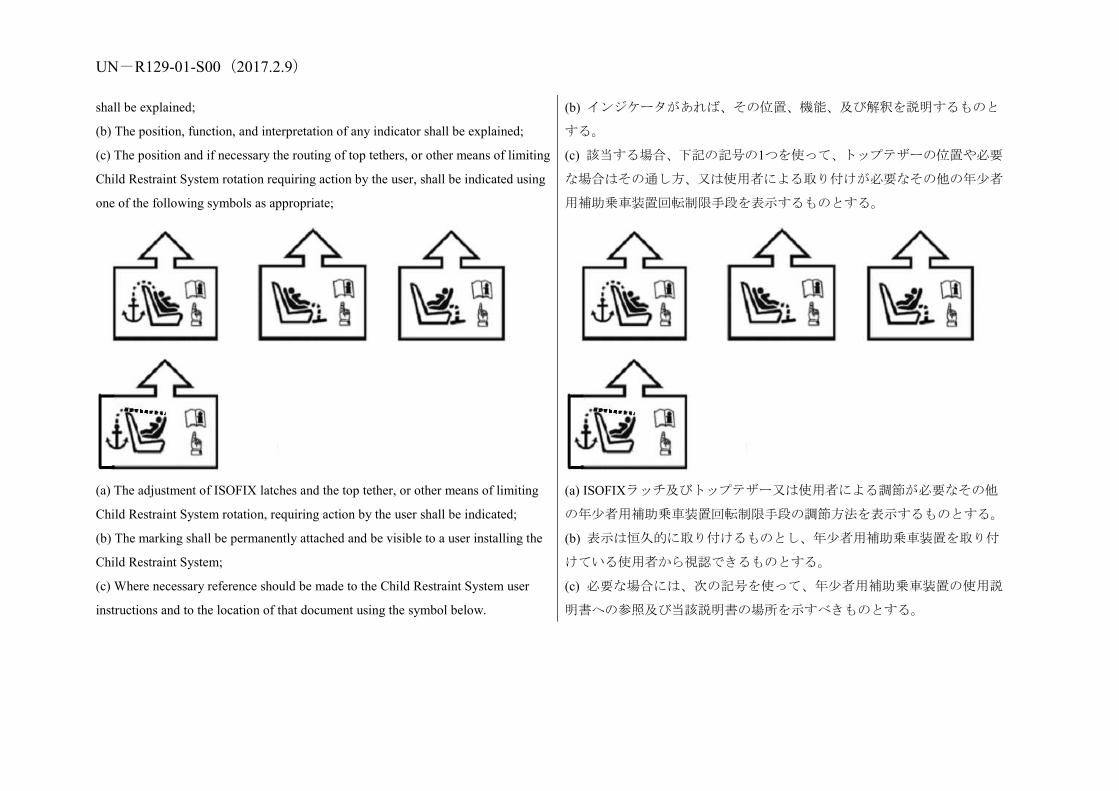
(b) The position, function, and interpretation of any indicator shall be explained;
(c) The position and if necessary the routing of top tethers, or other means of limiting
Child Restraint System rotation requiring action by the user, shall be indicated using
one of the following symbols as appropriate;
(a) The adjustment of ISOFIX latches and the top tether, or other means of limiting
Child Restraint System rotation, requiring action by the user shall be indicated;
(b) The marking shall be permanently attached and be visible to a user installing the
Child Restraint System;
(c) Where necessary reference should be made to the Child Restraint System user
instructions and to the location of that document using the symbol below.
(b) インジケータがあれば、その位置、機能、及び解釈を説明するものと
する。
(c) 該当する場合、下記の記号の1つを使って、トップテザーの位置や必要
な場合はその通し方、又は使用者による取り付けが必要なその他の年少者
用補助乗車装置回転制限手段を表示するものとする。
(a) ISOFIXラッチ及びトップテザー又は使用者による調節が必要なその他
の年少者用補助乗車装置回転制限手段の調節方法を表示するものとする。
(b) 表示は恒久的に取り付けるものとし、年少者用補助乗車装置を取り付
けている使用者から視認できるものとする。
(c) 必要な場合には、次の記号を使って、年少者用補助乗車装置の使用説
明書への参照及び当該説明書の場所を示すべきものとする。

UN-R129-01-S00(2017.2.9)
5. Approval 5. 認可
5.1.
Each sample submitted in conformity with paragraphs 3.2.4. and 3.2.5. above shall
meet the specifications set forth in paragraphs 6. to 7. of this Regulation in every
respect before approval can be granted.
5.1.
上記 3.2.4 項及び 3.2.5 項に従って提出される各サンプルは、すべての点に
おいて本規則の 6 項から 7 項に定める仕様に適合してはじめて認可を受け
ることができるものとする。
5.2.
An approval number shall be assigned to each type approved. Its first two digits (at
present 01 corresponding to the 01 series of amendments) shall indicate the series of
amendments incorporating the most recent major technical amendments made to the
Regulation at the time of issue of the approval. The same Contracting Party shall not
assign the same number to another type of Enhanced Child Restraint System covered
by this Regulation.
A type of Enhanced Child Restraint System approved according to this Regulation
shall not bear another approval mark according to Regulation No. 44 (Child Restraint
Systems).
5.2.
認可された各型式には認可番号を割り当てるものとする。その最初の2桁
(現在は「01」で、第1改訂版に相当する)は、認可が発行される時点で
本規則に加えられている最新の主要な技術的改訂を盛り込んだ改訂版を
示すものとする。同一締約国が、本規則の対象になる別の型式の年少者用
補助乗車装置に対して同一番号を割り当てないものとする。
本規則に従って認可される型式の年少者用補助乗車装置は、協定規則第 44
号(年少者用補助乗車装置)に従って、別の認可マークをつけないものと
する。
5.3.
Notice of approval or of extension or refusal of approval of a Child Restraint System
pursuant to this Regulation shall be communicated to the Parties to the Agreement
which apply this Regulation by means of a form conforming to the model in Annex 1
5.3.
本規則に準じた年少者用補助乗車装置の認可または認可の拡大もしくは
拒否は、本規則の附則 1 に示したモデルに適合する書式を用い、本規則を
適用する協定締約国に通知するものとする。改良型年少者用補助乗車装置

UN-R129-01-S00(2017.2.9) to this Regulation. If part of the enhanced child restraint system could be used as an
infant carrier module and installed as defined in Annex 22, approvals according to
this Regulation can only be granted if the infant carrier module complies with the
requirements of this annex."
の一部を乳児キャリアモジュールとして使用することができ、かつ附則 22
に定められたとおりに取り付けることができる場合には、本規則に基づく
認可は、当該乳児キャリアモジュールがこの附則の要件に適合している場
合に限り付与することができる。
5.4.
In addition to the marks prescribed in paragraph 4. above, the following particulars
shall be affixed in a suitable space to every Child Restraint System conforming to a
type approved under this Regulation:
5.4.
上記 4 項に定めたマークに加えて、本規則に基づいて認可された型式に適
合するすべての年少者用補助乗車装置には、以下の事項を適切な場所に貼
付するものとする。
5.4.1.
An international approval mark consisting of:
5.4.1.
以下で構成される国際認可マーク
5.4.1.1.
A circle surrounding the letter "E" followed by the distinguishing number of the
country which has granted approval;1 1 The distinguishing number of the Contracting Parties to the 1958 Agreement are
reproduced in Annex 3 to the Consolidated Resolution on the Construction of
Vehicles (R.E.3), document TRANS/WP.29/78/Rev.2/Amend.3.
5.4.1.1.
文字「E」の後に認可を付与した国の識別番号が続き、それらを円で囲ん
だもの。1 1 1958 年協定の締約国の識別番号は、車両構造統合決議(R.E.3)の附則 3、
文書 TRANS/WP.29/78/Rev.2/Amend.3 に再録されている。
5.4.1.2.
An approval number, the words "Regulation No." followed by the number of this
Regulation, a slash and the series of amendment ("Regulation
No. XXX/XX");
5.4.1.2.
認可番号、「規則 No.」という語に続けて本規則の番号、スラッシュおよび
改訂シリーズ(「規則 No. XXX/XXX」)
5.4.2.
The following additional symbols:
5.4.2.
以下の追加記号
5.4.2.1.
The words "i-Size universal ISOFIX", or "specific vehicle ISOFIX" depending on
the category of Enhanced Child Restraint System;
5.4.2.1.
改良型年少者用補助乗車装置のカテゴリーに応じて「アイサイズユニバー
サル ISOFIX」または「特定車両用 ISOFIX」という語
5.4.2.2. 5.4.2.2.

UN-R129-01-S00(2017.2.9) The size range for which the Enhanced Child Restraint System has been designed. In
case the ECRS is equipped with a module, the size range is not on the approval mark
but on the module mark. ECRS which can be converted into another configuration
for taller children shall accommodate an uninterrupted range of child statures.
改良型年少者用補助乗車装置の設計時に対象としたサイズ範囲。ECRS に
モジュールが装備されている場合、サイズ範囲は、認可マークではなくモ
ジュールマークに表示される。より身長の大きい幼児向けに構成を変える
ことができる ECRS は、連続する幼児身長範囲を対象とするものとする。
5.4.2.3.
The symbol "S" in the case of a "Special Needs Restraint".
5.4.2.3.
「特殊ニーズ拘束装置」の場合は、記号「S」。
5.4.3.
An international module mark as defined in Annex 2 of this Regulation consisting of:
5.4.3.
本規則の附則2に定義された、以下で構成される国際モジュールマーク:
5.4.3.1.
The words "R129" followed by a dash and the same approval number as the part of
the ECRS which includes the ISOFIX connectors;
5.4.3.1.
「R129」という語の後に、ダッシュならびにECRSのISOFIXコネクターを
含む部分と同じ認可番号を続ける。
5.4.3.2.
The words Module “name of the Module", depending on the name of the module of
Enhanced Child Restraint System;
5.4.3.2.
改良型年少者用補助乗車装置のモジュール名称に応じて、モジュール「モ
ジュール名称」という語。
5.4.3.3.
The size range including maximum weight for which the Module of the Enhanced
Child Restraint System has been designed;
5.4.3.3.
改良型年少者用補助乗車装置のモジュール設計時に対象とした最大体重
を含むサイズ範囲。
5.5.
Annex 2 to this Regulation gives an example of the arrangement of the approval
mark.
5.5.
本規則の附則 2 に認可マークの配置例を示す。
5.6.
The particulars referred to in paragraph 5.4. above shall be clearly legible and be
indelible, and may be affixed either by means of a label or by direct marking.
The label or marking shall be resistant to wear.
5.6.
上記 5.4 項で述べた事項は、明確に判読でき、かつ消えないものとし、ラ
ベル又は直接表示のどちらの方法でも貼付できる。ラベル又は表示は、摩
耗に耐えるものとする。
5.7.
The labels referred to in paragraph 5.6. above may be issued either by the Type
5.7.
上記 5.6 項で言及されているラベルは、認可を付与した行政官庁が発行し
UN-R129-01-S00(2017.2.9) Approval Authority which has granted the approval or, subject to that Type Approval
Authority's authorization, by the manufacturer.
てもよく、又は行政官庁が委任すればメーカーが発行してもよい。
6. General specifications 6. 一般仕様
6.1.
Positioning and securing on the vehicle
6.1.
車両上での位置決めと固定
6.1.1.
Enhanced Child Restraint Systems in the i-Size category are primarily designed for
use in i-Size seating positions, when the Enhanced Child Restraint Systems are fitted
in conformity with the vehicle manufacturer's instructions..
Enhanced Child Restraint Systems in the specific vehicle ISOFIX category are for
use in all ISOFIX positions and also in the luggage area, if the restraints are fitted in
conformity with the vehicle manufacturer's instructions.
6.1.1.
アイサイズ区分の改良型年少者用補助乗車装置は、改良型年少者用補助乗
車装置が車両メーカーの指示どおりに取り付けられる場合には、アイサイ
ズ着座位置で使用する。
「特定車両用 ISOFIX」区分の改良型年少者用補助乗車装置は、改良型年
少者用補助乗車装置が車両メーカーの指示どおりに取り付けられる場合
には、すべての ISOFIX 位置及び荷物区域で使用する。
6.1.2.
According to the category in which it belongs to, see Table 1, the integral Enhanced
Child Restraint System shall be secured to the vehicle structure or to the vehicle seat
structure:
6.1.2.
一体型改良型年少者用補助乗車装置を、その属する区分に従って(表 1 参
照)、車両構造又は車両座席構造に固定するものとする。
6.1.2.1.
For i-Size category, this shall be by means of two ISOFIX attachments with the
addition of an anti-rotation device for both forward and rearward-facing Child
Restraint System;
6.1.2.1.
アイサイズ区分については、2 つの ISOFIX 取り付け具を使うものとし、
それには前向きと後向きの年少者用補助乗車装置の両方に対する回転防
止装置が付いている。
6.1.2.2.
For "Specific Vehicle ISOFIX" category: this shall be by means of the ISOFIX
attachments designed by the manufacturer of the Child Restraint System, secured to
ISOFIX anchorage system as designed by the vehicle manufacturer.
Table 1: Possible configurations for type approval for Integral Enhanced Child
Restraint Systems.
6.1.2.2.
「特定車両用ISOFIX」区分については、年少者用補助乗車装置のメーカー
によって設計されたISOFIX取り付け具を使うものとし、それは、車両メー
カーによって設計されたISOFIX機構の取付装置に固定される。
表 1:一体型改良型型式認可用の可能な構成

UN-R129-01-S00(2017.2.9) Orientation Category
i-Size CRS Integral Specific Vehicle ISOFIX
CRS
INTEGRAL
Lateral facing (carry-cot) NA A
Rearward facing A A
Forward facing (integral) A A
With:
CRS: Child Restraint System
A: Applicable
NA: Non-Applicable
向き 区分
アイサイズCRS 一体型特定車両用ISOFIX CRS
一体型
横向き(キャリコッ
ト) NA A
後向き A A
前向き(一体型) A A
注:
CRS:年少者用補助乗車装置
A:適用可能
NA:非適用
6.1.2.3.
For children under the age of 15 months only lateral facing or rearward facing Child
Restraint System shall be used.
That means:
(a) A Child Restraint System designed for children up to 15 months of age shall be
rearward facing and accommodate at least a child with a stature of 83 cm;
(b) A forward facing Child Restraint System shall not be designed to accommodate a
stature below 71 cm;
(c) A convertible seat in its rearward facing configuration shall be able to
accommodate a child with a stature up to 83 cm. This shall not preclude a child
stature greater than 83 cm.
The use of rearward facing Child Restraint System may be applied to any age of
6.1.2.3.
月齢15カ月未満の幼児に対しては、横向き又は後向きの年少者用補助乗車
装置のみを使用するものとする。
すなわち、
(a) 月齢15カ月までの幼児用に設計される改良型年少者用補助乗車装置
は、後向きで、少なくとも身長83 cmの幼児を収容するものとする。
(b) 前向きの改良型年少者用補助乗車装置は、身長71 cm未満の幼児を収容
するようには設計しないものとする。
(c) 後向きの構成になっているコンバーチブル型の座席は、身長83 cmまで
の幼児を収容できるものとする。これは、身長が83 cmを超える幼児を除
外しないものとする。
後向きの改良型年少者用補助乗車装置の使用は、あらゆる月齢の幼児に適

UN-R129-01-S00(2017.2.9) child. 用してよい。
6.2.
Configuration of the Child Restraint System
6.2.
年少者用補助乗車装置の構成
6.2.1.
The configuration of the Child Restraint System shall be such that:
6.2.1.
年少者用補助乗車装置の構成は以下のとおりとする。
6.2.1.1.
The restraint of the child shall give the required protection in any position specified
for the Child Restraint System;
For "Special Needs Restraints" the primary means of restraint shall give the required
protection in any intended position of the Child Restraint System without the use of
the additional restraining devices which may be present;
6.2.1.1.
幼児の拘束は年少者用補助乗車装置用に指定されているいかなる位置に
おいても、要求される保護を提供するものとする。
「特殊ニーズ拘束装置」については、補助拘束装置があってもそれを使用
することなく、主要な拘束手段が、年少者用補助乗車装置の意図されてい
る位置での必要な保護を提供するものとする。
6.2.1.2.
The Enhanced Child Restraint System shall be such that the child may be easily and
readily restrained or removed. In the case of an Enhanced Child Restraint System in
which the child is restrained by means of a harness belt or a Y-shaped belt without a
retractor each shoulder restraint and lap strap shall be capable of movement relative
to each other during the procedure prescribed in paragraph 6.7.1.4. below; in these
cases the Enhanced Child Restraint System belt assembly may be designed with two
or more connecting parts.
For Special Needs Restraints it is recognized that the additional restraining devices
will restrict the speed by which a child can be restrained and removed. However, the
additional devices shall be designed to release quickly so far as possible;
6.2.1.2.
改良型年少者用補助乗車装置は、幼児を容易に迅速に拘束し、取り出すこ
とができるようにするものとする。幼児を巻取装置無しのハーネスベルト
又はY字形ベルトによって拘束する改良型年少者用補助乗車装置の場合、
各肩拘束装置及びラップ帯部は、下記6.7.1.4項に定める手順の実行中に、
互いに連動して動かせるようにする。このような場合、改良型年少者用補
助乗車装置のベルトアッセンブリは、2つ以上の接続部品があるように設
計してもよい。
「特殊ニーズ拘束装置」については、幼児を拘束し、取り出すことができ
る速度が補助拘束装置によって制限されると認識されている。ただし、補
助装置は、可能な限り迅速に解除されるように設計するものとする。
6.2.1.3.
If it is possible to change the inclination of the Child Restraint System, this change in
inclination shall not require manual readjustment of any other part of the Child
Restraint System. A deliberate hand-action shall be necessary in order to change the
6.2.1.3.
年少者用補助乗車装置の傾きを変更することが可能な場合、この傾きの変
更のために年少者用補助乗車装置の他の部分を手で調節し直す必要が生
じないものとする。年少者用補助乗車装置の傾きを変更するには、意図的
UN-R129-01-S00(2017.2.9) inclination of the Child Restraint System; な手動操作を必要とするものとする。
6.2.1.4.
To prevent submarining, either by impact or through restlessness, a crotch strap shall
be required on all integral forward-facing restraints incorporating an integral harness
belt system.
6.2.1.4.
衝撃または絶え間ない動きによって幼児がずり落ちることを防ぐために、
一体型ハーネスベルトシステムを組み込んだすべての一体型前向き拘束
装置は、クロッチストラップを必要とするものとする。
6.2.1.5.
All restraint devices utilizing a lap strap shall positively guide the lap strap to ensure
that the loads transmitted by the lap strap are transmitted through the pelvis. The
assembly shall not subject weak parts of the child’s body (abdomen, crotch, etc.) to
excessive stresses.
Moreover, the design shall be such that compression loads shall not be imposed on
the crown of the child’s head in the event of a collision;
6.2.1.5.
「ラップストラップ」を用いるすべての拘束装置は、「ラップストラップ」
によって伝達される負荷が骨盤を通して伝達されるように「ラップストラ
ップ」を確実に誘導しなければならない。年少者用補助乗車アッセンブリ
は、幼児の身体の弱い部分(腹部、股間など)を過度に圧迫しないものと
する。衝突の際に圧力が幼児の頭頂部にかからないように設計するものと
する。
6.2.1.6.
All straps of the restraint shall be so placed that they cannot cause discomfort to the
wearer in normal use or assume a dangerous configuration. Y-shaped belts are not
permitted on forward facing Enhanced Child Restraint Systems and may only be
used in dedicated rearward facing and or lateral facing Enhanced Child Restraint
Systems (carrycots). The distance between the shoulder-straps in the vicinity of the
neck should be at least the width of the neck of the appropriate dummy.
6.2.1.6.
拘束装置のストラップはすべて、通常使用するとき装着者に不快感を与え
たり、危険な形態にならないように配置するものとする。Y字形ベルトは、
前向きの改良型年少者用補助乗車装置での使用は許可されず、後向きおよ
び/または横向き専用の改良型年少者用補助乗車装置(キャリコット)に
おいてのみ使用してよい。ショルダーストラップ間の距離は、首の近くで
は少なくとも該当するダミーの首の幅とする。
6.2.1.7.
With the crotch strap attached and in its longest position if adjustable, it shall not be
possible to adjust the lap strap to lie above the pelvis of both the smallest and largest
dummy within the size range covered by the approval. For all forward-facing
restraints, it shall not be possible to adjust the lap strap to lie above the pelvis of both
the smallest and largest dummy within the size range covered by the approval.
6.2.1.7.
クロッチストラップを装着し、調節可能な場合は、最も伸ばした位置にし
たときに、ラップストラップが認可対象サイズ範囲内の最小のダミーと最
大のダミーの両方の骨盤の上にくるようには調節できないものとする。す
べての前向き拘束装置については、ラップストラップが認可対象の質量グ
ループ内で最小のダミーと最大のダミーの両方の骨盤の上にくるように
は調節できないものとする。

UN-R129-01-S00(2017.2.9) 6.2.1.8.
During the dynamic test, as prescribed in paragraph 8.1.3., the lap belt shall not pass
fully beyond the pelvic structure of the dummy during the period prior to maximum
horizontal head excursion. An assessment shall be carried out using high speed video
imaging.
6.2.1.8.
8.1.3項に規定した動的テスト中、水平方向の最大頭部変位の前にラップベ
ルトがダミーの骨盤構造を完全に超えて横断しないものとする。高速ビデ
オ画像を用いて評価を実施するものとする。
6.2.1.9.
At least the worst case configuration of the dynamic test for the Enhanced Child
Restraint System shall be performed after conditioning according to paragraph 7.2.6.
6.2.1.9.
7.2.6項に基づくコンディショニングの後、改良型幼児拘束装置の動的テス
トを少なくとも最悪ケースの構成で実施するものとする。
6.2.2.
The Child Restraint System shall be designed and installed so as to:
6.2.2.
年少者用補助乗車装置は、以下のように設計し、装備するものとする。
6.2.2.1.
Not exhibit sharp edges or protrusions liable to cause damage to vehicle-seat covers
or to occupant's clothing;
6.2.2.1.
車両座席カバーや乗員の洋服に損傷をもたらす恐れのある鋭利な先端部
又は突起を露出しないこと。
6.2.2.2.
To ensure that its rigid parts do not, at any point, where they are in contact with
straps, exhibit sharp edges capable of abrading the straps.
6.2.2.2.
装置の剛性部品が、帯部と接触する部分のいずれの点においても、帯部を
摩擦する恐れのある鋭利な先端部を露出しないようにすること。
6.2.3.
It shall not be possible to remove or detach without the use of specific tools, any
components not designed to be removable or detachable. Any components that are
designed to be removable for maintenance or adjustment purpose shall be so
designed as to avoid any risk of incorrect assembly and use, as the assembly and
disassembly processes shall be explained in detail in the restraint user guides. Any
harness belt shall be capable of its full range of adjustment without disassembly.
6.2.3.
取り外し又は着脱可能に設計されていない構成部品は、特殊な工具を使用
することなく取り外し又は着脱できないようにするものとする。保守や調
節目的で取り外しできるように設計されている構成部品は、誤った組立て
や使用がなされる危険を回避するように設計するものとし、組立てと分解
プロセスは詳しく拘束装置のユーザーガイドで説明するものとする。ハー
ネスベルトは分解しなくても全範囲の調節を可能にするものとする。
6.2.4.
"Special Needs Restraints" may have additional restraining devices; these shall be
designed to avoid any risk of incorrect assembly, and shall be designed so that their
6.2.4.
「特殊ニーズ拘束装置」には、補助拘束装置があってもよい。これは、誤
って組み立てられる危険を回避するように設計するものとし、緊急時に救
UN-R129-01-S00(2017.2.9) means of release and mode of operation is immediately obvious to any rescuer in an
emergency.
助者に解除手段や操作モードが即座に明らかになるように設計するもの
とする。
6.2.5.
An Enhanced Child Restraint System may be designed for use in any size range
specified by the manufacturer provided that it satisfies the requirements laid down in
this Regulation.
6.2.5.
改良型年少者用補助乗車装置は、本規則に規定されている要件を満たす場
合、メーカーによって指定されるいずれのサイズの範囲で使用されるよう
に設計できる。
6.2.6.
Child Restraint Systems incorporating inflatable elements shall be so designed that
the conditions of use (pressure, temperature, humidity) have no influence on their
ability to comply with the requirements of this Regulation.
6.2.6.
膨らませることができる構成要素を組み込んだ年少者用補助乗車装置は、
その使用条件(圧力、温度、湿度)が本規則の要件に対する当該装置の適
合能力に何ら影響を及ぼさないように設計するものとする。
6.3.
Child Restraint System specifications
6.3.
年少者用補助乗車装置の仕様
6.3.1.
Material
6.3.1.
材料
6.3.1.1.
The Enhanced Child Restraint System manufacturer shall declare in writing that the
toxicity of materials used in the manufacture of restraint systems and accessible to
the restrained child is in conformity with the relevant parts of EN 71-3 in its last
edited version. Tests confirming the validity of the declaration may be carried out at
the discretion of the test authority.
6.3.1.1.
改良型年少者用補助乗車装置メーカーは、拘束装置の製造時に使用され、
かつ拘束された幼児の手が届く材料の毒性が、最新版のEN 71-2の関連部分
に適合することを書面で宣言するものとする。宣言の正当性を確認するテ
ストをテスト当局の裁量により実施することができる。
6.3.1.2.
The Enhanced Child Restraint System manufacturer shall declare in writing that the
flammability of materials used to manufacture the Enhanced Child Restraint System
is in conformity with the relevant paragraphs of EN 71-2 in its last edited version.
Tests confirming the validity of the declaration may be carried out at the discretion
of the test authority.
6.3.1.2.
改良型年少者用補助乗車装置のメーカーは、拘束装置の製造時に使用した
材料の可燃性が最新版のEN 71-2の関連項目に適合することを、書面で宣言
するものとする。宣言の正当性を確認するテストをテスト当局の裁量によ
り実施することができる。

UN-R129-01-S00(2017.2.9) 6.3.2.
General characteristics
6.3.2.
一般特性
6.3.2.1.
Internal geometric characteristics
The Technical Service conducting the approval tests shall verify that the internal
dimensions of the Enhanced Child Restraint System conform to the requirements of
Annex 18. For any size within the size range declared by the manufacturer the
dimensions for minimum shoulder breadth, minimum hip breadth and minimum
sitting height shall be fulfilled as well as the dimensions for minimum and maximum
shoulder height.
6.3.2.1.
内部の幾何学的特徴
認可試験を実施する技術機関は、改良型年少者用補助乗車装置の内部寸法
が附則18の要件に適合することを確認するものとする。メーカーによって
宣言されたサイズ範囲内のどのサイズについても、肩幅、ヒップ幅、座高
の最小寸法、ならびに肩の高さの最小及び最大寸法を満たすものとする。
6.3.2.2.
External dimensions
The Universal Integral Class Enhanced Child Restraint Systems shall be adjusted to
the largest size of its declared stature range (height, depth and width dimensions as
defined in Annex 18). The Enhanced Child Restraint System may be adjusted to
other inclined positions (less or more reclined) that are outside the Vehicle Seat
Fixture’s height; in this case, the child restraint manufacturer’s user manual shall
clearly indicate that when used in one of these configurations, the Enhanced Child
Restraint System may not fit in all vehicles approved for a Universal fixture."
6.3.2.2.
外部寸法
汎用一体型クラス改良型年少者用補助乗車装置は、公表された身長範囲
(附則18に規定された高さ、奥行きおよび幅の寸法)の最も大きいサイズ
に調節するものとする。車両シート固定具の高さ範囲外にあるその他の傾
斜位置(ある程度リクライニングさせた位置)に改良型年少者用補助乗車
装置を調節してもよい。この場合、年少者用補助乗車装置メーカーのユー
ザーマニュアルに、これらの構成のいずれかで使用する場合には当該改良
型年少者用補助乗車装置は汎用固定具に関して認可されたすべての車両
に取り付けられるとは限らないことを明確に示すものとする。
6.3.2.2.1.
Integral Class Enhanced Child Restraint Systems
The maximum dimensions for width, height and depth of the Enhanced Child
Restraint System and the locations of the ISOFIX anchorages system with which its
attachments shall engage, shall be defined by the ISOFIX Vehicle Seat Fixture as
6.3.2.2.1.
一体型クラス改良型年少者用補助乗車装置
改良型年少者用補助乗車装置の幅、高さ、奥行きの最大寸法と、年少者用
補助乗車装置の取り付け具がかみ合うものとするISOFIX取付装置システ
ムの位置は、本規則の2.17.1.項に定められているISOFIX車両シート固定具

UN-R129-01-S00(2017.2.9) defined in paragraph 2.17.1. of this Regulation.
(a) i-Size Forward facing Enhanced Child Restraint Systems shall fit within the
ISO/F2x size envelope for a reduced-height forward-facing toddler CRS ISOFIX
SIZE CLASS B1;
(b) i-Size Rearward facing Enhanced Child Restraint Systems shall fit
within the ISO/R2 size envelope for a reduced-size rearward-facing
toddler CRS ISOFIX SIZE CLASS D;
(c) Specific vehicle ISOFIX Enhanced Child Restraint Systems shall
fit in vehicle(s) specified in a list or
(d) Shall fit at least in one of ISO (R1, R2, R3, F2, F2X, F3, L1, L2) size envelope as
described in Annex 17 Appendix 2 of Regulation No. 16.
によって規定されるものとする。
(a) アイサイズ前向き年少者用補助乗車装置は、低型前向き幼児用CRS(高
さ650 mm)ISOFIX SIZE CLASS B1用のISO/F2xサイズのエンベロープ内に
収まるものとする。
(b) アイサイズ後向き年少者用補助乗車装置は、小型後向き幼児用CRS
ISOFIX SIZE CLASS D用のISO/R2サイズのエンベロープ内に収まるもの
とする。
(c) 「特定車両用ISOFIX」年少者用補助乗車装置は、ISOサイズのエンベ
ロープ内に収まればよい。
(d) 少なくとも、規則No. 16、附則17の付録2に記載されたISO(R1、R2、
R3、F2、F2X、F3、L1、L2)サイズのエンベロープのうちのいずれかに収
まるものとする。
6.3.2.3.
Mass
The mass of an integral ISOFIX Child Restraint System (i-Size Child Restraint
System included) combined with the mass of the largest child intended to use the
Child Restraint System shall not exceed 33 kg. This mass limit is also applicable for
"Specific vehicle ISOFIX" Child Restraint Systems.
6.3.2.3.
質量
年少者用補助乗車装置の使用対象の子供のうち、最大の子供の質量と合わ
せた、一体型ISOFIX年少者用補助乗車装置(アイサイズ年少者用補助乗車
装置を含む)の質量は、33 kgを超えないものとする。この質量限界は、「特
定車両用ISOFIX」年少者用補助乗車装置にも適用可能である。
6.3.3.
ISOFIX attachments
6.3.3.
ISOFIX 取り付け具
6.3.3.1.
Type
ISOFIX attachments may be according to examples shown in Figure 0(a), or other
appropriate designs that are part of a rigid mechanism having provision for
adjustment, the nature of which is determined by the ISOFIX Child Restraint System
manufacturer.
6.3.3.1.
型式
ISOFIX取り付け具は、図0(a)に示す例に従うものか、又は調節機能のある
剛性メカニズムの一部であるその他の適切な設計でもよく、その性質は
ISOFIX年少者用補助乗車装置メーカーが決定する。

UN-R129-01-S00(2017.2.9) Figure 0(a)
Key
1 ISOFIX Child Restraint System attachment - example 1
2 ISOFIX Child Restraint System attachment - example 2
図0(a)
凡例
1 ISOFIX年少者用補助乗車装置取り付け具—例1
2 ISOFIX 年少者用補助乗車装置取り付け具—例 2
6.3.3.2.
Dimensions
Dimensions for the portion of the ISOFIX Child Restraint System attachment that
engages the ISOFIX anchorage system shall not exceed the maximum dimensions
given by the envelope in Figure 0(b).
Figure 0(b)
6.3.3.2.
寸法
ISOFIX年少者用補助乗車装置取り付け具のISOFIX機構の取付装置とかみ
合う部分の寸法は、図0(b)のエンベロープが示す最大寸法を超えないもの
とする。
図 0(b)

UN-R129-01-S00(2017.2.9) 6.3.3.3.
Partial latching indication
The ISOFIX Child Restraint System shall incorporate means by which there is a
clear indication that both of the ISOFIX attachments are completely latched with the
corresponding ISOFIX lower anchorages. The indication means may be audible,
tactile or visual or a combination of two or more. In case of visual indication it shall
be detectable under all normal lighting conditions.
6.3.3.3.
部分ラッチ表示
ISOFIX年少者用補助乗車装置には、ISOFIX取り付け具の両方が、対応す
るISOFIX下部取付装置との間で、完全にラッチがかかることを明確に表示
する手段を組み込むものとする。この表示手段は、聴覚、触覚又は視覚的
方法のいずれでもよく、又は2つ以上の組み合わせでもよい。視覚的表示
の場合には、あらゆる通常の照明条件下で検知可能とする。
6.3.4.
ISOFIX Child Restraint System top tether strap specifications
6.3.4.
ISOFIX 年少者用補助乗車装置トップテザー帯部の仕様
6.3.4.1.
Top tether connector
The top tether connector shall be ISOFIX top tether hook as shown in Figure 0(c), or
similar devices that fit within the envelope given by Figure 0(c).
6.3.4.1.
トップテザーコネクター
トップテザーコネクターは、図 0(c)に示す ISOFIX トップテザーフック、
又は図 0(c)に示すエンベロープ内に収まる類似の装置であるものとする。
6.3.4.2.
ISOFIX top tether strap features
The ISOFIX top tether strap shall be supported by webbing (or its equivalent),
having a provision for adjustment and release of tension.
6.3.4.2.
ISOFIXトップテザー帯部の特徴
ISOFIX トップテザー帯部は、調節及び張力解除の機能を備えたウェビン
グ(又はそれと同等のもの)によって支えるものとする。
6.3.4.2.1.
ISOFIX Top tether strap length
ISOFIX Child Restraint System top tether strap length shall be at least 2,000 mm.
6.3.4.2.1.
ISOFIXトップテザー帯部の長さ
ISOFIX 年少者用補助乗車装置トップテザー帯部の長さは少なくとも 2,000
mm とする。
6.3.4.2.2.
No-slack indicator
The ISOFIX top tether strap or the ISOFIX Child Restraint System shall be equipped
with a device that will indicate that all slack has been removed from the strap. The
device may be part of an adjustment and tension relieving device.
6.3.4.2.2.
緩みなしインジケータ
ISOFIXトップテザー帯部又はISOFIX年少者用補助乗車装置には、帯部か
らすべての緩みが取り除かれていることを示す装置を備えるものとする。
この装置は調節及び張力解除装置の一部でもよい。
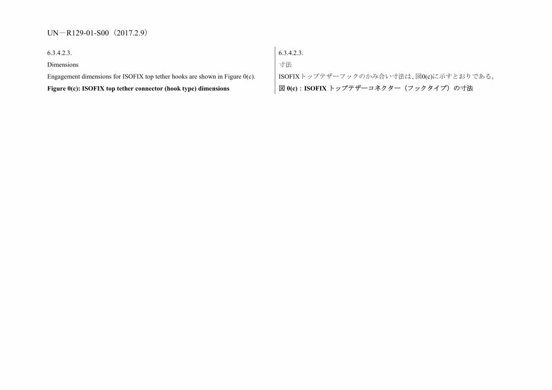
UN-R129-01-S00(2017.2.9) 6.3.4.2.3.
Dimensions
Engagement dimensions for ISOFIX top tether hooks are shown in Figure 0(c).
Figure 0(c): ISOFIX top tether connector (hook type) dimensions
6.3.4.2.3.
寸法
ISOFIXトップテザーフックのかみ合い寸法は、図0(c)に示すとおりである。
図 0(c):ISOFIX トップテザーコネクター(フックタイプ)の寸法

UN-R129-01-S00(2017.2.9)
6.3.5.
i-Size Child Restraint System support-leg and support-leg foot requirements
6.3.5.
アイサイズ年少者用補助乗車装置脚部保護装置と脚部保護装置フットの
UN-R129-01-S00(2017.2.9)
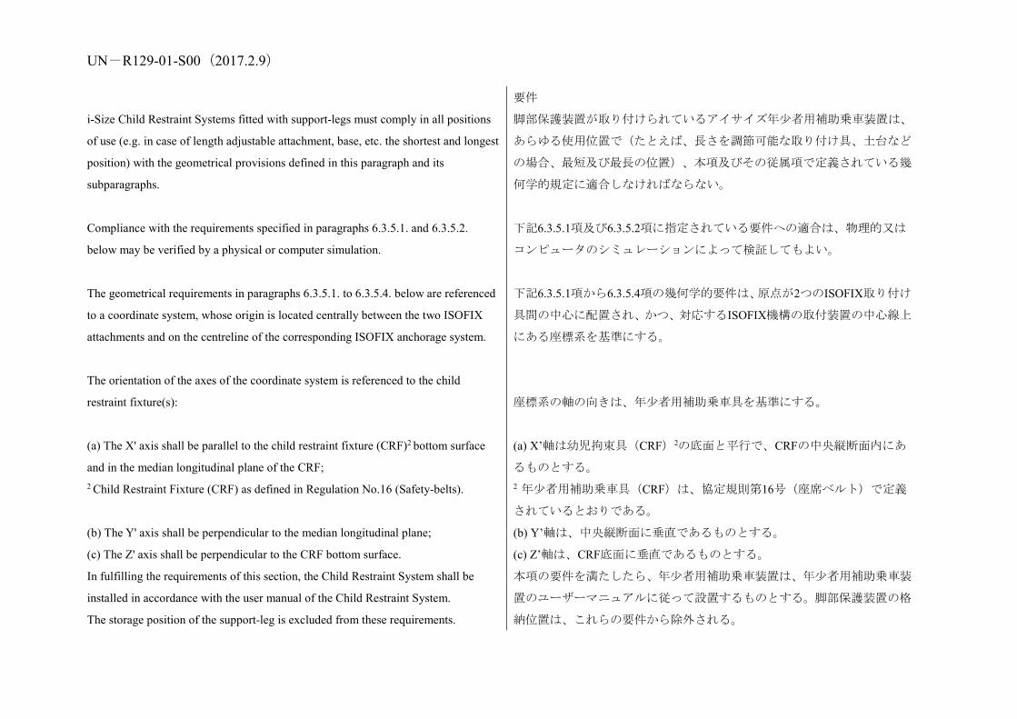
i-Size Child Restraint Systems fitted with support-legs must comply in all positions
of use (e.g. in case of length adjustable attachment, base, etc. the shortest and longest
position) with the geometrical provisions defined in this paragraph and its
subparagraphs.
Compliance with the requirements specified in paragraphs 6.3.5.1. and 6.3.5.2.
below may be verified by a physical or computer simulation.
The geometrical requirements in paragraphs 6.3.5.1. to 6.3.5.4. below are referenced
to a coordinate system, whose origin is located centrally between the two ISOFIX
attachments and on the centreline of the corresponding ISOFIX anchorage system.
The orientation of the axes of the coordinate system is referenced to the child
restraint fixture(s):
(a) The X' axis shall be parallel to the child restraint fixture (CRF)2 bottom surface
and in the median longitudinal plane of the CRF; 2 Child Restraint Fixture (CRF) as defined in Regulation No.16 (Safety-belts).
(b) The Y' axis shall be perpendicular to the median longitudinal plane;
(c) The Z' axis shall be perpendicular to the CRF bottom surface.
In fulfilling the requirements of this section, the Child Restraint System shall be
installed in accordance with the user manual of the Child Restraint System.
The storage position of the support-leg is excluded from these requirements.
要件
脚部保護装置が取り付けられているアイサイズ年少者用補助乗車装置は、
あらゆる使用位置で(たとえば、長さを調節可能な取り付け具、土台など
の場合、最短及び最長の位置)、本項及びその従属項で定義されている幾
何学的規定に適合しなければならない。
下記6.3.5.1項及び6.3.5.2項に指定されている要件への適合は、物理的又は
コンピュータのシミュレーションによって検証してもよい。
下記6.3.5.1項から6.3.5.4項の幾何学的要件は、原点が2つのISOFIX取り付け
具間の中心に配置され、かつ、対応するISOFIX機構の取付装置の中心線上
にある座標系を基準にする。
座標系の軸の向きは、年少者用補助乗車具を基準にする。
(a) X’軸は幼児拘束具(CRF)2の底面と平行で、CRFの中央縦断面内にあ
るものとする。 2 年少者用補助乗車具(CRF)は、協定規則第16号(座席ベルト)で定義
されているとおりである。
(b) Y’軸は、中央縦断面に垂直であるものとする。
(c) Z’軸は、CRF底面に垂直であるものとする。
本項の要件を満たしたら、年少者用補助乗車装置は、年少者用補助乗車装
置のユーザーマニュアルに従って設置するものとする。脚部保護装置の格
納位置は、これらの要件から除外される。

UN-R129-01-S00(2017.2.9)
6.3.5.1.
Support-leg and support-leg foot geometrical requirements
The support leg, including its attachment to the child restraint systems and the
support-leg foot shall lie completely within the support leg dimension assessment
volume (see also Figures 1 and 2 of Annex 19 of this Regulation), which is defined
as follows:
(a) In width by two planes parallel to the X'-Z' plane separated by 200 mm, and
centered around the origin; and
(b) In length by two planes parallel to the Z'-Y' plane and positioned at distances of
585 mm and 695 mm forward of the origin along the X' axis; and
(c) In height by a plane parallel to the X'-Y' plane, positioned at a distance of 70 mm
above the origin and measured perpendicular to the X'-Y' plane. Rigid,
non-adjustable parts of the support leg shall not extend beyond a plane parallel to the
X'-Y' plane, positioned at a distance of 285 mm below the origin and perpendicular
to the X'-Y' plane.
6.3.5.1.
脚部保護装置と脚部保護装置フットの幾何学的要件
脚部保護装置は、年少者用補助乗車装置への取り付け具と脚部保護装置フ
ットを含めて、脚部保護装置寸法評価体積内に完全に収まるものとする
(本規則の附則19の図1と図2も参照)。それは以下のように定義されてい
る。
(a) X’-Z’平面に平行で200 mmの間隔があり、原点を中心とした2つの平面
によって規定する幅、かつ
(b) Z’-Y’平面に平行で、原点から X’軸に沿って 585 mm と 695 mm 前方に
位置する 2 つの平面によって規定する奥行、かつ
(c) X’-Y’平面に平行で、X’-Y’平面に垂直に測定したときに原点から70
mm上方に位置する面で規定する高さ。脚部保護装置の調節不能な剛性部
分は、X’-Y’平面に平行で、X’-Y’平面に垂直に測定したときに原点から285
mm下方に位置する平面を越えないものとする。

UN-R129-01-S00(2017.2.9) 6.3.5.2.
Support-leg foot adjustability requirements
The support-leg shall be adjustable in order to ensure that the support-leg foot can be
positioned throughout the height range of the support-leg foot assessment volume as
specified below (see also Figures 3 and 4 of Annex 19 to this Regulation). Where
incremental adjustment is provided, the step between two locked positions shall not
exceed 20 mm.
The support leg foot assessment volume is defined as follows:
(a) In width by two planes parallel to the X'-Z' plane, separated by 200 mm, and
centered around the origin; and
(b) In length by two planes parallel to the Z'-Y' plane and positioned at distances of
585 mm and 695 mm forward of the origin along the X' axis; and
(c) In height by two planes parallel to the X'-Y' plane positioned at distances of 285
mm and 540 mm below the origin along the X' axis.
It shall be permissible for the support-leg to be adjustable beyond the height limits in
the Z' direction (as indicated by key 6 in figure 3 of Annex 19), providing that no
parts extend beyond the limiting planes in the X' and Y' directions.
6.3.5.2.
脚部保護装置フットの調節可能性の要件
脚部保護装置は、脚部保護装置フットが下記に指定されている脚部保護装
置フット評価体積の高さ範囲全体にわたって配置できるようにするため、
調節可能とする(本規則の附則19の図3及び図4も参照)。増分調節を提供
する場合、2つのロックされた位置の間の段間距離は、20 mmを超えないも
のとする。
脚部保護装置フット評価体積は以下のように定義される。
(a) X’-Z’平面に平行で200 mmの間隔があり、原点を中心とした2つの平面
によって規定する幅、かつ
(b) Z’-Y’平面に平行で、原点からX’軸に沿って585 mmと695 mm前方に位置
する2つの平面によって規定する奥行、かつ
(c) X’-Y’平面に平行で、原点からX’軸に沿って285 mmと540 mm下方に位
置する2つの平面によって規定する高さ。
サポートレッグは、いかなる部分も X’および Y’方向に限界面を越えてい
ない場合は、Z’方向に高さ制限値を超えて調節可能にすることは許容され
るものとする(附則 19 の図 3 の凡例 6 で示すとおり)。
6.3.5.3.
Support-leg foot dimensions
The dimensions of the support-leg foot shall meet the following requirements:
(a) Minimum support-leg contact surface shall be 2,500 mm2, measured as a
projected surface 10 mm above the lower edge of the support-leg foot (see Figure
0(d));
(b) Minimum outside dimensions shall be 30 mm in the X' and Y' directions, with
maximum dimensions being limited by the support-leg foot assessment volume;
6.3.5.3.
脚部保護装置フットの寸法
脚部保護装置フットの寸法は、以下の要件を満たすものとする。
(a) 最小脚部保護装置接触面は、脚部保護装置フットの下端から10 mm上の
推定表面として計算され、2,500 mm2となるものとする(図0(d)を参照)。
(b) 最小外形寸法はX’およびY’方向に30 mmとなるものとし、最大寸法は
脚部保護装置フット評価体積によって制限されている。

UN-R129-01-S00(2017.2.9) (c) Minimum radius of the edges of the support-leg foot shall be 3.2 mm.
Figure 0(d)
(c) 脚部保護装置フットの端の最小半径は3.2 mmとする。
図 0(d)
6.3.5.4.
Support-leg foot jig
A jig shall be used to check that the support-leg foot meets the requirements defined
in paragraph 6.3.5.2. above (see Figure 0(e)). As an alternative a computer
simulation shall also be considered satisfactory.
The jig is defined as the ISOFIX CRF corresponding to the size class of the
Enhanced Child Restraint System. The jig is expanded with two 6 mm diameter
ISOFIX low anchorages. The striped box positioned in front of the jig is positioned
and sized according paragraph 6.3.5.2. above. The ECRS shall have its attachments
latched when conducting the assessment.
Figure 0(e)
6.3.5.4.
脚部保護装置フット装具
装具は、脚部保護装置が上記6.3.5.2項で定義されている要件を満たしてい
るかチェックするのに使用するものとする(図0(e)参照)。代替策として、
コンピュータシミュレーションでも、要件を満たすとみなすものとする。
装具は、改良型年少者用補助乗車装置のサイズクラスに対応するISOFIX
CRFとして定義される。装具は、2個の6 mm径のISOFIX下部取付装置で拡
張される。装具の前に配置されている縞模様のボックスは、上記6.3.5.2項
に従って配置され、サイズ調節される。CRSには、評価を実施するときに
ラッチがかかる取り付け具があるものとする。
図 0(e)
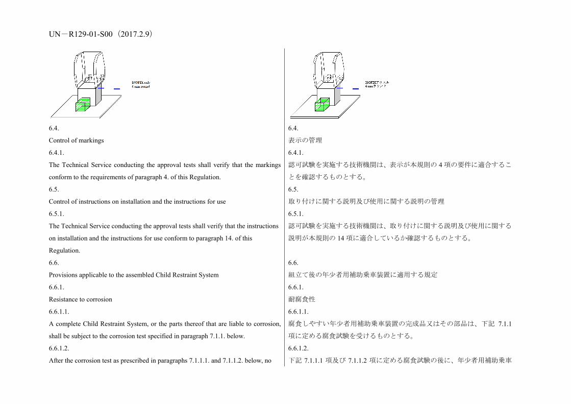
UN-R129-01-S00(2017.2.9)
6.4.
Control of markings
6.4.
表示の管理
6.4.1.
The Technical Service conducting the approval tests shall verify that the markings
conform to the requirements of paragraph 4. of this Regulation.
6.4.1.
認可試験を実施する技術機関は、表示が本規則の 4 項の要件に適合するこ
とを確認するものとする。
6.5.
Control of instructions on installation and the instructions for use
6.5.
取り付けに関する説明及び使用に関する説明の管理
6.5.1.
The Technical Service conducting the approval tests shall verify that the instructions
on installation and the instructions for use conform to paragraph 14. of this
Regulation.
6.5.1.
認可試験を実施する技術機関は、取り付けに関する説明及び使用に関する
説明が本規則の 14 項に適合しているか確認するものとする。
6.6.
Provisions applicable to the assembled Child Restraint System
6.6.
組立て後の年少者用補助乗車装置に適用する規定
6.6.1.
Resistance to corrosion
6.6.1.
耐腐食性
6.6.1.1.
A complete Child Restraint System, or the parts thereof that are liable to corrosion,
shall be subject to the corrosion test specified in paragraph 7.1.1. below.
6.6.1.1.
腐食しやすい年少者用補助乗車装置の完成品又はその部品は、下記 7.1.1
項に定める腐食試験を受けるものとする。
6.6.1.2.
After the corrosion test as prescribed in paragraphs 7.1.1.1. and 7.1.1.2. below, no
6.6.1.2.
下記 7.1.1.1 項及び 7.1.1.2 項に定める腐食試験の後に、年少者用補助乗車

UN-R129-01-S00(2017.2.9) signs of deterioration likely to impair the proper functioning of the Child
Restraint System, and no significant corrosion, shall be visible to the unaided eye of
a qualified observer.
装置の適正な機能を損なう恐れがある劣化の兆候や、顕著な腐食が、公認
検査員の肉眼で視認されないものとする。
6.6.2.
Energy absorption
6.6.2.
エネルギー吸収
6.6.2.1.
For all devices with backrests, the areas defined in Annex 14 to this Regulation,
when tested according to Annex 13, shall give a peak acceleration of less than 60g.
This requirement applies also to areas of impact shields which are in the head strike
area.
6.6.2.1.
すべての背もたれ付き装置について、本規則の附則14に定める区域は、附
則13に従って測定したときに、60 g未満のピーク加速度を示すものとする。
本要件は、頭部衝突区域内のインパクトシールドの区域にも適用する。
6.6.2.2.
In the case of child restraint systems with permanent mechanically attached
adjustable head support devices, in which the height of either the adult safety belt or
of the child harness is directly controlled by the adjustable head support, it is not
necessary to demand energy absorption in areas as defined in Annex 18, which are
not contactable by the manikin’s head, i.e. behind the head support.
6.6.2.2.
調節可能なヘッドサポート装置が恒久的かつ機械的に取り付けられてお
り、成人用安全ベルトまたは幼児用ハーネスのいずれかの高さが当該調節
可能ヘッドサポートにより直接制御される年少者用補助乗車装置の場合、
附則18に定める区域(マネキンの頭部が接触しない区域、すなわちヘッド
サポートの後ろ)内にエネルギー吸収材を要求する必要はない。
6.6.3.
Overturning
6.6.3.
転覆
6.6.3.1.
The child restraint system shall be tested as prescribed in paragraph 7.1.2.; at no
point during the whole test shall the manikin be fully ejected from the device. In
addition when the test seat is in the upside down position, the dummy’s head shall
not move more than 300 mm from its original position in a vertical direction relative
to the test seat.
6.6.3.1.
改良型年少者用補助乗車装置は、7.1.2 項に定めるようにテストするものと
する。テスト全体のいかなる時点においても、マネキンが装置から完全に
飛び出さないものとする。さらに、テスト用シートを上下逆さにしたとき、
ダミー頭部がテスト用シートに対して垂直方向に元の位置から 300 mm を
超えて動かないものとする。
6.6.4.
Dynamic test
6.6.4.
動的試験

UN-R129-01-S00(2017.2.9) 6.6.4.1.
General: The dynamic test shall be performed on Enhanced Child Restraint Systems
which have not previously been under load and the Enhanced Child Restraint System
shall be subjected to dynamic tests, in accordance with Table 4, in conformity with
paragraph 7.1.3. below:
Table 4: Application of different criteria depending of test set up
Frontal impact Rear impact Lateral impact
Test on trolley+ standard seat Test in car body
Test on trolley+ standard
seat
Test in car body
Test on trolley+ standard seat
Forward facing
Rearward and lateral facing
Forward facing
Rearward and lateral facing
Rearward and lateral facing
Rearward and lateral facing
Forward facing
Rearward and lateral facing
Note 1: Standard seat means a test seat or test bench as defined in Annex 6.
Note 2: For lateral facing Enhanced Child Restraint Systems in lateral impact, if two
positions are possible, then the dummy’s head shall be situated near the side door.
6.6.4.1.
一般要件:動的試験は、以前に不可を受けた事がない改良型年少者用補助
乗車装置で実施するものとし、改良型年少者用補助乗車装置は、表4に従
って、下記7.1.3項に基づいて、動的試験を受けるものとする。
表 4:試験のセットアップに応じた異なる基準の適用
前面衝突 後面衝突 側面衝突
台車上の試験+ 標準座席 車体内の試験
台車上の試験+
標準座席 車体内の
試験 台車上の試験+
標準座席
前向き
後向き及び横向き
前向き
後向き及び横向き
後向き及び横向き
後向き及び横向き 前向き 後向き及
び横向き
注1:標準座席とは、附則6に定義された試験用座席又は試験台をいう。
注 2:側面衝突での横向きの改良型年少者用補助乗車装置については、2
つの位置が可能な場合、ダミーの頭部はサイドドア近くに配置するものと
する。
6.6.4.1.1.
i-Size category Enhanced Child Restraint Systems shall be tested on the test bench
prescribed in Annex 6, and in conformity with paragraph 7.1.3.1. below.
6.6.4.1.1.
アイサイズ区分の改良型年少者用補助乗車装置は、試験台車上で、附則 6
に規定されている試験用座席を用いて、下記 7.1.3.1 項に従って試験するも
のとする。
6.6.4.1.2.
Enhanced Child Restraint Systems of the specific vehicle categories shall be assessed
for fit with each vehicle model for which the Enhanced Child Restraint System is
intended. The Technical Service responsible for conducting the test may reduce the
number of vehicle configurations tested if they do not differ greatly in the aspects
6.6.4.1.2.
「特定車両用ISOFIX」区分の改良型年少者用補助乗車装置は、当該拘束装
置を使用する予定の各車両モデルで試験するものとする。試験の実施を担
当する技術機関は、本規則の6.6.4.1.2.3項に列挙されている点について大き
な相違がなければ、試験する車両モデルの数を減らしてもよい。改良型年

UN-R129-01-S00(2017.2.9) listed in paragraph 6.6.4.1.2.3. of this Regulation. This Enhanced Child Restraint
System shall be dynamically tested in one of the following ways:6.6.4.1.2.3. of this
Regulation. The Child Restraint System may be tested in one of the following ways:
少者用補助乗車装置は以下の方法のいずれかで試験を行うことができる。
6.6.4.1.2.1.
Enhanced Child Restraint Systems according to paragraph 2.7. and in conformity
with paragraph 6.3. of this Regulation and which fit in at least an envelope defined in
Regulation No. 16, Annex 17, Appendix 2, on the test bench prescribed in Annex 6
and in conformity with paragraph 7.1.3.1. of this Regulation or in a vehicle body
shell in conformity with paragraph 7.1.3.2. of this Regulation.
6.6.4.1.2.1.
本規則の2.7項に基づき、かつ、6.3項に適合し、協定規則第16号、附則17、
付録2に定義されているエンベロープに適合する改良型年少者用補助乗車
装置を、附則6に規定されている試験台を用い本規則の7.1.3.1項に従って試
験台車上で、又は本規則の7.1.3.2項に従って車両ボディシェル内で試験す
る。
6.6.4.1.2.2.
For Enhanced Child Restraint Systems which are in conformity with paragraph 6.3.
of this Regulation (for example ECRS using no anti-rotation device or using
additional anchorages) or do not fit in any envelope defined in Regulation No. 16,
Annex 17, Appendix 2 on the test trolley in a vehicle body shell in conformity with
paragraph 7.1.3.2. or in a complete vehicle in conformity with paragraph 7.1.3.3. of
this Regulation.
6.6.4.1.2.2.
本規則の6.3項に適合する改良型年少者用補助乗車装置(例えば、回転防止
装置を使用しないか、又は補助取付装置を使用するECRS)、又は協定規
則第16号、附則17、付録2に定義されているエンベロープに適合しない改
良型年少者用補助乗車装置については、本規則の7.1.3.2項に従って車両ボ
ディシェル内の試験台車上で、又は7.1.3.3項に従って完全車両内で、試験
する。
6.6.4.1.2.3.
Using sufficient parts of the vehicle body shell to be representative of the vehicle
structure and impact surfaces. If the Enhanced Child Restraint System is intended for
use in the rear seat, these shall include the back of the front seat, the rear seat, the
floor pan, the B and C pillars and the roof. If the Enhanced Child Restraint System is
intended for use in the front seat, the parts shall include the dashboard, the A pillars,
the windscreen, any levers or knobs installed in the floor or on a console, the front
seat, the floor pan and the roof. The Technical Service responsible for conducting the
test may permit items to be excluded if they are found to be superfluous. Testing
shall be as prescribed in paragraph 7.1.3.2. of this Regulation, except for lateral
6.6.4.1.2.3.
車両構造及び衝突面を代表する車両ボディシェルの十分な部品を使用し
て試験する。改良型年少者用補助乗車装置を後部座席で使用しようとする
場合、当該部品には、前部座席の背面、後部座席、フロアパン、B及びC
ピラーならびにルーフを含めるものとする。改良型年少者用補助乗車装置
を前部座席で使用しようとする場合、当該部品にはダッシュボード、Aピ
ラー、ウインドスクリーン、フロア又はコンソールに取り付けるレバー又
はノブのすべて、前部座席、フロアパン及びルーフを含めるものとする。
試験の実施を担当する技術機関は、余分と考えられる部品は除外
することを認めてもよい。試験は、側面衝突を除いて、本規則の 7.1.3.2 項

UN-R129-01-S00(2017.2.9) impact. に定めるように行うものとする。
6.6.4.1.3.
The dynamic test shall be performed on Child Restraint Systems which have not
previously been under load.
6.6.4.1.3.
動的試験は事前に荷重を受けたことのない改良型年少者用補助乗車装置
で行うものとする。
6.6.4.1.4.
If an "Specific vehicle ISOFIX" Enhanced Child Restraint System is installed in the
area behind the rearmost forward facing adult seat positions (for example, the
luggage area), one test with the largest dummy/dummies, as allowed by the
Enhanced Child Restraint System, on a complete vehicle as prescribed in
paragraph 7.1.3.3. of this Regulation shall be performed. The other tests, including
the conformity of production, may be done as prescribed in paragraph 7.1.3.2. of this
Regulation, at the request of the manufacturer.
6.6.4.1.4.
「特定車両用ISOFIX」改良型年少者用補助乗車装置を最後方の前向き成人
用座席位置の後ろ(例えば荷物区域)に取り付ける場合には、本規則の
7.1.3.3項に定めるように、完全車両に、改良型年少者用補助乗車装置によ
って許容される最大のダミーを乗せて1回の試験を行うものとする。メー
カーの要請により、生産の適合性を含めて、他の試験を本規則の7.1.3.2項
に規定されているように行ってもよい。
6.6.4.1.5.
In the case of a "Special Needs Restraint" every dynamic test specified by this
Regulation for the range of size specified by the manufacturer shall be performed
twice: first, using the primary means of restraint and second, with all restraining
devices in use. In these tests, special attention shall be given to the requirements in
paragraphs 6.2.1.5. and 6.2.1.6. of this Regulation.
6.6.4.1.5.
「特殊ニーズ拘束装置」の場合には、メーカーによって指定されているサ
イズの範囲に対して、本規則によって指定されている各動的試験を2回行
うものとする。最初に、主要拘束手段を使用し、次に使用中のすべての拘
束装置を用いて試験を行う。これらの試験では、本規則の6.2.1.5項及び
6.2.1.6項の要件に特別な注意を払うものとする。
6.6.4.1.6.
In the case of an Enhanced Child Restraint System making use of an anti-rotation
device and / or a shoulder strap positioner, the dynamic test shall be carried out as
follows:
6.6.4.1.6.
回転防止装置及び/又はショルダーストラップポジショナーを利用する
改良型年少者用補助乗車装置の場合、動的試験は以下のように実施するも
のとする。
6.6.4.1.6.1.
With the anti-rotation device and with the shoulder strap positioner in use, and
6.6.4.1.6.1.
回転防止装置及びショルダーストラップポジショナーを使用している状
態、及び
6.6.4.1.6.2. 6.6.4.1.6.2.

UN-R129-01-S00(2017.2.9) Without the anti-rotation device and without the shoulder strap positioner in use,
unless a mechanism is provided to prevent incorrect use of the anti-rotation device
and / or the shoulder strap positioner.
回転防止装置及び/又はショルダーストラップポジショナーの不正な使
用を防止するためのメカニズムが提供されていなければ、回転防止装置及
びショルダーストラップポジショナーを使用していない状態。
6.6.4.2.
During the dynamic tests, no part of the Child Restraint System affecting the
restraint of the occupant shall fully or partially fracture, and no buckle, locking
system or displacement system shall release or unlock. The only exception is where
such parts or systems are identified as having a load limiting function in the
manufacturer's technical description, as defined in paragraph 3.2.1. of this
Regulation, and they comply with the following criteria:
6.6.4.2.
動的試験の間、乗員の拘束に影響する改良型年少者用補助乗車装置のどの
部分も、完全に、又は部分的に破砕せず、かつ、どのバックル、ロックシ
ステム、又は移動システムも解除又はロック解除しないものとする。唯一
の例外は、そのような部品やシステムが、本規則の3.2.1項で規定されてい
るように、メーカーの技術説明で負荷制限機能を持つものとして特定さ
れ、以下の基準に適合している場合である。
6.6.4.2.1.
Perform as predicted by the manufacturer.
6.6.4.2.1.
メーカーによって予想されているとおりに機能する。
6.6.4.2.2.
Do not compromise the ability of the Child Restraint System to protect the occupant.
6.6.4.2.2.
乗員を保護するために年少者用補助乗車装置の機能を損なわない。
6.6.4.3.
Dummy criteria for frontal and rear impact.
6.6.4.3.
前面及び後面衝突に対するダミーの基準
6.6.4.3.1.
Injury assessment criteria for frontal and rear impact as in Table 5.
Table 3
Criterion Abbreviation Unit Q0 Q1 Q1,5 Q3 Q6 Q10
Head performance criterion (only in case of contact during in-vehicle testing)
HPC* (15) 600 600 600 800 800
[800]
Head acceleration 3 ms A head 3 ms g 75 75 75 80 80 [80]
6.6.4.3.1.
表5に示すとおりの、前面及び後面衝突に対する傷害評価基準。
表 5
基準 略称 単位 Q0 Q1 Q1.
5 Q3 Q6
Q10
頭部性能基準(車内
試験中に接触が起
こる場合のみ)
HPC (15)* 600 600 600 800 800
[800]
頭部加速度3 ms A head 3 ms g 75 75 75 80 80 [80]

UN-R129-01-S00(2017.2.9) Upper neck tension Force Fz N For monitoring purpose only**
Upper neck flexion moment My Nm For monitoring purpose only***
Chest acceleration 3 ms A chest 3 ms g 55 55 55 55 55 [55]
Chest deflection TBC mm NA For monitoring purpose only**
Abdominal pressure P Bar NA NA 1.2 1.2 1.2 1.2
* HPC: see Annex 17.
** To be reviewed within 3 years following entry into force of this Regulation.
上頸部引張力 Fz N モニタリング目的のみ**
上頸部屈曲モーメ
ント My Nm
モニタリング目的のみ
胸部加速度3 ms A chest 3 ms g 55 55 55 55 55 [55]
胸部たわみ TBC mm 該当
無し モニタリング目的のみ**
腹部圧力 P Bar 該当
無し
該当
無し 1.2 1.2 1.2
1.2
* HPC:附則17参照。
** 本規則の 01 シリーズの発効後 3 年以内に見直される。
6.6.4.4.
Dummy's head displacement for frontal and rear impact
6.6.4.4.
前面及び後面衝突に対するダミーの頭部移動
6.6.4.4.1.
Enhanced Child Restraint Systems of universal categories:
6.6.4.4.1.
汎用カテゴリーの改良型年少者用補助乗車装置
6.6.4.4.1.1.
Forward facing Child Restraint Systems
Head excursion: No part of the head of the dummy shall pass beyond the planes BA,
DA and DE as defined in Figure 1 below. This shall be judged up to 300 ms or the
moment that the dummy has come to a definitive standstill whatever occurs first.
6.6.4.4.1.1.
前向き改良型年少者用補助乗車装置
頭部変位:ダミーの頭部のどの部分も下記の図1に定める平面BA、DA、及
びDEを越えないものとする。これは、300 msに達するか、又はダミーが最
終的静止状態になった瞬間のどちらか早いほうで判定するものとする。
6.6.4.4.1.1.1.
Where a test is conducted in accordance with paragraph 6.6.4.1.6.2. above, a
tolerance of +10 per cent shall be applicable to the head excursion value distance
between Cr point and plane AB
Figure 1: Arrangement for testing a forward-facing device
6.6.4.4.1.1.1.
上記6.6.4.1.6.2項に従って試験を実施する場合、Crポイントと平面AB間の
頭部変位距離に、+10%の許容誤差が適用可能とする。
図 1:前向き装置を試験するための配置

UN-R129-01-S00(2017.2.9)
6.6.4.4.1.2.
Rearward-facing Child Restraint Systems and carrycots:
6.6.4.4.1.2.
後向き年少者用補助乗車装置とキャリコット
6.6.4.4.1.2.1.
Head excursion: no part of the head of the dummy shall pass beyond the planes FD,
FG and DE, as shown in Figure 2 below. This shall be judged up to 300 ms or the
moment that the dummy has come to a definitive standstill whatever occurs first.
In the case there is a contact of such a Child Restraint System with the 100 mm
diameter bar and all injury assessment and dummy's head displacement criteria are
met, there shall be one further dynamic test (front impact) with the heaviest
dummy-intended for the given range of size indication and without the 100 mm
diameter bar; the requirements for this test are that all criteria other than forward
displacement shall be met.
Where a test is conducted in accordance with paragraph 6.6.4.1.6.2. above, only the
second configuration without 100 mm diameter bar will be considered.
Figure 2: Arrangement for testing a rearward-facing device, not supported by
the dashboard
6.6.4.4.1.2.1.
頭部変位:ダミーの頭部のどの部分も、下記の図2に定める平面FD、FG、
DEを越えないものとする。これは、300 msに達するか、又はダミーが最終
的静止状態になった瞬間のどちらか早いほうで判定するものとする。
年少者用補助乗車装置と直径100 mmのバーとの接触があり、すべての傷害
評価及びダミーの頭部移動基準が満たされている場合、所定のサイズ表示
範囲に対して最も重いダミーを使い、直径100 mmのバーは使用しないで、
もう1回動的試験(前面衝突)を行うものとする。本試験の要件は、前方
移動以外の全基準を満たすものとするということである。
試験を上記6.6.4.1.6.2項に従って実施する場合、直径100 mmのバーなしの2
番目の設定のみを検討する。
図 2:ダッシュボードにより支えられていない、後向き装置を試験するた
めの配置

UN-R129-01-S00(2017.2.9)
6.6.4.4.2.
When Enhanced Child Restraint Systems of the specific vehicle categories are tested
in a complete vehicle or a vehicle body shell, the head performance criterion (HPC)
and the Head Acceleration 3 ms shall be used as assessment criteria. Where there is
No Head Contact, these criteria shall be satisfied without measurement, and recorded
only as no head contact. After a test, using a complete vehicle, it shall be possible to
remove the fully assembled dummy from the Enhanced Child Restraint System
without the use of mechanical leverage, or the use of tools on the Enhanced Child
Restraint System or vehicle structure.
6.6.4.4.2.
「特定車両用ISOFIX」区分の改良型年少者用補助乗車装置が完全車両又は
車両ボディシェルで試験される場合、頭部性能基準(HPC)と頭部加速度
3 msを、評価基準として使用するものとする。頭部の接触がない場合、こ
れらの基準は測定なしで満たすものとし、「頭部接触なし」としてのみ記
録される。完全車両を用いた試験後に、改良型年少者用補助乗車装置や車
両構造で機械的なテコの使用又は工具の使用がなくても、改良型年少者用
補助乗車装置から、完全に組み立てられたダミーを取り外すことができる
ようにするものとする。
6.6.4.4.3.
During the dynamic tests, no part of the Child Restraint System restraining the child
in position shall fail. This includes buckles, locking systems and reclining systems,
except where identified as a load limiting device. Any load limiting device shall be
identified in the manufacturers' technical descriptions as defined in paragraph 3.2.1.
of this Regulation.
6.6.4.4.3.
動的試験中、幼児を所定の位置に拘束する年少者用補助乗車装置のどの部
分も故障しないものとする。これには、負荷制限装置として特定されてい
る場合を除き、バックル、ロックシステム、リクライニング機構が含まれ
る。どの負荷制限装置も、本規則の3.2.1項に規定されているようにメーカ
ーの技術説明で特定するものとする。
6.6.4.5.
Dummy criteria for lateral impact for forward, lateral and rearward facing Enhanced
Child Restraint System.
6.6.4.5.
前向き、横向き及び後向き改良型年少者用補助乗車装置に対する側面衝突
用のダミー基準
6.6.4.5.1. 6.6.4.5.1.

UN-R129-01-S00(2017.2.9) Main injury assessment criterion - Head containment
During the loading phase of lateral impact testing, up to 80 ms, side protection shall
always be positioned at the level at the dummy's-head centre of gravity perpendicular
to the direction of the door intrusion. Head containment will be assessed by the
following criteria:
(a) No head contact with the door panel;
(b) Head shall not exceed a vertical plane identified by a red line on top of the door
(top view camera). This vertical plane is identified by a line on the impacted door as
defined in Annex 6, Appendix 3, Figure 1.
主要な傷害評価基準—頭部収容部
側面衝突試験の負荷フェーズの間、80 msに達するまで、側面保護は常に、
ドアの食い込み方向に垂直に、ダミーの頭部の重心のレベルに配置される
ものとする。頭部収容部は以下の基準によって評価される。
(a) 頭部は一切ドアパネルと接触しない、
(b) 頭部は、扉の上部の赤線によって特定される垂直面を越えないものと
する(トップビューカメラ)。この垂直面は、附則6、付録3、図1で規定
されているとおり、衝突される扉上の線によって特定される。
6.6.4.5.2.
Additional Injury assessment criteria for lateral impact
Criterion Abbreviation Unit Q0 Q1 Q1,5 Q3 Q6 Q10
Head performance criterion HPC (15) 600 600 600 800 800 For
monitoring purpose only
Head acceleration 3 ms A head 3 ms g 75 75 75 80 80
Upper neck tension force Fz N For monitoring purpose only*
Upper neck flexion moment Mx Nm For monitoring purpose only*
* To be reviewed within 3 years following entry into force of this Regulation.
6.6.4.5.2.
側面衝突に対する追加の傷害評価基準
基準 略称 単位 Q0 Q1 Q1.5 Q3 Q6 Q10
頭部性能基準 HPC (15) 600 600 600 800 800 モニタ
リング
のみ頭部加速度3 ms A head 3 ms g 75 75 75 80 80
上頸部引張力 Fz N モニタリング目的のみ*
上頸部屈曲モー
メント Mx Nm モニタリング目的のみ*
* 本規則の効力発生後3以年内に見直される。
6.6.5.
Resistance to temperature
6.6.5.
温度に対する耐性
6.6.5.1.
Buckle assemblies, retractors, adjusters and lock-off devices that are liable to be
affected by temperature, shall be subject to the temperature test specified in
6.6.5.1.
温度によって影響を受けやすいバックルアッセンブリ、巻取装置、調節装
置及びロックオフ装置は、下記7.2.7項で指定されている温度試験を受ける

UN-R129-01-S00(2017.2.9) paragraph 7.2.7. below. ものとする。
6.6.5.2.
After the temperature test as prescribed in paragraph 7.2.7.1. below, no signs of
deterioration likely to impair the proper functioning of the restraint of the child, shall
be visible to the unaided eye of a qualified observer. The dynamic tests should then
be performed.
6.6.5.2.
下記7.2.7.1項に定める温度試験の後に、年少者用補助乗車装置の適正な機
能を損なう恐れのある劣化の兆候が、公認検査員の肉眼では視認されない
ものとする。その後、動的試験を実施すべきものとする。
6.7.
Provisions applicable to individual components of the restraint
6.7.
拘束装置の個々の構成部品に適用する規定
6.7.1.
Buckle
6.7.1.
バックル
6.7.1.1.
The buckle shall be so designed as to preclude any possibility of incorrect
manipulation. This means, inter/alia, that it shall not be possible for the buckle to be
left in a partially closed position; it shall not be possible to exchange the buckle parts
inadvertently when the buckle is being locked; the buckle shall only lock when all
parts are engaged. Wherever the buckle is in contact with the child, it shall not be
narrower than the minimum width of strap as specified in paragraph
6.7.4.1.1. below. This paragraph is not applicable to belt assemblies already
approved according to Regulation No.16 or any equivalent standard in force. In the
case of a "Special Needs Restraint" only the buckle on the primary means of restraint
need comply with the requirements of paragraphs 6.7.1.2. to 6.7.1.8. inclusive.
6.7.1.1.
バックルは誤操作の可能性が一切ないように設計するものとする。これは
特に、バックルが半締まりのままになる可能性がないものとすること、バ
ックルがロックされている間にバックルの部品を不注意で交換する可能
性がないものとすること、バックルはすべての部品がかみ合っている場合
にのみロックするものとすることを意味する。バックルが幼児と接触する
場合には、バックルの幅は下記6.7.4.1.1項に指定されている帯部の最小幅
より狭くないものとする。本項は協定規則第16号又は現行の同等の基準に
従って既に認可を得ているベルトアッセンブリには適用されない。「特殊
ニーズ拘束装置」の場合には、主要拘束手段のバックルのみが、6.7.1.2項
から6.7.1.8項までの要件を満たす必要がある。

UN-R129-01-S00(2017.2.9) 6.7.1.2.
The buckle, even when not under tension, shall remain closed whatever its position.
It shall be easy to operate and to grasp. It shall be possible to open it by pressure on a
button or on a similar device.
The surface to which this pressure shall be applied shall have, in the position of
actual unlocking and when projected into a plane perpendicular to the button's initial
direction of motion:
(a) For enclosed devices, an area of not less than 4.5 cm2 with a width of not less
than 15 mm;
(b) For non-enclosed devices, an area of 2.5 cm2 and a width of not less than 10 mm.
The width shall be the smaller of the two dimensions forming the prescribed area and
shall be measured rectangular to the direction of movement of the release button.
6.7.1.2.
バックルは、張力がかかっていない場合であっても、どの位置においても
閉じたままであるものとする。バックルは、操作しやすく握りやすいもの
とする。バックルは、ボタン又は類似の装置に圧力をかけることにより、
開けることができるようにするものとする。
この圧力を加える表面は、実際にロックが解除された位置で、ボタンの初
期移動方向に対して垂直な面に投影されたとき、以下の面積と幅を持つも
のとする。
(a) 包囲型装置については、面積4.5 cm2以上、幅15 mm以上、
(b) 非包囲型装置については、面積2.5 cm2、幅10 mm以上。この幅は、規
定された面積を構成する2つの寸法のうち、小さい方の寸法とし、解除ボ
タンの移動方向に対して直角に測定するものとする。
6.7.1.3.
The buckle release area shall be coloured red. No other part of the buckle shall be of
this colour.
6.7.1.3.
バックルの解除面は赤とする。バックルはその他の部分はいずれも、赤以
外の色とする。
6.7.1.4.
It shall be possible to release the child from the restraint by a single operation on a
single buckle after release of the shoulder strap positioner, if any. It is allowed to
remove the child together with devices such as infant carrier/carry-cot/carry-cot
restraints if the Enhanced Child Restraint System can be released by operation of a
maximum of two release buttons.
6.7.1.4.
ショルダーストラップポジショナーがある場合はそれを解除した後、1つ
のバックルを1回操作することによって、幼児を拘束装置から解放できる
ものとする。年少者用補助乗車装置が最大2つの解除ボタンの操作によっ
て解除できる場合は、乳児キャリア/キャリコット/キャリコット拘束装置
のような装置と一緒に幼児を取り出す方法でもよい。
6.7.1.4.1.
Shoulder strap positioner
If a shoulder strap positioner is provided, it shall be designed so as to prevent
incorrect manipulation. It shall not be possible to use the device in a manner which
would cause the shoulder straps to twist. It shall be possible to fasten the device in no
6.7.1.4.1.
ショルダー帯部ポジショナー
ショルダー帯部ポジショナーが提供されている場合、誤操作を防止するよ
うに設計するものとする。ショルダー帯部をねじらせるような方法で、装
置を使用することができないようにする。1回のみの操作で装置を締め付

UN-R129-01-S00(2017.2.9) more than one action. The force required to fasten the device shall not exceed 15 N. けることができるようにするものとする。装置を締め付けるのに必要な力
は、15 Nを超えないものとする。
6.7.1.4.2.
The shoulder strap positioner shall be easy to operate and to grasp. It shall be
possible to open it in one simple action, but it shall be difficult for the child occupant
to manipulate the release mechanism. The force required to release the device shall
not exceed 15 N.
6.7.1.4.2.
ショルダー帯部ポジショナーは、操作しやすく握りやすいものとする。1
回の単純な操作で開けることを可能にするものの、幼児の乗員には解除メ
カニズムを操作するのが難しいものとする。装置を解除するのに必要な力
は、15 Nを超えないものとする。
6.7.1.4.3.
The shoulder strap positioner shall not exceed 60 mm in height.
6.7.1.4.3.
ショルダー帯部ポジショナーは、高さが 60 mm を超えないものとする。
6.7.1.5.
Opening of the buckle shall enable the child to be removed independently of the
"chair", "chair support" or "impact shield", if fitted, and if the device includes a
crotch strap the crotch strap shall be released by operation of the same buckle.
6.7.1.5.
バックルを開くことによって、「椅子」、「椅子サポート」又は「インパ
クトシールド」が取り付けられている場合でも、それらとは独立して、幼
児を取り出すことができるものとし、当該装置にクロッチ帯部が含まれて
いる場合、同じバックルの操作によってそのクロッチ帯部も解除されるも
のとする。
6.7.1.6.
The buckle shall be capable of withstanding the temperature test operation
requirements given in paragraph 7.2.7. below and repeated operation, and shall,
before the dynamic test prescribed in paragraph 7.1.3. below undergo a test
comprising 5,000 +/- 5 opening and closing cycles under normal conditions for use.
6.7.1.6.
バックルは、下記7.2.7項に記載されている温度試験動作要件ならびに反復
動作に耐えることができ、下記7.1.3項に定める動的試験の前に、通常の使
用条件下で5,000±5回の開閉サイクルから成る試験を受けるものとする。
6.7.1.7.
The buckle shall be subjected to the following tests of opening:
6.7.1.7.
バックルは、以下のバックルを開く試験を受けるものとする。
6.7.1.7.1.
Test under load
6.7.1.7.1.
負荷状態での試験
6.7.1.7.1.1.
A Child Restraint System having already undergone the dynamic test prescribed in
6.7.1.7.1.1.
下記 7.1.3 項に定める動的試験を既に受けた年少者用補助乗車装置を本試
UN-R129-01-S00(2017.2.9) paragraph 7.1.3. below shall be used for this test. 験に使用するものとする。
6.7.1.7.1.2.
The force required to open the buckle in the test prescribed in paragraph 7.2.1.1.
below shall not exceed 80 N.
6.7.1.7.1.2.
下記 7.2.1.1 項で定める試験でバックルを開くために必要な力は、80 N を
超えないものとする。
6.7.1.7.2.
No-load test
6.7.1.7.2.
無負荷状態での試験
6.7.1.7.2.1.
A buckle which has not previously been subjected to a load shall be used for this test.
The force needed to open the buckle when it is not under load shall be in the range of
40-80 N in the tests prescribed in paragraph 7.2.1.2. below
6.7.1.7.2.1.
本試験には、事前に負荷を受けたことのないバックルを使用するものとす
る。無負荷状態でバックルを開くのに必要な力は、下記7.2.1.2項に定める
試験において、40から80 Nの範囲にあるものとする。
6.7.1.8.
Strength
6.7.1.8.
強度
6.7.1.8.1.
During the test in accordance with paragraph 7.2.1.3.2. below no part of the buckle
or the adjacent straps or adjusters shall break or be detached.
6.7.1.8.1.
下記 7.2.1.3.2 項に基づく試験中に、バックル又は隣接する帯部又は調節装
置のいずれの部分も破損したり、外れたりしないものとする。
6.7.1.8.2.
Depending of the mass limit declared by the manufacturer, a harness buckle shall
withstand:
6.7.1.8.2.
メーカーによって宣言されている質量限界により、ハーネスバックルは以
下の力に耐えるものとする。
6.7.1.8.2.1.
4 kN, if the mass limit is less or equal to 13 kg;
6.7.1.8.2.1.
質量限界が 13 kg 以下の場合は 4 kN、
6.7.1.8.2.2.
10 kN, if the mass limit is greater than 13 kg.
6.7.1.8.2.2.
質量限界が 13 kg 超の場合は 10 kN。
6.7.1.8.3.
The Type Approval Authority may dispense with the buckle strength test if
information already available renders the test superfluous.
6.7.1.8.3.
行政官庁は、既知の情報により、バックル強度試験が不要とみなされる場
合には、それを省いてもよい。
6.7.2. 6.7.2.

UN-R129-01-S00(2017.2.9) Adjusting device 調節装置
6.7.2.1.
The range of adjustment shall be sufficient to permit correct adjustment of the Child
Restraint System with all size for which the device is intended and to permit
satisfactory installation in all i-Size compatible vehicles.
6.7.2.1.
調節範囲は、当該装置を使用する全サイズの年少者用補助乗車装置を正し
く調節でき、すべてのアイサイズ適合車両に適正に装着するのに十分な範
囲であるものとする。
6.7.2.2.
All adjusting devices shall be of the "quick adjuster" type.
6.7.2.2.
すべての調節装置は「迅速調節装置」タイプとする。
6.7.2.3.
Devices of the "quick adjuster" type shall be easy to reach when the Child Restraint
System is correctly installed and the child or dummy is in position.
6.7.2.3.
「迅速調節装置」タイプの装置は、年少者用補助乗車装置が適切に設置さ
れ、幼児又はダミーが所定の位置にある場合に、容易に手が届くものとす
る。
6.7.2.4.
A device of the "quick adjuster" type shall be easily adjustable to the child's
physique. In particular, in a test performed in accordance with paragraph 7.2.2.1.
below, the force required to operate a manual adjusting device shall not exceed 50 N.
6.7.2.4.
「迅速調節装置」タイプの装置は、幼児の体格に合うように容易に調節で
きるものとする。特に、下記7.2.2.1項に基づいて実施される試験において、
手動調節装置を操作するのに必要な力が50 Nを超えないものとする。
6.7.2.5.
Two samples of the Child Restraint System adjusting devices shall be tested as
prescribed by the temperature test operation requirements given in paragraph 7.2.7.1.
and paragraph 7.2.3. below.
6.7.2.5.
年少者用補助乗車装置の調節装置の 2 つのサンプルを、下記 7.2.7.1 項及び
7.2.3 項に定める温度試験操作要件に従って試験するものとする。
6.7.2.5.1.
The amount of strap slip shall not exceed 25 mm for one adjusting device or 40 mm
for all adjusting devices.
6.7.2.5.1.
帯部のスリップ量は、1 個の調節装置の場合は 25 mm 以下、すべての調節
装置の場合は 40 mm 以下とする。
6.7.2.6.
The device shall not break or become detached when tested as prescribed in
paragraph 7.2.2.1. below.
6.7.2.6.
装置は、下記 7.2.2.1 項に定めるように試験したとき破損したり外れたりし
ないものとする。
6.7.2.7. 6.7.2.7.

UN-R129-01-S00(2017.2.9) An adjuster mounted directly on the Enhanced Child Restraint System shall be
capable of withstanding repeated operation and shall, before the dynamic test
prescribed in paragraph 7.1.3. undergo a test comprising 5,000 ± 5 cycles as
specified in paragraph 7.2.6.
改良型年少者用補助乗車装置に直接装着される調節装置は、反復操作に耐
えることができるものとし、7.1.3項に定める動的試験の前に、7.2.3項に定
める5,000±5サイクルから成る試験を受けるものとする。
6.7.3.
Retractors
6.7.3.
巻取装置
6.7.3.1.
Automatically-locking retractors
6.7.3.1.
自動ロック式巻取装置
6.7.3.1.1.
The strap equipped with an automatically-locking retractor shall not unwind by more
than 30 mm between locking positions of the retractor. After a rearward movement
of the wearer the strap shall either remain in its initial position or return to that
position automatically on subsequent forward movement of the wearer.
6.7.3.1.1.
自動ロック式巻取装置を装備する帯部は、巻取装置のロック位置から次の
ロック位置までの間で、30 mmを超えて繰り出さないものとする。装着者
が後方に動いた後、帯部は最初の位置に留まるか、又は装着者がその後前
方に動いたときに自動的にその位置に戻るものとする。
6.7.3.1.2.
If the retractor is part of a lap strap, the retracting force of the strap shall be not less than
7 N as measured in the free length between the dummy and the retractor as
prescribed in paragraph 7.2.4.1. below. If the retractor is part of a chest restraint, the
retracting force of the strap shall be not less than 2 N or more than 7 N as similarly
measured. If the strap passes through a guide or pulley, the retracting force shall be
measured in the free length between the dummy and the guide or pulley. If the
assembly incorporates a device, manually or automatically operated, that prevents
the strap from being completely retracted, that device shall not be in operation when
these measurements are effected.
6.7.3.1.2.
巻取装置が腰ベルトの一部である場合、帯部の巻取り力は、下記7.2.4.1項
に定めるようにダミーと巻取装置の間の自由長で測定したとき、7 N以上
あるものとする。巻取装置が胸部拘束装置の一部である場合には、帯部の
巻取り力は同様に測定したとき2 N以上、7 N以下とする。帯部がガイド又
はプーリーを通っている場合、巻取り力はダミーとガイド又はプーリーの
間の自由長で測定するものとする。アッセンブリが帯部の完全な巻取りを
防止する手動又は自動の装置を組み込んでいる場合には、その装置は上記
の計測が行われているときには作動しないものとする。
6.7.3.1.3.
The strap shall be repeatedly withdrawn from the retractor and allowed to retract, in
the conditions prescribed in paragraph 7.2.4.2. below, until 5,000 cycles have been
6.7.3.1.3.
帯部は、下記7.2.4.2項に定める条件の下で、巻取装置からの引き出しと巻
取りを、5,000サイクルの完了まで繰り返して行うものとする。次に、巻取

UN-R129-01-S00(2017.2.9) completed. The retractor shall then be subjected to the temperature test operation
requirements given in paragraph 7.2.7.1. and corrosion test described in paragraph
7.1.1. below and the dust-resistance test described in paragraph 7.2.4.5. below. It
shall then satisfactorily complete a further 5,000 cycles of withdrawal and retraction.
After the above tests the retractor shall continue to operate correctly and to meet the
requirements of paragraphs 6.7.3.1.1. and 6.7.3.1.2. above.
装置は、下記7.2.7.1項に定める温度試験動作要件ならびに7.1.1項に定める
腐食試験、及び下記7.2.4.5項に定める耐粉塵試験を受けるものとする。そ
の後、巻取装置は更に、5,000サイクルの引き出しと巻取りを完了するもの
とする。上記の試験後も、巻取装置は引き続き正しく作動し、上記6.7.3.1.1
項及び6.7.3.1.2項の要件を満たすものとする。
6.7.3.2.
Emergency-locking retractors
6.7.3.2.
緊急ロック式巻取装置
6.7.3.2.1.
An emergency-locking retractor shall when tested as prescribed in paragraph 7.2.4.3.
satisfy the conditions below:
6.7.3.2.1.
緊急ロック式巻取装置は、7.2.4.3 項に定めるように試験したとき、下記の
条件を満たすものとする。
6.7.3.2.1.1.
It shall be locked when the deceleration of the vehicle reaches 0.45 g;
6.7.3.2.1.1.
車両の減速度が 0.45 g に達したときにロックするものとする。
6.7.3.2.1.2.
It shall not lock for strap accelerations of less than 0.8 g as measured in the axis of
strap extraction;
6.7.3.2.1.2.
帯部の加速度が帯部の引き出し方向に沿って測定したとき 0.8 g 未満の場
合、ロックしないものとする。
6.7.3.2.1.3.
It shall not lock when its sensing device is tilted by not more than 12 deg. in any
direction from the installation position specified by its manufacturer;
6.7.3.2.1.3.
感知装置がメーカーの定める取り付け位置からいずれかの方向に傾いて
も、それが 12°以内であれば、ロックしないものとする。
6.7.3.2.1.4.
It shall lock when its sensing device is tilted by more than 27 deg. in any direction
from the installation position specified by its manufacturer.
6.7.3.2.1.4.
感知装置がメーカーの定める取り付け位置からいずれかの方向に 27°を超
えて傾いたときにはロックするものとする。
6.7.3.2.2.
Where the operation of a retractor depends on an external signal or power source, the
design shall ensure that the retractor locks automatically upon failure or interruption
of that signal or power source.
6.7.3.2.2.
巻取装置の作動が外部からの信号又は電源に依存する場合には、その信号
又は電源の故障又は妨害があったとき、巻取装置が必ず自動的にロックす
るように設計されているものとする。

UN-R129-01-S00(2017.2.9) 6.7.3.2.3.
A multiple-sensitivity emergency-locking retractor shall meet the requirements set
out above. In addition, if one of the sensitivity factors relates to strap extraction,
locking shall have occurred at a strap acceleration of 1.5 g as measured in the axis of
strap extraction.
6.7.3.2.3.
多重感知の緊急ロック式巻取装置は、上記の要件を満たすものとする。さ
らに、感知要因の1つが帯部の引き出しに関連する場合には、帯部加速度
が帯部の引き出し方向に沿って1.5 gのときにロックが発生するものとす
る。
6.7.3.2.4.
In the tests referred to in paragraphs 6.7.3.2.1.1. and 6.7.3.2.3. above, the amount of
strap extraction occurring before the retractor locks shall not exceed 50 mm, starting
at the length of unwinding specified in paragraph 7.2.4.3.1. below. In the test
referred to in paragraph 6.7.3.2.1.2. above, locking shall not occur during the 50 mm
of strap extraction starting at the length of unwinding specified in paragraph
7.2.4.3.1. below.
6.7.3.2.4.
上記6.7.3.2.1.1項及び6.7.3.2.3項で言及されている試験において、巻取装置
がロックする前に生じる帯部の引き出し量は、下記7.2.4.3.1項に定める繰
り出しの長さから始めて50 mmを超えないものとする。上記6.7.3.2.1.2項で
言及されている試験では、下記7.2.4.3.1項に指定されている繰り出しの長
さから始めて50 mmまで帯部を引き出す間にロックが生じないものとす
る。
6.7.3.2.5.
If the retractor is part of a lap strap, the retracting force of the strap shall be not less
than 7 N as measured in the free length between the dummy and the retractor as
prescribed in paragraph 7.2.4.1. below. If the retractor is part of a chest restraint, the
retracting force of the strap shall be not less than 2 N or more than 7 N as similarly
measured. If the strap passes through a guide or pulley, the retracting force shall be
measured in the free length between the dummy and the guide or pulley. If the
assembly incorporates a device, manually or automatically operated, that prevents
the strap from being completely retracted, that device shall not be in operation when
these measurements are effected.
6.7.3.2.5.
巻取装置が腰ベルトの一部である場合、帯部の巻取り力は、下記7.2.4.1項
に定めるようにダミーと巻取装置の間の自由長で測定したとき、7 N以上
であるものとする。巻取装置が胸部拘束装置の一部である場合には、帯部
の巻取り力は同様に測定したとき2 N以上、7 N以下とする。帯部がガイド
又はプーリーを通っている場合、巻取り力はダミーとガイド又はプーリー
間の自由長で測定するものとする。アッセンブリが帯部の完全な巻取りを
防止する手動又は自動の装置を組み込んでいる場合には、その装置は上記
の計測が行われているときには作動しないものとする。
6.7.3.2.6.
The strap shall be repeatedly withdrawn from the retractor and allowed to retract, in
the conditions prescribed in paragraph 7.2.4.2., until 40,000 cycles have been
completed. The retractor shall then be subjected to the temperature test operation
6.7.3.2.6.
ストラップは、7.2.4.2項に定める条件の下でリトラクターから引き出しと
巻取りを、40,000サイクルの完了まで繰り返して行うものとする。その後、
リトラクターに、7.2.7項に定める温度テスト動作要件および7.1.1項に定め

UN-R129-01-S00(2017.2.9) requirements given in paragraph 7.2.7. and corrosion test described in paragraph
7.1.1. and to the dust-resistance test described in paragraph 7.2.4.5.
It shall then satisfactorily complete a further 5,000 cycles of withdrawal and
retraction (making 45,000 in all). After the above tests the retractor shall continue to
operate correctly and to meet the requirements of paragraphs 6.7.3.2.1. to 6.7.3.2.5.
above.
る腐食テストおよび7.2.4.5項に定める耐粉塵テストを実施するものとす
る。
その後、巻取装置は更に5,000サイクル(合計45,000サイクル)の引き出し
と巻取りを完了するものとする。上記の試験の後も、巻取装置は引き続き
正しく作動し、上記6.7.3.2.1項から6.7.3.2.5項の要件を満たすものとする。
6.7.4.
Straps
6.7.4.
帯部
6.7.4.1.
Width
6.7.4.1.
幅
6.7.4.1.1.
The minimum width at the child-restraint straps which contact the dummy shall be
25 mm. These dimensions shall be measured during the strap strength test prescribed
in paragraph 7.2.5.1. below, without stopping the machine and under a load equal to
75 per cent of the breaking load of the strap.
6.7.4.1.1.
ダミーに接触する年少者用補助乗車装置の帯部の最小幅は、25 mmとする。
これらの寸法は下記7.2.5.1項に定める帯部強度試験中に、装置を止めずに、
帯部の破断荷重の75%に等しい負荷がかかっているときに測定するものと
する。
6.7.4.2.
Strength after room conditioning
6.7.4.2.
室内コンディショニング後の強度
6.7.4.2.1.
On two sample straps conditioned as prescribed in paragraph 7.2.5.2.1., the breaking
load of the strap shall be determined as prescribed in paragraph 7.2.5.1.2. below.
6.7.4.2.1.
帯部の破断荷重は、7.2.5.2.1 項に定めるコンディショニングを施した 2 つ
のサンプル帯部により、下記 7.2.5.1.2 項の規定に従って決定するものとす
る。
6.7.4.2.2.
The difference between the breaking loads of the two samples shall not exceed 10
per cent of the greater of the two breaking loads measured.
6.7.4.2.2.
2 つの供試品の破断荷重の差は、測定された 2 つの破断荷重の大きい方の
10%を超えないものとする。
6.7.4.3.
Strength after special conditioning
6.7.4.3.
特殊コンディショニング後の強度

UN-R129-01-S00(2017.2.9) 6.7.4.3.1.
On two straps conditioned as prescribed in one of the provisions of paragraph
7.2.5.2. below (except para. 7.2.5.2.1. below), the breaking load of the strap shall be
not less than 75 per cent of the average of the loads determined in the test referred to
in paragraph 7.2.5.1. below.
6.7.4.3.1.
帯部の破断荷重は、下記7.2.5.2項の規定(下記7.2.5.2.1項を除く)の1つに
定めるコンディショニングを施した2つの帯部において、下記7.2.5.1項で言
及されている試験で決定される荷重の平均値の75%以上であるものとす
る。
6.7.4.3.2.
In addition, the breaking load shall be not less than 3.6 kN for the restraints of i-Size
Child Restraint Systems.
6.7.4.3.2.
さらに、アイサイズ年少者用補助乗車装置の拘束装置の場合は 3.6 kN 以上
とする。
6.7.4.3.3.
The Type Approval Authority may dispense with one or more of these tests if the
composition of the material used, or information already available, renders the test or
tests superfluous.
6.7.4.3.3.
行政官庁は、使用材料の成分又は既知の情報により、当該試験が不要とみ
なされるならば、上記の試験の 1 つ以上を省くことができる。
6.7.4.3.4.
The abrasion conditioning procedure of type 1 defined in paragraph 7.2.5.2.6. below
shall only be performed when the microslip test defined in paragraph 7.2.3. below
gives a result above 50 per cent of the limit prescribed in paragraph 6.7.2.5.1. above.
6.7.4.3.4.
下記7.2.5.2.6項に定めるタイプ1の摩擦コンディショニング手順は、下記
7.2.3項に定めるマイクロスリップ試験の結果が上記6.7.2.5.1項に定める限
界の50%を超えている場合にのみ、実施するものとする。
6.7.4.4.
It shall not be possible to pull the complete strap through any adjusters, buckles or
anchoring points.
6.7.4.4.
帯部は、調節装置、バックル又はアンカーポイントを通して全体を引っ張
ることができないものとする。
6.7.5.
ISOFIX attachment specifications
6.7.5.
ISOFIX取り付け具の仕様
6.7.5.1.
ISOFIX attachments and latching indicators shall be capable of withstanding
repeated operations and shall, before the dynamic test prescribed in paragraph 7.1.3.,
undergo a test comprising 2000 5 opening and closing cycles under normal
conditions of use.
6.7.5.1.
ISOFIX取り付け具とラッチインジケータは反復操作に耐えることができ
るものとし、7.1.3項に定める動的テストの前に、通常の使用条件下で2,000
±5回の開閉サイクルから成るテストを実施するものとする。
UN-R129-01-S00(2017.2.9) 6.7.5.2.
ISOFIX attachments shall have a locking mechanism which complies with the
requirements specified in (a) or (b) as follows:
(a) Release of the locking mechanism of the complete seat, shall require two
consecutive actions, the first of which should be maintained while the second is
carried out; or
(b) The ISOFIX attachment opening force shall be at least 50 N when tested as
prescribed in paragraph 7.2.8. below.
6.7.5.2.
ISOFIX取り付け具は、下記(a)または(b)に規定する要件に適合するロッキ
ングメカニズムを有するものとする:
(a) シート全体のロッキングメカニズムの解除には、2つの連続する動作が
要求されるものとし、最初の動作は、2つめの動作が実施されている間保
持すべきものとする。または
(b) ISOFIX取り付け具を開ける力は、下記7.2.8項に規定したとおりにテス
トしたときに、少なくとも50 Nとする。
6.8.
Classification
6.8.
分類
6.8.1.
Child Restraint Systems may cover any size range provided that the requirements for
the whole range are fulfilled.
6.8.1.
年少者用補助乗車装置は、全体の範囲に対する要件が満たされる場合、ど
のサイズ範囲でも対象としてよい。
7. Tests 7. 試験
7.1.
Tests of the assembled Child Restraint System
7.1.
組立て後の年少者用補助乗車装置の試験
7.1.1.
Corrosion
7.1.1.
腐食
7.1.1.1.
The metal items of the Child Restraint System shall be positioned in a test chamber
as prescribed in Annex 4. In the case of a Child Restraint System incorporating a
retractor, the strap shall be unwound to full length less 100 +/- 3 mm. Except for
short interruptions that may be necessary, for example, to check and replenish the
salt solution, the exposure test shall proceed continuously for a period of 50 +/- 0.5
hours.
7.1.1.1.
年少者用補助乗車装置の金属部品は、附則4に定めた試験チャンバ内に置
くものとする。巻取装置を組み込んだ年少者用補助乗車装置の場合には、
帯部を全長より100±3 mm短い長さまで繰り出すものとする。例えば、食塩
水を点検及び補充するのに必要となるような短時間の中断を除き、暴露試
験は50±0.5時間にわたり連続的に行うものとする。

UN-R129-01-S00(2017.2.9) 7.1.1.2.
On completion of the exposure test the metal items of the Child Restraint System
shall be gently washed, or dipped, in clean running water with a temperature not
higher than 38 deg. C to remove any salt deposit that may have formed and then
allowed to dry at room temperature of 18 deg. C to 25 deg. C for 24 +/- 1 hours
before inspection in accordance with paragraph 6.6.1.2. above.
7.1.1.2.
暴露試験完了後、年少者用補助乗車装置の金属部品を38℃以下の温度の清
浄な流水で静かに洗浄するか又はその中に浸して、形成された可能性のあ
る食塩堆積物を除去し、次に18℃から25℃の室温で24±1時間にわたって乾
燥させ、その後に上記6.6.1.2項に基づいて検査を行うものとする。
7.1.2.
Overturning
7.1.2.
転覆
7.1.2.1.
The manikin shall be equipped with either of the load application devices as
appropriate, and described in Annex 21. Place the manikin in the restraints installed
in accordance with this Regulation and taking into account the manufacturer's
instructions and with the standard slack as specified in paragraph 7.1.3.5., applied for
all systems identically.
7.1.2.1.
ダミーに、附則 21 に記載した負荷付与装置のいずれか該当する方を装着
するものとする。本規則に従い、かつメーカーの指示を考慮して取り付け
た拘束装置の中に、7.1.3.5 項に定める標準のたるみをすべての装置に同様
に持たせてダミーを配置する。
7.1.2.2.
The restraint shall be fastened to the test bench or vehicle seat. The whole child
restraint system shall be rotated around a horizontal axis contained in the median
longitudinal plane of the child restraint system through an angle of 540° ± 5° at a
speed of 2-5 degrees/second and stopped in this position. For the purposes of this
test, devices intended for use in specific cars may be attached to the test bench
described in Annex 6.
7.1.2.2.
拘束装置はテストベンチまたは車両シートに取り付けるものとする。年少
者用補助乗車装置全体を、年少者用補助乗車装置の中央縦断面内の水平軸
を中心に2から5°/秒の速度で540°±5°回転させ、当該位置で停止させ
るものとする。このテストの目的においては、特定の車両で使用すること
を意図した装置を、附則6に記載するテストベンチに取り付けてもよい。
71.2.3.
At this static inverted position, a mass equivalent to four times that of the dummy
shall be applied vertically downwards in a plane perpendicular to the axis of rotation
in addition to the dummy utilizing the load application device described in Annex 21.
The load shall be applied in a gradual controlled manner at a rate not exceeding
7.1.2.3.
附則21に記載する負荷付与装置を用いたダミーに加えて、この静的な転覆
位置において、ダミーの質量の4倍に相当する質量を、回転軸に垂直な面
に対して下向きかつ垂直に加えるものとする。負荷は、重力加速度または
400 mm/分を超えない速度で、徐々に制御しながら加えるものとする。30
UN-R129-01-S00(2017.2.9) gravitational acceleration or 400mm/min. Maintain the prescribed maximum load
for a duration of 30 -0/+5 seconds.
±5秒間、規定の最大負荷を維持する。
7.1.2.4.
Remove the load at a rate not exceeding 400 mm/min and measure residual
displacement.
7.1.2.4.
400 mm/分を超えない速度で負荷を外し、残留変位量を測定する。
7.1.2.5.
This test cycle shall be carried out again rotating in the reverse direction. With the
rotational axis in the horizontal plane and at 90° to that of the two earlier tests, the
procedure shall be repeated in the two directions of rotation.
7.1.2.5.
本テストサイクルを、逆方向に回転させて再度実施するものとする。回転
軸を水平面内で、かつ以前の2回のテストにおける回転軸と90°の角度を
なすようにして、本手順を2つの回転方向で繰り返すものとする。
7.1.2.6.
These tests shall be carried out using both the smallest and the largest appropriate
dummy of the size range for which the restraining device is intended. Any
adjustment of the dummy or child restraint systems during the complete test cycle is
not allowed.
7.1.2.6.
これらのテストは、当該拘束装置が対象とするサイズ範囲の適切なダミー
のうち、最小と最大の両方のダミーを使用して実施するものとする。完全
なテストサイクル中のダミーまたは年少者用補助乗車装置の調整は容認
されない。
7.1.2.8. Rotate the whole seat for 180° to return to the starting position. 7.1.2.5. シート全体を180°回転させて最初の位置に戻す。
7.1.3.
Dynamic testing for frontal, rear and lateral impact:
(a) Frontal impact test shall be performed on i-Size (Integral Universal ISOFIX
Enhanced Child Restraint Systems) and, Specific vehicle ISOFIX Enhanced Child
Restraint Systems;
(b) Rear impact test shall be performed on i-Size and Specific Vehicle ISOFIX
Rearward and Lateral facing Enhanced Child Restraint Systems;
(c) Lateral impact test are performed only on the test bench for i-Size Integral
Universal ISOFIX Enhanced Child Restraint Systems, and specific vehicle ISOFIX;
(d) The ECRS shall be tested in its most upright used position. If this upright
position falls outside the Seat Fixture, this position shall still to be chosen. However
7.1.3.
前面、後面及び側面衝突に対する動的試験
(a) 前面衝突試験は、「アイサイズ」(一体型汎用 ISOFIX 改良型年少者用
補助乗車装置)及び「特定車両用 ISOFIX」改良型年少者用補助乗車装置
で実施するものとする。
(b) 後面衝突試験は、アイサイズ及び「特定車両用ISOFIX」後向き改良型
年少者用補助乗車装置で実施するものとする。
(c) 側面衝突試験は、アイサイズ一体型汎用 ISOFIX 改良型年少者用補助乗
車装置及び「特定車両用 ISOFIX」改良型年少者用補助乗車装置用の試験
台上でのみ実施される
(d) ECRS は、その最も直立した使用位置でテストするものとする。この直

UN-R129-01-S00(2017.2.9) with width positions outside the Seat Fixture, for the lateral test the width position of
lateral shock absorbers that still fit in the Vehicle Seat Fixture shall be chosen;
(e) The lateral dynamic test(s) will be performed in this(ese) configuration(s);
(f) For frontal and rear impacts, the tests shall be performed with the ECRS adjusted
to the size of the dummy (ies) selected to cover the entire size range, in the child
seating position representing the worst case for this dummy and impact orientation;
(g) An anti rebound device acting on the vehicle seatback shall stay inside the seat
fixture in one position, but may protrude beyond the seat fixture in its adjusted
position according to the user manual.
立位置がシート固定具の範囲外になる場合でも、この位置を選ぶものとす
る。ただし、幅の位置がシート固定具の範囲外になる場合には、側面テス
トでは、依然として車両シート固定具の範囲内にある側面ショックアブソ
ーバーの幅の位置を選ぶものとする。
(e) 側面衝突試験は、この(これらの)構成で実施される。
(f) 前面および後面衝突の場合、テストは、全サイズ範囲を対象として選
択されたダミーのサイズに調節した ECRS を用いて、このダミーおよび衝
突の向きに関する最悪ケースを代表する幼児着席位置において実施する
ものとする。
(g) 車両シートバックに作用する跳ね返り防止装置は、シート固定具内の 1
つの位置に留まるものとするが、ユーザーマニュアルに従って調節した位
置ではシート固定具の外に出てもよい。
7.1.3.1.
Tests using the trolley and test bench
7.1.3.1.
台車及び試験台を使用する試験
7.1.3.1.1.
Frontal impact tests
7.1.3.1.1.
前面衝突試験
7.1.3.1.1.1.
The trolley and test bench used in the dynamic test shall meet the requirements of
Annex 6 to this Regulation.
7.1.3.1.1.1.
動的試験に使用される台車及び試験台は、本規則の附則 6 の要件を満たす
ものとする。
7.1.3.1.1.2.
The trolley shall remain horizontal throughout deceleration or acceleration.
7.1.3.1.1.2.
台車は、減速又は加速の間、常に水平を保つものとする。
7.1.3.1.1.3.
The test bench shall be rotated 180 deg. when testing in compliance with the
requirements of the rear impact test.
7.1.3.1.1.3.
試験台は、後面衝突試験の要件に従って試験するとき、180°回転させるも
のとする。
7.1.3.1.1.4.
When testing a rearward-facing Child Restraint System intended for use in the front
7.1.3.1.1.4.
前部着座位置で使用することが意図されている後向き年少者用補助乗車

UN-R129-01-S00(2017.2.9) seating position, the vehicle facia shall be represented by a rigid bar attached to the
trolley in such a way that all the energy absorption takes place in the Child Restraint
System.
装置を試験する場合には、エネルギー吸収がすべて年少者用補助乗車装置
で起こるように台車に取り付けた剛性のバーが、車両の計器盤の代わりに
なるものとする。
7.1.3.1.1.5.
Deceleration or acceleration devices
The applicant shall choose to use one of the two following devices:
7.1.3.1.1.5.
減速又は加速装置
申請者は、以下の 2 つの装置のいずれかを用いる選択をするものとする。
7.1.3.1.1.5.1.
Deceleration test device:
The deceleration of the trolley shall be achieved by using the apparatus prescribed in
Annex 6 to this Regulation or any other device giving equivalent results.
This apparatus shall be capable of the performance specified in paragraph 7.1.3.4.
below and hereafter specified:
Calibration procedure:
The deceleration curve of the trolley, in the case of Child Restraint System tests
performed in accordance with paragraph 7.1.3.1. above, ballasted with inert masses
up to 55 kg in order to reproduce one occupied Child Restraint System, and in the
case of Child Restraint System tests in a vehicle body shell performed in accordance
with paragraph 7.1.3.2. below, where the trolley is ballasted with the vehicle
structure and inert masses up to (x times) 55 kg reproducing the number of (x)
occupied Child Restraint Systems, shall remain, in the case of frontal impact, within
the hatched area of the graph in Annex 7, Appendix 1 to this Regulation, and, in the
case of rear impact, within the hatched area of the graph in Annex 7, Appendix 2 to
this Regulation.
During calibration of the stopping device, the stopping distance shall be 650 +/- 30
mm for frontal impact, and 275 +/- 20 mm for rear impact.
Dynamic testing conditions during testing:
7.1.3.1.1.5.1.
減速試験装置
台車の減速は、本規則の附則6に規定されている装置又は同等の結果を生
むその他の装置を使用して達成するものとする。この装置は、下記7.1.3.4
項及び以下に定める性能を有するものとする。
較正手順:
上記7.1.3.1項に従って実施する年少者用補助乗車装置試験の場合には、幼
児が入った状態の年少者用補助乗車装置の減速を再現するため55 kgまで
の慣性質量を台車に積み、下記7.1.3.2項に従って実施する車両ボディシェ
ルでの年少者用補助乗車装置試験の場合には、幼児の入った状態の年少者
用補助乗車装置の数(x個)を再現するよう、車両構造と55 kg(×x)まで
の慣性質量を台車に積む。このとき、これらの台車の減速度曲線は、前面
衝突の場合には、本規則の附則7、付録1のグラフに示す斜線領域内に、後
面衝突の場合には、本規則の附則7、付録2のグラフに示す斜線領域内にあ
るものとする。
停止装置の較正の際には、停止距離は前面衝突では650±30 mm、後面衝突
では275±20 mmとする。

UN-R129-01-S00(2017.2.9) For frontal and rear impact the deceleration shall be achieved with the apparatus
calibrated as stated above, however:
(a) The deceleration curve shall not have a more than 3 ms time duration exceedance
of the lower borders of the performance requirements;
(b) If the tests above were performed at a higher speed and/or the deceleration curve
has exceeded the upper level of the hatched area and the Child Restraint System
meets the requirements, the test shall be considered satisfactory.
試験中の動的試験の条件:
前面及び後面衝突については、減速度は、上記のように較正を施された装
置を使って達成するものとする。ただし、
(a) 減速度曲線は、3 msを超える時間、性能要件の下側境界線の超過がな
いものとする。
(b) 上記の試験が規定を超える速度で実施された場合、及び/又は減速度曲
線が斜線領域の上限を超えた場合でも、年少者用補助乗車装置が要件を満
たすならば、当該試験は合格とみなすものとする。
7.1.3.1.1.5.2.
Acceleration test device
Dynamic testing conditions:
For frontal impact, the trolley shall be so propelled that, during the test, its total
velocity change delta V is 52 + 0 - 2 km/h and its acceleration curve is within the
hatched area of the graph in Annex 7, Appendix 1 and stay above the segment
defined by the coordinates (5 g, 10 ms) and (9 g, 20 ms). The start of the impact (T0)
is defined, according to ISO 17 373 for a level of acceleration of 0.5 g.
For rear impact, the trolley shall be so propelled that, during the test, its total velocity
change delta V is 32 + 2 - 0 km/h and its acceleration curve is within the hatched
area of the graph in Annex 7, Appendix 2 and stay above the segment defined by the
coordinates (5 g, 5 ms) and (10 g, 10 ms). The start of the impact (T0) is defined,
according to ISO 17 373 for a level of acceleration of 0.5 g.
Despite the fulfilment of the above requirements, the Technical Service shall use a
mass of trolley (equipped with its test bench), as specified in paragraph 1. of Annex
6, superior to 380 kg.
However, if the tests above were performed at a higher speed and/or the acceleration
curve has exceeded the upper level of the hatched area and the Child Restraint
7.1.3.1.1.5.2.
加速試験装置
動的試験の条件:
前面衝突では、試験中に台車の総速度変化ΔVが52 +0-2 km/hとなるように、
また、台車の加速度曲線が附則7、付録1のグラフに示す斜線領域内に、か
つ座標(5 g, 10 ms)と(9 g, 20ms)によって定義されるセグメントより上
に収まるように台車を発進させるものとする。衝突の始点(T0)は、0.5 g
の加速度レベルで、ISO 17 373に従って規定する。
後面衝突では、試験中に台車の総速度変化ΔVが32 +2-0 km/hとなるように、
また、台車の加速度曲線が附則7、付録2のグラフに示す斜線領域内に、か
つ座標(5 g, 5 ms)と(10 g, 10ms)によって定義されるセグメントより上
に収まるように、台車を発進させるものとする。衝突の始点(T0)は、0.5
gの加速度レベルで、ISO 17 373に従って規定する。
上記の要件が満たされた場合でも、技術機関は、附則6の1項に規定すると
おり、380 kgを超える質量の(試験台が装備された)台車を用いるものと
する。
ただし、上記の試験が規定を超える速度で実施された場合及び/又は加速度
曲線が斜線領域の上限を超えた場合でも、年少者用補助乗車装置が要件を
UN-R129-01-S00(2017.2.9) System meets the requirements, the test shall be considered satisfactory. 満たすならば、当該試験は合格とみなすものとする。
7.1.3.1.1.6.
The following measurements shall be made:
7.1.3.1.1.6.
以下の測定を行うものとする。
7.1.3.1.1.6.1.
The trolley speed immediately before impact (only for deceleration sleds, needed for
stopping distance calculation);
7.1.3.1.1.6.1.
衝突直前の台車速度(減速式スレッドの場合のみ。停止距離の計算に必
要)。
7.1.3.1.1.6.2.
The stopping distance (only for deceleration sleds), which may be calculated by
double integration of the recorded sled deceleration;
7.1.3.1.1.6.2.
停止距離(減速式スレッドの場合のみ)。これは、記録したスレッド減速
度の二重積分により、計算することができる。
7.1.3.1.1.6.3.
The displacement of the dummy's head in the vertical and horizontal direction of the
tests with all Q-dummies necessary for the given i-Size indication for at least the first
300 ms;
7.1.3.1.1.6.3.
少なくとも最初の 300 ms における、所定のアイサイズ表示に対して必要な
すべての Q ダミーの垂直及び水平方向の試験での、ダミーの頭部移動量。
7.1.3.1.1.6.4.
The parameters required to perform the injury assessment against the criteria as
mentioned in paragraph 6.6.4.3.1. above for at least the first 300 ms;
7.1.3.1.1.6.4.
少なくとも最初の300 msにおける上記6.6.4.3.1項に言及されている基準に
対する傷害評価を実施するのに必要なパラメータ。
7.1.3.1.1.6.5.
The trolley acceleration or deceleration for at least the first 300 ms.
7.1.3.1.1.6.5.
少なくとも最初の 300 ms における台車加速度又は減速度。
7.1.3.1.1.7.
After impact, the Child Restraint System shall be inspected visually, without opening
the buckle, to determine whether there has been any failure or breakage.
7.1.3.1.1.7.
衝突後、バックルを開かずに年少者用補助乗車装置を目視検査し、故障又
は破損の有無を判定するものとする。
7.1.3.1.2.
Rear impact
7.1.3.1.2.
後面衝突
7.1.3.1.2.1.
The test bench shall be rotated 180° when testing its compliance with the
requirements of the rear impact test.
7.1.3.1.2.1.
後面衝突試験の要件に従って試験するときには、試験用座席を 180°回転さ
せるものとする。

UN-R129-01-S00(2017.2.9) 7.1.3.1.2.2.
When testing a rearward-facing child restraint intended for use in the front seating
position, the vehicle facia shall be represented by a rigid bar attached to the trolley in
such a way that all the energy absorption takes place in the child restraint.
7.1.3.1.2.2.
前部着座位置で使用することを目的とした後向き年少者用補助乗車装置
を試験する場合には、エネルギー吸収がすべて年少者用補助乗車装置で起
こるように台車に取り付けた剛性のバーが車両の計器盤の代わりになる
ものとする。
7.1.3.1.2.3.
The deceleration conditions shall satisfy the requirements of Annex 7, Appendix 2.
The acceleration conditions shall satisfy the requirements of Annex 7, Appendix 2.
7.1.3.1.2.3.
減速条件は、附則7、付録2の要件を満たすものとする。
加速条件は、附則 7、付録 2 の要件を満たすものとする。
7.1.3.1.2.4.
The measurements to be made shall be similar to those listed in paragraphs
7.1.3.1.1.4. to 7.1.3.1.1.5. above.
7.1.3.1.2.4.
行われる測定事項は、上記 7.1.3.1.1.4 項から 7.1.3.1.1.5 項に列挙した事項
と同様とする。
7.1.3.1.3.
Lateral impact
7.1.3.1.3.
側面衝突
7.1.3.1.3.1.
The test bench shall be rotated 90 deg. when testing in compliance with the
requirements of the lateral impact test.
7.1.3.1.3.1.
試験台は、側面衝突試験の要件に従って試験するとき 90°回転するものと
する。
7.1.3.1.3.2.
The lower ISOFIX anchorages should be movable in the Y direction to avoid damage
to the attachments and test equipment. The ISOFIX anchorages shall be fixed to a
sliding system allowing a movement of 200mm -0mm +50mm. When measured with
a dynamometer at a rate of 600-1200mm/min positioned in a plane parallel the
sliding surface and aligned to the central axis of the sliding surface, the force
required to move the sliding system (both anchorages together) throughout its entire
range, shall not exceed 100N. This verification shall be performed every 50 tests or
every 6 months whichever occurs first.
7.1.3.1.3.2.
ISOFIX下部取付装置は、取り付け具や試験機器の損傷を避けるため、Y方
向に移動可能であるべきものとする。ISOFIX取付装置は、200 mm -0 mm
+50 mmの移動を可能にするスライディングシステムに固定するものとす
る。スライディング面に平行な面に配置したダイナモメーターを用いて、
それをスライディング面の中心軸に合わせて、600から1200 mm/分の速度
で測定を行うとき、スライディングシステム(両アンカレッジとも)をそ
の全範囲にわたり移動させるのに必要な力は、100Nを超えないものとす
る。この検証は、50回のテストごとまたは6ヶ月ごとのいずれか早く生じ
る方で実施するものとする。

UN-R129-01-S00(2017.2.9)
7.1.3.1.3.3.
The lateral impact loading to the CRS shall be generated by a door panel as defined
in Annex 6, Appendix 3. The surface of the panel shall be covered with padding as
specified in Annex 6, Appendix 3.
7.1.3.1.3.3.
CRSへの側面衝突負荷は、附則6、付録3に規定されるとおり、ドアパネル
によって生成されるものとする。パネルの表面は附則6、付録3に指定され
ているパッディングでカバーされるものとする。
7.1.3.1.3.4.
The test rig shall reproduce a relative velocity between the door panel and the test
bench in compliance with Annex 7 Appendix 3. The maximum intrusion depth of the
door panel is defined in Annex 6 Appendix 3. The relative velocity between the door
panel and the test bench shall not be affected by contact with the CRS and shall
remain within the corridor defined in Annex 7, Appendix 3. In a test where the door
is stationary at time t0, the door shall be fixed and the dummy's ground velocity at t0
shall be between 6.375 m/s and 7.25 m/s. In a test where the door is moving at t0, the
door's ground velocity shall remain within the corridor defined in Annex 7,
Appendix 3 at least until its intrusion reaches its maximum, and the dummy shall be
stationary at t0.
7.1.3.1.3.4.
試験装置は、附則7、付録3に従って、ドアパネルと試験台間の相対速度を
再現するものとする。ドアパネルの最大食い込み深さは附則6、付録3に定
められている。ドアパネルと試験台間の相対速度は、CRSとの接触による
影響を受けないものとし、附則7、付録3に規定されたコリドー内に留まる
ものとする。t0時に扉が静止している試験では、扉は固定するものとし、
t0時のダミーの地上速度は6.375 m/sと7.25 m/sの間とする。t0時に扉が移動
している試験では、扉の地上速度は、少なくとも食い込み量が最大に達す
るまで、附則7、付録3に規定されたコリドー内に留まるものとし、ダミー
はt0時に静止しているものとする。
7.1.3.1.3.5. 7.1.3.1.3.5.
スライダーレール ISOFIX の取り付け
ISOFIX 取り付けバー
UN-R129-01-S00(2017.2.9) At time t0 defined Annex 7, Appendix 3, the dummy shall be in its initial position as
defined in paragraph 7.1.3.5.2.1. below.
附則7、付録3で定義されている時間t0において、ダミーは下記7.1.3.5.2.1項
に定義される初期位置にあるものとする。
7.1.3.2.
Test on trolley and vehicle body shell
7.1.3.2.
台車及び車両ボディシェルにおける試験
7.1.3.2.1.
For frontal impact tests
7.1.3.2.1.
前面衝突試験について
7.1.3.2.1.1.
The method used to secure the vehicle during the test shall not be such as to
strengthen the anchorages of the vehicle seats, adult safety belts and any additional
anchorages required to secure the child restraint or to lessen the normal deformation
of the structure. No part of the vehicle shall be present which, by limiting the
movement of the dummy, would reduce the load imposed on the child restraint
during the test. The parts of the structure eliminated may be replaced by parts of
equivalent strength, provided they do not hinder the movement of the dummy.
7.1.3.2.1.1.
試験中に車両を固定するのに使用される方法は、車両座席の取付装置、成
人用座席ベルトならびに年少者用補助乗車装置の固定に必要な追加取付
装置を強化したり、あるいは構造の通常の変形を低減したりするようなも
のでないものとする。ダミーの動きを制限することによって試験中に年少
者用補助乗車装置に加わる荷重を減らすような車両部品が存在しないも
のとする。構造から除外した部品は、ダミーの動きを妨害しないものであ
れば、同等の強度を持つ部品と交換してもよい。
7.1.3.2.1.2.
A securing device shall be regarded as satisfactory if it produces no effect on an area
extending over the whole width of the structure and if the vehicle or structure is
blocked or fixed in front at a distance of not less than 500 mm from the anchorage of
the restraint system. At the rear the structure shall be secured at a sufficient distance
behind the anchorages to ensure that all requirements of paragraph 7.1.3.2.1.1. above
are fulfilled.
7.1.3.2.1.2.
固定装置は、構造の全幅にわたって広がる領域に何ら影響を与えず、車両
又は構造を、拘束装置の取付装置から500 mm以上前方で遮断又は固定して
いる場合には、条件を満たすとみなされるものとする。後部では、構造を
取付装置の後方に十分な距離を持って固定するものとし、上記7.1.3.2.1.1
項のすべての要件を満たしていることを確認する。
7.1.3.2.1.3.
The vehicle seat and Child Restraint System shall be fitted and placed in a position
chosen by the Technical Service conducting the approval tests to give the most
adverse conditions in respect of strength, compatible with installation of the dummy
in the vehicle. The position of the vehicle seat-back and Child Restraint System shall
7.1.3.2.1.3.
車両座席と年少者用補助乗車装置は、認可試験を実施する技術機関が強度
的に最も不利な条件を生じるものとして選び、かつ車両内にダミーを取り
付けるのに適した位置に、配置し固定するものとする。車両のシート・バ
ックと年少者用補助乗車装置の位置は、成績書に記載するものとする。車
UN-R129-01-S00(2017.2.9) be stated in the report. The vehicle seat-back, if adjustable for inclination, shall be
locked as specified by the manufacturer or, in the absence of any specification, at an
actual seat-back angle as near as possible to 25 deg.
両の座席背もたれは、傾斜が調節できる場合には、メーカーの指定どおり
か、又は指定が無い場合はできるだけ25°に近い実際の座席・バック角でロ
ックするものとする。
7.1.3.2.1.4.
Unless the instructions for fitting and use require otherwise, the front seat shall be
placed in the most forward normally used position for child restraints intended for
use in the front seating position, and in the rearmost normally used position for child
restraints intended for use in the rear seating position.
7.1.3.2.1.4.
取り付け方法及び使用方法が別途指定されていない限り、前部座席の位置
は、前部着座位置用の年少者用補助乗車装置の場合には、最前方の通常使
用位置とし、後部着座位置用の年少者用補助乗車装置の場合には、最後方
の通常使用位置とする。
7.1.3.2.1.5.
The deceleration conditions shall satisfy the requirements of paragraph 7.1.3.4.
below. The test bench will be the seat of the actual vehicle.
7.1.3.2.1.5.
減速条件は、下記 7.1.3.4 項の要件を満たすものとする。試験台は実際の車
両の座席とする。
7.1.3.2.1.6.
The following measurements shall be made:
7.1.3.2.1.6.
以下の測定を行うものとする。
7.1.3.2.1.6.1.
The trolley speed immediately before impact (only for deceleration sleds, needed for
stopping distance calculation);
7.1.3.2.1.6.1.
衝突直前の台車速度(減速式スレッドの場合のみ。停止距離の計算に必
要)。
7.1.3.2.1.6.2.
The stopping distance (only for deceleration sleds), which may be calculated by
double integration of the recorded sled deceleration;
7.1.3.2.1.6.2.
停止距離(減速式スレッドの場合のみ)。これは記録したスレッド減速度
の二重積分により、計算することができる。
7.1.3.2.1.6.3.
Any contact of the dummy's head with the interior of the vehicle body shell;
7.1.3.2.1.6.3.
ダミーの頭部と車両ボディシェルの内部との接触。
7.1.3.2.1.6.4.
The parameters required to perform the injury assessment against the criteria as
mentioned in paragraph 6.6.4.3.1. above for at least the first 300 ms;
7.1.3.2.1.6.4.
少なくとも最初の 300 ms における、上記 6.6.4.3.1 項で言及されている基準
に対して傷害評価を実施するのに必要なパラメータ。
7.1.3.2.1.6.5.
The trolley and vehicle body shell acceleration or deceleration for at least the first
7.1.3.2.1.6.5.
少なくとも最初の 300 ms における台車及び車両ボディシェルの加速度と

UN-R129-01-S00(2017.2.9) 300 ms. 減速度。
7.1.3.2.1.7.
After impact, the child restraint shall be inspected visually, without opening the
buckle, to determine whether there has been any failure.
7.1.3.2.1.7.
衝突後、バックルを開かずに年少者用補助乗車装置を目視検査し、故障の
有無を判定するものとする。
7.1.3.2.2.
For rear impact tests
7.1.3.2.2.
後面衝突試験について
7.1.3.2.2.1.
The vehicle body shell shall be rotated 180 deg. on the test trolley.
7.1.3.2.2.1.
車両ボディシェルは試験台車上で 180°回転させるものとする。
7.1.3.2.2.2.
Same requirements as for frontal impact (paras. 7.1.3.2.1.1. to 7.1.3.2.1.5. above)
shall apply.
7.1.3.2.2.2.
前面衝突と同じ要件(上記 7.1.3.2.1.1 項から 7.1.3.2.1.5 項)が適用される
ものとする。
7.1.3.3.
When testing with a complete vehicle
7.1.3.3.
完全車両で試験する場合
7.1.3.3.1.
The deceleration conditions shall satisfy the requirements of paragraph 7.1.3.4.
below.
7.1.3.3.1.
減速条件は下記 7.1.3.4 項の要件を持たすものとする。
7.1.3.3.2.
For frontal impact tests the procedure shall be that set out in Annex 9 to this
Regulation.
7.1.3.3.2.
前面衝突試験に関しては、手順は本規則の附則 9 に規定されているとおり
とする。
7.1.3.3.3.
For rear impact tests the procedure shall be that set out in Annex 10 to this
Regulation.
7.1.3.3.3.
後面衝突試験に関しては、手順は本規則の附則 10 に規定されているとお
りとする。
7.1.3.3.4.
The following measurements shall be made:
7.1.3.3.4.
下記の測定を行うものとする。
7.1.3.3.4.1.
The speed of the vehicle/impactor immediately before impact (only for deceleration
7.1.3.3.4.1.
衝突直前の車両/衝撃装置の速度(減速式スレッドの場合のみ。停止距離の

UN-R129-01-S00(2017.2.9) sleds, needed for stopping distance calculation); 計算に必要)。
7.1.3.3.4.2.
Any contact of the dummy's head with the interior of the vehicle;
7.1.3.3.4.2.
ダミーの頭部と車両の内部との接触。
7.1.3.3.4.3.
The parameters required to perform the injury assessment against the criteria as
mentioned in paragraph 6.6.4.3.1. above for at least the first 300 ms.
7.1.3.3.4.3.
少なくとも最初の 300 ms における、上記 6.6.4.3.1 項で言及されている基準
に対する傷害評価の実施に必要なパラメータ。
7.1.3.3.5.
The front seats, if adjustable for inclination, shall be locked as specified by the
manufacturer or, in the absence of any specification, at an actual seat-back angle as
near as possible to 25 deg.
7.1.3.3.5.
前部座席は、傾斜を調節できる場合には、メーカーの指定どおりか、又は
指定が無い場合はできるだけ 25°に近い実際の座席・バック角でロックす
るものとする。
7.1.3.3.6.
After impact, the child restraint shall be inspected visually, without opening the
buckle, to determine whether there has been any failure or breakage.
7.1.3.3.6.
衝突後、バックルを開かずに年少者用補助乗車装置を目視検査し、故障又
は破損の有無を判定するものとする。
7.1.3.4.
The conditions for dynamic test are summarized in Table 4:
Table 4
Frontal impact Rear impact Lateral impact
Test Restraint
Speed
km/h
Test pulse No.
Stopping
distance during
test (mm)
Speed
km/h
Test
pulse
No.
Stopping
distance
during test
(mm)
Relative
door/bench
velocity
Stopping distance during
test (mm) Maximu
m intrusion
Trolley with test bench
Forward Facing
50 + 0 -2
1 650 +/- 50 NA NA NA 3 250 +/- 50
Rearward Facing
50 + 0 -2
1 650 +/- 50
30 + 2 -0
2 275 +/- 25 3 250 +/- 50
7.1.3.4.
動的試験の条件の概要は表6のとおりとする。
表 6
前面衝突 後面衝突 側面衝突
試験 拘束装置
速度km/
h
試験パルスNo.
試験中の停止距離
(mm)
速度km/
h
試験パルスNo.
試験中の停止距離
(mm)
相対的なドア/ベンチ速度
試験中の停止距離
(mm) 最大食い込み
量
試験台付き台車
前向き 50+0 -2
1 650±50 NA NA NA 3 250±50
後向き 50+0 -2
1 650±50 30+2 -0 2 275±25 3 250±50
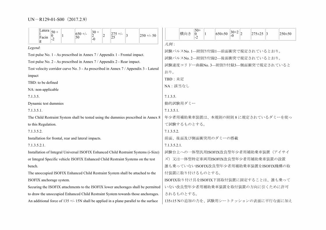
UN-R129-01-S00(2017.2.9)
Lateral Facing
50 + 0 -2
1 650 +/- 50
30 + 2 -0
2 275 +/- 25 3 250 +/- 50
Legend:
Test pulse No. 1 - As prescribed in Annex 7 / Appendix 1 - Frontal impact.
Test pulse No. 2 - As prescribed in Annex 7 / Appendix 2 - Rear impact.
Test velocity corridor curve No. 3 - As prescribed in Annex 7 / Appendix 3 - Lateral
impact
TBD: to be defined
NA: non-applicable
横向き 50+0 -2
1 650±50 30+2 -0 2 275±25 3 250±50
凡例:
試験パルスNo. 1—附則7/付録1—前面衝突で規定されているとおり。
試験パルスNo. 2—附則7/付録2—後面衝突で規定されているとおり。
試験速度コリドー曲線No. 3—附則7/付録3—側面衝突で規定されていると
おり。
TBD:未定
NA:該当なし
7.1.3.5.
Dynamic test dummies
7.1.3.5.
動的試験用ダミー
7.1.3.5.1.
The Child Restraint System shall be tested using the dummies prescribed in Annex 8
to this Regulation.
7.1.3.5.1.
年少者用補助乗車装置は、本規則の附則 8 に規定されているダミーを使っ
て試験するものとする。
7.1.3.5.2.
Installation for frontal, rear and lateral impacts.
7.1.3.5.2.
前面、後面及び側面衝突用のダミーの搭載
7.1.3.5.2.1.
Installation of Integral Universal ISOFIX Enhanced Child Restraint Systems (i-Size)
or Integral Specific vehicle ISOFIX Enhanced Child Restraint Systems on the test
bench.
The unoccupied ISOFIX Enhanced Child Restraint System shall be attached to the
ISOFIX anchorage system.
Securing the ISOFIX attachments to the ISOFIX lower anchorages shall be permitted
to draw the unoccupied Enhanced Child Restraint System towards those anchorages.
An additional force of 135 +/- 15N shall be applied in a plane parallel to the surface
7.1.3.5.2.1.
試験台上への一体型汎用ISOFIX改良型年少者用補助乗車装置(アイサイ
ズ)又は一体型特定車両用ISOFIX改良型年少者用補助乗車装置の設置
誰も乗っていないISOFIX改良型年少者用補助乗車装置をISOFIX機構の取
付装置に取り付けるものとする。
ISOFIX取り付け具をISOFIX下部取付装置に固定することは、誰も乗って
いない改良型年少者用補助乗車装置を取付装置の方向に引くために許可
されるものとする。
135±15 Nの追加の力を、試験用シートクッションの表面に平行な面に加え

UN-R129-01-S00(2017.2.9) of the test seat cushion. The force shall be applied along the centre line of the
Enhanced Child Restraint System and at a height no more than 100 mm above the
cushion.
If present, the top tether shall be adjusted to achieve a tension load of
50 +/- 5N. Alternatively, and if present, the support-leg shall be adjusted according to
the Enhanced Child Restraint System manufacturer's instructions.
The Enhanced Child Restraint System centre line shall be aligned with the centre line
of the test bench.
The dummy shall be placed in the Enhanced Child Restraint System separate from the
seat-back of the chair by a flexible spacer. The spacer shall be 2.5 cm thick and 6 cm
wide. It shall have length equal to the shoulder height less the thigh height, both in the
sitting position and relevant to the dummy size being tested. The resulting height of the
spacer is listed in the table below for the different dummy sizes. The board should
follow as closely as possible the curvature of the chair and its lower end should be at
the height of the dummy's hip joint.
るものとする。その力は、年少者用補助乗車装置の中心線に沿ってクッシ
ョンの上方100 mm以下の高さで、加えるものとする。
トップテザーが存在する場合、それを調節して、50±5 Nの張力荷重を達成
するものとする。代わりに、脚部保護装置が存在する場合は、改良型年少
者用補助乗車装置のメーカーの指示に従って脚部保護装置を調節するも
のとする。
改良型年少者用補助乗車装置中心線は、試験台の中心線に揃えるものとす
る。
ダミーは、フレキシブルスペーサーによって椅子の座席背もたれから分離
された状態で、改良型年少者用補助乗車装置内に配置するものとする。ス
ペーサーは厚さ2.5 cm、幅6 cmとする。その長さは、試験されるダミーサ
イズに関して、着座時の肩の高さから大腿部高さを差し引いたものに等し
くするものとする。下表は、さまざまなダミーのサイズについて、結果と
して得られたスペーサーの高さを示している。このボードは、チェアの湾
曲にできる限りぴったり沿うようにし、下端はダミーの股関節の高さにあ
るべきものとする。
Q0 Q1 Q1.5 Q3 Q6 Q10
(design targets)
Dimensions in mm
Height of spacer device for positioning of dummy
229 +/- 2
237 +/- 2
250 +/- 2
270 +/- 2 359 +/- 2
Adjust the ECRS belt in accordance with the manufacturer's instructions, but to a
Q0 Q1 Q1.5 Q3 Q6 Q10 (設計目標)
寸法単位はmm
ダミー配置用のスペーサー装置の高さ
229±2 237±2 250±2 270±2 359±2
メーカーの指示に従いECRSベルトを調節するが、張力は調節装置の力を
UN-R129-01-S00(2017.2.9) tension of 250 ± 25 N above the adjuster force, with a deflection angle of the strap at
the adjuster of 45 ± 5°, or alternatively, the angle prescribed by the manufacturer.
The spacer shall then be removed and the dummy pushed towards to
the seat back. Distribute the slack evenly throughout the harness.
The longitudinal plane passing through the centre line of the dummy
shall be set midway between the two lower ECRS belt anchorages,
however note shall also be taken of paragraph 7.1.3.2.1.3. above.
After installation, the dummy position shall be adjusted so that:
The dummy centre line and the Enhanced Child Restraint System
centre line shall be aligned exactly with the centre line of the test
bench.
The arms of the dummy shall be positioned symmetrically. Elbows
shall be positioned in such a way that the upper arms are closely
aligned with the sternum.
Hands shall be positioned on the thighs.
Legs shall be positioned parallel to one another or at least
symmetrically.
For lateral impact, positive measures shall be taken to ensure the
stability of the dummy is maintained until t0 and this shall be
confirmed using video analysis. Any means used to stabilise the
dummy before t0 shall not influence the dummy kinematics after t0.
Because the foam of the test bench seat cushion will compress after
installation of the Enhanced Child Restraint System, the dynamic test
250±25 N上回るものとし、調節装置における帯部の偏角を45±5°又はメー
カーの定める角度にする。
その後スペーサーは取り除き、ダミーは座席背もたれの方へ押すものとす
る。ハーネス全体にわたって均等に緩める。
ダミーの中心線を通る縦断面が2つの下部ECRSベルト取付装置の中央に
来るようにセットするものとする。ただし、上記7.1.3.2.1.3項も考慮するも
のとする。
設置後、ダミーの位置は以下のように調節するものとする。
ダミーの中心線と改良型年少者用補助乗車装置の中心線は、試験台の中心
線に正確に揃えるものとする。
ダミーの両腕は対称的に配置するものとする。肘は上腕が胸骨にきっちり
と揃うように配置するものとする。
手は大腿部上に配置されているものとする。
脚は互いに平行に、又は少なくとも対称的に配置するものとする。
側面衝突については、t0までダミーの安定性が維持されるように積極的な
措置をとるものとし、これはビデオ分析を使って確認するものとする。t0
より前にダミーを安定化するために使用される方法は、t0後にダミーの運
動に影響しないものとする。
試験台シートクッションの発泡体は、改良型年少者用補助乗車装置の設置
後に圧縮するので、動的試験は、設置後10分以内に実施するものとする。
試験台シートクッションを回復させるため、同じ試験台シートクッション
を使う2つの試験間の最小時間は20分とする。
腕の位置合わせの例:

UN-R129-01-S00(2017.2.9) shall be conducted no more than 10 minutes after installation.
To allow the test bench seat cushion to recover, the minimum period
between two tests using the same test bench seat cushion shall be 20
minutes.
Example for arm alignment:
7.1.3.6.
Size indication
The dynamic tests shall be conducted with the largest dummy and the smallest
dummy as defined in the following tables according to the size range indicated by
the manufacturer for the Enhanced Child Restraint System.
Table 7: Selection criteria for the dummy according to the range
Size range
indication < 60
60 < x <
75
75 < x <
87 87 < x < 105
105 < x <
135 >135
Dummy Q0 Q1 Q1.5 Q3 Q6 Q10
Where the Enhanced Child Restraint System requires substantial modification for
different sizes (e.g., convertible Child Restraint System) or if the size range cover
7.1.3.6.
アイサイズ表示
動的試験は、改良型年少者用補助乗車装置に関してメーカーから示されて
いるサイズ範囲に従い、下表で定められているように、最大のダミー及び
最小のダミーで実施するものとする。
表 7:範囲に応じたダミーの選択基準
サイズ
範囲の
表示
≦60 60 < x≦75 75 < x≦87 87 < x≦
105 105 < x≦135 >135
ダミー Q0 Q1 Q1.5 Q3 Q6 Q101
1 側面衝突テストに関する Q10 ダミーの傷害基準が規定されるまでは、135
cm を超えるサイズ範囲について側面衝突テストを実施する必要はない。
UN-R129-01-S00(2017.2.9) more than 3 size ranges a relevant intermediate dummy(ies) shall be tested in
addition to the dummy(ies) defined above.
さまざまなサイズに対して、改良型年少者用補助乗車装置にかなりの変更
が必要な場合(たとえば、コンバーチブル型年少者用補助乗車装置)、又
はサイズ範囲が3つのサイズ範囲より多くの範囲をカバーする場合、上記
に定められたダミーに追加して、関連する中間のダミーを試験するものと
する。
7.1.3.6.1.
If the Child Restraint System is designed for two or more children, one test shall be
carried out with the heaviest dummies occupying all seating positions. A second test
with the lightest and the heaviest dummies specified above shall be carried out. The
tests shall be conducted using the test bench as shown in Annex 6, Appendix 3,
Figure 3. The laboratory conducting the tests may, if it deems it advisable, add a
third test with any combination of dummies or empty seat positions.
7.1.3.6.1.
2人以上の幼児用に設計されている年少者用補助乗車装置の場合、すべて
の着座位置に一番重いダミーが置かれた状態で1回目の試験を実施するも
のとする。2回目の試験は、上記で指定されている一番軽いダミーと一番
重いダミーを使って実施するものとする。試験は、附則6、付録3、図3に
示されているとおりの試験台を使って実施するものとする。試験を実施す
る試験施設は、適切と考えられるならば、任意の組み合わせのダミーやダ
ミーなしの座席位置を使用して、3回目の試験を加えてもよい。
7.1.3.6.2.
If the i-Size Child Restraint System uses a top tether, one test shall be carried out
with the smallest dummy with the shorter distance of the top tether (anchorage point
G1). A second test shall be carried out with the heavier dummy with the longer
distance of the top tether (anchorage point G2). Adjust the top tether to achieve a
tension load of 50 +/- 5 N. For side lateral impact the ISOFIX child restraint shall be
tested with only the shorter distance of the top tether.
7.1.3.6.2.
アイサイズ年少者用補助乗車装置がトップテザーを使用する場合、1回目
の試験は、最軽量のダミーを使って、トップテザーの距離を短い方にして
実施するものとする(取付装置ポイントG1)。2回目の試験は、より重い
ダミーを使って、トップテザーの距離を長い方にして実施するものとする
(取付装置ポイントG2)。張力荷重の50±5 Nを達成するようにトップテザ
ーを調節する。側面衝突については、ISOFIX年少者用補助乗車装置は、短
い距離のトップテザーでのみ試験するものとする。
7.1.3.6.3.
If the i-Size Enhanced Child Restraint System uses a support-leg, as an
anti-rotation device the hereafter mentioned dynamic tests shall be
carried out as follows:
7.1.3.6.3.
アイサイズ改良型年少者用補助乗車装置が、回転防止装置として脚部保護
装置を使用する場合、これ以降に述べる動的試験は以下のように実施する
ものとする。
(a) 前面衝突試験は、台車フロアパンの配置に適合する最大調節位置に脚

UN-R129-01-S00(2017.2.9)
(a) The tests for frontal impact shall be conducted with the support-leg adjusted to its
maximum adjustment compatible with the positioning of the trolley floor pan. The
tests for rear impact shall be conducted with the worst case position selected by the
Technical Service. During the tests the support-leg shall be supported by the trolley
floor pan as described in Annex 6, Appendix 2, Figure 2;
(b) In the case of support-legs out of the plane of symmetry, the worst case shall be
selected by the Technical Service for the test;
(c) In the case of "Specific vehicle ISOFIX" category, the support-leg shall be
adjusted as specified by the Child Restraint System manufacturer;
(d) The leg length of a support-leg shall be adjustable in such a way that it is able to
cover the complete span of floor pan levels that are allowed for in Regulation No.16,
Annex 17 for car seats to be approved for the installation i-Size Child Restraints
Systems.
部保護装置を調節して実施するものとする。後面衝突の試験は、技術機関
によって選択された最悪ケースの位置で実施するものとする。試験中、脚
部保護装置は、附則6、付録2、図2に説明されているとおり、台車フロア
パンで支えるものとする。
(b) 脚部保護装置が対称面の外にある場合、技術機関が試験用に最悪ケー
スを選ぶものとする。
(c) 「特定車両用ISOFIX」区分の場合、脚部保護装置を、年少者用補助乗
車装置メーカーが指定するとおりに調節するものとする。
(d) 脚部保護装置のレッグ長は、アイサイズ年少者用補助乗車装置の設置
用に認可される座席について、協定規則第16号、附則17で許可されている
フロアパンのレベルの全範囲をカバーできるように調節可能とするもの
とする。
7.1.3.6.4.
The test specified in paragraph 6.6.4.1.6.2. above is a requirement only for the
largest dummy for which the child restraint is designed.
7.1.3.6.4.
上記 6.6.4.1.6.2 項に指定されている試験は、年少者用補助乗車装置用に設
計されている最大ダミーのみに対する要件である。
7.2.
Testing of individual components
7.2.
個々の構成部品の試験
7.2.1.
Buckle
7.2.1.
バックル
7.2.1.1.
Opening test under load
7.2.1.1.
負荷時にバックルを開く試験
7.2.1.1.1.
A child restraint already having been subjected to the dynamic test specified in
paragraph 7.1.3. above shall be used for this test.
7.2.1.1.1.
本試験には、上記 7.1.3 項に指定されている動的試験を既に受けた年少者
用補助乗車装置を使用するものとする。

UN-R129-01-S00(2017.2.9) 7.2.1.1.2.
The Enhanced Child Restraint System shall be removed from the test bench or the
vehicle without opening the buckle If the buckle is attached to a rigid part, the force
shall be applied reproducing the angle formed between the buckle and that rigid part
during the dynamic test.
7.2.1.1.2.
改良型年少者用補助乗車装置は、バックルを開かずに試験用台車又は車両
から取り外すものとする。バックルには200±2 Nの張力を加えるものとす
る。バックルが剛性部品に取り付けられている場合は、動的試験において
バックルとその剛性部品との間に形成される角度が再現される力を加え
るものとする。
7.2.1.1.3.
A load shall be applied at a speed of 400 +/- 20 mm/min to the geometric centre of
the buckle-release button along a fixed axis running parallel to the initial direction of
motion of the button; the geometric centre applies to that part of the surface of the
buckle to which the release pressure is to be applied. The buckle shall be secured
against a rigid support during the application of the opening force.
7.2.1.1.3.
荷重は400±20 mm/minの速度で、バックル解除ボタンの初めの作動方向に
対して平行な固定軸に沿って、当該ボタンの幾何学的中心に加えるものと
する。幾何学的中心とは、解除力を加えるバックル表面上の部分に相当す
る。バックルに開く力を加えている間、バックルは剛性支持材に固定され
ているものとする。
7.2.1.1.4.
The buckle opening force shall be applied, using a dynamometer or similar device in
the manner and direction of normal use. The contact end shall be a polished metal
hemisphere with radius 2.5 +/- 0.1 mm.
7.2.1.1.4.
バックルを開く力は、通常の方法と方向で、ダイナモメーター又は同様の
装置を使用して加えるものとする。接触端部は半径 2.5±0.1 mm の研磨され
た金属半球とする。
7.2.1.1.5.
The buckle opening force shall be measured and any failure noted.
7.2.1.1.5.
バックルを開く力を測定し、何か故障があれば書き留めるものとする。
7.2.1.2.
Opening test under zero load
7.2.1.2.
無負荷時にバックルを開く試験
7.2.1.2.1.
A buckle assembly which has not previously been subjected to a load shall be
mounted and positioned under a no load condition.
7.2.1.2.1.
負荷を事前に受けたことのないバックルアッセンブリを無負荷状態で取
り付けて、配置するものとする。
7.2.1.2.2.
The method of measuring the buckle opening force shall be as prescribed in
paragraphs 7.2.1.1.3. and 7.2.1.1.4. above.
7.2.1.2.2.
バックルを開く力を測定する方法は、上記 7.2.1.1.3 項及び 7.2.1.1.4 項で規
定されているとおりとする。
UN-R129-01-S00(2017.2.9) 7.2.1.2.3.
The buckle opening force shall be measured.
7.2.1.2.3.
バックルを開く力を測定するものとする。
7.2.1.3.
Strength testing
7.2.1.3.
強度試験
7.2.1.3.1.
For the strength test two samples have to be used. All adjusters, except for adjusters
mounted directly on a child restraint are included in the test.
7.2.1.3.1.
強度試験では、2 個のサンプルを使用する必要がある。年少者用補助乗車
装置に直接装着されている調節装置を除き、すべての調節装置を試験に含
める。
7.2.1.3.2.
Annex 16 shows a typical device for a buckle strength test. The buckle is placed on
the upper round plate (A) within the relief. All adjacent straps have a length of at
least 250 mm and are arranged hanging down from the upper plate respective to their
position at the buckle. The free strap ends are then wound round the lower round
plate (B) until they come out at the plate's inner opening. All straps have to be
vertical between A and B. The round clamping plate (C) is then lightly clamped
against the lower face of (B), still allowing a certain strap movement between them.
With a small force at the tensile machine the straps are tensioned and pulled between
(B) and (C) until all straps are loaded respective to their arrangement. The buckle
shall stay free from plate (A) or any parts at (A) during this operation and the test
itself. (B) and (C) are then clamped firmly together and the tensile force is increased
at a traverse speed of 100 +/- 20 mm/min until the required values are reached.
7.2.1.3.2.
附則16は、バックル強度試験のための典型的な装置を示す。バックルはリ
リーフ内の上部円形プレート(A)上に置く。隣接する帯部はすべて長さ
250 mm以上で、上部プレートから、バックルでのそれぞれの位置に吊り下
がるように配置する。次に、帯部の固定されていない先端を、プレートの
内口から出るようになるまで、下部円形プレート(B)の周りに巻き付け
る。
すべての帯部はAとBの間で垂直にならなければならない。円形締付プレー
ト(C)を、(B)の下面に軽く締め付け、(B)と(C)の間で帯部の動
きがいくらか可能になるようにする。引張機でわずかな力を加え試験ラッ
プに張力をかけ、すべての帯部にそれぞれの配置に応じて荷重がかかるま
で(B)と(C)の間で引っ張る。この操作及び試験中は、バックルは、プ
レート(A)又は(A)のいずれの部品にも接触しないものとする。次に
(B)と(C)を共にしっかりと締め付けて、張力を100±20 mm/minの移動
速度で要求値に達するまで上昇させる。
7.2.2.
Adjusting device
7.2.2.
調節装置
7.2.2.1. 7.2.2.1.

UN-R129-01-S00(2017.2.9) Ease of adjustment 調節のしやすさ
7.2.2.1.1.
When testing a manual adjusting device, the strap shall be drawn steadily through the
adjusting device, having regard for the normal conditions of use, at a rate of 100 +/-
20 mm/min and the maximum force measured to the nearest integer value of N after
the first 25 +/- 5 mm of strap movement.
7.2.2.1.1.
手動調節装置を試験するとき、帯部を、通常の使用状況を考慮しながら、
100±20 mm/minの速度で、最初に帯部が25±5 mm動いた後の最も近い整数
値として測定された最大の力Nで、調節装置を通して絶え間なく引くもの
とする。
7.2.2.1.2.
The test shall be carried out in both directions of strap travel through the device, the
strap being subjected to the full travel cycle 10 times prior to the measurement.
7.2.2.1.2.
試験は、調節装置を通る帯部の両方向で実施し、帯部は、測定の前に、完
全な移動サイクルを 10 回繰り返すものとする。
7.2.3.
Microslip test (see Annex 5, Figure 3)
7.2.3.
マイクロスリップ試験(附則 5 の図 3 参照)
7.2.3.1.
The components or devices to be subjected to the microslip test shall be kept for a
minimum of 24 hours before testing in an atmosphere having a temperature of 20
deg. C +/- 5 deg. C and a relative humidity of 65 +/- 5 per cent. The test shall be
carried out at a temperature between 15 deg. C and 30 deg. C.
7.2.3.1.
マイクロスリップ試験を受ける構成部品又は装置は、試験前に温度20℃
±5℃及び相対湿度65±5%の大気中で、最低24時間保持するものとする。試
験は15℃から30℃の間で実施するものとする。
7.2.3.2.
The free end of the strap shall be arranged in the same configuration as when the
device is in use in the vehicle, and shall not be attached to any other part.
7.2.3.2.
帯部の固定しない先端部は、当該装置を車両内で使用する場合と同じ形態
で配置するものとし、その他の部分には取り付けないものとする。
7.2.3.3.
The adjusting device shall be placed on a vertical piece of strap one end of which
bears a load of 50 +/- 0.5 N (guided in a manner which prevents the load from
swinging and the strap from twisting). The free end of the strap from the adjusting
device shall be mounted vertically upwards or downwards as it is in the vehicle. The
other end shall pass over a deflector roller with its horizontal axis parallel to the
plane of the section of strap supporting the load, the section passing over the roller
7.2.3.3.
調節装置を帯部の垂直片上に配置し、その帯部の一方の端部が50±0.5 Nの
負荷に耐えるものとする(荷重が揺動したり帯部がよじれたりしない方法
で誘導する)。調節装置からの固定されない帯部の先端は、車両内と同じ
ように、上向き又は下向きに垂直に取り付けるものとする。他方の端部は
ディフレクターローラーに掛け、当該ローラーの水平軸は荷重を支える帯
部の断面に平行で、当該ローラーを通る帯部断面が水平になるようにする

UN-R129-01-S00(2017.2.9) being horizontal. ものとする。
7.2.3.4.
The device being tested shall be arranged in such a way that its centre, in the highest
position to which it can be raised, is 300 +/- 5 mm from a support table, and the load
of 50 N shall be 100 +/- 5 mm from that support table.
7.2.3.4.
試験中の装置は、その中心が、持ち上げることのできる最も高い位置で、
支持台から300±5 mmの高さになるように配置し、50 Nの荷重をその支持台
から100±5 mmのところに加えるものとする。
7.2.3.5.
20 +/- 2 pre-test cycles shall then be completed and 1,000 +/- 5 cycles shall then be
completed at a frequency of 30 +/- 10 cycles per minute, the total amplitude being
300 +/- 20 mm or as specified in paragraph 7.2.5.2.6.2. above. The 50 N load shall
be applied only during the time corresponding to a shift of 100 +/- 20 mm for each
half period. Microslip shall be measured from the position at the end of the 20
pre-test cycles.
7.2.3.5.
20±2の予備試験サイクルを完了し、その後、毎分30±10サイクルの頻度で、
1,000±5サイクルを完了するものとする。振幅合計は300±20 mm又は上記
7.2.5.2.6.2項に指定されているとおりとする。50 Nの荷重は各半周期につき
100±20 mmの移動に対応する時間内に限って加えるものとする。マイクロ
スリップは20回の予備試験サイクルの終了時の位置から測定するものと
する。
7.2.4.
Retractor
7.2.4.
巻取装置
7.2.4.1.
Retracting force
7.2.4.1.
巻取り力
7.2.4.1.1.
The retracting forces shall be measured with the ECRS belt assembly, fitted to a
dummy as for the dynamic test prescribed in paragraph 7.1.3. above. The strap
tension shall be measured at the point of contact with (but just clear of) the dummy
while the strap is being retracted at the approximate rate of 0.6 m/min.
7.2.4.1.1.
巻取り力は、座席ベルトアッセンブリを上記7.1.3項で規定されている動的
試験の場合と同じようにダミーに取り付けて、測定するものとする。帯部
の張力は、帯部が約0.6 m/minの速度で巻き取られている間に、ダミーと接
触する点(ただしわずかに隙間を持たせて)で測定するものとする。
7.2.4.2.
Durability of retractor mechanism
7.2.4.2.
巻取装置メカニズムの耐久性
7.2.4.2.1.
The strap shall be withdrawn and allowed to retract for the required number of cycles
at a rate of not more than 30 cycles per minute. In the case of emergencylocking
7.2.4.2.1.
帯部を毎分30サイクル以下の速度で所用サイクル数だけ、引き出して巻き
取ることができるものとする。緊急ロック式巻取装置の場合には、巻取装
UN-R129-01-S00(2017.2.9) retractors, a jolt to lock the retractor shall be introduced at each fifth cycle. The jolts
occur in equal numbers at each of five different extractions, namely, 90, 80, 75, 70
and 65 per cent of the total length of the strap on the retractor. However, where the
length of the strap exceeds 900 mm the above percentage shall be related to the final
900 mm of strap which can be withdrawn from the retractor.
置をロックするために5サイクルごとに衝撃を与えるものとする。この衝
撃は、帯部を引き出す長さを5回変えて、すなわち巻取装置の帯部の全長
の90、80、75、70及び65%の長さでそれぞれ同じ回数発生させるものとす
る。ただし、帯部の長さが900 mmを超える場合には、上記のパーセンテー
ジは、巻取装置から引き出すことのできる帯部の最後の900 mmの部分に対
するものとする。
7.2.4.3.
Locking of emergency-locking retractors
7.2.4.3.
緊急ロック式巻取装置のロック
7.2.4.3.1.
The retractor shall be tested once for locking, when the strap has been unwound to its
full length less 300 +/- 3 mm.
7.2.4.3.1.
巻取装置には、帯部の全長より300±3 mm短い長さまで引き出されたとき
に、1回のロック試験を実施するものとする。
7.2.4.3.2.
In the case of a retractor actuated by strap movement, the extraction shall be in the
direction in which it normally occurs when the retractor is installed in a vehicle.
7.2.4.3.2.
帯部の動きで作動する巻取装置の場合には、引き出し方向は、巻取装置が
車両内に取り付けられているときに通常作動する方向とする。
7.2.4.3.3.
When retractors are being tested for sensitivity to vehicle accelerations, they shall be
tested at the above extraction length in both directions along two mutually
perpendicular axes which are horizontal if the retractors are to be installed in a
vehicle as specified by the child restraint manufacturer. When this position is not
specified, the testing authority shall consult the child restraint manufacturer. One of
these test directions shall be chosen by the Technical Service conducting the
approval tests to give the most adverse conditions with respect to actuation of the
locking mechanism.
7.2.4.3.3.
巻取装置を車両の加速度に対する感度について試験する場合、当該巻取装
置を年少者用補助乗車装置のメーカーの定めるとおりに車両内に取り付
けることになっている場合に、水平になる、互いに直角な2本の軸に沿っ
て、両方向に上記の長さまで引き出して試験するものとする。この位置が
指定されていない場合、試験当局は年少者用補助乗車装置のメーカーに照
会するものとする。これらの試験方向の1つは、ロッキングメカニズムの
作動について最も不利な条件を与えるように、認可試験を行う技術機関が
選択するものとする。
7.2.4.3.4.
The design of the apparatus used shall be such that the required acceleration is given
at an average rate of increase of acceleration of at least 25 g/s.3
7.2.4.3.4.
使用する装置の設計は、所要加速度が、少なくとも平均25 g/sの加速度上昇
率で達成されるようにするものとする。3

UN-R129-01-S00(2017.2.9) 3 g = 9.81 m/s2. 3 g = 9.81 m/s2
7.2.4.3.5.
For testing compliance with the requirements of paragraphs 6.7.3.2.1.3. and
6.7.3.2.1.4. above the retractor shall be mounted on a horizontal table and the table
tilted at a speed not exceeding 2 deg. per second until locking has occurred. The test
shall be repeated with tilting in other directions to ensure that the requirements are
fulfilled.
7.2.4.3.5.
上記6.7.3.2.1.3項と6.7.3.2.1.4項の要件への適合を確認する試験について
は、巻取装置を水平のテーブル上に取り付け、そのテーブルをロックが発
生するまで毎秒2°以下の速度で傾けるものとする。この試験は他の方向に
も傾けて繰り返し、要件が満たされることを確認するものとする。
7.2.4.4.
Corrosion testing
7.2.4.4.
腐食試験
7.2.4.4.1.
The corrosion testing shall be carried out as paragraph 7.1.1. above.
7.2.4.4.1.
腐食試験は上記 7.1.1 項に記載されているとおりに実施するものとする。
7.2.4.5.
Dust resistance testing
7.2.4.5.
耐粉塵試験
7.2.4.5.1.
The retractor shall be positioned in a test chamber as described in Annex 3 to this
Regulation. It shall be mounted in an orientation similar to that in which it is
mounted in the vehicle. The test chamber shall contain dust as specified in paragraph
7.2.4.5.2. below. A length of 500 mm of the strap shall be extracted from the
retractor and kept extracted, except that it shall be subjected to 10 complete cycles of
retraction and withdrawal within one or two minutes after each agitation of the dust.
For a period of five hours, the dust shall be agitated every 20 minutes for five
seconds by compressed air free of oil and moisture at a gauge pressure of 5.5 +/- 0.5
bars entering through an orifice 1.5 +/- 0.1 mm in diameter.
7.2.4.5.1.
巻取装置を本規則の附則3で説明されている試験チャンバに置くものとす
る。それは車両内に取り付ける場合と同様の向きに取り付けるものとす
る。試験チャンバには下記7.2.4.5.2項に定める粉塵を入れるものとする。
500 mmの長さの帯部を巻取装置から引き出してそのまま保持するものと
する。ただし、粉塵を攪拌する度にその後1分又は2分以内に10サイクルの
引き出しと巻取りを完全に行うものとする。粉塵は、5時間にわたり20分
ごとに5秒間、直径1.5±0.1 mmのオリフィスから5.5±0.5バールのゲージ圧力
で油分と湿気のない圧縮空気を吹き込んで、攪拌するものとする。
7.2.4.5.2.
The dust used in the test described in paragraph 7.2.4.5.1. above shall consist of
about 1 kg of dry quartz. The particle size distribution shall be as follows:
7.2.4.5.2.
上記7.2.4.5.1項で説明した試験に使用する粉塵は、約1 kgの乾燥石英から成
るものとする。粒子の大きさの配分は次のとおりとする。
UN-R129-01-S00(2017.2.9) (a) Passing 150 micrometres aperture, 104 micrometres wire diameter: 99 to 100 per
cent;
(b) Passing 105 micrometres aperture, 64 micrometres wire diameter: 76 to 86 per
cent;
(c) Passing 75 micrometres aperture, 52 micrometres wire diameter: 60 to 70 per
cent.
(a) 口径150 μm、ワイヤ直径104 μmを通過:99から100%、
(b) 口径105 μm、ワイヤ直径64 μmを通過:76から86%、
(c) 口径 75 μm、ワイヤ直径 52 μm を通過:60 から 70%。
7.2.5.
Static test for straps
7.2.5.
帯部の静的試験
7.2.5.1.
Strap strength test
7.2.5.1.
帯部の強度試験
7.2.5.1.1.
Each test shall be carried out on two new samples of strap, conditioned as specified
in paragraph 6.7.4. of this Regulation
7.2.5.1.1.
各試験は、本規則の 6.7.4 項に指定されているとおりにコンディショニン
グを施した 2 つの新しい帯部の供試品で実施するものとする。
7.2.5.1.2.
Each strap shall be gripped between the clamps of a tensile strength-testing machine.
The clamps shall be so designed as to avoid breakage of the strap at or near them.
The speed of traverse shall be 100 +/- 20 mm/min. The free length of the specimen
between the clamps of the machine at the start of the test shall be 200 mm +/- 40
mm.
7.2.5.1.2.
各帯部は、張力強度試験機のクランプ間に挟むものとする。クランプはそ
の中また近くで帯部が破断しないように設計されているものとする。移動
速度は100±20 mm/minとする。試験開始時の試験機のクランプ間の供試体
の自由長は200 mm±40 mmとする。
7.2.5.1.2.1.
The tension shall be increased until the strap breaks and the breaking load noted.
7.2.5.1.2.1.
張力を帯部が破断するまで増加し、破断荷重を記録するものとする。
7.2.5.1.3.
If the strap slips or breaks at or within 10 mm of either of the clamps, the test shall
be invalid and a new test shall be carried out on another specimen.
7.2.5.1.3.
帯部がどちらかのクランプから 10 mm 以内の部分で滑るか破断した場合
は、試験を無効とし、新たに別の供試品で試験を実施するものとする。
7.2.5.2.
Samples out from straps, as referred to in paragraph 3.2.3. of this Regulation, shall
7.2.5.2.
本規則の 3.2.3 項で言及されているように、帯部から切り取った供試片は、
UN-R129-01-S00(2017.2.9) be conditioned as follows: 次のようにコンディショニングを施すものとする。
7.2.5.2.1.
Room conditioning
7.2.5.2.1.
室内コンディショニング
7.2.5.2.1.1.
The strap shall be kept for 24 +/- 1 hours in an atmosphere having a temperature of
23 deg. C +/- 5 deg. C and a relative humidity of 50 +/- 10 per cent. If the test is not
carried out immediately after conditioning, the specimen shall be placed in a
hermetically closed receptacle until the test begins. The breaking load shall be
determined within five minutes after removal of the strap from the conditioning
atmosphere or from the receptacle.
7.2.5.2.1.1.
帯部を24±1時間、温度23℃±5℃、相対湿度50±10%の大気中で保持するも
のとする。試験がコンディショニング直後に実施されない場合には、供試
片を試験が始まるまで密封容器内に置くものとする。破断荷重は、コンデ
ィショニング大気又は容器から帯部を取り出した後、5分以内に測定する
ものとする。
7.2.5.2.2.
Light conditioning
7.2.5.2.2.
光暴露コンディショニング
7.2.5.2.2.1.
The provisions of Recommendation ISO/105-B02 (1978), shall apply. The strap shall
be exposed to light for the time necessary to produce fading of Standard Blue Dye
No. 7 to a contrast equal to Grade 4 on the grey scale.
7.2.5.2.2.1.
ISO/105-B02 (1978)勧告の規定を適用するものとする。帯部は、標準青色染
料No. 7がグレースケールの等級4に等しい明暗差まで褪色するのに必要な
時間の間、光に暴露するものとする。
7.2.5.2.2.2.
After exposure, the strap shall be kept for a minimum of 24 hours in an atmosphere
having a temperature of 23 deg. C + 5 deg. C and a relative humidity of 50 +/- 10 per
cent. The breaking load shall be determined within five minutes after the removal of
the strap from the conditioning installation.
7.2.5.2.2.2.
暴露の後、帯部を最低24時間、温度23℃+5℃、相対湿度50±10%の大気中
で保持するものとする。破断荷重は、コンディショニング設備から帯部を
取り出した後、5分以内に測定するものとする。
7.2.5.2.3.
Cold conditioning
7.2.5.2.3.
低温コンディショニング
7.2.5.2.3.1.
The strap shall be kept for a minimum of 24 hours in an atmosphere having a
temperature of 23 deg. C +/- 5 deg. C and a relative humidity of 50 +/- 10 per cent.
7.2.5.2.3.1.
帯部を最低 24 時間、温度 23℃±5℃、相対湿度 50±10%の大気中で保持する
ものとする。

UN-R129-01-S00(2017.2.9) 7.2.5.2.3.2.
The strap shall then be kept for 90 +/- 5 minutes on a plain surface in a
low-temperature chamber in which the air temperature is -30 deg. C +/- 5 deg. C. It
shall then be folded and the fold shall be loaded with a weight of 2 +/- 0.2 kg
previously cooled to -30 deg. C +/- 5 deg. C. When the strap has been kept under
load for 30 +/- 5 minutes in the same low-temperature chamber, the weight shall be
removed and the breaking load shall be measured within five minutes after removal
of the strap from the low-temperature chamber.
7.2.5.2.3.2.
次に帯部を90±5分間、気温-30℃±5℃の低温室の平らな表面上で保持するも
のとする。次に帯部を折り畳み、その上にあらかじめ-30℃±5℃に冷やした
2±0.2 kgのウェイトで荷重を加えるものとする。同じ低温室内で30±5分間、
帯部に荷重を加え続けた後に、ウェイトを取り除くものとし、低温室から
帯部を取り出した後、5分以内に破断荷重を測定するものとする。
7.2.5.2.4.
Heat conditioning
7.2.5.2.4.
高温コンディショニング
7.2.5.2.4.1.
The strap shall be kept for 180 +/- 10 minutes in a heating-cabinet atmosphere
having a temperature of 60 deg. C +/- 5 deg. C and a relative humidity 65 +/- 5 per
cent.
7.2.5.2.4.1.
帯部を 180±10 分間、温度 60℃±5℃、相対湿度 65±5%の加熱キャビネット
の大気中に保持するものとする。
7.2.5.2.4.2.
The breaking load shall be determined within five minutes after removal of the strap
from the heating cabinet.
7.2.5.2.4.2.
帯部を加熱キャビネットから取り出した後、5 分以内に破断荷重を測定す
るものとする。
7.2.5.2.5.
Exposure to water
7.2.5.2.5.
水に対する暴露
7.2.5.2.5.1.
The strap shall be kept fully immersed for 180 +/- 10 minutes in distilled water, at a
temperature of 20 deg. C +/- 5 deg. C, to which a trace of wetting agent has been
added. Any wetting agent suitable for the fibre being tested may be used.
7.2.5.2.5.1.
帯部を 180±10 分間、微量の湿潤剤を添加した温度 20℃±5℃の蒸留水内に
完全に浸漬するものとする。試験する繊維に適したものであればどの湿潤
剤を使用してもよい。
7.2.5.2.5.2.
The breaking load shall be determined within 10 minutes after removal of the strap
from the water.
7.2.5.2.5.2.
帯部を水から取り出した後、10 分以内に破断荷重を測定するものとする。
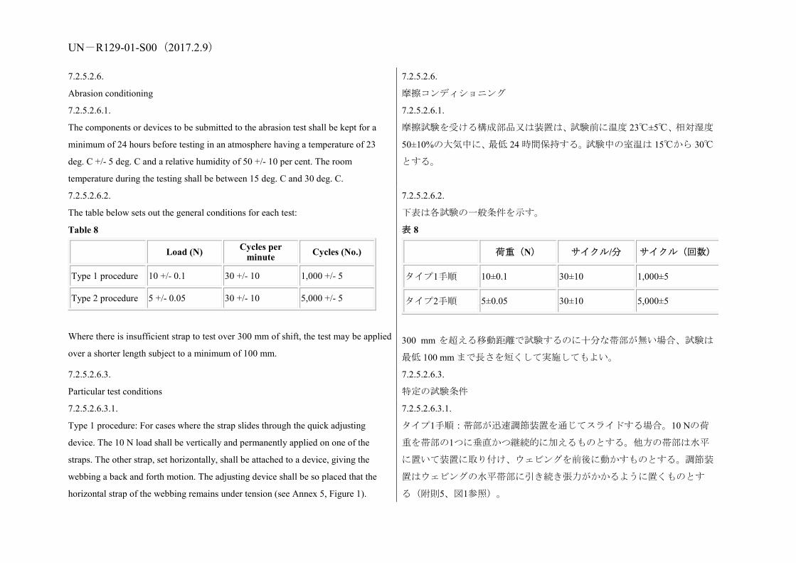
UN-R129-01-S00(2017.2.9) 7.2.5.2.6.
Abrasion conditioning
7.2.5.2.6.
摩擦コンディショニング
7.2.5.2.6.1.
The components or devices to be submitted to the abrasion test shall be kept for a
minimum of 24 hours before testing in an atmosphere having a temperature of 23
deg. C +/- 5 deg. C and a relative humidity of 50 +/- 10 per cent. The room
temperature during the testing shall be between 15 deg. C and 30 deg. C.
7.2.5.2.6.1.
摩擦試験を受ける構成部品又は装置は、試験前に温度 23℃±5℃、相対湿度
50±10%の大気中に、最低 24 時間保持する。試験中の室温は 15℃から 30℃
とする。
7.2.5.2.6.2.
The table below sets out the general conditions for each test:
Table 8
Load (N) Cycles per minute Cycles (No.)
Type 1 procedure 10 +/- 0.1 30 +/- 10 1,000 +/- 5
Type 2 procedure 5 +/- 0.05 30 +/- 10 5,000 +/- 5
Where there is insufficient strap to test over 300 mm of shift, the test may be applied
over a shorter length subject to a minimum of 100 mm.
7.2.5.2.6.2.
下表は各試験の一般条件を示す。
表 8
荷重(N) サイクル/分 サイクル(回数)
タイプ1手順 10±0.1 30±10 1,000±5
タイプ2手順 5±0.05 30±10 5,000±5
300 mm を超える移動距離で試験するのに十分な帯部が無い場合、試験は
最低 100 mm まで長さを短くして実施してもよい。
7.2.5.2.6.3.
Particular test conditions
7.2.5.2.6.3.
特定の試験条件
7.2.5.2.6.3.1.
Type 1 procedure: For cases where the strap slides through the quick adjusting
device. The 10 N load shall be vertically and permanently applied on one of the
straps. The other strap, set horizontally, shall be attached to a device, giving the
webbing a back and forth motion. The adjusting device shall be so placed that the
horizontal strap of the webbing remains under tension (see Annex 5, Figure 1).
7.2.5.2.6.3.1.
タイプ1手順:帯部が迅速調節装置を通じてスライドする場合。10 Nの荷
重を帯部の1つに垂直かつ継続的に加えるものとする。他方の帯部は水平
に置いて装置に取り付け、ウェビングを前後に動かすものとする。調節装
置はウェビングの水平帯部に引き続き張力がかかるように置くものとす
る(附則5、図1参照)。

UN-R129-01-S00(2017.2.9) 7.2.5.2.6.3.2.
Type 2 procedure: For cases where the strap changes direction in passing through a
rigid part. During this test, the angles of both webbing straps shall be as shown in
Annex 5, Figure 2. The 5 N load shall be permanently applied. For cases where the
strap changes direction more than once in passing through a rigid part, the load of 5
N may be increased so as to achieve the prescribed 300 mm of strap movement
through that rigid part.
7.2.5.2.6.3.2.
タイプ2手順:帯部が剛性部分を通過するときに方向を変える場合。本試
験中は、両方のウェビング帯部の角度は附則5の図2に示すとおりとする。
5 Nの荷重を継続的に加えるものとする。帯部が剛性部分を通過するとき2
回以上方向を変える場合には、剛性部分を通る帯部の移動が規定どおり
300 mmになるように、5 Nの荷重を増やしてもよい。
7.2.6.
Conditioning test for adjusters mounted directly on a child restraint
Install the largest dummy for which the restraint is intended, as if for the dynamic
test, including the standard slack as specified in paragraph 7.1.3.5. above. Mark a
reference line on the webbing where the free end of the webbing enters the adjuster.
Remove the dummy and place the restraint in the conditioning rig shown in Figure 1,
Annex 15.
The webbing shall be cycled for a total distance of not less than 150 mm through the
adjuster. This movement shall be such that at least 100 mm of webbing on the side of
the reference line towards the free end of the webbing and the remainder of the
moving distance (approx. 50 mm) on the integral harness side of the reference line
moves through the adjuster.
If the length of webbing from the reference line to the free end of the webbing is
insufficient for the movement described above, the 150 mm of movement through
the adjuster shall be from the fully extended harness position.
The frequency of cycling shall be 10 +/- 1 cycles/minute, with a velocity on "B" of
150 +/- 10 mm/sec.
7.2.6.
年少者用補助乗車装置に直接装着する調節装置のコンディショニング試
験
当該拘束装置の対象となる最大のダミーを、上記7.1.3.5項に指定されてい
るとおりの標準のたるみを含めて、動的試験の場合と同様に取り付ける。
ウェビングの固定されない先端が調節装置に入るところで、ウェビング上
に基準線をマークする。
ダミーを取り除き、拘束装置を附則15の図1に示すコンディショニング装
置内に置く。
ウェビングは調節装置を通して総距離150 mm以上にわたってサイクルす
るものとする。この動きは、基準線からウェビングの固定されていない先
端に向かう側が少なくとも100 mm、基準線から一体型ハーネス側への残り
の移動距離(約50 mm)が調節装置を通って動くものとする。
基準線からウェビングの固定されない先端までのウェビングの長さが上
記の動作をするのに不十分な場合には、調節装置を通した150 mmの移動
は、ハーネスを完全に伸ばした位置から行うものとする。
このサイクルの頻度は、1 分当たり 10±1 サイクルとし、「B」上の速度は
150±10 mm/秒とする。
7.2.7. 7.2.7.

UN-R129-01-S00(2017.2.9) Temperature test 温度試験
7.2.7.1.
The components specified in paragraph 6.6.5.1. above shall be exposed to an
environment over a water surface within a closed space, the environment having a
temperature of not less than 80 deg. C, for a continuous period of not less than 24
hours and then cooled in an environment having a temperature not exceeding 23 deg.
C. The cooling period shall immediately be followed by three consecutive 24 hour
cycles with each cycle comprising the following consecutive sequences:
(a) An environment having a temperature of not less than 100 deg. C shall be
maintained for a continuous period of 6 hours and this environment shall be attained
within 80 minutes of commencement of the cycle; then
(b) An environment having a temperature of not more than 0 deg. C shall be
maintained for a continuous period of 6 hours and this environment shall be attained
within 90 minutes; then
(c) An environment having a temperature of not more than 23 deg. C shall be
maintained during the remainder of the 24 hour cycle.
7.2.7.1.
上記6.6.5.1項に指定された構成部品は、閉ざされた空間の中で、水面上の
環境にさらすものとする。この環境は、24時間以上にわたって連続して
80℃以上の温度にしてから、23℃以下の温度で冷却する。冷却期間の直後
には、1サイクルが以下の連続手順により構成される、24時間サイクルを3
回繰り返すものとする。
(a) 100℃以上の温度の環境を連続6時間維持するものとし、この環境はサイ
クルの開始80分以内に達成するものとする。次に、
(b) 0℃以下の温度の環境を連続6時間維持するものとし、この環境は90分以
内に達成するものとする。次に、
(c) 23℃以下の温度の環境を当該24時間サイクルの残りの時間にわたって
維持するものとする。
7.2.8.
The complete seat, or the component fitted with ISOFIX attachments (e.g. ISOFIX
base) if it has a release button, is attached rigidly to a test rig in such a way that
ISOFIX connectors are vertically aligned as shown in Figure 3. A 6 mm diameter
bar, 350 mm long, shall be attached to the ISOFIX connectors. A mass of 5 kg shall
be attached to the extremities of the bar.
7.2.8.
シート全体、またはISOFIX取り付け具(例えばISOFIXベース)を取り付
けた構成部品は、解除ボタンがある場合、ISOFIX コネクタが図3に示すよ
うに垂直に並ぶようにしてテストリグにしっかりと固定する。直径6 mm、
長さ350 mmのバーをISOFIXコネクタに取り付けるものとする。5 kgの質量
をバーの先端に取り付けるものとする。
7.2.8.1.
An opening force shall be applied to the release button or handle along a fixed axis
running parallel to the initial direction of motion of the button/handle; the geometric
centre applies to that part of the surface of the ISOFIX attachment to which the
7.2.8.1.
ボタン/ハンドルの初めの作動方向に対して平行な固定軸に沿って解除
ボタンまたはハンドルに開ける力を加えるものとする。ISOFIX取り付け具
の表面の解除圧力を加える部分が幾何学的中心となる。
UN-R129-01-S00(2017.2.9) release pressure is to be applied.
7.2.8.2.
The ISOFIX attachment opening force shall be applied using a dynamometer or
similar device in the normal manner and direction as indicated in the manufacturers
user manual. The contact end shall be a polished metal hemisphere with radius 2.5 ±
0.1 mm for a release button or a polished metal hook with a radius of 25 mm.
7.2.8.2.
ISOFIX取り付け具を開ける力は、メーカーのユーザーマニュアルに記載さ
れた通常の方法と方向で、ダイナモメーターまたは同様の装置を使用して
加えるものとする。接触端部は、解除ボタンについては半径2.5±0.1 mmの
研磨した金属半球、または半径25 mmの研磨した金属フックとする。
7.2.8.3.
If the design of the child restraint prevents the application of the procedure described
in paragraphs 7.2.8.1. and 7.2.8.2., an alternative method may be applied with the
agreement of the Technical Service carrying out the test.
7.2.8.3.
年少者用補助乗車装置の設計によって、7.2.8.1項および7.2.8.2項に記載し
た手順が実施できない場合は、テストを実施する技術機関の同意を得て代
替の方法を使用することができる。
7.2.8.4.
The ISOFIX attachment opening force to be measured shall be that needed to
disengage the first connector.
7.2.8.4.
測定対象となる ISOFIX 取り付け具を開ける力は、最初のコネクタを外す
ために必要な力とする。
7.2.8.5.
The test shall be carried out on a new seat, and repeated on a seat that has been
subjected to the cycling procedure specified in paragraph 6.7.5.1.
Fig. 3
7.2.8.5.
テストは新しいシートで実施し、6.7.5.1項に規定したサイクル手順を実施
したシートを使って繰り返すものとする。
図.3

UN-R129-01-S00(2017.2.9)
7.3.
Certification of test bench cushion.
7.3.
試験台クッションの検定
7.3.1.
The test bench seat cushion shall be certified when new to establish initial values for
impact penetration and peak deceleration, and then after every 50 dynamic tests or at
least every month, whichever is the sooner, or before each test if the test rig is used
frequently.
7.3.1.
試験台シートクッションは、未使用時に衝突侵入度とピーク減速度の初期
値を求めるために検定を行い、その後50回の動的試験が終わるごとか、又
は少なくとも毎月のいずれか早いほうに、あるいは試験装置を頻繁に使う
場合には各試験前に検定を行うものとする。
7.3.2.
The certification and measuring procedures shall correspond to those specified in the
latest version of ISO 6487; the measuring equipment shall correspond to the
specification of a data channel with a channel filter class (CFC) 60.
Using the test device defined in Annex 14 to this Regulation, conducts three tests,
150 +/- 5 mm from the front edge of the cushion on the centre line and at 150 +/- 5
mm in each direction from the centre line.
7.3.2.
検定及び測定の手順は、ISO 6487の最新版に定めるところによるものとす
る。測定装置は、チャンネルフィルタークラス(CFC)60の計測チャンネ
ルの仕様に相当するものとする。
本規則の附則14に定める試験装置を用い、中心線上のクッションの前端か
ら150±5 mm、及び中心線から各方向に150±5 mmのところで3回試験を実施
する。
UN-R129-01-S00(2017.2.9) Place the device vertically on a flat rigid surface. Lower the impact mass until it
contacts the surface and set the penetration marker to the zero position. Place the
device vertically above the test point, raise the mass 500 +/- 5 mm and allow it to fall
freely to make impact on the test bench seat cushion surface. Record the penetration
and the deceleration curve.
装置を平らで固い表面上に垂直に置く。衝突用の重りをこの表面に接触す
るまで下げ、侵入マーカーをゼロ位置に設定する。装置を測定点の上に垂
直に置き、重りを500±5 mm持ち上げ、自由落下させて試験台シートクッシ
ョン表面に衝突させる。侵入度及び減速曲線を記録する。
7.3.3.
The peak values recorded shall not deviate by more than 15 per cent from the initial
values.
7.3.3.
記録されたピーク値は、初期値より 15%を超える偏差がないものとする。
7.4.
Registration of dynamic behaviour
7.4.
動的挙動の記録
7.4.1.
In order to determine the behaviour of the dummy and its displacements, all dynamic
tests shall be registered according to the following conditions:
7.4.1.
ダミーの挙動と移動量を決定するために、すべての動的試験は以下の条件
に従って記録するものとする。
7.4.1.1.
Filming and recording conditions:
(a) The frequency shall be at least 1,000 frames per second;
(b) The test shall be recorded on video or digital data carrier over at least the first
300 ms.
7.4.1.1.
撮影及び録画条件
(a) 撮影速度は1秒当たり少なくとも1,000フレームとする。
(b) 試験は、少なくとも最初の 300 ms にわたり、ビデオ又はデジタルデー
タキャリアに録画するものとする。
7.4.1.2.
Estimation of uncertainty:
Testing laboratories shall have and shall apply procedures for estimating uncertainty
of measurement of the displacement of the dummy's head. The uncertainty shall be
within +/- 25 mm..
Examples of international standards of such procedure are EA-4/02 of the European
Accreditation Organization or ISO 5725:1994 or the General Uncertainty
Measurement (GUM) method.
7.4.1.2.
不確かさの推定
試験機関は、ダミー頭部の移動量の測定の不確かさを推定するための手順
を確保し、これを適用するものとする。不確かさは、±25 mm以内とする。
かかる手順の国際基準の例には、欧州認定機関の EA-4/02 又は ISO
5725:1994 又は一般的不確かさ測定(GUM)法などがある。

UN-R129-01-S00(2017.2.9) 7.5.
The measuring procedures shall correspond to those defined in the latest version of
ISO 6487. The channel frequency class shall be:
Table 9
Type of measurement CFC(FH) Cut-off frequency (FN)
Trolley acceleration 600 see ISO 6487Annex A
Belt loads 600 see ISO 6487Annex A
Chest acceleration 600 see ISO 6487Annex A
Head acceleration 1,000 1,650 Hz
Upper neck force 600
Upper neck moment 600
Chest deflection 600
Abdominal pressure 1800
The sampling rate should be a minimum of 10 times the channel frequency class (i.e.
in installations with channel frequency class of 1,000, this corresponds to a minimum
sampling rate of 10,000 samples per second per channel).
7.5.
測定手順は、ISO 6487の最新バージョンで規定されているものに一致する
ものとする。チャンネル周波数等級は以下のとおりとする。
表 9
測定の種類 CFC(FH) カットオフ周波数(FN)
台車加速度 60 ISO 6487附則Aを参照
ベルト荷重 60 ISO 6487附則Aを参照
胸部加速度 180 ISO 6487附則Aを参照
頭部加速度 1,000 1,650 Hz
上頸部力 1,000
上頸部モーメント 600
胸部たわみ 600
腹部圧力 180
サンプル率は、少なくともチャンネル周波数等級の10倍であるべきものと
する(すなわち、チャンネル周波数等級が1,000である設備の場合、これは
チャンネル当たり1秒につき10,000サンプルの最低サンプル率に相当す
る)。
8. Test reports of type approval and of production qualification 8. 型式認可と生産認定の試験成績書
8.1.
The test report shall record the results of all tests and measurements including the
following test data:
(a) The type of device used for the test (acceleration or deceleration device);
8.1.
試験成績書には、以下の試験データを含む、すべての試験及び測定結果を
記録するものとする。
(a) 試験で使用した装置の種類(加速又は減速装置)、

UN-R129-01-S00(2017.2.9) (b) The total velocity change;
(c) The trolley speed immediately before impact only for deceleration sleds;
(d) The acceleration or deceleration curve during all the velocity change of the
trolley and at least 300 ms;
(e) The time (in ms) when the head of the dummy reaches its maximum
displacement during the performance of the dynamic test;
(f) The place occupied by the buckle during the tests, if it can be varied;
(g) Any failure or breakage;
(h) The following dummy criteria: HIC, Head Acceleration 3 ms, Upper Neck
Tension Force, Upper Neck Moment, Thorax Chest Deflection; Abdominal Pressure
(in frontal impact).
(b) 総速度変化、
(c) 減速式スレッドの場合のみ、衝突直前の台車速度、
(d) 台車のすべての速度変化の間及び少なくとも300 ms間における加速度
又は減速度曲線、
(e) 動的試験の実施中にダミーの頭部移動が最大に達するときの時間(単
位ms)、
(f) 試験中のバックルの占める位置が変わる場合はその位置、
(g) 故障又は破損、
(h) 次のダミー基準:HIC、頭部加速度3 ms、上頸部引張力、上頸部モーメ
ント、胸部たわみ、腹部圧力(前面衝突の場合)
8.2.
If provisions relating to anchorages contained in Annex 6, Appendix 3, to this
Regulation have not been respected, the test report shall describe how the child
restraint is installed and shall specify important angles and dimensions.
8.2.
本規則の附則 6、付録 3 に含まれている取付装置に関する規定を考慮して
いない場合、試験成績書に年少者用補助乗車装置の取り付け方法を説明
し、重要な角度と寸法を明記するものとする。
8.3.
When the child restraint is tested in a vehicle or vehicle structure, the test report shall
specify the manner of attaching the vehicle structure to the trolley, the position of the
Child Restraint System and vehicle seat and the inclination of the vehicle seat-back.
8.3.
車両又は車両構造で年少者用補助乗車装置を試験する場合には、試験成績
書に、車両構造の台車への取り付け方法、年少者用補助乗車装置及び座席
の位置ならびに車両の座席背もたれの傾斜を明記するものとする。
8.4.
The test reports of type approval and of production qualification shall record the
verification of markings and of instructions on installation and use.
8.4.
型式認可及び生産認定の試験成績書には、表示並びに取り付け及び使用に
関する説明について確認した内容を記録するものとする。
9. Production qualification 9. 生産認定
9.1.
In order to make sure that the manufacturer's production system is satisfactory, the
9.1.
メーカーの生産システムが十分なものであることを確認するために、型式

UN-R129-01-S00(2017.2.9) Technical Service, which conducted the type approval tests, shall carry out tests to
qualify production in accordance with paragraph 9.2. below.
認可試験を実施した技術機関は、下記 9.2 項に従って生産を認定するため
の試験を実施するものとする。
9.2.
Qualifying the production of Enhanced Child Restraint Systems
The production of each new approved type of Enhanced Child Restraint System shall
be subjected to production qualification tests. Additional qualifications of production
may be prescribed following paragraph 11.4.
For this purpose, a random sample of 5 Enhanced Child Restraint Systems will be
taken from the first production batch. The first production batch is considered to be
the production of the first block containing a minimum of 50 Enhanced Child
Restraint Systems and a maximum of 5,000 Enhanced Child Restraint Systems.
9.2.
改良型年少者用補助乗車装置の生産の認定
アイサイズおよび特定車両カテゴリーの新規に認可された各型式の改良
型年少者用補助乗車装置を生産するには、生産認定テストを受けるものと
する。追加の生産認定を11.4.項に従って規定することができる。
この目的において、5個の改良型年少者用補助乗車装置の供試品を最初の
生産バッチから無作為に採取する。
最初の生産バッチは、最低で 50 個、最大で 5,000 個の改良型年少者用補助
乗車装置を含む最初のブロックの生産とみなされる。
9.2.1.
Dynamic tests for frontal and rear impact
9.2.1.
前面及び後面衝突用の動的試験
9.2.1.1.
Five Child Restraint Systems shall be subjected to the dynamic test described in
paragraph 7.1.3. above. The Technical Service that conducted the type approval tests
shall choose the conditions that produced the maximum horizontal head excursion
during the type approval dynamic tests, excluding the conditions described in
paragraph 6.6.4.1.6.2. above. All the five Child Restraint Systems shall be tested
under the same conditions.
9.2.1.1.
5個の年少者用補助乗車装置に対し、上記7.1.3項で説明されている動的試
験を実施するものとする。型式認可試験を実施した技術機関は、上記
6.6.4.1.6.2項に記述した条件を除き、型式認可の動的試験中に水平方向の頭
部の最大変位が得られた条件を選択するものとする。5個の年少者用補助
乗車装置をすべて同一条件で試験するものとする。
9.2.1.2.
For each test described in paragraph 9.2.1.1. above, the injury criteria
described in paragraph 6.6.4.3.1. above; and
For forward facing the head excursion described in paragraph
9.2.1.2.
上記9.2.1.1項に記述された各試験については、上記6.6.4.3.1項で説明されて
いる傷害基準を、
前向き年少者用補助乗車装置については、上記6.6.4.4.1.1項で説明されてい

UN-R129-01-S00(2017.2.9) 6.6.4.4.1.1. above;
For rearward facing and carrycots the head excursion described in
paragraph 6.6.4.4.1.2.1. above;
Shall be measured.
る頭部変位を、
後向き年少者用補助乗車装置及びキャリコットについては、上記
6.6.4.4.1.2.1項で説明されている頭部露出と上記6.6.4.4.1.2.2項に説明され
ている頭部変位を測定するものとする。
9.2.1.3.
The maximum head excursion results shall comply with the following two
conditions:
9.2.1.3.
最大頭部変位結果は、次の 2 つの条件に適合するものとする。
9.2.1.3.1.
No value shall exceed 1.05 L, and
X + S shall not exceed L
Where:
L = the limit value prescribed
X = the mean of the values
S = the standard deviation of the values.
9.2.1.3.1.
どの値も1.05 Lを超えないものとし、かつ
X + SはLを超えないものとする。
ここで、
L = 規定された限界値
X = 測定値の平均値
S = 測定値の標準偏差
9.2.1.3.2.
The injury criteria results shall comply with the requirements of paragraph 6.6.4.3.1.
above and, in addition, the X + S condition in paragraph 9.2.1.3.1. above shall be
applied to the 3 ms clipped injury criteria results (as defined in para. 6.6.4.3.1.
above) and recorded for information only.
9.2.1.3.2.
傷害基準結果は、上記6.6.4.3.1項の要件に適合するものとし、さらに、上
記9.2.1.3.1項のX+S条件を、3 msの短縮された傷害基準結果(上記6.6.4.3.1
項で定義されているとおり)に適用し、情報目的のためのみに記録するも
のとする。
9.2.2.
Dynamic tests for lateral impact
The monitoring of head acceleration on production samples will define acceptance
criteria in lateral impact for production qualification as defined in paragraph 9. (to be
review before finalising phase 3).
9.2.2.
側面衝突用の動的試験
生産サンプルにおける頭部加速度のモニタリングによって、9 項に定義さ
れた生産認定のための側面衝突に関する合格基準が決まる(フェーズ 3 終
了前に見直される)。
9.2.3. 9.2.3.
UN-R129-01-S00(2017.2.9) Control of markings 表示の管理
9.2.3.1.
The Technical Service that conducted the approval tests shall verify that the
markings conform to the requirements of paragraph 4. of this Regulation.
9.2.3.1.
認可試験を実施した技術機関は、表示が本規則の4項の要件に適合するこ
とを確認するものとする。
9.2.3.2.
Control of instructions on installation and the instructions for use.
9.2.3.2.
取り付けに関する説明及び使用に関する説明の管理
9.2.3.3.
The Technical Service that conducted the approval tests shall verify that the
instructions on installation and the instructions for use conform to paragraph 14. of
this Regulation.
9.2.3.3.
認可試験を実施した技術機関は、取り付けに関する説明及び使用に関する
説明が本規則の 14 項に適合することを確認するものとする。
10. Conformity of production and routine tests
The conformity of production procedures shall comply with those set out in the
Agreement, Appendix 2 (E/ECE/324-E/ECE/TRANS/505/Rev.2), with the following
requirements:
10. 生産の適合性と定期試験
生産の適合性手順は、協定の付録 2(E/ECE/324-E/ECE/TRANS/505/Rev.2)
に規定されている手順及び下記の要件を満たすものとする。
10.1.
Any Child Restraint System approved to this Regulation shall be so manufactured as
to conform to the type approved by meeting the requirements set forth in paragraphs
6. to 7. above.
10.1.
本規則に従って認可された年少者用補助乗車装置は、上記の 6 項から 7 項
に規定する要件を満たすことにより認可された型式に適合するように製
造するものとする。
10.2.
The minimum requirements for conformity of production control procedures set
forth in Annex 12 to this Regulation shall be complied with.
10.2.
本規則の附則 12 に規定する生産の適合性管理手順についての最低要件を
満たすものとする。
10.3.
The Type Approval Authority which has granted type approval may at any time
verify the conformity control methods applied in each production facility. The
10.3.
型式認可を付与した行政官庁は、各生産設備で適用されている適合性管理
方法をいつでも検証することができる。この検証の通常の頻度は年に 2 回

UN-R129-01-S00(2017.2.9) normal frequency of these verifications shall be twice a year. とする。
11. Modification and extension of approval of a Child Restraint System 11. 年少者用補助乗車装置の変更及び認可の拡大
11.1.
Every modification of a Child Restraint System shall be notified to the Type
Approval Authority which approved the Child Restraint System. The Type Approval
Authority may then either:
11.1.
年少者用補助乗車装置の変更はすべて、当該年少者用補助乗車装置を認可
した行政官庁に通知するものとする。行政官庁は、下記のいずれかの処置
をとることができる。
11.1.1.
Consider that the modifications made are unlikely to have an appreciable adverse
effect and that in any case the Child Restraint System still complies with the
requirements; or
11.1.1.
実施される変更が著しい悪影響を与える恐れがなく、かつ、どんな場合で
も、当該年少者用補助乗車装置が引き続き要件に適合するとみなす。又は
11.1.2.
Require a further test report from the Technical Service responsible for conducting
the tests.
11.1.2.
試験の実施を担当する技術機関に追加の試験成績書を要求する。
11.2.
Confirmation or refusal of approval, specifying the alterations, shall be
communicated by the procedure specified in paragraph 5.3. above to the Parties to
the Agreement applying this Regulation.
11.2.
認可の確認又は拒否は、変更点を明記して、上記 5.3 項に定めた手順によ
り、本規則を適用する協定締約国に通知するものとする。
11.3.
The Type Approval Authority issuing the extension of approval shall assign a series
number for such an extension and inform thereof the other Parties to the 1958
Agreement applying this Regulation by means of a communication form conforming
to the model in Annex 1 to this Regulation.
11.3.
認可の拡大を許可する行政官庁は、その拡大に対して通し番号を割り当
て、本規則の附則1のモデルに適合する通知書により、本規則を適用して
いる他の1958年協定締約国にそれを通知するものとする。
11.4.
If a further test report is required, compare the horizontal head excursion result with
11.4.
追加のテストレポートが要求される場合、水平方向の頭部変位結果をそれ
UN-R129-01-S00(2017.2.9) the worst case from all results previously recorded:
(a) If the excursion is greater, then new production qualification testing must be
carried out;
(b) If the excursion is less, production qualification tests do not need to be carried
out.
以前に記録したすべての結果の中の最悪ケースと比較する:
(a) 変位の方が大きい場合、新たな生産認定テストを実施しなければなら
ない。
(b) 変位の方が小さい場合、生産認定テストを実施する必要はない。
12. Penalties for non-conformity of production 12. 生産の不適合に対する罰則
12.1.
The approval granted in respect of a Child Restraint System pursuant to this
Regulation may be withdrawn if a Child Restraint System bearing the particulars
referred to in paragraph 5.4. of this Regulation fails to pass the random checks
described in paragraph 9. above or does not conform to the type approved.
12.1.
本規則に基づいて年少者用補助乗車装置に関して付与された認可は、本規
則の5.4項に定めた細目を貼付した年少者用補助乗車装置が、上記9項に説
明されている無作為検査に合格しなかった場合、又は認可型式に適合しな
かった場合には、取り消すことができる。
12.2.
If a Party to the Agreement which applies this Regulation withdraws an approval it
has previously granted, it shall forthwith so notify the other Contracting Parties
applying this Regulation by means of a communication form conforming to the
model in Annex 1 to this Regulation.
12.2.
本規則を適用する協定締約国が、以前に付与した認可を取り消す場合に
は、本規則を適用する他の締約国に対し、本規則の附則 1 に示すモデルに
適合する通知書によって、その旨を直ちに通知するものとする。
13. Production definitively discontinued 13. 生産中止
13.1.
If the holder of the approval completely ceases to manufacture a specific type of
Child Restraint System under this Regulation, he shall inform thereof the Type
Approval Authority which granted the approval. Upon receiving the relevant
communication, that Type Approval Authority shall inform the other Parties to the
Agreement which apply this Regulation by means of a communication form
conforming to the model in Annex 1 to this Regulation.
13.1.
認可の保有者が本規則に基づく年少者用補助乗車装置の特定型式の製造
を完全に中止する場合には、認可を付与した行政官庁にその旨を通知する
ものとする。行政官庁は、該当する通知を受け取った時点で、本規則を適
用する他の協定締約国に対し、本規則の附則1に示すひな形に適合する通
知書によって、その旨を通知するものとする。

UN-R129-01-S00(2017.2.9)
14. Information for users 14. 取扱説明
14.1.
Each Child Restraint System shall be accompanied by instructions in the language of
the country where the device is sold with the following content:
14.1.
各年少者用補助乗車装置には、当該装置を販売する国の言語で書かれた、
下記の内容の取扱説明書を添付するものとする。
14.2.
Instructions on installation shall include the following points:
14.2.
取り付け方法説明書には、以下の事項を含めるものとする。
14.2.1.
For i-Size category Enhanced Child Restraint Systems the following label shall be
clearly visible on the exterior of the packing:
Notice
This is an i-Size Enhanced Child Restraint System. It is approved according to
Regulation No.129, for use in, i-Size compatible vehicle seating positions as
indicated by vehicle manufacturers in the vehicle users’ manual.
If in doubt, consult either the Enhanced Child Restraint System manufacturer or
the retailer.
14.2.1.
「アイサイズ」区分年少者用補助乗車装置は、以下のラベルが、梱包の外
側ではっきりと視認できるものとする。
ご案内
本装置は、「アイサイズ」改良型年少者用補助乗車装置です。本装置は、
車両ユーザーマニュアルに車両メーカーによって示されている「アイサ
イズ適合」車両の着座位置で使用するものとして、協定規則第129号に
基づいて認可されています。
不明点のある場合は、改良型年少者用補助乗車装置のメーカー若しくは
販売店に問い合わせるください。
14.2.2.
For Specific vehicle category Enhanced Child Restraint Systems information on the
applicable vehicle shall be clearly visible at the point of sale without removing the
Enhanced Child Restraint System from its packing;
14.2.2.
「特定車両用 ISOFIX」区分の改良型年少者用補助乗車装置については、
適用可能な車両に関する情報が、販売場所で梱包から改良型年少者用補助
乗車装置を取り出さなくてもはっきりと視認できるものとする。
14.2.3.
The child restraint manufacturer shall provide information on the exterior packaging
as to the address to which the customer can write to obtain further information on
fitting the child restraint in specific cars;
14.2.3.
年少者用補助乗車装置メーカーは、顧客が特定車両への年少者用補助乗車
装置の取り付けに関する詳細情報を手紙で問い合わせることができる宛
先住所を、梱包の外側に明記するものとする。

UN-R129-01-S00(2017.2.9) 14.2.4.
The method of installation illustrated by photographs and/or very clear drawings;
14.2.4.
取り付け方法を写真及び/又はきわめて明瞭な図面で説明する。
14.2.5.
The user shall be advised that the rigid items and plastic parts of a child restraint
shall be so located and installed that they are not liable, during everyday use of the
vehicle, to become trapped by a movable seat or in a door of the vehicle;
14.2.5.
年少者用補助乗車装置の剛性部品とプラスチック部品は、車両が日常使用
される間に可動座席又は車両の扉に挟まれないように配置し取り付ける
ことを使用者に勧告するものとする。
14.2.6.
The user should be advised to use carry-cots perpendicular to the longitudinal axis of
the vehicle;
14.2.6.
キャリコットは車両の前後方向軸軸に垂直な状態で使用するように使用
者に勧告すべきものとする。
14.2.7.
In the case of rearward facing Child Restraint Systems the customer shall be advised
not to use them in seating positions where there is an active frontal airbag installed.
This information shall be clearly visible at the point of sale without removing the
packaging;
14.2.7.
後向き年少者用補助乗車装置の場合には、アクティブな前面エアバックを
取り付けた着座位置では使用しないように顧客に勧告するものとする。こ
の情報は、販売場所で梱包から年少者用補助乗車装置を取り出さなくて
も、はっきりと視認できるものとする。
14.2.8.
For "Special Needs Restraints" Enhanced Child Restraint Systems the following
information shall be clearly visible at the point of sale without removing the
Enhanced Child Restraint System from its packing:
This "Special Needs Restraint" is designed to give extra support to children who
have difficulty in sitting correctly in conventional seats. Always consult your
doctor to make sure that this restraint system is suitable for your child.
14.2.8.
「アイサイズ特殊ニーズ拘束装置」の場合には、以下の説明が販売場所で
梱包から改良型年少者用補助乗車装置を取り出さなくてもはっきりと視
認できるものとする。
本「アイサイズ特殊ニーズ拘束装置」は、通常の座席に正しく座ること
が困難な幼児に特別な支えを提供するよう設計されています。本拘束装
置が使用者に適しているかどうかは、必ずかかりつけ医師に相談くださ
い。
14.3.
The instructions for use shall include the following points:
14.3.
使用説明には、以下の事項を含めるものとする。
14.3.1.
The "Size range" and for integral Enhanced Child Restraint System the maximum
14.3.1.
「サイズ範囲」並びに一体型改良型年少者用補助乗車装置の場合は当該装
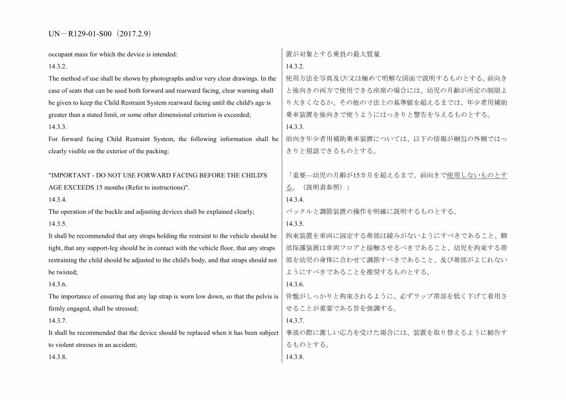
UN-R129-01-S00(2017.2.9) occupant mass for which the device is intended: 置が対象とする乗員の最大質量
14.3.2.
The method of use shall be shown by photographs and/or very clear drawings. In the
case of seats that can be used both forward and rearward facing, clear warning shall
be given to keep the Child Restraint System rearward facing until the child's age is
greater than a stated limit, or some other dimensional criterion is exceeded;
14.3.2.
使用方法を写真及び/又は極めて明解な図面で説明するものとする。前向き
と後向きの両方で使用できる座席の場合には、幼児の月齢が所定の制限よ
り大きくなるか、その他の寸法上の基準値を超えるまでは、年少者用補助
乗車装置を後向きで使うようにはっきりと警告を与えるものとする。
14.3.3.
For forward facing Child Restraint System, the following information shall be
clearly visible on the exterior of the packing:
"IMPORTANT - DO NOT USE FORWARD FACING BEFORE THE CHILD'S
AGE EXCEEDS 15 months (Refer to instructions)".
14.3.3.
前向き年少者用補助乗車装置については、以下の情報が梱包の外側ではっ
きりと視認できるものとする。
「重要—幼児の月齢が15カ月を超えるまで、前向きで使用しないものとす
る。(説明書参照)」
14.3.4.
The operation of the buckle and adjusting devices shall be explained clearly;
14.3.4.
バックルと調節装置の操作を明確に説明するものとする。
14.3.5.
It shall be recommended that any straps holding the restraint to the vehicle should be
tight, that any support-leg should be in contact with the vehicle floor, that any straps
restraining the child should be adjusted to the child's body, and that straps should not
be twisted;
14.3.5.
拘束装置を車両に固定する帯部は緩みがないようにすべきであること、脚
部保護装置は車両フロアと接触させるべきであること、幼児を拘束する帯
部を幼児の身体に合わせて調節すべきであること、及び帯部がよじれない
ようにすべきであることを推奨するものとする。
14.3.6.
The importance of ensuring that any lap strap is worn low down, so that the pelvis is
firmly engaged, shall be stressed;
14.3.6.
骨盤がしっかりと拘束されるように、必ずラップ帯部を低く下げて着用さ
せることが重要である旨を強調する。
14.3.7.
It shall be recommended that the device should be replaced when it has been subject
to violent stresses in an accident;
14.3.7.
事故の際に激しい応力を受けた場合には、装置を取り替えるように勧告す
るものとする。
14.3.8. 14.3.8.

UN-R129-01-S00(2017.2.9) Instructions for cleaning shall be given; 手入れの方法を記載するものとする。
14.3.9.
A general warning shall be given to the user concerning the danger of making any
alterations or additions to the device without the approval of the Type
Approval Authority, and a danger of not following closely the installation
instructions provided by the child restraint manufacturer;
14.3.9.
本装置に行政官庁の承認なしに何らかの変更又は追加することの危険性、
及び当該年少者用補助乗車装置のメーカーが指定した取り付け方法を確
実に守らなかった場合の危険性について、使用者に一般的な警告を与える
ものとする。
14.3.10.
When the chair is not provided with a textile cover, it shall be recommended that the
chair should be kept away from sunlight, otherwise it may be too hot for the child's
skin;
14.3.10.
椅子に布製カバーが付いていない場合には、椅子に直射日光が当たらない
ようにするものとする。そうしなければ、幼児の皮膚には高温になりすぎ
る恐れがあることを注意しなければならない。
14.3.11.
It shall be recommended that children are not left in their Child Restraint System
unattended;
14.3.11.
年少者用補助乗車装置に幼児を乗せたまま、置き去りにしないように勧告
するものとする。
14.3.12.
It shall be recommended that any luggage or other objects liable to cause injuries in
the event of a collision shall be properly secured.
14.3.12.
衝突の際に傷害の原因になる恐れのある荷物やその他の物体は、適切に固
定するように勧告するものとする。
14.3.13.
It shall be recommended that:
14.3.13.
下記について勧告するものとする。
14.3.13.1.
The Child Restraint System shall not be used without the cover;
14.3.13.1.
年少者用補助乗車装置はカバー無しで使用しないものとする。
14.3.13.2.
The Child Restraint System cover should not be replaced with any other than the one
recommended by the manufacturer, because the cover constitutes an integral part of
the restraint performance.
14.3.13.2.
年少者用補助乗車装置カバーは、拘束性能に不可欠な要素を構成している
ので、メーカーが推奨するもの以外と取り替えるべきでないものとする。
14.3.14.
There shall be provisions made so that the instructions can be retained on the child
14.3.14.
使用説明が年少者用補助乗車装置の全耐用期間にわたって、当該拘束装置

UN-R129-01-S00(2017.2.9) restraint for its life period or in the vehicle handbook in the case of built-in restraints. 上に保持できるように、又はビルトイン拘束装置の場合は、車両ハンドブ
ック内に保持できるように対策をとるものとする。
14.3.15.
For an "i-Size Child Restraint System", the user shall also be referred to the vehicle
manufacturer's handbook.
14.3.15.
「アイサイズ年少者用補助乗車装置」については、ユーザーは、車両メー
カーのハンドブックも参照するようにするものとする。
15. Names and addresses of Technical Services responsible for conducting
approval tests and of Type Approval Authorities
The Parties to the 1958 Agreement applying this Regulation shall communicate to
the United Nations Secretariat the names and addresses of the Technical Services
responsible for conducting approval tests and of the Type Approval Authorities
which grant approval and to which forms certifying approval or extension or refusal
or withdrawal of approval, or production definitively discontinued, issued in other
countries, are to be sent.
15. 認可試験の実施を担当する技術機関ならびに行政官庁の名称と所在地
本規則を適用する1958年協定締約国は、認可試験の実施を担当する技術機
関の名称と所在地、ならびに認可を付与し、また、他の国々において発行
される認可又は認可の拡大もしくは
拒否もしくは取消、又は生産中止の証明書の送付先になる行政官庁の名称
と所在地を国連事務局に通知するものとする。
16. Transitional provisions
16.1. As from the official date of entry into force of the 01 series
of amendments, no Contracting Party applying this Regulation shall
refuse to grant ECE approval under this Regulation as amended by the
01 series of amendments.
16.2. As from 1 September 2018, Contracting Parties applying
this Regulation shall grant approvals only if the Enhanced Child
Restraint System type to be approved meets the requirements of this
Regulation as amended by the 01 series of amendments.
16.3. Until 1 September 2018, Contracting Parties applying this
Regulation can continue to grant type approvals to Enhanced Child
16. 過渡規定
16.1. 01改訂シリーズの正式発効日以降、本規則を適用する締約国は、
01改訂シリーズにより改訂された本規則に基づくECE認可の付与を拒否し
ないものとする。
16.2. 2018年9月1日以降、本規則を適用する締約国は、認可対象の改良
型幼児拘束装置の型式が01改訂シリーズにより改訂された本規則の要件
を満たす場合に限り、認可を付与するものとする。
16.3. 2018年9月1日までは、本規則を適用する締約国は、引き続き、本
規則の初版の要件に適合する改良型幼児拘束装置に対し型式認可を付与
することができる。
16.4. 2020年9月1日までは、本規則を適用する締約国は、本規則の初版
に基づく認可拡大の付与を拒否しないものとする。

UN-R129-01-S00(2017.2.9) Restraint Systems which comply with the requirements of this
Regulation as in its original version.
16.4. Until 1 September 2020, Contracting Parties applying this Regulation
shall not refuse to grant extensions of approval to the original version of this
Regulation.
Annex 1
Communication
(Maximum format: A4 (210 x 297 mm)
issued by: Name of administration:
1 Distinguishing number of the country which has
granted/extended/refused/withdrawn approval (see approval provisions in the
Regulation).
concerning:2 2 Strike out what does not apply.
Approval granted
Approval extended
Approval refused
Approval withdrawn
Production definitively discontinued
of restraining devices for child occupants of power-driven vehicles, pursuant to
附則1
通知
(最大A4版(210×297 mm))
発行:行政官庁名
1 認可を付与/拡大/拒否/取消した国の識別番号(本規則の認可規定を参
照)。
協定規則第129号に基づく、動力駆動車両の幼児乗員用拘束装置の
認可付与
認可拡大
認可拒否
認可取消
生産中止
について2 2 該当しない項目を抹消する。
認可番号
UN-R129-01-S00(2017.2.9) Regulation No. 129.
Approval No.:
Extension No.:
拡大番号
1.1.
Forward-facing child restraint/rearward-facing child restraint/lateral-facing child
restraint
1.1.
前向き年少者用補助乗車装置/後向き年少者用補助乗車装置/横向き年少者
用補助乗車装置
1.2.
Integral/Non integral;2 2 Strike out what does not apply.
1.2.
一体型/非一体型2 2 該当しない項目を抹消する。
1.3.
Belt type: 2
(Adult) three-point belt
(Adult) lap belt
Special type belt/retractor 2 2 Strike out what does not apply.
1.3.
ベルトタイプ:2
(成人用)3点式ベルト
(成人用)腰ベルト
特殊型ベルト/巻取装置2 2 該当しない項目を抹消する。
1.4.
Other features: chair assembly/impact shield2 2 Strike out what does not apply.
1.4.
その他の特徴:チェアアッセンブリ/インパクトシールド2 2 該当しない項目を抹消する。
2.
Trade name or mark
2.
商品名又は商標
3.
Manufacturer's designation of the Child Restraint System
3.
メーカーによる年少者用補助乗車装置の名称
4.
Manufacturer's name
4.
メーカーの名称
5.
If applicable, name of his representative
5.
該当する場合は、その代理人の名称

UN-R129-01-S00(2017.2.9) 6.
Address
6.
所在地
7.
Submitted for approval on
7.
認可用提出日
8.
Technical Service conducting approval tests
8.
認可試験を実施する技術機関
9.
Type of device: deceleration/acceleration2 2 Strike out what does not apply.
9.
装置の種類:減速/加速2 2 該当しない項目を抹消する。
10.
Date of test report issued by that Service
10.
同技術機関発行の試験成績書の日付
11.
Number of test report issued by that Service
11.
同技術機関発行の試験成績書の番号
12.
Approval granted/extended/refused/withdrawn2 for size range x to x for i-Size
specific vehicle or for use as a "special needs restraint", position in vehicle 2 Strike out what does not apply.
12.
サイズ範囲xからxまでのアイサイズ特定車両又は「特殊ニーズ拘束装置」
として使用するための認可の付与/拡大/拒否/取消2、車両内での位置 2 該当しない項目を抹消する。
13.
Position and nature of the marking
13.
表示の位置と性質
14.
Place
14.
場所
15.
Date
15.
日付
16.
Signature
16.
署名
17. 17.

UN-R129-01-S00(2017.2.9) The following documents, bearing the approval number shown above, are attached to
this communication:
(a) Drawings, diagrams and plans of the child restraint, including any retractor, chair
assembly, impact shield fitted;
(b) Drawings, diagrams and plans of the vehicle structure and the seat structure, as
well as of the adjustment system and the attachments, including any energy absorber
fitted;
(c) Photographs of the child restraint and/or vehicle structure and seat structure;
(d) Instructions for fitting and use;
(e) List of vehicle models for which the restraint is intended.
上記認可番号を有する下記の書類をこの通知書に添付する。
(a) 年少者用補助乗車装置の図面、略図及び見取り図、装備した巻取装置、
チェアアッセンブリ、インパクトシールドを含む。
(b) 車両構造及び座席構造ならびに調節機構及び取り付け具の図面、略図
及び見取り図。装備したエネルギー吸収装置を含む。
(c) 年少者用補助乗車装置及び/又は車両構造及び座席構造の写真。
(d) 取り付け方法と使用方法の説明書。
(e) 当該拘束装置を使用する車両モデルのリスト。
Annex 2
Arrangements of the approval mark
附則2
認可マークの配置
The Enhanced Child Restraint System bearing the above approval mark is a device
capable of being fitted in any i-size compatible vehicle seating position and of being
used for the 40 cm - 70 cm size range and mass limit of 24 kg; it is approved in
France (E 2) under the number 012439. The approval number indicates that the
approval was granted in accordance with the requirements of the Regulation
concerning the approval of Enhanced Child Restraint Systems used onboard of motor
vehicles as amended by the 01 series of amendments. In addition the name of the
上記の認可マークをつけた改良型年少者用補助乗車装置は、いずれのアイ
サイズ適合車両着席位置にも取り付けることができ、40 cmから70 cmのサ
イズ範囲で24 kgの質量限界に対して使用できる装置である。当該装置は番
号012439によりフランス(E2)で認可されている。この認可番号は、01改
訂シリーズにより改訂された、自動車に搭載して使用される改良型年少者
用補助乗車装置の認可に関する規則の要件に従って、認可が付与されたこ
とを示す。さらに、認可マークに当該認可が付与される基準となった規則
a=最小 8 mm
UN 規則 No. 129/01
アイサイズ汎用 ISOFIX
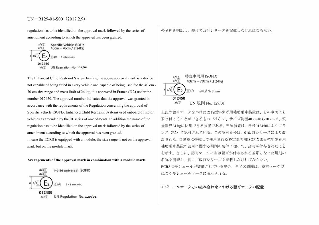
UN-R129-01-S00(2017.2.9) regulation has to be identified on the approval mark followed by the series of
amendment according to which the approval has been granted.
The Enhanced Child Restraint System bearing the above approval mark is a device
not capable of being fitted in every vehicle and capable of being used for the 40 cm -
70 cm size range and mass limit of 24 kg; it is approved in France (E 2) under the
number 012450. The approval number indicates that the approval was granted in
accordance with the requirements of the Regulation concerning the approval of
Specific vehicle ISOFIX Enhanced Child Restraint Systems used onboard of motor
vehicles as amended by the 01 series of amendments. In addition the name of the
regulation has to be identified on the approval mark followed by the series of
amendment according to which the approval has been granted.
In case the ECRS is equipped with a module, the size range is not on the approval
mark but on the module mark.
Arrangements of the approval mark in combination with a module mark.
の名称を明記し、続けて改訂シリーズを記載しなければならない。
上記の認可マークをつけた改良型年少者用補助乗車装置は、どの車両にも
取り付けることができるものではなく、サイズ範囲40 cmから70 cmで、質
量限界24 kgに使用できる装置である。当該装置は、番号012450によりフラ
ンス(E2)で認可されている。この認可番号は、01改訂シリーズにより改
訂された、自動車に搭載して使用される特定車両用ISOFIX改良型年少者用
補助乗車装置の認可に関する規則の要件に従って、認可が付与されたこと
を示す。さらに、認可マークに当該認可が付与される基準となった規則の
名称を明記し、続けて改訂シリーズを記載しなければならない。
ECRSにモジュールが装備されている場合、サイズ範囲は、認可マークで
はなくモジュールマークに表示される。
モジュールマークとの組み合わせにおける認可マークの配置
a=最小 8 mm
UN 規則 No. 129/01
特定車両用 ISOFIX

UN-R129-01-S00(2017.2.9) The Enhanced Child Restraint System bearing the above approval mark is a device,
including module(s), capable of being fitted in any i-size compatible vehicle seating
position. It is approved in France (E 2) under the number 012439. The approval
number indicates that the approval was granted in accordance with the requirements
of the Regulation concerning the approval of Enhanced Child Restraint Systems used
on board of motor vehicles as amended by the 01 series of amendments. In addition
the name of the regulation has to be identified on the approval mark followed by the
series of amendment according to which the approval has been granted.
The Enhanced Child Restraint System bearing the above approval mark is a device,
including module(s), not capable of being fitted in every vehicle. It is approved in
France (E 2) under the number 012450. The approval number indicates that the
approval was granted in accordance with the requirements of the Regulation
concerning the approval of Specific vehicle ISOFIX Enhanced Child Restraint
Systems used onboard of motor vehicles as amended by the 01 series of
amendments. In addition the name of the regulation has to be identified on the
approval mark followed by the series of amendment according to which the approval
has been granted.
Example of arrangements of the module mark in combination with an approval
mark
上記の認可マークをつけた改良型年少者用補助乗車装置は、いずれのアイ
サイズ適合車両着席位置にも取り付けることができ、モジュールを含む装
置である。当該装置は番号012439によりフランス(E2)で認可されている。
この認可番号は、01改訂シリーズにより改訂された、自動車に搭載して使
用される改良型年少者用補助乗車装置の認可に関する規則の要件に従っ
て、認可が付与されたことを示す。さらに、認可マークに当該認可が付与
される基準となった規則の名称を明記し、続けて改訂シリーズを記載しな
ければならない。
上記の認可マークをつけた改良型年少者用補助乗車装置は、どの車両にも
取り付けることができるものではない、モジュールを含む装置である。当
該装置は、番号012450によりフランス(E2)で認可されている。この認可
番号は、01改訂シリーズにより改訂された、自動車に搭載して使用される
特定車両用ISOFIX改良型年少者用補助乗車装置の認可に関する規則の要
件に従って、認可が付与されたことを示す。さらに、認可マークに当該認
可が付与される基準となった規則の名称を明記し、続けて改訂シリーズを
a=最小 8 mm
UN 規則 No. 129/01
アイサイズ汎用 ISOFIX
a=最小 8 mm
UN 規則 No. 129/01
特定車両用 ISOFIX
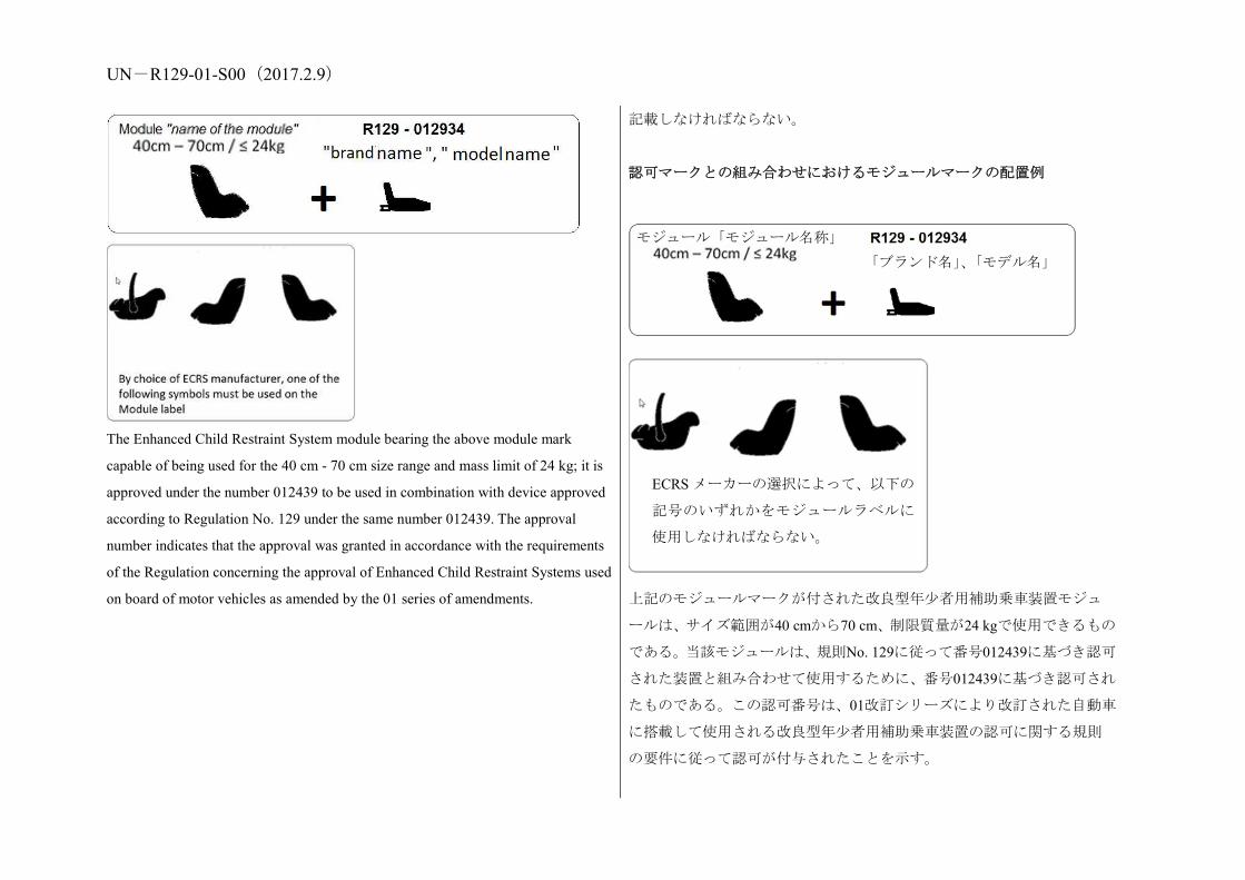
UN-R129-01-S00(2017.2.9)
The Enhanced Child Restraint System module bearing the above module mark
capable of being used for the 40 cm - 70 cm size range and mass limit of 24 kg; it is
approved under the number 012439 to be used in combination with device approved
according to Regulation No. 129 under the same number 012439. The approval
number indicates that the approval was granted in accordance with the requirements
of the Regulation concerning the approval of Enhanced Child Restraint Systems used
on board of motor vehicles as amended by the 01 series of amendments.
記載しなければならない。
認可マークとの組み合わせにおけるモジュールマークの配置例
上記のモジュールマークが付された改良型年少者用補助乗車装置モジュ
ールは、サイズ範囲が40 cmから70 cm、制限質量が24 kgで使用できるもの
である。当該モジュールは、規則No. 129に従って番号012439に基づき認可
された装置と組み合わせて使用するために、番号012439に基づき認可され
たものである。この認可番号は、01改訂シリーズにより改訂された自動車
に搭載して使用される改良型年少者用補助乗車装置の認可に関する規則
の要件に従って認可が付与されたことを示す。
「ブランド名」、「モデル名」
モジュール「モジュール名称」
ECRS メーカーの選択によって、以下の
記号のいずれかをモジュールラベルに
使用しなければならない。

UN-R129-01-S00(2017.2.9)
Annex 3
Arrangement of apparatus for dust resistance test
附則3
耐粉塵試験用装置の配置
Annex 4
Corrosion test
附則4
腐食試験
1. Test apparatus 1. 試験装置
1.1.
The apparatus shall consist of a mist chamber, a salt solution reservoir, a supply of
suitably conditioned compressed air, one or more atomizing nozzles, sample
supports, provision for heating the chamber, and necessary means of control. The
size and detailed construction of the apparatus shall be optional, provided that the
1.1.
装置は、霧チャンバー、食塩水槽、適切に処理された圧縮空気を供給する
装置、1個以上の噴霧ノズル、サンプル支持台、チャンバー加熱用装置、
及び必要な操作装置で構成するものとする。装置のサイズと詳細構造は、
試験条件が満足されるかぎり、任意選択とする。

UN-R129-01-S00(2017.2.9) test conditions are met.
1.2.
It is important to ensure that drops of solution accumulated on the ceiling or cover of
the chamber do not fall on test samples.
1.2.
チャンバーの天井又はカバーに蓄積した溶液が試験片上に滴下しないよ
うにすることが重要である。
1.3.
Drops of solution which fall from test samples shall not be returned to the reservoir
for respraying.
1.3.
試験片から落下する溶液の滴下は、再噴霧のために食塩水槽に戻さないも
のとする。
1.4.
The apparatus shall not be constructed of materials that will affect the corrosiveness
of the mist.
1.4.
装置は、霧の腐食性に影響する材料で構成しないものとする。
2. Location of test samples in the mist cabinet 2. 噴霧キャビネット内の試験片の位置
2.1.
Samples, except retractors, shall be supported or suspended between 15 deg. and 30
deg. from the vertical and preferably parallel to the principal direction of horizontal
flow of mist through the chamber, based upon the dominant surface being tested.
2.1.
供試品は、巻取装置を除き、試験対象の主要表面に基づき、垂直線から 15°
と 30°の間で、チャンバー内を水平に流れる霧の主方向になるべく平行に
支持又は懸吊するものとする。
2.2.
Retractors shall be supported or suspended so that the axes of the reel for storing the
strap shall be perpendicular to the principal direction of horizontal flow of mist
through the chamber. The strap opening in the retractor shall also be facing in this
principal direction.
2.2.
巻取装置は帯部を格納するリールの軸がチャンバー内を水平に流れる霧
の主方向に垂直になるように、支持又は懸吊するものとする。巻取装置の
帯部出口も霧の主方向に向けるものとする。
2.3.
Each sample shall be so placed as to permit free settling of mist on all samples.
2.3.
各供試品は、全供試品の上に霧が自由沈降するように置くものとする。
2.4.
Each sample shall be so placed as to prevent salt solution from one sample dripping
on to any other sample.
2.4.
各供試品は 1 つの供試品から落ちる食塩水が他の供試品に滴下しないよう
に置くものとする。
3. Salt solution 3. 食塩水

UN-R129-01-S00(2017.2.9) 3.1.
The salt solution shall be prepared by dissolving 5 +/- 1 parts by mass of sodium
chloride in 95 parts of distilled water. The salt shall be sodium chloride substantially
free of nickel and copper and containing not more than 0.1 per cent of sodium iodide
and not more than 0.3 per cent of total impurities in the dry state.
3.1.
食塩水は蒸留水95部に塩化ナトリウムを5±1の質量部で溶解して調整する
ものとする。食塩はニッケル及び銅をほとんど含まず、乾燥状態での含有
量がヨウ化ナトリウム0.1%以下、全不純物量0.3%以下の塩化ナトリウムと
する。
3.2.
The solution shall be such that, when atomized at 35 deg. C, the collected solution is
in the pH range of 6.5 to 7.2.
3.2.
溶液は、35℃で霧化されたとき、収集した溶液の pH が 6.5 から 7.2 の範囲
内にあるものとする。
4. Compressed air 4. 圧縮空気
4.1.
The compressed air supply to the nozzle or nozzles for atomizing the salt solution
shall be free of oil and dirt, and maintained at a pressure between 70 kN/m2 and 170
kN/m2.
4.1.
食塩水を霧化するため 1 個又は複数のノズルに供給される圧縮空気は、油
分及び塵埃が無く、70 kN/m2 から 170 kN/m2 までの圧力に保たれるものと
する。
5. Conditions in the mist chamber 5. 霧チャンバー内の条件
5.1.
The exposure zone of the mist chamber shall be maintained at 35 deg. C +/- 5 deg. C.
At least two clean mist collectors shall be placed within the exposure zone, so that no
drops of solution from the test samples or any other sources are collected. The
collectors shall be placed near the test samples, one as near as possible to any nozzle
and one as far as possible from all nozzles. The mist shall be such that, for each 80
cm2 of horizontal collecting area, from 1.0 to 2.0 ml
of solution per hour, when measured over an average of at least 16 hours, is collected
in each collector.
5.1.
霧チャンバーの暴露ゾーンは、35℃±5℃に維持するものとする。少なくと
も2つの清浄な集霧器を暴露ゾーンに置き、試験片又はその他の発生源か
らの溶液の滴下が収集されることがないようにするものとする。集霧器は
試験サンプルの付近に置き、1つは任意のノズルにできるだけ近くに、も
う1つはあらゆるノズルから極力遠くに置くものとする。霧は、少なくと
も16時間の平均で測定した場合、各80 cm2の水平収集面積当たり毎時1.0か
ら2.0 mlの溶液が各集霧器内に収集されるものとする。
5.2.
The nozzle or nozzles shall be directed or baffled, so that the spray does not impinge
directly on the test samples.
5.2.
1 つ又は複数のノズルは、噴霧が試験サンプルに直接当たらないように方
向を逸らすか又は遮るものとする。

UN-R129-01-S00(2017.2.9)
Annex 5
Abrasion and microslip test
附則5
摩耗及びマイクロスリップ試験
Figure 1: Procedure type 1
Figure 2: Procedure type 2
図1:手順タイプ1
図 2:手順タイプ 2
内側バー用
保護帯部

UN-R129-01-S00(2017.2.9)
Figure 3: Microslip Test
Total travel: 300 +/- 20 mm
図 3:マイクロスリップ試験
総移動量:300±20 mm
水平面内の帯部
バックルによる試験
ガイドまたはブーリーによる試験
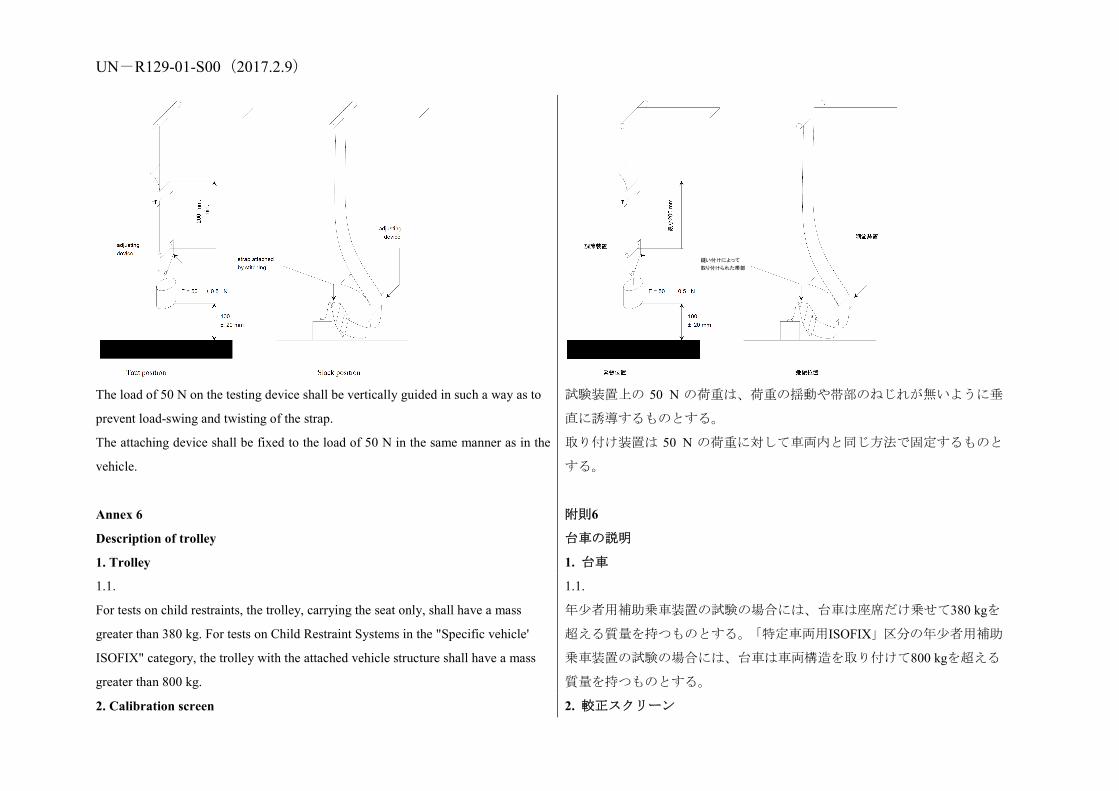
UN-R129-01-S00(2017.2.9)
The load of 50 N on the testing device shall be vertically guided in such a way as to
prevent load-swing and twisting of the strap.
The attaching device shall be fixed to the load of 50 N in the same manner as in the
vehicle.
試験装置上の 50 N の荷重は、荷重の揺動や帯部のねじれが無いように垂
直に誘導するものとする。
取り付け装置は 50 N の荷重に対して車両内と同じ方法で固定するものと
する。
Annex 6
Description of trolley
附則6
台車の説明
1. Trolley 1. 台車
1.1.
For tests on child restraints, the trolley, carrying the seat only, shall have a mass
greater than 380 kg. For tests on Child Restraint Systems in the "Specific vehicle'
ISOFIX" category, the trolley with the attached vehicle structure shall have a mass
greater than 800 kg.
1.1.
年少者用補助乗車装置の試験の場合には、台車は座席だけ乗せて380 kgを
超える質量を持つものとする。「特定車両用ISOFIX」区分の年少者用補助
乗車装置の試験の場合には、台車は車両構造を取り付けて800 kgを超える
質量を持つものとする。
2. Calibration screen 2. 較正スクリーン
縫い付けによって
取り付けられた帯部

UN-R129-01-S00(2017.2.9) 2.1.
A calibration screen shall be attached firmly to the trolley with a movement limit line
plainly marked on it to enable compliance with forward movement criteria to be
determined from photographic records.
2.1.
較正スクリーンは、前方移動基準に適合していることが写真記録から測定
できるように、移動限界線をはっきりとマークして台車にしっかりと取り
付けるものとする。
3. Test bench 3. 試験台
3.1.
The test bench shall be constructed as follows:
3.1.
試験台は以下のように構成するものとする。
3.1.1.
A rigid back, fixed, dimensions of which are given in Appendix 1 to this annex;
3.1.1.
固定の剛性背もたれ部。その寸法は本附則の付録1に記載されている。
3.1.2.
Rigid seating, made from a rigid metal sheet, dimensions of which are given in
Appendix 1 to this annex.
3.1.2.
剛性の板金で作られた剛性の着席部。その寸法は本附則の付録1に記載さ
れている。
3.1.3.
For access to the ISOFIX anchorage system, openings shall be made at the rear of
the test bench seat cushion, as prescribed in Appendix 1 to this annex;
3.1.3.
ISOFIX 取付装置に手が届くように、本附則の付録 1 で規定されているよ
うに、試験台シートクッションの後部に、開口部を作るものとする。
3.1.4.
The width of the test bench shall be 800 mm;
3.1.4.
試験台の幅は 800 mm とする。
3.1.5.
The back and the seating shall be covered with polyurethane foam, the characteristics
of which are given in Table 1. The dimensions of the cushion are given in Appendix
1 to this annex;
Table 1
Standard Value Unit
Density EN ISO 845 68-74 Kg/m3
Compression resistance EN ISO 3386/1 (40 % compression) 13 kPa
3.1.5.
背もたれ部及び着席部は、表1にある特性を持ったポリウレタンフォーム
で被覆するものとする。クッションの寸法は本附則の付録1に記載されて
いる。
表 1
標準 値 単位
密度 EN ISO 845 68-74 Kg/m3

UN-R129-01-S00(2017.2.9) Indentation Load Deflection (ILD)
EN ISO 2439B (40 % compression) 480 (+/15%) N
Tensile strenght EN ISO 1798 > 150 kPa
Ultimate elongation EN ISO 1798 > 120 %
Compression set EN ISO 1856 (22hr/50 %/70 deg. C) < 3 %
圧縮抵抗 EN ISO 3386/1(40%圧縮) 13 kPa
押込み荷重たわみ(ILD) EN ISO 2439B(40%圧縮) 480(+/15%) N
張力強度 EN ISO 1798 ≧150 kPa
極限伸び EN ISO 1798 ≧120 %
圧縮永久ひずみ EN ISO 1856(22時間/50%/70℃) ≦3 %
3.1.6.
The polyurethane foam shall be covered with a sun shade cloth, made of
poly-acrylate fibre, the characteristics of which are given in Table 2.
Table 2
Specific mass (g/m2) 290
Breaking strength according to DIN 53587 on test specimen 50 mm wide:
Lengthwise (kg): 120
Breadth wise (kg): 80
3.1.6.
ポリウレタンフォームは、表2に示す特性を持ったポリアクリル酸繊維製
の日除け布で被覆するものとする。
表 2
比質量(g/m2) 290
幅50 mmの試験片に対するDIN 53587による破壊強度:
縦方向(kg): 120
横方向(kg): 80
3.1.7.
Covering the test bench seat cushion and the test bench seat back cushion
3.1.7.
試験台シートクッションと試験台座席背もたれクッションの被覆
3.1.7.1.
The test bench seat cushion is produced out of a square foam block (800 x 575 x 135
mm) in such a way (see Figure 1 of Appendix 1 to this annex) that its shape
resembles the shape of the aluminium bottom-plate specified in Figure 2 of
Appendix 1 to this annex.
3.1.7.1.
試験台シートクッションは、長方形のフォームブロック(800×575×135 mm)
から成形し(本附則の付録1の図1参照)、その形状が本附則の付録1の図2
で指定されているアルミニウム製の底板の形状に似ているようにする。
3.1.7.2.
Six holes are drilled in the bottom-plate in order to fasten it to the trolley with bolts.
3.1.7.2.
底板にドリルで6つの穴を開けて、台車にボルトで固定できるようにする。
UN-R129-01-S00(2017.2.9) The holes are drilled alongside the longest side of the plate, three on each side, their
position being dependent on the construction of the trolley. Six bolts are put through
the holes. It is recommended to glue the bolts on the plate with an appropriate
adhesive. Afterwards, the bolts are fastened with nuts.
穴は各側に3個ずつ板の最も長い片に沿って開け、その位置は台車の構造
に依存する。6本のボルトを穴に通す。ボルトは適切な接着剤で板に接着
することを推奨する。その後、ボルトをナットで締める。
3.1.7.3.
The cover material (1,250 x 1,200 mm, see Figure 3 of Appendix 1 to this annex) is
cut across the width in such a way that it is not possible for the material to overlap
after covering. There should be a gap of about 100 mm between the edges of the
cover material. Therefore the material has to be cut at about 1,200 mm.
3.1.7.3.
被覆材(1,250×1,200 mm、本附則の付録1の図3参照)は、被覆後に材料が
重なることがないような幅で切断する。被覆材の端どうしの間には約100
mmの隙間を空けるべきものとする。したがって、材料は約1,200 mmで切
断する必要がある。
3.1.7.4.
The cover material is marked with two lines which run across the width. They are
drawn 375 mm from the centreline of the cover material (see Figure 3 of Appendix 1
to this annex).
3.1.7.4.
被覆材の幅に沿って 2 本の線をマークする。これらの線は、被覆材の中心
線から 375 mm のところに引く(本附則の付録 1 の図 3 参照)。
3.1.7.5.
The test bench seat cushion is placed upside down on the cover material with the
aluminium bottom-plate on top.
3.1.7.5.
試験台シートクッションは、被覆材の上に逆さまにして置き、アルミニウ
ム製の底板を一番上に置く。
3.1.7.6.
On both sides the cover material is stretched until the lines drawn on it match the
edges of the aluminium bottom-plate. At each bolt position, small incisions are made
and the cover material is pulled over the bolts.
3.1.7.6.
被覆材を両側に伸ばし、その上に書かれた線をアルミニウム製底板の両端
に合わせる。それぞれのボルトの位置で、小さな切り込みを入れ、ボルト
を覆うように被覆材を引っ張る。
3.1.7.7.
At the position of the grooves in the bottom-plate and in the foam, the cover material
should be incised.
3.1.7.7.
底板及びフォームの溝の位置に合わせて、被覆材に切り込みを入れるべき
ものとする。
3.1.7.8.
The cover is glued to the aluminium plate with flexible glue. The nuts have to be
removed before gluing.
3.1.7.8.
被覆をフレキシブルグルーを使ってアルミニウム製の板に接着する。接着
する前にナットは取り外す必要がある。

UN-R129-01-S00(2017.2.9) 3.1.7.9.
The flaps on the side are folded onto the plate and are glued as well.
3.1.7.9.
側面のフラップは板上に折り畳み、同様に接着する。
3.1.7.10.
The flaps in the grooves are folded inside and taped with a strong tape.
3.1.7.10.
溝の中のフラップは内側に折り畳み、強力なテープを使ってテーピングす
る。
3.1.7.11.
The flexible glue has to dry for at least 12 hours.
3.1.7.11.
フレキシブルグルーは少なくとも 12 時間かけて乾燥させる必要がある。
3.1.7.12.
The test bench seat-back cushion is covered in exactly the same way as the test
bench seat cushion, only the lines on the cover material (1,250 x 850 mm) are drawn
333 mm apart from the centreline of the material.
3.1.7.12.
試験台座席・バッククッションは試験台シートクッションとまったく同一
の方法で被覆するが、被覆材(1,250×850 mm)上の線だけは、材料の中心
線から 333 mm 離れたところに引く。
3.1.8.
Line Cr is coincident with the intersection line between the top plane of the test
bench seat cushion and the front plane of the test bench seat-back cushion.
3.1.8.
線 Cr は、試験台シートクッションの上面と試験台座席・バッククッショ
ンの前面との交線と一致する。
3.2.
Test of rearward-facing devices
3.2.
後向き装置の試験
3.2.1.
A special frame shall be fitted on the trolley in order to support the child restraint
system as shown in Figure 1.
3.2.1.
図 1 に示すように、年少者用補助乗車装置を支えるために台車に特別な枠
を取り付けるものとする。
3.2.2.
A steel tube shall be attached firmly to the trolley in such a way that a load of 5,000
+/- 50 N applied horizontally to the centre of the tube does not cause a movement
greater than 2 mm.
3.2.2.
鋼管をしっかりと台車に取り付けるものとするが、その際、当該管の中心
に 5,000±50 N の荷重を水平に加えたとき 2 mm を超える移動が起きないよ
うに取り付ける。
3.2.3.
The dimensions of the tube shall be: 500 x 100 x 90 mm.
Figure 1: Arrangements for testing a rearward -facing device
3.2.3.
管の寸法は、500×100×90 mmとする。
図 1:後向き装置の試験の配置

UN-R129-01-S00(2017.2.9)
3.3.
Trolley floor pan
3.3.
台車フロアパン
3.3.1.
The floor pan of the trolley shall be constructed of a flat sheet of metal of uniform
thickness and material, see Figure 2 of Appendix 3 to this annex.
3.3.1.
台車のフロアパンは、厚さと材質が均一の平らな金属板で製作するものと
する。本附則の付録 3 の図 2 を参照。
3.3.1.1.
The floor pan shall be rigidly mounted on the trolley. The height of the floor pan
relative to the Cr axis projection point, dimension1 in Appendix 2 to this annex,
Figure 2, shall be adjusted to meet the requirements of paragraph 7.1.3.6.3. of this
Regulation. 1 The dimension shall be of 210 mm with an adjustment range of +/-70 mm.
3.3.1.1.
フロアパンを台車上に堅く取り付けるものとする。Cr軸投影点に対するフ
ロアパンの高さ(本附則の付録2の図2の寸法1)は、本規則の7.1.3.6.3項の
要件を満たすように調節するものとする。 1 寸法は、210 mm、調節範囲±70 mm とする。
3.3.1.2.
The floor pan shall be designed so that the surface hardness should not be below 120
HB, according to EN ISO 6506-1:1999.
3.3.1.2.
フロアパンは、表面の硬さが EN ISO 6506-1:1999 に基づき 120 HB 以上に
なるように設計するものとする。
3.3.1.3.
The floor pan shall withstand an applied vertical concentrated load of 5 kN without
causing a vertical movement greater than 2 mm referring to Cr axis and without any
permanent deformation occurring.
3.3.1.3.
フロアパンは、5 kN の垂直集中負荷を加えたときに、Cr 軸を基準にして 2
mm を超える垂直移動を引き起こさず、いかなる恒久的変形も生じずに、
その負荷に耐えるものとする。

UN-R129-01-S00(2017.2.9) 3.3.1.4.
The floor pan shall have a surface roughness not exceeding Ra 6,3 according to ISO
4287:1997.
3.3.1.4.
フロアパンの表面の粗さは、ISO 4287:1997 に基づき Ra 6.3 を超えないも
のとする。
3.3.1.5.
The floor pan shall be designed so that no permanent deformation is occurring after a
dynamic test of a Child Restraint System, according to this Regulation.
3.3.1.5.
フロアパンは本規則に基づく年少者用補助乗車装置の動的試験の後に恒
久的変形が生じないように設計するものとする。
4. Stopping device 4. 停止装置
4.1.
The device consists of two identical absorbers mounted in parallel.
4.1.
本装置は並列に取り付けられた 2 つの同じ緩衝器からなる。
4.2.
If necessary, an additional absorber shall be used for each 200 kg increase in nominal
mass. Each absorber shall comprise:
4.2.
必要ならば、公称質量が 200 kg 増加するごとに緩衝器を追加して使用する
ものとする。各緩衝器は下記のもので構成されるものとする。
4.2.1.
An outer casing formed from a steel tube;
4.2.1.
鋼管製の外部ケーシング、
4.2.2.
A polyurethane energy-absorber tube;
4.2.2.
ポリウレタン製エネルギー吸収管、
4.2.3.
A polished-steel olive-shaped knob penetrating into the absorber; and
4.2.3.
緩衝器に貫入する研磨鋼のオリーブ形ノブ、及び
4.2.4.
A shaft and an impact plate.
4.2.4.
軸と衝撃板。
4.3.
The dimensions of the various parts of this absorber are shown in the diagram
reproduced in Appendix 2 to this annex.
4.3.
本緩衝器の種々の部品の寸法は、本附則の付録 2 の図に示す。
4.4.
The characteristics of the absorbing material are given in Table 3 and Table 4 of this
annex.
4.4.
吸収材の特性は、本附則の表 3 及び表 4 に示す。

UN-R129-01-S00(2017.2.9) 4.5.
The stopping device assembly shall be maintained for at least 12 hours at a
temperature between 15 deg. C and 25 deg. C before being used for the calibration
tests described in Annex 7 to this Regulation. The stopping device shall, for each
type of test, meet the performance requirements laid down in Annex 7, Appendices 1
and 2. For dynamic tests of a child restraint, the stopping device assembly shall be
maintained for at least 12 hours at the same temperature, to within +/-2 deg. C, as
that of the calibration test. Any other device giving equivalent results can be
accepted.
able 3: Characteristics of the absorbing material "A"2 2 The address to obtain the relevant ASTM standards is: ASTM, 1916 Race Street,
Philadelphia, USA PA 19 103.
(ASTM Method 2000 (1980) unless otherwise stated)
Shore hardness A: 88 +/- 2 at 20 deg. C +/- 5 deg. C temperature
Breaking strength: Ro> 300 kg/cm2 Minimum elongation: Ao> 400 per cent Module at 100 per cent elongation: > 70 kg/cm2 Module at 300 per cent elongation: > 130 kg/cm2
Low temperature brittleness (ASTM Method D 736): 5 hours at -55 deg. C
Compression set (Method B): 22 hours at 70 deg. C < 45 per cent
Density at 25 deg. C: 1.08 to 1.12
Ageing in air (ASTM Method D 573 (1981)):
4.5.
停止装置アセンブリは、本規則の附則7に説明されている較正試験に使用
する前に15℃から25℃の温度で少なくとも12時間保持するものとする。停
止装置は、各タイプの試験ごとに附則7の付録1及び2に定める性能要件を
満たすものとする。年少者用補助乗車装置の動的試験の場合には、停止装
置アセンブリは、較正試験の温度との差が±2℃以内の温度で少なくとも12
時間保持するものとする。同等の結果が得られる他の装置も認められる。
表3:吸収材「A」の特性2 2 関連する ASTM 規格の入手先: ASTM, 1916 Race Street, Philadelphia, USA
PA 19 103。
(別段の定めがない限りASTM法2000 (1980)による)
ショア硬度A: 温度20℃±5℃において88±2
破壊強度: Ro≧300 kg/cm2
最小伸び: Ao≧400 %
100%の伸びにおけるモジュール: ≧70 kg/cm2
300%の伸びにおけるモジュール: ≧130 kg/cm2
低温脆性(ASTM法D 736): -55℃で5時間
圧縮永久ひずみ(B法): 70℃で22時間≦45%
25℃における密度: 1.08から1.12
空気中での劣化(ASTM法D 573
(1981)):
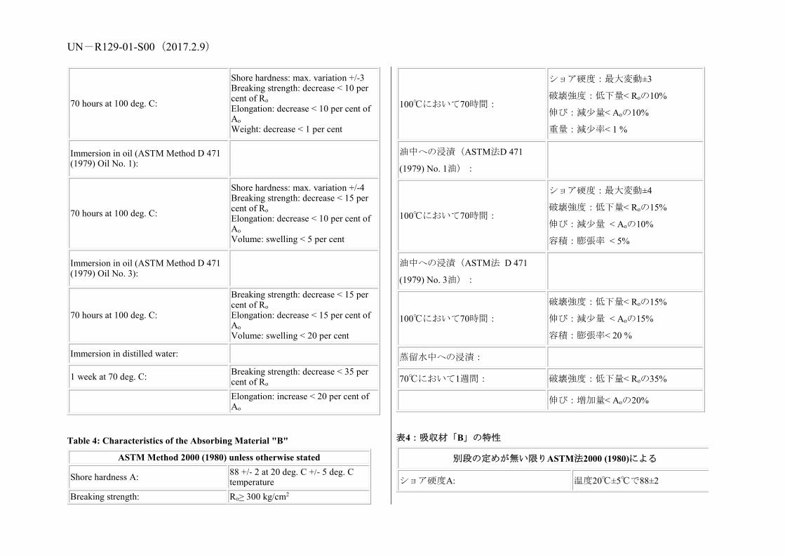
UN-R129-01-S00(2017.2.9)
70 hours at 100 deg. C:
Shore hardness: max. variation +/-3 Breaking strength: decrease < 10 per cent of Ro Elongation: decrease < 10 per cent of Ao Weight: decrease < 1 per cent
Immersion in oil (ASTM Method D 471 (1979) Oil No. 1):
70 hours at 100 deg. C:
Shore hardness: max. variation +/-4 Breaking strength: decrease < 15 per cent of Ro Elongation: decrease < 10 per cent of Ao Volume: swelling < 5 per cent
Immersion in oil (ASTM Method D 471 (1979) Oil No. 3):
70 hours at 100 deg. C:
Breaking strength: decrease < 15 per cent of Ro Elongation: decrease < 15 per cent of Ao Volume: swelling < 20 per cent
Immersion in distilled water:
1 week at 70 deg. C: Breaking strength: decrease < 35 per cent of Ro
Elongation: increase < 20 per cent of Ao
Table 4: Characteristics of the Absorbing Material "B"
ASTM Method 2000 (1980) unless otherwise stated
Shore hardness A: 88 +/- 2 at 20 deg. C +/- 5 deg. C temperature
Breaking strength: Ro> 300 kg/cm2
100℃において70時間:
ショア硬度:最大変動±3
破壊強度:低下量< Roの10%
伸び:減少量< Aoの10%
重量:減少率< 1 %
油中への浸漬(ASTM法D 471
(1979) No. 1油):
100℃において70時間:
ショア硬度:最大変動±4
破壊強度:低下量< Roの15%
伸び:減少量 < Aoの10%
容積:膨張率 < 5%
油中への浸漬(ASTM法 D 471
(1979) No. 3油):
100℃において70時間:
破壊強度:低下量< Roの15%
伸び:減少量 < Aoの15%
容積:膨張率< 20 %
蒸留水中への浸漬:
70℃において1週間: 破壊強度:低下量< Roの35%
伸び:増加量< Aoの20%
表4:吸収材「B」の特性
別段の定めが無い限りASTM法2000 (1980)による
ショア硬度A: 温度20℃±5℃で88±2

UN-R129-01-S00(2017.2.9) Minimum elongation: Ao> 400 per cent Module at 100 per cent elongation: > 70 kg/cm2 Module at 300 per cent elongation: > 130 kg/cm2 Low temperature brittleness (ASTM Method D 736): 5 hours at -55 deg. C
Compression set (Method B): 22 hours at 70 deg. C < 45 per cent Density at 25 deg. C: 1.08 to 1.12 Ageing in air (ASTM Method D 573 (1981)):
70 hours at 100 deg. C:
Shore hardness: max. variation +/-4 Breaking strength: decrease < 15 per cent of Ro Elongation: decrease < 10 per cent of Ao Volume: swelling < 5 per cent
Immersion in oil (ASTM Method D 471 (1979) Oil No. 3):
70 hours at 100 deg. C:
Breaking strength: decrease < 15 per cent of Ro Elongation: decrease < 15 per cent of Ao Volume: swelling < 20 per cent
Immersion in distilled water:
1 week at 70 deg. C Breaking strength: decrease < 35 per cent of Ro
Elongation: increase < 20 per cent of Ao
破壊強度: Ro≧300 kg/cm2
最小伸び: Ao≧400 %
100%の伸びにおいて: ≧70 kg/cm2
300%の伸びにおいて: ≧130 kg/cm2
低温脆性(ASTM法D 736): -55℃で5時間
圧縮永久ひずみ(B法): 70℃で22時間≦45%
25℃における密度: 1.08から1.12
空気中での劣化(ASTM法D 573 (1981)):
100℃において70時間:
ショア硬度:最大変動±4
破壊強度:低下量< Roの15%
伸び:減少量< Aoの10%
容積:膨張率< 5%
油中への浸漬(ASTM法D 471 (1979) No. 3
油):
100℃において70時間:
破壊強度:低下量< Roの15%
伸び:減少量< Aoの15%
容積:膨張率< 20%
蒸留水中への浸漬:
70℃において1週間 破断強度:低下量< Roの35%
伸び:増加量< Aoの20%

UN-R129-01-S00(2017.2.9) Annex 6 - Appendix 1
Figure 1: Dimensions of the seat cushions
附則6—付録1
図1:シート及びシートクッションの寸法 (単位:mm)

UN-R129-01-S00(2017.2.9)
Figure 2: Dimensions of the aluminium bottom-plate
図2:アルミニウム底板の寸法
Figure 3: Dimensions of the cover material(dimensions in mm) 図3:カバー材料の寸法(寸法単位はmm)
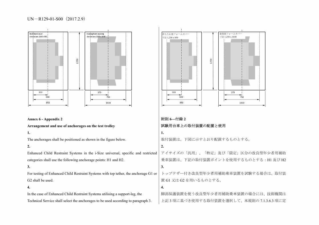
UN-R129-01-S00(2017.2.9)
Annex 6 - Appendix 2
Arrangement and use of anchorages on the test trolley
附則 6—付録 2
試験用台車上の取付装置の配置と使用
1.
The anchorages shall be positioned as shown in the figure below.
1.
取付装置は、下図に示すとおり配置するものとする。
2.
Enhanced Child Restraint Systems in the i-Size universal, specific and restricted
categories shall use the following anchorage points: H1 and H2.
2.
アイサイズの「汎用」、「特定」及び「限定」区分の改良型年少者用補助
乗車装置は、下記の取付装置ポイントを使用するものとする:H1 及び H2
3.
For testing of Enhanced Child Restraint Systems with top tether, the anchorage G1 or
G2 shall be used.
3.
トップテザー付き改良型年少者用補助乗車装置を試験する場合は、取付装
置 G1 又は G2 を用いるものとする。
4.
In the case of Enhanced Child Restraint Systems utilising a support-leg, the
Technical Service shall select the anchorages to be used according to paragraph 3.
4.
脚部保護装置を使う改良型年少者用補助乗車装置の場合には、技術機関は
上記 3 項に基づき使用する取付装置を選択して、本規則の 7.1.3.6.3 項に定
着座部フォームカバー 寸法 1,250 x 1030
背もたれ部フォームカバー 寸法 1,250 x 850

UN-R129-01-S00(2017.2.9) above and with the support-leg adjusted as specified in paragraph 7.1.3.6.3. of this
Regulation.
めるように脚部保護装置を調節するものとする。
5.
The structure carrying the anchorages shall be rigid. The upper anchorages shall not
be displaced by more than 0.2 mm in the longitudinal direction when a load of 980 N
is applied to them in that direction. The trolley shall be so constructed that no
permanent deformation shall occur in the parts bearing the anchorages during the
test..
Figure 1: Top View - Bench with ISOFIX anchorages (Tolerance general: +/-2)
Figure 2
Side View – Bench with anchorages (Tolerance general: ±2 mm)
5.
取付装置を保持する構造は剛性であるものとする。上部取付装置は980 N
の荷重を縦方向に当該取付装置に加えたとき、当該縦方向への移動が0.2
mmを超えないものとする。台車は、試験中に取付装置を保持する部位に
永久変形が生じないような構造であるものとする。
図1:平面図—ISOFIX取付装置付きベンチ(一般公差:±2)
図 2:側面図—アンカレッジ付きベンチ(一般公差:±2 mm)
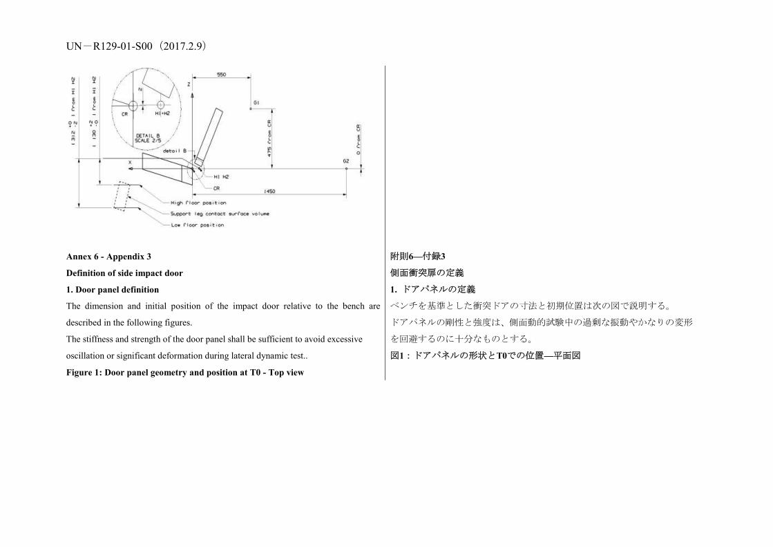
UN-R129-01-S00(2017.2.9)
Annex 6 - Appendix 3
Definition of side impact door
附則6—付録3
側面衝突扉の定義
1. Door panel definition
The dimension and initial position of the impact door relative to the bench are
described in the following figures.
The stiffness and strength of the door panel shall be sufficient to avoid excessive
oscillation or significant deformation during lateral dynamic test..
Figure 1: Door panel geometry and position at T0 - Top view
1. ドアパネルの定義
ベンチを基準とした衝突ドアの寸法と初期位置は次の図で説明する。
ドアパネルの剛性と強度は、側面動的試験中の過剰な振動やかなりの変形
を回避するのに十分なものとする。
図1:ドアパネルの形状とT0での位置—平面図

UN-R129-01-S00(2017.2.9)
Figure 2: Door panel geometry - Side view
Figure 3: Door panel approximate maximum intrusion - Side view (For
information)
図2:ドアパネルの形状—側面図
図 3:ドアパネルの最大食い込み量の近似値—側面図(参考)

UN-R129-01-S00(2017.2.9)
2. Panel padding specification 2. パネルパッディング仕様
2.1.
General
The impact surface of the door panel shall be entirely covered with a padding
material of 55 mm in thickness (see Figure 1 above). The material shall comply with
the performance criteria specified in paragraph 2.3. (Figure 4 below) of this appendix
when tested in accordance with paragraph 2.2. of this appendix.
A material combination meeting these requirements is described in paragraph 2.4. of
this appendix.
2.1.
一般要件
ドアパネルの衝突面は厚さ55 mmのパッディング材料で全体が覆われてい
るものとする。(上記図1を参照)、本規則の付録3の2.2項で説明されてい
るようにセットアップされた試験で実現される、本規則の付録3の2.3項(下
記図4)で説明されている性能基準に適合しなければならない。
これらの要件を満たす材料の組み合わせは本付録の2.4項に規定されてい
る。
2.2.
Test procedure for the assessment of panel padding material
The test set up consists of a simple drop test using a spherical head form. The
spherical head form has a diameter of 150 mm and a mass of 6 kg (±0.1 kg). The
impact speed is 4 m/s (±0.1 m/s). The instrumentation should allow the assessment
of the time of first contact between the impactor and the sample as well as the head
2.2.
パネルパッディング材料の評価用の試験手順
試験のセットアップは、球状ヘッドフォームを使った単純な落下試験で構
成される。球状ヘッドフォームは、直径150 mmで、質量6 kg(±0.1 kg)で
ある。衝突速度は4 m/s(±0.1 m/s)である。
計装は、衝撃装置と供試品の最初の接触時点と、少なくとも衝突方向(Z

UN-R129-01-S00(2017.2.9) form acceleration at least in direction of impact
(Z-direction).
The material sample should have the dimensions of 400 x 400 mm. The sample
should be impacted in its centre.
方向)のヘッドフォームの加速度の評価を可能とするべきものとする。
供試材料の寸法は 400×400 mm とすべきものとする。供試品は中央で衝突
すべきものとする。
2.3.
Performance criteria for the padding material
The time of first contact between sample material and head form (t0) is 0 ms.
The impactor acceleration shall not exceed 58 g.
Figure 4: Corridor for the padding material
Key
1 - Upper limit of 58 g
2 - Lower limit for the maximum peak at 53 g (11 to 12 ms)
3 - Upper limit for the decline of acceleration (15 g at 20,5 ms to 10 g at 21,5 ms)
4 - Lower limit for the decline of acceleration (10 g at 20 ms to 7 g at 21 ms)
2.3.
パッディング材料の性能基準
供試材料とヘッドフォームの最初の接触の時点(t0)は0 msである。
衝撃装置の加速度は、58 gを超えないものとする。
図4:パッディング材料のコリドー
凡例
1 - 上限58 g
2 - 53 gにおける最大ピークに対する下限(11から12 ms)
3 - 加速度の低下の上限(20.5 msでの15 gから21.5 msでの10 gへ)
4 - 加速度の低下の下限(20 ms での 10 g から 21 ms での 7g へ)
2.4. 2.4.

UN-R129-01-S00(2017.2.9) Example of material meeting the test requirements:
Rubber cell foam Polychloropren CR4271 measuring 35 mm in thickness attached to
the door panel structure to which shall then be attached a subsequent layer of
Styrodur C2500 20 mm in thickness. The Styrodur needs to be replaced after each
test.
テスト要件を満たす材料の例:
ドアパネル構造に厚さ35 mmのゴム気泡体ポリクロロプレンCR4271が装
着され、次に、厚さ20 mmのStyrodur C2500の層が装着されるものとする。
Styrodurは各テスト後に交換する必要がある。
Annex 6 - Appendix 4
Stopping device
Frontal impact dimensions (in mm)
附則6—付録4
停止装置
前面衝突用寸法(単位:mm)

UN-R129-01-S00(2017.2.9) Figure 1
図1
Figure 1a
Material A
図1a
材料A
Figure 1b
Material B
図1b
材料B
A
535 ± 2 250 ± 1
A
Steel tube on trolley Polyurethane tube Olive-shaped knob
shaft
Material BFor detailssee Fig. 1bMaterial A For details
see Fig. 1a 790 minimum
surface finish3.2Play defined according to external diameter ofpolyurethane tube (light push fit)
Ø2
Ø80
± 0
.5
575 ± 240
+
0.5
Ø59
+ 0
Ø27
Ø35
Ø46
575 ± 240
+
0.5
Ø59
+ 0
Ø27
Ø35
Ø46
40
250 ± 1
Ø35
Ø46
+
0.5
Ø59
+ 0
40
250 ± 1
Ø35
Ø46
+
0.5
Ø59
+ 0
トロリー上の鋼管 ポリウレタン管 オリーブ形ノブ
材料 A 詳細は
図 1a 参照 最小 790 材料 B 詳細は
図 1b 参照
あそびはポリウレタン管の外径に応じて
決まる(軽い押込嵌め) 表面仕上げ

UN-R129-01-S00(2017.2.9) Figure 2
Stopping device olive-shaped knob
図2
停止装置のオリーブ型ノブ
Figure 3
Stopping device olive-shaped knob
図3
停止装置のオリーブ形ノブ
* This dimension can vary between 43 and 49 mm
Dimensions in mm
R 25 ± 1
27 ± 0.5 18 ± 0.5
R 8 ±1
46 *
66° ±
0.5°
R15 ±
1
66° ±
0.5°
0.05
*この寸法は 43 から 49 mm の範囲内であればよい。
寸法単位:mm
最小 30

UN-R129-01-S00(2017.2.9)
Figure 4
Stopping Device (assembled)
図4
停止装置(組立後)
min. 30
min. 20
1 x 45º
M 1
4
Dimensions in mm
A
ø80
± 0.
5
polyurethane tube olive-shaped knobsteel tube on trolley
ø2 A
for details see Fig. 5 for details see Figs. 2 and 3
600 minimum
Play defines according to external diameter of the polyurethane tube (light push fit)
(assembled)Rear impact
dimensions in mm
shaft
Ø59
± 0
.5
最小 20
寸法単位:mm
トロリー上の鋼管 ポリウレタン管 オリーブ型ノブ
詳細は図5参照 詳細は図 2 及び図 3 参照
最小 600 軸
後面衝突
寸法単位:mm

UN-R129-01-S00(2017.2.9)
Figure 5
Stopping Device – polyurethane tube
図5
停止装置-ポリウレタン管
Annex 7
Curve of trolley's deceleration or acceleration, as function of time
In all cases the calibration and measuring procedures shall correspond to those
defined in the International Standard ISO 6487; the measuring equipment shall
correspond to the specification of a data channel with a channel frequency class
(CFC) 60.
附則7
時間関数としての、台車の減速度又は加速度曲線
いかなる場合でも、較正と測定の手順は、国際規格ISO 6487に規定されて
いるものに一致するものとする。測定機器は、チャンネル周波数等級(CFC)
60の計測チャンネルの仕様に一致するものとする。
Annex 7 - Appendix 1
Frontal impact
Curve of trolley's deceleration or acceleration, as function of time
Frontal impact - Test pulse 1
Definition of the different curves
附則7—付録1
前面衝突
時間の関数としての、台車の減速度又は加速度の曲線
前面衝突—試験パルス 1
さまざまな曲線の定義
575 ± 2
Ø27
Ø35
Ø46
40
material A
polyurethane tubeRear impact
dimensions in mm
+
0.5
Ø
59 +
0あそびはポリウレタン管の外径に応じて決まる
(軽い押し込み嵌め)
材料
後面衝突
寸法単位:mm

UN-R129-01-S00(2017.2.9)
Time (ms) Acceleration (g)
Low corridor
Acceleration (g)
High corridor
0 - 10
20 0 -
50 20 28
65 20 -
+80 - 28
100 0 -
120 - 0
時間(ms) 加速度(g)
低コリドー
加速度(g)
高コリドー
0 - 10
20 0 -
50 20 28
65 20 -
+80 - 28
100 0 -
120 - 0

UN-R129-01-S00(2017.2.9) The additional segment applies only for the acceleration sled. 追加のセグメントは、加速式スレッドの場合に限り適用する。
Annex 7 - Appendix 2
Rear impact
Curves of trolley's deceleration or acceleration, as function of time
Rear impact - Test pulse 2
Definition of the different curves
Time (ms) Acceleration (g)
Low corridor
Acceleration (g)
High corridor
0 - 21
10 0
10 7 -
20 14 -
37 14 -
52 7 -
52 0
70 - 21
70 - 0
附則7—付録2
後面衝突
時間の関数としての、台車の減速度又は加速度の曲線
後面衝突—試験パルス 2
さまざまな曲線の定義
時間(ms) 加速度(g)
低コリドー
加速度(g)
高コリドー
0 - 21
10 0
10 7 -
20 14 -
37 14 -
52 7 -
52 0
70 - 21
70 - 0

UN-R129-01-S00(2017.2.9)
The additional segment applies only for the acceleration sled.
追加のセグメントは加速式スレッドの場合に限り適用する。
Annex 7 - Appendix 3
Lateral impact
Curve of relative velocity between trolley and door panel as function of time
Lateral impact - Test velocity corridor 3
附則7—付録3
側面衝突
時間の関数としての、台車とドアパネル間の相対速度の曲線
側面衝突—試験速度コリドー3

UN-R129-01-S00(2017.2.9)
Definition of the different curves
Time (ms)
Door bench
Relative velocity (m/s)
Lower corridor
Door bench
Relative velocity (m/s)
Upper corridor
0 6.375 7.25
15 5.5 -
18 - 6.2
さまざまな曲線の定義
時間(ms)
ドアベンチ
相対速度(m/s)
低コリドー
ドアベンチ
相対速度(m/s)
高コリドー
0 6.375 7.25
15 5.5 -
18 - 6.2

UN-R129-01-S00(2017.2.9) 60 0 -
70 - 0
Remark: The corridor shall be defined on experiences of respective test labs.
60 0 -
70 - 0
備考:コリドーはそれぞれの試験施設の経験に基づき定義するものとす
る。
Annex 8
Description of dummies
附則8
ダミーの説明
1. General 1. 一般要件
1.1.
The dummies prescribed in this Regulation are described in this annex, in technical
drawings held by Humanetics Innovative Solutions Inc. and in the user manuals
delivered with the dummies. The abdominal pressure sensors prescribed in this
Regulation are described in this annex, in technical drawings held by the French
institute of science and technology for transport, spatial planning, development and
networks (IFSTTAR) and in the user manuals delivered with the instrumentation.
1.1.
本規則に定めるダミーは、本附則、ヒューマネティクス・イノベーティブ・
ソリューションズ・インクが保持する技術図面、及びダミーに同梱されて
いる取扱説明書で説明されている。
本規則に規定された腹部圧力センサは、本附則、フランス交通・空間計
画・開発・ネットワーク科学技術研究所(IFSTTAR)が保有する技術図
面、ならびに計器に同梱されているユーザーマニュアルで説明されてい
る。
1.2.
Alternative dummies and abdominal instrumentation may be used provided that:
1.2.
以下の条件が当てはまれば、これに代わるダミーおよび腹部用計器を用い
てもよい。
1.2.1.
Their equivalence can be demonstrated to the satisfaction of the Type Approval
Authority, and
1.2.1.
そのダミーが同等のものであることが証明でき、行政官庁がこれに満足す
ること、及び
1.2.2.
Their use is recorded in the test report, and in the communication form described in
Annex 1 to this Regulation.
1.2.2.
代わりのダミーを使ったことを、試験成績書ならびに本規則の附則 1 で説
明されている通知書に記録すること。

UN-R129-01-S00(2017.2.9) 2. Description of the dummies 2. ダミーの説明
2.1.
The dimensions and masses of the Q0, Q1, Q1.5, Q3, Q6 and Q10 dummies
described below are based on the anthropometry of 50th per centile children aged 0,
1, 1.5, 3, 6 and 10.5 years respectively.
2.1.
下記に説明する Q0、Q1、Q1.5、Q3、Q6 及び Q10 のダミーの寸法と質量
は、それぞれ、0 歳、1 歳、1.5 歳、3 歳、6 歳、及び 10.5 歳の 50 パーセン
タイルの子供の人体測定学に基づいている。
2.2.
The dummies consist of a metal and plastic skeleton covered with plastic skinned
foam parts to complete body components.
2.2.
ダミーは、プラスチック製の皮膚のフォーム部品で覆われた金属とプラス
チックの骨格からなり、完全な身体構成要素を形成している。
3. Construction 3. 構造
3.1.
Head
The head is largely made from synthetics. The head cavity is large enough to allow
use of several instruments, including linear accelerometers and angular velocity
sensors.
3.1.
頭部
頭部は主に合成品で形成されている。頭部の空洞部の大きさは、直線加速
度計や角速度センサを含むいくつかの計器に使用が可能な大きさにする。
3.2.
Neck
The neck is flexible and allows shear and bending in all directions. The segmented
design allows a realistic rotational behaviour. The neck is equipped with low stretch
neck-cord in order to prevent excessive elongation. The neck-cord is also designed to
act as a safety cord in case of rubber failure. A six channel load cell can be mounted
at the neck-head and neck-torso interface. The Q0, Q1 and Q1.5 cannot
accommodate the load cell between neck and torso.
3.2.
頸部
頸部は柔軟性があり、あらゆる方向に傾斜したり曲げたりできるようにす
る。セグメント化された設計により、現実的な回旋行動を可能にする。頸
部は、過剰な伸長を防止するために低伸縮のネックコードを装備する。ネ
ックコードは、ゴムが不具合の場合に、安全コードとしても機能するよう
に設計する。首と頭の接合部分及び首と胴部の接合部分に、6チャンネル
ロードセルを搭載できる。Q0、Q1及びQ1.5は、首と胴部の間にロードセル
を収容できない。
3.3.
Thorax
The thorax of the child is represented by a single rib-cage. The deformation can be
3.3.
胸部
子供の胸部は、単一の胸郭によって表す。変形は、Q1とQ1.5ではストリン

UN-R129-01-S00(2017.2.9) measured with a string potentiometer in Q1 and Q1.5 and an IR-TRACC sensors in
Q3, Q6 and Q10. The shoulders are connected with a flexible joint to the thorax,
allowing deformation forwards.
グポテンショメータで、Q3、Q6及びQ10では、IR-TRACCセンサで測定で
きる。肩は、柔軟関節で胸部に接続され、前方方向への変形を可能にする。
3.4.
Accelerometers can be mounted on the spine to measure linear accelerations. The Q0
thorax has a simplified layout with an integral foam part for the complete torso.
3.4.
加速度計は、直線加速度を測定するため、脊椎上に搭載できる。Q0胸部は、
完全な胴部に対して一体型フォーム部品が付いた単純化されたレイアウ
トを持つ。
3.5.
Abdomen
The abdomen is foam covered with skin. Biomechanical data from children has been
used to determine the required stiffness. The Q0 abdomen has a simplified layout
with an integral foam part for the complete torso. For frontal impact, the abdomen of
the Q1.5, Q3, Q6 and Q10 are instrumented using Abdominal Pressure Twin Sensors
(APTS).
3.5.
腹部
腹部は、スキンで覆われたフォームである。子供の生体力学的データが、
必要な剛性を決定するのに使用されている。Q0腹部は、完全な胴部に対し
て一体化されたフォーム部品が付いた、単純化されたレイアウトを持つ。
前面衝突の場合、Q1.5、Q3、Q6およびQ10の腹部は、腹部圧力ツインセン
サ(APTS)を用いて計測する。
3.6.
Lumbar spine
The lumbar spine is a flexible rubber column, which allows shear and bending in all
directions. A six channel load cell can be mounted between the lumbar spine and the
pelvis, except for the Q0.
3.6.
腰椎
腰椎は、柔軟性のあるゴムの柱であり、あらゆる方向に傾斜させたり曲げ
たりできる。Q0 を除き、6 チャンネルロードセルを、腰椎と骨盤の間に搭
載できる。
3.7.
Pelvis
The pelvis is constructed from an iliac-sacrum bone part covered with a plastic flesh
outer contour simulation. In the bone part removable hip joints are inserted. An
accelerometer array can be mounted in the pelvis. Special hip joints are available that
allow to position the dummy in a standing position. The Q0 pelvis has a simplified
layout with an integral foam part for the complete torso.
3.7.
骨盤
骨盤は、プラスチック製の肉体の外面形状シミュレーションでカバーされ
た腸骨—仙骨部分から構成される。骨部分には、取り外し可能な股関節が
挿入される。加速度計アレイは、骨盤に搭載できる。立った姿勢のダミー
を配置できるように、特殊な股関節が利用可能である。Q0骨盤は、完全な
胴部に対して一体型フォーム部品が付いた単純化されたレイアウトを持
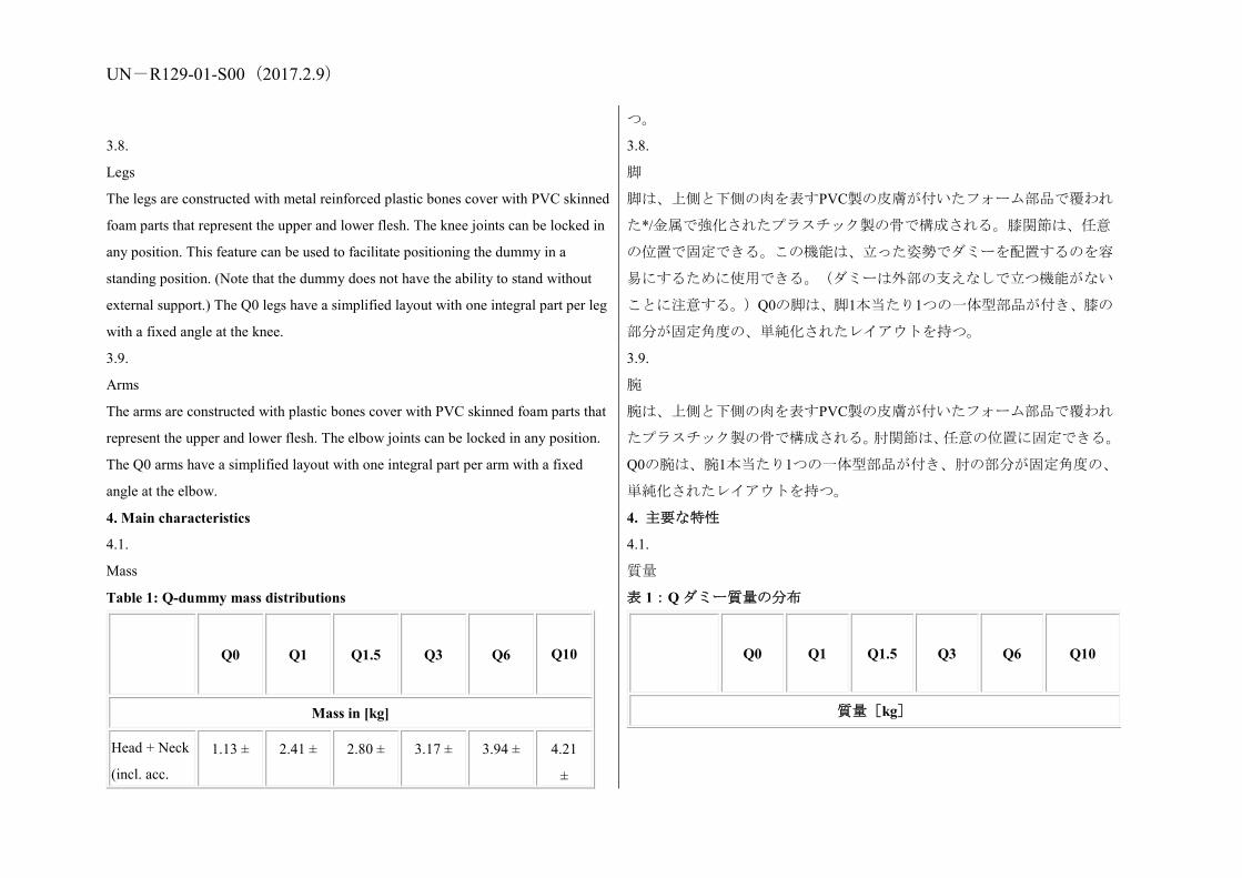
UN-R129-01-S00(2017.2.9)
つ。
3.8.
Legs
The legs are constructed with metal reinforced plastic bones cover with PVC skinned
foam parts that represent the upper and lower flesh. The knee joints can be locked in
any position. This feature can be used to facilitate positioning the dummy in a
standing position. (Note that the dummy does not have the ability to stand without
external support.) The Q0 legs have a simplified layout with one integral part per leg
with a fixed angle at the knee.
3.8.
脚
脚は、上側と下側の肉を表すPVC製の皮膚が付いたフォーム部品で覆われ
た*/金属で強化されたプラスチック製の骨で構成される。膝関節は、任意
の位置で固定できる。この機能は、立った姿勢でダミーを配置するのを容
易にするために使用できる。(ダミーは外部の支えなしで立つ機能がない
ことに注意する。)Q0の脚は、脚1本当たり1つの一体型部品が付き、膝の
部分が固定角度の、単純化されたレイアウトを持つ。
3.9.
Arms
The arms are constructed with plastic bones cover with PVC skinned foam parts that
represent the upper and lower flesh. The elbow joints can be locked in any position.
The Q0 arms have a simplified layout with one integral part per arm with a fixed
angle at the elbow.
3.9.
腕
腕は、上側と下側の肉を表すPVC製の皮膚が付いたフォーム部品で覆われ
たプラスチック製の骨で構成される。肘関節は、任意の位置に固定できる。
Q0の腕は、腕1本当たり1つの一体型部品が付き、肘の部分が固定角度の、
単純化されたレイアウトを持つ。
4. Main characteristics 4. 主要な特性
4.1.
Mass
Table 1: Q-dummy mass distributions
Q0 Q1 Q1.5 Q3 Q6 Q10
Mass in [kg]
Head + Neck
(incl. acc.
1.13 ± 2.41 ± 2.80 ± 3.17 ± 3.94 ± 4.21
±
4.1.
質量
表 1:Q ダミー質量の分布
Q0 Q1 Q1.5 Q3 Q6 Q10
質量[kg]

UN-R129-01-S00(2017.2.9) mount) 0.06 0.10 0.10 0.10 0.10 0.15
Torso (incl.
acc. mount
and chest
deflection
sensor)
1.40 ±
0.08
4.21 ±
0.25
4.74 ±
0.25
6.00 ±
0.30
9.07 ±
0.40
14.28
±
0.50
(incl.
suit)
Legs
(together)
0.58 ±
0.03
1.82 ±
0.20
2.06 ±
0.20
3.54 ±
0.10
6.90 ±
0.10
12.48
±
0.44
Arms
(together)
0.28 ±
0.02
0.89 ±
0.20
1.20 ±
0.20
1.48 ±
0.10
2.49 ±
0.10
3.98
±
0.20
Suit 0.08±
0.02
0.27 ±
0.05
0.30 ±
0.05
0.40 ±
0.10
0.55 ±
0.10
0.63 ±
0.10
Total 3.47 ±
0.21
9.6 ±
0.80
11.10 ±
0.80
14.59 ±
0.70
22.95 ±
0.80
35.58
±
1.39
The installation of Abdominal Pressure Twin Sensors (APTS) in frontal impact may
add up 0.2 kg to the Q1.5 and 0.5kg to the Q3, Q6 and Q10 dummies.
頭部+頸部
(加速度計
搭載を含む)
1.13 ±
0.06
2.41 ±
0.10
2.80 ±
0.10
3.17 ±
0.10
3.94 ±
0.10
4.21 ±
0.15
胴部(加速度
計搭載及び
胸部たわみ
センサを含
む)
1.40 ±
0.08
4.21 ±
0.25
4.74 ±
0.25
6.00 ±
0.30
9.07 ±
0.40
14.28 ±
0.50
(スーツ
を含む)
脚(両脚) 0.58 ±
0.03
1.82 ±
0.20
2.06 ±
0.20
3.54 ±
0.10
6.90 ±
0.10
12.48 ±
0.44
腕(両腕) 0.28 ±
0.02
0.89 ±
0.20
1.20 ±
0.20
1.48 ±
0.10
2.49 ±
0.10
3.98 ±
0.20
スーツ 0.08±
0.02
0.27 ±
0.05
0.30 ±
0.05
0.40 ±
0.10
0.55 ±
0.10
0.63 ± 0.10
合計 3.47 ±
0.21
9.6 ±
0.80
11.10 ±
0.80
14.59 ±
0.70
22.95 ±
0.80
35.58 ±
1.39
前面衝突における腹部圧力ツインセンサ(APTS)の搭載は、Q1.5 ダミー
には 0.2 kg まで、Q3、Q6 および Q10 ダミーには 0.5 kg までの質量が付加
される。

UN-R129-01-S00(2017.2.9)
4.2.
Principal dimensions
Figure 2: Main dimensions of dummy
Table 2: Q-dummy dimensions
4.2.
主要寸法
図2:ダミーの主要な寸法
表 2:Q ダミーの寸法

UN-R129-01-S00(2017.2.9)
N
o. Q0 Q1 Q1.5 Q3 Q6 Q10
Dimensions in mm
17 Seating height (head tilted forward)
355 ± 9
479 ± 9
499 ± 9
544 ± 9
601 ± 9
< 748 ± 9
18 Shoulder height (sitting)
225 ± 7
298 ± 7
309 ± 7
329 ± 7
362 ± 7
473 ± 7
Stature (head tilted forward)
- 740 ± 9
800 ± 9
985 ± 9
1143 ± 9
< 1443 ± 9
5 Chest depth - 114 ± 5
113 ± 5
146 ± 5
141 ± 5
171 ± 5
15 Shoulder width 230 ± 7
227 ± 7
227 ± 7
259 ± 7
305 ± 7
334.8 ± 7
Neck diameter 44 61.91 61.91 61.91 61.91 58.02 76.03
65.01 85.94
No
. Q0 Q1 Q1.5 Q3 Q6 Q10(
寸法単位はmm
17 座高
(頭部前傾) 355±9 479±9 499±9 544±9 601±9 < 748±9
18 肩の高さ
(着座時) 225±7 298±7 309±7 329±7 362±7 473±7
身長
(頭部前傾) - 740±9 800±9 985±9 1,143±9 < 1,443±9
5 胸深 - 114±5 113±5 146±5 141±5 171±5
15 肩幅 230±7 227±7 227±7 259±7 305±7 338±7
13 頸部直径 44 61.91 61.91 61.91 61.94 58.05 76.06
65.01 85.94
1 The neck diameter is taken as the diameter of the top and bottom plate of the Q dummy necks. Middle disks are 56.9 mm 2 Q6 neck disk at top 3 Q6 neck disk at bottom 4 Neck shield diameter 1 頸部直径は、Q ダミー頸部の上部プレートと底部プレートの直径。 中間のディスクは 56.9 mm。 2 Q6 の上部頸部ディスク。 3 Q6 の底部頸部ディスク。 4 頸部シールドの直径。

UN-R129-01-S00(2017.2.9)
12 Hip width - 191 ± 7
194 ± 7
200 ± 7
223 ± 7
270 ± 7
1 Back of buttocks to front of knees
130 ± 5
211 ± 5
235 ± 5
305 ± 5
366 ± 5
485.4 ± 5
2 Back of buttocks to popliteus
- 161 ± 5
185 ± 5
253 ± 5
299 ± 5
414.9 ± 5
21 Thigh height, sitting 69 72 79 92 114
Height of spacer device for positioning of dummy4
173 ±2
229 ± 2
237 ± 2
250 ± 2
270 ± 2
359 ± 2
1 See section 7.1.3.5.2.1: Height of spacer device (hinged board or similar flexible
device) equals shoulder height sitting minus thigh height sitting.
12 腰幅 - 191±7 194±7 200±7 223±7 270±7
1
臀部の後ろか
ら膝の前部ま
で
130 ± 5
211 ± 5
235 ± 5
305 ± 5
366 ± 5
485.4 ± 5
2 臀部の後ろか
ら膝窩筋まで - 161±5 185±5 253±5 299±5 414.9 ± 5
21 大腿部の高
さ、着座時 69 72 79 92 114
ダミーの位置
決めをするた
めのスペーサ
ー装置の高さ
4
229±2 237±2 250±2 270±2 359±2
1 頸部直径は、Q ダミー頸部の上部プレートと底部プレート
の直径。 中間のディスクは 56.9 mm。
2 Q6 の上部頸部ディスク。 3Q6 の底部頸部ディスク。 4 頸部シールドの直径。
Notes:
1.Adjustments of joints
Joints should be adjusted according to procedures included in the Q- dummy
manuals1 1 The technical specifications and detailed drawings of Q-dummy, and the technical
注:
1.関節の調節
関節は、Qダミーマニュアルに含まれている手順に従って調節すべきもの
とする。5
2.計装

UN-R129-01-S00(2017.2.9) specifications for their adjustment for the tests of this Regulation are deposited in a
transitory way on the website of the informal working group on Child Restraint
Systems (https://www2.unece.org/wiki/display/trans/Q-dummy+drawings) of the
UNECE, Palais de Nations, Geneva,
Switzerland. At the time of the adoption of this Regulation by the World Forum for
Harmonization of Vehicle Regulations (WP.29), the text restricting the use of the
drawings and technical specifications will be removed from the individual pages and
they will be reloaded on the above-mentioned website. After a time period needed by
the Informal Working Group to finalize the examination of the technical
specifications and drawings of dummies to cover the phase 2 of the Regulation, the
final and agreed drawings will be relocated in the
Mutual Resolution of the 1958 and 1998 Agreements, hosted in the website of the
World Forum WP.29.
ダミーのQファミリーの計装をQダミーマニュアルに含まれている手順に
従って設置し較正を施すものとする。5 5 Qダミーの技術仕様と詳細図ならびに本規則の試験のためのそれらの調
整に関する技術仕様は、UNECE(スイス、ジュネーブ、パレ・デ・ナシオ
ン)の改良型年少者用補助乗車装置に関するインフォーマル作業部会のウ
ェブサイト(https://www2.unece.org/wiki/display/trans/Q-dummy+drawings)
に一時的に置かれている。自動車基準調和世界フォーラム(WP.29)によ
る本規則の採択時に、図面及び技術仕様の使用を制限する文言は各頁から
削除され、図面及び技術仕様は上記のウェブサイトに再掲載される。イン
フォーマル作業部会が本規則のフェーズ2を対象に含めるためのダミーの
技術仕様と図面の検討を完了するために必要な期間が過ぎた後、最終の合
意済み図面は、世界フォーラムWP.29のウェブサイトに掲載されている
1958年協定及び1998年協定の相互決議に移動される。
2.Instrumentation
I Instrumentation in the Q family of dummies shall preferably be
installed and calibrated according to procedures contained in the
Q-dummy manuals1 and the APTS manual.
1 The technical specifications and detailed drawings of Q-dummy, and the technical
specifications for their adjustment for the tests of this Regulation are deposited in a
transitory way on the website of the informal working group on Child Restraint
Systems (https://www2.unece.org/wiki/display/trans/Q-dummy+drawings) of the
UNECE, Palais de Nations, Geneva,
Switzerland. At the time of the adoption of this Regulation by the World Forum for
Harmonization of Vehicle Regulations (WP.29), the text restricting the use of the
2.計装
ダミーのQファミリーの計装をQダミーマニュアルに含まれている手順に
従って設置し較正を施すものとする。1 1 Qダミーの技術仕様と詳細図ならびに本規則の試験のためのそれらの調
整に関する技術仕様は、UNECE(スイス、ジュネーブ、パレ・デ・ナシオ
ン)の改良型年少者用補助乗車装置に関するインフォーマル作業部会のウ
ェブサイト(https://www2.unece.org/wiki/display/trans/Q-dummy+drawings)
に一時的に置かれている。自動車基準調和世界フォーラム(WP.29)によ
る本規則の採択時に、図面及び技術仕様の使用を制限する文言は各頁から
削除され、図面及び技術仕様は上記のウェブサイトに再掲載される。イン
フォーマル作業部会が本規則のフェーズ2を対象に含めるためのダミーの
技術仕様と図面の検討を完了するために必要な期間が過ぎた後、最終の合
意済み図面は、世界フォーラムWP.29のウェブサイトに掲載されている
UN-R129-01-S00(2017.2.9) drawings and technical specifications will be removed from the individual pages and
they will be reloaded on the above-mentioned website. After a time period needed by
the Informal Working Group to finalize the examination of the technical
specifications and drawings of dummies to cover the phase 2 of the Regulation, the
final and agreed drawings will be relocated in the
Mutual Resolution of the 1958 and 1998 Agreements, hosted in the website of the
World Forum WP.29.
1958年協定及び1998年協定の相互決議に移動される。
Annex 9
Frontal impact test against a barrier
附則9
バリヤに対する前面衝突試験
1.1.
Testing ground
The test area shall be large enough to accommodate the run-up track, barrier and
technical installations necessary for the test. The last part of the track, for at least 5 m
before the barrier, shall be horizontal, flat and smooth.
1.1.
試験場
試験領域は、助走路、バリヤ及び試験に必要な技術設備を収容できる十分
な広さを有するものとする。助走路の最後の部分、すなわちバリヤの手前
の少なくとも5 mの区間は、水平かつ平坦で滑らかな面であるものとする。
1.2.
Barrier
The barrier consists of a block of reinforced concrete not less than 3 m wide at the
front and not less than 1.5 m high. The barrier shall be of such thickness that it
weighs at least 70 tonnes. The front face shall be vertical, perpendicular to the axis of
the run-up track, and covered with plywood boards 20 +/- 1 mm thick in good
condition. The barrier shall be either anchored in the ground or placed on the ground
with, if necessary, additional arresting devices to limit its
displacement. A barrier with different characteristics, but giving results at least
equally conclusive, may likewise be used.
1.2.
バリヤ
バリヤは、前面の幅が3 m以上、高さが1.5 m以上の鉄筋コンクリートのブ
ロックから成る。バリヤは、重量が少なくとも70 tになるような厚さをも
つものとする。正面は垂直、かつ助走路の軸に対して直角であるものとし、
また、厚さ20±1 mmのベニヤ板により良好な状態で覆うものとする。バリ
ヤは地中に埋め込むか、又は必要に応じて、移動を防止するための補助抑
止装置を使って地面に固定するものとする。異なる特性を有するバリヤで
あっても、少なくとも同等の結果を得られるものであれば、同様に使用す
ることができる。
1.3. 1.3.

UN-R129-01-S00(2017.2.9) Propulsion of the vehicle
At the moment of impact, the vehicle shall no longer be subjected to the action of
any additional steering or propelling device or devices. It shall reach the obstacle on
a course perpendicular to the collision wall; the maximum lateral disalignment
permitted between the vertical median line of the front of the vehicle and the vertical
median line of the collision wall is +/-30 cm.
車両の推進
衝突の瞬間に、車両はいかなる追加のステアリング装置又は推進装置の操
作も追加しないものとする。車両は、衝突壁面に対して直角をなすコース
上で、障害物に到達するものとする。
車両前部の垂直中心線と衝突壁面の垂直中心線の間の横方向のずれの最
大許容量は±30 cm である。
1.4.
State of the vehicle
1.4.
車両の状態
1.4.1.
The vehicle under test shall either be fitted with all the normal components and
equipment included in its unladen service weight or be in such a condition as to fulfil
this requirement in so far as the components and equipment of concern to the
passenger compartment and the distribution of the service weight of the vehicle as a
whole are concerned.
1.4.1.
試験を受ける車両は、その非積載状態の重量に含まれるすべての通常の構
成部品及び装備を装着するか、もしくは客室に付随する構成部品と装備及
び走行状態における車両全体の重量配分に関してこの要件を満たす状態
であるものとする。
1.4.2.
If the vehicle is driven by external means, the fuel installation shall be filled to at
least 90 per cent of its capacity, either with fuel or with a non-inflammable liquid,
having a density and a viscosity close to those of the fuel normally used. All other
systems (brake-fluid containers, radiator, etc.) shall be empty.
1.4.2.
車両を外部手段によって駆動する場合には、燃料装置は容量の少なくとも
90%まで、燃料もしくは通常使用される燃料に近い比重と粘度を有する不
燃性の液体を満たすものとする。その他すべてのシステム(ブレーキ液容
器、ラジエータなど)は空にするものとする。
1.4.3.
If the vehicle is driven by its own engine, the fuel tank shall be at least 90 per cent
full. All other liquid-holding tanks shall be filled to capacity.
1.4.3.
車両が自らのエンジンで走行する場合には、燃料タンクは容量の少なくと
も 90%まで満たすものとする。その他すべての液体用タンクは容量まで満
たすものとする。
1.4.4.
If the manufacturer so requests, the Technical Service responsible for conducting the
tests may allow the same vehicle as is used for tests prescribed by other Regulations
1.4.4.
メーカーからの要請がある場合には、試験を実施する技術機関は、本規則
以外の規則によって定められた試験(当該車両の構造に影響を及ぼしうる
UN-R129-01-S00(2017.2.9) (including tests capable of affecting its structure) to be used also for the tests
prescribed by this Regulation.
試験も含めて)に使用されたものと同一の車両を、本規則が定める試験に
も使用することを認めることができる。
1.5.
Impact velocity
The impact velocity shall be 50 +0/-2 km/h. However, if the test has been carried out
at a higher impact velocity and the vehicle has satisfied the conditions prescribed, the
test is considered satisfactory.
1.5.
衝突時の速度
衝突時の速度は、50 +0/-2 km/h とする。ただし、上記の速度を超える速度
で試験が実施され、その車両が規定条件を満たした場合には、その試験結
果は満足するものとみなされる。
1.6.
Measuring instruments
The instrument used to record the speed referred to in paragraph 1.5. above shall be
accurate within 1 per cent.
1.6.
測定機器
上記 1.5 項で述べた速度を記録するために使用する機器は、公差が 1%以下
の精度を有するものとする。
Annex 10
Rear impact test procedure
附則10
後面衝突試験手順
1. Installations, procedures and measuring instruments 1. 設備、手順及び測定機器
1.1.
Testing ground
The test area shall be large enough to accommodate the propulsion system of the
impactor and to permit after-impact displacement of the vehicle impacted and
installation of the test equipment. The part in which vehicle impact and displacement
occur shall be horizontal. (The slope shall be less than 3 per cent measured over any
length of one metre.)
1.1.
試験場
試験領域は、衝撃装置の推進システムを収容でき、かつ衝突される車両の
衝突後の移動と試験装置の設置が可能な十分な広さを有するものとする。
車両の衝突及び移動が起こる部分は水平であるものとする。(傾斜はどの
1 mの長さで測っても3%未満であるものとする。)
1.2.
Impactor
1.2.
衝撃装置
1.2.1.
The impactor shall be of steel and of rigid construction.
1.2.1.
衝撃装置は鋼鉄製で剛性構造を有するものとする。
UN-R129-01-S00(2017.2.9) 1.2.2.
The impacting surface shall be flat and at least 2,500 mm wide and 800 mm high. Its
edges shall be rounded to a radius of curvature of between 40 and 50 mm.
It shall be clad with a layer of plywood 20 +/- 1 mm thick.
1.2.2.
衝突面は、少なくとも幅が2,500 mm、高さが800 mmの平面とする。その縁
部は、40から50 mmの曲率半径の丸みを持つものとする。衝突面には、厚
さ20±1 mmのベニア板の層で被覆するものとする。
1.2.3.
At the moment of impact the following requirements shall be met:
1.2.3.
衝突の瞬間に、下記の要件を満たすものとする:
1.2.3.1.
The impacting surface shall be vertical and perpendicular to the median longitudinal
plane of the impacted vehicle;
1.2.3.1.
衝突面は、垂直で、かつ被衝突車両の中央縦断面に対して垂直であるもの
とする。
1.2.3.2.
The direction of movement of the impactor shall be substantially horizontal and
parallel to the median longitudinal plane of the impacted vehicle;
1.2.3.2.
衝撃装置の運動方向は、ほぼ水平方向で、かつ被衝突車両の中央縦断面と
平行であるものとする。
1.2.3.3.
The maximum lateral deviation permitted between the median vertical line of the
surface of the impactor and the median longitudinal plane of the impacted vehicle
shall be 300 mm. In addition, the impacting surface shall extend over the entire
width of the impacted vehicle;
1.2.3.3.
衝撃装置の表面の垂直中央線と被衝突車両の中央縦断面の間の横方向の
ずれの最大許容量は 300 mm とする。さらに、その衝突面は被衝突車両の
全幅をカバーするものとする。
1.2.3.4.
The ground clearance of the lower edge of the impacting surface shall be 175 +/- 25
mm.
1.2.3.4.
衝突面の下端の最低地上高は 175±25 mm とする。
1.3.
Propulsion of the impactor
The impactor may either be secured to a carriage (moving barrier) or form part of a
pendulum.
1.3.
衝撃装置の推進
衝撃装置は、運搬車(移動式バリヤ)に固定してもよいし、また、振り子
の一部となってもよい。
1.4.
Special provisions applicable where a moving barrier is used
1.4.
移動式バリヤを使用する場合に適用する特別規定

UN-R129-01-S00(2017.2.9) 1.4.1.
If the impactor is secured to a carriage (moving barrier) by a restraining element, the
latter shall be rigid and be incapable of being deformed by the impact; the carriage
shall, at the moment of impact, be capable of moving freely and no longer be subject
to the action of the propelling device.
1.4.1.
衝撃装置を拘束エレメントによって運搬車(移動式バリヤ)に取り付ける
場合には、運搬車は剛性を有し、衝突によって変形しないものとする。運
搬車は衝突の瞬間に自由に動くことができ、それ以後は推進装置の作用を
受けないものとする。
1.4.2.
The combined mass of carriage and impactor shall be 1,100 +/- 20 kg.
1.4.2.
運搬車と衝撃装置の合計質量は 1,100±20 kg とする。
1.5.
Special provisions applicable where a pendulum is used
1.5.
振り子を使用する場合に適用する特別規定
1.5.1.
The distance between the centre of the impacting surface and the axis of rotation of
the pendulum shall be not less than 5 m.
1.5.1.
衝突面の中心から振り子の回転軸までの距離は 5 m 以上とする。
1.5.2.
The impactor shall be freely suspended by rigid arms, rigidly secured to it. The
pendulum so constituted shall be substantially incapable of being deformed by the
impact.
1.5.2.
衝撃装置は剛性のアームにしっかりと取り付け、自由に動くように吊り下
げるものとする。このような構造を有する振り子は、衝突によって実質的
に変形しないものとする。
1.5.3.
A stopping device shall be incorporated in the pendulum to prevent any secondary
impact by the impactor on the test vehicle.
1.5.3.
衝撃装置による試験車両への二次衝突を防ぐために、振り子には停止装置
を組み込むものとする。
1.5.4.
At the moment of impact, the velocity of the centre of percussion of the pendulum
shall be between 30 and 32 km/h.
1.5.4.
衝撃の瞬間における振り子の衝撃中心の速度は 30 から 32 km/h とする。
1.5.5.
The reduced mass "mr" at the centre of percussion of the pendulum is defined as a
function of the total mass "m", of the distance "a"1 between the centre of percussion
1.5.5.
振り子の衝撃中心における減少質量「mr」は、総質量「m」、衝撃中心か
ら回転軸までの距離「a」1、及び重心から回転軸までの距離「1」の関数と
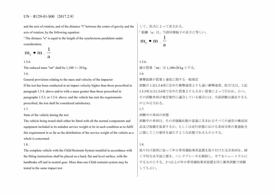
UN-R129-01-S00(2017.2.9) and the axis of rotation, and of the distance "l" between the centre of gravity and the
axis of rotation, by the following equation: 1 The distance "a" is equal to the length of the synchronous pendulum under
consideration.
して、次式によって表される。 1 距離「a」は、当該同期振子の長さに等しい。
1.5.6.
The reduced mass "mr" shall be 1,100 +/- 20 kg.
1.5.6.
減少質量「mr」は 1,100±20 kg とする。
1.6.
General provisions relating to the mass and velocity of the impactor
If the test has been conducted at an impact velocity higher than those prescribed in
paragraph 1.5.4. above and/or with a mass greater than those prescribed in
paragraphs 1.5.3. or 1.5.6. above, and the vehicle has met the requirements
prescribed, the test shall be considered satisfactory.
1.6.
衝撃装置の質量と速度に関する一般規定
試験が上記1.5.4項に定めた衝撃速度よりも速い衝撃速度、及び/又は、上記
1.5.3項又は1.5.6項で定めた質量よりも大きい質量によって行われ、かつ、
その試験車両が規定要件に適合している場合には、当該試験は満足するも
のとみなされる。
1.7.
State of the vehicle during the test
The vehicle being tested shall either be fitted with all the normal components and
equipment included in its unladen service weight or be in such condition as to fulfil
this requirement in so far as the distribution of the service weight of the vehicle as a
whole is concerned.
1.7.
試験中の車両の状態
試験中の車両は、その非積載状態の重量に含まれるすべての通常の構成部
品及び装備を装着するか、もしくは走行状態における車両全体の重量配分
に関してこの要件を満たすような状態であるものとする。
1.8.
The complete vehicle with the Child Restraint System installed in accordance with
the fitting instructions shall be placed on a hard, flat and level surface, with the
handbrake off and in neutral gear. More than one Child restraint system may be
tested in the same impact test.
1.8.
取り付け説明に従って年少者用補助乗車装置を取り付けた完全車両を、硬
く平坦な水平面に置き、ハンドブレーキを解除し、ギアをニュートラルに
するものとする。2つ以上の年少者用補助乗車装置を同じ衝突試験で試験
してもよい。

UN-R129-01-S00(2017.2.9) Annex 11
Type approval scheme (Flow chart ISO 9002:2000)
Notes:
0. Or an equivalent standard to this one with the permissible exclusion of the
requirements related to the concepts of design and development; point 7.3. of ISO
9002:2000 "Customer satisfaction and continual improvement"
1. These tests shall be done by Technical Services
2. Visit to the manufacturer for inspection and random sampling by the Type
Approval Authority or Technical Service
附則11
型式認可制度(フローチャート ISO 9002:2000)
注:
0. 又は、設計及び開発のコンセプトのISO 9002:2000の7.3項「顧客満足と
継続的改善」に関連する要件の除外が許容される、これと同等の規格。
1.これらの試験は技術機関が実施するものとする。
2.行政官庁又は技術機関が、検査及び無作為の抜取検査を行うために、メ
型式許可試験 および認定試験
COP 試験 3と立入り検査 2
COP 試験 3と立入り検査 2

UN-R129-01-S00(2017.2.9) (a) If there is no ISO 9002:2000: 2 times a year;
(b) If there is an ISO 9002:2000: 1 time a year.
3. Tests in accordance with Annex 13
(a) If there is no ISO 9002:2000:
(i) Of the Type Approval Authority or Technical Service during the visit of footnote
2a above;
(ii) Of the manufacturer between the visits of footnote 2b above;
(b) If there is an ISO 9002:2000: taken by the manufacturer, procedure checked
during visit of footnote 2b above.
ーカー施設に立ち入る。
(a) ISO 9002:2000認証を受けていない場合:1年に2回、
(b) ISO 9002:2000認証を受けている場合:1年に1回。
3.附則13に準拠した試験
(a) ISO 9002:2000認証を受けていない場合:
(i) 行政官庁又は技術機関が上記脚注2aの立入り検査中に実施、
(ii) メーカーが上記脚注2bの次回の立入り検査までの間に実施。
(b) ISO 9002:2000 認証を受けている場合:メーカーが実施し、上記脚注 2b
の立入り検査中に手順がチェックされる。
Annex 12
Control of conformity of production
附則12
生産の適合性の管理
1. Tests
Child Restraint Systems shall be required to demonstrate compliance with the
requirements on which the following tests are based:
1. 試験
年少者用補助乗車装置が、以下の試験の基準となっている要件に適合して
いることを証明することが要求されるものとする。
1.1.
Verification of the locking threshold and durability of emergency locking retractors
According to the provisions of paragraph 7.2.4.3. of this Regulation in the most
unfavourable direction as appropriate after having undergone the durability testing
detailed in paragraphs 7.2.4.2., 7.2.4.4. and 7.2.4.5. of this Regulation as a
requirement of paragraph 6.7.3.2.6. of this Regulation.
1.1.
緊急ロック式巻取装置のロック閾値と耐久性の検証
本規則の 6.7.3.2.6 項の要件として本規則の 7.2.4.2 項、7.2.4.4 項及び 7.2.4.5
項に規定する耐久性試験を実施した後、該当する最も不利な方向で本規則
の 7.2.4.3 項の規定に従う。
1.2.
Verification of the durability of automatically locking retractors
According to the provisions of paragraph 7.2.4.2. of this Regulation supplemented by
the tests in paragraphs 7.2.4.4. and 7.2.4.5. of this Regulation as a requirement of
paragraph 6.7.3.1.3. of this Regulation.
1.2.
自動ロック式巻取装置の耐久性の検証
本規則の 6.7.3.1.3 項の要件として本規則の 7.2.4.4 項及び 7.2.4.5 項の試験
で補足した本規則の 7.2.4.2 項の規定に従う。

UN-R129-01-S00(2017.2.9) 1.3.
Test for strength of straps after conditioning
According to the procedure described in paragraph 6.7.4.2. of this Regulation after
conditioning according to the requirements of paragraphs 7.2.5.2.1. to 7.2.5.2.5. of
this Regulation.
1.3.
コンディショニング後の帯部の強度試験
本規則の 7.2.5.2.1 項から 7.2.5.2.5 項の要件に従うコンディショニングの
後、本規則の 6.7.4.2 項で規定する手順に従う。
1.3.1.
Test for strength of straps after abrasion
According to the procedure described in paragraph 6.7.4.2. of this Regulation after
conditioning according to the requirements described in paragraph 7.2.5.2.6. of this
Regulation.
1.3.1.
摩擦後の帯部の強度試験
本規則の 7.2.5.2.6 項の要件に従うコンディショニングの後、本規則の
6.7.4.2 項で説明されている手順に従う。
1.4.
Microslip test
According to the procedure described in paragraph 7.2.3. of this Regulation.
1.4.
マイクロスリップ試験
本規則の 7.2.3 項で説明されている手順に従う。
1.5.
Energy absorption
According to the provisions of paragraph 6.6.2. of this Regulation.
1.5.
エネルギー吸収
本規則の 6.6.2 項の規定に従う。
1.6.
Verification of the performance requirements of the Child Restraint System when
subjected to the appropriate dynamic test:
According to the provisions set out in paragraph 7.1.3. of this Regulation with any
buckle having been pre-conditioned according to the requirements of paragraph
6.7.1.6. of this Regulation such that the appropriate requirements of paragraph 6.6.4.
of this Regulation (for the overall performance of the Child Restraint System) and
paragraph 6.7.1.7.1. of this Regulation (for the performance of any buckle under
load) are complied with.
1.6.
該当する動的試験の対象となる年少者用補助乗車装置の性能要件の検証
本規則の6.6.4項(年少者用補助乗車装置の全性能)及び本規則の6.7.1.7.1
項(負荷状態でのバックルの性能)の該当する要件に適合するように、本
規則の6.7.1.6項の要件に従ってあらかじめコンディショニングを施したバ
ックルを用いて、本規則の7.1.3項の規定に従う。
1.7. 1.7.

UN-R129-01-S00(2017.2.9) Temperature test
According to the provisions of paragraph 6.6.5. of this Regulation.
温度試験
本規則の 6.6.5 項の規定に従う。
2. Test frequency and results 2. 試験の頻度と結果
2.1.
The frequency of testing to the requirements of paragraphs 1.1. to 1.5. and 1.7. above
shall be on a statistically controlled and random basis in accordance with one of the
regular quality assurance procedure, and shall be conducted at least once per year.
2.1.
上記1.1項から1.5項及び1.7項の要件による試験の頻度は、定期的な品質保
証手順の1つに従って統計的に管理された無作為条件で行うものとし、少
なくとも1年に1回は実施するものとする。
2.2.
Minimum conditions for the control of conformity of Child Restraint Systems of
categories "Universal", in relation to the dynamic tests according to paragraph 1.6.
above.
2.2.
上記1.6項に準拠した動的試験に関する、「汎用」区分の年少者用補助乗車
装置の適合性の管理のための最低条件。
2.2.1.
Batch control for the Child Restraint Systems
2.2.1.
年少者用補助乗車装置のバッチ管理法
2.2.1.1.
The holder of an approval shall divide the Child Restraint Systems into batches
which are as uniform as possible in regard to raw material or intermediate products
involved in their manufacture (different colour of shell, different manufacture of
harness) and in regard to production conditions. The numbers in a batch shall not
exceed 5,000 units.
In agreement with the relevant authorities the tests can be carried out by the
Technical Service or under the responsibility of the holder of an approval.
2.2.1.1.
認可の保有者は、年少者用補助乗車装置を、その製造に使われた原材料又
は中間製品に関し(シェルの色違い、ハーネスの製造の違い)、及び生産
条件に関し、できる限り均質なバッチに分割するものとする。1つのバッ
チの個数は5,000を超えないものとする。
所管当局と合意すれば、試験は、技術機関が実施することも、認可保有者
の責任の下で実施することもできる。
2.2.1.2.
A sample shall be taken in each batch in accordance with the provisions of paragraph
2.2.1.4. below from a minimum of 20 per cent of the batch quantity, which has to be
produced of the actual batch.
2.2.1.2.
バッチ数量の少なくとも20%を対象に、下記2.2.1.4項の規定に従って各バ
ッチにつき1個のサンプルを採取するものとする。各サンプルは、実際の
バッチから生産されたものでなければならない。
2.2.1.3. 2.2.1.3.

UN-R129-01-S00(2017.2.9) The characteristics of the Child Restraint Systems and the number of dynamic tests
to be conducted are given in paragraph 2.2.1.4. below
年少者用補助乗車装置の特性と実施すべき動的試験の回数は下記 2.2.1.4
項で説明する。
2.2.1.4.
In order to be accepted, a batch of Child Restraint Systems shall satisfy the following
conditions.
Number in the batch
Number of samples/ Child
Restraint Systems
characteristics
Combined number of
samples Acceptance criteria
Rejection criteria
Degree of control rigour
N<500 1st = 1MH 1 0 -
Normal 2nd = 1MH 2 1 2
500<N<5,0
00
1st =
1MH+1LH 2 0 2
Normal 2nd =
1MH+1LH 4 1 2
N<500 1st = 2MH 2 0 2
Strengthened 2nd = 2MH 4 1 2
500<N<5,0
00
1st =
2MH+2LH 4 0 2
Strengthened 2nd =
2MH+2LH 8 1 2
Notes:
2.2.1.4.
年少者用補助乗車装置のバッチが合格するためには以下の条件を満たす
ものとする。
バッチ内の個数
供試品数/年少
者用補助乗車
装置の特性
供試品
合計数 合格基準
不合格基
準
管理の厳
格度
N<500 1回目 = 1MH 1 0 -
通常 2回目 = 1MH 2 1 2
500<N<5,000
1回目 =
1MH+1LH 2 0 2
通常 2回目 =
1MH+1LH 4 1 2
N<500 1回目 = 2MH 2 0 2
強化 2回目 = 2MH 4 1 2
500<N<5,000
1回目 =
2MH+2LH 4 0 2
強化 2回目 =
2MH+2LH 8 1 2
注:
MHは、厳しい方の構成(認可又は認可の拡大で得られた最悪の結果)を

UN-R129-01-S00(2017.2.9) MH means harder configuration (the least good results obtained in approval or
extension of approval)
LH signifies a less hard configuration.
This dual sampling plan functions as follows:
For a normal control, if the first sample does not contain any defective units the
batch is accepted without testing a second sample. If it contains two defective units
the batch is rejected.
Finally, if it contains one defective unit a second sample is extracted and it is the
cumulative number, which shall satisfy the condition of column 5 of the table above.
There is a change from normal control to strengthened control if, out of 5
consecutive batches, two are rejected. Normal control is resumed if 5 consecutive
batches are accepted.
If any batch is rejected, the production is considered to be non-conforming and the
batch shall not be released.
If two consecutive batches subjected to the strengthened control are rejected, the
provisions of paragraph 13. of this Regulation are applied.
いう。
LHは、厳しくない方の構成をいう。
この二重サンプリングプランは次のように機能する。
通常の管理時に、最初の供試品に欠陥品が含まれていなければ、2つ目の
供試品を試験しないで、そのバッチを合格とする。最初の供試品に2つの
欠陥品が含まれている場合、そのバッチは不合格とする。最後に、最初の
供試品に欠陥品が1つある場合は、2つ目のサンプルを採取し、累積数で上
表の5列目の条件を満たすものとする。
5つの連続したバッチの中で2つのバッチが不合格になった場合、通常管理
から強化管理へ変化する。5つの連続したバッチが合格した場合は、通常
管理に戻る。
バッチが不合格になった場合、生産が不適合であるとみなし、そのバッチ
は市場に出さないものとする。
強化管理中に 2 つの連続したバッチが不合格になった場合、本規則の 13
項の規定を適用する。
2.2.1.5.
The control of Child Restraint Systems conformity is undertaken starting with the
batch manufactured after the first batch which was subjected to production
qualification.
2.2.1.5.
年少者用補助乗車装置の適合性の管理は、生産認定の対象となった最初の
バッチの後に製造されたバッチから実施する。
2.2.1.6.
The test results described in paragraph 2.2.1.4. above shall not exceed L, where L is
the limit value prescribed for each approval test.
2.2.1.6.
上記 2.2.1.4 項で説明されている試験結果は、L を超えないものとする。こ
こで L は、各認可試験に規定されている限界値である。
2.2.2.
Continuous control
2.2.2.
連続管理法
2.2.2.1. 2.2.2.1.

UN-R129-01-S00(2017.2.9) The holder of an approval shall be obliged to carry out continuous quality control of
his manufacturing process on a statistical basis and by sampling. In agreement with
the relevant authorities, the tests can be carried out by the Technical Service or under
the responsibility of the holder of an approval which is responsible for the
traceability of the product.
認可の保有者は、抜取検査を下に、統計的な方法で、製造工程の継続的品
質管理を実施することを義務付けられるものとする。所管当局と合意すれ
ば、試験は技術機関が実施することも、製品のトレーサビリティについて
責任を負う認可保有者の責任の下で実施することもできる。
2.2.2.2.
The samples shall be taken in accordance with the provisions of paragraph 2.2.2.4.
below.
2.2.2.2.
供試品は、下記 2.2.2.4 項の規定に従って採取するものとする。
2.2.2.3.
The characteristic of the Child Restraint Systems is taken at random and the tests to
be carried out are described in paragraph 2.2.2.4. below.
2.2.2.3.
年少者用補助乗車装置の特性は、無作為に採取し、実施すべき試験は下記
2.2.2.4 項に記載されている。
2.2.2.4.
Control shall meet the following requirements:
Child Restraint Systems taken Degree of control
rigour
0.02 per cent means one Child Restraint System
taken from every 5,000 manufactured Normal
0.05 per cent means one Child Restraint System
taken from every 2,000 manufactured Strengthened
This dual sampling plan functions as follows:
If the Child Restraint System is considered to conform, the production conforms.
If the Child Restraint System does not meet the requirements, a second Child
Restraint System shall be taken.
If the second Child Restraint System meets the requirements, the production
2.2.2.4.
管理は以下の要件に適合するものとする。
採取する年少者用補助乗車装置 管理の厳格度
0.02%は、5,000個製造されるたびに、1個の年少者用補
助乗車装置を採取することをいう 通常
0.05%は、2,000個製造されるたびに、1個の年少者用補
助乗車装置を採取することをいう 強化
この二重サンプリングプランは次のように機能する。
年少者用補助乗車装置が要件に適合しているとみなされば、その生産は適
合とする。
年少者用補助乗車装置が要件を満たさない場合、2つ目の年少者用補助乗
車装置を採取するものとする。

UN-R129-01-S00(2017.2.9) conforms.
If both (the first and the second) Child Restraint Systems do not meet the
requirements, the production does not conform and Child Restraint Systems that are
likely to present the same failure shall be withdrawn and necessary steps shall be
taken to re-establish the conformity of the production.
Strengthened control will replace normal control if, out of 10,000 Child Restraint
Systems manufactured consecutively, the production has to be withdrawn twice.
Normal control is resumed if 10,000 Child Restraint Systems manufactured
consecutively are considered to conform.
If production subjected to the strengthened control has been withdrawn on two
consecutive occasions, the provisions of paragraph 13. of this Regulation are applied.
2つ目の年少者用補助乗車装置が要件を満たせば、その生産は適合とする。
両方(1つ目と2つ目)の年少者用補助乗車装置が要件を満たさない場合、
その生産は要件に適合せず、同じ故障が確認される可能性の高い年少者用
補助乗車装置は生産を中止し、生産の適合性を再確立するために必要な方
策を取るものとする。
連続して製造された10,000個の年少者用補助乗車装置の中で、生産を2回中
止しなければならなかった場合、通常管理に代わって強化管理を実施す
る。
連続して製造された10,000個の年少者用補助乗車装置が要件に適合してい
るとみなされた場合、通常管理に戻る。
強化管理の対象となった生産中、2 回連続して生産が中止になった場合は、
本規則の 13 項の規定を適用する。
2.2.2.5.
The continuous control of Child Restraint Systems is undertaken starting after the
production qualification.
2.2.2.5.
年少者用補助乗車装置の連続管理は、生産認定の後に開始する。
2.2.2.6.
The test results described in paragraph 2.2.2.4. above shall not exceed L, where L is
the limit value prescribed for each approval test.
2.2.2.6.
上記 2.2.2.4 項で説明されている試験結果は、L を超えないものとする。こ
こで L は、各認可試験に規定された限界値である。
2.3.
For Specific vehicle ECRS devices according to paragraph 2.1.2.4.1. above, the
Enhanced Child Restraint System manufacturer may choose Conformity of
Production procedures according to either paragraph 2.2. above, on a test bench, or
paragraphs 2.3.1. and 2.3.2. below , in a vehicle body shell.
2.3.
上記2.1.2.4.1項に従った「特定車両用ISOFIX」装置については、改良型年
少者用補助乗車装置メーカーは、上記2.2項に基づき試験台で行うか、下記
2.3.1項及び2.3.2項に基づき車両ボディシェルで行うか、いずれかの生産の
適合性手順を選ぶことができる。
2.3.1.
For Specific vehicle ECRS devices, the following test frequencies shall apply once
every eight weeks:
2.3.1.
「特定車両用ISOFIX」ECRS装置については、8週間ごとに1回という試験
頻度を適用するものとする。
UN-R129-01-S00(2017.2.9) At each test all requirements according to paragraphs 6.6.4. and 6.7.1.7.1. of this
Regulation shall be fulfilled. If all tests during one year show satisfactory results, the
manufacturer may, after agreement with the Type Approval Authority, reduce the
frequencies as follows: once every 16 weeks.
However, a minimum frequency of one test per year shall be permitted where annual
production is 1,000 Child Restraint Systems or less.
いずれの試験でも、本規則の6.6.4項及び6.7.1.7.1項に基づく全要件を満た
すものとする。1年間にわたりすべての試験で満足できる結果が得られた
場合、メーカーは、行政官庁と合意の後、16週間ごとに1回に、試験頻度
を減らしてもよい。
ただし、年間の生産個数が 1,000 個以下である年少者用補助乗車装置の場
合は、1 年に最低 1 回の頻度でもよい。
2.3.2.
Where a test sample fails a particular test to which it has been subjected, a further
test to the same requirement shall be carried out on at least three other samples. In
the case of dynamic tests if one of the latter fails, the production is considered to be
non-conforming and the frequency shall be raised to the higher one if the lower one
was used according to paragraph 2.3. above and necessary steps shall be taken to
re-establish the conformity of the production.
2.3.2.
試験片が対象となった特定の試験に合格しない場合、同一要件による追加
試験を少なくとも他の3個の供試品に対して実施するものとする。動的試
験の場合、追加の供試品のうち1個が合格しなかった場合、その生産は不
適合とみなし、上記2.3項に従って少ない試験頻度が使用されている場合、
試験頻度を高くするものとし、生産の適合性を再確立するために必要な方
策を取るものとする。
2.4.
When production is found to be non-conforming according to paragraphs 2.2.1.4.,
2.2.2.4. or 2.3.2. above, the holder of the approval or his duly accredited
representative shall:
2.4.
上記 2.2.1.4 項、2.2.2.4 項又は 2.3.2 項に従って、生産が不適合であること
が確認された場合、認可の保有者又は正規の委任代理人は、以下のことを
行うものとする。
2.4.1.
Notify the Type Approval Authority which has granted type approval indicating
what steps have been taken to re-establish the conformity of production.
2.4.1.
型式認可を付与した行政官庁に、生産の適合性を再び確立するために取っ
た方策を明記して通知すること。
2.5.
The manufacturer shall advise the Type Approval Authority on a quarterly basis, the
volume of products produced against each approval number, providing a means of
identifying which products correspond to that approval number.
2.5.
メーカーは、四半期ごとに、各認可番号により生産された製品の量を、ど
の製品が当該認可番号に該当するかを識別する方法を明記して、行政官庁
に報告するものとする。
Annex 13 附則13

UN-R129-01-S00(2017.2.9) Test of energy absorbing material エネルギー吸収材の試験
1. Headform 1. ヘッドフォーム
1.1.
The headform shall consist of a solid wooden hemisphere with an added smaller
spherical segment as shown in Figure A below. It shall be constructed so that it can
be dropped freely along the axis marked and it shall have provision for mounting an
accelerometer in order to measure the acceleration along the direction of fall.
1.1.
ヘッドフォームは、下記図Aに示すように、小さな球状部分を加えた硬い
木製の半球から成るものとする。これは表示した軸に沿って自由落下がで
きるように製作するものとし、落下方向の加速度を測定する加速度計を取
り付けるための装備があるものとする。
1.2.
The headform shall have a total mass, including the accelerometer of 2.75 +/- 0.05
kg.
Figure A: Headform
1.2.
ヘッドフォームは、加速度計を含めて、総質量を2.75±0.05 kgとする。
図 A:ヘッドフォーム
2. Instrumentation
The acceleration shall be recorded during the test, using equipment in accordance
with channel frequency class 1000 as specified in the latest version of ISO 6487.
2. 計装
試験中は、ISO 6487の最新版に指定されているチャネル周波数等級1000に
従う機器を用いて、加速度を記録するものとする。
3. Procedure 3. 手順

UN-R129-01-S00(2017.2.9) 3.1.
The child restraint shall be placed in the region of impact on a rigid flat surface,
whose minimum dimensions are 500 x 500 mm, so that the direction of impact is
perpendicular to the inner surface of the child restraint system in the area of impact
3.1.
年少者用補助乗車装置を、剛性の平面上で最小面積が500×500 mmの衝撃
区域内に、衝撃の方向が当該衝撃区域内の年少者用補助乗車装置の内側表
面に垂直になるように配置するものとする。
3.2.
Raise the headform to a height of 100 -0/+5 mm from the respective upper surfaces
of the assembled Child Restraint System to the lowest point on the headform, and
allow it to fall. Record the acceleration experienced by the headform during impact.
3.2.
ヘッドフォームを、組み立てられた年少者用補助乗車装置の各上面からヘ
ッドフォームの最下点までの距離が100 -0/+5 mmとなる高さまで持ち上
げ、落下させる。衝撃中にヘッドフォームが受けた加速度を記録する。
Annex 14
Method of defining head impact area of devices with backrests and for
rearward-facing devices defining the minimum size of side wings
附則14
背もたれ付き装置の頭部衝突面積及び後向き装置のサイドウイングの最
小サイズの決定方法
1.
Place the device on the test bench described in Annex 6. Reclinable devices shall be
set in the most upright position. Place the smallest manikin in the device in
accordance with the manufacturer’s instructions. Mark a point "A" on the backrest
on the same horizontal level as the shoulder of the smallest manikin at a point 2 cm
inside the outer edge of the arm. All internal surfaces above the horizontal plane
passing through point A, shall be tested in accordance with Annex 13. This area shall
include the backrest and side wings, including the inner edges (zone of radius) of the
side wings. In the case of carrycot devices where a symmetrical installation of the
dummy is not possible according to the device and manufacturer instructions, the
area complying with Annex 13 shall be all internal surfaces above a point "A", as
previously defined, in the head direction, when measured with this dummy in the
carrycot in its worst position consistent with the manufacturer instructions and the
carrycot positioned on the test bench..
1.
装置を附則 6 に記載されたテストベンチに置く。リクライニング可能な装
置は、最も直立した位置に設定するものとする。最小のマネキンを、メー
カーの指示に従って装置内に置く。背もたれ上で、最小のマネキンの肩と
同じ水平位置において、腕の外端より 2 cm 内側の点に点「A」をマークす
る。点 A を通る水平面より上にあるすべての内側表面を附則 13 に従って
テストするものとする。当該区域は、サイドウイングの内端(半径領域)
を含め、背もたれおよびサイドウイングを含むものとする。キャリコット
装置のうち、装置およびメーカーの指示によりダミーの対称的な取り付け
が不可能なものの場合、附則 13 に適合する区域は、このダミーをメーカ
ーの指示に基づくキャリコットの最悪位置に置き、かつキャリコットをテ
ストベンチに載せた状態で測定したときに、その前に定めた点「A」より
上にある頭部方向におけるすべての内側表面とする。
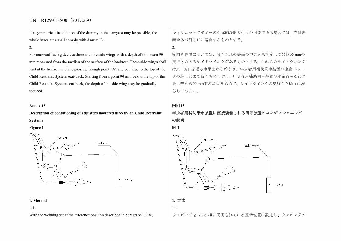
UN-R129-01-S00(2017.2.9) If a symmetrical installation of the dummy in the carrycot may be possible, the
whole inner area shall comply with Annex 13.
キャリコットにダミーの対称的な取り付けが可能である場合には、内側表
面全体が附則13に適合するものとする。
2.
For rearward-facing devices there shall be side wings with a depth of minimum 90
mm measured from the median of the surface of the backrest. These side wings shall
start at the horizontal plane passing through point "A" and continue to the top of the
Child Restraint System seat-back. Starting from a point 90 mm below the top of the
Child Restraint System seat-back, the depth of the side wing may be gradually
reduced.
2.
後向き装置については、背もたれの表面の中央から測定して最低90 mmの
奥行きのあるサイドウイングがあるものとする。これらのサイドウィング
は点「A」を通る水平面から始まり、年少者用補助乗車装置の座席バッ・
クの最上部まで続くものとする。年少者用補助乗車装置の座席背もたれの
最上部から90 mm下の点より始めて、サイドウイングの奥行きを徐々に減
らしてもよい。
Annex 15
Description of conditioning of adjusters mounted directly on Child Restraint
Systems
Figure 1
附則15
年少者用補助乗車装置に直接装着される調節装置のコンディショニング
の説明
図 1
1. Method 1. 方法
1.1.
With the webbing set at the reference position described in paragraph 7.2.6.,
1.1.
ウェビングを 7.2.6 項に説明されている基準位置に設定し、ウェビングの
UN-R129-01-S00(2017.2.9) withdraw at least 50 mm of webbing from the integral harness by pulling on the free
end of the webbing.
固定されていない先端を引っ張って、ウェビングを一体型ハーネスから少
なくとも 50 mm 引き出す。
1.2.
Attach the adjusted part of the integral harness to the pulling device A.
1.2.
一体型ハーネスの調節した部分を引き出し装置 A に取り付ける。
1.3.
Activate the adjuster and pull at least 150 mm of webbing into the integral harness.
This represents half of one cycle and puts pulling device A to the maximum webbing
extraction position.
1.3.
調節装置を作動させ、少なくともウェビング 150 mm を一体型ハーネスの
中に引き込む。これは 1 サイクルの半分にあたり、引き出し装置 A を最大
ウェビング引き出し位置に付けることになる。
1.4.
Connect free end of webbing to pulling device B.
1.4.
ウェビングの固定されていない先端を引き出し装置 B に接続する。
2.
The cycle is:
2.
サイクル
2.1.
Pull B at least 150 mm whilst A exerts no tension on the integral harness.
2.1.
A が一体型ハーネスに張力を掛けない状態で、B を少なくとも 150 mm 引
っ張る。
2.2.
Activate the adjusters and pull A whilst B exerts no tension on the free end of the
webbing.
2.2.
B がウェビングの固定されていない先端に張力を掛けない状態で、調節装
置を作動させ、A を引っ張る。
2.3.
At the end of stroke, de-activate the adjuster.
2.3.
ストロークが終了したら、調節装置の作動を停止させる。
2.4.
Repeat cycle as specified in paragraph 6.7.2.7. of this Regulation.
2.4.
本規則の 6.7.2.7 項に指定されているサイクルを繰り返す。
Annex 16
Typical buckle strength test device
附則16
典型的なバックル強度試験装置

UN-R129-01-S00(2017.2.9)
Annex 17
Determination of performance criteria
附則17
性能基準の決定
1. Head Performance Criterion (HPC) 1. 頭部性能基準(HPC)
1.1.
This criterion is considered to be satisfied when, during the test, there is no contact
1.1.
この基準は、試験中に、頭部がいかなる車両構成部品とも接触しないとき

UN-R129-01-S00(2017.2.9) between the head and any vehicle component. に満たされるとみなされる。
1.2.
If that is not the case, a calculation of the value of HPC is made, on the basis of the
acceleration (a),1 by the following expression: 1 The acceleration (a) referring to the centre of gravity is calculated from the triaxial
components of the acceleration measured with a CFC of 1,000.
In which:
1.2.
そうでない場合、HPCの値の計算は、以下の式を用いて、加速度(a)1に
基づいて行われる。 1 重心を基準とする加速度(a)は、CFCが1,000で測定される加速度の三軸
構成要素から計算される。
ここで、
1.2.1.
The term "a" is the resultant acceleration is measured in units of gravity, g (1 g =
9,81 m/s2);
1.2.1.
「a」とは、重力の単位gで測定される、結果として生じた加速度である(1
g = 9.81 m/s2)。
1.2.2.
If the beginning of the head contact can be determined satisfactorily, t1 and t2 are the
two time instants, expressed in seconds, defining an interval between the beginning
of the head contact and the end of the recording for which the value of HPC is
maximum;
1.2.2.
頭部接触の開始が十分に判断できる場合、t1 と t2 は、頭部接触の開始時点
から HPC の値が最大となる記録の終了までの間隔を定義する、秒単位で
表される 2 つの瞬間である。
1.2.3.
If the beginning of the head contact cannot be determined, t1 and t2 are the two time
instants, expressed in seconds, defining a time interval between the beginning and
the end of the recording for which the value of HPC is maximum;
1.2.3.
頭部接触の開始が判断できない場合、t1と t2は、HPC の値が最大となる記
録の開始から終了までの間隔を定義する、秒単位で表される 2 つの瞬間で
ある。
1.2.4.
Values of HPC for which the time interval (t1 - t2) is greater than 15 ms are ignored
1.2.4.
時間間隔(t1 - t2)が 15 ms より長い HPC の値は、最大値の計算目的では無

UN-R129-01-S00(2017.2.9) for the purposes of calculating the maximum value. 視される。
1.3.
The value of the resultant head acceleration during forward impact which is
exceeded for 3 ms cumulatively is calculated from the resultant head acceleration.
1.3.
累積的に3 msを超える前方衝撃中に、結果として生まれる頭部加速度の値
は、結果として生じる頭部加速度から計算される。
Annex 18
Geometrical dimensions of i-Size Child Restraint Systems
Figure 1
Stature cm
Sitting height cm
Shoulder breadth cm
Hip breadth cm Shoulder height cm
A B C D E
95%ile 95%ile 95%ile 5%ile 95%ile
40 NA NA NA NA NA
45 39.0 12.1 14.2 27.4 29.0
50 40.5 14.1 14.8 27.6 29.2
55 42.0 16.1 15.4 27.8 29.4
60 43.5 18.1 16.0 28.0 29.6
附則 18
アイサイズ改良型年少者用補助乗車装置の幾何学的寸法
図 1
身長(cm) 座高(cm) 肩幅(cm) ヒップ幅(cm)
最小の肩高さ(cm)
最大の肩高さ
(cm) A B C D E1 E2
95パーセン
タイル
95パーセン
タイル
95パーセン
タイル
5パーセ
ンタイル
95パーセ
ンタイル
≦40 <27.4 NA
45 39.0 12.1 14.2 27.4 29.0
50 40.5 14.1 14.8 27.6 29.2
55 42.0 16.1 15.4 27.8 29.4

UN-R129-01-S00(2017.2.9) 65 45.0 20.1 17.2 28.2 29.8
70 47.1 22.1 18.4 28.3 30.0
75 49.2 24.1 19.6 28.4 31.3
80 51.3 26.1 20.8 29.2 32.6
85 53.4 26.9 22.0 30.0 33.9
90 55.5 27.7 22.5 30.8 35.2
95 57.6 28.5 23.0 31.6 36.5
100 59.7 29.3 23.5 32.4 37.8
105 61.8 30.1 24.9 33.2 39.1
110 63.9 30.9 26.3 34.0 40.4
115 66.0 32.1 27.7 35.5 41.7
120 68.1 33.3 29.1 37.0 43.0
125 70.2 34.5 30.5 38.5 44.3
130 72.3 35.7 31.9 40.0 46.1
135 74.4 36.9 33.3 41.5 47.9
140 76.5 38.1 34.7 43.0 49.7
145 78.6 39.3 36.3 44.5 51.5
150 81.1 41.5 37.9 46.3 53.3
All lateral dimensions are measured under a contact force of 50 N with the device
described in Figure 2 of this annex and the following tolerances will applied:
60 43.5 18.1 16.0 28.0 29.6
65 45.0 20.1 17.2 28.2 29.8
70 47.1 22.1 18.4 28.3 30.0
75 49.2 24.1 19.6 28.4 31.3
80 51.3 26.1 20.8 29.2 32.6
85 53.4 26.9 22.0 30.0 33.9
90 55.5 27.7 22.5 30.8 35.2
95 57.6 28.5 23.0 31.6 36.5
100 59.7 29.3 23.5 32.4 37.8
105 61.8 30.1 24.9 33.2 39.1
110 63.9 30.9 26.3 34.0 40.4
115 66.0 32.1 27.7 35.5 41.7
120 68.1 33.3 29.1 37.0 43.0
125 70.2 34.5 30.5 38.5 44.3
130 72.3 35.7 31.9 40.0 46.1
135 74.4 36.9 33.3 41.5 47.9
140 76.5 38.1 34.7 43.0 49.7
145 78.6 39.3 36.3 44.5 51.5
150 81.1 41.5 37.9 46.3 53.3
横寸法は全て、本附則の図2に説明されている装置を使って50 Nの接触力

UN-R129-01-S00(2017.2.9) Minimum Sitting height:
From 40 to 87 cm B - 5 per centile
From 87 cm and up B - 10 per centile,
Minimum shoulder breadth: C -0+2 cm
Minimum hip breadth: D -0+2 cm
Minimum shoulder height (5 per centile): E1 -2+0 cm
Maximum shoulder height (95 per centile): E2 -0+2 cm
The mass of the device described in Figure 2 of this annex shall be 10 kg +/- 1 kg
Figure 2: Side and front view of the measuring device
Notes:
Hb: Hip breadth variable from 140 to 380 mm
Scb : Shoulder breadth variable from 120 to 400 mm
の下で測定するとき、以下の許容値が寸法に適用される。
最小座高:
87 cmまで B – 5%
87 cmから B – 10%
最小肩の高さ(5パーセンタイル):E1 -2+0 cm
最大肩の高さ(95パーセンタイル):E2 -0+2 cm
本附則の図2に規定された装置の質量は10kg±1kgとする。
図2:測定装置の側面及び正面図
すべての寸法の単位:mm
図 3:測定装置の 3D ビュー

UN-R129-01-S00(2017.2.9) Sih : Sitting height variable from 400 to 800 mm
Shh : Shoulder height variable from 270 to 540 mm
Figure 3: 3D view of the measuring device
Annex 19
Assessment volumes for i-size support-legs and support-leg feet
Figure 1: Side view of the support leg dimension assessment volume
附則19
アイサイズ脚部保護装置と脚部保護装置フットの評価体積
図1:脚部保護装置寸法評価体積の側面図

UN-R129-01-S00(2017.2.9)
Key:
1. Child Restraint Fixture (CRF)
2. ISOFIX low anchorages bar
3. Plane formed by the bottom surface of the CRF, which is parallel to and 15 mm
below the X'-Y' plane of the coordinate system
4. Z'-Y' plane of the coordinate system.
5. Upper part of the support-leg dimension assessment volume, which shows the
dimensional limitations in X' and Y' direction, the upper height limit in Z' direction,
as well as the lower height limitation in Z' direction for rigid, not in Z' direction
adjustable support leg components.
Notes:
1. Drawing not to scale.
Figure 2: 3D view of the support leg dimension assessment volume
凡例:
1. 年少者用補助乗車具(CRF)
2. ISOFIX下部取付装置バー
3. CRFの底面によって形成される平面。座標系のX’-Y’平面に平行でその15
mm下にある。
4. 座標系のZ’-Y’平面
5. サポートレッグ寸法評価体積の上部。これはX’とY’方向の寸法制限、Z’
方向の上側高さ制限、ならびに、Z’方向に調節不可能な剛性サポートレッ
グ構成部品に対するZ’方向の下側高さ制限を示す。
注:
1. 図面は正確な縮尺ではない。
図2:脚部保護装置寸法評価体積の3D図

UN-R129-01-S00(2017.2.9)
Notes:
1. Drawing not to scale.
Figure 3: Side view of the support leg foot assessment volume
注:
1. 図面は正確な縮尺ではない。
図3:脚部保護装置フット評価体積の側面図

UN-R129-01-S00(2017.2.9)
Key:
1. Child Restraint Fixture (CRF)
2. ISOFIX low anchorages bar
3. Plane formed by the bottom surface of the CRF, which is parallel to and 15 mm
below the X'-Y' plane of the coordinate system
4. Z'-Y' plane of the coordinate system
5. Support-leg foot assessment volume, which shows the required adjustment range
of the support-leg foot in Z' directions, as well as the dimensional limitations in X'
and Y' direction
6. Additional volumes shows the additional permissible adjustment range in
凡例:
1. 年少者用補助乗車具(CRF)
2. ISOFIX下部取付装置バー
3. CRFの底面によって形成される平面。座標系のX’-Y’平面に平行でその15
mm下にある。
4. 座標系のZ’-Y’平面
5. サポートレッグフット評価体積。これはZ’方向のサポートレッグフット
に必要な調節範囲と、X’およびY’方向の寸法制限を示す。
6. 追加の体積は、サポートレッグフットのZ’方向の許容可能な追加の調節

UN-R129-01-S00(2017.2.9) Z' direction for the support-leg foot
Notes:
1. Drawing not to scale.
Figure 4: 3D view of the support leg foot assessment volume
Notes:
1. Drawing not to scale.
範囲を示す。
注:
1. 図面は正確な縮尺ではない。
図4:脚部保護装置フット評価体積の3Dビュー
注:
1. 図面は正確な縮尺ではない。
Annex 20
Minimum list of documents required for approval
i-Size CRS Specific vehicle ISOFIX CRS Paragraph
附則20
認可に必要な最小限の文書のリスト
アイサイズCRS 特定車両用ISOFIX CRS 項

UN-R129-01-S00(2017.2.9) General documents
Application letter/request Application letter/request 3.1.
Technical description of the CRS
Technical description of the CRS 3.2.1.
Installation instruction for retractors
Installation instruction for retractors 3.2.1.
Declaration on toxicity Declaration on toxicity 3.2.1.
Declaration on flammability
Declaration on flammability 3.2.1.
Instructions and details of packaging
Instructions and details of packaging 3.2.6.
Material specifications of the parts
Material specifications of the parts
2.46. and 2.2.1.1. of Annex 12
Assembly instructions for removable parts
Assembly instructions for removable parts 6.2.3.
Documentation on information for users
Documentation on information for users, including reference to the applicable vehicle(s)
14.
List of vehicle model(s) Annex 1
CoP clearance documents including company organisation chart, Chamber of Commerce registry, production plant declaration, quality system certificate, CoP procedure declaration
CoP clearance documents including company organisation chart, Chamber of Commerce registry, production plant declaration, quality system certificate, CoP procedure declaration and declaration on procedures for sampling per product type
3.1. and Annex 11
Drawings/pictures
Exploded view drawing of CRS and drawings of all its relevant parts
Exploded view drawing of CRS and drawings of all its relevant parts
3.2.1. and Annex 1
一般文書 申請書簡/依頼書 申請書簡/依頼書 3.1.
CRSの技術説明書 CRSの技術説明書 3.2.1.
巻取装置の取付指示書 巻取装置の取付指示書 3.2.1.
毒性に関する宣言 毒性に関する宣言 3.2.1.
可燃性に関する宣言 可燃性に関する宣言 3.2.1.
取扱説明書及び梱包の明細書
取扱説明書及び梱包の明細書 3.2.6.
部品の材料仕様書 部品の材料仕様書 2.46及び附則12、 2.2.1.1.
取り外し可能部品の組立て指示書
取り外し可能部品の組立て指示書 6.2.3.
取扱説明書 取扱説明書、適用可能車両の参照を含む 14.
車両モデルのリスト 附則1
企業の組織図、商工会議所登録、生産工場宣言、品質システムの認証、CoP手順の宣言を含むCoP証明用書類
企業の組織図、商工会議所登録、生産工場宣言、品質システムの認証、CoP手順の宣言及び製品型式毎のサンプリング手順の宣言を含むCoP証明用書類
3.1及び附則11
図面/写真 CRSの分解立体図とその関連部品すべての図面
CRSの分解立体図とその関連部品すべての図面
3.2.1及び附則1
認可マークの位置 認可マークの位置 3.2.1.
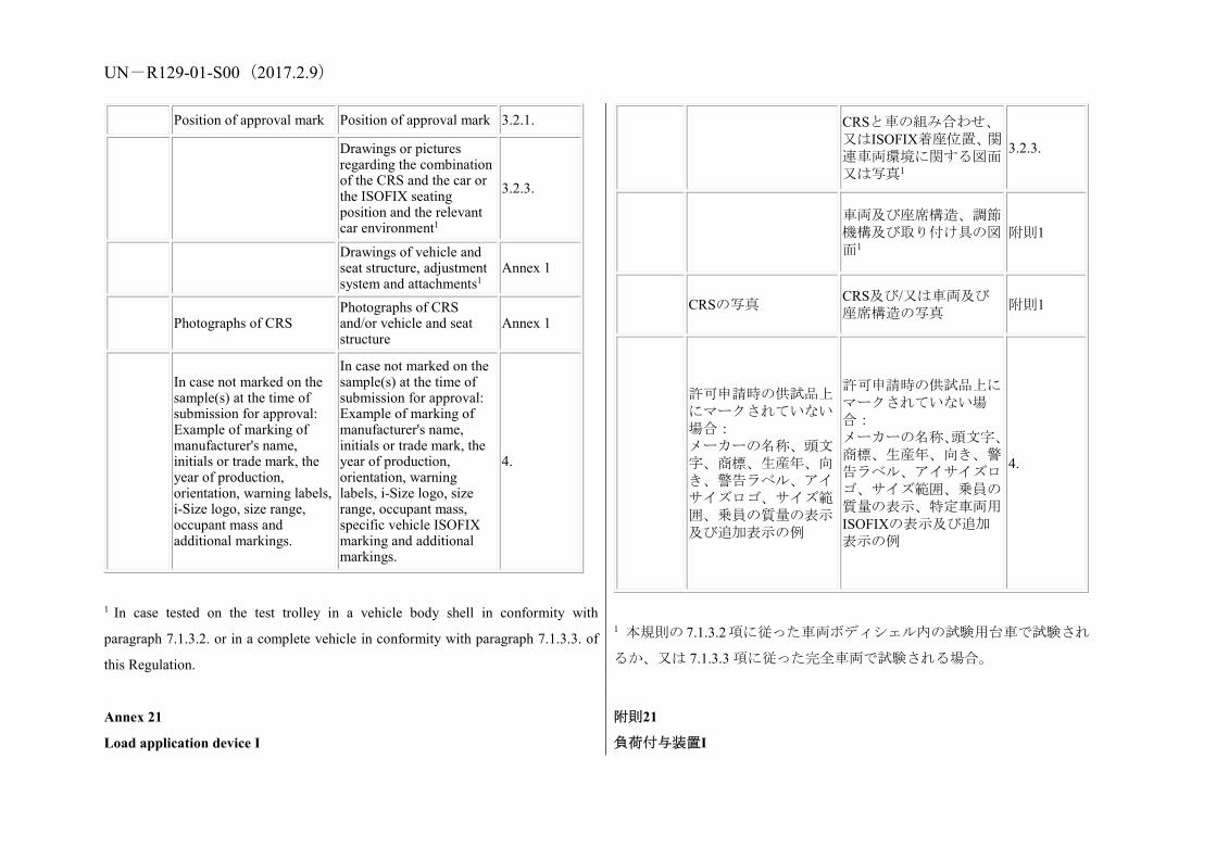
UN-R129-01-S00(2017.2.9) Position of approval mark Position of approval mark 3.2.1.
Drawings or pictures regarding the combination of the CRS and the car or the ISOFIX seating position and the relevant car environment1
3.2.3.
Drawings of vehicle and seat structure, adjustment system and attachments1
Annex 1
Photographs of CRS Photographs of CRS and/or vehicle and seat structure
Annex 1
In case not marked on the sample(s) at the time of submission for approval: Example of marking of manufacturer's name, initials or trade mark, the year of production, orientation, warning labels, i-Size logo, size range, occupant mass and additional markings.
In case not marked on the sample(s) at the time of submission for approval: Example of marking of manufacturer's name, initials or trade mark, the year of production, orientation, warning labels, i-Size logo, size range, occupant mass, specific vehicle ISOFIX marking and additional markings.
4.
1 In case tested on the test trolley in a vehicle body shell in conformity with
paragraph 7.1.3.2. or in a complete vehicle in conformity with paragraph 7.1.3.3. of
this Regulation.
CRSと車の組み合わせ、又はISOFIX着座位置、関連車両環境に関する図面又は写真1
3.2.3.
車両及び座席構造、調節機構及び取り付け具の図面1
附則1
CRSの写真 CRS及び/又は車両及び座席構造の写真 附則1
許可申請時の供試品上にマークされていない場合: メーカーの名称、頭文字、商標、生産年、向き、警告ラベル、アイサイズロゴ、サイズ範囲、乗員の質量の表示及び追加表示の例
許可申請時の供試品上にマークされていない場合: メーカーの名称、頭文字、商標、生産年、向き、警告ラベル、アイサイズロゴ、サイズ範囲、乗員の質量の表示、特定車両用ISOFIXの表示及び追加表示の例
4.
1 本規則の 7.1.3.2項に従った車両ボディシェル内の試験用台車で試験され
るか、又は 7.1.3.3 項に従った完全車両で試験される場合。
Annex 21
Load application device I
附則21
負荷付与装置I

UN-R129-01-S00(2017.2.9)
C 詳細
縮尺 1:1
オフセットセクション図
オフセットセクション図
正面図
縮尺 1:2

UN-R129-01-S00(2017.2.9)
No.
Part Number Name Information Quantity
1 PV000009.1 Head belt – 39 mm - 1
2 PV000009.2
Shoulder belt lh-rh – 39 mm - 2
3 PV000009.3
Crotch belt – 39 mm - 1
4 PV000009.4 Hip belt – 39 mm - 1
5 102 18 31
Stitch pattern (30 x 17)
Stich: 77, thread: 30, colour: SABA grey 8
6 PV000009.5 Plastic buckle 2
7 PV000009.6
Stitch pattern (2 x 37)
Stich: 77, thread: 30, colour: SABA grey 2
No. 部品番号 名称 情報 数量
1 PV000009.1
ヘッドベルト – 39 mm - 1
2 PV000009.2
ショルダーベルトlh-rh – 39 mm - 2
3 PV000009.3
クロッチベルト – 39 mm - 1
4 PV000009.4
ヒップベルト – 39 mm - 1
5 102 18 31
ステッチパターン(30 x 17)
ステッチ:77、糸:30、色:SABAグレー 8
6 PV000009.5
プラスチックバックル 2
7 PV000009.6
ステッチパターン(2 x 37)
ステッチ:77、糸:30、色:SABAグレー 2
Strech
lenght (+/- 5 mm)
Dummy Q
0 Q 1 Q 1,5 Q 3 Q 6 Q 10
Head belt
1 000 mm
1 000
mm
1 000
mm
1 200
mm
1 200
mm
1 200
mm
Shoulder
belt 750 mm 850 mm
950
mm
1 000
mm
1 100
mm
1 300
mm
Crotch belt
300 mm 350 mm
400
mm
400
mm
450
mm
570
mm
Hip belt
400 mm 500 mm
550
mm
600
mm
700
mm
800
mm
ストレッチの
長さ
(+/- 5
mm)
ダミー Q
0 Q 1 Q 1.5 Q 3 Q 6 Q 10
ヘッドベルト
1,000 mm
1,000
mm
1,000
mm
1,200
mm
1,200
mm
1,200
mm
ショルダーベ
ルト 750 mm
850
mm
950
mm
1,000
mm
1,100
mm
1,300
mm
クロッチベル
ト 300 mm
350
mm
400
mm
400
mm
450
mm
570
mm
ヒップベルト
400 mm
500
mm
550
mm
600
mm
700
mm
800
mm

UN-R129-01-S00(2017.2.9)
Dimension
X 120 mm 130 mm
140
mm
140
mm
150
mm 160mm
寸法 X
120 mm
130
mm
140
mm
140
mm
150
mm 160mm
Belt
Width Thickness Expansion Fastness
39 mm +/- 1 mm 1 mm +/- 0,1 mm 5,5 – 6,5 % Min. 15 000 N
ベルト
幅 厚さ 伸長 固定
39 mm +/- 1 mm 1 mm +/- 0.1 mm 5.5 – 6.5 % 最小 15,000 N
all belt radius = 5 mm
Stich pattern Min. required force
12 x 12 mm 3,5 kN
30 x 12 mm 5,3 kN
30 x 17 mm 5,3 kN
30 x 30 mm 7,0 kN
ステッチパターン 要求される最小の力
12 x 12 mm 3.5 kN
30 x 12 mm 5.3 kN
30 x 17 mm 5.3 kN
30 x 30 mm 7.0 kN
全ベルト半径=5 mm
Load application device II 負荷付与装置I
上面図 縮尺 1:2
等角図 縮尺 1:10

UN-R129-01-S00(2017.2.9)
No. Name Information Quantity
1 Main belt – 39 mm - 1 2 Hip belt (upper/lower)– 39 mm - 2 3 Stitch pattern (30 x 17) Stich: 77, thread: 30- 4
No. 名称 情報 数量
1 主ベルト – 39 mm - 1 2 ヒップベルト(上部/下部)–
39 mm - 2 3 ステッチパターン(30 x 17) ステッチ:77、糸:30- 4
Strech lenght
(+/- 5
mm)
Q 0 Q 1 Q 1,5 Q 3 Q 6 Q 10
Main belt (A) 1 740 1 850 1 900 2 000 2 000 2 100
ストレッチの
長さ
(+/- 5
mm)
Q 0 Q 1 Q 1.5 Q 3 Q 6 Q 10
主ベルト(A) 1,740 mm 1,850 1,900 2,000 2,000 2,100

UN-R129-01-S00(2017.2.9)
mm mm mm mm mm mm
Hip belt (B) 530
mm
560
mm
600
mm
630
mm
660
mm
700
mm
Lower
dimension (C)
125
mm
150
mm
150
mm
170
mm
200
mm
200
mm
Mid dimension
(D)
270
mm
300
mm
350
mm
380
mm
380
mm
400
mm
mm mm mm mm mm
ヒップベルト
(B) 530 mm
560
mm
600
mm
630
mm
660
mm
700
mm
下部寸法(C)
125 mm
150
mm
150
mm
170
mm
200
mm
200
mm
中 間 部 寸 法
(D) 270 mm
300
mm
350
mm
380
mm
380
mm
400
mm
Belt
Width Thickness Expansion Fastness
39 mm +/- 1 mm 1 mm +/- 0,1 mm 5,5 – 6,5 % Min. 15 000 N
ベルト
幅 厚さ 伸長 固定
39 mm +/- 1 mm 1 mm +/- 0.1 mm 5.5 – 6.5 % 最小 1,5000 N
Stich pattern Min. required force
12 x 12 mm 3,5 kN
30 x 12 mm 5,3 kN
30 x 17 mm 5,3 kN
30 x 30 mm 7,0 kN
all belt radius = 5 mm
ステッチパターン 要求される最小の力
12 x 12 mm 3.5 kN
30 x 12 mm 5.3 kN
30 x 17 mm 5.3 kN
30 x 30 mm 7.0 kN
全ベルト半径=5 mm
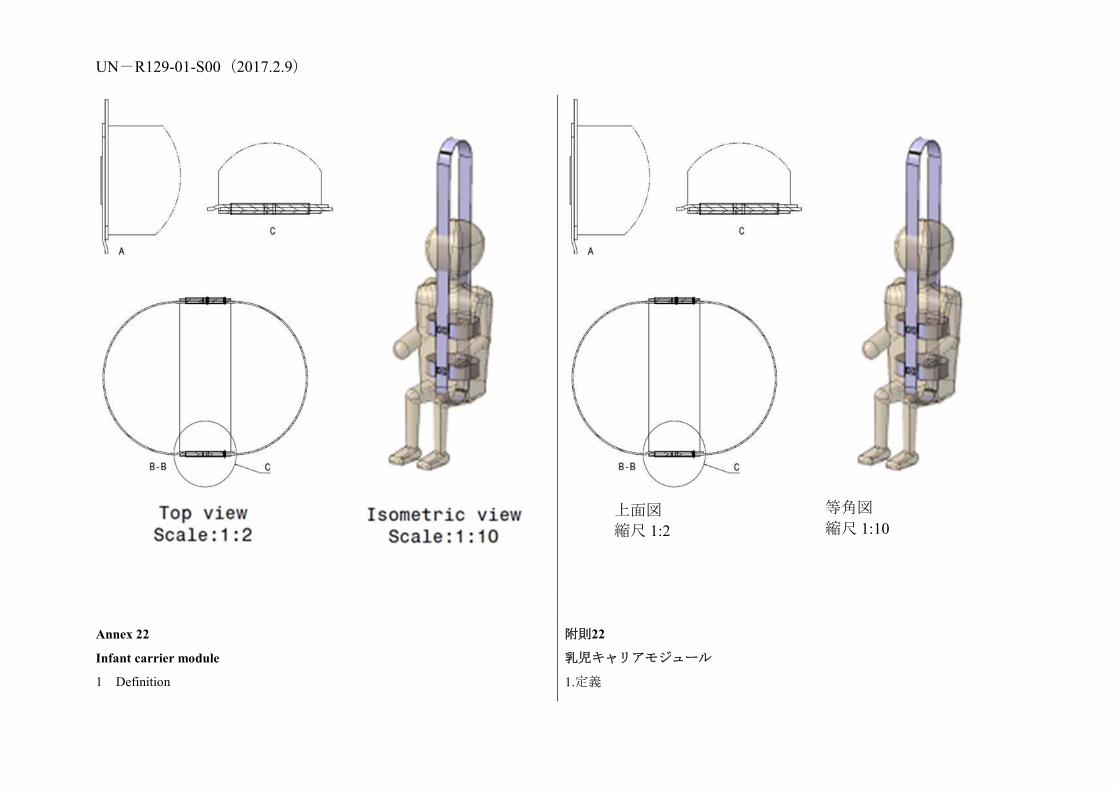
UN-R129-01-S00(2017.2.9)
Annex 22
Infant carrier module
附則22
乳児キャリアモジュール
1 Definition 1.定義
上面図 縮尺 1:2
等角図 縮尺 1:10

UN-R129-01-S00(2017.2.9) "Infant carrier module" means a module that is part of an Integral Enhanced Child
Restraint System restraining a child up to 15 months old and up to 13 kg and which
can be used as a stand alone Child Restraint System. It is designed to be removed
from the vehicle with the child inside and without opening any harness and to carry it
outside of the vehicle.
2. Provisions applied to the infant carrier module
2.1. Belt routing shall comply with paragraphs 4.3. and 6.1.9. of
Regulation No. 44.
2.2. Frontal impact test shall comply with paragraph 7.1.4. of
Regulation No. 44.
2.3. Rear impact test shall comply with paragraph 7.1.4. of Regulation
No. 44.
2.4.Overturning test shall comply with paragraph 7.1.3. of Regulation No. 44."
2.5 For Infant carrier module the following label shall be clearly visible on the
exterior of the packing:
Notice
This is an Enhanced Infant Carrier Module to be used in combination with i-size
product approved according to Regulation No. 129, for use in, "i-Size compatible"
vehicle seating positions as indicated by vehicle manufacturers in the vehicle
user’s manual. This module could also be used as a stand-alone infant carrier
according to the instructions of the Enhanced Child Restraint System
manufacturer.
If in doubt, consult either the manufacturer or the retailer of the Enhanced Child
「乳児キャリアモジュール」とは、年齢 15 ヶ月までおよび 13
kg までの幼児を拘束し、単体の年少者用補助乗車装置として
使用できる一体型の改良型年少者用補助乗車装置の一部を成
すモジュールを指す。これは、幼児が中にいる状態のままハ
ーネスを外さずに車両から取り外し、車両外に運び出すこと
ができるように設計されている。
2. 乳児キャリアモジュールに適用される規定
2.1.ベルトの通し方は、規則 No. 44 の 4.3 項および 6.1.9 項に
適合するものとする。
2.2.前面衝突テストは、規則 No. 44 の 7.1.4 項に適合するもの
とする。
2.3.後面衝突テストは、規則 No. 44 の 7.1.4 項に適合するもの
とする。
2.4.転覆テストは、規則No. 44の7.1.3項に適合するものとする。
2.5. 乳児キャリアモジュールの場合、下記のラベルが梱包の外面において
明確に視認できるものとする
ご案内
本製品は、車両メーカーによって車両ユーザーマニュアルに表示されて
いる「アイサイズ適合」車両着席位置で使用するものとして規則No. 129
に従って認可されたアイサイズ製品と組み合わせて使用するための改
良型乳児キャリアモジュールです。本モジュールは、改良型幼児拘束装
置メーカーの指示に従って独立型乳児キャリアとしても使用できます。

UN-R129-01-S00(2017.2.9)
Restraint System.
ご不明な点がございましたら、改良型幼児拘束装置のメーカーまたは販
売店にお問い合わせください。