umts-fdd band Ⅱ (part 24e) - fccid.io · umts-fdd band Ⅱ (part 24e) band ii ... fundamental...
TRANSCRIPT

Test Report
No.
17070488-FCC-R1
Page 46 of 89
UMTS-FDD Band Ⅱ (Part 24E)
Band II - Low Channel-1 Band II - Low Channel-2
Band II - Middle Channel-1 Band II - Middle Channel-2
Band II - High Channel-1 Band II - High Channel-2
Fundamental
Fundamental
Fundamental

Test Report
No.
17070488-FCC-R1
Page 47 of 89
HSDPA:
UMTS-FDD Band Ⅴ (Part 22H)
Band V - Low Channel-1 Band V - Low Channel-2
Band V - Middle Channel-1 Band V - Middle Channel-2
Band V - High Channel-1 Band V - High Channel-2
Fundamental
Fundamental
Fundamental

Test Report
No.
17070488-FCC-R1
Page 48 of 89
UMTS-FDD Band Ⅱ (Part 24E)
Band II - Low Channel-1 Band II - Low Channel-2
Band II - Middle Channel-1 Band II - Middle Channel-2
Band II - High Channel-1 Band II - High Channel-2
Fundamental
Fundamental
Fundamental

Test Report
No.
17070488-FCC-R1
Page 49 of 89
HSUPA:
UMTS-FDD Band Ⅴ (Part 22H)
Band V - Low Channel-1 Band V - Low Channel-2
Band V - Middle Channel-1 Band V - Middle Channel-2
Band V - High Channel-1 Band V - High Channel-2
Fundamental
Fundamental
Fundamental

Test Report
No.
17070488-FCC-R1
Page 50 of 89
UMTS-FDD Band Ⅱ (Part 24E)
Band II - Low Channel-1 Band II - Low Channel-2
Band II - Middle Channel-1 Band II - Middle Channel-2
Band II - High Channel-1 Band II - High Channel-2
Fundamental
Fundamental
Fundamental
Test Report
No.
17070488-FCC-R1
Page 51 of 89
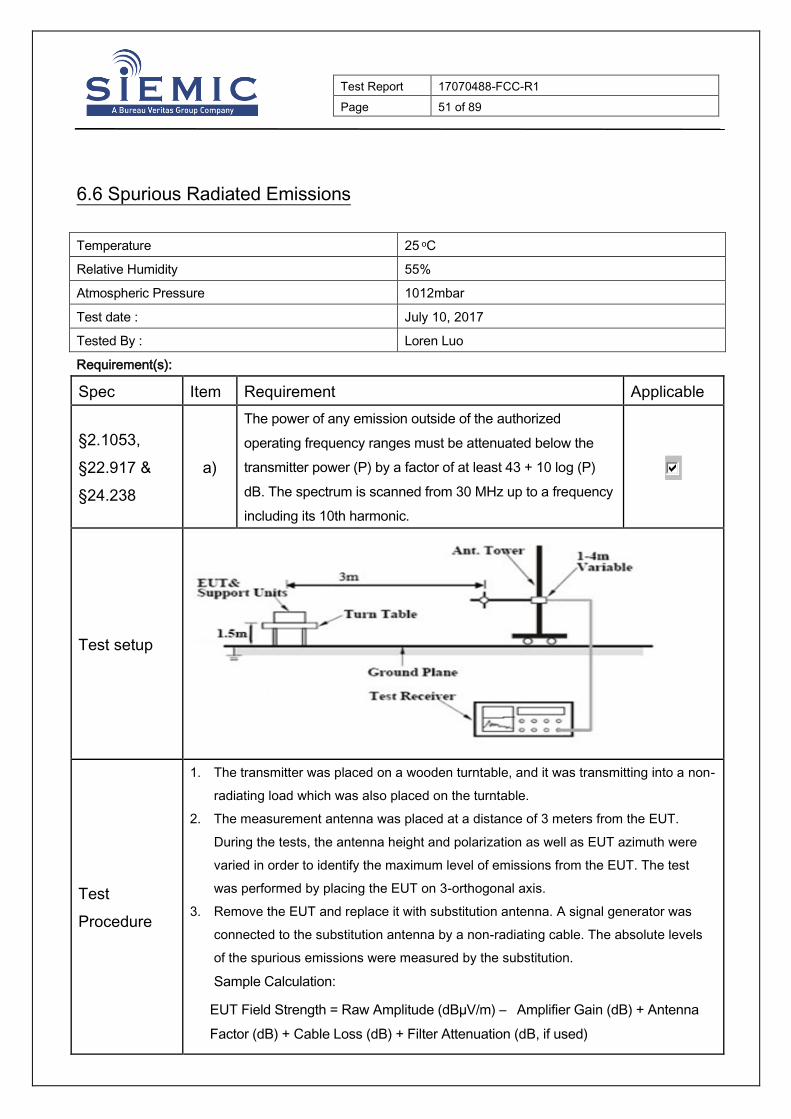
6.6 Spurious Radiated Emissions
Temperature 25 oC
Relative Humidity 55%
Atmospheric Pressure 1012mbar
Test date : July 10, 2017
Tested By : Loren Luo
Requirement(s):
Spec Item Requirement Applicable
§2.1053,
§22.917 &
§24.238
a)
The power of any emission outside of the authorized
operating frequency ranges must be attenuated below the
transmitter power (P) by a factor of at least 43 + 10 log (P)
dB. The spectrum is scanned from 30 MHz up to a frequency
including its 10th harmonic.
Test setup
Test
Procedure
1. The transmitter was placed on a wooden turntable, and it was transmitting into a non-
radiating load which was also placed on the turntable.
2. The measurement antenna was placed at a distance of 3 meters from the EUT.
During the tests, the antenna height and polarization as well as EUT azimuth were
varied in order to identify the maximum level of emissions from the EUT. The test
was performed by placing the EUT on 3-orthogonal axis.
3. Remove the EUT and replace it with substitution antenna. A signal generator was
connected to the substitution antenna by a non-radiating cable. The absolute levels
of the spurious emissions were measured by the substitution.
Sample Calculation:
EUT Field Strength = Raw Amplitude (dBµV/m) – Amplifier Gain (dB) + Antenna
Factor (dB) + Cable Loss (dB) + Filter Attenuation (dB, if used)

Test Report
No.
17070488-FCC-R1
Page 52 of 89
Remark
Result Pass Fail
Test Data Yes N/A
Test Plot Yes (See below) N/A

Test Report
No.
17070488-FCC-R1
Page 53 of 89
Cellular Band (Part 22H) result
Low channel
Frequency
(MHz)
Substituted level
(dBm)
Polarity
(H/V)
Antenna
Gain
Correction (dB)
Cable
Loss
(dB)
Corrected
Reading
(dBm)
Limit
(dBm)
Margin
(dB)
1648.4 -42.63 V 7.95 0.67 -35.35 -13 -22.35
1648.4 -44.05 H 7.95 0.67 -36.77 -13 -23.77
704.9 -52.57 V 6.3 0.4 -46.67 -13 -33.67
602.7 -52.26 H 6.8 0.37 -45.83 -13 -32.83
Middle channel
Frequency
(MHz)
Substituted level
(dBm)
Polarity
(H/V)
Antenna
Gain
Correction (dB)
Cable
Loss
(dB)
Corrected
Reading
(dBm)
Limit
(dBm)
Margin
(dB)
1673.2 -41.91 V 7.95 0.67 -34.63 -13 -21.63
1673.2 -44.09 H 7.95 0.67 -36.81 -13 -23.81
330.7 -53.72 V 6.4 0.26 -47.58 -13 -34.58
611.9 -53.55 H 6.8 0.37 -47.12 -13 -34.12
High channel
Frequency
(MHz)
Substituted level
(dBm)
Polarity
(H/V)
Antenna
Gain
Correction (dB)
Cable
Loss
(dB)
Corrected
Reading
(dBm)
Limit
(dBm)
Margin
(dB)
1697.6 -42.36 V 7.95 0.68 -35.09 -13 -22.09
1697.6 -44.05 H 7.95 0.68 -36.78 -13 -23.78
457.8 -51.02 V 6 0.29 -45.31 -13 -32.31
924.2 -53.36 H 6.2 0.44 -47.6 -13 -34.6
Note:
1, The testing has been conformed to 10*848.8MHz=8,488MHz
2, All other emissions more than 30 dB below the limit
3,GSM voice , GPRS and EGPRS mode were investigated. The results above show only the worse cases
4, X-Axis, Y-Axis and Z-Axis were investigated. The results above show only the worst case.

Test Report
No.
17070488-FCC-R1
Page 54 of 89
PCS Band (Part24E) result
Low channel
Frequency
(MHz)
Substituted level
(dBm)
Polarity
(H/V)
Antenna
Gain
Correction (dB)
Cable
Loss
(dB)
Corrected
Reading
(dBm)
Limit
(dBm)
Margin
(dB)
3700.4 -49.21 V 10.25 1 -39.96 -13 -26.96
3700.4 -49.9 H 10.25 1 -40.65 -13 -27.65
83.1 -53.4 V 0.4 0.12 -53.12 -13 -40.12
600.6 -53.44 H 6.8 0.37 -47.01 -13 -34.01
Middle channel
Frequency
(MHz)
Substituted level
(dBm)
Polarity
(H/V)
Antenna
Gain
Correction (dB)
Cable
Loss
(dB)
Corrected
Reading
(dBm)
Limit
(dBm)
Margin
(dB)
3760 -47.26 V 10.25 1.01 -38.02 -13 -25.02
3760 -50.41 H 10.25 1.01 -41.17 -13 -28.17
329.4 -53.4 V 6.4 0.26 -47.26 -13 -34.26
603.3 -52.99 H 6.8 0.37 -46.56 -13 -33.56
High channel
Frequency
(MHz)
Substituted level
(dBm)
Polarity
(H/V)
Antenna
Gain
Correction (dB)
Cable
Loss
(dB)
Corrected
Reading
(dBm)
Limit
(dBm)
Margin
(dB)
3819.6 -49 V 10.36 1.02 -39.66 -13 -26.66
3819.6 -47.92 H 10.36 1.02 -38.58 -13 -25.58
751.5 -54.71 V 6.4 0.43 -48.74 -13 -35.74
924.5 -51.24 H 6.2 0.44 -45.48 -13 -32.48
Note:
1, The testing has been conformed to 10*1909.8MHz=19,098MHz
2, All other emissions more than 30 dB below the limit
3,GSM voice , GPRS and EGPRS mode were investigated. The results above show only the worse cases
4, X-Axis, Y-Axis and Z-Axis were investigated. The results above show only the worst case.

Test Report
No.
17070488-FCC-R1
Page 55 of 89
UMTS-FDD Band Ⅴ (Part 22H)
Low channel
Frequency
(MHz)
Substituted level
(dBm)
Polarity
(H/V)
Antenna
Gain
Correction (dB)
Cable
Loss
(dB)
Corrected
Reading
(dBm)
Limit
(dBm)
Margin
(dB)
1652.8 -46.49 V 7.95 0.67 -39.21 -13 -26.21
1652.8 -46.56 H 7.95 0.67 -39.28 -13 -26.28
323.9 -51.3 V 6.4 0.26 -45.16 -13 -32.16
599.5 -53.15 H 6.8 0.37 -46.72 -13 -33.72
Middle channel
Frequency
(MHz)
Substituted level
(dBm)
Polarity
(H/V)
Antenna
Gain
Correction (dB)
Cable
Loss
(dB)
Corrected
Reading
(dBm)
Limit
(dBm)
Margin
(dB)
1670 -45.1 V 7.95 0.67 -37.82 -13 -24.82
1670 -47.23 H 7.95 0.67 -39.95 -13 -26.95
785.6 -51.57 V 6.2 0.44 -45.81 -13 -32.81
325.1 -53.37 H 6.4 0.26 -47.23 -13 -34.23
High channel
Frequency
(MHz)
Substituted level
(dBm)
Polarity
(H/V)
Antenna
Gain
Correction (dB)
Cable
Loss
(dB)
Corrected
Reading
(dBm)
Limit
(dBm)
Margin
(dB)
1693.2 -48.29 V 7.95 0.68 -41.02 -13 -28.02
1693.2 -46.92 H 7.95 0.68 -39.65 -13 -26.65
325.6 -53.64 V 6.4 0.26 -47.5 -13 -34.5
601.5 -51.59 H 6.8 0.37 -45.16 -13 -32.16
Note:
1, The testing has been conformed to 10*846.6MHz=8,466MHz
2, All other emissions more than 30 dB below the limit
3,RMC , HSUPA and HSDPA mode were investigated. The results above show only the worse cases
4, X-Axis, Y-Axis and Z-Axis were investigated. The results above show only the worst case.

Test Report
No.
17070488-FCC-R1
Page 56 of 89
UMTS-FDD Band Ⅱ (Part 24E)
Low channel
Frequency
(MHz)
Substituted level
(dBm)
Polarity
(H/V)
Antenna
Gain
Correction (dB)
Cable
Loss
(dB)
Corrected
Reading
(dBm)
Limit
(dBm)
Margin
(dB)
3704.8 -49.7 V 10.25 1 -40.45 -13 -27.45
3704.8 -49.3 H 10.25 1 -40.05 -13 -27.05
328.7 -53.27 V 6.4 0.26 -47.13 -13 -34.13
606.1 -54 H 6.8 0.37 -47.57 -13 -34.57
Middle channel
Frequency
(MHz)
Substituted level
(dBm)
Polarity
(H/V)
Antenna
Gain
Correction (dB)
Cable
Loss
(dB)
Corrected
Reading
(dBm)
Limit
(dBm)
Margin
(dB)
3760 -50.1 V 10.25 1.01 -40.86 -13 -27.86
3760 -50.57 H 10.25 1.01 -41.33 -13 -28.33
507.9 -52.64 V 6.1 0.34 -46.88 -13 -33.88
606.2 -52.68 H 6.8 0.37 -46.25 -13 -33.25
High channel
Frequency
(MHz)
Substituted level
(dBm)
Polarity
(H/V)
Antenna
Gain
Correction (dB)
Cable
Loss
(dB)
Corrected
Reading
(dBm)
Limit
(dBm)
Margin
(dB)
3815.2 -48.92 V 10.36 1.02 -39.58 -13 -26.58
3815.2 -49.84 H 10.36 1.02 -40.5 -13 -27.5
214.4 -54.96 V 3.7 0.18 -51.44 -13 -38.44
865.2 -53.07 H 6.2 0.44 -47.31 -13 -34.31
Note:
1, The testing has been conformed to 10*1907.6MHz=19,076MHz
2, All other emissions more than 30 dB below the limit
3,RMC , HSUPA and HSDPA mode were investigated. The results above show only the worse cases
4, X-Axis, Y-Axis and Z-Axis were investigated. The results above show only the worst case

Test Report
No.
17070488-FCC-R1
Page 57 of 89
6.7 Band Edge
Temperature 25 oC
Relative Humidity 56%
Atmospheric Pressure 1018mbar
Test date : July 09, 2017
Tested By : Loren Luo
Requirement(s):
Spec Item Requirement Applicable
§22.917(a)
§24.238(a) a)
The power of any emission outside of the authorized
operating frequency ranges must be lower than the
transmitter power (P) by a factor of at least 43 + 10 log (P)
dB.
Test setup
Procedure
- The EUT was connected to Spectrum Analyzer and Base Station via
power divider.
- The Band Edges of low and high channels for the highest RF powers
were measured. Setting RBW as roughly BW/100.
Remark
Result Pass Fail
Test Data Yes N/A
Test Plot Yes (See below) N/A
EUT Spectrum Analyzer Base Station

Test Report
No.
17070488-FCC-R1
Page 58 of 89
GSM Voice:
Cellular Band (Part 22H) result
Frequency (MHz) Emission (dBm) Limit (dBm)
823.9975 -16.802 -13
849.0025 -15.682 -13
PCS Band (Part24E) result
Frequency (MHz) Emission (dBm) Limit (dBm)
1849.9975 -19.775 -13
1910.0225 -18.339 -13
GPRS:
Cellular Band (Part 22H) result
Frequency (MHz) Emission (dBm) Limit (dBm)
823.9800 -15.398 -13
849.0200 -16.204 -13
PCS Band (Part24E) result
Frequency (MHz) Emission (dBm) Limit (dBm)
1849.9975 -20.639 -13
1910.0250 -18.569 -13

Test Report
No.
17070488-FCC-R1
Page 59 of 89
EGPRS (MCS 5):
Cellular Band (Part 22H) result
Frequency (MHz) Emission (dBm) Limit (dBm)
823.9989 -15.148 -13
849.0025 -17.058 -13
PCS Band (Part24E) result
Frequency (MHz) Emission (dBm) Limit (dBm)
1849.9975 -19.452 -13
1910.0200 -19.093 -13
RMC:
UMTS-FDD Band Ⅴ (Part 22H)
Frequency (MHz) Emission (dBm) Limit (dBm)
824.000 -24.835 -13
849.275 -25.409 -13
UMTS-FDD Band Ⅱ (Part 24E)
Frequency (MHz) Emission (dBm) Limit (dBm)
1849.925 -23.496 -13
1910.075 -20.987 -13
Test Report
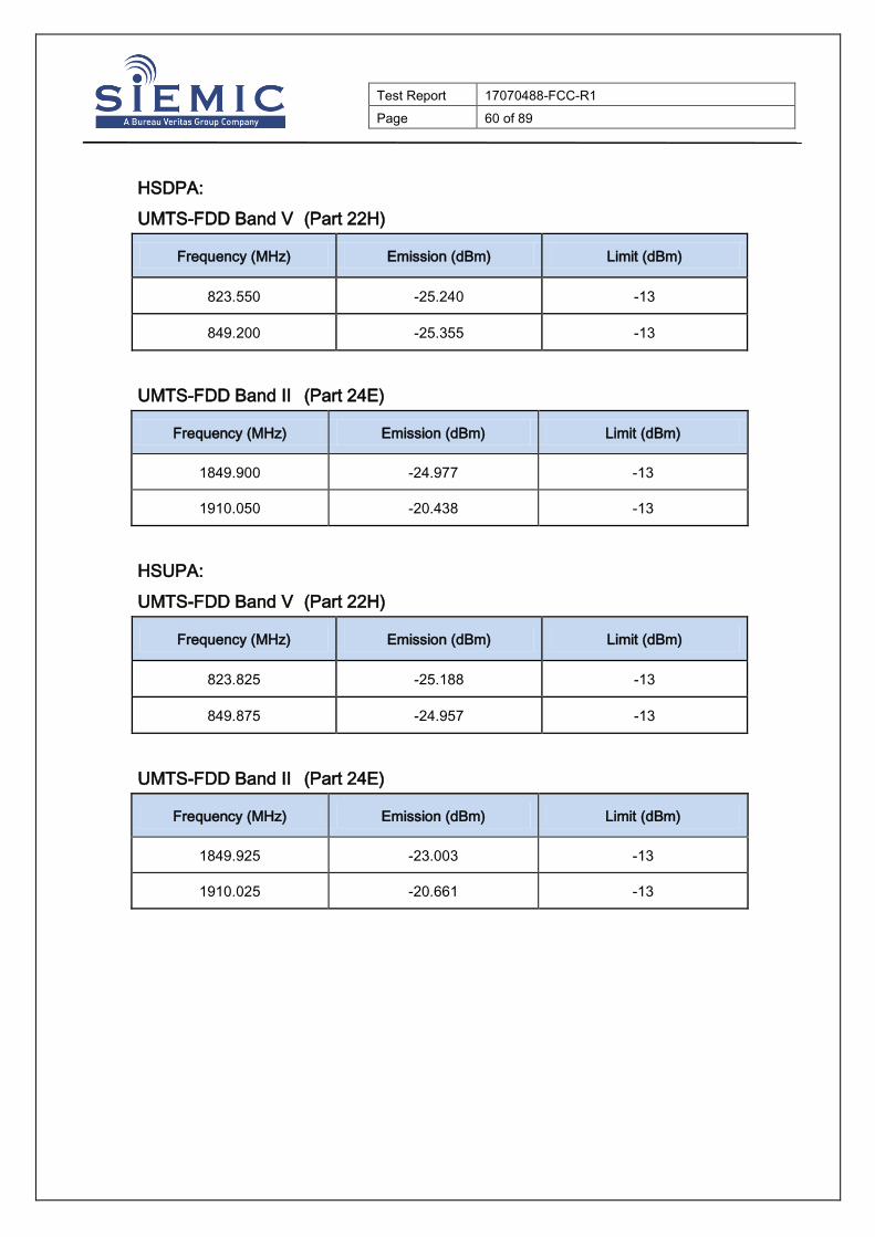
No.
17070488-FCC-R1
Page 60 of 89
HSDPA:
UMTS-FDD Band Ⅴ (Part 22H)
Frequency (MHz) Emission (dBm) Limit (dBm)
823.550 -25.240 -13
849.200 -25.355 -13
UMTS-FDD Band Ⅱ (Part 24E)
Frequency (MHz) Emission (dBm) Limit (dBm)
1849.900 -24.977 -13
1910.050 -20.438 -13
HSUPA:
UMTS-FDD Band Ⅴ (Part 22H)
Frequency (MHz) Emission (dBm) Limit (dBm)
823.825 -25.188 -13
849.875 -24.957 -13
UMTS-FDD Band Ⅱ (Part 24E)
Frequency (MHz) Emission (dBm) Limit (dBm)
1849.925 -23.003 -13
1910.025 -20.661 -13

Test Report
No.
17070488-FCC-R1
Page 61 of 89
GSM Voice:
Test Plots
Cellular Band - Low Channel Cellular Band - High Channel
Note: Offset=Cable loss (4.0) + 10log
(3.16/3)=4.0+0.2=4.2dB
Note: Offset=Cable loss (4.0) + 10log
(3.09/3)=4.0+0.2=4.2dB
PCS Band - Low Channel PCS Band - High Channel
Note: Offset=Cable loss (4.0) + 10log
(3.17/3)=4.5+0.2=4.7dB
Note: Offset=Cable loss (4.0) + 10log
(3.19/3)=4.5+0.3=4.8dB

Test Report
No.
17070488-FCC-R1
Page 62 of 89
GPRS:
Test Plots
Cellular Band - Low Channel Cellular Band - High Channel
Note: Offset=Cable loss (4.0) + 10log
(3.13/3)=4.0+0.2=4.2dB
Note: Offset=Cable loss (4.0) + 10log
(3.13/3)=4.0+0.2=4.2dB
PCS Band - Low Channel PCS Band - High Channel
Note: Offset=Cable loss (4.5) + 10log
(3.14/3)=4.5+0.2=4.7dB
Note: Offset=Cable loss (4.5) + 10log
(3.21/3)=4.5+0.3=4.8dB

Test Report
No.
17070488-FCC-R1
Page 63 of 89
EGPRS (MCS 1):
Test Plots
Cellular Band - Low Channel Cellular Band - High Channel
Note: Offset=Cable loss (4.0) + 10log
(3.11/3)=4.0+0.2=4.2dB
Note: Offset=Cable loss (4.0) + 10log
(3.13/3)=4.0+0.2=4.2dB
PCS Band - Low Channel PCS Band - High Channel
Note: Offset=Cable loss (4.5) + 10log
(3.11/3)=4.5+0.2=4.7dB
Note: Offset=Cable loss (4.5) + 10log
(3.12/3)=4.5+0.2=4.7dB

Test Report
No.
17070488-FCC-R1
Page 64 of 89
RMC:
UMTS-FDD Band Ⅴ - Low Channel UMTS-FDD Band Ⅴ - High Channel
Note: Offset=Cable loss (4.0) + 10log
(46.58/30)=4.0+1.9=5.9 dB
Note: Offset=Cable loss (4.0) + 10log
(46.65/30)=4.0+1.9=5.9 dB
UMTS-FDD Band Ⅱ - Low Channel UMTS-FDD Band Ⅱ - High Channel
Note: Offset=Cable loss (4.5) + 10log
(46.56/30)=4.5+1.9=6.4 dB
Note: Offset=Cable loss (4.5) + 10log
(47.37/30)=4.5+2.0=6.5 dB

Test Report
No.
17070488-FCC-R1
Page 65 of 89
HSDPA:
UMTS-FDD Band Ⅴ - Low Channel UMTS-FDD Band Ⅴ - High Channel
Note: Offset=Cable loss (4.0) + 10log
(46.70/30)=4.0+1.9=5.9 dB
Note: Offset=Cable loss (4.0) + 10log
(46.71/30)=4.0+1.9=5.9 dB
UMTS-FDD Band Ⅱ - Low Channel UMTS-FDD Band Ⅱ - High Channel
Note: Offset=Cable loss (4.5) + 10log
(46.37/30)=4.5+1.9=6.4 dB
Note: Offset=Cable loss (4.5) + 10log
(47.70/30)=4.5+2.0=6.5 dB

Test Report
No.
17070488-FCC-R1
Page 66 of 89
HSUPA:
UMTS-FDD Band Ⅴ - Low Channel UMTS-FDD Band Ⅴ - High Channel
Note: Offset=Cable loss (4.0) + 10log
(46.75/30)=4.0+1.9=5.9 dB
Note: Offset=Cable loss (4.0) + 10log
(46.58/30)=4.0+1.9=5.9 dB
UMTS-FDD Band Ⅱ - Low Channel UMTS-FDD Band Ⅱ - High Channel
Note: Offset=Cable loss (4.5) + 10log
(46.75/30)=4.5+1.9=6.4 dB
Note: Offset=Cable loss (4.5) + 10log
(47.40/30)=4.5+2.0=6.5 dB

Test Report
No.
17070488-FCC-R1
Page 67 of 89
6.8 Frequency Stability
Temperature 25 oC
Relative Humidity 55%
Atmospheric Pressure 1012mbar
Test date : July 10, 2017
Tested By : Loren Luo
Requirement(s):
Spec Item Requirement Applicable
§2.1055,
§22.355 &
§24.235
a)
According to §22.355, the carrier frequency of each transmitter in
the Public Mobile Services must be maintained within the
tolerances given in Table below:
Frequency Tolerance for Transmitters in the Public Mobile
Services
According to §24.235, the frequency stability shall be sufficient to
ensure that the fundamental emissions stay within the authorized
frequency block.
Frequency
Range
(MHz)
Base,
fixed
(ppm)
Mobile ≤ 3
watts
( m)
Mobile ≤ 3
watts
(ppm)
25 to 50 20.0 20.0 50.0
50 to 450 5.0 5.0 50.0
45 to 512 2.5 5.0 50.0
821 to 896 1.5 2.5 2.5
928 to 929 5.0 N/A N/A
929 to 960. 1.5 N/A N/A
2110 to 2220 10.0 N/A N/A
Test setup
EUT Base Station
Thermal Chamber

Test Report
No.
17070488-FCC-R1
Page 68 of 89
Procedure
A communication link was established between EUT and base station. The
frequency error was monitored and measured by base station under variation
of ambient temperature and variation of primary supply voltage.
Limit: The frequency stability of the transmitter shall be maintained within
±0.00025% (±2.5ppm) of the center frequency.
Remark
Result Pass Fail
Test Data Yes N/A
Test Plot Yes (See below) N/A

Test Report
No.
17070488-FCC-R1
Page 69 of 89
GSM Voice:
Cellular Band (Part 22H) result
Middle Channel, fo = 836.6 MHz
Temperature
(℃)
Power Supplied
(VDC)
Frequency
Error
(Hz)
Frequency
Error
(ppm)
Limit
(ppm)
-10
3.7
17 0.0203 2.5
0 18 0.0215 2.5
10 20 0.0239 2.5
20 16 0.0191 2.5
30 14 0.0167 2.5
40 18 0.0215 2.5
50 10 0.0120 2.5
55 16 0.0191 2.5
25 4.2 19 0.0227 2.5
3.5 15 0.0179 2.5
PCS Band (Part 24E) result
Middle Channel, fo = 1880 MHz
Temperature
(℃)
Power Supplied
(VDC)
Frequency
Error
(Hz)
Frequency
Error
(ppm)
Limit
(ppm)
-10
3.7
18 0.0096 2.5
0 9 0.0048 2.5
10 12 0.0064 2.5
20 17 0.0090 2.5
30 12 0.0064 2.5
40 17 0.0090 2.5
50 20 0.0106 2.5
55 15 0.0080 2.5
25 4.2 9 0.0048 2.5
3.5 13 0.0069 2.5

Test Report
No.
17070488-FCC-R1
Page 70 of 89
RMC:
UMTS-FDD Band Ⅴ (Part 22H)
Middle Channel, fo = 835 MHz
Temperature
(℃)
Power Supplied
(VDC)
Frequency
Error
(Hz)
Frequency
Error
(ppm)
Limit
(ppm)
-10
3.7
14 0.0168 2.5
0 20 0.0240 2.5
10 9 0.0108 2.5
20 12 0.0144 2.5
30 9 0.0108 2.5
40 14 0.0168 2.5
50 20 0.0240 2.5
55 16 0.0192 2.5
25 4.2 17 0.0204 2.5
3.5 10 0.0120 2.5
UMTS-FDD Band Ⅱ (Part 24E)
Middle Channel, fo = 1880 MHz
Temperature
(℃)
Power Supplied
(VDC)
Frequency
Error
(Hz)
Frequency
Error
(ppm)
Limit
(ppm)
-10
3.7
18 0.0096 2.5
0 14 0.0074 2.5
10 14 0.0074 2.5
20 19 0.0101 2.5
30 9 0.0048 2.5
40 20 0.0106 2.5
50 11 0.0059 2.5
55 20 0.0106 2.5
25 4.2 9 0.0048 2.5
3.5 16 0.0085 2.5
Test Report
No.
17070488-FCC-R1
Page 71 of 89
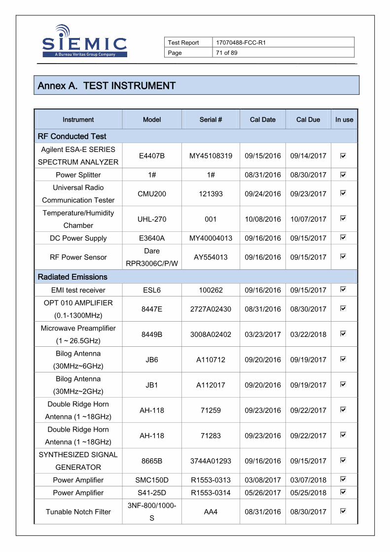
Annex A. TEST INSTRUMENT
Instrument Model Serial # Cal Date Cal Due In use
RF Conducted Test
Agilent ESA-E SERIES
SPECTRUM ANALYZER E4407B MY45108319 09/15/2016 09/14/2017
Power Splitter 1# 1# 08/31/2016 08/30/2017
Universal Radio
Communication Tester CMU200 121393 09/24/2016 09/23/2017
Temperature/Humidity
Chamber UHL-270 001 10/08/2016 10/07/2017
DC Power Supply E3640A MY40004013 09/16/2016 09/15/2017
RF Power Sensor Dare
RPR3006C/P/W AY554013 09/16/2016 09/15/2017
Radiated Emissions
EMI test receiver ESL6 100262 09/16/2016 09/15/2017
OPT 010 AMPLIFIER
(0.1-1300MHz) 8447E 2727A02430 08/31/2016 08/30/2017
Microwave Preamplifier
(1~26.5GHz) 8449B 3008A02402 03/23/2017 03/22/2018
Bilog Antenna
(30MHz~6GHz) JB6 A110712 09/20/2016 09/19/2017
Bilog Antenna
(30MHz~2GHz) JB1 A112017 09/20/2016 09/19/2017
Double Ridge Horn
Antenna (1 ~18GHz) AH-118 71259 09/23/2016 09/22/2017
Double Ridge Horn
Antenna (1 ~18GHz) AH-118 71283 09/23/2016 09/22/2017
SYNTHESIZED SIGNAL
GENERATOR 8665B 3744A01293 09/16/2016 09/15/2017
Power Amplifier SMC150D R1553-0313 03/08/2017 03/07/2018
Power Amplifier S41-25D R1553-0314 05/26/2017 05/25/2018
Tunable Notch Filter 3NF-800/1000-
S AA4 08/31/2016 08/30/2017

Test Report
No.
17070488-FCC-R1
Page 72 of 89
Tunable Notch Filter 3NF-
1000/2000-S AM 4 08/31/2016 08/30/2017

Test Report
No.
17070488-FCC-R1
Page 73 of 89
Annex B. EUT And Test Setup Photographs
Annex B.i. Photograph: EUT External Photo
Whole Package View
Adapter - Front View

Test Report
No.
17070488-FCC-R1
Page 74 of 89
EUT - Front View
EUT - Rear View

Test Report
No.
17070488-FCC-R1
Page 75 of 89
EUT - Top View
EUT - Bottom View

Test Report
No.
17070488-FCC-R1
Page 76 of 89
EUT - Left View
EUT - Right View

Test Report
No.
17070488-FCC-R1
Page 77 of 89
Annex B.ii. Photograph: EUT Internal Photo
Cover Off - Top View 1
Cover Off - Top View 2

Test Report
No.
17070488-FCC-R1
Page 78 of 89
Battery - Front View
Battery - Rear View
Test Report
No.
17070488-FCC-R1
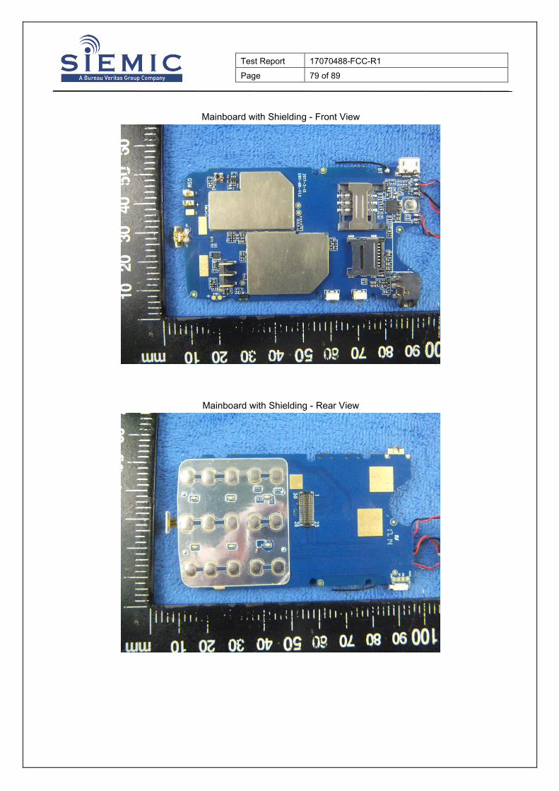
Page 79 of 89
Mainboard with Shielding - Front View
Mainboard with Shielding - Rear View

Test Report
No.
17070488-FCC-R1
Page 80 of 89
Mainboard without Shielding - Front View
Mainboard without Shielding - Rear View

Test Report
No.
17070488-FCC-R1
Page 81 of 89
Small Mainboard - Front View
Small Mainboard - Rear View

Test Report
No.
17070488-FCC-R1
Page 82 of 89
LCD – Front View
LCD – Rear View

Test Report
No.
17070488-FCC-R1
Page 83 of 89
GSM/PCS/UMTS - Antenna View
BT - Antenna View

Test Report
No.
17070488-FCC-R1
Page 84 of 89
Annex B.iii. Photograph: Test Setup Photo
Radiated Spurious Emissions Test Setup Below 1GHz Radiated Spurious Emissions Test Setup Above
1GHz

Test Report
No.
17070488-FCC-R1
Page 85 of 89
Annex C. TEST SETUP AND SUPPORTING EQUIPMENT
Annex C.ii. TEST SET UP BLOCK
Block Configuration Diagram for Radiated Emissions
Receiving Antenna
Support Equipment
Antenna
150 cm above
ground plane
Test Table
d=3meter
EUT Adapter
Headset

Test Report
No.
17070488-FCC-R1
Page 86 of 89
Annex C. iI. SUPPORTING EQUIPMENT DESCRIPTION
The following is a description of supporting equipment and details of cables used with the EUT.
Supporting Equipment:
Manufacturer Equipment
Description Model Serial No
Jethro Trading LTD. Adapter HJ-050050-US N/A
SAMSUNG headset HS330 N/A
Agilent Wireless Connectivity
Test Set N4010A N/A
OEM omnidirectional an
tenna AntSuck N/A
Supporting Cable:
Cable type Shield Type Ferrite
Core Length Serial No
USB Cable Un-shielding No 0.8m N/A

Test Report
No.
17070488-FCC-R1
Page 87 of 89
Annex C.ii. EUT OPERATING CONKITIONS
N/A

Test Report
No.
17070488-FCC-R1
Page 88 of 89
Annex D. User Manual / Block Diagram / Schematics / Partlist
Please see the attachment

Test Report
No.
17070488-FCC-R1
Page 89 of 89
Annex E. DECLARATION OF SIMILARITY
N/A