ultrastructural changes in axons following exposure to pulsed radiofrequency fields
DESCRIPTION
A-deltaandA-betafibers.Theresultsarediscussedinterms of internal electric field strengths and thermodynamic parameters. INTRODUCTION Addresscorrespondenceandreprintrequeststo:EricR.CosmanJr., PhD,872ConcordAvenue,Belmont,MA02478,U.S.A.E-mail:ercosman@ mit.edu. Submitted:June29,2009;Accepted:July18,2009 DOI.10.1111/j.1533-2500.2009.00317.x Key Words: pulsed radiofrequency, PRF, sensory axon, electronmicroscopy,microtubules,mitochondria papr_317 407..417TRANSCRIPT

papr_317 407..417
ORIGINAL ARTICLE
Ultrastructural Changes in AxonsFollowing Exposure to Pulsed
Radiofrequency Fields
Serdar Erdine, MD*; Ayhan Bilir, MD†; Eric R. Cosman Sr., PhD§;Eric R. Cosman Jr., PhD¶
*Department of Algology, Istanbul Faculty of Medicine, Istanbul University, Capa Kinikleri,Cerrahi Monoblok, Istanbul; †Department of Histology and Embryology, Faculty of
Medicine, Istanbul University, Cap, Istanbul, Turkey; §Department of Physics, MassachusettsInstitute of Technology, Cambridge, Massachusetts; ¶Cosman Medical, Inc., Burlington,
Massachusetts, U.S.A.
� Abstract: Pulsed radiofrequency (PRF) fields applied byan electrode to neural structures, such as the peripheralsensory nociceptor axons and dorsal root ganglion, are clini-cally effective in reducing pain and other neuropathic syn-dromes. However, a full understanding of the underlyingmechanisms by which this occurs has not yet been clarified. Inthis study, PRF is applied to the afferent axons of the sciaticnerves of rats. A standard radiofrequency (RF) electrode andRF generator is used to apply the RF signal output to thesciatic nerve using standard PRF parameters that have beensuccessfully used in clinical practice. The ultrastructure of thetreated axons is observed after 10 days by electron micros-copy. A control, sham application is simultaneously appliedto the contralateral sciatic nerve to provide a statistical dif-ferential comparison. It is found that the internal ultrastruc-tural components of the axons show microscopic damageafter PRF exposure, including: abnormal membranes andmorphology of mitochondria, and disruption and disorgani-zation of microfilaments and microtubules. The damageappears to be more pronounced for C-fibers than for
A-delta and A-beta fibers. The results are discussed in termsof internal electric field strengths and thermodynamicparameters. �
Key Words: pulsed radiofrequency, PRF, sensory axon,electron microscopy, microtubules, mitochondria
INTRODUCTION
The pulsed radiofrequency (PRF) technique has beeneffective in the treatment of numerous pain and neuro-pathic syndromes. Like the classical continuous radiof-requency (CRF) technique, it involves the placement ofa radiofrequency (RF) electrode in proximity to theneural target structure and delivery of an RF signaloutput from an RF generator to that structure. Thedifference is that in CRF, the signal output is typically acontinuous wave of RF voltage (and therefore a con-tinuous wave of RF current), whereas in PRF, the RFwave is broken up into short bursts of signal outputbetween which are time periods of no signal at all. In thetypical CRF technique, the tissue is heated grossly byelectrical energy dissipation, and it is the tissue heatingthat leads to localized destruction of the neural tissueand consequent interruption of neural signaling. Thishas historically been called the RF heat lesion. The
Address correspondence and reprint requests to: Eric R. Cosman Jr.,PhD, 872 Concord Avenue, Belmont, MA 02478, U.S.A. E-mail: [email protected].
Submitted: June 29, 2009; Accepted: July 18, 2009DOI. 10.1111/j.1533-2500.2009.00317.x
© 2009 World Institute of Pain, 1530-7085/09/$15.00Pain Practice, Volume 9, Issue 6, 2009 407–417

typical PRF technique is characterized by much loweraverage temperature elevations of the target tissuebecause of the smaller duty cycle on time of the PRFpulsatory RF output. Indeed, PRF is often effectivewithout raising the average target tissue temperatureabove 42°C, which has been traditionally been thoughtto be below the irreversible tissue destruction threshold(ie, the heat-lesion threshold) of 45°C to 50°C.
Since its discovery,1 it has been speculated that PRF isa modulatory or nondestructive technique. However,this has not been proven, and some evidence to thecontrary has been shown.2,3 The perception that PRF isnondestructive is encouraged by the following factors:(1) PRF can be effective for tissue temperatures belowthe heat-lesion threshold, (2) in most cases, there is nosignificant sensory loss following PRF, and (3) there isoften imperceptible discomfort during a PRF treatment,even near highly sensitive structures such as the dorsalroot ganglion (DRG), for which a CRF treatment can beintolerably painful. On the other hand, it has beenshown by electron microscopy2 that there is significantdisruption of the ultrastructure in the soma of neuronsin the DRG that has been exposed to PRF. Anotherstudy3 has shown that when neurons are subjected to theabnormally high electric fields characteristic of PRF,those neurons are subjected to large transmembranepotentials and localized heat flashes whose temperaturesexceed the heat-lesion threshold; both of these couldhave a destructive effect on the neurons, on either amacroscopic or microscope scale.
In this article, the structural effects of PRF on sensorynociceptive axons are studied using electron micros-copy. It has been reported4 that PRF is clinically effectiveat relieving pain when applied to pure afferent sensorynerves such as the medial branch for the treatment offacet-related pain. An objective of this study is to deter-mine experimentally if there is a physical change in thegross structure or the ultrastructure of axons after PRFthat might account for these clinical observations. Theeffect on axons was chosen rather than the soma of theDRG, because the ultrastructure in the axons is lesscomplex than in the soma, and thus the interpretation ofresults may be clearer. This will potentially enable physi-cal modeling of the interaction of electric forces oncellular structures, which could provide an explanationfor the pain-relieving phenomenon of PRF.3
METHODS AND MATERIALS
The PRF study was performed on the sciatic nerves offive male Wistar Albino rats, weighing 220 to 250 g. All
rats were housed in a quiet and temperature-controlledroom (21 1 3°C), maintained on a 12-hour light/darkcycle (0700 to 1900), and were allowed food and waterad libitum. All procedures were approved by the Experi-mental Animal and Research Ethical Committee. Theanimals were acclimatized to laboratory for at least 1hour before testing, and the experiments were per-formed in accordance with current guidelines for thecare of laboratory animals and ethical guidelines forinvestigations of experimental pain in consciousanimals.5
Surgical Electrode Positioning
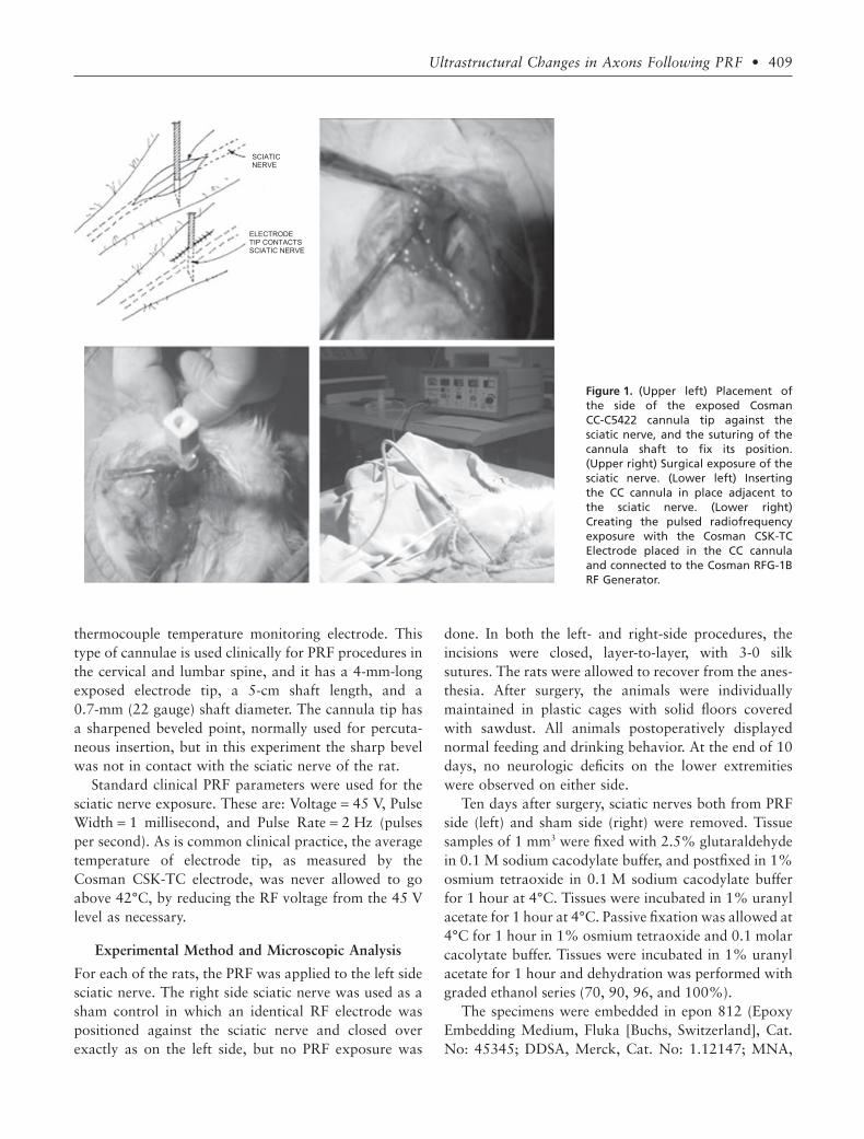
The procedure was performed using ketamine anesthe-sia (35 mg/kg). A surgical incision above the sciaticnerve of minimal length allowed exact positioning of theelectrode tip in contact with the nerve as shown inFigure 1. Once the electrode was positioned, the incisionwas closed tightly around the electrode; this was suffi-cient to stabilize the position of the cannula in the tissueand against the sciatic nerve. The goal was to have thetissue surrounding the nerve and electrode in the sameconfiguration as it would have been if the electrode hadbeen perfectly placed percutaneously, as it is in the clini-cal context. The sharpened portion of the tip of theelectrode was placed deep enough so that only the cylin-drical wall of the electrode was in contact with theepineurium. Therefore, the exposed metal tip of the RFelectrode was positioned so the cylindrical side wall ofthe electrode was in contact with the sciatic nerve, notthe sharpened point or the sharp bevel edges of theelectrode tip. This was done because the electric field atthe cylindrical “side barrel” of the electrode is very welldefined compared to singularities at the sharp edges nearthe bevel point,3 for which the change of field strength asa function from distance for the electrode is very rapidand less definable. Thus, a quantitative analysis of anystructural effects seen in the experimental configurationcan be better interpreted with respect to the magnitudeof the electric fields on the axons of the sciatic nerve.Furthermore, this configuration has been used clinicallyon the medial branch PRF exposures, so that anyobserved effects would be relevant to the question of theorigin of pain relief for PRF.
Radiofrequency Equipment
The RF generator was a Cosman RFG-1B RF Generator(Cosman Medical, Inc., Burlington, MA, USA), and theelectrode system was a standard Cosman CC-C5422 RFcannula into which was inserted a Cosman CSK-TC5
408 • erdine et al.
thermocouple temperature monitoring electrode. Thistype of cannulae is used clinically for PRF procedures inthe cervical and lumbar spine, and it has a 4-mm-longexposed electrode tip, a 5-cm shaft length, and a0.7-mm (22 gauge) shaft diameter. The cannula tip hasa sharpened beveled point, normally used for percuta-neous insertion, but in this experiment the sharp bevelwas not in contact with the sciatic nerve of the rat.
Standard clinical PRF parameters were used for thesciatic nerve exposure. These are: Voltage = 45 V, PulseWidth = 1 millisecond, and Pulse Rate = 2 Hz (pulsesper second). As is common clinical practice, the averagetemperature of electrode tip, as measured by theCosman CSK-TC electrode, was never allowed to goabove 42°C, by reducing the RF voltage from the 45 Vlevel as necessary.
Experimental Method and Microscopic Analysis
For each of the rats, the PRF was applied to the left sidesciatic nerve. The right side sciatic nerve was used as asham control in which an identical RF electrode waspositioned against the sciatic nerve and closed overexactly as on the left side, but no PRF exposure was
done. In both the left- and right-side procedures, theincisions were closed, layer-to-layer, with 3-0 silksutures. The rats were allowed to recover from the anes-thesia. After surgery, the animals were individuallymaintained in plastic cages with solid floors coveredwith sawdust. All animals postoperatively displayednormal feeding and drinking behavior. At the end of 10days, no neurologic deficits on the lower extremitieswere observed on either side.
Ten days after surgery, sciatic nerves both from PRFside (left) and sham side (right) were removed. Tissuesamples of 1 mm3 were fixed with 2.5% glutaraldehydein 0.1 M sodium cacodylate buffer, and postfixed in 1%osmium tetraoxide in 0.1 M sodium cacodylate bufferfor 1 hour at 4°C. Tissues were incubated in 1% uranylacetate for 1 hour at 4°C. Passive fixation was allowed at4°C for 1 hour in 1% osmium tetraoxide and 0.1 molarcacolytate buffer. Tissues were incubated in 1% uranylacetate for 1 hour and dehydration was performed withgraded ethanol series (70, 90, 96, and 100%).
The specimens were embedded in epon 812 (EpoxyEmbedding Medium, Fluka [Buchs, Switzerland], Cat.No: 45345; DDSA, Merck, Cat. No: 1.12147; MNA,
Figure 1. (Upper left) Placement ofthe side of the exposed CosmanCC-C5422 cannula tip against thesciatic nerve, and the suturing of thecannula shaft to fix its position.(Upper right) Surgical exposure of thesciatic nerve. (Lower left) Insertingthe CC cannula in place adjacent tothe sciatic nerve. (Lower right)Creating the pulsed radiofrequencyexposure with the Cosman CSK-TCElectrode placed in the CC cannulaand connected to the Cosman RFG-1BRF Generator.
SCIATIC NERVE
ELECTRODE TIP CONTACTS SCIATIC NERVE
Ultrastructural Changes in Axons Following PRF • 409

Merck, Cat. No: 1.12251; DMP, Merck, Cat. No:12388 [Merck Co., Whitehouse Station, NJ, USA]).Samples were trimmed and sectioned by using LeicaMR 2,145 microtome (Heerbrugg, Switzerland) at 70nanometer thickness and placed on copper grids, stainedby 5% uranyl acetate and Reynold’s lead citrate. Thesamples were then viewed and photographed under aJEM 1,011 transmission electron microscope (JEOL,Tokyo, Japan) at the Istanbul University, Institute forExperimental Medicine.
Sampling of axons from the sections was done atrandom positions across the sciatic nerve. No correla-tion was made in this study between the abnormalitiesobserved and the distance from the axon in question tothe electrode surface, although it is expected that electricfield strength will vary substantially as a function of thatdistance.
RESULTS
The images from the electron microscopic studyrevealed an increased level of ultrastructural damageand disruption in the PRF-exposed axons (left side) ascompared to the sham control axons (right side). Caseexamples from the numerous electron microscopyimages are shown in Figures 2 to 7, and the results aresummarized in Figure 8 and Tables 2 to 5. In thesefigures and tables, the standard classification of neuronsis used. This classification is based on axon diameterand myelination. C-fibers axons have a diameter of 0.5to 2 mm (micrometers) and are unmyelinated. A-deltafiber axons have a diameter of 2 to 5 mm and are myeli-nated. A-beta fibers have a diameter of 5 to 20 mm andare myelinated.
The images are all longitudinal slices because theyshow best any effects on axon membrane, mitochon-dria, and microtubules and microfilaments. The order-ing of the images in Figures 2 to 7 have been selected ina progression of increasing damage and disruption asseen on the PRF-exposed axons and as quantified in thescoring shown in Table 1.
Figure 2 shows a typical electron micrographthrough an axon in the sham control group (right side).The axoplasm contains well-aligned microtubule andmicrofilaments with no obvious abnormalities. Themitochondrion in the figure is well shaped and its mem-branes and crista are normal. This has an example of nodamage, Score 1–, in Table 1.
Figure 3 shows a comparison of C-fiber electronmicrographs from the PRF and the control groups. Thecontrol image on the right has normal microtubule,microfilaments, mitochondria, and axon membrane;Score 1– in Table 1. The image from the PRF group onthe left has relatively normal patterns of microtubulesand microfilaments, but has several distorted andswollen mitochondria that are invested with vacuolesand a cloudy white structure that invades the crista andpossibly the inner and outer membranes of the mito-chondria; this has Score 1+, low damage, from Table 1.In both cases the axonal membrane appears intact andnormal.
Table 1. Scoring of Damage to Axonal Ultrastructure
ScoreDegree ofDamage Description of Damage
1- No damage Mitochondria, microtubules, and microfilaments normal1+ Low damage Some vacuole and inclusions, some swelling in the mitochondria; and microtubule and microfilaments normal2+ Mild damage Large vacuoles, damaged external membrane and crista, formation of multilaminar structures, and swollen shape of
mitochondria; and occasional abnormalities on the microtubules and microfilaments3+ High damage The same as in 2+ (mild damage), but in addition large areas of fragmented microtubules and microfilaments, or
substantial absence of microtubules
Figure 2. An electron micrograph (¥30,000) from the shamcontrol group (right side). The mitochondria (arrow) are intactand without defects, and the microtubules and microfilamentsare also laminar and longitudinally well arranged. This is Score 1–in Table 1.
410 • erdine et al.
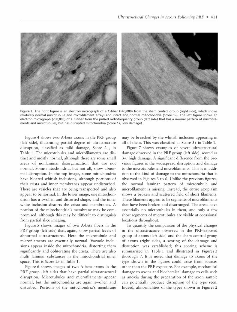
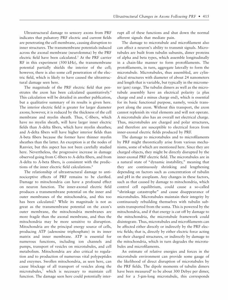
Figure 4 shows two A-beta axons in the PRF group(left side), illustrating partial degree of ultrastructuredisruption, classified as mild damage, Score 2+, inTable 1. The microtubules and microfilaments are dis-tinct and mostly normal, although there are some smallareas of nonlaminar disorganization that are notnormal. Some mitochondria, but not all, show abnor-mal disruption. In the top image, some mitochondriahave bloated whitish inclusions, although portions oftheir crista and inner membranes appear undisturbed.There are vesicles that are being transported and alsoappear to be normal. In the lower image, one mitochon-drion has a swollen and distorted shape, and the innerwhite inclusion distorts the crista and membranes. Aportion of the mitochondria’s membrane may be com-promised, although this may be difficult to distinguishfrom partial slice imaging.
Figure 5 shows images of two A-beta fibers in thePRF group (left side) that, again, show partial levels ofabnormal ultrastructures. Here the microtubule andmicrofilaments are essentially normal. Vacuole inclu-sions appear inside the mitochondria, distorting themsignificantly and obliterating the crista. There are alsomulti laminar substances in the mitochondrial innerspace. This is Score 2+ in Table 1.
Figure 6 shows images of two A-beta axons in thePRF group (left side) that have partial ultrastructuraldisruption. Microtubules and microfilaments appearnormal, but the mitochondria are again swollen anddisturbed. Portions of the mitochondria’s membrane
may be breached by the whitish inclusion appearing inall of them. This was classified as Score 3+ in Table 1.
Figure 7 shows examples of severe ultrastructuraldamage observed in the PRF group (left side), scored as3+, high damage. A significant difference from the pre-vious figures is the widespread disruption and damageto the microtubules and microfilaments. This is in addi-tion to the kind of damage to the mitochondria that isobserved in Figures 3 to 6. Unlike the previous figures,the normal laminar pattern of microtubule andmicrofilament is missing. Instead, the entire axoplasmshows a broken and scattered field of short filaments.These filaments appear to be segments of microfilamentsthat have been broken and disarranged. The areas haveessentially no microtubules in them, and only a fewshort segments of microtubules are visible at occasionallocations throughout.
To quantify the comparison of the physical changesin the ultrastructure observed in the PRF-exposedgroup of axons (left side) and the sham control groupof axons (right side), a scoring of the damage anddisruption was established; this scoring scheme issummarized in Table 1 and illustrated in Figures 2thorough 7. It is noted that damage to axons of thetype shown in the figures could arise from sourcesother than the PRF exposure. For example, mechanicaldamage to axons and biochemical damage to cells suchas anoxia during the preparation of the axon samplecan potentially produce disruption of the type seen.Indeed, abnormalities of the types shown in Figures 2
Figure 3. The right figure is an electron micrograph of a C-fiber (¥40,000) from the sham control group (right side), which showsrelatively normal microtubule and microfilament arrays and intact and normal mitochondria (Score 1–). The left figure shows anelectron micrograph (¥30,000) of a C-fiber from the pulsed radiofrequency group (left side) that has a normal pattern of microfila-ments and microtubules, but has disrupted mitochondria (Score 1+, low damage).
Ultrastructural Changes in Axons Following PRF • 411

to 7 do occur to some degree in the control samples.Thus, the comparison of the PRF group and controlgroup results based on this scoring is important to dif-ferentiate any PRF damages from damage from otherspurious sources.
A number of axons were sampled from each of thePRF group (left side) and the sham control group (rightside) to improve the statistical reliability of the scoringresults. In all, there were 279 axons evaluated in thePRF group, which is the left side and designated as “L”
in the results in Tables 2 and 3 below; and there were265 axons evaluated in the sham control group, which isthe right side and designated as “R” in Tables 4 and 5.
DISCUSSION
The results in Figure 8 and Tables 2 to 5 show a differ-ence in the effect on the PRF group compared to thesham control group. The PRF group shows substantiallymore ultrastructural damage in electron microscopy.The damage appears in only the structural elements
Figure 4. Electron microscopic images (¥40,000) of an A-betaaxons from the PRF group (left side) showing mild damage, Score2+, of Table 1. In both images, abnormalities are not extreme,although there are some present. The microtubules andmicrofilaments are, for the most part, normal with distinct lon-gitudinal directional patterns, with only small regions tending tobe deviant (thin arrow in the top figure). Some of the mitochon-dria, but not all, have abnormal whitish inclusions that invest thecrista and the inner membrane, and are swollen and misshapen(thick arrows).There is some evidence of partial slice imaging,which can account for fading of the membrane definition inplaces.
Figure 5. Electron micrographs (¥40,000) of two separate A-betaaxons in the pulsed radiofrequency group (left side) showingmild damage, Score 2+. In both images, the microtubule andmicrofilament arrays are normal. However, in the upper figure,the left mitochondria are bloated with white inclusions thatinvest the inner structure and possibly also the inner and outermembranes (thin arrow). The rightmost mitochondrion hasdegraded membranes and displays multilaminar substance for-mations (thick arrow). In the lower image, a vacuole is formed inthe abnormally shaped mitochondria (thin arrow), and a multi-laminar substance appears in the other mitochondria (thickarrow).
412 • erdine et al.

within the axons, and no damage was evident to theouter axonal membrane in either group. It is notablehowever, that electron microscopy may not revealmicroscopic changes in the axon membrane such asalteration of ion channels or pumps.
Damage is seen in both the PRF and the controlgroups; however, the relative occurrence of damage ishigher in the PRF group. It is possible that somedamage, such as crushing injury or anoxia, may arise
Figure 6. Electron micrographs of two different A-beta axons(¥40,000) in the PRF group (left side). Several mitochondria areabnormally swollen. White inclusions invade the crista and innerand outer membranes. The membranes appear abnormallydefined and perhaps breached in places (arrows), although thiscould be an artifact of slicing and preparation. The microtubuleand microfilament arrays are unremarkable. This a Score 3+ inTable 1.
Table 2. PRF Group, Left Side (L): Number of Fibers
Damage Score
1- 1+ 2+ 3+
A-beta 30 32 18 12A-delta 28 22 25 16C-fiber 10 18 23 34
PRF, pulsed radiofrequency.
Figure 7. Electron micrographs (¥40,000) of two different A-betaaxons in the PRF group (left side), Score 3+, high damage. In bothpictures the pattern of microtubules and microfilaments is seri-ously disrupted. Significant areas are filled with scattered shortsegments of non-longitudinal microfilament fragments and aredevoid of any microtubules (thin arrows). Occasional microtu-bule fragments are evident (dashed arrows) Mitochondria aredistorted and bloated, vacuoles and inclusions swell their innerspace and crista, and their internal and exterior membranesappear damaged (thick arrows).
Table 3. PRF Group, Left Side (L): Percent of Fibers (%)
Damage Score
1- 1+ 2+ 3+
A-beta 34 36 20 13A-delta 31 24 27 18C-fiber 12 21 27 40
PRF, pulsed radiofrequency.
Ultrastructural Changes in Axons Following PRF • 413

from mechanical extraction and manipulation of thetissue, and the chemical preparation of samples for elec-tron microscopy. However, by the relative comparisonof the PRF vs. the control group, and by recruitment ofa large enough sampling of neurons, these spurioussources of damage can be differentiated from PRFdamage. Indeed, it appears that the PRF damage isstatistically significant over the control group.
There is also a relatively greater degree of damage forsmaller diameter fibers. The C-fibers (diameter 0.5 to
2 mm) show greater damage than the A-delta fibers(diameter 2 to 5 mm), and the A-delta fibers show agreater damage than the A-beta fibers (diameter 5 to20 mm). It is known that the C-fibers and the A-deltafibers are the principal sensory nociceptors, and that theA-beta fibers are primarily related to touch and to non-pain-related sensations. Thus, the preferential effect ofPRF on the C and A-delta fibers may suggest a connec-tion to the pain relieving effect of PRF and its relativesparing of tactile sensory input.
Figure 8. The upper histogram showsthe percent of fibers of each type,within each group, that fall into thescoring categories as defined inTable 1. They are classified by differ-ent fiber diameters and by whetherthey are in the pulsed radiofrequency(PRF) group (L) or the sham group (R).The lower histogram shows theoverall percentage of undamaged (1–)vs. damaged (1+, 2+, and 3+) fibersin each of the fiber types based onthe damage score criteria of Table 1.A-beta fibers have diameter 4 to20 mm, A-delta fibers have diameter 2to 4 mm, and C-fibers have diameter< 2 mm.
Damage Score
R A-beta
R A-delta
R C-fiber
L A-beta
L A-delta
L C-fiber
1- 1+ 2+ 3+
80
70
60
50
40
30
20
10
0
Group/Fiber Types
A-beta
80
70
60
50
40
30
20
10
0
A-delta C-fiber A-beta A-delta C-fiber
R (Sham Group) L (PRF Group)
90
100
UNDAMAGED
DAMAGED
Fib
ers
of ea
ch
type
and g
roup
(%
) F
ibers
of ea
ch
type
and g
roup
(%
)
Table 4. Sham Control Group, Right Side (R) Percent ofFibers (%)
Damage Score
1- 1+ 2+ 3+
A-beta 62 14 7 8A-delta 62 16 12 10C-fiber 54 8 12 14
Table 5. Sham Control Group, Right Side (R) Percent ofFibers (%)
Damage Score
1- 1+ 2+ 3+
A-beta 68 15 8 9A-delta 62 16 12 10C-fiber 61 9 14 16
414 • erdine et al.
Ultrastructural damage to sensory axons from PRFindicates that pulsatory PRF electric and current fieldsare penetrating the cell membrane, causing disruption toinner structures. The transmembrane potentials inducedacross the axonal membrane (neurolemma) by the PRFelectric field have been calculated.3 At the PRF carrierRF in this experiment (500 kHz), the transmembranepotential partially shields the interior of the cell;however, there is also some cell penetration of the elec-tric field, which is likely to have caused the ultrastruc-tural damage seen here.
The magnitude of the PRF electric field that pen-etrates the axon has been calculated quantitatively.6
This calculation will be detailed in another publication,but a qualitative summary of its results is given here.The interior electric field is greater for larger diameteraxons; however, it is reduced by the thickness of the cellmembrane and myelin sheath. Thus, C-fibers, whichhave no myelin sheath, will have larger inner electricfields than A-delta fibers, which have myelin sheathes;and A-delta fibers will have higher interior fields thanA-beta fibers because the former have thinner myelinsheathes than the latter. An exception is at the nodes ofRanvier, but this aspect has not been carefully studiedhere. Nevertheless, the progressive increase in damageobserved going from C-fibers to A-delta fibers, and fromA-delta to A-beta fibers, is consistent with the predic-tions of the inner electric field calculations.6
The relationship of ultrastructural damage to anti-nociceptive effects of PRF remains to be clarified.Damage to mitochondria can have a profound effecton neuron function. The inner-axonal electric fieldproduces a transmembrane potential on the inner andouter membranes of the mitochondria, and this toohas been calculated.6 While its magnitude is not asgreat as the transmembrane potential on the axon’souter membrane, the mitochondria membranes aremore fragile than the axonal membrane, and thus themitochondria may be more sensitive to disruption.Mitochondria are the principal energy source of cells,producing ATP (adenosine triphosphate) in its innermatrix and inner membrane. ATP is essential fornumerous functions, including ion channels andpumps, transport of vesicles on microtubules, and cellmetabolism. Mitochondria are also critical to regula-tion and to production of numerous vital polypeptidesand enzymes. Swollen mitochondria, as seen here, cancause blockage of all transport of vesicles along themicrotubules,7 which is necessary to maintain cellfunction. The damage seen here could potentially inter-
rupt all of these functions and shut down the normalafferent signals that mediate pain.
The damage to microtubule and microfilament alsocan affect a neuron’s ability to transmit signals. Micro-tubules are built from tubulin subunits, dimer proteinsof alpha and beta types, which assemble longitudinallyin a chain-like manner to form protofilaments. Theprotofilaments, in turn, aggregate laterally to form themicrotubule. Microtubules, thus assembled, are cylin-drical structures with diameter of about 24 nanometersand length that is variable, but typically in the microme-ter (mm) range. The tubulin dimers as well as the micro-tubule assembly have an electrical polarity (a pluscharge end and a minus charge end), which is essentialfor its basic functional purpose, namely, vesicle trans-port along the axon. Without this transport, the axoncannot replenish its vital elements and will not operate.A microtubule also has an overall net electrical charge.Thus, microtubules are charged and polar structures,and therefore are susceptible to electrical forces frominner-axonal electric fields produced by PRF.
The damage to microtubules and to microfilamentsby PRF might theoretically arise from various mecha-nisms, some of which are mentioned here. Since they arecharged objects, they might be directly disrupted by theinner-axonal PRF electric field. The microtubules are ina natural state of “dynamic instability,” meaning thatthey are continuously shrinking and lengtheningdepending on factors such as concentration of tubulinand pH in the axoplasm. Any changes in these factors,such as that caused by damage to mitochondria, whichcontrol cell equilibrium, could cause a so-called“shrinkage catastrophe” and cause disappearance ofmicrotubules. Microtubules maintain their integrity bycontinuously rebuilding themselves with tubulin sub-units transported from the soma. This is powered by themitochondria, and if that energy is cut off by damage tothe mitochondria, the microtubule framework coulddisintegrate. Thus, microtubules and microfilaments canbe affected either directly or indirectly by the PRF elec-tric fields; that is, directly by either electric force actingon their charged structures, or indirectly by damage tothe mitochondria, which in turn degrades the microtu-bules and microfilaments.
An estimate of relative energies and forces in themicrotubule environment can provide some gauge ofthe likelihood of direct disruption of microtubules bythe PRF fields. The dipole moments of tubulin dimershave been measured8 to be about 300 Debye per dimer,and for a 5-mm-long microtubule, this corresponds
Ultrastructural Changes in Axons Following PRF • 415

to a dipole moment of Pdip = 6.5 ¥ 103 Debye (1Debye = 3.3 ¥ 10-30 coulomb-meters). The PRF electricfield E outside the axon is about 50 KV/m maximum,assuming the axon is immediately against the PRF elec-trode. For an A-delta fiber, assuming a typical myelinthickness, the field inside the axon is aboutEin = 10 KV/m. The maximum rotational energy for thedipole in that field is:
W P E Joulesrot dip in= = × −8 10 20
This can be compared to the thermal energy of agitationfor a microtubule, which is:
W kT Joulestherm = = × −0
214 2 10.
where k = 1.4 ¥ 10-23 Joules/K is Boltzmann’s constant,and T0 ~ 300°K (the absolute temperature scale is K,degrees Kelvin). Thus, the PRF rotational energy Wrot is80 times the natural thermal energy Wtherm, which meansthat the PRF electric field produces far greater rotationalagitation of an intact microtubule than the thermalbackground noise.
The forces of motility of tubulin on microtubuleprovide another rough estimate. The motor proteinkinesin provides the force to drive vesicles, other pro-teins, and tubulin substructures along the microtubuletracks in order to supply the vital elements of neuronsfunction and to maintain the integrity of the microtu-bules themselves. There are studies on the magnitude ofthe longitudinal kinesin force,9,10 and give Flong ~ 4 to8 pN (pico Newtons). An estimate of the lateral force ona microtubule, assuming a PRF electric field inside theaxon of Ein = 10 KV/m and assuming an effective chargeQ carried by the microtubule would be:
F QElat in=
The measured values of Q depend on environmentand measurement technique. One study11 estimatesQ ~ 0.19 e-, where e- is the elemental charge of1.6 ¥ 10-19 Coulombs, and this gives Flat = 2.5 pN.Another study12 gives Q ~ 12 e-, which would result inFlat ~ 100 pN. These values are comparable to Flong.Assuming that the lateral bonding force of kinesin to amicrotubule is of the same order of magnitude as Flong, itis plausible that the lateral PRF force could separatemicrotubules from a track in the axon.
The complete dissociation energy of microtubules hasbeen measured.13 This means breaking up the chain oftubulin dimers within the microtubule, and correspondsto the free energy of these bonds DG = 1.6 ¥ 10-20 Joulesper dimer. An estimate of the rotational energy per
dimer from the PRF field would be the about the valueof Wrot divided by the number of dimers in a microtu-bule. For a 5-mm-long microtubule, a dimer segmentlength of 8 nm (nanometer = 10-3 mm) and the standardnumber of 13 dimers per dimer segment length meansthat the rotation energy per dimer is about DG/1600.Thus, the PRF field is far too weak to break up theinternal tubulin chain in an intact microtubule.
CONCLUSION
In this study, electron microscopy of sensory nociceptiveaxons shows physical evidence of ultrastructuraldamage following exposure to PRF. The mitochondria,microtubules, and microfilament all show variousdegrees of damage and disruption. The damage in-creases progressively from A-beta fibers to A-delta fibersto C-fibers. This is consistent with quantitative calcula-tions of the strength of PRF electric field that penetratesthe interior of the axons. It is also consistent with oneclinically observed view that PRF may have a selectivelygreater effect on the smaller pain-carrying fibers (C-fiberand A-delta fibers), and a lesser affect on the largerA-beta neurons that mediate non-pain-related sensation.Estimates of the energies and forces expected from thePRF fields suggest that they are strong enough to causethe observed ultrastructural damage.
REFERENCES
1. Sluijter ME, Cosman ER, Rittman WJ, Van Kleef M.The effects of pulsed radiofrequency fields applied to thedorsal root ganglion—a preliminary report. Pain Clin.1998;11:109–118.
2. Erdine S, Yucel A, Cimen A, Aydin S, Say A, Bilir A.Effects of pulsed versus conventional radiofrequency currenton rabbit dorsal root ganglion morphology. Eur J Pain.2005;9:251–256.
3. Cosman ER, Cosman ER. Electric and thermal fieldeffects in tissue around radiofrequency electrodes. Pain Med.2005;6:405–424.
4. Liliang PC, Lu K, Hsieh CH, Kao CY, Wang KW,Chen HJ. Pulsed radiofrequency of cervical medial branchesfor treatment of whiplash-related cervical zygapophysial jointpain. Surg Neurol. 2008;70:50–55.
5. Zimmermann M. Ethical guidelines for investiga-tions of experimental pain in conscious animals. Pain.1983;16:109–110.
6. Cosman ER, Cosman ER. The physical effects ofpulsed radiofrequency. The Symposium on Invasive Proce-dures in Motion 2008; Nottwil, Switzerland, January 18–19,2008.
416 • erdine et al.

7. Kaasik A, Safiulina D, Choubey V, Kuum M, Zhark-ovsky A, Veksler VJ. Mitochondrial swelling impairs the trans-port of organelles in cerebella granule neurons. Biol Chem2007;282:32821–32826.
8. Nogales E, Wolf SG, Downing KH. Structure of thealpha beta tubulin dimer by electron microscopy. Nature.1998;39:199–203.
9. Hunt AJ, Gittes F, Howard J. The force exerted by asingle kinesin molecule against a viscous load. Biophys J.1994;68:766–781.
10. Hall K, Cole D, Yeh Y, Baskin RJ. Kinesin forcegeneration measured using a centrifuge microscope sperm-gliding motility assay. Biophys J. 1996;71:3467–3476.
11. Stracke R, Bohm KJ, Wollweber L, Tuszynsli JA,Unger E. Analysis of the migration behavior of single micro-tubules in electric fields. Biochem Biophys Res Commun.2002;293:602–609.
12. Martin GL, Van den Heuvel L, de Graaff MP,Dekkar C. Molecular sorting by electrical steering of micro-tubules in kinesin-coated channels. Science. 2006; 312:910–914.
13. Van Buren V, Odde DJ, Cassimeris L. Estimates oflateral and longitudinal bond energies within the microtubulelattice. Proc Natl Acad Sci USA. 2002;99:6035–6040.
Ultrastructural Changes in Axons Following PRF • 417