ultrasound instrumentation
TRANSCRIPT

ULTRASOUND INSTRUMENTATION
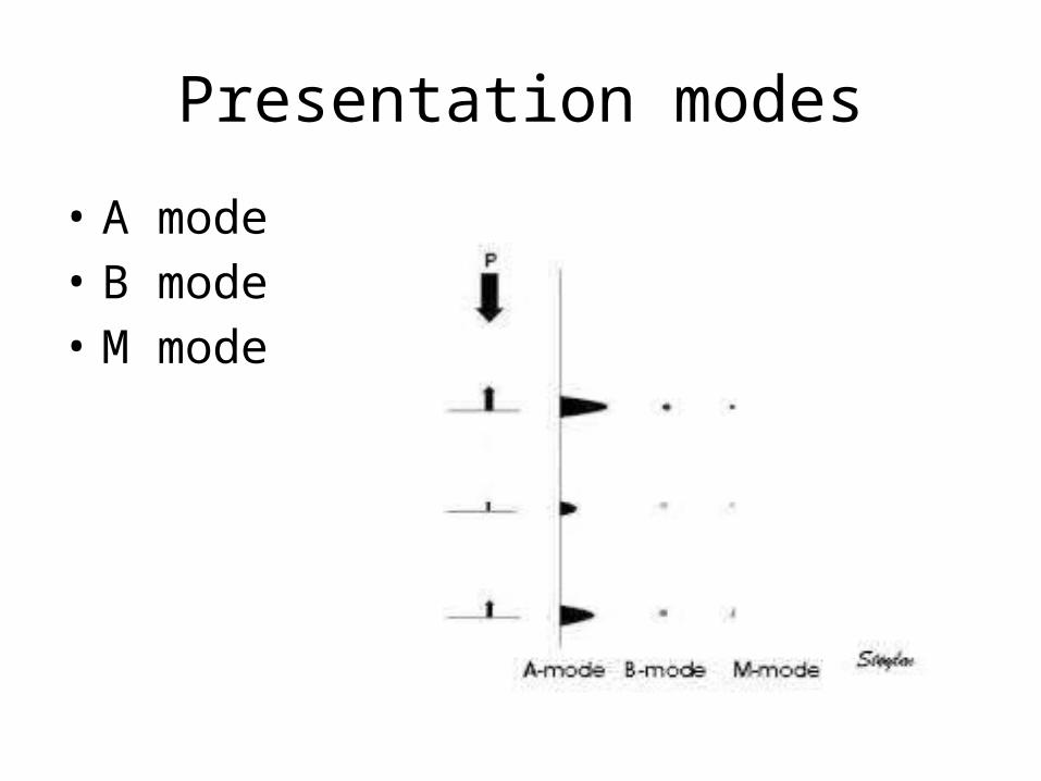
Presentation modes
• A mode• B mode • M mode

A Mode• A-mode systems have no memory, and a permanent record is obtained by
photographing the CRT monitor• The CRT represents a graph of echo voltage on y-axis to time on x-axis• A-mode may be used in ophthalmology or when accurate distance
measurements are required
B Mode
• B-mode is the electronic conversion of the A-mode and A-line information into brightness-modulated dots on the display screen
• The brightness of the dots is proportional to the echo signal amplitude
• The B-mode display is used for M-mode and 2D gray scale imaging

M Mode
• M-mode or T-M mode displays time on the horizontal axis and depth on the vertical axis
• The spikes of A-mode are converted into dots, and brightness replaces amplitude
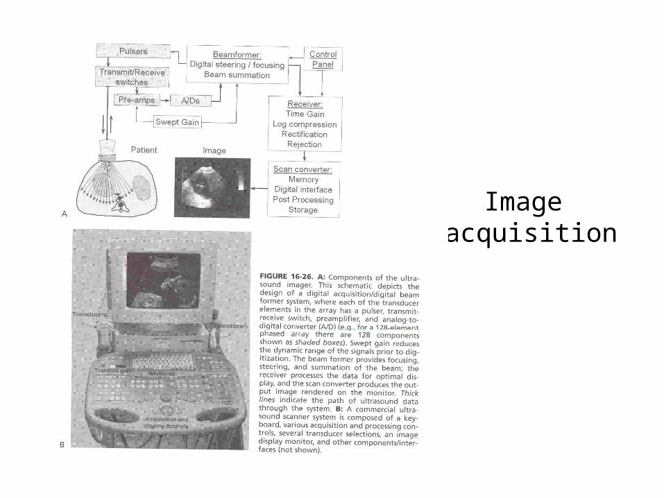
Image acquisition
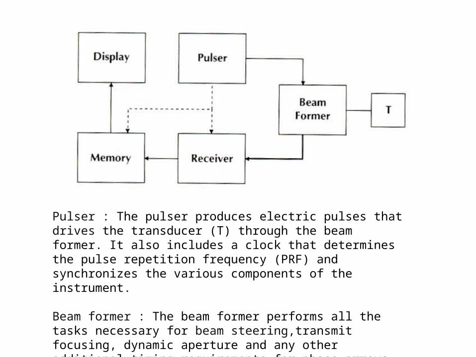
Pulser : The pulser produces electric pulses that drives the transducer (T) through the beam former. It also includes a clock that determines the pulse repetition frequency (PRF) and synchronizes the various components of the instrument.
Beam former : The beam former performs all the tasks necessary for beam steering,transmit focusing, dynamic aperture and any other additional timing requirements for phase arrays.
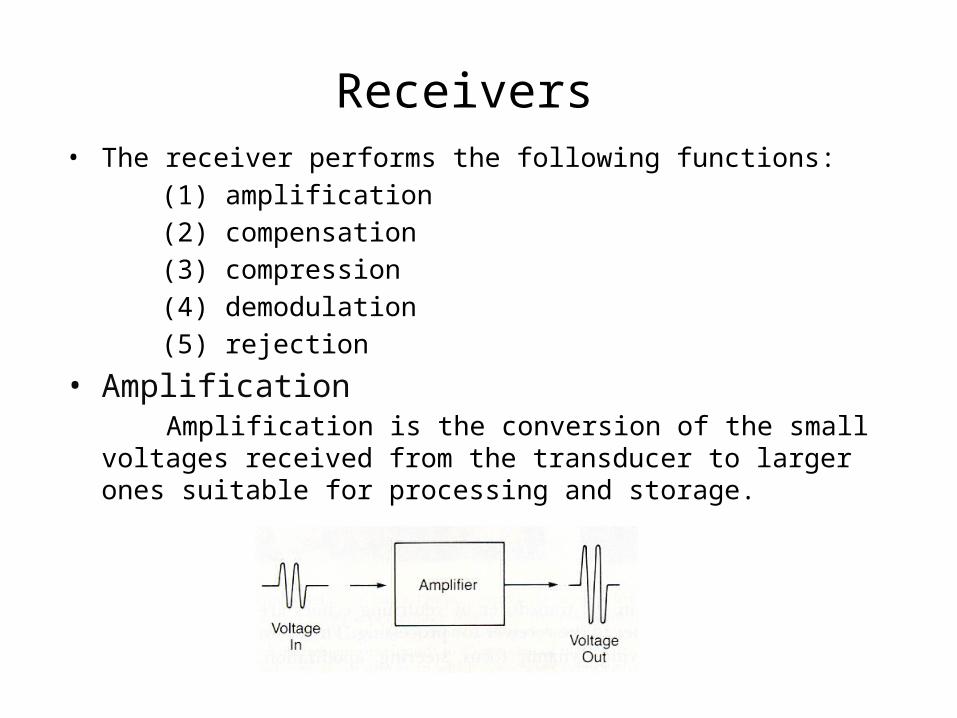
Receivers • The receiver performs the following functions: (1) amplification (2) compensation (3) compression (4) demodulation (5) rejection
• Amplification Amplification is the conversion of the small voltages received from
the transducer to larger ones suitable for processing and storage.
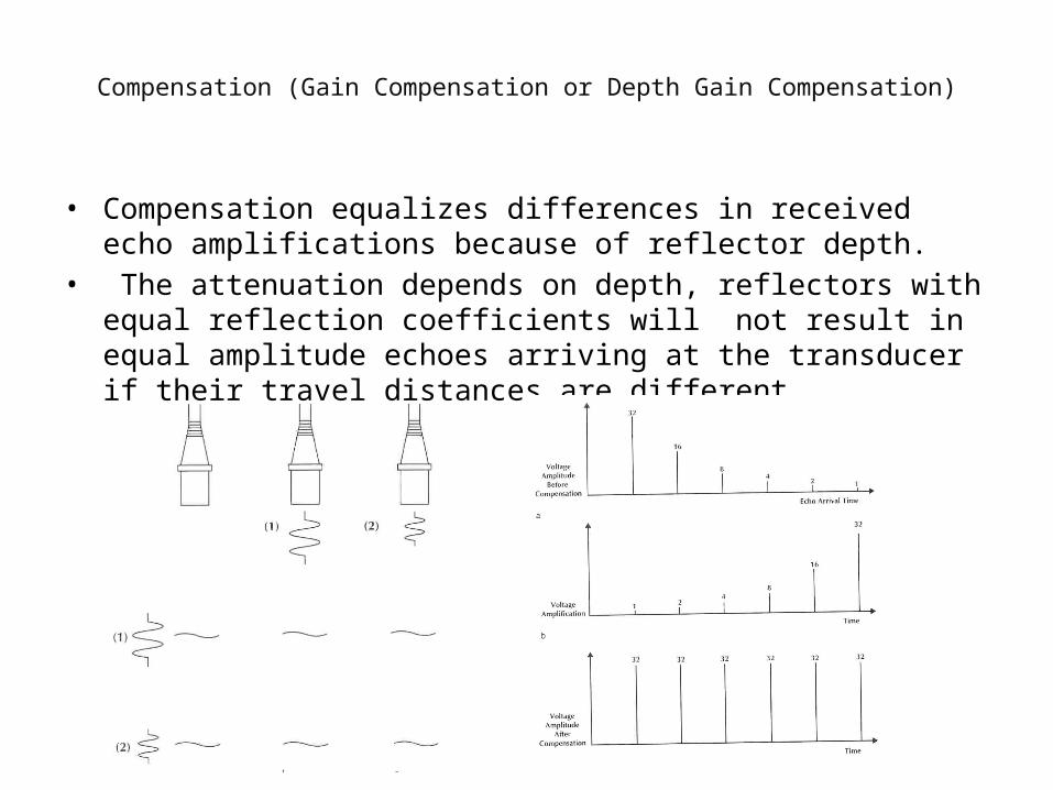
Compensation (Gain Compensation or Depth Gain Compensation)
• Compensation equalizes differences in received echo amplifications because of reflector depth.
• The attenuation depends on depth, reflectors with equal reflection coefficients will not result in equal amplitude echoes arriving at the transducer if their travel distances are different.

Compression
• Compression is the process of decreasing the differences between the smallest and largest amplitudes.
• This is accomplished by logarithmic amplifiers that amplify weak inputs more than strong ones. In other words, compression lowers the systems’ dynamic range.

Demodulation • Demodulation is the process of converting the voltage delivered to the
receiver from one form (radio frequency, RF) to another (video). • This is done by rectification and smoothing.

Rejection
• Rejection (also called suppression or threshold) eliminates the smaller amplitude voltage pulses produced by weaker echoes (multiple scattering from within tissue) or electronic noise.

Overall receiver process
Signal processing
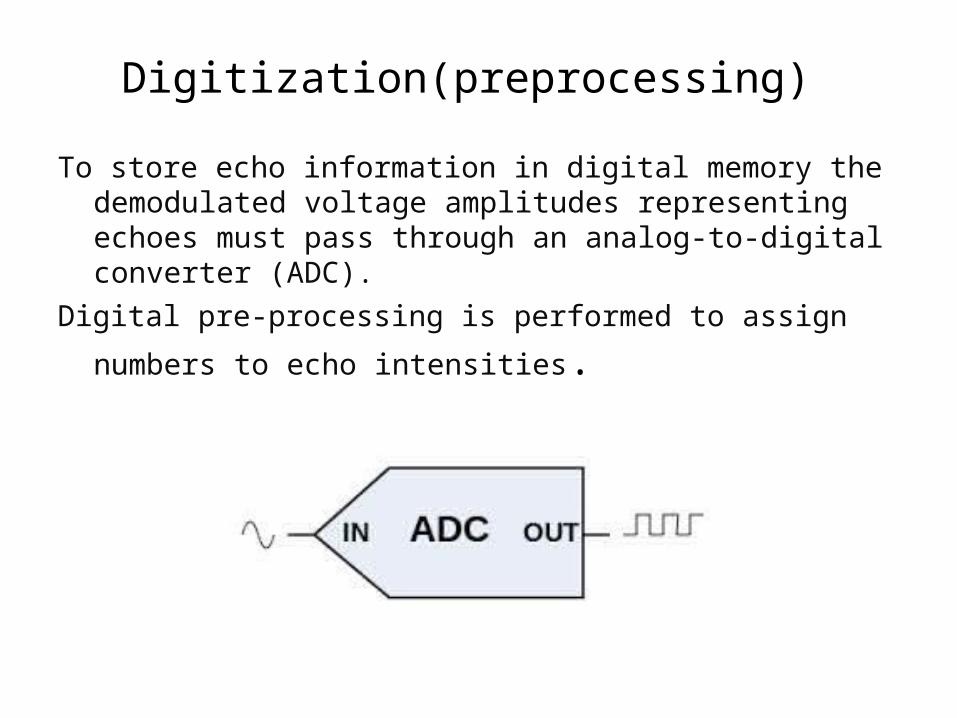
Digitization(preprocessing)
To store echo information in digital memory the demodulated voltage amplitudes representing echoes must pass through an analog-to-digital converter (ADC).
Digital pre-processing is performed to assign numbers to echo
intensities.

Contrast resolution
• For linear pre-processing assignments, the echo dynamic range (40 dB below) is equally divided throughout the gray levels of the system.
• The more gray levels (bits/pixel) that are used, the better the contrast resolution between adjacent pixels

Image Memory• Image memory used in ultrasound instrumentation are of the digital
type. These memories are some times called digital scan converters because they provide a means for displaying, using a television scan format information acquired in a linear or sector scan line format.
• The image plane is divided into a 512 x 512 pixel matrix, with each pixel being 8 bit (256 gray values) deep.

Image Storage• Image storage (without compression) is typically 0.25 MB/image• For real-time imaging (10 to 30 frames/s) this can amount to hundreds of
megabytes• Color images used for Doppler studies increase the storage requirements
further because of larger numbers of bits needed for color resolution (full fidelity color requires 24 bits/pixel, 1 byte each for the red, green and blue primary color)
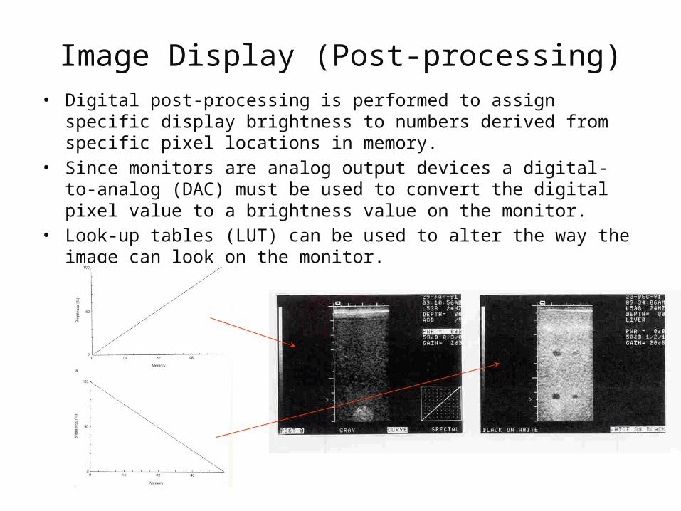
Image Display (Post-processing)• Digital post-processing is performed to assign specific display brightness
to numbers derived from specific pixel locations in memory. • Since monitors are analog output devices a digital-to-analog (DAC) must
be used to convert the digital pixel value to a brightness value on the monitor.
• Look-up tables (LUT) can be used to alter the way the image can look on the monitor.
Dynamic range
• The ratio of the largest to the smallest echoes processed by components of an ultrasound device is known as the dynamic range of the device.
• In general, the dynamic range decreases as signals pass through the imaging system because operations such as TGC and rejection eliminate small and large signals.
• Echoes returning from tissues can have dynamic ranges of 100 to 150 dB.
• The dynamic range in decibels may be easily converted to a ratio of amplitudes or intensities

Ultrasound image artifacts
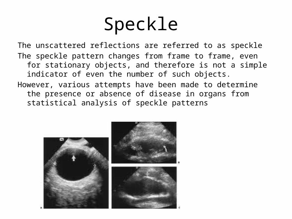
Speckle The unscattered reflections are referred to as speckle The speckle pattern changes from frame to frame, even for stationary
objects, and therefore is not a simple indicator of even the number of such objects.
However, various attempts have been made to determine the presence or absence of disease in organs from statistical analysis of speckle patterns

Shadowing and Enhancement
• If some object within the patient has a larger attenuation coefficient than the material that lies beyond it, then the settings of the TGC circuit that would provide appropriate compensation for normal tissue will under compensate and cause the region beyond the object to appear less echogenic.
• This phenomenon is referred to as acoustic shadowing.• Similarly, if the object in the path of the ultrasound beam has a lower
attenuation coefficient than its surroundings, acoustic enhancement may result.

Multiple pathway
• Various types of multiple-pathway artifacts occur in ultrasound images When an echo returns to a transducer, the imaging device assumes that the sound traveled in a straight line following a single reflection from some interface in the patient.
• The scan converter then places the brightness value at an appropriate location in the image.
• If the actual path of the echo involved multiple reflections, the echo would take longer to return, and the scan converter would place the interface at a greater depth in the image

Refraction
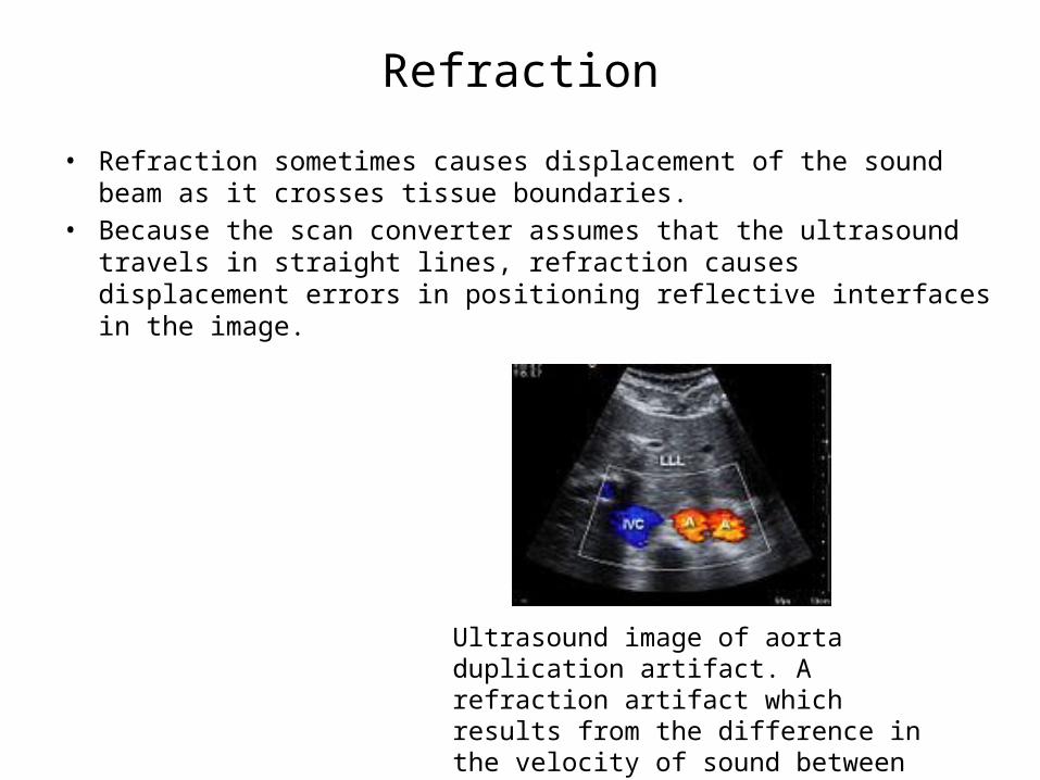
• Refraction sometimes causes displacement of the sound beam as it crosses tissue boundaries.
• Because the scan converter assumes that the ultrasound travels in straight lines, refraction causes displacement errors in positioning reflective interfaces in the image.
Ultrasound image of aorta duplication artifact. A refraction artifact which results from the difference in the velocity of sound between muscle and fat tissues