ultrasonic welding of thermoplastic composites: a
TRANSCRIPT

HAL Id: hal-03191184https://hal.archives-ouvertes.fr/hal-03191184
Submitted on 8 Apr 2021
HAL is a multi-disciplinary open accessarchive for the deposit and dissemination of sci-entific research documents, whether they are pub-lished or not. The documents may come fromteaching and research institutions in France orabroad, or from public or private research centers.
L’archive ouverte pluridisciplinaire HAL, estdestinée au dépôt et à la diffusion de documentsscientifiques de niveau recherche, publiés ou non,émanant des établissements d’enseignement et derecherche français ou étrangers, des laboratoirespublics ou privés.
Ultrasonic welding of thermoplastic composites: anumerical analysis at the mesoscopic scale relating
processing parameters, flow of polymer and quality ofadhesion
Arthur Lévy, Steven Le Corre, Arnaud Poitou
To cite this version:Arthur Lévy, Steven Le Corre, Arnaud Poitou. Ultrasonic welding of thermoplastic composites: anumerical analysis at the mesoscopic scale relating processing parameters, flow of polymer and qual-ity of adhesion. International Journal of Material Forming, Springer Verlag, 2014, 7 (1), pp.39-51.�10.1007/s12289-012-1107-6�. �hal-03191184�

International Journal of Material Forming manuscript No.(will be inserted by the editor)
Ultrasonic welding of thermoplastic composites: anumerical analysis at the mesoscopic scale relatingprocessing parameters, flow of polymer and quality ofadhesion
Arthur Levy · Steven Le Corre · ArnaudPoitou
Received: May 11, 2012
Abstract Ultrasonic continuous welding of thermoplastic composite plates isa very promising process of particular interest for the assembly of aeronauticslarge parts. Its modeling and simulation however suffers from the difficulty ofaccounting for the very different time scales that rule the thermo-mechanicalphenomena at the level of the adhesion zone. This problem was addressed inour previous works and led to an original simulation tool presented in (Levyet al [13], 2011, Eur. J. Mech. A/Solids, 30(4)). In this paper, the adoptedtime-homogenized multiphysical modeling of the flow at the mesoscopic scaleof the energy directors is first presented. Then, using the numerical software ina 2D approach, an extensive numerical parametric study of the process is pre-sented. The phenomena allowing welding are confirmed to be an initial strainconcentration in the energy director, and the formation of a flowing fold. Theinfluence of the following process parameters are finally investigated: ampli-tude of vibrations, holding force of the sonotrode, thickness of the plates, radiusof curvature at the tip of the director, angle of the director. Process efficiencyand weld quality is evaluated through simple indicators such as the equivalentstiffness analysis, the healing degree and the risk of porosity entrapment. Thepresent study, carried at the mesoscopic scale, provides a better understand-
A. LevyCenter for Composite Materials - University of Delaware, Newark, DE 19716, USA.Tel.: +1-302-831-8520Fax: +1-302-831-8525E-mail: [email protected]
S. Le CorreLaboratoire de Thermocinétique de Nantes, La Chantrerie, rue Christian Pauc, BP 50609,44306 Nantes cedex 3, France.E-mail: steven.le-corre@univ-nantes
A. PoitouInstitut de recherche en génie civil et mécanique, 1 rue de la Noë. 44321 Nantes Cedex 3,France.E-mail: [email protected]
2 Arthur Levy et al.
ing of the complex interactions between physical and process parameters andenable to draw important technological conclusions for the design of energydirectors.
Keywords ultrasonic welding · multiphysical modeling · numerical analysis ·healing · process parameters influence · geometry effects
1 Introduction
Thanks to their good specific properties, composite materials tend to replacetraditional materials such as metallic materials in the aeronautic industry.Whereas thermoset matrix composite were widely used in this industry for sev-eral years, thermoplastic matrix composites nowadays tend to replace them.Besides the good physico-chemical properties of the thermoplastic matrix suchas PolyEtherEtherKetone (PEEK), the ability to melt the matrix opens per-spectives to a variety of new and possibly more efficient forming processes.Contrary to thermoset composites, processes involving thermoplastic matricesdo not require the curing step, which can lead to two main improvements: (i)much shorter cycle times and (ii) no need for a confinement or autoclave step.Huge parts, which could not fit in any reasonable size stove may therefore bemanufactured without limit.
Of particular interest is also the welding possibility provided by thermo-plastic composites. Thanks to the ability of the matrix to melt, two partscan be assembled thanks to local heating and melting of the interface. Thedifficulty in welding organic composite then comes from their low thermalconductivity which therefore oriented technological investigations towards theidea of local heating of the interface between the two parts to be assembled. Atthis day, different technologies were considered such as resistance welding [21]or induction welding [3]. In those processes a metallic grid is needed and re-mains trapped at the interface after welding, which induces lower interfaceproperties.
This work focuses on the promising ultrasonic welding process, which doesnot suffer from such a drawback and may lead to more efficient assemblies.In this process, in order to achieve the local heating, triangular bulges, calledenergy directors, are molded on one of the plate to be welded. The assemblyis then positioned under a tool called sonotrode which applies simultaneouslya constant load and a harmonic ultrasonic compression (Fig. 1(a)). It is nowcommonly known that the strain, located in the director, induces heating be-cause of viscous dissipation [24], [4], [18]. The director then melts and flows atthe interface to allow welding (Fig. 1(b)).
First experiments were performed by EADS IW with the so-called “contin-uous process”, patented in 2007 by Soccard [19], where the sonotrode movesalong the energy director direction. First results reveal a good mechanicalquality of the welding. In particular the advance of the sonotrode enables airremoval along the director and avoids the trapping of bubbles. Moreover, itwould allow one to assemble large parts using continuous weld lines, where

Ultrasonic welding of thermoplastic composites. 3
(a) Assembly. (b) Flow at the interface.
Fig. 1: Principle of the ultrasonic welding technique.
the “static” process (without sonotrode advance) limits the welding area tothe size of the sonotrode. This opens possibilities for this process to be used atan industrial level to assemble large parts keeping an excellent weld quality.
The main phenomena occurring in this process, initially outlined by Be-natar and Gutowski [4] can be summarized as: (i) mechanics and vibrationof the parts, (ii) viscoelastic heating, (iii) heat transfer, (iv) flow and wet-ting, and (v) intermolecular diffusion. Using a time homogenization techniquebased on the use of double time-scale asymptotic expansions, a simultaneousmodeling of the vibration, heat transfer and flow was proposed in a previouswork [14]. This theoretical analysis showed that thanks to the good time scalesseparation implied by such a process, the heating and flow of the energy di-rectors could be modeled by three problems, two macro-temporal ones, at thetime scale of the squeezing, that enable to describe the average heating andflow of the polymer, and a micro-temporal one, at the time scale of one periodof vibration, that enable to compute the self-heating of the viscoelastic mate-rial. A specific numerical tool was then developed in order to simulate the flowof polymer at the interface [13]. This original finite element software, basedon the use of an Eulerian framework associated with level-set functions to de-scribe the evolution of the polymer outer surface, was validated and proved tobe able to describe the main physical phenomena of such a complex industrialprocess.
In this paper, basing on the use this simulation tool, we investigate theinfluence of various process parameters on the quality of the welding and bringnew elements for a better understanding and optimization of this technology.In section 2, we remind the modeling and simulation tools and introduce twocriteria that can qualify a good welding, in order to compare the efficiency ofdifferent technical solutions. In section 3, a reference simulation, with realisticmaterial parameters typical of PEEK polymer composites, is first detailed. Itenables to analyze the two coupled phenomena at the origin of welding: heatingand flow. As a major objective of this paper, the influences of five parametersof high interest for the industrial manufacturer are then investigated: the twomain processing parameters, (i) amplitude of vibration and (ii) holding force of

4 Arthur Levy et al.
mechanical dissipation
matetrial properties
change
geometry change
geometry change
mechanical dissipation
matetrial properties
change
Elasticitylinear
Harmonic boundary condition
FlowSqueezing of the director
Transient thermicssource term given by the
mechanics
Fig. 2: Modeling of the thermomechanical problem using three coupled bound-ary value problems.
the sonotrode, (iii) the effect of plates thickness that shows the technologicallimitations of such a process, and the influence of the director’s geometrythrough the variation of (iv) the smoothness of the tip and (v) the sharpnessof triangles.
2 Methods
By opposition to the studies at themacroscopic scale (see for example Ha Minh[9]), where one is interested in phenomena such as vibrations, dimension toler-ance or residual stresses effects, this work focuses on the so-called mesoscopicscale. In this approach, which has been the subject of previously cited works[24],[4], [18], the objective is to understand the effect of process parameters onthe welding mechanisms and the quality of the adhesion at the interface. Onetherefore has to consider the heating and flow of the energy directors at theinterface between the two composite plates, which height are about 300µm.The mesoscopic scale discussed in the following is defined such that it has acharacteristic dimension of 100µm.
2.1 Modeling and simulation of the process
2.1.1 Multiphysical modeling
This rather classical thermo-mechanical problem including self-heating of apolymer presents a strong difficulty due the huge difference between the weld-ing time (∼1s) and the vibration period (∼10−5s) which makes a full directsimulation of the problem unaffordable. This problem was addressed in ourprevious work [14], basing on a time-homogenization technique which leads toan original model consisting of three coupled physics as illustrated in Fig. 2.

Ultrasonic welding of thermoplastic composites. 5
Problem 1: An elasto-statics problem at the short time scale describes theeffect of the vibration induced by the sonotrode. The Young’s modulusdepends on temperature according to the following law, which was fittedfrom experimental data on PEEK provided by several authors [4], [8], [15]:
E (θ) = 2, 8 109
0.5− arctan(θ[◦C]−140
20
)π
+ 1, 6 108 Pa. (1)
Problem 2: The heating at long time scale is described by a usual conductionconvection problem where a self heating source term Q due to the vibrationis added and computed from problem 1 as:
Q =ωE′′
2〈ε : ε〉 (2)
where ω is the pulsation of the sonotrode, E′′ is the loss modulus of thepolymer, and ε is the elastic strain [24], [4], [25], [22], [14]. In this equation,〈·〉 operator represents the average over one time-period of vibration.
Problem 3: A Stokes problem then describes the flow of polymer. In order toaccount for the shear thinning and large strain effects in the polymer, aCarreau type law is adopted for the viscosity evolution:
η = η0(T )(1 + (λcDeq)
2)m−1
2
, (3)
where η0(T ) denotes the Newtonian viscosity at a given temperature T , λcthe Carreau characteristic time, m the Carreau index and Deq =
√2D : D
the equivalent strain rate, D being the strain rate tensor. The Newtonianviscosity is furthermore assumed to depend on temperature according toan Arrhenius law:
η0 (T ) = A exp
(Ea
RT [K]
)(4)
where A is a material parameter, Ea is the activation energy of the materialand R = 8.31 JK−1mol−1 is the gas constant. These choices where directlyinspired by results of the literature on the rheology of PEEK [17] and usedvalues are given in table 1.
2.1.2 Numerical tool
In order to solve the three boundary value problems on the initially triangularshape of the director, a specific numerical tool was developed [13]. It enablesto handle both the multiphysical couplings and the large geometry changes, asthe energy director flows from its initial triangular shape till becoming a thinfilm at the interface. All couplings are handled using an iterative method thatensures a rigorous solution at convergence. Large geometry changes are treatedwithin an Eulerian framework where the interface is described precisely using alevel-set method. Due to computation time limitations, the problems presented

6 Arthur Levy et al.
h/10
polymer
polymer
air
composite
composite
80 µm
80 µm
3 mm
3 mm
h=0.3 mm
9008µm
y
x
levelset 1
levelset 2
levelset 3
levelset 3
Fig. 3: Initial domain and materials used in the simulations.
in the following are solved on a two-dimensional domain in a plane strainassumption. We therefore consider the so-called “static” ultrasonic process,where the sonotrode does not move. The three-dimensional simulations stillrequire numerical improvements that will be addressed in further works.
2.1.3 Simulation cases
Thanks to symmetries, the resolution domains is restricted to one half of anenergy director and to one half step between two directors, as shown in Fig. 3.
The height of the domain allows one to consider the whole upper and lowercomposite plates. Fig. 3 shows that three level-set fields describe the geometry.The first one describes the energy director/air interface, the second one thelower plate/air interface, and the third one the composite/polymer interface.

Ultrasonic welding of thermoplastic composites. 7
Fig. 4: Boundary conditions for the two mechanical problems: (a) elasticity,(b) fluid mechanics.
Note that, according to the industrial process, both composite plates have asuperficial layer of neat polymer.
Boundary conditions for the mechanical problems are illustrated on Fig. 4.A symmetry condition is imposed on the left boundary. The vertical displace-ment of the lower part is imposed to zero in the elastic problem. For the fluidflow problem, the vertical velocity is imposed to zero on the internal boundarycorresponding to the upper part of the lower plate. This allows one to simplifythe handling of contact between the energy director and the lower plate. Thelower plate is therefore considered as rigid in the flow problem.
The right boundary is let free in both the elastic and fluid problems, whichenables to overcome the difficulty of extracting the air. Notice that this is closerto the condition encountered in the “continuous” process where the extractionof air is possible along the third dimension. As visible from table 1, it is alsoworth noting that the air mechanical properties are very low compared to thepolymer, so that it will not affect the flow simulations.
On the upper boundary, a vertical displacement, corresponding to the am-plitude of the sonotrode vibration, is imposed in the elastic problem. A verti-cal homogeneous stress distribution, corresponding to the holding force of thesonotrode, is imposed in the fluid mechanics problem.

8 Arthur Levy et al.
In the thermal problem, all boundaries are assumed perfectly insulated.Due to the short processing time and the rather low temperatures, thermalexchanges with the external medium do not have to be considered here. Doingso, the temperature raise in the system will be due only to the mechanicaldissipation.
2.2 Quality of welds
First results obtained by Levy et al [13] show that the thermomechanicaland topological evolution of energy directors is very complex so that it may bedifficult to compare the efficiency of different processing conditions or differentgeometries. Probably due to the semi-crystalline nature of PEEK, the processcan be decomposed into two rather well separated steps: (i) the initial heatingdue to the tip effect and (ii) the flow stage due to the softening of the polymer.It is often non trivial to decide whether one evolution is better than the otherone so that some objective criteria are required. In particular, it is at leastimportant to predict the degree of adhesion one can expect from a given setof processing parameters.
2.2.1 Contact
The first requirement for adhesion is obviously the presence of a contact at amicroscopic scale, called intimate contact. It mainly depends on the surfaceroughness, the pressure between the two plates and the polymer behavior, asdiscussed in Lee and Springer [12] or Mantell and Springer [16].
In our case, the mesoscopic scale retained will be considered as smallenough to determine whether the intimate contact is achieved or not. Theadhesion process is therefore assumed to start when the two surfaces describ-ing the energy director flow and the lower plate surface get in contact.
2.2.2 Healing
Once this intimate contact is achieved, the resulting interface can disappearin time. This is physically realized by diffusion of the polymer macromoleculesacross the interface [12] which can be modeled by the reptation theory [7].In order to define the quality of the healing, many author define the healingdegree Dh as the ratio between the instantaneous interfacial bond strengthand the ultimate interfacial bond strength [12, 20, 5]. Those authors proposeto model this healing degree evolution using the so-called welding time tw, forwhich a full interface bond strength is obtained :
∂Dh
∂t=
(1
tw (T )
) 14
. (5)
Note that for low molecular weight polymers, this welding time is similar tothe reptation time; but that for high molecular weight, it might be smaller

Ultrasonic welding of thermoplastic composites. 9
(full strength is obtained before a full reptation of the macromolecule) [26].The welding time dependency with temperature T is classically modeled usingthe Arrhenius law:
tw = Arep exp
(EaRT
). (6)
Arep being a pre-exponential coefficient depending on the material.As suggested by Lee and Springer [12] or Cho and Kardos [6], the crys-
tallinity of the matrix affects the accuracy of equation 5. Indeed, the crystallamella in the semi-crystalline PEEK below melting temperature act as ob-stacles to the reptation and healing. Nonetheless this model has been widelyused to model auto-adhesion in forming processes of semi-crystalline PEEKmatrix composite [12, 16, 20, 5, 1, 2, 26, 11, 23, 10]. In the following, we willpresent degrees of healing computed using the equation :
Dh =
ˆ t
t0
1
tw (T )14
dt. (7)
Nevertheless, we have to keep in mind that this value is well overestimatedsince crystallization is likely to limit healing. To account for this limitation bycrystallization, a full multiphysical model predicting the melting and crystal-lization phenomena should be performed.
In the simulations presented in next sections, material parameters of equa-tion (6) for the welding time are given in table 1. They were deduced fromrheological data provided in [17], and tw was identified as the longest relaxationtime.
3 Results and discussion
The numerical tool used was already qualitatively validated by comparingsimulation with experimental order of magnitude of the process [13]. It is hereused to understand the physical mechanisms of ultrasonic welding as well asthe influence of the main processing parameters.
3.1 Reference simulation
In this first section, a simulation is performed using material parameters givenin table 1, as close as possible to experimental data. Besides its usefulness asa reference when studying the influence of the process parameter, this simula-tion allows one to understand the physical phenomena that occur during theprocess.

10 Arthur Levy et al.
Table 1: Material parameters used in the reference simulation.
Polymer Air Composite
Young’s modulus E (Pa) eq. (1) 5× 10³ 9.3× 10⁹
Poisson coefficient ν 0.4 0 0.2Newtonian viscosity A (Pa.sm) 5.6× 10⁻³ 2× 10⁻⁵ 10activation energy Ea (J) 7.44× 10⁴ 0 7.44× 10⁴
Carreau time λ (s) 1 0 1Carreau power m 0.54 1 1
conductivity k(Wm−1K−1
)0.24 2.6× 10⁻² 0.72
heat capacityρc(Jm−3K−1
)1.3× 10⁶ + 4500T [◦C] 103 2.22× 10⁶
loss modulus E′′ (Pa) 20 106 0 0
sonotrode pulsation ω(rad.s−1
)1.25× 10⁵ − −
healing coefficient Arep (s) 7.3× 10⁻⁶ − −
Ksupcomp
Kinfcomp
Γinf
Γsup
Kd
Γ2
Γ1
〈σyy〉Γsup
(a) Definition of equivalentstiffnesses of the different partsof the system.
(b) Evolution of the equivalent stiffnesses duringwelding.
Fig. 5: Analysis of energy localization in the process.
3.1.1 Phase I: heating
During the initial phase the vibration strain is concentrated at the tip ofthe energy director. In order to quantify this localization, we consider theequivalent stiffness of three subdomains of the system, as shown on Fig. 5(a).
The stiffness of each zone is computed as the ratio between the verti-cal stress average and the average displacement difference between the twohorizontal interfaces (successively Γsup, Γ2, Γ1 and Γinf ) bounding each sub-domain. Fig. 5(b) shows that the equivalent stiffness Kd of the central part,containing the director is almost five times lower than the stiffness of the platesKsup and Kinf .
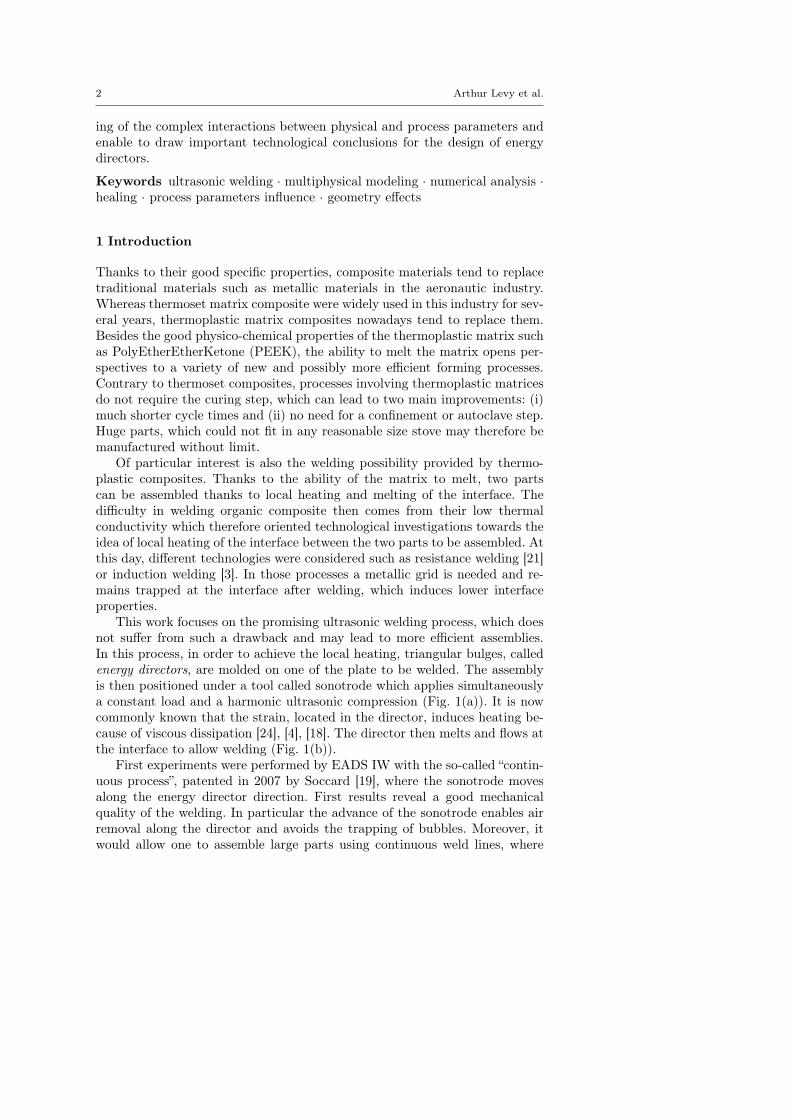
This is explained by the triangular geometry of the director. It induces astrain concentration that produces a localization of the thermal dissipation (2)which leads to a local heating of the tip of the director, as shown on Fig. 6.
Ultrasonic welding of thermoplastic composites. 11
23
32
41.1
50.1
59.2
68.3
77.3
86.4
95.4
104
114
TEMPERATURE
Fig. 6: Temperature field in the initial phase at time t = 0.03 s for the referencesimulation case.
This is the so-called tip effect which can be quantified with the proposedequivalent stiffness estimator. One may think that the heating softens thematerial and improves the localization and the tip effect. But once the polymersoftens, it begins to flow and the sharp geometry is rapidly lost. Thereforethe equivalent stiffness of the director slightly therefore in time, as shown onFig. 5(b). Due to the slow heat diffusion, the temperature then remains locatedaround the energy director, which stiffness is 4 to 5 times smaller than that ofthe composites plates. In such a case, typical of current industrial conditions,one can see that the objective of bringing the energy directly at the interfaceis reached.
3.1.2 Phase II: flow
The local heating at the tip of the director softens the polymer which, in thesecond phase, flows at the interface. The highly localized tip effect initiates aspecial flow morphology which is referred to as fold morphology (cf. Fig. 7).It has already been highlighted and successfully compared to experimentalmorphology in previous work [13].
Fig. 8 represents the squeezing ratio evolution which is the displacementof the upper plate normalized by the energy director’s initial height. It clearlyillustrates the transition between the first stage (before t = 0.04 s) where thetip effect occurs with almost no shape modifications and the second stage offlow and squeezing. In that second phase the squeezing speed progressivelylowers as the fold fills the gap between the plates.
Note that the simulation does not account for crystallization phenomena.Nonetheless, it will influence the flow as mechanical properties are evolving

12 Arthur Levy et al.
Fig. 7: Free surface evolution for the reference simulation: initiation and ex-pansion of the fold.
Fig. 8: Squeezing ratio vs. time.

Ultrasonic welding of thermoplastic composites. 13
0
0.025
0.05
0.075
0.1
0.125
0.15
0E+00 2E-04 4E-04 6E-04 8E-04 1E-03
Healin
g d
eg
ree
Position on the interface (m)
t=0,15st=0,25 s
Fig. 9: Healing degree profiles along the welded interface at time t = 0.15 sand t = 0.25 s
with the degree of crystallization. Therefore the presented results will looseaccuracy when the temperature gets colder and crystallization occurs.
3.1.3 Contact and healing
The observed fold morphology (see Fig. 7) provides suitable conditions foradhesion. The hot flow front moves along the lower plate surface and achievesintimate contact, at least at the mesoscopic scale of the study. One can remarkthat a progressive (continuous) evolution of the fold along the lower plate isdesired to ensure intimate contact and avoid air entrapment.
Thanks to this evolution, the local heating at the vicinity of the interfaceis ensured by the convection of the hot polymer, heated by the tip effect. Tocomplete this analysis, Fig. 9 presents the healing degree as defined in sec-tion 2.2.2, computed along the interface for different times. As highlighted insection 2.2.2, the computed degree of healing is to be considered as a qualita-tive measurement because it does not account for crystallinity. Nonetheless, itshows the adequacy of the mesoscopic approach to study adhesion.
At the end of the flow phase, around t = 0.25 s, Dh is far from reaching 1so that the interface would still not be healed at this time. This may be actu-ally the case, but should be confirmed by more precise simulations includinglocal adaptative mesh refinement and better material properties identification.Furthermore, the rapid evolution of the healing degree between t = 0.15 s andt = 0.25 s reasonably lets imagine that a good healing can be achieved duringthe following cooling phase. In order to predict the final quality of the adhesiona study of the following cooling phase is required.

14 Arthur Levy et al.
Finally, at this stage, more than a quantitative estimator of the adhesion,the healing degree allows one to estimate and predict the homogeneity of theadhesion at the interface. For instance, the healing degree profile on Fig. 9for time t = 0.25 s exhibits a zone of lower healing degree. This is caused bythe fold evolution that has not been sticking along the lower plate during thewhole flow. Intimate contact was lost for few instants.
The analyses of the heating and flow phases is possible thanks to our novelsimulation tool that handles simultaneously both phenomena. In the next sec-tions, we propose a parametric analysis and discuss the influence of someprocess parameters on those two interdependent stages of the mesoscopic pro-cess.
3.2 Parametric analysis
In this section, the influences of some process parameters on the heating andflow of polymer are studied. Since the numerical tool is qualitative, resultswill only highlight trends and do not pretend to predict accurate quantitativevalues.
3.2.1 Amplitude of vibration of the sonotrode
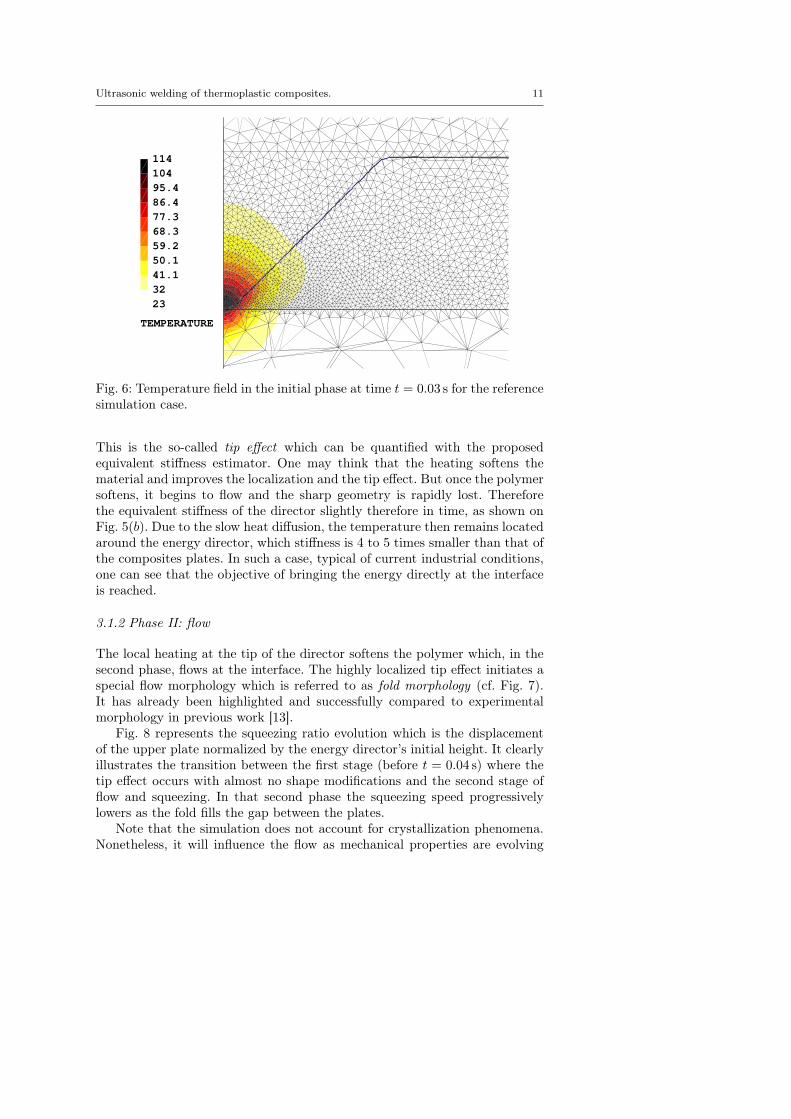
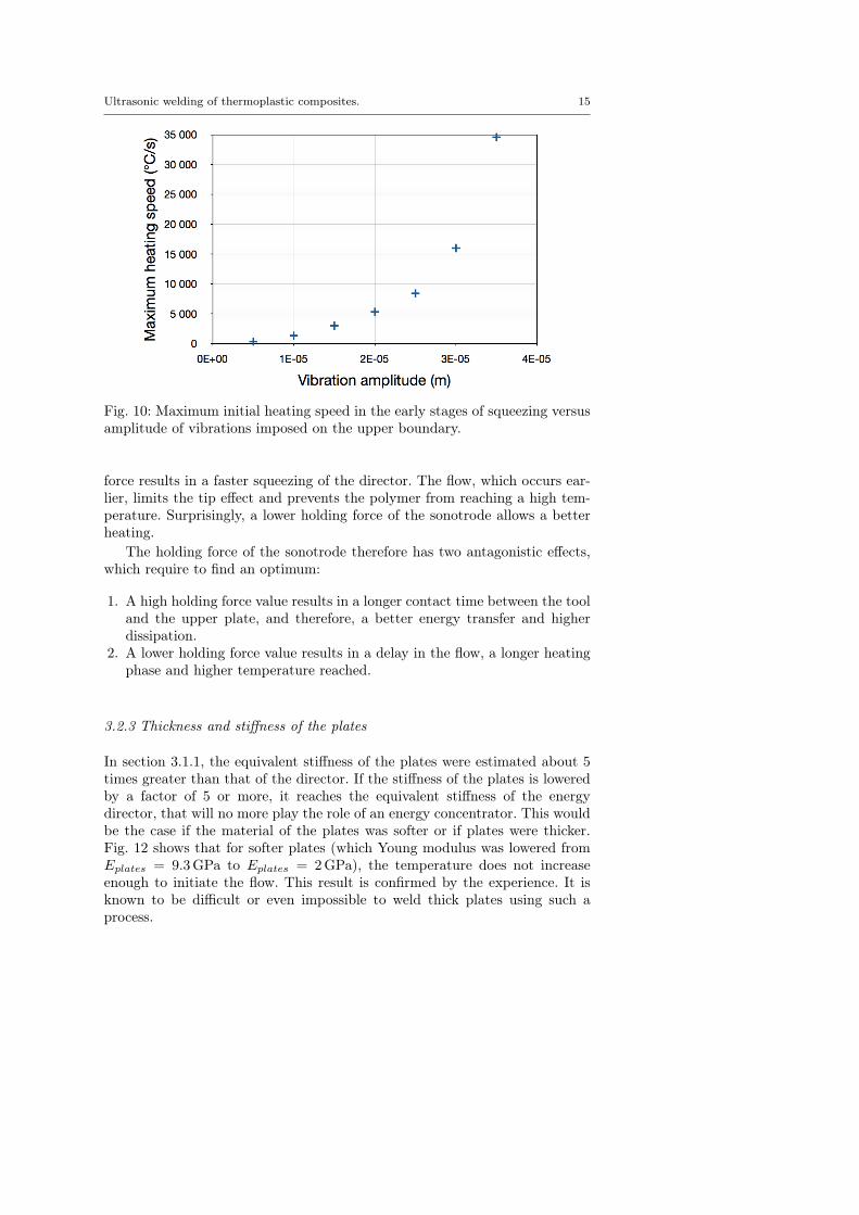
The dissipation term (2) is proportional to the square of the elastic strain. Theprocess is therefore highly dependent on the amplitude of vibration imposedon the upper boundary by the sonotrode. The initial maximum heating speedat the tip of the director is represented versus imposed amplitude on Fig. 10.As expected, the quadratic effect is exactly recovered for this heating phase.
One has to notice that the sonotrode does not impose a strictly sinusoidaldisplacement to the upper plate. In practice, due to inertia effects, the con-tact may be lost causing hammering as explained by Nonhof and Luiten [18].Hence, increasing vibration amplitude of the sonotrode may lengthen the lossof contact with the upper plate. The quadratic dependence observed in ourmesoscopic simulation may therefore not be observed in practice.
3.2.2 Holding force of the sonotrode
Besides the vibration imposed by the sonotrode, the contact time betweenthe sonotrode and the upper plate is highly dependent on the holding forceof the sonotrode, as shown by Ha Minh [9]. Hereunder, we do not considersuch macroscopic effects and focus on the effect of the holding force on themesoscopic flow at the interface, under the assumption of a permanent contactbetween the sonotrode and the upper plate.
Fig. 11 shows that when increasing the holding force, the maximal temper-ature at the tip of the director is lowered. Indeed, imposing a higher holding
Ultrasonic welding of thermoplastic composites. 15
Fig. 10: Maximum initial heating speed in the early stages of squeezing versusamplitude of vibrations imposed on the upper boundary.
force results in a faster squeezing of the director. The flow, which occurs ear-lier, limits the tip effect and prevents the polymer from reaching a high tem-perature. Surprisingly, a lower holding force of the sonotrode allows a betterheating.
The holding force of the sonotrode therefore has two antagonistic effects,which require to find an optimum:
1. A high holding force value results in a longer contact time between the tooland the upper plate, and therefore, a better energy transfer and higherdissipation.
2. A lower holding force value results in a delay in the flow, a longer heatingphase and higher temperature reached.
3.2.3 Thickness and stiffness of the plates
In section 3.1.1, the equivalent stiffness of the plates were estimated about 5times greater than that of the director. If the stiffness of the plates is loweredby a factor of 5 or more, it reaches the equivalent stiffness of the energydirector, that will no more play the role of an energy concentrator. This wouldbe the case if the material of the plates was softer or if plates were thicker.Fig. 12 shows that for softer plates (which Young modulus was lowered fromEplates = 9.3GPa to Eplates = 2GPa), the temperature does not increaseenough to initiate the flow. This result is confirmed by the experience. It isknown to be difficult or even impossible to weld thick plates using such aprocess.

16 Arthur Levy et al.
Fig. 11: Maximal temperature in the director versus time for different holdingforces of the sonotrode, imposed as a uniform normal stress with equivalentresulting force.
Fig. 12: Temperature field at time t = 5 s for soft plates where Eplates = 2GPaand for the same holding force as in the reference simulation.

Ultrasonic welding of thermoplastic composites. 17
Fig. 13: Maximum temperature in the director at time t = 0.03 s versus radiusof curvature r at the tip of the director.
3.2.4 Radius of curvature at the director’s tip
In the reference simulation, the radius of curvature r at the tip of the directoris 10% of the director’s height h, according to the real geometry. Simulationswith different radii of curvature were also performed. Fig. 13 represents themaximum temperature at the director tip during the initial heating phase,versus the radius of curvature r. This temperature decreases somewhat linearlywhile increasing r. As expected, sharper energy directors result in a fasterheating during the initial phase.
In order to illustrate the tip effect on the flowing phase, Fig. 14 presentsa comparison of the resulting flow fronts for two different radii. As the flowis not initiated as quickly in both configurations, plots are given for differentinstants were the fold morphology is comparable. In addition, the differencebetween both temperature fields is also given. Fig. 14 thus shows that thetemperature field and deformed shape for r = 0.05h is very close to the onefor r = 0.2h taken a bit earlier. Indeed, the relative difference
T (r = 0.05h, t = 0.065 s)− T (r = 0.2h, t = 0.09 s)
T (r = 0.2h, t = 0.065 s)
is small and never exceeds 0.1. A smoother director therefore only leads to adelay in the flow.
3.2.5 Angle of the triangular director
In this last section, simulations obtained with different angles of the directorare analyzed. The different simulations were performed using equal amounts

18 Arthur Levy et al.
r=0.05h - t=0.065s
r=0.2h - t=0.09s
relative
temperature
difference
Fig. 14: Deformed shapes and relative temperature difference between: - aninitial tip radius r = 0.05h at time t = 0.065 s and - an initial tip radiusr = 0.2h at time t = 0.09 s.
Fig. 15: Maximum temperature at the tip of the director versus time for dif-ferent angles of directors.
of polymer (which means different height of director) and equal radius ofcurvature at the tip.
Fig. 15 represents the temperature at the tip of the director versus timefor different angles. Since the radius of curvature is identical, during the initialphase, the increase of temperature does not depend on the angle. During the

Ultrasonic welding of thermoplastic composites. 19
53°/2
127°/2
Fig. 16: Temperature fields for equivalent macroscopic squeezing ratios. Initialangle of 53◦ at time t = 0.035 s and 127◦ at time t = 0.05 s.
Fig. 17: Squeezing ratio versus time for different initial angle of director.
flow phase, the temperature stabilizes (final times on the graph). Moreover,the transition appears later for larger angles. This is explained by the betterthermal insulation of a sharper geometry which limits the diffusion of heat inthe director. The temperature is indeed more localized and higher, as shownon Fig. 16. If we now look at the squeezing time, as presented on Fig. 17, it isclear that sharper directors enable faster processing conditions.
However, considering Fig. 15 again, we observe a sharper transition regimefor small angles. This is associated with the moment when the fold reachesthe height of the gap, leading to a stress transfer over a much wider zone. As

20 Arthur Levy et al.
53°/2
127°/2
t=0,21s
t=0,32s t=0,48s
t=0,09s
t=0,21s
Fig. 18: Flow morphology for two extreme initial angles of energy directors.
illustrated by Fig. 18, the drawback of sharp energy directors, due to the morepronounced fold, is that they will lead to more air entrapment, indicated byan arrow on the figure.
Those simulation clearly show that non evident conclusion can be drawnregarding the geometry of energy directors. Results however show that anoptimum shape could be found using a more complex geometry, with first arather sharp end in order to better concentrate the heating, followed by aprogressive enlargement, that would ensure better contact conditions.
4 Conclusion
In this paper, we presented the application of an original simulation tool tothe physical analysis of the ultrasonic welding process. The two main strengthsof this code, already presented in a previous paper [13], consist in the use of(i) a level set technique within an Eulerian framework that enables to handlethe large geometry changes with a precise description of the physical surfaces,and of (ii) an iterative multiphysical solver that allows one to solve rigorouslytwo mechanical problems and a thermal problem. At this stage, this new codeis still a demonstrator but is not optimized for large computations. It is stillnot applicable to the simulation of the full 3D continuous process involving anadvance of the sonotrode along the energy director (the out of plane directionin our 2D representation).
However, much of the results presented here in the 2D case can be extendedto 3D situations. For instance, the fact that a high sonotrode holding force willsqueeze the director can be extended to the continuous process, the difficultyto weld thick plates was also already observed experimentally. On the other

Ultrasonic welding of thermoplastic composites. 21
hand the results concerning the influence of the director angle on the flowmorphology can not be extended directly to the continuous welding process.Nonetheless they provide some expectations. Finaly, the 2D results give abetter understanding of the complex and non evident interactions betweengeometry, process parameters, thermics and mechanics.
A particular effort was made in this work to choose realistic material pa-rameters and laws that can represent at best the semi-cristalline behavior ofthe PEEK. Thanks to those models, results show that one can distinguish twostages in the welding process: (i) a stage of localized heating due to the tipeffect until reaching a sufficient drop of mechanical properties followed by (ii)a flow stage where a fold of polymer is formed and moves forward until fillingthe gap between the plates and eventually achieving adhesion. One may noticethat the mesoscopic scale retained in this study is inescapable for analyzingthose phenomena. The study must therefore be carried at this scale to physi-cally determine the adhesion or the formation of porosity. We also remind thatthe results and especially the healing degrees presented above are obtained af-ter the flow phase. The subsequent cooling phase, that was not studied in thiswork, is needed if one wants to fully predict the final quality of the weld.
In order to better understand the complex interactions between physicalphenomena, the present work then focused on the analysis of several parame-ters on both stages of the process, trying to draw conclusions on the potentialquality of the realized assembly. Several expected important technological re-sults were first confirmed by this study:
– The amplitude of vibrations acts directly on the provided energy and gov-erns the local heating rate. However, in practice, one would have to accountfor the hammering phenomenon that limits this effect and therefore reducesthe overall efficiency of the process.
– The geometry of the tip of directors is essential to reach rapidly the meltingtemperature. One should use a tip radius of curvature as small as possible.
– The analysis in equivalent stiffness is a very useful and simple tool one canobtain by a simple elastic calculation. It enables to quantify the energyconcentration at the interface, initial requirement for the efficiency of thewhole process.
Two other important results which are less evident where also highlighted:
– Firstly, a too high holding force leads to a poor welding for it squeezes theenergy director before it has reached a high temperature.
– Secondly, results regarding the geometry show two antagonist effects. Asharp director shape leads to a rapid and well localized heating, thus en-abling the creation of a hot fold promoting a good adhesion. However, thefinal squeezing of the fold may entrap porosities and so weaken the realizedjoin. On the contrary, a flat director shape, though slower for the heatingstage, leads to a more progressive filling of the interface with less porosities.
The parametric analysis detailed in this paper therefore brings a deeper un-derstanding of the ultrasonic welding process which is essential for any further

22 Arthur Levy et al.
optimization of processing parameters. Nevertheless, in order to accurately de-termine the final healing degree of the interface, some additional work is stillneeded. First, the final cooling phase is to be investigated. Then, the numericaltool has to be validated and maybe improved, in order to give more accurateresults, especially concerning the healing degree evolution which depends oncrystallization. These improvements may give quantitative results concerningthe “static” process, where the sonotrode does not advance. The next phaseis clearly to extend the analysis to a three dimensional domain, in order tosimulate the continuous process with the advancing of the sonotrode.
Acknowledgements This study was supported by Eric Soccard and Mathieu Piana fromEADS IW. We express our thanks for their knowledge about the technology of ultrasonicwelding.
References
1. Ageorges C, Ye L, Mai YW, Hou M (1998) Characteristics of resis-tance welding of lap shear coupons : Part ii : Consolidation. Composites29A:911–919
2. Ageorges C, Ye L, Hou M (2001) Avdances in fusion bonding techniquesfor joining thermoplastic matrix composites: a review. Composites PartA: applied science and manufacturing 32(6):839–857
3. Ahmed T, Stavrov D, Bersee H, Beukers A (2006) Induction welding ofthermoplastic composites–an overview. Composites Part A: Applied Sci-ence and Manufacturing 37(10):1638–1651
4. Benatar A, Gutowski TG (1989) Ultrasonic welding of PEEK graphiteAPC-2 composites. Polymer Engineering and Science 29(23):1705
5. Butler C, Mccullough R, Pitchumani R, Gillespie Jr J (1998) An analy-sis of mechanisms governing fusion bonding of thermoplastic composites.Journal of Thermoplastic Composite Materials 11(4):338
6. Cho BR, Kardos JL (1995) Consolidation and self-bonding in poly(etherether ketone) (PEEK). Journal of applied polymer science 56(11):1435–1454
7. De Gennes P (1971) Reptation of a polymer chain in the presence of fixedobstacles. The Journal of Chemical Physics 55:572
8. Goyal R, Tiwari AN, Mulik UP, Negi YS (2006) Dynamic mechanical prop-erties of Al2O3/poly(ether ether ketone) composites. Journal of AppliedPolymer Science 104(1):568–575
9. Ha Minh D (2009) Couplages thermo-mécaniques lors de la soudure parultrasons. application aux thermoplastiques. PhD thesis, Ecole Nationaledes Ponts et Chaussées. ParisTech.
10. Khan MA, Mitschang P, Schledjewski R (2010) Identification of some opti-mal parameters to achieve higher laminate quality through tape placementprocess. Advances in Polymer Technology 29(2):98–111

Ultrasonic welding of thermoplastic composites. 23
11. Lamethe JF, Beauchene P, Leger L (2005) Polymer dynamics appliedto PEEK matrix composite welding. Aerospace Science and Technology9(3):233–240
12. Lee W, Springer G (1987) A model of the manufacturing process of ther-moplastic matrix composites. Journal of Composite Materials 21(11):1017
13. Levy A, Le Corre S, Chevaugeon N, Poitou A (2011) A levelset basedapproach for the finite element simulation of a forming process involvingmultiphysics coupling : ultrasonic welding of thermoplastic composites.European Journal of Mechanics - A/Solids 30(4):501–509
14. Levy A, Le Corre S, Poitou A, Soccard E (2011) Ultrasonic welding ofthermoplastic composites, modeling of the process using time homoge-nization. International Journal for Multiscale Computational Engineering9(1):53–72
15. Li R (1999) Time-temperature superposition method for glass transitiontemperature of plastic materials. Materials Science and Engineering A278(1-2):36–45
16. Mantell S, Springer G (1992) Manufacturing process models for thermo-plastic composites. Journal of Composite Materials 26(16):2348
17. Nicodeau C (2005) Modélisation du soudage en continu des composites amatrice thermoplastique. PhD thesis, Ecole Nationale Superieure d’Artset Métiers de Paris, http://pastel.paristech.org/1506/
18. Nonhof C, Luiten G (1996) Estimates for process conditions during theultrasonic welding of thermoplastics. Polymer Engineering and Science36(9):1177
19. Soccard E (2007) Ultrasonic assembly method. Patent number: WO2007/003626 A1 WO 2007/003626 A1, EADS CCR
20. Sonmez F, Hahn H (1997) Analysis of the on-line consolidation process inthermoplastic composite tape placement. Journal of Thermoplastic Com-posite Materials 10(6):543
21. Stavrov D, Bersee H (2005) Resistance welding of thermoplasticcomposites-an overview. Composites Part A: Applied Science and Manu-facturing 36(1):39–54
22. Suresh K, Roopa Rani M, Prakasan K, Rudramoorthy R (2007) Modelingof temperature distribution in ultrasonic welding of thermoplastics forvarious joint designs. Journal of Materials Processing Technology 186(1-3):138–146
23. Tierney J, Gillespie JW (2006) Modeling of in situ strength developmentfor the thermoplastic composite tow placement process. Journal of Com-posite Materials 40(16):1487–1506
24. Tolunay MN, Dawson PR, Wang KK (1983) Heating and bonding mech-anisms in ultrasonic welding of thermoplastics. Polymer Engineering andScience 23(13):726–733
25. Wang X, Yan J, Li R, Yang S (2006) FEM investigation of the temperaturefield of energy director during ultrasonic welding of PEEK composites.Journal of Thermoplastic Composite Materials 19(5):593

24 Arthur Levy et al.
26. Yang F, Pitchumani R (2002) Healing of thermoplastic polymers at an in-terface under nonisothermal conditions. Macromolecules 35(8):3213–3224