ultrasonic examination of thin welds. ibus-td method
TRANSCRIPT
Ultrasonic Examination of Thin Welds. IBUS-TD Method Version 05
Wladyslaw MICHNOWSKI, ZBM ULTRA, Wroclaw, Poland
Jaroslaw MIERZWA, Wroclaw University of Technology, Wroclaw, Poland
Abstract. In this article the method of thin weld examination is presented. It is further called as IBUS-TD procedure version 05. This method relies on experiences gathered during application of earlier version in the examination of circumferential welds of pipes and flat welds. The article presents the general guidelines of method, application range, required hardware and methodology of examination. The validation method of hardware and examination reports is also presented.
1. Introduction
So far any reliable and universal procedure concerning the examination of plate weld and pipe weld in range of thickness below 6mm was not appeared. Known standards and guidelines limit the weld examination to thickness over 8mm (e.g. [1], [2], [3]). So, there is a gap in methods and applications of ultrasonic examinations. This gap is partially covered by known methods gathered and presented by Schlegermann [4] and freely made extrapolation by operators for thickness below 8mm. The presented procedure IBUS-TD takes advantage of gathered experiences and co-operation of ULTRA with polish power industry in application of earlier version IBUS-TD for many years. This version conforms the standard PN-EN ISO/IEC 17025 and gives all requirements and information for weld examination. In particular it formulates:- the way of execution and range of examination and acceptance criteria of tested welds,- required technical equipment,- validation of equipment and their parameters,- associated standards,- examination reports. In the article only the essential information are presented. The full version of instruction is available in [7].
2. Goals of Examinations
2.1 Basic Goal
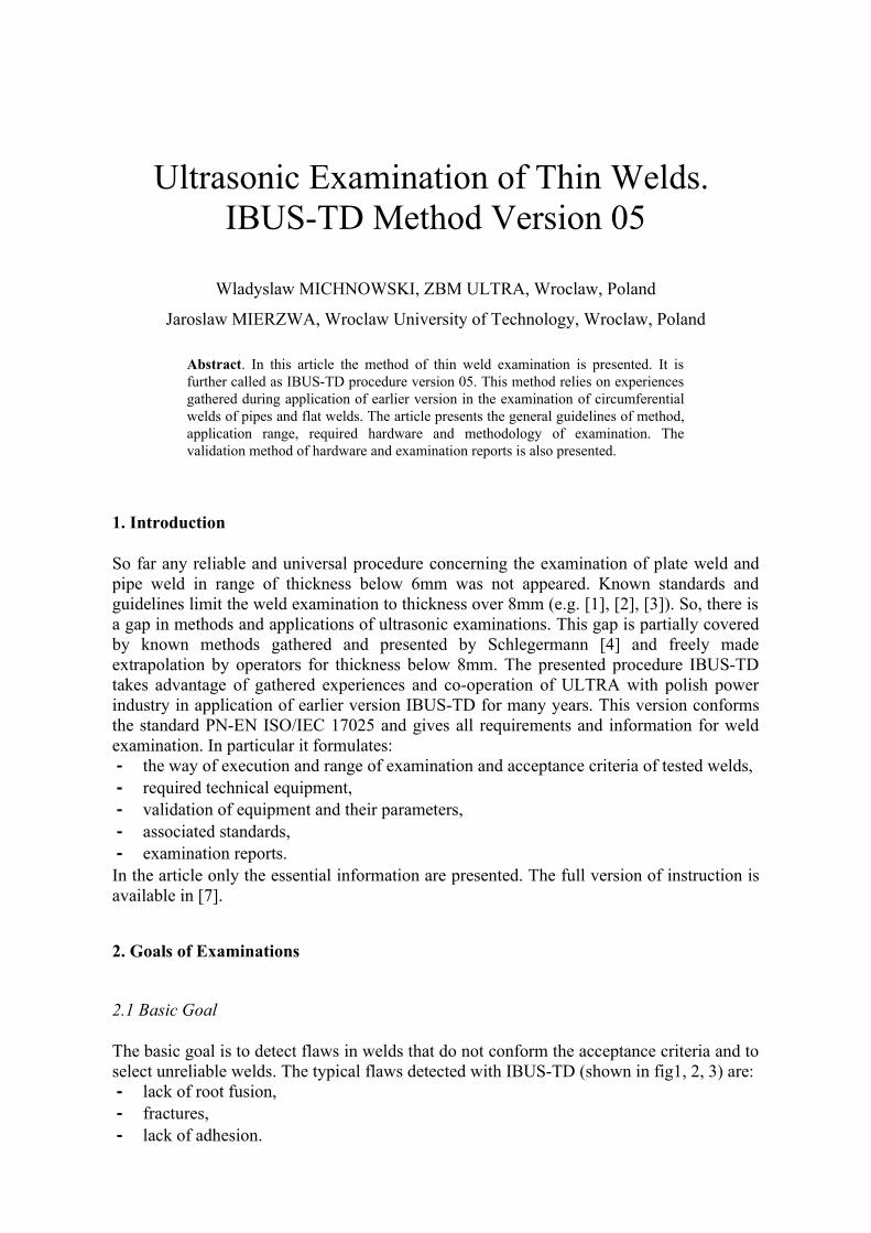
The basic goal is to detect flaws in welds that do not conform the acceptance criteria and to select unreliable welds. The typical flaws detected with IBUS-TD (shown in fig1, 2, 3) are:- lack of root fusion,- fractures,- lack of adhesion.
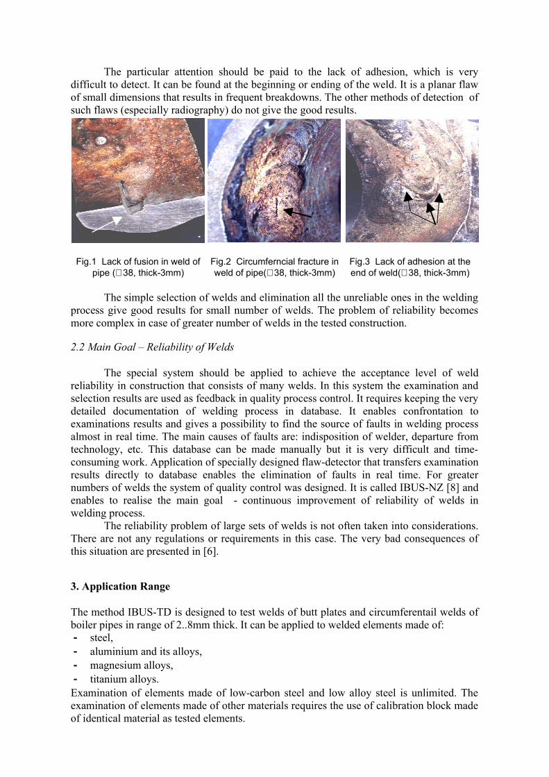
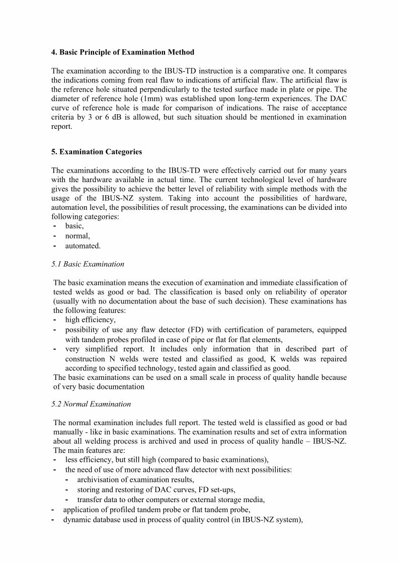
The particular attention should be paid to the lack of adhesion, which is very difficult to detect. It can be found at the beginning or ending of the weld. It is a planar flaw of small dimensions that results in frequent breakdowns. The other methods of detection of such flaws (especially radiography) do not give the good results.
Fig.1 Lack of fusion in weld of pipe (∅38, thick-3mm)
Fig.2 Circumferncial fracture in weld of pipe(∅38, thick-3mm)
Fig.3 Lack of adhesion at the end of weld(∅38, thick-3mm)
The simple selection of welds and elimination all the unreliable ones in the welding process give good results for small number of welds. The problem of reliability becomes more complex in case of greater number of welds in the tested construction.
2.2 Main Goal – Reliability of Welds
The special system should be applied to achieve the acceptance level of weld reliability in construction that consists of many welds. In this system the examination and selection results are used as feedback in quality process control. It requires keeping the very detailed documentation of welding process in database. It enables confrontation to examinations results and gives a possibility to find the source of faults in welding process almost in real time. The main causes of faults are: indisposition of welder, departure from technology, etc. This database can be made manually but it is very difficult and time-consuming work. Application of specially designed flaw-detector that transfers examination results directly to database enables the elimination of faults in real time. For greater numbers of welds the system of quality control was designed. It is called IBUS-NZ [8] and enables to realise the main goal - continuous improvement of reliability of welds in welding process.
The reliability problem of large sets of welds is not often taken into considerations. There are not any regulations or requirements in this case. The very bad consequences of this situation are presented in [6].
3. Application Range
The method IBUS-TD is designed to test welds of butt plates and circumferentail welds of boiler pipes in range of 2..8mm thick. It can be applied to welded elements made of:- steel,- aluminium and its alloys,- magnesium alloys,- titanium alloys.Examination of elements made of low-carbon steel and low alloy steel is unlimited. The examination of elements made of other materials requires the use of calibration block made of identical material as tested elements.
4. Basic Principle of Examination Method
The examination according to the IBUS-TD instruction is a comparative one. It compares the indications coming from real flaw to indications of artificial flaw. The artificial flaw is the reference hole situated perpendicularly to the tested surface made in plate or pipe. The diameter of reference hole (1mm) was established upon long-term experiences. The DAC curve of reference hole is made for comparison of indications. The raise of acceptance criteria by 3 or 6 dB is allowed, but such situation should be mentioned in examination report.
5. Examination Categories
The examinations according to the IBUS-TD were effectively carried out for many years with the hardware available in actual time. The current technological level of hardware gives the possibility to achieve the better level of reliability with simple methods with the usage of the IBUS-NZ system. Taking into account the possibilities of hardware, automation level, the possibilities of result processing, the examinations can be divided into following categories:- basic,- normal,- automated.
5.1 Basic Examination
The basic examination means the execution of examination and immediate classification of tested welds as good or bad. The classification is based only on reliability of operator (usually with no documentation about the base of such decision). These examinations has the following features:- high efficiency,- possibility of use any flaw detector (FD) with certification of parameters, equipped
with tandem probes profiled in case of pipe or flat for flat elements,- very simplified report. It includes only information that in described part of
construction N welds were tested and classified as good, K welds was repaired according to specified technology, tested again and classified as good.
The basic examinations can be used on a small scale in process of quality handle because of very basic documentation
5.2 Normal Examination
The normal examination includes full report. The tested weld is classified as good or bad manually - like in basic examinations. The examination results and set of extra information about all welding process is archived and used in process of quality handle – IBUS-NZ. The main features are:- less efficiency, but still high (compared to basic examinations),- the need of use of more advanced flaw detector with next possibilities:
- archivisation of examination results,- storing and restoring of DAC curves, FD set-ups,- transfer data to other computers or external storage media,
- application of profiled tandem probe or flat tandem probe,- dynamic database used in process of quality control (in IBUS-NZ system),
- automatically archived technical documentation and examinations results,- professional training of staff about IBUS-TD and IBUS-NZ instruction.
6. Hardware and Equipment
The hardware and equipment required for basic and normal examinations consists of:- flaw detector,- tandem probes and DAC curves,- water moistening system,- computer equipped with IBUS-PR,- calibration blocks.
6.1 Flaw Detector
The technical requirements for flaw detectors are imposed by examination category. For basic examination even analogue flaw detectors can be used. But in case of normal and automated examinations the flaw detector has to have the possibility to store and restore data i.e.:- storing and restoring of working parameters of flaw detector (range, gain, gate
parameters, etc.),- store the examination results and extra information concerning the examination:
- date and time of examination,- identifier of welder (name and surname for example),- identifier of examination person (name and surname for example),- identifier data of weld and group of weld,- the successive number of examination (control examination, repair),
- easy and fast transfer of examination results to host computer, - view and transfer of the examination results in real time.FD parameters should be confirmed with certificate according to EN12688-1 standard.
6.2 Calibration Blocks
There are two types of calibration blocs:- simple – for making DAC curve,- normal – for validation of probe parameters and control of parameters in examinations.
6.2.1 Simple Calibration Blocks
Examination person can make the simple calibration block by making the reference hole in currently tested part of plate or pipe or in place identical to currently tested one.
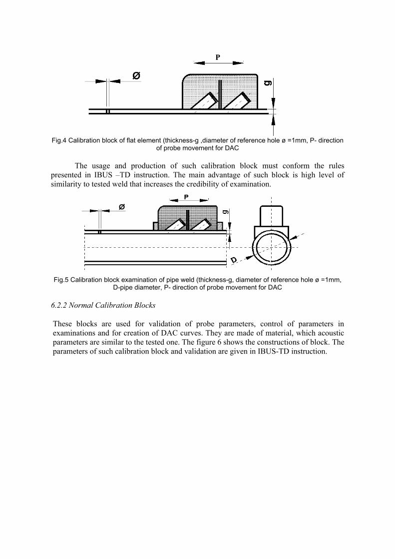
Fig.4 Calibration block of flat element (thickness-g ,diameter of reference hole ø =1mm, P- direction of probe movement for DAC
The usage and production of such calibration block must conform the rules presented in IBUS –TD instruction. The main advantage of such block is high level of similarity to tested weld that increases the credibility of examination.
Fig.5 Calibration block examination of pipe weld (thickness-g, diameter of reference hole ø =1mm, D-pipe diameter, P- direction of probe movement for DAC
6.2.2 Normal Calibration Blocks
These blocks are used for validation of probe parameters, control of parameters in examinations and for creation of DAC curves. They are made of material, which acoustic parameters are similar to the tested one. The figure 6 shows the constructions of block. The parameters of such calibration block and validation are given in IBUS-TD instruction.
P
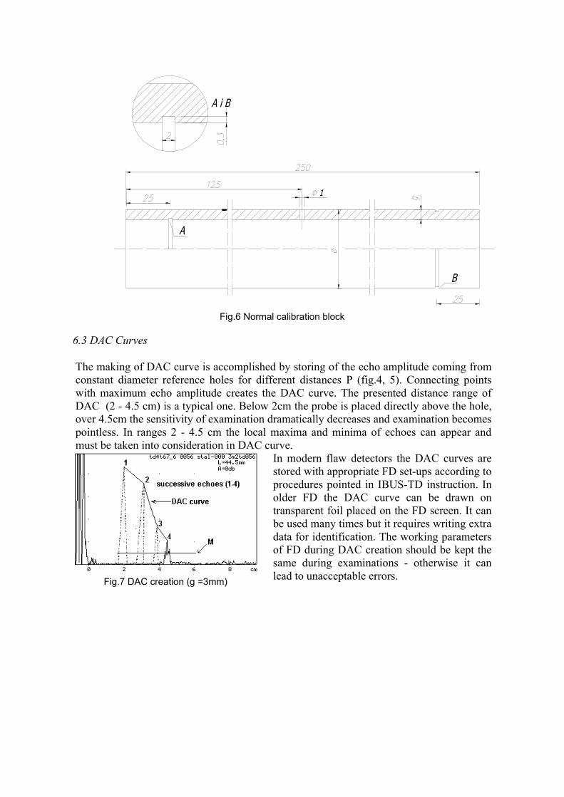
Fig.7 DAC creation (g =3mm)
Fig.6 Normal calibration block
6.3 DAC Curves
The making of DAC curve is accomplished by storing of the echo amplitude coming from constant diameter reference holes for different distances P (fig.4, 5). Connecting points with maximum echo amplitude creates the DAC curve. The presented distance range of DAC (2 - 4.5 cm) is a typical one. Below 2cm the probe is placed directly above the hole, over 4.5cm the sensitivity of examination dramatically decreases and examination becomes pointless. In ranges 2 - 4.5 cm the local maxima and minima of echoes can appear and must be taken into consideration in DAC curve.
In modern flaw detectors the DAC curves are stored with appropriate FD set-ups according to procedures pointed in IBUS-TD instruction. In older FD the DAC curve can be drawn on transparent foil placed on the FD screen. It can be used many times but it requires writing extra data for identification. The working parameters of FD during DAC creation should be kept the same during examinations - otherwise it can lead to unacceptable errors.
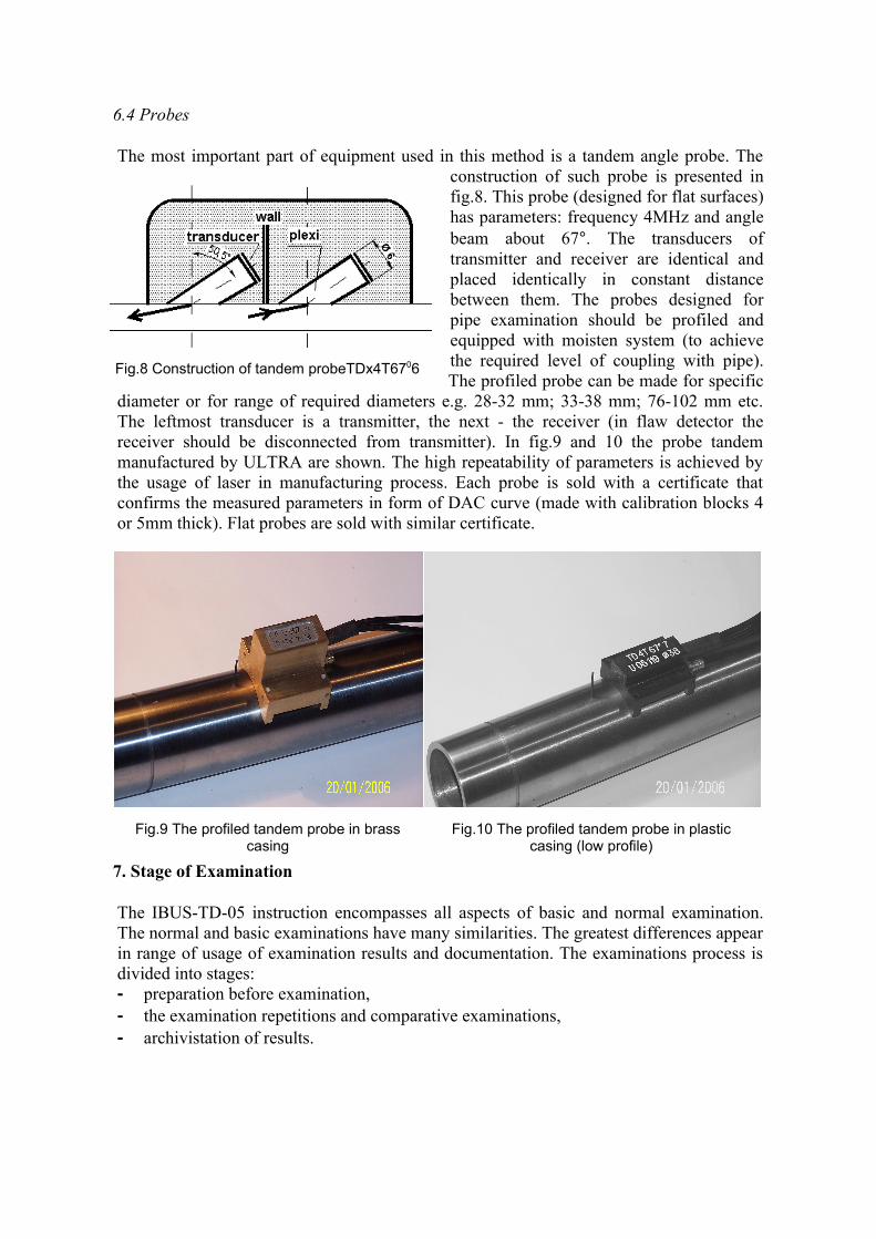
Fig.8 Construction of tandem probeTDx4T6706
6.4 Probes
The most important part of equipment used in this method is a tandem angle probe. The construction of such probe is presented in fig.8. This probe (designed for flat surfaces) has parameters: frequency 4MHz and angle beam about 67°. The transducers of transmitter and receiver are identical and placed identically in constant distance between them. The probes designed for pipe examination should be profiled and equipped with moisten system (to achieve the required level of coupling with pipe). The profiled probe can be made for specific
diameter or for range of required diameters e.g. 28-32 mm; 33-38 mm; 76-102 mm etc. The leftmost transducer is a transmitter, the next - the receiver (in flaw detector the receiver should be disconnected from transmitter). In fig.9 and 10 the probe tandem manufactured by ULTRA are shown. The high repeatability of parameters is achieved by the usage of laser in manufacturing process. Each probe is sold with a certificate that confirms the measured parameters in form of DAC curve (made with calibration blocks 4 or 5mm thick). Flat probes are sold with similar certificate.
7. Stage of Examination
The IBUS-TD-05 instruction encompasses all aspects of basic and normal examination. The normal and basic examinations have many similarities. The greatest differences appear in range of usage of examination results and documentation. The examinations process is divided into stages:- preparation before examination,- the examination repetitions and comparative examinations,- archivistation of results.
Fig.9 The profiled tandem probe in brass casing
Fig.10 The profiled tandem probe in plastic casing (low profile)
8. Preparation before Examination
Preparation before examination has crucial influence on efficiency and credibility of examination. It requires the preparation of description of tested object, assembling of equipment, gathering of examination staff, checking of object preparation to examination, and acceptation of executed preparation.
In case of normal examinations most of documentation and descriptions are made in electronic form.
9. Making Examinations
9.1 Probe Movements
During examination the operator should move probe forward and backward perpendicularly to the axle of the weld and join these moves with movement along the axle of the weld. These movements can be made quickly in sections but the full area of the weld must be examined many times.
During probe movements the FD screen should be observed and indications evaluated according to point 9.2.
9.2 Evaluation of Indications
The evaluation of indications is made according to the next rules:- indications with amplitude below DCA curve are acceptable,- indications with amplitude exceeding DAC curve are not acceptable,- a little deviation of +/-3dB is allowed.
10. Results of Examinations
The proper usage of examination results enables to achieve the main goal of examinations. This imposes the need (as a rule) of testing all welds in welds group by operators. It concerns to basic and normal examinations. Any departure from this rule disables the proper selection of unreliable welds and gives the lower reliability of the tested object and should be accepted by customers.
10.1 Results of Basic Examinations
In this type of examinations the overall result is to specify all unacceptable welds, repair of bad welds, testing of repaired welds and issue the certification. All exceptions i.e. the not tested welds should be specified and the reason for not testing justified. Customer should accept each exception in writing.
10.2 Results of Normal Examinations
In normal examination the results are transferred to host computer with database, which is the element of IBUS-NZ system. There are a few ways to transfer data:- manually via keyboard,- indirectly via the computer operator equipped with radio communication equipment,- directly - wireless and automatic transfer from FD to host computer,
The following data are always be transferred: number of weld, identifier of welder, identifier of examination person, result of examination (good/bad). With immediate transfer, the system enables not only to view the testing result but also enables to assess: the welders work, used technology, advance of reparation of object, etc. The detailed possibilities are presented in IBUS-NZ procedure. If the IBUS-NZ system is placed in network computer then the access to database is possible from many others computers (e.g. customers one).
11. Conclusions
Upon this article the next conclusions can be deducted:- the presented method of thin welds examination puts the possibilities of ultrasonic tests
into new dimension,- such examinations are essential and the lack of them can give serious and negative
consequences,- the presented method is complete and includes: methodology, technical equipment,
documentation and archivisation of examinations, and enables to find the reason of unreliable welds,
- the close relation of weld examination to reliability of whole construction gives the new parameter of its quality: the number of welds in construction. The analysis of influence of this parameter on reliability of whole construction is the basis of IBUS-NZ procedure, which combines the examination results with quality process control in real time,
- the new approach of combining weld examination results and problem of reliability of whole construction was (so far) underestimated and not noticed.
References
[1] Polish standard PN-89/M-70055/02[2] European standard EN-1712, EN-1714[3] ASME Section V Article 5[4] Schelgermann U. Ultrasonic examination of welded joints of small thickness, Seminary on NDT,
Zakopane 1998, Poland[5] European standard EN-12688-1[6] Barczyk J., Leszkowicz F., Michnowski W., System of high reliability in energy boilers, Dozor
Techniczny 4/92, Poland[7] Michnowski W., Mierzwa J., IBUS-TD procedure, www.ultrasonic.home.pl[8] Michnowski W., Mierzwa J., IBUS-NZ procedure, www.ultrasonic.home.pl