ultrasonic c-scan inspection of composite materials
TRANSCRIPT
Engineering Journal of Qatar University, Vol. 5, 1992, p. 201 -222
ULTRASONIC C-SCAN INSPECTION OF COMPOSITE MATERIALS
A. Fahr* and A. Y. Kandeil** *Structures and Materials Laboratory, Institute for Aerospace Research, National Research Council of
Canada, Montreal Road, Ottawa, Canada **Professor, Mechanical Engineering Department, Faculty of Engineering, Qatar University
Doha, Qatar (First Received June 1992; accepted in revised form October 1992)
ABSTRACT
Ultrasonic technique using an automated C-scan has been established as the primary inspection method for composite materials. In this paper, the principles of ultrasonic inspection, the type of defects that may be generated during fabrication and/or during service of fibre-reinforced composites and their detection using ultrasonic techniques are described. Emphasis is placed on the capabilities and limitations of ultrasonic techniques in testing composites. The material used in the present study was graphite/epoxy.
INTRODUCTION
Fibre reinforced composite materials are being used increasingly in many applications because they offer several unique advantages. Some of these advantages are, high strength-to-weight and stiffness-to-weight ratios in addition to good corrosion resistance. Furthermore, large structures can be fabricated from fewer components than would be the case in a corresponding metallic structure.
Since composites are inhomogeneous materials, the form of defects and their effect on mechanical performance is quite different and more complex than metallic materials. In general, composites do not accumulate damage via growth of a single flaw, but rather by initiation of a myriad of small matrix defects which ultimately lead to the development of delamination (1). For stiffness critical structures, this may be considered to be the end point of their useful life.
There are several non-destructive testing (NOT) techniques which are applicable to composite materials (2-4). These are used to quantify defects generated during fabrication or introduced in service. Ultrasonic technique is one of the most widely used methods which can give information on the size and location of defects. In addition, automated ultrasonic C-scan systems can provide safe, accurate and reliable inspections at high speed. Due to these advantages, the ultrasonic C-scan has been established as the primary inspection method for composite materials.
201

A. Fahr and A. Y. Kandeil
This paper provides an introduction to ultrasonic C-scan inspection techniques and their application to the detection and characterization of defects in composite materials. First, the principles of ultrasonic inspection are described. Then the types of defects that may be introduced into the composites during processing and/or during service are mentioned. Finally, some C-scan inspection results obtained from graphite epoxy laminates containing various types of flaws are presented. The bulk of the experimental work described in this review was carried out at the Structures and Materials Laboratory, Institute for Aerospace Research, National Research Council of Canada and the results have been published elsewhere (5). This paper is a concise summary of that work.
BASIC PRINCIPLES OF ULTRASONIC INSPECTION
1. Generation and Propagation of Ultrasonic Waves
Ultrasonic waves can be generated by piezoelectric transducers which convert an oscillating applied voltage into mechanical vibration in the MHz frequency range. This mechanical vibration is transmitted into the test material by means of a coupling medium such as water.
Propagation of ultrasonic waves in an elastic material is by displacement of material particles ( 6). The basic types of waves which propagate in the bulk of a material are longitudinal (compressional) and transverse (shear) waves. For longitudinal waves, the particles of the medium vibrates in the direction of propagation, while for transverse waves, the particles of the medium vibrate in a direction at right angles to the direction of propagation. The velocity of ultrasonic waves is dependent on the density and the stiffness of the material, longitudinal velocity being slightly less than twice the shear velocity. In composite laminates, generally, stiffness varies from one direction to another depending on fibre orientation. Thus, the sound velocity in composite laminates is different in different directions. Fig. 1 shows the longitudinal and shear wave velocities in graphite fibre/epoxy composites (6), indicating that ultrasonic waves propagate faster along the fibre direction.
2. Reflection and Refraction at Boundaries
When an ultrasonic wave encounters an interface between two materials, a portion of the energy is transmitted and a portion is reflected. The governing factors which determine the reflected proportion are the beam incident angle, wave velocity and material density. For plane waves at normal angles of incidence, the reflection and transmission coefficients are given respectively by (7):
Ir (Z2 - Z1)2 (1)
202

Ultrasonic C-Scan Inspection of Composite Materials
LONGITUDINAL OR COMPRESSIONAL WAVE 1.5
TRANSVERSE OR SHEAR WAVE
( 2)
Fig. 1: Ultrasonic velocities (mm/JJ.s) in a graphite/epoxy composite, Hercules AS/3501-6 (Reference 6).
where I;, I. and It represent the intensity of the incident, reflected and transmitted waves and z1 and z2 are the product of density and wave velocity in medium 1 and 2, respectively. This product is called the acoustic impedance of the material. If the acoustic impedance of a defect is equal to that of the host material (z1 = z2), the interface is non-reflective (ocr = 0) and thus the defect is undetectable in the reflection mode.
It is difficult to evaluate the acoustic impedance of a composite material because both density and wave velocity in the structure are changing from one point to another. However, the overall impedance in a certain fibre direction can be determined from the acoustic velocity in that direction and the overall density of the material. Table 1 provides the acoustic impedance of some materials of interest (8, 9) and the reflection and transmission coefficients of longitudinal waves travelling from a graphite epoxy laminate into a second material at normal angles of incidence.
When the ultrasonic beam impinges on an interface at an oblique angle, in addition to reflection, refraction and mode conversion also occur. In isotropic homogeneous materials, an incident compressional wave can produce two refracted
203

A. Fahr and A. Y. Kandeil
Table 1 Acoustic Impedance of Some Materials with Reflection and Transmission Coefficients for Longitudinal Plane Waves Travelling from Graphite/Epoxy
Laminate into these Materials at Normal Indicence.
Acoustic* Reflection Transmission Medium Impedance Coefficient Coefficient l05g cm-2 s-1
Air (void, delamination) 0.004 0.997 0.003
Water 1.48 0.283 0.717
Teflon 3.0 0.055 0.945 (artificial delamination)
Plexiglass 3.1 0.048 0.952
Ice 3.5 0.026 0.974
Epoxy resin ,2.7-3.6 0.045 0.955
Glass 114-15 0.248 0.752
Graphite/Epoxy 14-15 0.248 0.752 (Parallel to fibres) 4.4-5.3 0.0 1.0 (Perpendicular to fibres)
Aluminum 17.0 0.309 0.691
Titanium 27.3 0.487 0.513
Steel 46.0 0.655 0.345
*From References 8 and 9.
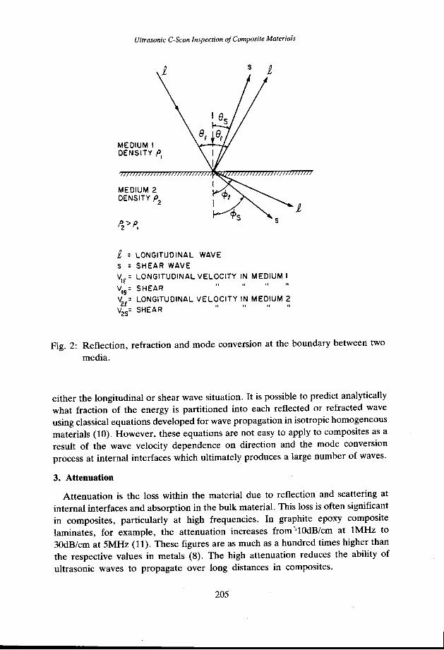
waves, longitudinal and shear, Fig. 2. The refraction angles are dependent on the incident angle and the acoustic velocities of the two media, as given by Snell's law:
v2 sin 6 = vl sin <!> (3)
where V is the appropriate longitudinal or shear velocity in material 1 or 2 respectively, and 6 is the angle of incidence and <!> is the angle of refraction for
204
Ultrasonic C-Scan Inspection of Composite Materials
MEDIUM I DENSITY PI
MEDIUM 2 DENSITY p
2
i, : LONGITUDINAL WAVE
s = SHEAR WAVE
s
s
V1R: LONGITUDINAL VELOCITY IN MEDIUM I
V : SHEAR " " " " IS
V21
= LONGITUDINAL VELOCITY IN MEDIUM 2 v25
= SHEAR " " " "
Fig. 2: Reflection, refraction and mode conversion at the boundary between two
media.
either the longitudinal or shear wave situation. It is possible to predict analytically what fraction of the energy is partitioned into each reflected or refracted wave using classical equations developed for wave propagation in isotropic homogeneous materials (10). However, these equations are not easy to apply to composites as a result of the wave velocity dependence on direction and the mode conversion process at internal interfaces which ultimately produces a large number of waves.
3. Attenuation
Attenuation is the loss within the material due to reflection and scattering at internal interfaces and absorption in the bulk material. This loss is often significant in composites, particularly at high frequencies. In graphite epoxy composite laminates, for example, the attenuation increases from ~lOdB/cm at lMHz to 30dB/cm at 5MHz (11). These figures are as much as a hundred times higher than the respective values in metals (8). The high attenuation reduces the ability of ultrasonic waves to propagate over long distances in composites.
205

TRANSDUCER
DELAYED TRIGGER
A. Fahr and A. Y. Kandeil
--d-WATER
- ~ __., r-:::::: 1::±
TEST PANEL
--===
REFLECTOR
GATE
Fig. 4: The reflector plate pulse-echo technique used for inspection of thin composite panels (d < 10>..) and a schematic of a typical oscilloscope view.
208
Ultrasonic C-Scan Inspection of Composite Materials
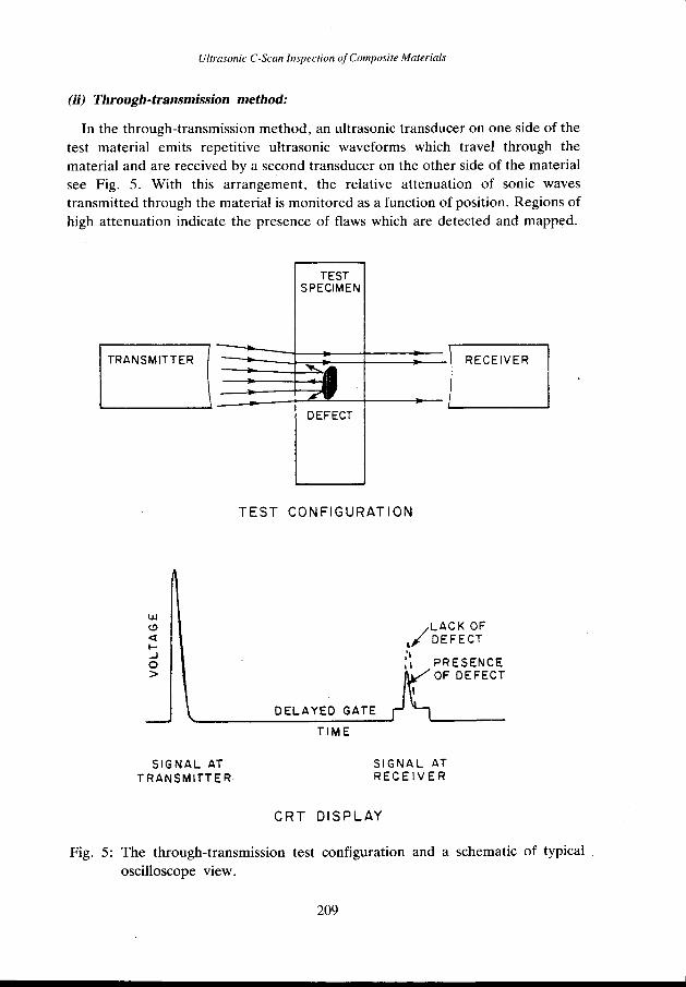
(ii) Through-transmission method:
In the through-transmission method, an ultrasonic transducer on one side of the test material emits repetitive ultrasonic waveforms which travel through the material and are received by a second transducer on the other side of the material see Fig. 5. With this arrangement, the relative attenuation of sonic waves transmitted through the material is monitored as a function of position. Regions of high attenuation indicate the presence of flaws which are detected and mapped.
LLI (!)
<t 1-..J 0 >
SIGNAL AT TRANSMITTER
TEST SPECIMEN
TEST CONFIGURATION
DELAYED GATE
TIME
LACK OF ,/DEFECT ,'I , 1 PRESENCE
OF DEFECT
SIGNAL AT RECEIVER
CRT DISPLAY
Fig. 5: The through-transmission test configuration and a schematic of typical oscilloscope view.
209

A. Fahr and A. Y. Kandeil
damage is obtained in this case. Alternatively, the time of travel of the pulse in the material can be monitored as a function of the position of the probe to provide flaw depth information. This technique is known as the time-of-flight method.
The C-scan is widely used for inspection of composite structures after fabrication to ensure high quality. For this purpose, the part is generally immersed in water to provide a uniform coupling for the transmission of sound waves between the transducers and the part. While total immersion in a water tank is often used in research laboratories for the inspection of composite penels, the technique has limited applicability to large structures due to factors such as the size of water tank required. The alternative approach is to use water jets or squirters instead of total immersion. In this approach, the ultrasonic beam is transmitted to the part through a water stream. It then traverses the part and travels through another water stream on the far side to the receiving transducer (15). C-scan system based on squirters are often used for inspection of large and complex components. For greater efficiency, the new C-scan systems employ computers which enable automatic scanning, data collection and analysis. Portable C-scan equipment with on-board computers are now available for in-service inspection of composite structures. These equipment use small frames for manual or automatic scanning of the probe and advanced image processing method for presentation of C-scan images.
DETECTION OF DEFECTS IN COMPOSITE LAMINATES USING ULTRASONIC C-SCAN
Flaws in composites are occasionally developed either during manufacturing or in service. The important fabrication defects in composite laminates are interlaminar voids and porosity, foreign inclusions, fibre mis-orientation, and resin rich or resin starved areas. The primary service-induced defects are delamination, fibre fracture and matrix cracks. These often occur together as the result of mechanical damage caused by impact, fatigue or overload.
In the following paragraphs the ultrasonic C-scan techniques used for the detection and characterization of major defects in composite laminates are described.
1. Inter laminar Voids and Porosity
When composite plies are assembled into a laminate, some amount of air may be trapped between the plies. Therefore, after the laminate is assembled, it is de bulked under vacuum to remove the entrapped air. However, in some cases, a small amount of air can remain trapped. During the curing process, this air fills spaces between plies and fibres and forms interlaminar voids or porosity. In certain situations, flaws of this type can be detected by ultrasonic C-scan although
212

Ultrasonic C-Scan Inspection of Composite Materials
individual pores cannot usually be resolved. The C-scan image of a composite laminate containing regions of high porosity is presented in Fig. 7. This panel was fabricated from 35 plies of graphite/epoxy prepreg material. Because the ultrasonic beam cannot resolve individual pores, the C-scan image of the cluster of porosity often appears as large void. However, the C-scan image of a void generally has a regular shape whereas the porosity image usually is more irregular.
2. Foreign Material Inclusions
The process of fabrication of composite materials involves the stacking of several layers of composite plies (prepregs) on top of each other. In this process a number of separating and packaging materials such as paper, nylon, teflon, fibre glass cloth, etc. must be removed. Although care is taken to ensure proper disposal, occasionally some of these foreign materials is inadvertently left in a laminate. Many of these materials are detectable by ultrasonic C-scan, either because they do not bond to the laminate or have different acoustic impedance and attenuation from the composite laminate. Some of them, however, do adhere to the epoxy matrix and have acoustic properties similar to the host composite material. These can be very difficult to find with C-scan techniques.
To investigate the detectability of inclusions in composites, a panel was made from 10 plies of graphite/epoxy prepreg fabric with foreign materials extensively
Fig. 7: A C-scan image of a unidirectional graphite/epoxy panel showing clusters of porosity.
213

A. Fahr and A. Y. Kandeil
used in the handling and fabrication of composites and included paper, release film, bagging material, teflon sheets (0.025mm and 0.075mm thickness) peel ply and release agents. Fig. 8a shows the placement of these materials.
The C-scan results, as shown in Fig. 8b, revealed only the teflon and the paper inclusions. Although the sensitivity of the inspection was optimized by using the pulse-echo reflector plate method and a highly sensitive transducer (10 MHz, focused) with high threshold levels, other inclusions were not easily detectable.
3. Fibre Mis-orientation
Composite laminates generally consists of several layers of prepreg material stacked in different order and orientation to achieve the required stiffness and strength. Mis-orientation or mis-order in one or more plies may have significant adverse effects on the mechanical performance of the composite structure. Therefore, nondestructive examination of the laminate stacking order and orientation is important in critical applications.
With ultrasonic C-scan it is very difficult to obtain direct information on the number of layers or their lay-up order. However, there are methods for
0 0 0 0 0
., .
0 0 0 0 (a)
Fig. 8a: A graphite/epoxy test panel containing various types of foreign inclusions.
1. SILICON RELEASE AGENT 2. PEEL PLY (0.075 mm)
3. TEFLON TAPE (0.075 mm) 4. RELEASE FILM (0.025 mm NYLON) 5. PAPER SHEET (0.075 mm)
6. RELEASE ALL SPRAY 7. OIL-BASED RELEASE FILM 8. TEFLON TAPE (0.025 mm) 9. BAGGING MATERIAL (0.075 mm NYLON)
Fig. 8b: A C-scan image of the above panel showing only teflon and paper inclusions. Areas with above the average resin content appear as white. Transducer: 10 MHz, 10 em focal length.
214

Ultrasonic C-Scan Inspection of Composite Materials
determining the orientation of plies. These methods are based on the imaging of ultrasonic backscattered (1) or transmitted energy (16) when the beam is incident on the surface of the composite laminate at an oblique angle. In the case of backscatting, for example, energy is returned to the transducer only when the ultrasonic beam is close to being perpendicular to the fibre direction. A C-scan determination of fibre orientation can be performed by rotating the test panel on a turntable (polar scnanning) while the transducer is indexed in the radial direction as shown in Fig. 9a to monitor the ultrasonic backscatting from fibres. Fig. 9b shows a
' I
0 . ' • ·, '. ~-. "1··:: .. . ": ; :·-·. . ·. ·.: ...... : < -..:~·,. ..... ~· '..!r ·• ·, •• ,... . .. f ·~-. :. '
FIBRES
(a)
90
' ·- . < ---
1'\ ,. l. .... 0
_ _;_-::;.:.,.::_. • ..::.··..:.4-:;..:..:....!:!-A .......... ~~--.-:-rr. ~ .. :v:;-;7,T., ,"':', """: •. ~...--- 0 . '
(b)
Fig. 9a: Polar C-scan test configuration used to monitor fibre backscattering and to determine the orientation of plies.
Fig. 9b: A polar C-scan image of graphite/epoxy panel containing plies in the ( ±45°' 90°' 0°)S configuration showing fibre orientation.
215
A. Fahr and A. Y. Kandeil
polar C-scan of a graphite/epoxy laminate containing plies in a +45, +90, 0, -90, -45° configuration and indicates the true orientation of the plies. This polar image indicates that the 0 and 90° plies in the panel are not quite perpendicular as they were intended to be.
In addition to fibre orientation, the relative intensity of the polar C-scan gives some indication of the depth of plies of specific orientation since the scattering from inner plies is weaker than from outer plies due to acoustic attenuation effects. The attenuation effects limits the applicability of backscattering methods to composite laminates of less than 1 em in thickness.
4. Resin Rich Areas and Resin Starvation
Localized resin rich areas may occur at sharp bends or corners of a composite structure where resin extraction is difficult. Unlike the majority of defects, resin build-up in composites does not create defined boundaries that reflect the acoustic beam. Furthermore, the acoustic attenuation in resin is lower than in the finished composite, so that the transmitted acoustic intensity through resin rich areas is higher than through the base material and most other defects. Thus, resin rich areas are not often detectable at threshold levels set for other flaws. To detect resin rich areas, the threshold must be set at a level corresponding to the average attenuation for the test material and the flaw gate set to record echoes which exceed this threshold. Fig. 8b shows areas with above average resin content which appear as white on the C-scan image.
In contrast, resin starvation is easy to pick up in both the pulse-echo and the through-transmission modes. Lack of resin produces an image on the C-scan which is very similar to that produced by clusters of porosity and voids as illustrated in Fig. 10 for a graphite/epoxy composite laminate.
5. Delamination
Delamination or separation of plies in a composite laminate is caused by mechanical impact, overloading or fatigue and often involves the fibre breakage and matrix cracking.
Delamination is easily detectable by C-scan with both through-transmission and pulse-echo techniques. The C-scan image in Fig. 11 illustrates delamination damage in a composite laminate caused by drop-weight impact. This panel was made of 48 plies of graphite/epoxy prepreg in (±45, 90, 0°) configuration. As seen in Fig. 11, the C-scan gives an overall view of the planar extent of damage but does not identify the depth profile or location of the defect. Depth information can be obtained by using A-scan, B-scan, or time-of-flight methods. Fig. 12 illustrates the B-scan and time-of-flight C-scan images of an impact damage in carbon fibre composite laminate. In Fig. 12a the cross sectional view of the impact damage along
216

Ultrasonic C-Scan Inspection of Composite Materials
~REFERENCE TAPES
i
~ ,·'
Fig. 10: A C-scan image of a resin starved area in a graphite/epoxy laminate.
- ,&
:
Fig. 11: A C-scan image of a graphite/epoxy composite laminate (48 plies in [±45°, 90°, 0°]S configuration) subjected to a drop-load impact. Impact energy: 17KN. Image is full size.
217

A. Fahr and A. Y. Kandeil
an inspection line is shown while in Fig.l2b the depth of delaminations is indicated by various colours or shadings in the time-of-flight C-scan image. Such measurements are only possible where the thickness of the panel is several times larger than the ultrasonic wavelength. Fibre breakage or matrix cracking is not easily detectable in this way. However, such defects affect the overall C-scan image. The
( b )
Fig. 12a: A B-scan image showing the cross-sectional view of an impact damage.
Fig. 12b: A time-of-flight C-scan image of the imapct damage, depth of delaminations is indicated by different colour shadings.
218

Ultrasonic C-Scan Inspection of Composite Materials
next paragraph describes a technique that may be useful for detecting defects of this type.
6. Fibre Fracture and Matrix Cracking
Detecting fibre fracture and matrix cracking is very difficult when using conventional (normal beam) ultrasonic C-scan methods, since these techniques are only capable of discerning damage in a plane perpendicular to the beam direction. However, techniques based on ultrasonic backscattering can be used (1, 17) to detect cracks in composites. As mentioned earlier in this section, ultrasonic backscattering measurements are usually made with the beam entering the material at an angle other than normal to the surface, see Fig. 9a. In this configuration, fibres will always return some energy to the transducer but cracks, which are strong reflectors, will produce signals which are generally larger than those from fibres. Therefore, by properly setting the threshold levels, backscattered echoes from cracks can be differentiat~d from those from fibres. Fig. 13 shows the backscattered C-scan results obtained from a panel containing 10 plies of unidirectional graphite/epoxy alllayed up in the same direction. The panel had a crack running along the fibre direction and both the fibre direction and the crack were detected using the polar C-scan and a 10 MHz focused transducer placed at around20° with respect to the normal to the test panel. This angle was found to be nearly optimum in terms of the intensity of the crack echo compared to the backscattered fibre signal.
CONCLUSIONS
Ultrasonic C-scan techniques can be utilized to detect and locate fabrication as well as service-induced defects in composite materials. The choice of the inspection and presentation techniques depends on the test material, geometry, the type of defects present and the information required. Voids, porosity, some inclusions, resin starvation and delamination can be easily detected and mapped using the pulse-echo or through-transmission methods. Fibre orientation and mis-alignment can be detected by using backscattering techniques with a polar C-scan. Backscattering method is also applicable to the detection of relatively large matrix cracks. However, microcracks in the matrix or breakage of individual fibres are below the detection limit of the conventional ultrasonic methods. Also, foreign inclusions which bond into laminates and have similar acoustic properties are not easily detectable using ultrasonic techniques.
Ultrasonic techniques can also reveal information on the size, location and sometimes types of defects. C-scan images obtained using amplitude of ultrasonic echoes provide a planner view of material defects but do not reveal the depth profile of flaws. Depth information can be obtained using time-of-flight C-scan method.
219

Ultrasonic C-Scan Inspection of Composite Materials
ACKNOWLEDGEMENTS
Specimens used in this study were fabricated and tested at the Structures and Materials Laboratory, Institute for Aerospace Research, National Research Council of Canada. The authors would like to thank the contributions of Mr. C. Chapman, Dr. A.M. Charlesworth, Dr. W. Wallace, Mr. S. Lee and Mr. R.E. Scott of the NRC Structures and Materials Laboratory.
REFERENCES
1. Bar-Cohen Y. and Crane R.L., 1982, Subcritical Flaws in Composites,
Acoustic-Backscattering Imaging of Mat. Eval. 40, p. 970.
2. Matzkanin G.A., 1982, Nondestructive Evaluation of Fibre Reinforced Composites , Publication NTIAC-82-1, Vol. 1, Southwest Research Institute.
3. Sendeckyj G.P., 1983, NDE Techniques for Composite Laminates , AGARD Conf. Proc. No. 355 on Characterization, Analysis and Significance of Defects in Composite Materials, held in London, UK.
4. Sturrock W.R., 1983, Application of Ultrasonic Inspections to CF-18 Structures , Paper No. 23, DREP Special Report 83-1, Vol. 2, Proc. of DND Composite Materials Workshop.
5. Fahr A. and Charlesworth A.M., 1986, An Introduction to the Ultrasonic C-scan Inspection of Advanced Composite Materials , LTR-ST-1602, NRC-NAE Publication.
6. Sturrock W.R., 1982, Ultrasonic Evaluation of Graphite/Epoxy Composite Laminates , Proc. of Conf. on Advanced NDE Technology Sponsored by Industrial Materials Research Institute, Montreal, IGM 82-000-059, p. 37.
7. Felipczynski L., Pawlowski Z. and Wehr J,, 1966, Ultrasonic Methods of Testing Materials , Butterworth, London, p. 5.
8. Krautkramer J, and Krautkramer H., 1977, Ultrasonic Testing of Materials , Second Ed., Springer-Verlag, New York.
9. Sturrock W.R. and Greenwood B.W., 1983, Evaluation of the 'Bondascope 2100' for the Inspection of CF-18 Bonded Structures , ATA Nondestructive Testing Forum, Air Transport Association, Kansas City.
10. Auld B.A., 1973, Acoustic Fields and Waves in Solids Vol. 1, John Wiley & Sons, New York.
221

A. Fahr and A. Y. Kandeil
11. Verette R.M., 1975, Temperature/Humidity Effects on the Strength of Graphite/Epoxy Laminates , AIAA Paper No. 75-1011, p. 1.
12. Collins R.M., 1981, NDE Chronology of Advanced Composites at Grumman Aerospace , Mat. Eval. 39.
13. Iddings F.A., 1985, Composites , Materials Evaluation, No. 4.
14. McMaster R.C., 1959, Nondestructive Testing Handbook , Vol. II, 43, 48-49. The Ronald Press Company, New York.
15. Jones T.S., 1984, A Cost Effective Approach to Reliable Inspection of Composites using the Automated Ultrasonic Scanning System . Proc. of a Workshop on Failure Modes and NDE of Composites, held at the Royal Naval Eng. College, Manadon, Plymouth, U.S.A.
16. Van Dreumel W.H.M. and Speijer J.L., 1981, Nondestructive Composite Laminate Characterization by Means of Ultrasonic Polar Scan , Mat. Eva!. 39, p. 922.
17. Moran T.J., Crane R.L. and Andrews R.J., 1985, High Resolution Imaging of Microcracks in Composites , Mat. Eva!. 43, p. 536.
222