ultra-high rockfill dam with combination of the reinforced ...81)/14.pdf · ultra-high rockfill dam...
TRANSCRIPT
Инженерно-строительный журнал, № 5, 2018
Саинов М.П., Сорока В.Б. Сверхвысокая каменно-набросная плотина с комбинацией железобетонного экрана и глиноцементобетонной диафрагмы // Инженерно-строительный журнал. 2018. № 5(81). С. 135–148.
doi: 10.18720/MCE.81.14
Ultra-high rockfill dam with combination of the reinforced concrete face and clay-cement diaphragm
Сверхвысокая каменно-набросная плотина с комбинацией железобетонного экрана и глиноцементобетонной диафрагмы
M.P. Sainov*, V.B. Soroka, National Research Moscow State Civil Engineering University, Moscow, Russia
Канд. техн. наук, доцент М.П. Саинов*, студент В.Б. Сорока, Национальный исследовательский Московский государственный строительный университет, Москва, Россия
Key words: rockfill dam; reinforced concrete face; cutoff wall slurry trench; stress-strain state; numerical modeling
Ключевые слова: каменно-набросная плотина; железобетонный экран; стена в грунте; напряжённо-деформированное состояние; численное моделирование
Abstract. The article deals with design validation of a new type of an embankment dam structural design, i.e. rockfill dam with combination of two types of non-soil seepage-control elements – a reinforced concrete face (in the dam upper part) and a clay-cement diaphragm made of bored piles (in the dam lower part). The dam of the considered design has a number of advantages over classical structural design of concrete faced rockfill dam (CFRD). First of all, conjugation of the seepage-control element with rock foundation does not require arrangement of a pit. Secondly, repairs of the dam lower part may be carried out by arrangement of a grout curtain. But the most important advantage of this design is more favorable conditions of the reinforced concrete operation, i.e. the face is subject to not tensile, but compressive longitudinal force. This decreases the risk of cracking in the face. Design validation of this structural design was conducted on the example of a 235 m high dam. Numerical modeling of the dam stress-strain state (SSS) was performed with consideration of construction and loading sequence, as well as with consideration non-linearity of rockfill deformation. Impact of four main factors on the dam SSS was studied: rockfill deformation, clay-cement deformation, diaphragm height and reinforced concrete thickness. Several alternatives of the dam design parameters were considered. Design of the numerical experiment was conducted by the method of factor analysis. This permitted revealing the impact of the considered factors on the dam SSS, as well as solving the problem on optimization of the dam structural solution. It was revealed that for providing the necessary level of the dam design safety the rockfill deformation modulus should be at least 250 MPa, and the diaphragm should be made of plastic clay-cement concrete. More favorable turned to be the case when the diaphragm height is 20 m but not 35 m.
Аннотация. Статья посвящена расчётному обоснованию нового типа конструкции грунтовой плотины – каменно-набросной плотины с комбинацией двух типов негрунтовых противофильтрационных элементов – железобетонного экрана (в верхней части плотины) и глиноцементобетонной диафрагмы, устроенной из буронабивных свай (в нижней части плотины). Плотина рассматриваемой конструкции имеет ряд преимуществ перед классической конструкцией каменно-набросной плотины с железобетонным экраном. Во-первых, для сопряжения противофильтрационного элемента со скальным основанием не требуется устройство котлована. Во-вторых, ремонт нижней части плотины может быть осуществлён путём создания инъекционной завесы. Но самым важным преимуществом данной конструкции является более благоприятные условия работы железобетонного экрана – экран испытывает не растягивающее, а сжимающее продольной усилие. Это снижает риск образования в экране трещин. Расчётное обоснование конструкции проводилось на примере плотины высотой 235 м. Численное моделирование напряжённо-деформированного состояния плотины велось с учётом последовательности её возведения и нагружения, а также с учётом нелинейности деформируемости каменной наброски. Было исследовано влияние на НДС плотины четырёх основных факторов: деформируемость каменной наброски, деформируемость глиноцементобетона, высота диафрагмы и толщина
135
Magazine of Civil Engineering, No. 5, 2018
Sainov, M.P., Soroka, V.B. Ultra-high rockfill dam with combination of the reinforced concrete face and clay-cement diaphragm. Magazine of Civil Engineering. 2018. 81(5). Pp. 135–148. doi: 10.18720/MCE.81.14.
железобетонного экрана. Рассматривалось несколько вариантов параметров конструкции плотины. Планирование численного эксперимента проводилось методом факторного анализа. Это позволило выявить влияние рассматриваемых факторов на напряжённо-деформированное состояние плотины, а также решить задачу об оптимизации конструктивного решения плотины. Было выявлено, что для обеспечения необходимого уровня надёжности конструкции плотины модуль деформации каменной наброски должен быть не ниже 250 МПа, а диафрагма должна выполняться из пластичного глиноцементобетона. Более предпочтительным оказался случай, когда высота диафрагмы составляет 20 м, а не 35 м. По результатам исследования можно сделать вывод, что рассмотренная конструкция каменно-набросной плотины с составным негрунтовым противофильтрационным элементом является хорошей альтернативой для классической конструкции грунтовой плотины с железобетонным экраном.
1. Introduction There are cases when the most feasible type of the dam is a rockfill dam with a non-soil seepage-
control element. Namely, the dams of this type are feasible for construction of projects in Siberia. Severe climatic conditions of Siberia hinder proper placement of concrete and clayey soils in the dam body, therefore, construction of concrete and rockfill dams in these conditions becomes ineffective.
However, the projects to be constructed in Siberia are as a rule high-head projects. This factor limits the types of non-soil seepage-control elements which may be used in an embankment dam. At present the only type of non-soil seepage-control element which is used in ultra-high embankment dams is a reinforced concrete face (RCF). To date a vast experience has been gained in construction of this type of dams; the theory of their designing was elaborated. In the world at least 6 CFRDs were constructed with height more than 200 m. The highest is Shuibuya dam in China with height 233 m [1].
But CFRD have serious disadvantages. At many ultra-high CFRDs emergency situations took place and were connected with formation of cracks in RCF [2–9]. Therefore, there is an urgent issue regarding improvement of dam designs of this type. Some researchers propose different refinements of the design and methods of CFRD construction [10–14]. However, by the results of our studies [15], various refinements of the classical CFRD design does not permit reaching the guaranteed level of safety. This is connected with a characteristic feature of their SSS: at the dam body deformations the longitudinal tensile force appears in the RCF lower part, which results in formation of cracks in the face. Therefore, it is necessary to search for other ways of refining structural designs of ultra-high embankment dams with RCF.
One of such ways is use of the seepage-control element of combined design consisting of two elements: RCF and clay-cement diaphragm (CCCD). We proposed this type of a dam earlier [16, 17] as an alternative to classical structural design of CFRD. The only example of a real dam with a combination of RCF and CCCD is the Hengshan Dam in China [18]. This dam is the result of reconstruction of the dam with the core in order to increase its height. One of the advantages of the dam structural design is possibility of its construction without a pit, without arrangement of protective cofferdams.
Our design studies [16, 17] showed that the proposed structural design is more efficient than the classical one. In this design RCF is not subject to tensile longitudinal force but is in compressive state. Besides, we studied the possibilities of using the combined structural design of the seepage-control element in ultra-high dams also [17]. It was revealed that in ultra-high dams the SSS of the seepage-control elements may be unfavorable and may not meet the standard requirements:
• Compressive stresses in RCF may exceed ultimate compressive strength of concrete, • Bending deformations may lead to appearance of tensile stresses in RCF, diaphragm, to
formation of cracks in it. Nevertheless, it was shown that correct selection of structural parameters of a rockfill dam with
combination of seepage-control elements may be sufficiently efficient. For example, compressive stresses in RCF may be decreased due to increase of its thickness and bending deformations of seepage-control elements may be minimized by decreasing rockfill deformation. At the same time the deformation characteristics of the diaphragm materials have ambiguous impact on the structure efficiency. Decrease of the diaphragm material modulus of deformation may both decrease and increase of RFC bending deformations. Therefore, there appeared a necessity in formulation of recommendations for selection of the dam parameters with combination of RCF and CCCD.
This article deals with the results of solving the problem on structural optimization of a rockfill dam with combination of RCF and CCCD. The study was conducted on the example of a 235 m high dam (Figure 1). In the upper part of the dam the seepage-control element is presented by a RCF. Its thickness at the dam crest is 0.5 m and it increases as it is deepened below the upstream level. The dam lower part
136

Инженерно-строительный журнал, № 5, 2018
Саинов М.П., Сорока В.Б. Сверхвысокая каменно-набросная плотина с комбинацией железобетонного экрана и глиноцементобетонной диафрагмы // Инженерно-строительный журнал. 2018. № 5(81). С. 135–148.
is a cofferdam with a seepage-control element presented by CCCD. The CCCD thickness was adopted to be rather large (1.8 m) in order to provide the seepage strength of clay-cement concrete. The diaphragm of such thickness may be constructed by the “slurry trench” method of two rows of bored piles located in a checkered order.
It was assumed that the dam body was made of rock muck, the diaphragm of gravel-sand mix. Conjugation of the RCF with the diaphragm was provided through the reinforced concrete gallery (Figure 2). RCF and the concrete gallery are separated from each other by a perimeter joint. Conjugation of the gallery with the diaphragm is also envisaged to be flexible; a cavity is provided between them which will be filled with watertight “soft” material (Figure 2).
Figure 1. Layout of a rockfill dam with combined seepage-control element:
1 – reinforced concrete face; 2 – under-face zone; 3 – protection shell; 4 – concrete gallery; 5 – clay-cement diaphragm; 6 – gravel-sand core; I, II, III, IV – dam construction stages
Figure 2. Layout of the interface between the seepage-control elements:
1 – reinforced concrete face; 2 – under-face zone; 3 – material of protection shell; 4 – reinforced concrete gallery; 5 – clay-cement diaphragm ; 6 – gravel-sand core; 7 – rockfill;
8 – perimeter joint; 9 – foreshaft; 10 – cavity.
2. Methods Studies of the dam structure efficiency with combination of seepage-control elements were
conducted with the aid of numerical modeling of the stress-strain state (SSS) by finite element method (FEM). During studies consideration was made of rockfill deformation non-linearity, non-linearity of contacts behavior between the elements of the structure, construction and loading sequence of the structure.
Beside the dam the model of the structure included a limited rock mass foundation under it. During analyses consideration was made of materials dead weight, US and DS hydrostatic water pressure and weighing water action on the upstream shell soil at the reservoir impoundment.
For description of soil deformation non-linearity the use was made of the soil model proposed by Professor L.N. Rasskazov [19]. At description of the contacts behavior its possible opening and sliding along it was taken into account. Coulomb-Mohr strength condition was used as the condition of shear strength failure.
Four construction and loading stages were envisaged. At the initial stage the upstream cofferdam is constructed. Then CCCD is provided in the gravel-sand core, and a reinforced concrete gallery above it. Then the dam of the first stage is constructed with RCF to el. 80 m, and the reservoir is impounded to el.73 m. And then gradually stages II, III, IV are constructed and the reservoir is impounded to FSL 230 m.
137
Magazine of Civil Engineering, No. 5, 2018
Sainov, M.P., Soroka, V.B. Ultra-high rockfill dam with combination of the reinforced concrete face and clay-cement diaphragm. Magazine of Civil Engineering. 2018. 81(5). Pp. 135–148. doi: 10.18720/MCE.81.14.
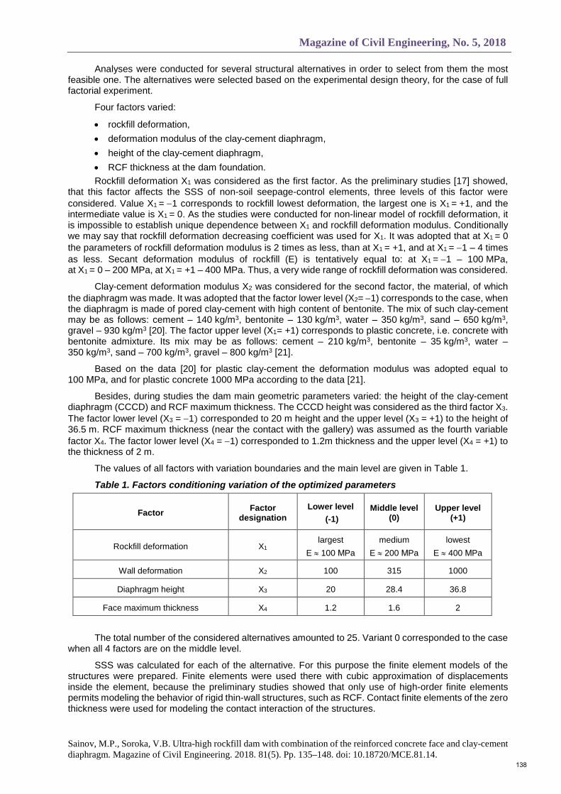
Analyses were conducted for several structural alternatives in order to select from them the most feasible one. The alternatives were selected based on the experimental design theory, for the case of full factorial experiment.
Four factors varied:
• rockfill deformation, • deformation modulus of the clay-cement diaphragm, • height of the clay-cement diaphragm, • RCF thickness at the dam foundation. Rockfill deformation X1 was considered as the first factor. As the preliminary studies [17] showed,
that this factor affects the SSS of non-soil seepage-control elements, three levels of this factor were considered. Value X1 = −1 corresponds to rockfill lowest deformation, the largest one is X1 = +1, and the intermediate value is X1 = 0. As the studies were conducted for non-linear model of rockfill deformation, it is impossible to establish unique dependence between X1 and rockfill deformation modulus. Conditionally we may say that rockfill deformation decreasing coefficient was used for X1. It was adopted that at X1 = 0 the parameters of rockfill deformation modulus is 2 times as less, than at X1 = +1, and at X1 = −1 – 4 times as less. Secant deformation modulus of rockfill (E) is tentatively equal to: at X1 = −1 – 100 MPa, at X1 = 0 – 200 МPa, at X1 = +1 – 400 МPa. Thus, a very wide range of rockfill deformation was considered.
Clay-cement deformation modulus X2 was considered for the second factor, the material, of which the diaphragm was made. It was adopted that the factor lower level (X2= −1) corresponds to the case, when the diaphragm is made of pored clay-cement with high content of bentonite. The mix of such clay-cement may be as follows: cement – 140 kg/m3, bentonite – 130 kg/m3, water – 350 kg/m3, sand – 650 kg/m3, gravel – 930 kg/m3 [20]. The factor upper level (X1= +1) corresponds to plastic concrete, i.е. concrete with bentonite admixture. Its mix may be as follows: cement – 210 kg/m3, bentonite – 35 kg/m3, water – 350 kg/m3, sand – 700 kg/m3, gravel – 800 kg/m3 [21].
Based on the data [20] for plastic clay-cement the deformation modulus was adopted equal to 100 МPa, and for plastic concrete 1000 МPa according to the data [21].
Besides, during studies the dam main geometric parameters varied: the height of the clay-cement diaphragm (CCCD) and RCF maximum thickness. The CCCD height was considered as the third factor X3. The factor lower level (X3 = −1) corresponded to 20 m height and the upper level (X3 = +1) to the height of 36.5 m. RCF maximum thickness (near the contact with the gallery) was assumed as the fourth variable factor X4. The factor lower level (X4 = −1) corresponded to 1.2m thickness and the upper level (X4 = +1) to the thickness of 2 m.
The values of all factors with variation boundaries and the main level are given in Table 1.
Table 1. Factors conditioning variation of the optimized parameters
Factor Factor designation
Lower level (-1)
Middle level (0)
Upper level (+1)
Rockfill deformation X1 largest
E ≈ 100 МPa medium
E ≈ 200 МPa lowest
E ≈ 400 МPa
Wall deformation X2 100 315 1000
Diaphragm height X3 20 28.4 36.8
Face maximum thickness X4 1.2 1.6 2
The total number of the considered alternatives amounted to 25. Variant 0 corresponded to the case when all 4 factors are on the middle level.
SSS was calculated for each of the alternative. For this purpose the finite element models of the structures were prepared. Finite elements were used there with cubic approximation of displacements inside the element, because the preliminary studies showed that only use of high-order finite elements permits modeling the behavior of rigid thin-wall structures, such as RCF. Contact finite elements of the zero thickness were used for modeling the contact interaction of the structures.
138

Инженерно-строительный журнал, № 5, 2018
Саинов М.П., Сорока В.Б. Сверхвысокая каменно-набросная плотина с комбинацией железобетонного экрана и глиноцементобетонной диафрагмы // Инженерно-строительный журнал. 2018. № 5(81). С. 135–148.
In the dam structure finite element model with the diaphragm height 35 m the number of finite elements amounted to 1040, and with 20 m diaphragm height – 1032. The number of freedom degrees in the structure models was 1057 and 1053 respectively.
Analyses of the dam structure alternatives SSS were conducted with the aid of the software NDS_N, worked out by M.P. Sainov, ph.dr. (tech.sc.) [22].
3. Results and Discussion Figures 2–5 shows the results of analyses for one of the structural alternatives (var. 0), where the
28.4 m high diaphragm is made of clay-cement with E = 315 МPa. In this alternative the rockfill deformation corresponds to X1 = 0.
By the results of analyses as of the moment of completion of the reservoir impoundment the maximum construction settlement of the dam is 160 cm. The zone of maximum dam settlements is located in the center of rockfill, because these settlements were determined for the case of the dam body layered construction. Maximum horizontal dam displacement is 64 cm.
RCF SSS is shown in Figures 2–4. Curves of the face displacements have a stepped character, which is due to the adopted sequence of the dam construction in 3 stages.
The values of RCF settlements vary from от 13 cm (at the crest) to 70 cm (Figure 2b). Maximum settlements are confined to the crest of the 2-nd stage dam. The lower point of RCF settles for 38 cm. The values of RCF horizontal displacements are less than those of settlements. Maximum RCF displacement is equal to 36 cm (Figure 2a) at the crest of the 2-nd stage dam.
a) b)
Figure 2. Horizontal displacements (a) and settlements (b) of the seepage-control elements (cm) The known RCF settlements and displacement were the basis for calculations of its displacements
in direction across the slope (deflections) (Figure 3a) and along the upstream face (Figure 3b). Maximum RCF deflection amounted to 78 cm; deflection of the lower edge of RCF was 40 cm (Figure 3a). The shape of deflection curves evidences about RCF bend toward the downstream side. The strongest bending deformations are typical for RCF lower part.
The shape of RCF longitudinal displacements curve (displacements in the direction along the slope) evidences about its longitudinal compression (Figure 3b). The values of these displacements are rather large: up to 13 cm.
Curves of stresses in RCF, acting in the direction along the slope are given in Figure 4. They show that RCF is subject to compressive force in the direction along the slope. Presence of longitudinal compressive force in RCF is one of the main advantages of the considered dam structure as compared to the classical one. Due to bending deformations the upstream face is compressed more than the downstream one (Figure 4). However, it is the zone of interface with the concrete gallery on the downstream face where the stresses in RCF reach maximum values – 19.1 МPa (Figure 4b).
The diaphragm SSS is shown in Figure 2 and Figure 5. The curve of the diaphragm settlements (Figure 2b) evidences about its compression. The maximum settlement amounts to 24 cm. The diaphragm displaces toward the downstream side: maximum displacement is equal to 26 cm (Figure 2a). The shape of the curve evidences about the diaphragm bend toward the downstream side. However, the greatest bending deformations take place in the zone of embedding the diaphragm into rock foundation. In this zone the diaphragm bends toward the upstream side.
139

Magazine of Civil Engineering, No. 5, 2018
Sainov, M.P., Soroka, V.B. Ultra-high rockfill dam with combination of the reinforced concrete face and clay-cement diaphragm. Magazine of Civil Engineering. 2018. 81(5). Pp. 135–148. doi: 10.18720/MCE.81.14.
a) b)
Figure 3. Displacements (cm) of the RCF in direction perpendicular to the slope (a) and in the direction along the slope (b)
a) b)
Figure 4. Longitudinal stresses in RCF (МPa) on the upstream (a) and downstream (b) faces Figure 5 shows vertical stresses in the diaphragm. From the Figure it is seen that the diaphragm is
subject to longitudinal compressive force: at both diaphragm faces the compressive stresses reach 4.5 МPa. This compressive force appears due to settlements of the surrounding soil and transfers to the diaphragm via the soil friction along the diaphragm lateral surfaces. Bending deformations do not significantly affect distribution of stresses in the diaphragm, except the zone of the diaphragm conjugation with rock foundation. In the embedding zone due to great bending deformations the zone of tensile stresses is formed on the diaphragm upstream face with stress values up to 1.9 МPa (Figure 5a), and compressive stresses reaching the values 6.8 МPa are concentrated on the downstream face (Figure 5b).
At evaluation of CCCD strength there considered the effect of compressive strength increase of clay-cement if there is lateral compression which was established by may experiments [23, 24]. In var. 0 strength of clay-cement at unilateral compression was taken equal 1.8 МPa. From Figure 5 it is seen that due to the diaphragm compression by hydrostatic pressure and soil pressure the clay-cement compressive strength increases to 9 МPa. Comparison of stresses with strength shows that the clay-cement diaphragm compressive strength is provided nearly with double safety factor. Only tensile stresses on the diaphragm upstream face are dangerous, which may lead to crack formation in it.
а) b)
Figure 5. Vertical stresses (МPa) on the upstream (a) and downstream (b) faces of the diaphragm. Red dotted line shows approximate value of clay-cement compressive strength.
140

Инженерно-строительный журнал, № 5, 2018
Саинов М.П., Сорока В.Б. Сверхвысокая каменно-набросная плотина с комбинацией железобетонного экрана и глиноцементобетонной диафрагмы // Инженерно-строительный журнал. 2018. № 5(81). С. 135–148.
SSS analyses permitted evaluating the efficiency of seepage-control elements (RCF and CCCD) under various conditions, for different alternatives of structural design. Strength criteria of the dam seepage-control elements were selected for the strength criteria of the dam efficiency:
• Compressive and tensile stresses in the RCF should not exceed concrete ultimate strength; • Tensile stresses in CCCD should not exceed concrete ultimate tensile strength, • Safety factor of CCCD for compressive strength should be less than the standard one. The following functional relationships were formed to provide the possibility of assigning boundary
conditions for the described criteria:
• Function of maximum compressive stresses in RCF – y2, • Function of maximum tensile stresses in RCF – y3, • Function of safety factor the wall for compressive strength – y4, • Function of maximum tensile stresses in the wall – y5. The function of the structure one running meter cost was selected for the target function of
optimization task – y1.
The second order polynomial was selected for the mathematical model describing relationship between the response function and variable factors. However, quadratic dependence was used only for factor X1. Quadratic term was added to increase accuracy of calculations and adequacy. The polynomial has the following form:
yi = a0 + a1 ∗ X1 + a2 ∗ X2 + a3 ∗ X3 + a4 ∗ X4 + a12 ∗ X1 ∗ X2 + a13 ∗ X1 ∗ X3 +
+a14 ∗ X1 ∗ X4 + a23 ∗ X2 ∗ X3 + a24 ∗ X2 ∗ X4 + a34 ∗ X3 ∗ X4 + a123 ∗ X1 ∗ X2 ∗ X3 +
+a124 ∗ X1 ∗ X2 ∗ X4 + a134 ∗ X1 ∗ X3 ∗ X4 + a234 ∗ X2 ∗ X3 ∗ X4 + a1234 ∗ X1 ∗ X2 ∗ X3 ∗ X4 +
+a11 ∗ X12 + a112 ∗ X12 ∗ X2 + a113 ∗ X12 ∗ X3 + a114 ∗ X12 ∗ X4 + a1123 ∗ X12 ∗ X2 ∗ X3 +
+a1124 ∗ X12 ∗ X2 ∗ X4 + a1134 ∗ X12 ∗ X3 ∗ X4 + a11234 ∗ X12 ∗ X2 ∗ X3 ∗ X4 Here a0, a1, a2 , etc. – coefficients.
Design matrix being the basis of studies is given in Table 2. The matrix meets the requirements of orthogonality.
The cost of structure was determined with the aid of FER-20171 and calculated in basic price level of 2000. During calculations of work costs on rockfill filling in the dam body the following relationships were adopted between deformation and the number of roller runs for rockfill compaction: X1 = -1 – 5 runs; X1 = 0 – 7 runs; X1 = +1 – 10 runs. Costs of 1m3 of materials for seepage-control elements were as follows:
1 State costing standards. Federal unit rates for civil and special civil works. FER-2001. Book 1. Earth moving
works. Edition 2017. (FER 81-02-01-2001) Minstroy of Russia. Moscow. 2014-2018. [Electronic source] URL: http://www.minstroyrf.ru/trades/view.state-fer.php (reference date: 28.03.2018);
State costing standards. Federal unit rates for civil and special civil works. FER-2001. Book 5. Piling works, dredging wells, stabilization of soils. Edition 2017. (FER 81-02-05-2001) Minstroy of Russia. Moscow. 2014-2018. [Electronic source] URL: http://www.minstroyrf.ru/trades/view.state-fer.php (reference date: 28.03.2018);
State costing standards. Federal unit rates for civil and special civil works. FER-20011. Book 36. Earth elements of hydraulic structures. Edition 2017. (FER 81-02-36-2001) Minstroy of Russia. Moscow. 2014-2018. [Electronic source] URL: http://www.minstroyrf.ru/trades/view.state-fer.php (reference date: 28.03.2018);
State costing standards. Federal unit rates for civil and special civil works. FER-2001. Book 37. Concrete and reinforced concrete constructions of hydraulic structures. Edition 2017. (FER 81-02-37-2001). Minstroy of Russia. Moscow. 2014-2018. [Electronic source] URL: http://www.minstroyrf.ru/trades/view.state-fer.php (reference date: 28.03.2018);
State costing standards. Federal unit rates for civil and special civil works. FER-2001. Book 38. Stone constructions of hydraulic structures. Edition 2017. (FER 81-02-38-2001) // Minstroy of Russia. Moscow. 2014-2018. [Electronic source] URL: http://www.minstroyrf.ru/trades/view.state-fer.php (reference date: 28.03.2018);
State costing standards. Federal unit rates for materials, items, constructions and equipment used in construction. FSSC. Edition 2017. (FSSC 81-01-2001) Minstroy of Russia. Moscow. 2014-2018. [Electronic source] URL: http://www.minstroyrf.ru/trades/view.state-fer.php (reference date: 28.03.2018).
141

Magazine of Civil Engineering, No. 5, 2018
Sainov, M.P., Soroka, V.B. Ultra-high rockfill dam with combination of the reinforced concrete face and clay-cement diaphragm. Magazine of Civil Engineering. 2018. 81(5). Pp. 135–148. doi: 10.18720/MCE.81.14.
for pored clay-cement – 314 rub., for plastic concrete – 273 rub., for reinforced concrete – 1042 rub. With consideration of civil work prices the cost of RCF 1m3 construction amounted to 1077 rub., and 1m3 of CCCD – about 6200 rub.
Table 2 gives the data on values of response functions (target function and the function of limitations) for each alternative.
Table 2. Design matrix (the first stage of solving the problem)
No Abs. values of factors Relative values of
factors Response functions
X1, МPa
X2, МPa
X3, m
X4, m
X1 X2 X3 X4 y1,
thou.rub. y2,
MPa y3,
MPa y4
y5, MPa
1 ≈400 100 20 1.2 1 -1 -1 -1 16 139 16.50 1.40 3.47 0.01
2 ≈400 100 36.8 1.2 1 -1 1 -1 16 524 15.00 0.50 3.75 0.30
3 ≈400 100 20 2 1 -1 -1 1 16 270 12.90 3.30 3.30 0.00
4 ≈400 100 36.8 2 1 -1 1 1 16 656 10.80 1.20 5.42 0.20
5 ≈400 1000 20 1.2 1 1 -1 -1 16 137 17.60 1.10 1.00 0.80
6 ≈400 1000 36.8 1.2 1 1 1 -1 16 522 16.10 0.40 1.53 1.70
7 ≈400 1000 20 2 1 1 -1 1 16 269 13.40 2.50 1.00 1.20
8 ≈400 1000 36.8 2 1 1 1 1 16 653 11.70 0.90 1.65 1.70
9 ≈100 100 20 1.2 -1 -1 -1 -1 16 103 24.30 1.70 2.00 0.00
10 ≈100 100 36.8 1.2 -1 -1 1 -1 16 489 24.20 1.60 2.00 0.30
11 ≈100 100 20 2 -1 -1 -1 1 16 235 20.50 2.60 2.03 0.00
12 ≈100 100 36.8 2 -1 -1 1 1 16 621 16.50 2.30 1.78 0.50
13 ≈100 1000 20 1.2 -1 1 -1 -1 16 102 28.60 1.70 1.03 2.40
14 ≈100 1000 36.8 1.2 -1 1 1 -1 16 486 29.50 1.60 1.00 4.90
15 ≈100 1000 20 2 -1 1 -1 1 16 234 23.70 2.40 1.05 2.20
16 ≈100 1000 36.8 2 -1 1 1 1 16 618 21.60 2.40 1.00 4.80
17 ≈200 100 20 1.2 0 -1 -1 -1 16 117 19.80 1.20 2.50 0.00
18 ≈200 100 36.8 1.2 0 -1 1 -1 16 503 18.20 1.20 2.63 0.30
19 ≈200 100 20 2 0 -1 -1 1 16 139 15.90 2.70 2.58 0.00
20 ≈200 100 36.8 2 0 -1 1 1 16 524 12.40 2.00 2.60 0.30
21 ≈200 1000 20 1.2 0 1 -1 -1 16 270 21.60 0.80 1.10 1.60
22 ≈200 1000 36.8 1.2 0 1 1 -1 16 656 21.90 0.40 1.12 3.20
23 ≈200 1000 20 2 0 1 -1 1 16 137 17.30 2.10 1.17 1.40
24 ≈200 1000 36.8 2 0 1 1 1 16 522 15.90 1.70 1.07 3.20
0 ≈200 315 28.4 1.6 0 0 0 0 16 269 19.10 1.60 3.47 1.90
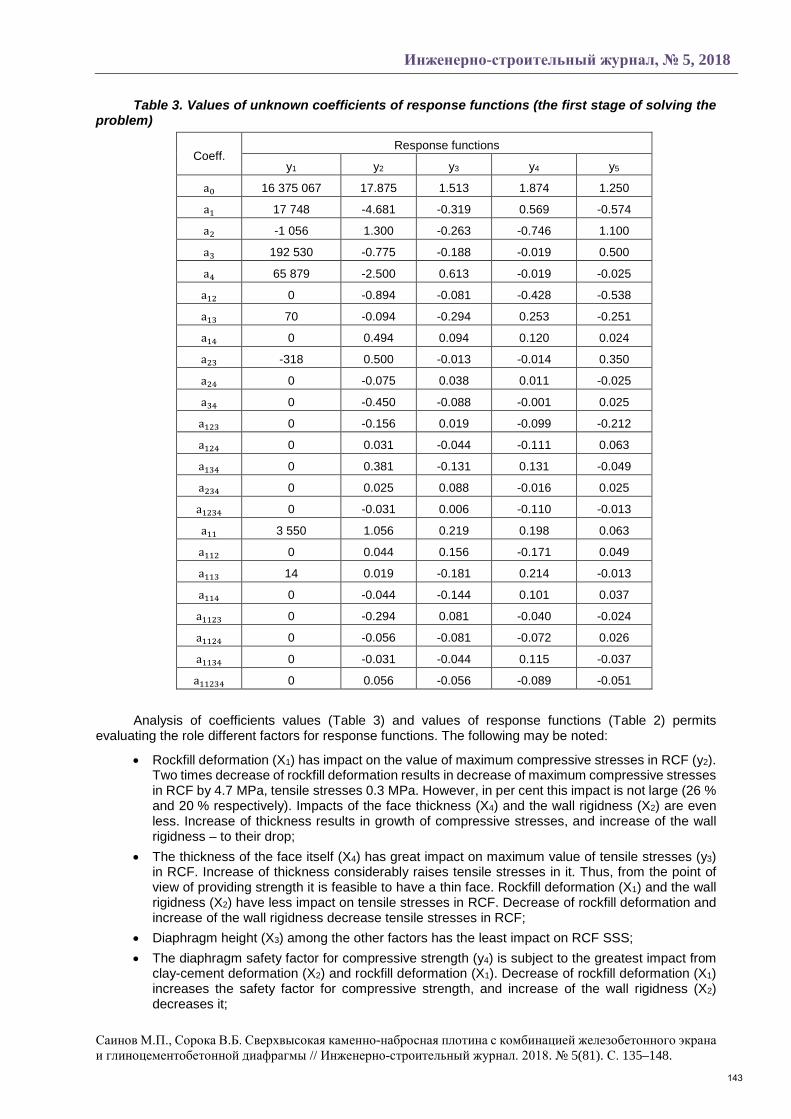
By the values of response functions the polynomial coefficients ai were determined for response functions. They were determined by solving the system of 24 linear algebraic equations:
�y1 = a0 + a1 ∗ X1+. … … … … … + a11234 ∗ X12 ∗ X2 ∗ X3 ∗ X4
… … … … … … … … … … … … … … … … … … … … … … … … … … … … …yn = a0 + a1 ∗ X1,n+. … … … … … + a11234 ∗ X1,n
2 ∗ X2,n ∗ X3,n ∗ X4,n
For each of the response function we obtained the system of 24 equations, where values yn and Xi,n are known and values of ai are unknown. By solving the system equations we obtained the values of coefficients ai (Table 3).
142
Инженерно-строительный журнал, № 5, 2018
Саинов М.П., Сорока В.Б. Сверхвысокая каменно-набросная плотина с комбинацией железобетонного экрана и глиноцементобетонной диафрагмы // Инженерно-строительный журнал. 2018. № 5(81). С. 135–148.
Table 3. Values of unknown coefficients of response functions (the first stage of solving the problem)
Coeff. Response functions
y1 y2 y3 y4 y5
a0 16 375 067 17.875 1.513 1.874 1.250
a1 17 748 -4.681 -0.319 0.569 -0.574
a2 -1 056 1.300 -0.263 -0.746 1.100
a3 192 530 -0.775 -0.188 -0.019 0.500
a4 65 879 -2.500 0.613 -0.019 -0.025
a12 0 -0.894 -0.081 -0.428 -0.538
a13 70 -0.094 -0.294 0.253 -0.251
a14 0 0.494 0.094 0.120 0.024
a23 -318 0.500 -0.013 -0.014 0.350
a24 0 -0.075 0.038 0.011 -0.025
a34 0 -0.450 -0.088 -0.001 0.025
a123 0 -0.156 0.019 -0.099 -0.212
a124 0 0.031 -0.044 -0.111 0.063
a134 0 0.381 -0.131 0.131 -0.049
a234 0 0.025 0.088 -0.016 0.025
a1234 0 -0.031 0.006 -0.110 -0.013
a11 3 550 1.056 0.219 0.198 0.063
a112 0 0.044 0.156 -0.171 0.049
a113 14 0.019 -0.181 0.214 -0.013
a114 0 -0.044 -0.144 0.101 0.037
a1123 0 -0.294 0.081 -0.040 -0.024
a1124 0 -0.056 -0.081 -0.072 0.026
a1134 0 -0.031 -0.044 0.115 -0.037
a11234 0 0.056 -0.056 -0.089 -0.051
Analysis of coefficients values (Table 3) and values of response functions (Table 2) permits evaluating the role different factors for response functions. The following may be noted:
• Rockfill deformation (X1) has impact on the value of maximum compressive stresses in RCF (y2). Two times decrease of rockfill deformation results in decrease of maximum compressive stresses in RCF by 4.7 MPa, tensile stresses 0.3 MPa. However, in per cent this impact is not large (26 % and 20 % respectively). Impacts of the face thickness (X4) and the wall rigidness (X2) are even less. Increase of thickness results in growth of compressive stresses, and increase of the wall rigidness – to their drop;
• The thickness of the face itself (X4) has great impact on maximum value of tensile stresses (y3) in RCF. Increase of thickness considerably raises tensile stresses in it. Thus, from the point of view of providing strength it is feasible to have a thin face. Rockfill deformation (X1) and the wall rigidness (X2) have less impact on tensile stresses in RCF. Decrease of rockfill deformation and increase of the wall rigidness decrease tensile stresses in RCF;
• Diaphragm height (X3) among the other factors has the least impact on RCF SSS; • The diaphragm safety factor for compressive strength (y4) is subject to the greatest impact from
clay-cement deformation (X2) and rockfill deformation (X1). Decrease of rockfill deformation (X1) increases the safety factor for compressive strength, and increase of the wall rigidness (X2) decreases it;
143
Magazine of Civil Engineering, No. 5, 2018
Sainov, M.P., Soroka, V.B. Ultra-high rockfill dam with combination of the reinforced concrete face and clay-cement diaphragm. Magazine of Civil Engineering. 2018. 81(5). Pp. 135–148. doi: 10.18720/MCE.81.14.
• Maximum values of tensile stresses in the diaphragm (y5) are mostly subject to the impact of clay-cement deformation (X2). Its impact is more than the impact of rockfill deformation (X1) and the diaphragm height (X3);
• Use of quadratic dependences of response functions from factor X1 permitted reflecting their non-linear character especially by responses y2 and y3;
• The impact of several factors interaction should not be neglected. Mainly this refers to interaction of factors X1 with X2 and with X3.
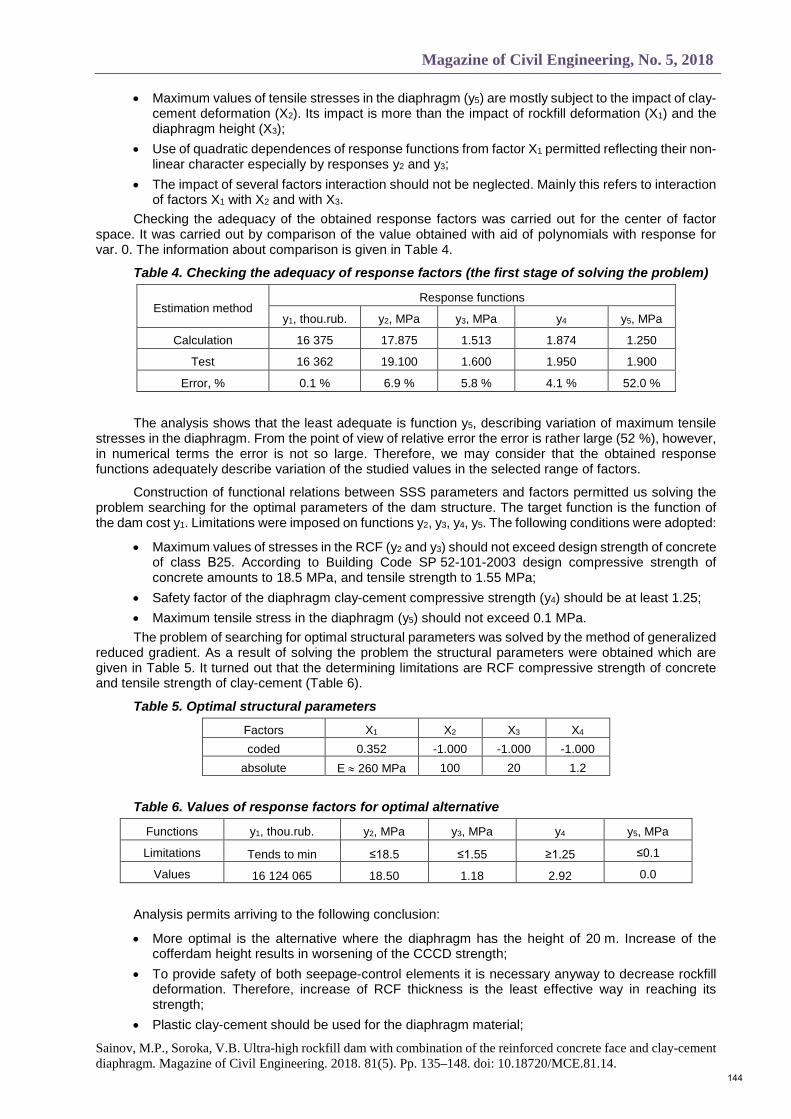
Checking the adequacy of the obtained response factors was carried out for the center of factor space. It was carried out by comparison of the value obtained with aid of polynomials with response for var. 0. The information about comparison is given in Table 4.
Table 4. Checking the adequacy of response factors (the first stage of solving the problem)
Estimation method Response functions
y1, thou.rub. y2, MPa y3, MPa y4 y5, MPa
Calculation 16 375 17.875 1.513 1.874 1.250
Test 16 362 19.100 1.600 1.950 1.900
Error, % 0.1 % 6.9 % 5.8 % 4.1 % 52.0 %
The analysis shows that the least adequate is function y5, describing variation of maximum tensile stresses in the diaphragm. From the point of view of relative error the error is rather large (52 %), however, in numerical terms the error is not so large. Therefore, we may consider that the obtained response functions adequately describe variation of the studied values in the selected range of factors.
Construction of functional relations between SSS parameters and factors permitted us solving the problem searching for the optimal parameters of the dam structure. The target function is the function of the dam cost y1. Limitations were imposed on functions y2, y3, y4, y5. The following conditions were adopted:
• Maximum values of stresses in the RCF (y2 and y3) should not exceed design strength of concrete of class В25. According to Building Code SP 52-101-2003 design compressive strength of concrete amounts to 18.5 MPa, and tensile strength to 1.55 MPa;
• Safety factor of the diaphragm clay-cement compressive strength (y4) should be at least 1.25; • Maximum tensile stress in the diaphragm (y5) should not exceed 0.1 MPa. The problem of searching for optimal structural parameters was solved by the method of generalized
reduced gradient. As a result of solving the problem the structural parameters were obtained which are given in Table 5. It turned out that the determining limitations are RCF compressive strength of concrete and tensile strength of clay-cement (Table 6).
Table 5. Optimal structural parameters
Factors X1 X2 X3 X4 coded 0.352 -1.000 -1.000 -1.000
absolute E ≈ 260 MPa 100 20 1.2
Table 6. Values of response factors for optimal alternative
Functions y1, thou.rub. y2, MPa y3, MPa y4 y5, MPa
Limitations Tends to min ≤18.5 ≤1.55 ≥1.25 ≤0.1
Values 16 124 065 18.50 1.18 2.92 0.0
Analysis permits arriving to the following conclusion:
• More optimal is the alternative where the diaphragm has the height of 20 m. Increase of the cofferdam height results in worsening of the CCCD strength;
• To provide safety of both seepage-control elements it is necessary anyway to decrease rockfill deformation. Therefore, increase of RCF thickness is the least effective way in reaching its strength;
• Plastic clay-cement should be used for the diaphragm material;
144
Инженерно-строительный журнал, № 5, 2018
Саинов М.П., Сорока В.Б. Сверхвысокая каменно-набросная плотина с комбинацией железобетонного экрана и глиноцементобетонной диафрагмы // Инженерно-строительный журнал. 2018. № 5(81). С. 135–148.
• The fact that value X1 was not reached to be maximum possible is explained by a complicated character of rockfill deformation impact on the structure working ability. Selection of rockfill deformability (X1) conditions selection of clay-cement deformability (X2). If clay-cement deformability turns out to be less than that of rockfill, this may affect the RCF SSS.
Solving the problem on optimization showed that two of four factors do not need to be changed – the optimal solution corresponds to the case when the values of these factors are on the boundary of the factor space. These are the factors characterizing the dam geometry: X3 (diaphragm height) and X4 (RCF thickness). The most feasible alternatives are those where the diaphragm height and RCF thickness are minimum (20 m and 1.2 m respectively). These factors were excluded from further consideration.
At the second stage at searching for the optimal structure 2 factors varied: X1 (dam body rockfill deformation) and X2 (clay-cement diaphragm deformation). The dam structural design was considered where the diaphragm height is 20 m the RCF thickness is minimal.
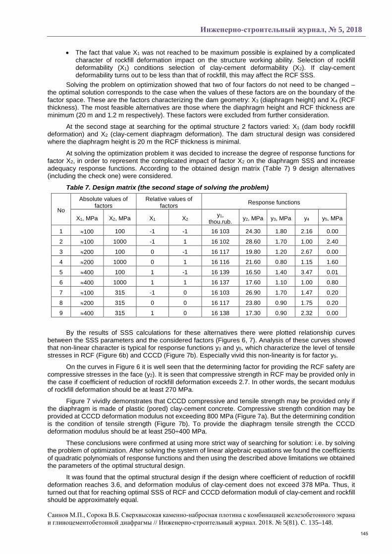
At solving the optimization problem it was decided to increase the degree of response functions for factor X2, in order to represent the complicated impact of factor X2 on the diaphragm SSS and increase adequacy response functions. According to the obtained design matrix (Table 7) 9 design alternatives (including the check one) were considered.
Table 7. Design matrix (the second stage of solving the problem)
No
Absolute values of factors
Relative values of factors Response functions
X1, MPa X2, MPa X1 X2 y1, thou.rub. y2, MPa y3, MPa y4 y5, MPa
1 ≈100 100 -1 -1 16 103 24.30 1.80 2.16 0.00
2 ≈100 1000 -1 1 16 102 28.60 1.70 1.00 2.40
3 ≈200 100 0 -1 16 117 19.80 1.20 2.67 0.00
4 ≈200 1000 0 1 16 116 21.60 0.80 1.15 1.60
5 ≈400 100 1 -1 16 139 16.50 1.40 3.47 0.01
6 ≈400 1000 1 1 16 137 17.60 1.10 1.00 0.80
7 ≈100 315 -1 0 16 103 26.90 1.70 1.47 0.20
8 ≈200 315 0 0 16 117 23.80 0.90 1.75 0.20
9 ≈400 315 1 0 16 138 17.30 0.90 2.32 0.00
By the results of SSS calculations for these alternatives there were plotted relationship curves between the SSS parameters and the considered factors (Figures 6, 7). Analysis of these curves showed that non-linear character is typical for response functions y3 and y5, which characterize the level of tensile stresses in RCF (Figure 6b) and CCCD (Figure 7b). Especially vivid this non-linearity is for factor y5.
On the curves in Figure 6 it is well seen that the determining factor for providing the RCF safety are compressive stresses in the face (y2). It is seen that compressive strength in RCF may be provided only in the case if coefficient of reduction of rockfill deformation exceeds 2.7. In other words, the secant modulus of rockfill deformation should be at least 270 MPa.
Figure 7 vividly demonstrates that CCCD compressive and tensile strength may be provided only if the diaphragm is made of plastic (pored) clay-cement concrete. Compressive strength condition may be provided at CCCD deformation modulus not exceeding 800 MPa (Figure 7a). But the determining condition is the condition of tensile strength (Figure 7b). To provide the diaphragm tensile strength the CCCD deformation modulus should be at least 250÷400 MPa.
These conclusions were confirmed at using more strict way of searching for solution: i.e. by solving the problem of optimization. After solving the system of linear algebraic equations we found the coefficients of quadratic polynomials of response functions and then using the described above limitations we obtained the parameters of the optimal structural design.
It was found that the optimal structural design if the design where coefficient of reduction of rockfill deformation reaches 3.6, and deformation modulus of clay-cement does not exceed 378 MPa. Thus, it turned out that for reaching optimal SSS of RCF and CCCD deformation moduli of clay-cement and rockfill should be approximately equal.
145

Magazine of Civil Engineering, No. 5, 2018
Sainov, M.P., Soroka, V.B. Ultra-high rockfill dam with combination of the reinforced concrete face and clay-cement diaphragm. Magazine of Civil Engineering. 2018. 81(5). Pp. 135–148. doi: 10.18720/MCE.81.14.
a) Coefficient of reduction of rockfill
deformation
b) Coefficient of reduction of rockfill deformation
Figure 6. Variation of RCF parameters of SSS depending on rockfill deformation and the diaphragm deformation modulus of clay-cement (Ed)
a – maximum compressive stresses; b – maximum tensile stresses. The dotted line shows the limitation established for the factor
a) b)
Figure 7. Variation of the diaphragm SSS parameters depending on rockfill deformation and deformation modulus of the diaphragm clay-cement (Ed)
a – safety factor for compression strength; b – maximum tensile stresses. The dotted line shows the limitation established for the factor
Thus solving the problem of optimization permitted revealing main principals in selection of structural design parameters of a rockfill dam with combined seepage-control element, revealing main trends of its optimization. However, the final solution of the problem has not yet reached and there are several reasons for it. First of all, the values of some variable factors in the optimal structural design turned to be at the boundary of the factor space. This means that the structure may be optimized even more extensively. Secondly, there are other ways of enhancing the structure efficiency. Namely, decrease of tensile stresses in the wall may be reached by changing the layout of the diaphragm contact with rock foundation. By the results of studies arrangement of clay-cement «pad» makes the diaphragm free from bending and tensile deformations. This promises the way of further refinement of the dam structural design.
4. Conclusions 1. The rockfill dam with a combined seepage-control element (consisting of a reinforced concrete
face and a clay-cement diaphragm) may be a rather safe type of the dam even in conditions of a high head (more than 200 m). For this purpose it is necessary to follow the principles, which were obtained as a result of this study.
2. The main principles of designing the dams of the considered type are as follows:
• Rockfill deformation modulus should be at least 250 MPa in order to provide strength of the reinforced concrete face and the clay-cement diaphragm;
146

Инженерно-строительный журнал, № 5, 2018
Саинов М.П., Сорока В.Б. Сверхвысокая каменно-набросная плотина с комбинацией железобетонного экрана и глиноцементобетонной диафрагмы // Инженерно-строительный журнал. 2018. № 5(81). С. 135–148.
• In spite of the fact that increase of the reinforced concrete face thickness seems to be a simple way of enhancing its strength, there is no need of making it too massive. This is connected with the fact that for providing safety of all structural elements rockfill should be very well compacted. The RCF thickness should be taken equal 0.5 % of the dam height;
• It is desirable that deformation modulus of clay-cement and rockfill were equal. Here the rule may be used, according to which clay-cement deformation modulus should have 2 times difference from rockfill deformation modulus.
3. There are ways of further enhancing safety of a rockfill dam with a combined seepage-control element. Namely, for reducing the danger of appearance in the diaphragm tensile stresses from bending deformations it is feasible to conjugate the diaphragm with rock foundation with the aid of a clay-cement “pad”.
References 1. Zhongming, J., Qing J. Shuibuya: The world’s highest
concrete faced rockfill dam. The International Journal on Hydropower & Dams. 2000. Vol. 7. No. 4. Pp. 94–97.
2. Freitas, M.S.Jr. Concepts on CFRDs Leakage Control – Cases and Current Experiences. ISSMGE Bulletin. 2009. Vol. 3. No. 4. Pp. 11–18.
3. Song, W., Sun, Y., Li, L., Wang, Y. Reason analysis and treatment for the 1st phase slab cracking of Shuibuya CFRD. Journal of Hydroelectric Engineering. 2008. No. 3(27). Pp. 33–37.
4. Markes Filo P., Pinto N. de S. Kharakteristiki kamenno–nabrosnykh plotin s betonnym ekranom, poluchennyye opytnym putem [Features rockfill dam with a concrete screen, obtained by experience]. Mezhdunarodnyy daydzhest po gidroenergetike i plotinam. 2007. Pp. 69–74.
5. Silva da, A.F., Assis de, A.P., Neto, M.P.C. Three–Dimensional Analyses of Concrete Face Rockfill Dams: Barra Grande Case Study. Electronic Journal of Geotechnical Engineering. 2015. Vol. 20. Bund 14. Pp. 6407–6426.
6. Barra Grande Hydropower Plant. Design, Construction and Perfomance. Main Brazilian Dams III. [Online]. System requirements: AdobeAcrobatReader. URL: http://www.cbdb.org.br/documentos/mbdiii/Barra%20grande.pdf.
7. Johannesson, P., Tohlang, S.L. Lessons learned from Mohale. The International Water Power & Dam Construction. August 2007. Vol. 59. No. 8. Pp. 16–18+20–22+24–25.
8. Sobrinho, J.A., Xavier, L.V., Albertoni, S.C., Pereira, R.F. Performance and Concrete Face Repair at Campos Novos. The International Journal on Hydropower & Dams. 2007. No. 14(2). Pp. 39–42.
9. Xavier, L.V., Albertoni, S.C., Pereira R.F., Antunes J. Campos Novos dam during second impounding. The International Journal on Hydropower & Dams. 2008. No. 15. Pp. 53–58.
10. Li, N.-H., Sun, D.-W., Li, D.-H., Deng, Y.-G., Yang, J. Deformation behavior of 300 m high–concrete face rockfill dams. Yantu Gongcheng Xuebao / Chinese Journal of Geotechnical Engineering. 2009. No. 31(2). Pp. 155–160.
11. Luo, D., Luo, L. Study and engineering practice on cracks control measures for concrete face slab of high CFRD. Advanced Materials Research. 2012. Vol. 455–456. Pp. 1606–1611.
12. Li, N.-H. Performance of high concrete face rockfill dams in China and its inspiration. Yantu Gongcheng Xuebao / Chinese Journal of Geotechnical Engineering. 2011. No. 33(2). Pp. 165–173
13. Sun, D., Zhang, G., Wang, K., Yao, H. 3D finite element analysis on a 270m rockfill dam based on Duncan–Chang E–B model. Advanced Materials Research. 2011. Pp. 287–290, 1213–1216.
Литература 1. Zhongming J., Qing J. Shuibuya: The world’s highest
concrete faced rockfill dam // The International Journal on Hydropower & Dams. 2000. Vol. 7. № 4. Pp. 94–97.
2. Freitas M.S.Jr. Concepts on CFRDs Leakage Control – Cases and Current Experiences // ISSMGE Bulletin. 2009. Vol. 3. № 4. Pp. 11–18.
3. Song W., Sun Y., Li L., Wang Y. Reason analysis and treatment for the 1st phase slab cracking of Shuibuya CFRD // Journal of Hydroelectric Engineering. 2008. № 3(27). Pp. 33–37.
4. Маркес Фильо П., Пинто Н. де С. Характеристики каменно–набросных плотин с бетонным экраном, полученные опытным путем // Международный дайджест по гидроэнергетике и плотинам. 2007. С. 69–74.
5. Silva da A.F., Assis de A.P., Neto M.P.C. Three–Dimensional Analyses of Concrete Face Rockfill Dams: Barra Grande Case Study // Electronic Journal of Geotechnical Engineering. 2015. Vol. 20. Bund 14. Pp. 6407–6426.
6. Barra Grande Hydropower Plant. Design, Construction and Perfomance. Main Brazilian Dams III. [Электронный ресурс]. Сист.требования: AdobeAcrobatReader. URL: http://www.cbdb.org.br/documentos/ mbdiii/Barra%20grande.pdf.
7. Johannesson P., Tohlang S.L. Lessons learned from Mohale // The International Water Power & Dam Construction. August 2007. Vol. 59. № 8. Pp. 16–18+20–22+24–25.
8. Sobrinho J.A., Xavier L.V., Albertoni S.C., Pereira R.F. Performance and Concrete Face Repair at Campos Novos // The International Journal on Hydropower & Dams. 2007. № 14(2). Pp. 39–42.
9. Xavier L.V., Albertoni S.C., Pereira R.F., Antunes J. Campos Novos dam during second impounding // The International Journal on Hydropower & Dams. 2008. № 15. Pp. 53–58.
10. Li N.-H., Sun D.-W., Li D.-H., Deng Y.-G., Yang J. Deformation behavior of 300 m high–concrete face rockfill dams // Yantu Gongcheng Xuebao / Chinese Journal of Geotechnical Engineering. 2009. № 31(2). Pp. 155–160.
11. Luo D., Luo L. Study and engineering practice on cracks control measures for concrete face slab of high CFRD. Advanced Materials Research. 2012. Vol. 455–456, Pp. 1606–1611.
12. Li N.-H. Performance of high concrete face rockfill dams in China and its inspiration // Yantu Gongcheng Xuebao / Chinese Journal of Geotechnical Engineering. 2011. № 33(2). Pp. 165–173.
13. Sun D., Zhang G., Wang K., Yao H. 3D finite element analysis on a 270m rockfill dam based on Duncan–Chang E–B model // Advanced Materials Research. 2011. Pp. 287–290, 1213–1216.
147
Magazine of Civil Engineering, No. 5, 2018
Sainov, M.P., Soroka, V.B. Ultra-high rockfill dam with combination of the reinforced concrete face and clay-cement diaphragm. Magazine of Civil Engineering. 2018. 81(5). Pp. 135–148. doi: 10.18720/MCE.81.14.
14. Zhang, Z. Development of super–high concrete face rockfill dams in China. 14th Asian Regional Conference on Soil Mechanics and Geotechnical Engineering. 2011.
15. Zhang, Z.-L. Design and technical innovation of rockfill dam projects. Yantu Gongcheng Xuebao / Chinese Journal of Geotechnical Engineering. 2007. No. 29(8). Pp. 1184–1193.
16. Sainov, M.P. Impact of dam site configuration on 3D stress-strain state of concrete faced rockfill dam. Magazine of Civil Engineering. 2016. No. 3. Pp. 16–39. doi: 10.5862/MCE.63.2 (rus)
17. Sainov, M.P. Analysis of normal operation of a rockfill dam with combination of seepage-control elements: reinforced concrete face and a clay-cement-concrete wall. Magazine of Civil Engineering. 2016. No. 4. Pp. 3–9. doi: 10.5862/MCE.64.1
18. Sainov, M.P., Soroka, V.B. Rabotosposobnost sverkhvysokoy kamenno–nabrosnoy plotiny s kombinatsiyey negruntovykh protivofiltratsionnykh ustroystv [Workability of a ultra–high rockfill dam in combination with non–soil seepage–control facilities]. Privolzhskiy nauchnyy zhurnal. 2017. No. 3(43). Pp. 70–76.
19. Tang, J.-S., Ding, B.-M. Design of concrete face rockfill dam of the expansion project of Hengshan Reservoir. Water Power. 2002. No. 28(7). Pp. 35–37. (chinese)
20. Rasskazov, L.N., Dzhkha, Dzh. Deformiruyemost i prochnost grunta pri raschete vysokikh gruntovykh plotin [Deformability and Strength of Soils in High Soil Dam Calculation]. Gidrotekhnicheskoye stroitelstvo. 1987. No. 7. Pp. 31–36.
21. Malyshev, L.I., Shishov, I.N., Kudrin, K.P., Bardyugov, V.G. Tekhnicheskiye resheniya i rezultaty rabot po sooruzheniyu protivofiltratsionnoy steny v grunte v yadre i osnovanii Kureyskoy GES [Technical Solutions and Working Results in the Process of Building Filtration–proof Wall in the Soil of the Core and Foundation of Kureyskaya Water Power Plant]. Gidrotekhnicheskoye stroitelstvo, 2001. No. 3. Pp. 31–36.
22. Mirghasemi, A.A., Pakzad, M., Shadravan, B. The world’s largest cutoff wall at Karkheh dam. The International Journal on Hydropower & Dams. 2005. No. 2. Pp. 2–6.
23. Sainov, M.P. Vychislitelnaya programma po raschetu napryazhenno–deformirovannogo sostoyaniya gruntovykh plotin: opyt sozdaniya, metodiki i algoritmy [Computer program for the calculation of the stress–strain state of soil dams: the experience of creation, techniques and algorithms]. International Journal for Computational Civil and Structural Engineering. 2013. No. 9(4). Pp. 208–225.
24. Kahl, T.W., Kauschinger, J.L., Perry, E.B. Plastic concrete cutoff walls for Earth Dams. Departament of the Army US Army Corps of Engineers. 1991. 119 p.
25. Rasskazov, L.N., Radzinskiy, A.V., Sainov, M.P. Strength and Deformability of Clay–cement in Complex Stress State. Technology and Engineering. 2015. Vol. 48(5). Pp. 29–33.
14. Zhang Z. Development of super–high concrete face rockfill dams in China // 14th Asian Regional Conference on Soil Mechanics and Geotechnical Engineering. 2011.
15. Zhang Z.-L. Design and technical in№vation of rockfill dam projects // Yantu Gongcheng Xuebao / Chinese Journal of Geotechnical Engineering. 2007. № 29(8). Pp. 1184–1193.
16. Саинов М.П. Влияние формы створа на напряжённое состояние железобетонного экрана каменно-насыпной плотины // Инженерно-строительный журнал. 2016. № 3(63). С. 16–39.
17. Саинов М.П. Анализ работоспособности каменной плотины с комбинацией противофильтрационных элементов – железобетонного экрана и глиноцементобетонной стены // Инженерно-строительный журнал. 2016. № 4(64). С. 3–9.
18. Саинов М.П., Сорока В.Б. Работоспособность сверхвысокой каменно– набросной плотины с комбинацией негрунтовых противофильтрационных устройств // Приволжский научный журнал. 2017. № 3(43). С. 70–76.
19. Tang J.-S., Ding B.-M. Design of concrete face rockfill dam of the expansion project of Hengshan Reservoir // Water Power. 2002. № 28(7). Pp. 35–37.
20. Рассказов Л.Н., Джха Дж. Деформируемость и прочность грунта при расчете высоких грунтовых плотин // Гидротехническое строительство. 1987. № 7. С. 31–36.
21. Малышев Л.И., Шишов И.Н., Кудрин К.П., Бардюгов В.Г. Технические решения и результаты работ по сооружению противофильтрационной стены в грунте в ядре и основании Курейской ГЭС // Гидротехническое строительство. 2001. № 3. С. 31–36.
22. Mirghasemi A.A., Pakzad M., Shadravan B. The world’s largest cutoff wall at Karkheh dam // The International Journal on Hydropower & Dams. 2005. № 2. Pp. 2–6.
23. Саинов М.П. Вычислительная программа по расчёту напряжённо–деформированного состояния грунтовых плотин: опыт создания, методики и алгоритмы // International Journal for Computational Civil and Structural Engineering. 2013. № 9(4). С. 208–225.
24. Kahl T.W., Kauschinger J.L., Perry E.B. Plastic concrete cutoff walls for Earth Dams. Departament of the Army US Army Corps of Engineers. 1991. 119 p.
25. Рассказов Л.Н., Радзинский А.В., Саинов М.П. Прочность и деформируемость глиноцементобетона в сложном напряженном состоянии // Гидротехническое строительство. 2014. №8. С. 29–33.
Mikhail Sainov*, +7(926)607-89-31; [email protected] Vladislav Soroka, +7(929)503-49-72; [email protected]
Михаил Петрович Саинов*, +7(926)607-89-31; эл. почта: [email protected] Владислав Борисович Сорока, +7(929)503-49-72; эл. почта: [email protected]
© Sainov M.P.,Soroka V.B.,2018
148