ultra high quality factor and wide dynamic range inertial ...€¦ · inertial mems for...
TRANSCRIPT
ULTRA HIGH QUALITY FACTOR AND WIDE DYNAMIC RANGE
INERTIAL MEMS FOR NORTH-FINDING AND TRACKING APPLICATIONS
Alexander A. Trusov
MicroSystems Laboratory, University of California, Irvine, USA
[email protected], http://www.AlexanderTrusov.com, http://mems.eng.uci.edu
ABSTRACT We report high-Q and wide dynamic range MEMS
gyroscopes and accelerometers for development of a
very compact IMU capable of North finding and
tracking over dynamic environment. The vacuum
packaged SOI rate sensors utilize symmetric Quadru-
ple Mass Gyroscope (QMG) architecture with meas-
ured quality factors of 1.2 million and proven sub–
°/hr Allan deviation of bias. The true North detection
was accomplished in conventional amplitude modu-
lated (AM) rate measuring mode and showed 0.003
radian measurement uncertainty. The North (azimuth)
tracking over dynamic environment necessitates a wide dynamic range, for which the same QMG trans-
ducer is switched to a frequency modulated (FM) mo-
dality. The test results for FM operation experimen-
tally demonstrated a wide linear input rate range of
18,000 °/s and inherent self-calibration against tem-
perature changes. Vertical alignment of the IMU and
acceleration sensing is enabled using resonant accel-
erometers with 5 μg performance. The accelerometer
is self-calibrated against temperature variations, ena-
bled by differential frequency measurements. We be-
lieve the developed low dissipation inertial MEMS with interchangeable AM/FM modalities may enable
wide dynamic range IMUs for North-finding and iner-
tial guidance applications previously limited to sys-
tems based on optical and quartz inertial sensors.
I. INTRODUCTION
North-finding with 0.001 radian (1 mrad) preci-
sion and tracking of azimuth in a wide dynamic
range is required for targeting, dead reckoning, and
inertial guidance applications [1]. North identifica-
tion is traditionally accomplished using the magnetic
f i e ld of the Earth. However, there are a number of
spatial and temporal distortions in the magnetic field,
which limit the accuracy of this method. Practical
limitations of alternatives such as geodetic, celestial,
and GPS-based methods make high performance gy-roscopes desirable for true North seeking, or
gyrocompassing. Although conventional fiber optic,
ring laser, and macro-scale quartz hemispherical res-
onator gyroscopes can be used for precision
gyrocompassing, they are not perfectly suited for
man-portable and small platform applications.
MEMS, in contrast, have a number of b e n e f i t s
they are lightweight, low-power, batch fabricated, and
are have the potential to enable very small and
low cost IMU and INS technologies.
Gyrocompassing typically requires better than
0.05 °/hr total bias error over temperature variations
for repeatable measurements of the Earth’s rate and
0.1 mg total bias error for vertical alignment. Sev-eral groups have reported silicon MEMS gyroscopes
with sub–°/hr Allan deviation of bias [2-7]. However,
single digit mrad North-finding and tracking over dy-
namic environment is still view as unattainable by
MEMS technology [8]. We propose to tackle this
issue using the recently developed Quadruple Mass
Gyroscope (QMG) [9] and a new resonant accel-
erometer, with the resolution enhanced by high Q-
factors and wide dynamic range provided by frequen-
cy modulated (FM) operation, which is also robust to
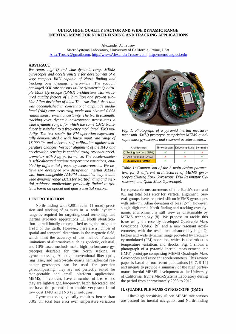
temperature variations and shocks. Fig. 1 shows a photograph of a pyramid inertial measurement unit
(IMU) prototype comprising MEMS Quadruple Mass
Gyroscopes and resonant accelerometers. This review
paper is based on our recent publications [6, 7, 9-14]
and intends to provide a summary of the high perfor-
mance inertial MEMS development at the University
of California, Irvine MicroSystems Laboratory during
the period from approximately 2008 to 2012.
II. QUADRUPLE MASS GYROSCOPE (QMG)
Ultra-high sensitivity silicon MEMS rate sensors
are desired for inertial navigation and North-finding
Fig. 1: Photograph of a pyramid inertial measure-ment unit (IMU) prototype comprising MEMS quad-
ruple mass gyroscopes and resonant accelerometers.
Table 1: Comparison of the 3 main design parame-
ters for 3 different architectures of MEMS gyro-
scopes (Tuning Fork Gyroscope, Disk Resonator Gy-
roscope, and Quad Mass Gyroscope).
applications. An optimal architecture of a high resolu-
tion vibratory rate gyroscope comprises a symmetric
mechanical structure with combination of very high
Q-factors and decay time constant, high Coriolis cou-
pling (angle gain), drive- and sense-mode degeneracy,
and frequency tuning capability [4]. Most of these
requirements can be satisfied by continuous structures
such as disks or rings operated in balanced wine-glass
modes. However, optimization of the performance parameters for such architectures is challenging due to
the inherent coupling of the natural frequency, Q-
factor, and drive-amplitude, Table 1. Frequency
trimming and tuning is also quite nontrivial for solid
structures as both mass and stiffness are collocated.
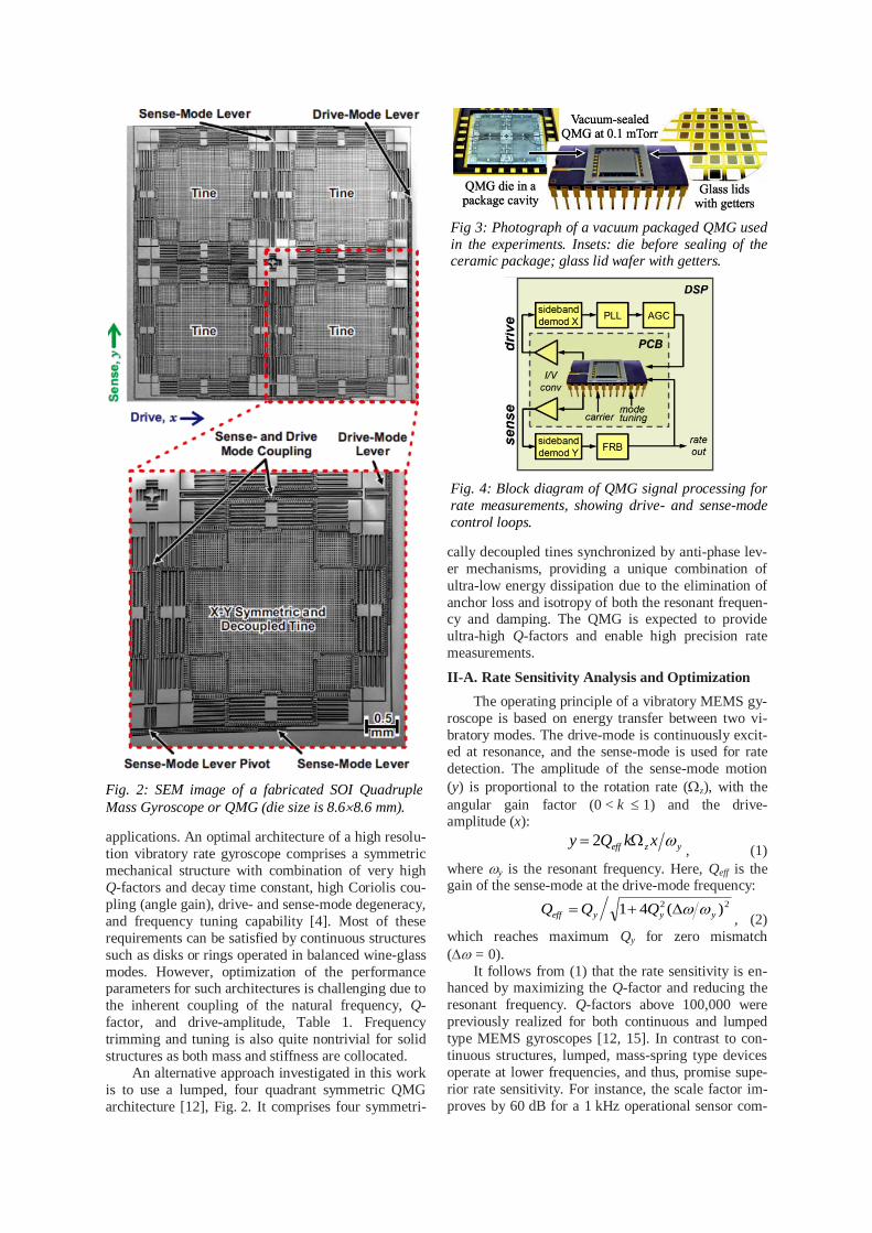
An alternative approach investigated in this work
is to use a lumped, four quadrant symmetric QMG
architecture [12], Fig. 2. It comprises four symmetri-
cally decoupled tines synchronized by anti-phase lev-
er mechanisms, providing a unique combination of
ultra-low energy dissipation due to the elimination of
anchor loss and isotropy of both the resonant frequen-cy and damping. The QMG is expected to provide
ultra-high Q-factors and enable high precision rate
measurements.
II-A. Rate Sensitivity Analysis and Optimization
The operating principle of a vibratory MEMS gy-
roscope is based on energy transfer between two vi-
bratory modes. The drive-mode is continuously excit-ed at resonance, and the sense-mode is used for rate
detection. The amplitude of the sense-mode motion
(y) is proportional to the rotation rate (z), with the
angular gain factor (0 < k 1) and the drive-amplitude (x):
yzeff xkQy 2, (1)
where y is the resonant frequency. Here, Qeff is the gain of the sense-mode at the drive-mode frequency:
22 )(41 yyyeff QQQ , (2)
which reaches maximum Qy for zero mismatch
( = 0).
It follows from (1) that the rate sensitivity is en-hanced by maximizing the Q-factor and reducing the
resonant frequency. Q-factors above 100,000 were
previously realized for both continuous and lumped
type MEMS gyroscopes [12, 15]. In contrast to con-
tinuous structures, lumped, mass-spring type devices
operate at lower frequencies, and thus, promise supe-
rior rate sensitivity. For instance, the scale factor im-
proves by 60 dB for a 1 kHz operational sensor com-
Fig. 2: SEM image of a fabricated SOI Quadruple
Mass Gyroscope or QMG (die size is 8.68.6 mm).
Fig 3: Photograph of a vacuum packaged QMG used
in the experiments. Insets: die before sealing of the ceramic package; glass lid wafer with getters.
Fig. 4: Block diagram of QMG signal processing for
rate measurements, showing drive- and sense-mode
control loops.
pared to a 1 MHz sensor. The trade-off between fre-
quency and sensitivity is a limited bandwidth, which
can be resolved by operating in a closed loop, or
force-rebalance (FRB) mode. In addition, mass-
spring, lumped architectures can provide high Coriolis
coupling (k ~ 1) and large amplitude of motion (up to 10 microns), which also increase the rate sensitivity.
Based on these considerations, we investigate a
lumped design approach for high precision applica-
tions.
II-B. Mechanical Design and Symmetry
Mode-matched operation over a wide temperature
range is desired for high-Q MEMS gyroscopes. Fre-
quency mismatch induced by fabrication imperfec-tions is typically compensated by electrostatic tuning,
which often requires high voltages and active con-
trols. In this work, we evaluate a design-level solution,
where structural symmetry of the lumped mechanical
element provides identical drive and sense tempera-
ture coefficients of frequency for increased robustness
to the temperature-induced drifts [13].
The recently introduced lumped Quadruple Mass
Gyroscope architecture, Fig. 2, comprises four identi-
cal tines, four linear coupling flexures, and a pair of
lever mechanisms for synchronization of the anti-phase drive- and sense-mode motion. Momentum and
torque balance in both x and y directions is expected
to provide ultra-low dissipation of energy through the
substrate, leading to a high resolution and equal ultra-
high Q-factors, Qx = Qy > 1 million. Symmetric lever
mechanisms and flexures ensure low operational fre-
quency (~ 2 kHz), as well as the common mode rejec-
tion of input accelerations, both required for high pre-
cision rate measurements.
II-C. MEMS Fabrication and Vacuum Packaging
Stand-alone prototypes of the QMG were fabri-
cated using an in-house 100 m SOI process with 5
m minimal gap size. The rate sensor was packaged using custom technology for robust vacuum sealing of
the high-Q gyroscopes [16], Fig. 3. First, the QMG
die was attached to a ceramic 24-pin package using
eutectic solder and wire bonded. The device was then
sealed at sub-mTorr vacuum, preceded by the getter
activation on a glass lid.
II-D. Interface and Control Electronics
All experiments were performed using a custom
PCB connected to a FPGA-based DSP unit. The vac-
uum packaged sensor was mounted on a PCB with
front-end electronics and installed on a 1291BR Ideal
Aerosmith rate table inside the thermal chamber.
Electrostatic capacitive actuation and detection were
employed along with the EAM technique for the para-
sitic feedthrough elimination. All control and signal
processing were realized using a LabView program-
mable, FPGA-based HF2 unit from Zurich Instru-ments.
Fig. 4 depicts drive- and sense-mode control
loops used for high precision angular rate measure-
ments. The PLL-based drive-loop sustained oscilla-
tion at resonance and provided reference for the side-
band demodulations. The AGC stabilized the ampli-
tude of drive-mode motion. Rotation was detected by
demodulating the sense-mode signal. Rate was pro-
portional to a feedback force used to null the Coriolis induced motion (FRB loop). The rate measurements
were performed at a 0.2 Hz separation between drive-
and sense-mode frequencies.
II-E. QMG Experimental Characterization
The damping and frequency symmetry of the
stand-alone QMG prototype with a 2 kHz operational
frequency was evaluated using ring-down tests in a
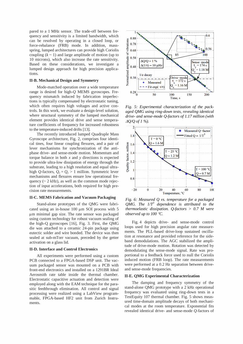
TestEquity 107 thermal chamber. Fig. 5 shows meas-ured time-domain amplitude decays of both mechani-
cal modes at the room temperature. Exponential fits
revealed identical drive- and sense-mode Q-factors of
Fig. 5: Experimental characterization of the pack-
aged QMG using ring-down tests, revealing identical
drive- and sense-mode Q-factors of 1.17 million (with
Q/Q of 1 %).
Fig. 6: Measured Q vs. temperature for a packaged
QMG. The 1/T3 dependence is attributed to the thermoelastic dissipation. Q-factors > 0.7 M were
observed up to 100 C.
1.17 million with Q/Q variation of 1 % before tuning or compensation, confirming the complete structural
symmetry. The measured Q value of 1.17 million is
within 90% of the 1.3 million thermoelastic limit es-
timated by finite element modeling for the QMG de-
sign. The ultra-high Q-factor translates into the fun-
damental mechanical-thermal resolution limit of
0.01 /hr/Hz for a mode-matched case. The temperature sensitivity of frequency and Q-
factor were characterized in the range from 5 C to
100 C. Isotropic Q-factors above 0.7 million were
experimentally observed up to 100 C for a packaged
QMG, Fig. 6. The fit to the Q(T) data revealed 1/T3 dependence, suggesting that the dominant energy loss
mechanism is thermoelastic dissipation [17]. Frequen-
cy symmetry of the QMG design was previously
evaluated in [12], and confirmed closely matched
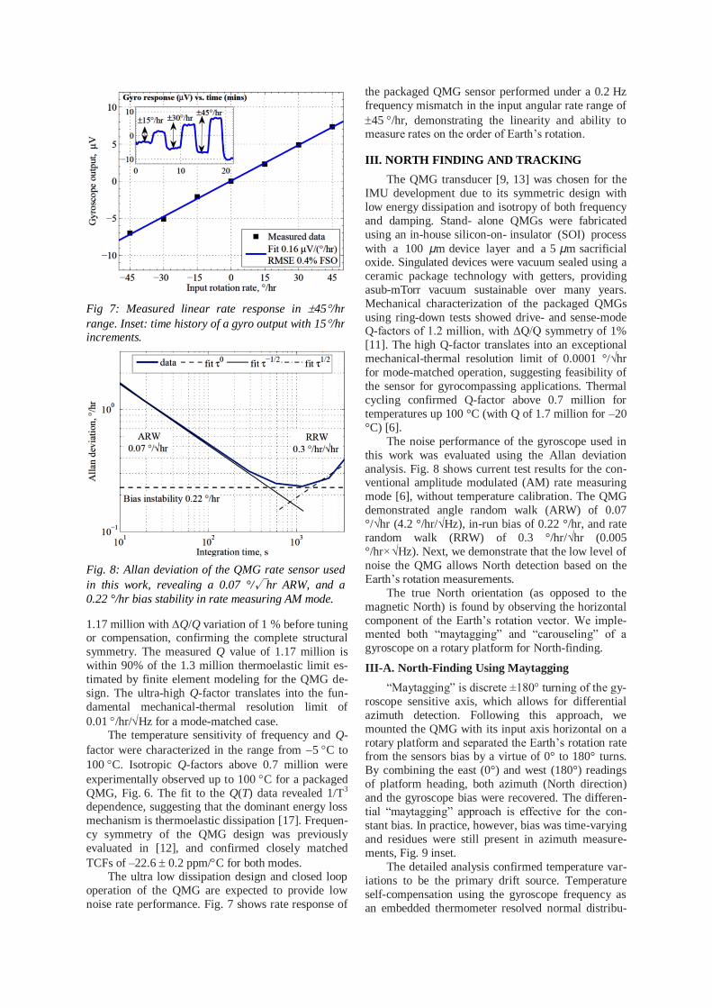
TCFs of –22.6 0.2 ppm/C for both modes. The ultra low dissipation design and closed loop
operation of the QMG are expected to provide low
noise rate performance. Fig. 7 shows rate response of
the packaged QMG sensor performed under a 0.2 Hz
frequency mismatch in the input angular rate range of
45 /hr, demonstrating the linearity and ability to measure rates on the order of Earth’s rotation.
III. NORTH FINDING AND TRACKING
The QMG transducer [9, 13] was chosen for the
IMU development due to its symmetric design with
low energy dissipation and isotropy of both frequency
and damping. Stand- alone QMGs were fabricated
using an in-house silicon-on- insulator (SOI) process
with a 100 μm device layer and a 5 μm sacrificial oxide. Singulated devices were vacuum sealed using a
ceramic package technology with getters, providing
asub-mTorr vacuum sustainable over many years.
Mechanical characterization of the packaged QMGs
using ring-down tests showed drive- and sense-mode Q-factors of 1.2 million, with ΔQ/Q symmetry of 1%
[11]. The high Q-factor translates into an exceptional
mechanical-thermal resolution limit of 0.0001 °/√hr
for mode-matched operation, suggesting feasibility of
the sensor for gyrocompassing applications. Thermal
cycling confirmed Q-factor above 0.7 million for
temperatures up 100 °C (with Q of 1.7 million for –20
°C) [6].
The noise performance of the gyroscope used in
this work was evaluated using the Allan deviation
analysis. Fig. 8 shows current test results for the con-ventional amplitude modulated (AM) rate measuring
mode [6], without temperature calibration. The QMG
demonstrated angle random walk (ARW) of 0.07
°/√hr (4.2 °/hr/√Hz), in-run bias of 0.22 °/hr, and rate
random walk (RRW) of 0.3 °/hr/√hr (0.005
°/hr×√Hz). Next, we demonstrate that the low level of
noise the QMG allows North detection based on the
Earth’s rotation measurements.
The true North orientation (as opposed to the
magnetic North) is found by observing the horizontal
component of the Earth’s rotation vector. We imple-mented both “maytagging” and “carouseling” of a
gyroscope on a rotary platform for North-finding.
III-A. North-Finding Using Maytagging
“Maytagging” is discrete ±180° turning of the gy-
roscope sensitive axis, which allows for differential
azimuth detection. Following this approach, we
mounted the QMG with its input axis horizontal on a
rotary platform and separated the Earth’s rotation rate from the sensors bias by a virtue of 0° to 180° turns.
By combining the east (0°) and west (180°) readings
of platform heading, both azimuth (North direction)
and the gyroscope bias were recovered. The differen-
tial “maytagging” approach is effective for the con-
stant bias. In practice, however, bias was time-varying
and residues were still present in azimuth measure-
ments, Fig. 9 inset.
The detailed analysis confirmed temperature var-
iations to be the primary drift source. Temperature
self-compensation using the gyroscope frequency as
an embedded thermometer resolved normal distribu-
Fig 7: Measured linear rate response in 45/hr
range. Inset: time history of a gyro output with 15/hr increments.
Fig. 8: Allan deviation of the QMG rate sensor used
in this work, revealing a 0.07 °/√hr ARW, and a
0.22 °/hr bias stability in rate measuring AM mode.
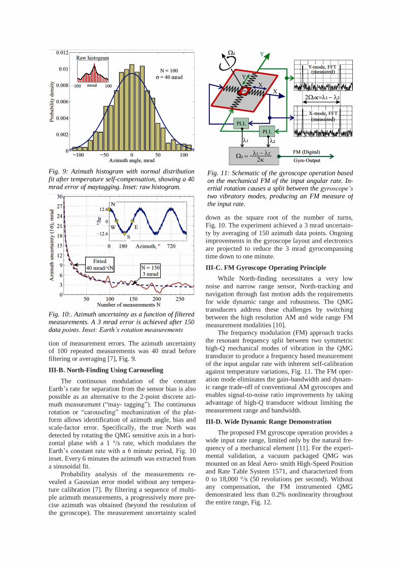
tion of measurement errors. The azimuth uncertainty of 100 repeated measurements was 40 mrad before
filtering or averaging [7], Fig. 9.
III-B. North-Finding Using Carouseling
The continuous modulation of the constant
Earth’s rate for separation from the sensor bias is also
possible as an alternative to the 2-point discrete azi-
muth measurement (“may- tagging”). The continuous
rotation or “carouseling” mechanization of the plat-form allows identification of azimuth angle, bias and
scale-factor error. Specifically, the true North was
detected by rotating the QMG sensitive axis in a hori-
zontal plane with a 1 °/s rate, which modulates the
Earth’s constant rate with a 6 minute period, Fig. 10
inset. Every 6 minutes the azimuth was extracted from
a sinusoidal fit.
Probability analysis of the measurements re-
vealed a Gaussian error model without any tempera-
ture calibration [7]. By filtering a sequence of multi-
ple azimuth measurements, a progressively more pre-cise azimuth was obtained (beyond the resolution of
the gyroscope). The measurement uncertainty scaled
down as the square root of the number of turns,
Fig. 10. The experiment achieved a 3 mrad uncertain-
ty by averaging of 150 azimuth data points. Ongoing
improvements in the gyroscope layout and electronics
are projected to reduce the 3 mrad gyrocompassing
time down to one minute.
III-C. FM Gyroscope Operating Principle
While North-finding necessitates a very low
noise and narrow range sensor, North-tracking and
navigation through fast motion adds the requirements
for wide dynamic range and robustness. The QMG
transducers address these challenges by switching
between the high resolution AM and wide range FM
measurement modalities [10]. The frequency modulation (FM) approach tracks
the resonant frequency split between two symmetric
high-Q mechanical modes of vibration in the QMG
transducer to produce a frequency based measurement
of the input angular rate with inherent self-calibration
against temperature variations, Fig. 11. The FM oper-
ation mode eliminates the gain-bandwidth and dynam-
ic range trade-off of conventional AM gyroscopes and
enables signal-to-noise ratio improvements by taking
advantage of high-Q transducer without limiting the
measurement range and bandwidth.
III-D. Wide Dynamic Range Demonstration
The proposed FM gyroscope operation provides a
wide input rate range, limited only by the natural fre-
quency of a mechanical element [11]. For the experi-
mental validation, a vacuum packaged QMG was
mounted on an Ideal Aero- smith High-Speed Position
and Rate Table System 1571, and characterized from
0 to 18,000 °/s (50 revolutions per second). Without any compensation, the FM instrumented QMG
demonstrated less than 0.2% nonlinearity throughout
the entire range, Fig. 12.
Fig. 11: Schematic of the gyroscope operation based
on the mechanical FM of the input angular rate. In-ertial rotation causes a split between the gyroscope’s
two vibratory modes, producing an FM measure of
the input rate.
Fig. 9: Azimuth histogram with normal distribution
fit after temperature self-compensation, showing a 40
mrad error of maytagging. Inset: raw histogram.
Fig. 10:. Azimuth uncertainty as a function of filtered
measurements. A 3 mrad error is achieved after 150
data points. Inset: Earth’s rotation measurements

Theoretical analysis of the proposed FM rate sen-
sor also suggests immunity against the temperature-
induced drifts by virtue of the differential frequency detection, i.e. by measuring the frequency split [10].
To experimentally investigate this concept, a vacuum
packaged QMG sensor operated in FM mode was
characterized on a temperature controlled Ideal Aer-
osmith 1291BR rate table. Without any active temper-
ature compensation, experimental characterization of
the FM instrumented QMG revealed less than 0.2%
scale-factor change from 25 °C to 70 °C, Fig. 13. De-
spite a 30% reduction of the Q-factor and a 5 Hz
change of the nominal frequency, the scale-factor
sensitivity was less than 50 ppm/°C (limited by the experimental setup noise), demonstrating temperature
robustness of the differential FM measurements.
The interchangeable AM/FM operation of the
QMG sensor is expected to provide wide dynamic
range for North-finding and North-tracking applica-
tions. The measured 0.22 °/hr bias instability of the
AM mode combined with the measured ±18,000 °/s
linear range of the FM mode enables the dynamic
range of at least 170 dB. This makes a single high-Q
MEMS transducer fitted for demanding high precision
and wide input range applications.
IV. SILICON ACCELEROMETER WITH
DIFFERENTIAL FREQUENCY MODULATION
While silicon MEMS accelerometers have proven
themselves as commercially successful devices, sig-
nificant challenges remain in bringing them to high
performance, mission critical applications. Conven-
tional micromachined pendulous accelerometers oper-
ate as analogue Amplitude Modulated (AM) systems,
with an inherent gain-bandwidth tradeoff and dynamic
range limited by the stability of capacitive pickoff
electronics. These analogue devices typically show
poor long term and environmental stability. Packaging
requirements for the highly damped pendulous accel-
erometers contradict the vacuum sealing requirements of high performance MEMS gyroscopes, complicating
potential single die integration.
Another inherent disadvantage of conventional
MEMS sensors using amplitude-modulated signals
comes from the limited dynamic range, the ratio be-
tween the full-scale linear range and the smallest de-
tectable input stimulus change. In the best case sce-
nario, AM capacitive readout with carefully selected
low-noise electronic components can only achieve a
dynamic range of 10^6, with a practical limit of 10^5.
This means that achieving a better than 10^6 dynamic range and 1 ppm stability (requirement of the naviga-
tion grade) is practically impossible with conventional
MEMS sensors architectures. These fundamental limi-
tations on the dynamic range and output stability pre-
vent the use of MEMS gyroscopes and accelerometers
Fig. 12: Experimental characterization of the QMG in FM mode reveals less than 0.2% nonlinearity in a
wide input range of 18,000 °/s.
Fig. 13: Rate characterization of the QMG in FM mode shows no drift in the response for 25 °C and 70
°C despite a 30% reduction in Q-factor and a 5 Hz
drop of nominal frequency (without any temperature
compensation).
Fig. 14: Photograph of a differential FM accel-
erometer fabricated using an in-house 100 µm SOI
process. Arrows show sensitivity to acceleration and
temperature.
Fig. 15: Concept of the differential FM accelerome-ter with temperature self-calibration. Arrows show
axes of sensitivity to external acceleration and tem-
perature.
in many important applications. An alternative ap-proach to resolving these limitations is using a fre-
quency-modulated accelerometer, where induced ac-
celeration changes the resonant frequency of the de-
vice due to changes in the total effective stiffness [18,
19].
Performance of previously reported FM accel-
erometers is limited by relatively low Q-factors and
temperature dependency. The main challenge to
overcome in silicon MEMS accelerometers with FM
operation is temperature sensitivity of the resonant
frequency, caused by the strong temperature depend-ency of the silicon's Young's modulus. In this paper
we propose a wide dynamic range, differential FM
accelerometer architecture with tunable scale factor
and inherent self-calibration against dynamic envi-
ronment changes, Fig. 14. The differential FM accel-
erometer approach relies on tracking of the resonant
frequencies of two high-Q mechanical MEMS oscilla-
tors to produce quasi-digital and decoupled FM meas-
urements of the input acceleration and temperature,
Fig. 15.
IV-A. Sensor Concept and Design
The proposed differential FM accelerometer con-
sists of two identical silicon MEMS tuning fork reso-
nators. Each of the two resonators has two mechanical
degrees of freedoms: in-phase and anti-phase motion
of the coupled tines. The anti-phase mode of the reso-
nator is dynamically balanced, eliminating dissipation
of energy due to linear and angular vibrations of the
substrate. Increase of the Q-factor up to the funda-mental thermoelastic limit improves precision, stabil-
ity, and phase noise for the anti-phase vibration. In
contrast, the in-phase vibration has a low Q-factor,
which is limited by the anchor loss [20].
Each tine includes differential lateral comb elec-
trodes for electrostatic excitation of the anti-phase
mode, differential lateral comb electrodes for capaci-
tive detection, and non-differential parallel plate ca-
pacitors for modulation of stiffness by means of the
negative electrostatic spring effect. By applying a DC
voltage bias on the parallel plates, a negative electro-
static spring is created, the stiffness of which is pro-
portional to the square of the bias voltage and inverse-
ly proportional to the cube of the capacitive gap. This makes the anti-phase natural frequency highly sensi-
tive to the gap between the fixed and moving parallel
plate electrodes. In other words, the in-phase dis-
placement of the two tines modulates the resonant
frequency of the anti-phase mode.
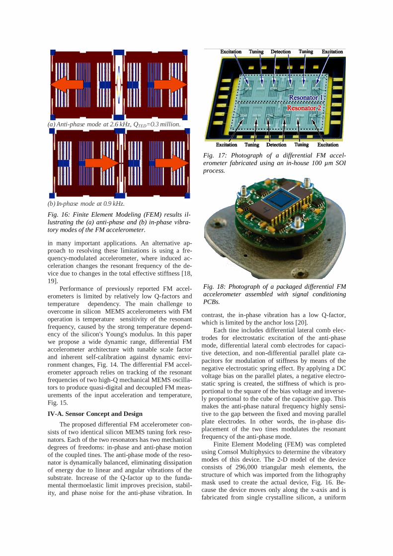
Finite Element Modeling (FEM) was completed
using Comsol Multiphysics to determine the vibratory
modes of this device. The 2-D model of the device
consists of 296,000 triangular mesh elements, the
structure of which was imported from the lithography
mask used to create the actual device, Fig. 16. Be-cause the device moves only along the x-axis and is
fabricated from single crystalline silicon, a uniform
Fig. 17: Photograph of a differential FM accel-
erometer fabricated using an in-house 100 µm SOI
process.
Fig. 18: Photograph of a packaged differential FM
accelerometer assembled with signal conditioning
PCBs.
(a) Anti-phase mode at 2.6 kHz, QTED=O.3 million.
(b) In-phase mode at 0.9 kHz.
Fig. 16: Finite Element Modeling (FEM) results il-
lustrating the (a) anti-phase and (b) in-phase vibra-
tory modes of the FM accelerometer.

Young's Modulus was used with a value of 160 GPa.
The in-phase and anti-phase resonance frequency
were found to be 0.9 kHz and 2.6 kHz, respectively.
Through the suspension system design, the next mode
of vibrations was pushed to 25 kHz frequency to min-
imize cross axis sensitivity. A second FEM model
was then executed to analyze the fundamental
thermoelastic limit of the Q-factor. For the anti-phase
mode of vibrations, a Q-factor of 0.3 million was pre-
dicted.
IV-B. Self-Calibration through Differential FM
The proposed temperature self-calibration ap-
proach takes advantage of the differential design, in
which both oscillators have the same sensitivity to
temperature but opposite sensitivity to external accel-
eration, Fig. 14 and 15. The dependency of frequency
on temperature has a well known linear relationship
for single crystalline silicon, enabling direct self-
sensing of temperature. The differential FM signal processing tracks the frequency difference between
the two resonant accelerometers, enabling drift free
measurement of acceleration, Fig. 15. In this ap-
proach, the FM accelerometer provides a quasi-digital
measurement of the input acceleration as well as di-
rect measurement of the accelerometer temperature.
The sensor becomes its own thermometer, eliminating
thermal lags and hysteresis typical in compensation
schemes using an external temperature sensor.
V-C. FM Accelerometer Characterization
The fabrication of prototype FM accelerometers was performed using an in-house, wafer-level, single
mask process. Devices were fabricated using Silicon-
on-Insulator (SOI) wafers with a 100 μm single crys-
talline silicon device layer, a 5 μm buried oxide layer,
and a 500 μm handle wafer, Fig. 17. After wafer fab-
rication and dicing, sensors were attached to a ceram-
ic DIP-24 package, wirebonded, and vacuum sealed
in-house at ~1 Torr. In future fabrication runs, accel-
erometers will be vacuum sealed at 0.1 mTorr using
getter to enable ultra-high Q-factor operation. For
testing, the packaged sensors were assembled with
signal conditioning electronics, Fig. 18.
A standard multi-point tumble test was carried
out for a single tuning fork (non-differential) FM ac-
celerometer using an Ideal Aerosmith 2102 Series
Two-Axis Position and Rate Table System. The sen-
sor was tested by measuring the change of the anti-phase resonant frequency as a function of inclination
angle with 10 o increments. The resonance frequency
of the accelerometer was recorded for each orientation
within a range from -g to g. This experiment was per-
formed for three different tuning voltages (28, 25 and
20 V), revealing linear response to acceleration with
tunable scale factors of 4.4, 2.0 and 1.2 Hz/g, respec-
tively, Fig. 19.
To evaluate the proposed self-calibration concept,
a differential FM accelerometer with two tuning fork
oscillators was placed into a TestEquity 107 tempera-ture chamber. The temperature was set to 70 °C for
the duration of 3 hours. The temperature control was
then turned off and the output signals from both tun-
ing forks were recorded Fig. 20. Each oscillator
showed an identical 500 mg drif over the temperature
change. Differential FM demodulation provided au-
tomatic calibration against temperature by canceling
common frequency drifts between the two sensors. As
shown in Fig. 21, the drift over temperature was re-
duced to approximately 1 mg, currently limited by the
noise performance of oscillators sealed with 1 Torr
Fig. 19: Measured input-output characteristic of FM
accelerometer for different stiffness modulation DC
voltages. Inset: scale factor vs. modulation DC volt-
age.
Fig. 20: Measured output of two differential FM
channels during dynamic temperature ramp. Bias
drifts track each other, enabling self-calibration.
Fig. 21: Measured differential FM output during a
dynamic temperature ramp, showing self-calibration
against temperature with a low drift rate of 30 µg/hr.
pressure. Testing of differential FM accelerometers
sealed with getter is expected to improve the bias sev-
eral orders of magnitude.
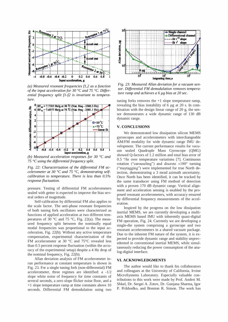
Self-calibration by differential FM also applies to
the scale factor. The anti-phase resonant frequencies
of both tuning fork oscillators were characterized as
functions of applied acceleration at two different tem-
peratures of 30 °C and 75 °C, Fig. 22(a). The meas-
ured frequency split between the nominally equal modal frequencies was proportional to the input ac-
celeration, Fig. 22(b). Without any active temperature
compensation, experimental characterization of the
FM accelerometer at 30 °C and 75°C revealed less
than 0.5 percent response fluctuation (within the accu-
racy of the experimental setup) despite a 4 Hz drop of
the nominal frequency, Fig. 22(b).
Allan deviation analysis of FM accelerometer in-
run performance at constant temperature is shown in
Fig. 23. For a single tuning fork (non-differential) FM
accelerometer, three regimes are identified: a -1/2
slope white noise of frequency for time constants of several seconds, a zero slope flicker noise floor, and a
+1 slope temperature ramp at time constants above 10
seconds. Differential FM demodulation using two
tuning forks removes the +1 slope temperature ramp,
revealing the bias instability of 6 µg at 20 s. In com-
bination with the design linear range of 20 g, the sen-
sor demonstrates a wide dynamic range of 130 dB
dynamic range.
V. CONCLUSIONS
We demonstrated low dissipation silicon MEMS
gyroscopes and accelerometers with interchangeable
AM/FM modality for wide dynamic range IMU de-
velopment. The current performance results for vacu-
um sealed Quadruple Mass Gyroscope (QMG)
showed Q-factors of 1.2 million and total bias error of
0.5 °/hr over temperature variations [7]. Continuous rotation (“carouseling”) and discrete ±180° turning
(“maytagging”) were implemented for true North de-
tection, demonstrating a 3 mrad azimuth uncertainty.
Once North has been identified, it can be tracked by
the same transducer using FM method of detection
with a proven 170 dB dynamic range. Vertical align-
ment and acceleration sensing is enabled by the pro-
posed resonant accelerometers, with accuracy ensured
by differential frequency measurements of the accel-
eration.
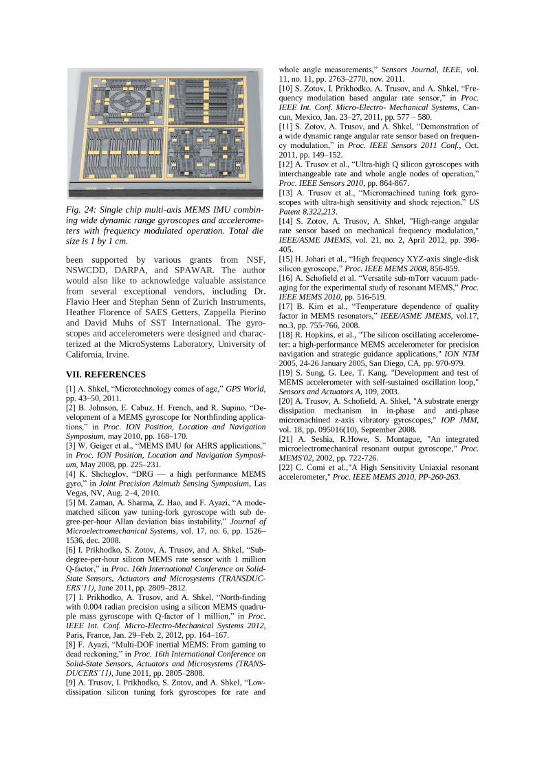
Inspired by the progress on the low dissipation
inertial MEMS, we are currently developing a multi-axis MEMS based IMU with inherently quasi-digital
FM operation, Fig. 24. Currently we are developing a
single-die system comprising a gyroscope and two
resonant accelerometers in a shared vacuum package.
Due to the inherent FM nature of the system, it is ex-
pected to provide dynamic range and stability unprec-
edented in conventional inertial MEMS, while simul-
taneously reducing the power consumption of the ana-
log-digital interface.
VI. ACKNOWLEDGMENTS
The author would like to thank his collaborators
and colleagues at the University of California, Irvine
MicroSystems Laboratory. Especially valuable con-
tributions to this work were made by Prof. Andrei M.
Shkel, Dr. Sergei A. Zotov, Dr. Gunjana Sharma, Igor
P. Prikhodko, and Brenton R. Simon. The work has
(a) Measured resonant frequencies f1,2 as a function
of the input acceleration for 30 °C and 75 °C. Differ-
ential frequency split f1-f2 is invariant to tempera-
ture.
(b) Measured acceleration responses for 30 °C and
75 °C using the differential frequency split.
Fig. 22: Characterization of the differential FM ac-
celerometer at 30 °C and 75 °C, demonstrating self-
calibration to temperature. There is less than 0.5%
response fluctuation.
Fig. 23: Measured Allan deviation for a vacuum sen-
sor. Differential FM demodulation removes tempera-ture ramp and achieves a 6 µg bias at 20 sec.
been supported by various grants from NSF, NSWCDD, DARPA, and SPAWAR. The author
would also like to acknowledge valuable assistance
from several exceptional vendors, including Dr.
Flavio Heer and Stephan Senn of Zurich Instruments,
Heather Florence of SAES Getters, Zappella Pierino
and David Muhs of SST International. The gyro-
scopes and accelerometers were designed and charac-
terized at the MicroSystems Laboratory, University of
California, Irvine.
VII. REFERENCES
[1] A. Shkel, “Microtechnology comes of age,” GPS World, pp. 43–50, 2011. [2] B. Johnson, E. Cabuz, H. French, and R. Supino, “De-velopment of a MEMS gyroscope for Northfinding applica-
tions,” in Proc. ION Position, Location and Navigation Symposium, may 2010, pp. 168–170. [3] W. Geiger et al., “MEMS IMU for AHRS applications,” in Proc. ION Position, Location and Navigation Symposi-um, May 2008, pp. 225–231. [4] K. Shcheglov, “DRG — a high performance MEMS gyro,” in Joint Precision Azimuth Sensing Symposium, Las Vegas, NV, Aug. 2–4, 2010.
[5] M. Zaman, A. Sharma, Z. Hao, and F. Ayazi, “A mode-matched silicon yaw tuning-fork gyroscope with sub de-gree-per-hour Allan deviation bias instability,” Journal of Microelectromechanical Systems, vol. 17, no. 6, pp. 1526–1536, dec. 2008. [6] I. Prikhodko, S. Zotov, A. Trusov, and A. Shkel, “Sub-degree-per-hour silicon MEMS rate sensor with 1 million Q-factor,” in Proc. 16th International Conference on Solid-
State Sensors, Actuators and Microsystems (TRANSDUC-ERS’11), June 2011, pp. 2809–2812. [7] I. Prikhodko, A. Trusov, and A. Shkel, “North-finding with 0.004 radian precision using a silicon MEMS quadru-ple mass gyroscope with Q-factor of 1 million,” in Proc. IEEE Int. Conf. Micro-Electro-Mechanical Systems 2012, Paris, France, Jan. 29–Feb. 2, 2012, pp. 164–167. [8] F. Ayazi, “Multi-DOF inertial MEMS: From gaming to dead reckoning,” in Proc. 16th International Conference on
Solid-State Sensors, Actuators and Microsystems (TRANS-DUCERS’11), June 2011, pp. 2805–2808. [9] A. Trusov, I. Prikhodko, S. Zotov, and A. Shkel, “Low-dissipation silicon tuning fork gyroscopes for rate and
whole angle measurements,” Sensors Journal, IEEE, vol. 11, no. 11, pp. 2763–2770, nov. 2011. [10] S. Zotov, I. Prikhodko, A. Trusov, and A. Shkel, “Fre-quency modulation based angular rate sensor,” in Proc. IEEE Int. Conf. Micro-Electro- Mechanical Systems, Can-
cun, Mexico, Jan. 23–27, 2011, pp. 577 – 580. [11] S. Zotov, A. Trusov, and A. Shkel, “Demonstration of a wide dynamic range angular rate sensor based on frequen-cy modulation,” in Proc. IEEE Sensors 2011 Conf., Oct. 2011, pp. 149–152. [12] A. Trusov et al., “Ultra-high Q silicon gyroscopes with interchangeable rate and whole angle nodes of operation,” Proc. IEEE Sensors 2010, pp. 864-867.
[13] A. Trusov et al., “Micromachined tuning fork gyro-scopes with ultra-high sensitivity and shock rejection,” US Patent 8,322,213. [14] S. Zotov, A. Trusov, A. Shkel, "High-range angular rate sensor based on mechanical frequency modulation," IEEE/ASME JMEMS, vol. 21, no. 2, April 2012, pp. 398-405. [15] H. Johari et al., “High frequency XYZ-axis single-disk
silicon gyroscope,” Proc. IEEE MEMS 2008, 856-859. [16] A. Schofield et al. “Versatile sub-mTorr vacuum pack-aging for the experimental study of resonant MEMS,” Proc. IEEE MEMS 2010, pp. 516-519. [17] B. Kim et al., “Temperature dependence of quality factor in MEMS resonators,” IEEE/ASME JMEMS, vol.17, no.3, pp. 755-766, 2008. [18] R. Hopkins, et al., "The silicon oscillating accelerome-
ter: a high-performance MEMS accelerometer for precision navigation and strategic guidance applications," ION NTM 2005, 24-26 January 2005, San Diego, CA, pp. 970-979. [19] S. Sung, G. Lee, T. Kang. "Development and test of MEMS accelerometer with self-sustained oscillation loop," Sensors and Actuators A, 109, 2003. [20] A. Trusov, A. Schofield, A. Shkel, "A substrate energy dissipation mechanism in in-phase and anti-phase micromachined z-axis vibratory gyroscopes," IOP JMM,
vol. 18, pp. 095016(10), September 2008. [21] A. Seshia, R.Howe, S. Montague, "An integrated microelectromechanical resonant output gyroscope," Proc. MEMS'02, 2002, pp. 722-726. [22] C. Comi et al.,"A High Sensitivity Uniaxial resonant accelerometer," Proc. IEEE MEMS 2010, PP-260-263.
Fig. 24: Single chip multi-axis MEMS IMU combin-
ing wide dynamic range gyroscopes and accelerome-
ters with frequency modulated operation. Total die size is 1 by 1 cm.