ultimatesteam & maintenance steam manifolds manual · multi-pipe/bottom feed - up to 500 lbs/hr...
TRANSCRIPT

ultimateSteam Short Absorption Steam Manifolds
Installation& Maintenance
Manual
Read and Savethese Instructions

CAREL UltimateSteam
2

Installation, Operating & Maintenance Manual
3
Table of Contents Product Model Numbers.........................................................................................................................................5 1: Installation ..........................................................................................................................................................6
1.1: Three Systems For Flexibility......................................................................................................................6 1.2: Locate The UltimateSteam Manifold...........................................................................................................7
1.2.1: To determine the UltimateSteam evaporation distance (English): ......................................................8 1.2.2: To determine the UltimateSteam evaporation distance (Metric): ........................................................9
1.3: Assemble and mount the ultimateSteam manifolds..................................................................................10 1.3.1: DS0 Single Manifold Models .............................................................................................................10 1.3.2: DSB Bottom Fed Manifold Models ....................................................................................................11
1.3.3: Assemble Vertical Manifolds..............................................................................................................11 1.3.4: Vertical Upright Insertion ...................................................................................................................11 1.3.5: Mounting The Manifolds ....................................................................................................................12 1.3.6: DST Top-Fed Models ........................................................................................................................15
1.4: Assemble control valve assembly.............................................................................................................17 1.5: Assemble strainer & trap assembly and valve assembly..........................................................................19
1.5.1: 1” Strainer & Trap Assembly .............................................................................................................19 1.5.2: 2” Strainer & Trap Assembly .............................................................................................................20
1.6: Connect control valve & trap to steam supply and manifold.....................................................................21 1.6.1: DS0 Single Manifold Models .............................................................................................................21 1.6.2: DSB/DST Multiple Manifold Models ..................................................................................................21
1.7: Final Plumbing of Steam Supply and Condensate Drains........................................................................22 1.7.1: Mount Valve Actuator.............................................................................................................................22
1.7.2: The DSA004E001 Electronic valve actuator .....................................................................................22 1.7.3: The DSA004E002 electronic valve actuator:.....................................................................................23 1.7.4: The DSA004P001 pneumatic valve actuator ....................................................................................23 1.7.5: The DSA004P002 pneumatic valve actuator ....................................................................................24 1.7.6: The DSA004P003 pneumatic valve actuator ....................................................................................24
1.8: Controls Installation...................................................................................................................................25 1.8.1 Controls Wiring ...................................................................................................................................26
1.9: Installation Checklist .................................................................................................................................30 2: Startup ..............................................................................................................................................................30 3: Operation..........................................................................................................................................................31 4: Maintenance.....................................................................................................................................................31 5: Trouble-Shooting..............................................................................................................................................31 6: Technical Specifications...................................................................................................................................33 7: Limited Warranty ..............................................................................................................................................33 IMPORTANT: BEFORE beginning installation:
• Check for shipping damage to cartons. Mark the shipping waybill accordingly • Open cartons and check for any hidden damage. Mark the shipping waybill accordingly. • Check packing slip to ensure all items have been received. Notify Carel LLC of any shortages or
damaged parts. You must notify Carel LLC within 5 working days of any shortages. IMPORTANT: The black coating on the ulimateSteam manifolds is insulation, NOT packing material. DO NOT SCRAPE IT OFF.
Copyright © 2005 by Carel USA, LLC. All rights reserved.

CAREL UltimateSteam
4

Installation, Operating & Maintenance Manual
5
Product Model Numbers
Model Selection
DS B H F 00000 DS = UltimateSteam Type Width Height Version
0=single pipe A=12 (300 mm) Internal Use Only
B=bottom fed B=18 (450 mm) B=18 (450 mm)
T=top fed C=24 (600 mm) C=24 (600 mm)
D=36 (900 mm) D=36 (900 mm)
E=48 (1200 mm) E=48 (1200 mm)
F=60 (1500 mm) F=60 (1500 mm)
G=72 (1800 mm) G=72 (1800 mm)
H=84 (2100 mm) H=84 (2100 mm)
I=96 (2400 mm) I=96 (2400 mm)
L=108 (2700 mm) L=108 (2700 mm)
M=120 (3000 mm) M=120 (3000 mm)
NOTE: DSB width starts at “B” length and DST width starts at “D” length. Each UltimateSteam unit is provided with a data label:
NOTE: MAX CAPACITY is the maximum capacity of the ultimateSteam manifold assembly. The actual capacity for any project is controlled by the valve orifice Cv.
ultimateSteam
ORDER CODE DSTGH00000
MAX. CAPACITY 2200 LBS/HR ( 1000 KG/HR)
SERIAL NUMBER U000036
MFG DATE 04/18/2006
CAREL UltimateSteam
6
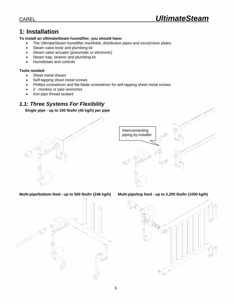
1: Installation To install an UltimateSteam humidifier, you should have:
• The UltimateSteam humidifier manifolds, distribution pipes and escutcheon plates • Steam valve body and plumbing kit • Steam valve actuator (pneumatic or electronic) • Steam trap, strainer and plumbing kit • Humidistats and controls
Tools needed:
• Sheet metal shears • Self-tapping sheet metal screws • Phillips screwdriver and flat blade screwdriver for self-tapping sheet metal screws • 2 - monkey or pipe wrenches • Iron pipe thread sealant
1.1: Three Systems For Flexibility Single pipe - up to 100 lbs/hr (45 kg/h) per pipe
Multi-pipe/bottom feed - up to 500 lbs/hr (246 kg/h) Multi-pipe/top feed - up to 2,200 lbs/hr (1000 kg/h)
Interconnecting piping by installer

Installation, Operating & Maintenance Manual
7
1.2: Locate The UltimateSteam Manifold Properly locating the UltimateSteam humidifier and its controls in your air handler or duct is very important - most steam absorption problems are the result of improper installation.
Locations:
A. BEST: locate far enough from elbow to be in laminar air flow. Maintain evaporation distance.
B. BEST: locate with enough distance for proper evaporation and to avoid turbulence from the fan.
C. GOOD: providing there is enough distance for proper evaporation from the humidifier manifold to the fan inlet (back of fan doesn’t really matter).
D. OK: providing there is enough distance for proper evaporation from the humidifier manifold to the heating coil (particularly if the heating coil is electric)
E. POOR: workable if the cooling coil is inactive during humidifier operation. An active cooling coil will remove the moisture the humidifier is trying to put in.
F. POOR: same problems as C&D plus the air may be very cold, increasing evaporation distance or causing condensation.
G. POOR: same problems as C, D, & E plus the filters may get wet producing an unsafe conditions with growth of biologicals.
H. POOR: only workable if the system is 100% recirculated air with no exhaust.
The following pages have nomographs and formulas for evaporation distance.
CAREL UltimateSteam
8
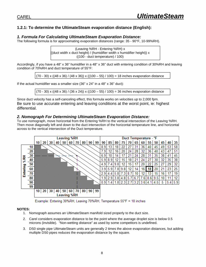
1.2.1: To determine the UltimateSteam evaporation distance (English): 1. Formula For Calculating UltimateSteam Evaporation Distance: The following formula is for approximating evaporation distances (range: 35 - 90°F, 10-99%RH).
(Leaving %RH - Entering %RH) x ((duct width x duct height) / (humidifier width x humidifier height)) x
((100 - duct temperature) / 100) Accordingly, if you have a 48” x 36” humidifier in a 48” x 36” duct with entering condition of 30%RH and leaving condition of 70%RH and duct temperature of 55°F:
(70 - 30) x ((48 x 36) / (48 x 36)) x ((100 – 55) / 100) = 18 inches evaporation distance If the actual humidifier was a smaller size (36” x 24” in a 48” x 36” duct):
(70 - 30) x ((48 x 36) / (36 x 24)) x ((100 – 55) / 100) = 36 inches evaporation distance Since duct velocity has a self-canceling effect, this formula works on velocities up to 2,000 fpm. Be sure to use accurate entering and leaving conditions at the worst point, ie: highest differential. 2. Nomograph For Determining UltimateSteam Evaporation Distance: To use nomograph, move horizontal from the Entering %RH to the vertical intersection of the Leaving %RH. Then move diagonally left and down to the duct intersection of the horizontal temperature line, and horizontal across to the vertical intersection of the Duct temperature.
NOTES:
1. Nomograph assumes an UltimateSteam manifold sized properly to the duct size.
2. Carel considers evaporation distance to be the point where the average droplet size is below 0.5 microns (invisible). “Non-wetting distance” as used by some competitors is undefined.
3. DS0 single pipe UltimateSteam units are generally 2 times the above evaporation distances, but adding multiple DS0 pipes reduces the evaporation distance by the square.

Installation, Operating & Maintenance Manual
9
1.2.2: To determine the UltimateSteam evaporation distance (Metric): 1. Formula For Calculating UltimateSteam Evaporation Distance: The following formula is for approximating evaporation distances (range: 1 - 32°C, 10-99%RH).
(Leaving %RH - Entering %RH) x ((duct width x duct height) / (humidifier width x humidifier height)) x
((100 – (1.8 x duct temperature + 32)) / 100) x 25.4 Accordingly, if you have a 1200mm x 900mm humidifier in a 1200mm x 900mm duct with entering condition of 30%RH and leaving condition of 70%RH and duct temperature of 13°C: (70 - 30) x ((1200 x 900) / (1200 x 900)) x ((100 – (1.8 x 13 + 32)) / 100) x 25.4 = 453mm evaporation distance
If the actual humidifier was a smaller size (900mm x 600mm in a 1200mm x 900mm duct):
(70 - 30) x ((1200 x 900) / (900 x 600)) x ((100 – (1.8 x 13 + 32)) / 100) x 25.4 = 906mm evaporation distance Since duct velocity has a self-canceling effect, this formula works on velocities up to 10 mps. Be sure to use accurate entering and leaving conditions at the worst point, ie: highest differential. 2. Nomograph For Determining UltimateSteam Evaporation Distance: To use nomograph, move horizontal from the Entering %RH to the vertical intersection of the Leaving %RH. Then move diagonally left and down to the duct intersection of the horizontal temperature line, and horizontal across to the vertical intersection of the Duct temperature.
NOTES:
1. Nomograph assumes an UltimateSteam manifold sized properly to the duct size. 2. Carel considers evaporation distance to be the point where the average droplet size is below 0.5
microns (invisible). “Non-wetting distance” as used by some competitors is undefined. 3. DS0 single pipe UltimateSteam units are generally 2 times the above evaporation distances, but adding
multiple DS0 pipes reduces the evaporation distance by the square.

CAREL UltimateSteam
10
1.3: Assemble and mount the ultimateSteam manifolds 1.3.1: DS0 Single Manifold Models The DS0 single manifold models do not require any manifold assembly. Generally the distributor manifolds should be mounted in the center of the air stream. Multiple pipes need to be evenly spaced to cover the duct surface area. SIDE VIEW
In vertical ducts, the distributor manifolds are mounted in the center with the slots facing up. The airflow may be up or down, but when the airflow is down, maximum velocity is 1,500 fpm (7.6 m/s).
300 mm 150 mm
Installation of the manifold into the duct is simple:
1. Bore a 2-1/2” (63.5 mm) diameter hole in the side of the duct;
2. Caulk the mounting plate facing the duct;
3. Insert the manifold through the hole and secure the mounting plate with sheet metal screws;
4. Secure the opposite end either by piercing the duct with a threaded rod, or by a hanging strap. End mounting stud is 3/8”-16. 12” & 18” (300 & 450 mm ) models do not have an end mounting stud) Drain connection is 1/2” MPT.

Installation, Operating & Maintenance Manual
11
1.3.2: DSB Bottom Fed Manifold Models 1.3.3: Assemble Vertical Manifolds The vertical distribution manifolds are inserted into the bottom feed header by hand (slip fit) and then into the top header if any. • Vertical slotted discharge
manifolds must be installed with the internal fishbone wick ends sloping up as in a “Y”.
• Do not force the vertical manifolds into the headers beyond the insulation.
• Do not use any lubricants. Manually reform the ends slightly if necessary.
• Insure discharge slots are perpendicular to the air flow.
• On DST models, run a bead of RTV silicone caulk around the junction of the vertical manifolds and top header.
The DSB models have the flexibility of being installed 2 different ways: 1) with the header underneath the duct and only the vertical manifolds in the duct, OR
2) with the entire assembly inside the duct. In air handler installations, clearance must be allowed at the bottom for the steam trap assembly as well as the p-trap draining the header.

CAREL UltimateSteam
12
1.3.4: Vertical Upright Insertion
The vertical uprights must be inserted 2.5” to 3” into the collar. A stop has been welded to the upright to prevent over-insertion.
Exposure up to ½” of bare metal on the uprights at the collar will not affect the performance of the unit.
For aesthetic purposes, black high temperature RTV silicone can be used to seal the upright to the collar and cover the bare metal.

Installation, Operating & Maintenance Manual
13
1.3.5: Mounting The Manifolds The DSB and DST systems are mounted to the duct or overhead support using bolts or threaded rod through the mounting clamps supplied with the humidifiers. A top support strap could also be used (for units with height of 36” (900 mm) or more), which fastens across the vertical manifolds and to the duct top or sides. (Strap not supplied by CAREL.) MAKE SURE HEADER IS LEVEL
The humidifier is generally installed in ducts so that the end of the header sticks out of the duct on the feed side. In air handlers, the entire assembly will be inside the air handler plenum. Keep a minimum of 6” (150 mm) from the last vertical discharge manifolds to the sides of the duct or air handler.
6” (150mm) DISTANCE BETWEEN DISTRIBUTOR TUBE
CENTERS

CAREL UltimateSteam
14
Installation Clamps for DST & DSB
Note: Threaded rod, nuts and other mounting hardware are provided by the installer. This design allows the UltimateSteam unit to be mounted from the bottom (as shown in the pictures below) or the clamps can be rotated and the unit can be mounted from the face of a coil.

Installation, Operating & Maintenance Manual
15
Air Handler Mounting
DSB Model
1.3.6: DST Top-Fed Models The DST models are assembled inside the duct or air handler if necessary, by mounting the bottom header first, then inserting the upright manifolds, then installing the top header and securing the assembly. The top and bottom headers are secured, as with the DSB models, either to the plenum top and bottom, or to Unistrut or hanging rods. Unit must be secured so that air velocity does not move it. NOTE: When the vertical upright steam discharge manifolds (slotted) are installed into the top header, you must run a bead of high temperature RTV silicone around the junction to seal it from dripping.
NOTE: When assembling the upright distributors into the bottom and top headers, always insert so that the attached arrow faces UP.

CAREL UltimateSteam
16
Air Handler Installation Installation of the UltimateSteam inside an air handler requires that the system be sized slightly smaller to allow for proper fall to the steam trap and clearances for the valves and actuators.
DST Model

Installation, Operating & Maintenance Manual
17
1.4: Assemble control valve assembly DS Valve kits are sold as separate items and include: (shipped unassembled)
Part Number Description Components
DSAK24V00A 1/2" valve size CV= 0.4 (2) 1/2" MPT x 3" nipples (2) 1/2" FPT x 1" MPT hex bushings 1" union
DSAK24V00B 1/2" valve size CV= 0.63 (2) 1/2" MPT x 3" nipples (2) 1/2" FPT x 1" MPT hex bushings 1" union
DSAK24V00C 1/2" valve sizes CV= 1 (2) 1/2" MPT x 3" nipples (2) 1/2" FPT x 1" MPT hex bushings 1" union
DSAK24V00D 1/2" valve sizes CV= 1.6 (2) 1/2" MPT x 3" nipples (2) 1/2" FPT x 1" MPT hex bushings 1" union
DSAK24V00E 1/2" valve sizes CV=2.5 (2) 1/2" MPT x 3" nipples (2) 1/2" FPT x 1" MPT hex bushings 1" union
DSAK24V00F 1/2" valve sizes CV=4 (2) 1/2" MPT x 3" nipples (2) 1/2" FPT x 1" MPT hex bushings 1" union
DSAK34V00G 3/4" valve size CV= 6.3 (2) 3/4" MPT x 3" nipples (2) 3/4" FPT x 1" MPT hex bushings 1" union
** NOTE: DSAK24V00* = standard valves, ie: brass and iron components up to 15 psi DSAK24VS0* = stainless steel valve trim and components up to 15 psi DSAK24V0H* = standard trim and components for 20 to 60 psi DSAK24VSH* = stainless steel valve trim and components for 20 to 60 psi
1/2” or 3/4” valve body
1/2” or 3/4” x 3” nipples (2)
1/2" or 3/4” FPT x 1" MPT hex bushing (2)
1” union

CAREL UltimateSteam
18
1-1/4” or 1-1/2” valve body
1-1/4 or 1-1/2” x 3” nipples 2” union
1-1/4” FPT x 2” MPT hex bushings (2)
Part Number Description Components
DSAK44V00H 1" valve size CV=10 (2) 1" MPT x 3" nipples 1" union
Part Number Description Components
DSAK54V00I 1 1/4" valve size CV= 16: (2) 1-1/4" MPT x 3" nipples (2) 1 1/4" FPT x 2" MPT hex bushings 2" union
DSAK64V00J 1 1/2" valve size CV= 25: (2) 1-1/2" MPT x 3" nipples (2) 1 1/2" FPT x 2" MPT hex bushings 2" union
Part Number Description Components
DSAK84V00K 2" valve size CV= 40: (2) 2" MPT x 3" nipples 2" union
1” valve body
1” x 3” nipple
1” x 3” nipple
1” union
2” valve body
2” x 3” nipples (2)
2” union

Installation, Operating & Maintenance Manual
19
1.5: Assemble strainer & trap assembly and valve assembly Using proper pipe thread sealant, assemble the supplied parts as shown. 1.5.1: 1” Strainer & Trap Assembly
Part Number Description Components
DSAK44T000 DSAK44TS00 (Stainless steel)
1'' Steam trap & strainer with plumbing kit
1” Y-strainer 1” x 6” nipple 1” x 90° FPT elbow 1” x 3” nipple 1” FPT tee 3/4” x 1” hex bushing (2) 3/4” x 6” nipples 3/4” FPT union 3/4” 90° street elbow 3/4” float & thermostatic trap
¾” FLOAT AND THERMOSTATIC
STEAM TRAP
1" Y-STRAINER
3/4" STREET ELBOW
1" x 90° FPT ELBOW
1" x 6" NIPPLE
1" x 3" NIPPLE
1" FPT TEE 3/4" X 1" HEX BUSHING
3/4" UNION 3/4" X 6" NIPPLES (2)

CAREL UltimateSteam
20
1.5.2: 2” Strainer & Trap Assembly
Part Number Description Components
DSAK84T000 DSAK84TS00 (Stainless steel)
2'' Steam trap & strainer with plumbing kit
2” Y-strainer (3) 2” x 6” nipple (2) 2” x 90° FPT elbow (2) 2” x 3” nipple 2” FPT tee 2” FPT union 2” float & thermostatic trap
2” FLOAT AND THERMOSTATIC
STEAM TRAP
2" Y-STRAINER
2" x 90° FPT ELBOW
2" x 90° FPT ELBOW
2" x 6" NIPPLE
2" x 3" NIPPLE
2" FPT TEE
2" UNION 2" X 6" NIPPLES (2)
Installation, Operating & Maintenance Manual
21
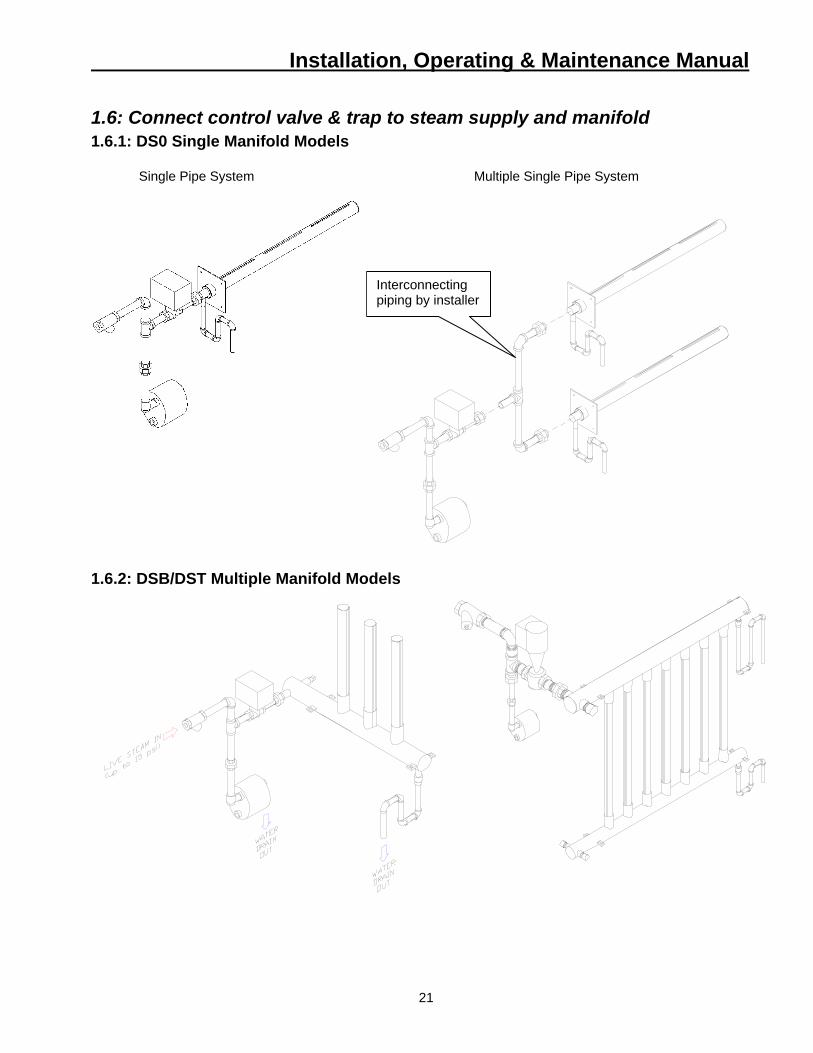
1.6: Connect control valve & trap to steam supply and manifold 1.6.1: DS0 Single Manifold Models
Single Pipe System Multiple Single Pipe System
1.6.2: DSB/DST Multiple Manifold Models
Interconnecting piping by installer

CAREL UltimateSteam
22
1.7: Final Plumbing of Steam Supply and Condensate Drains Run a steam line from the top of the steam supply header to the inlet strainer on the strainer/valve assembly. Be sure to install an isolation valve in the steam line leading to the humidifier. Follow standard steam piping codes and procedures, maintaining proper slopes. NOTE: Keep steam control valves as close to the distribution manifolds as possible. CAREL is not responsible for spitting due to excessive piping runs.
1.7.1: Mount Valve Actuator 1.7.2: The DSA004E001 Electronic valve actuator The DSA004E001 electronic valve actuator is designed to work with the steam control valves to provide proportional control of steam output.
WARNING: If mounting the actuator to a
valve already in line, close the valves in the piping (upstream first, then
downstream). Mounting the actuator to the valve: 1) Mount the actuator vertically above the valve. Mounting on either side is also acceptable, but do not mount the actuator upside-down below the valve. 2) If you are attaching the actuator to a new valve, remove the protective plastic cap from the valve stem. 3) Place the actuator on the valve. 4) Use a 1-1/4 inch open end wrench to tighten the coupling piece. 5) Use either a Phillips head screwdriver or a flat blade screwdriver to remove the actuator cover for access to the terminal block, selector plug, and jumper. 6) Attach wires, set the selector plug, and remove the R-M jumper, if necessary. Refer to wiring diagrams for your control scheme wiring. 7) Place the cover on the actuator. The position indicator must be at the "0" to fit into the shaft. If the cover does not fit easily, rotate it 180 degrees. All wiring must conform to NEC and local codes and regulations. Use earth ground isolating step-down Class 2 transformers. Do not use autotransformers. Determine the supply transformer rating by summing the VA of all actuators used. The maximum rating for Class 2 step-down transformer is 100 VA. It is recommended that no more than 10 actuators be powered by one transformer. To use a 4-20 mA signal, the circuit board jumper between R and M must be cut. If the circuit jumper between R and M is cut, you cannot wire the R and M terminals on the terminal block to re-establish the connection.

Installation, Operating & Maintenance Manual
23
1.7.3: The DSA004E002 electronic valve actuator: Is designed to work with the steam control valves to provide proportional control of steam output.
WARNING: If mounting the actuator to a valve already in
line, close the valves in the piping (upstream first, then downstream).
Mounting the actuator to the valve: 1) Remove the plastic cover from the top of the valve stem and bonnet: 2) Turn the control knob on top of the actuator to the MAN position; the small red tab pops out when in this position. Make sure the yoke nuts are loose enough to allow the actuator to slip over the bonnet. 3) Place the actuator onto the valve, putting the valve stem through the bottom of the actuator. 4) Guide the valve stem into the stem retainer of the actuator. 5) Hold the stem retainer in place as you tighten it around the valve stem. 6) Position the actuator to accommodate the wiring. Hold the actuator in place while tightening the yoke nuts. 7) Turn the control knob back to the AUTO position. 1.7.4: The DSA004P001 pneumatic valve actuator (shown attached to valve) The DSA004P001 pneumatic valve actuator is designed to work with the steam control valves to provide proportional control over relative humidity.
WARNING: If mounting the actuator to a
valve already in line, close the valves in the piping (upstream first, then
downstream). Mounting the actuator to the valve: 1) Remove the cardboard from the retaining ring in the lower housing. 2) Place the actuator on the valve bonnet and hand tighten. 3) If you need to change the orientation of the actuator, remove the retaining clip in the lower housing and rotate the actuator to the desired position. 4) Attach 1/4” (6 mm) poly tubing to the actuator.

CAREL UltimateSteam
24
1.7.5: The DSA004P002 pneumatic valve actuator is designed to work with steam valves from 1 1/4 to 2 inches in size to provide proportional control over humidity.
WARNING: If mounting the actuator to a valve
already in line, close the valves in the piping (upstream first, then downstream).
Do not install the actuator upside down: Mounting the actuator to the valve: 1) Remove the cardboard from the retaining ring in the lower housing. 2) Place the actuator on the valve bonnet and hand tighten. 3) If you need to change the orientation of the actuator, remove the retaining clip in the lower housing and rotate the actuator to the desired position. 4) Attach 1/4” (6mm) O.D. poly tubing to the actuator. 1.7.6: The DSA004P003 pneumatic valve actuator is designed to work with steam valves from 1 1/4 to 2 inches in size to provide proportional control over humidity.
WARNING: If mounting the actuator to a
valve already in line, close the valves in the piping (upstream first, then downstream).
Do not install the actuator upside down: Mounting the actuator to the valve: 1) Remove the cardboard from the retaining ring in the lower housing. 2) Place the actuator on the valve bonnet and hand tighten. 3) If you need to change the orientation of the actuator, remove the retaining clip in the lower housing and rotate the actuator to the desired position. 4) Attach 1/4” (6mm) O.D. poly tubing to the actuator.

Installation, Operating & Maintenance Manual
25
1.8: Controls Installation A typical humidifier control system includes a wall or return duct sensor or controller, a high limit duct humidistat, and an air proving switch. Placement of these devices is critical to proper operation of the overall system. The return air RH sensor must always be located BEFORE any outside air intake, in order to insure accurate sensing of the air from the space. Alternatively, a room RH sensor or humidistat can be used. Room sensors should be located on an inside wall or post and should not be hit by any discharge air streams from ducts. In a 100% outside air system, the RH sensor may be placed in the supply duct, at least 10 feet (3 m) down stream of the distributor pipe to act as both hi-limit and control. The airflow switch must be positioned to accurately open on a loss of air flow, to prevent the humidifier from running when there is no air to absorb the moisture. The hi-limit humidistat must be positioned far enough down stream of the steam distributor pipe(s) to prevent it from getting wet, but still allow it to accurately prevent overhumidification of the duct that could result in condensation. Cross Reference of CAREL part numbers to Siemens part numbers:
VALVES
CAREL Part No. Standard
2-15 psi (0.14-1 Bar)
Siemens Part No. Standard
2-15 psi (0.14-1 Bar)
CAREL Part No.
Standard 20-60 psi
(1.4-4 Bar)
Siemens Part No. Standard 20-60 psi
(1.4-4 Bar)
CAREL Part No.
Stainless Steel
2-15 psi (0.14-1 Bar)
Siemens Part No.
Stainless Steel
2-15 psi (0.14-1 Bar)
CAREL Part No.
Stainless Steel
20-60 psi (1.4-4 Bar)
Siemens Part No.
Stainless Steel
20-60 psi (1.4-4 Bar)
DSAK24V00A 599-02000C DSAK24VS0A 599-02015C DSAK24V00B 599-02002C DSAK24VS0B 599-02017C DSAK24V00C 599-02004C DSAK24V0HC 599-03072C DSAK24VS0C 599-02019C DSAK24VSHC 599-03072C DSAK24V00D 599-02006C DSAK24V0HD 599-03073C DSAK24VS0D 599-02021C DSAK24VSHD 599-03073C DSAK24V00E 599-02008C DSAK24V0HE 599-03074C DSAK24VS0E 599-02023C DSAK24VSHE 599-03074C DSAK24V00F 599-02010C DSAK24V0HF 599-03075C DSAK24VS0F 599-02025C DSAK24VSHF 599-03075C DSAK34V00G 599-02012C DSAK34V0HG 599-03076C DSAK34VS0G 599-02027C DSAK34VSHG 599-03076C DSAK44V00H 599-02014C DSAK44V0HH 599-03077C DSAK44VS0H 599-02029C DSAK44VSHH 599-03077C DSAK54V00I 599-03024 DSAK54V0HI 599-03078 DSAK54VS0I 599-03024 DSAK54VSHI 599-03078 DSAK64V00J 599-03025 DSAK64V0HJ 599-03079 DSAK64VS0J 599-03025 DSAK64VSHJ 599-03079 DSAK84V00K 599-03026 DSAK84VS0K 599-03026
ACTUATORS CAREL Part No. Siemens Part No.
DSA004E001 SQS65.5U DSA004E002 SKD62U DSA004P001 599-01088 DSA004P002 599-01083 DSA004P003 599-01050

CAREL UltimateSteam
26
1.8.1 Controls Wiring
ACTUATOR
AIRFLOW SWITCH
WALL-MOUNTED ON/OFF HUMIDISTAT
ON/OFFHUMIDISTAT
AIRFLOW SWITCH
DUCT-MOUNTED ON/OFF HUMIDISTAT
ON/OFFHUMIDISTAT
ACTUATOR

Installation, Operating & Maintenance Manual
27
ACTUATOR
AIRFLOW SWITCH
DDC OPERATED
ON/OFFDUCT HI-LIMIT

CAREL UltimateSteam
28
PC-301 Air Proving Switch Mounting the PC-301 air flow switch: Mount the airflow switch in the supply or return duct using the screws supplied. Mount the device so that the diaphragm is in a vertical position as shown at right. If the airflow switch is to be mounted on the return duct (vacuum), then mount it in a vertical position by the small plate. Drill a 7/16" (11 mm) hole in the side of the duct and connect the supplied tubing to the low pressure tap on the airflow switch and then run it through the drilled hole in the duct. Put no more than 2" (50 mm) of tubing into the duct. Caulk around the tubing where it enters the duct. The high-pressure tap is left open to atmosphere. If the airflow switch is to be mounted to the supply duct (pressure), then simply drill a 7/16” (11 mm) hole in the side of the duct, apply caulking to the large plate, and mount the device with the large plate to the duct and the high-pressure tap/tubing mated the hole. The low-pressure tap is left open to atmosphere. MOUNTING DIAGRAMS (English units)
TABLE 1. MAXIMUM ELECTRICAL SWITCH RATINGS Vac Full Load
Amps Locked Rotor
Amps Pilot Duty
(VA) Non-
Inductive Amps
24V - - 60 10 120V 6.25 37.5 300 10 240V 3.1 18.6 300 10 277V 2.7 16.2 300 10
WIRING DIAGRAM
N.C. Common Increase Pressure N.O. makes on increase N.O. in pressure.

Installation, Operating & Maintenance Manual
29
HC-101 and HC-201 Wall and Duct ON/OFF Humidistats Mounting the HC-101 room humidistat: Mount the HC-101 humidistat to an inside wall or post in the area to be humidified. Position it so that no drafts from registers or outlets are blowing on it. Be sure that it is not placed over a device that could generate heat or vapor ie: stove, machinery, cleaning vat. The unit has three wire leads, Orange, Brown and Red. Use the Orange and Brown leads for control operation. Use the Orange and Red leads for hi-limit operation. Mounting the HC-201 duct humidistat: Cut a hole in the side of the duct and mount the HC-201 humidistat to the duct, using the screws provided, at least 6 feet down stream of any live steam or mist. The unit has three wire leads, Orange, Brown and Red. Use the Orange and Brown leads for hi-limit operation. Wiring Diagram TABLE 1. SPECIFICATIONS Part No.
Type Scale Range %RH
Diff. %RH
OperatingLimits °F (°C)
Shipping & Storage °C (°F)
Connection Cover Dimensions mm (in.)
HC-101
Wall 10 to 90
5 40 to 125 (4 to 2)
-40 to 140 (-40 to 60)
6" (150 mm) color coded leads
Beige plastic
4-3/8 x 2-7/8 x 1-5/8
111 x 73 x 41 HC-201
Duct 15 to 95
5 40 to 125 (4 to 2)
-40 to 140 (-40 to 60)
Coded screw terminals
Metal 4-3/4 x 6-1/2 x 2-1/4
121 x 165 x 57 TABLE 2. MAXIMUM ELECTRICAL RATINGS
Part No. AC Volt 50/60 Hz
FLA LRA Resistive Amps
Pilot Duty VA
24 - - 8 60 120 7.2 43.2 8 345
HC-101 HC-201
240 3.6 21.6 8 345
Brown (N.O.)
Red (N.C.) Brown makes on Drop in R.H. drop in humidity Orange Common

CAREL UltimateSteam
30
1.9: Installation Checklist _____ 1. Humidifier properly assembled with all discharge slots facing the proper direction.
(Multipipe systems have the vertical slots in line with the manifolds, 90° to the air flow. Single pipe systems always have the slot facing up on top.)
_____ 2. Humidifier headers secured and level. _____ 3. Humidifier upright discharge manifolds plumb. _____ 4. Valve and trap assembly properly assembled and connected to the humidifier header. _____ 5. P-trap installed on discharge of each header. _____ 6. Steam feed line properly run, sloped and connected to the valve and trap assembly inlet. _____ 7. Controls properly wired.
2: Startup
1. Slowly open the steam isolation valve from the steam supply line. You should be able to hear steam running through the valve. Wait a few minutes for the steam to heat up the entire line to the humidifier and for all condensate to clear through the trap.
2. Verify that the steam trap on the valve/trap assembly of the humidifier is working properly - condensate
discharge line should be hot.
3. With air flowing in the duct or air handler, create a humidification demand by increasing the humidity control set point until it exceeds the actual humidity reading.
4. The valve on the humidifier should begin to open and steam should enter the humidifier manifolds.
5. Initially most of the steam will condense as it heats the manifolds. Insure that the P-traps on the
manifolds are clear and running to drain without leaking steam. NOTE: On first startup, some steam may leak from the P-traps on the manifolds if they have not been primed (filled with water).
6. Steam should begin exiting the humidifier manifolds.
7. Return the humidity control set point to the desired level.
Startup is complete.

Installation, Operating & Maintenance Manual
31
3: Operation The operation of the humidifier is simply to discharge steam into the duct or air handler as permitted by the opening and closing of the control valve. Control of the valve is from either the supplied humidistats and controls or from the Building Automation System.
4: Maintenance There is no maintenance on the humidifier manifold itself. Follow maintenance instructions for the control valve and actuator, supplied with those devices. Follow maintenance instructions for the traps, supplied with those devices.
5: Trouble-Shooting Water is spitting from the discharge manifolds.
1. The steam trap on the valve/trap assembly is not functioning. Clean or replace. 2. The header P-traps are not draining. Clean and check plumbing - must run to gravity drain. Check that
height of trap exceeds the static pressure of the duct/AHU, especially if under negative pressure. 3. The steam line has been taken from the bottom of the steam source or is not sloped properly. Change
line to take off from the top and check proper slopes. 4. The steam main is overloaded with water. Locate cause and correct. 5. Vertical discharge manifolds are not plumb. Make plumb. 6. Horizontal headers are not level. Make level. 7. Vertical discharge manifolds are installed upside down. Reinstall correctly. 8. Check valve sizing to maximum manifold capacity. Resize valve within manifold capacity.
Steam does not discharge from the manifolds when the valve is open.
1. Verify that valve is open. Correct. 2. Verify that steam is available and valves are open. Correct. 3. Verify that the steam pressure has not changed. Too high pressure could jam the valve. 4. Carefully place a mirror or metal object close to one of the steam discharge slots. If it fogs, steam is
discharging, but evaporating very quickly. No problem. DO NOT EVER PLACE YOUR HAND OVER OR NEAR THE STEAM DISCHARGE SLOTS.
5. Y-strainer may be clogged. Clean or replace. Steam valve will not open.
1. Verify power or air pressure to the valve actuator. Correct. 2. Verify control signal or pressure range to the valve actuator. Correct. 3. Verify control signal polarity to the valve actuator. Correct. 4. Remove actuator and test to see if it operates. Valve may be jammed - clean or replace. 6. Verify that the steam pressure has not changed. Too high pressure could jam the valve. 7. Verify proper valve orientation - electric valves must face up.
Steam valve will not close.
1. Verify control signal to the valve actuator. Correct. 2. Verify control signal polarity to the valve actuator. Correct. 3. Remove actuator and test to see if it operates. Valve may be jammed - clean or replace. 4. Verify that the steam pressure has not changed. Too high pressure could jam the valve. 5. Verify proper valve orientation - electric valves must face up.

CAREL UltimateSteam
32
Steam valve is leaking.
1. Verify full range control signal to the valve actuator. Correct. 2. Verify control signal polarity to the valve actuator. Correct. 3. Remove actuator and test to see if it operates. Valve may be jammed - clean or replace. 4. Verify that the steam pressure has not changed. Too high pressure could jam the valve.
Humidity exceeds set point.
1. Verify full range control signal to the valve actuator is compatible. Correct. 2. Verify control signal polarity to the valve actuator. Correct. 3. Check calibration of controller. Correct. 4. Insure humidity sensors are installed correctly and not located in drafts (wall). Correct. 5. Remove actuator and test to see if it operates. Valve may be jammed - clean or replace. 6. Verify that the steam pressure has not changed. Too high pressure could cause valve to leak. 7. Verify stable boiler pressure. Wide swings in pressure could be fighting the humidity controls. 8. From BAS system, change to P type control (not PI or PID).
Humidity remains below set point.
1. Verify full range control signal to the valve actuator is compatible. Correct. 2. Verify control signal polarity to the valve actuator. Correct. 3. Check calibration of controller. Correct. 4. Insure humidity sensors are installed correctly and not located in drafts (wall). Correct. 5. Remove actuator and test to see if it operates. Valve may be jammed - clean or replace. 6. Verify that the steam pressure has not changed. Too high pressure could jam valve. Too low will not
meet capacity. 7. Verify stable boiler pressure. Wide swings in pressure could be fighting the humidity controls. 8. From BAS system, change to P type control (not PI or PID). 9. Check that air flow switch is not fluttering. Correct. 10. Check that hi-limit controller is not located too close to steam discharge manifolds. Correct. 11. Humidifier is undersized. Check humidity load calculations.
Condensate in duct.
1. Verify humidifier capacity versus air volume. 2. See first item in trouble-shooting section of this manual. 3. Verify that hi-limit controller is working. Correct. 4. Verify evaporation distance to obstructions or elbows. Correct. 5. Verify steam valve is not leaking. Correct. 6. Uninsulated duct may be running through an area where ambient temperature is below internal duct
dew point. Insulate duct externally. Steam leaks from P-traps.
1. Check that height of trap exceeds the static pressure of the duct/AHU, especially if under negative pressure. Correct.
2. Check valve sizing to maximum manifold capacity. Resize valve within manifold capacity. 3. Check that inlet steam pressure does not exceed what the humidifier was ordered for.

Installation, Operating & Maintenance Manual
33
6: Technical Specifications Distributor Construction: Type 316 Stainless Steel Insulation: Proprietary high R value pliable coating, plenum safe, non-toxic Maximum temperature: 500°F (260°C) Maximum manifold pressure: 1 psi (6.9kpa) Control valves (standard = brass):
Electric: Siemens or other, full pressure drop Pneumatic: Siemens or other, full pressure drop
(Carel uses Siemens valves as standard with maximum 15 psi (1 bar) inlet pressure Steam traps: float & thermostatic standard, inverted bucket when inlet pressure exceeds 15 psi (1 bar) (Carel uses Barnes & Jones traps as standard) (Standard components are black iron) NOTE: stainless steel and high pressure components are by special order only.
7: Limited Warranty All products manufactured by Carel USA, LLC are warranted to the original purchaser to be free from defects in materials and workmanship in the course of normal and reasonable use for a period of 2 years and 1 month from the date of shipment (The OEM controls warranty is 2 years from date of manufacture), humidifier replacement parts warranty is 90 days from date of Invoice. Warranty replacement parts are warranted for remainder of original unit warranty or 90 days, whichever is longer, so long as the product has been installed and operated in accordance with all appropriate manuals and wiring diagrams, and started up by a qualified Carel USA technician. Any product or part that is found to be defective will, at the option of Carel USA, LLC be replaced or repaired. Carel USA, LLC reserves the right to inspect any part or installation before replacing or repairing defective parts. After startup of the product, labor for repairs or replacement of parts is not covered by this warranty. Products not included in this warranty are NTC and PTC probes, transformers (TRA series), and routinely replaceable parts such as steam cylinders and gaskets. Carel USA, LLC assumes no liability for consequential or inconsequential damage, or damage due to negligence or improper use. Under the terms of this warranty, the original purchaser may have certain legal rights and other rights, which may vary from state to state. The Warranty will not be considered valid if a product is damaged due to negligence, mishandling or misapplication, or if the product label is missing. Carel USA will attempt to repair or replace the products within two (2) months of the receipt of the returned goods.

CAREL UltimateSteam
34

Installation, Operating & Maintenance Manual
35

CAREL UltimateSteam
36
CAREL SpA Via dell'Industria, 11 - 35020 Brugine - Padova - Italy Phone: (+39)049 9716611 - Fax: (+39)049 9716600 e-mail: [email protected] - www.carel.com CAREL Australia Pty Ltd PO BOX 6809, Silverwater Bus. Ctr 1811 N.S.W. Australia Unit 37, 11-21 Underwood Road, Homebush N.S.W. 2140 Phone: (+61)2-8762 9200 - Fax: (+61)2-9764 6933 e-mail: [email protected] - www.carel.com.au CAREL Deutschland GmbH Am Spielacker, 34 - 63571 Gelnhausen - Germany Phone: (+49)6051 96290 - Fax: (+49)6051 962924 e-mail: [email protected] - www.carel.de
CAREL Sud America Ltda. Avenida Dourado, 578 - Cep. 13.280-000 Vinhedo - SP - Brazil Phone: (+55)19 38 26 25 65 - Fax: (+55)19 38 26 25 54 e-mail: [email protected] - www.carel.com.br
CAREL Asia Pacific Ltd. rm. - 8 F Shatin Galleria, 18 Shan Mei St., Fotan, Shatin - Hong Kong Phone: (+852)2947 7922 - Fax: (+852)2947 7660 e-mail: [email protected] - www.carelhk.com
CAREL China Ltd. Rm. 11, 8/F., Shatin Galleria, 18 Shan Mei St., Fotan, Shatin - Hong Kong Phone: (+852)2693 6223 - Fax: (+852)2693 6199 e-mail: [email protected] - www.carelhk.com
CAREL France Sas 32, Rue du Champ Dolin - 69800 Saint Priest - France Phone: (+33)472 47 88 88 - Fax: (+33)478 90 08 08 e-mail: [email protected] - www.carelfrance.fr
CAREL U.K. Ltd. Unit 6, Windsor Park Industrial Estate - 50 Windsor Avenue Merton, SW19 2TJ - London - United Kingdom Phone: (+44)208 545 9580 - Fax: (+44)208 543 8018 e-mail: [email protected] - www.careluk.co.uk
CAREL USA, LLC
385 S. Oak Street Manheim, PA 17545
+03U400105 Rev. 1.2