ultiflame aleesia/asencio electric fires
TRANSCRIPT
Ultiflame Aleesia/Asencio
Electric Fires
Model No’s:
B-1009635, B-1009636
CEULALRE, CEULASRE
Packing Checklist
Electric Fire Remote Control Handset* Log Set Ember Ice Set Instruction Manual Glass Suction Clamp Downlight Kit (Limestone suite models only)
*THIS PRODUCT REQUIRES 2 X AAA BATTERIES FOR USE IN THE HANDSET (NOT SUPPLIED)
IMPORTANT
PLEASE READ THESE INSTRUCTIONS CAREFULLY BEFORE INSTALLATION AND USE OF THIS ELECTRIC FIRE AND RETAIN
FOR FUTURE REFERENCE.
This appliance is not intended for use by persons (including children) with
reduced physical, sensory or learning disabilities, or lack of experience
and knowledge, unless given supervision or instruction concerning use of
the appliance by a person responsible for their safety.
Page 1

IMPORTANT SAFETY ADVICE
WHEN USING AN ELECTRICAL APPLIANCE, BASIC PRECAUTIONS SHOULD ALWAYS BE FOLLOWED TO REDUCE THE RISK OF FIRE, ELECTRIC SHOCK AND INJURY TO PERSONS, INCLUDING THE FOLLOWING IMPORTANT SAFETY ADVICE.
DO NOT cover or obstruct the airflow to the front of the heater. This is to avoid over-heating of the product.
DO NOT leave the heater unattended while it is in use. Always turn the appliance to the OFF position and switch off at the mains socket when not in use.
DO NOT leave children unsupervised whilst the appliance is switched on.
DO NOT operate this appliance with a damaged cord or plug, or after the appliance malfunctions, has been dropped or damaged in any way.
DO NOT install a timer switch to operate the appliance.
DO NOT use this appliance as a freestanding appliance. It must always be securely fixed into a Chimney breast opening.
DO NOT insert or allow objects to enter any ventilation or exhaust openings on the appliance. To prevent a possible fire do not block air intakes or exhaust openings in any manner.
DO NOT place this appliance near flammable materials, surfaces or substances, as there may be a risk of fire. Keep flammable materials, surfaces or substances at least 1 metre away from the front of the product.
DO NOT switch on the fire if volatile vapours are present in the room.
DO NOT use this appliance in any areas where petrol, paint or other flammable liquids are stored
e.g. a garage or a workshop as the appliance contains components capable of producing a spark.
DO NOT let bare skin touch any hot surfaces to avoid burns and personal injury. The heater vent will get hot when in use.
DO NOT use outdoors.
CAUTION- Some parts of this product can become hot and cause burns. Particular attention has to be given where children and vulnerable people are present.
This appliance is for household use only
Page 2

Product Technical Data Sheet
Supplier Name / Trademark CELSI
Supplier Model Identifier B-1009635 ALEESIA, B-1009636 ASENCIO
Voltage 230v AC 50HZ
Fuse 13 Amp
Nominal Heat Output (Measured) 1.6 kW
Minimum Heat Output (Indicative) 0.8 kW
Maximum Continuous Heat Output 1.6 kW
Auxiliary Electricity Consumption at Nominal Heat Output 0.016 kW
Auxiliary Electricity Consumption at Minimum Heat Output 0.016 kW
Auxiliary Electricity Consumption at Standby Mode 0.0005 kW
Type of heat Output / Room Temperature Control With electronic room temperature
control plus week timer
Other Control Options
With adaptive start control
Manufacturers Name and Address
BFM Europe Ltd. Gordon Banks Drive, Trentham Lakes, Stoke-on-Trent, Staffs, ST4 4TJ Tel: 01782 339000
Asencio
Aleesia
Page 3

Unpacking
Remove and discard the plastic bag.
Be responsible when handling the packing materials. Keep the original packaging for future transportation and/or storage.
Check all accessories are removed from the packaging before storing it away for future use.
KEEP PLASTIC BAGS AWAY FROM CHILDREN!
Choosing a suitable location
This electric fire is designed to be fitted within an existing brick / masonry chimney breast which must be dry with the chimney capped off using a suitable chimney cap.
The appliance must be kept away from any source of damp or moist conditions. Avoid any close contact with water.
Important Notice: To reduce heat losses and to prevent any chimney up draught
affecting the operation of your fire we recommend that the chimney is blocked off.
The chimney breast, wall or fireplace must be of sound construction and all fixings used must be suitable for the type of wall. If there is any doubt regarding the suitability of the installation site please contact your supplier.
From the front of the fire ensure that there is a minimum clearance of 50mm between any non-combustible materials. For combustible material clearances please consult with the manufacturer.
The fire can be connected direct or plugged into a mains socket which can be sited on the right hand side of the fire.
Ensure that the plug socket-outlet connection for this appliance is accessible. It MUST be readily accessible for easy electrical isolation in the event of servicing and replacing components etc. This appliance MUST NOT be located immediately below an electrical socket-outlet.
Page 4

Installation
Please refer to the relevant installation instructions applicable to the model fire purchased. Installation must be carried out by a qualified and competent person.
The opening sizes required to install the fires are
Asencio
H : 765mm
W : 600mm
D : 185mm
Aleesia
H : 685mm
W : 800mm
D : 185mm
Connect the appliance to single-phase AC supply of the voltage specified on the rating plate.
Should the fire be connected directly into the mains supply, then a fused switched spur with a 13 amp fuse must be fitted. It is imperative that the power supply is capable of handling a load of 2000 watts (2kw). This appliance must be earthed. Allow sufficient flex to enable the fire to be removed from the wall. Do not use an extension lead
IMPORTANT NOTE: Models which have LED downlights included in the suite / surround will require an additional mains supply. If wired directly into the mains supply, then a fused switched spur with a 3 amp fuse must be fitted ensuring that the plug socket-outlet connection is accessible. It MUST be readily accessible for easy electrical isolation in the event of servicing and replacing components etc.
Always ensure that all electrical work complies with the relevant Building Regulations and the Electrical Code of Practice. All electrical work should be carried out by a qualified electrician.
Ultiflame Asencio & Aleesia Wall Mounting
The base of the fire opening must be solid, level and firmly fixed to safely support the weight of the fire.
The fire is held in place using
4 suitable screws and
fasteners in the 4 fixing holes
on the sides of the appliance.
4 x Fixing Holes
Page 5

A false studded chimney breast can be built with a plastered finish to encase the fire
The chimney wall can now be finished with plasterboard or an alternative facing material which terminates at the facing trim.
The fire can be fitted direct into the chimney breast and plastered flush up to the facing trim
Ultiflame Asencio & Aleesia with Trim option
Installation is the same principle as wall mounting but the fire is screwed to the plastered wall to ensure that the facing trims protrude from the fire. For fitting of the trim please refer to the instructions included with the trim.
Height of Fire when installed with stone surrounds
Page 6

INSTALLING THE “ASENCIO” SURROUND
1. Unpack the surround from the wooden crate, check all parts are present and carefully store the components.
Contents of Asencio surround:- 1 off hearth panel 1 off R/H leg 1 off L/H leg 1 off R/H infill section 1 off L/H infill section 1 off bottom infill section 1 off top infill section 1 off shelf top infill section 1 off shelf
2. The underside of the hearth should be painted with a weak PVA (8 parts water to 1 part PVA). This will prevent staining penetrating through the stone. The hearth must be centred to the opening. If the fireplace is to be installed on a chimney breast ensure that the opening is also centred to the chimney breast. It is essential that the hearth is completely level. The hearth must be bedded down on bonding or an equivalent material. Avoid cement based products and ensure the hearth is firmly fitted and well supported. Allow the bedding material to set before any weight is placed onto the hearth. Wipe off any surplus bonding material with a wet sponge.
3. Fit bottom section to hearth, ensure it is central before fixing with a suitable mastic adhesive.
4. Fit brackets to top of legs, offer leg up to wall and mark position of fixing hole on wall, use shelf to ensure legs are correctly spaced / positioned. Remove shelf then cover hearth with dust sheet and drill the fixing holes. Remove the brackets from the legs, fix the side infills into place with suitable adhesive and secure the leg fixing brackets only to the wall. Fit legs to brackets that have been securely attached to the wall with fixings as detailed in Point 5.
5. Assess the chimney breast onto which the fire is to be installed and ensure that it is of sound construction and suitable for supporting the weight of the surround. Fixings used to secure the leg brackets to the masonry of the chimney breast shall be of expansive stainless steel or galvanised steel type masonry fixings for dense concrete blockwork or brickwork. Where fixings are located into light weight blockwork or friable aggregate blocks, the fixings shall be of the resin anchor type.
Page 7

6. Fix the shelf top infill section and shelf infill into place again utilising the same procedure as for the legs, i.e. mark positions, drill holes to suit, remove brackets and secure brackets to wall with suitable fixings as detailed in Point 5.
7. Fit shelf top section into place ensuring it is correctly centred, mark the position of holes for securing brackets on wall, remove shelf and drill wall and insert fixings in accordance with Point 5, these brackets can be recessed if required.
8. Ensure that the surround components as shown below are mechanically secured as indicated, this is required in accordance with the latest revision of BS 1251 : 2015 Open Fireplace Components.
9. Once the fireplace is correctly installed, grout all of the joints including between the fireplace and the wall with a water based cream mastic or tile grout. Ensure all surplus grout is immediately removed by washing the stonework using a sponge and clean water.
Page 8

INSTALLING THE “ALEESIA” SURROUND
1. Unpack the surround from the wooden crate, check all parts are present and carefully store the components.
Contents of Aleesia surround:- 1 off hearth panel 1 off R/H leg 1 off L/H leg 1 off R/H infill section 1 off L/H infill section 1 off bottom infill section 1 off top infill section 1 off shelf top infill section 1 off shelf 1 off Stub Hearth
1 off Down Lighting Kit (not shown) includes
2 off MR11 2.4W 3000K LED Bulbs
2 off chrome downlights
1 off wiring Loom
1 off Remote handset
1 off 23A 12V Battery (A23)
1 off Handset wall bracket
Page 9
2. The underside of the hearth should be painted with a weak PVA (8 parts water to 1 part PVA). This will prevent staining penetrating through the stone. The hearth must be centred to the opening. If the fireplace is to be installed on a chimney breast ensure that the opening is also centred to the chimney breast. It is essential that the hearth is completely level. The hearth must be bedded down on bonding or an equivalent material. Avoid cement based products and ensure the hearth is firmly fitted and well supported. Allow the bedding material to set before any weight is placed onto the hearth. Wipe off any surplus bonding material with a wet sponge.
3. Fit bottom section to hearth, ensure it is central before fixing with a suitable mastic adhesive.
4. Fit brackets to top of legs, offer leg up to wall and mark position of fixing hole on wall, use shelf to ensure legs are correctly spaced / positioned. Remove shelf then cover hearth with dust sheet and drill the fixing holes. Remove the brackets from the legs, fix the side infills into place with suitable adhesive and secure the leg fixing brackets only to the wall. Fit legs to brackets that have been securely attached to the wall with fixings as detailed in Point 5.
5. Assess the chimney breast onto which the fire is to be installed and ensure that
it is of sound construction and suitable for supporting the weight of the
surround. Fixings used to secure the leg brackets to the masonry of the
chimney breast shall be of expansive stainless steel or galvanised steel type
masonry fixings for dense concrete blockwork or brickwork. Where fixings are
located into light weight blockwork or friable aggregate blocks, the fixings shall
be of the resin anchor type
6. Fix the shelf top infill section and shelf infill into place again utilising the same procedure as for the legs, i.e. mark positions, drill holes to suit, remove brackets and secure brackets to wall with suitable fixings as detailed in Point 5.
7. Safely route the lighting kit wiring up to the surround shelf infill level ensuring that the wiring is kept clear of the fire and not trapped.
8. Remove the round locking clip from inside the chrome down lighter and fit the supplied LED bulb. Refit the locking ring inside to keep the bulb in place. Repeat for the second down lighter.
9. Fit the 2 down lighters from the underside of the shelf top infill header, by lifting the spring clamps and fitting into the two holes in the Shelf top infill
10. Once fitted in place connect the 2 bulbs using the two connectors on the wiring loom and
ensure the wiring, remote receiver unit and power unit are safely routed in the surround
11. Fit the supplied battery in the remote control handset and switch on power to the downlights. Check the lighting works correctly with the remote control. If required move the position of the remote receiver unit and aerial wire to ensure good signal coverage. After checking the lighting switch off the power before proceeding.
Page 10

12. Fit shelf top section into place ensuring it is correctly centred, mark the position of holes for securing brackets on wall, remove shelf and drill wall and insert fixings in accordance with Point 5, these brackets can be recessed if required.
13. Ensure that the surround components as shown below are mechanically secured as
indicated, this is required in accordance with the latest revision of BS 1251 : 2015
Open Fireplace Components.
14. Place the stub hearth in position between the legs of the fire surround and on top of
the hearth panel.
15. Once the fireplace is correctly installed, grout all of the joints including between the fireplace and the wall with a water based cream mastic or tile grout. Ensure all surplus grout is immediately removed by washing the stonework using a sponge and clean water.
Page 11

Front Glass Removal
To gain access to the Log Bed base remove front glass panel as shown below. Place glass
suction tool onto glass panel then remove 4 off side cheek fixing screws. Remove 2 off screws
from top glass clamp, making sure that the glass panel does not fall forward.
Glass Clamp Fixing Screws
Glass Clamp
Side Cheek Side Cheeks
Fixing Screws
Page 12

Laying the Log & Embers
The Logs and the Ember Ice are packed in a box within the fire. Take care when unpacking the Logs and the Ember Ice. Scatter the Ember Ice over the Log Bed Base making sure the black and clear embers are mixed evenly. Lay the Logs on top of the Ember Ice as shown in the pictures below.
Ultiflame VR Aleesia
1 2
3
Log Chippings
Total Logs = 5
x1 of log 1 x2 of log 2 x2 of log 3
Page 13

Ultiflame VR Asencio
1 2
3 4
Log Chippings
Total Logs = 5
x1 of log 1 x1 of log 2 x2 of log 3 x1 of log 4
Page 14
Operating the Fire
Manual Control
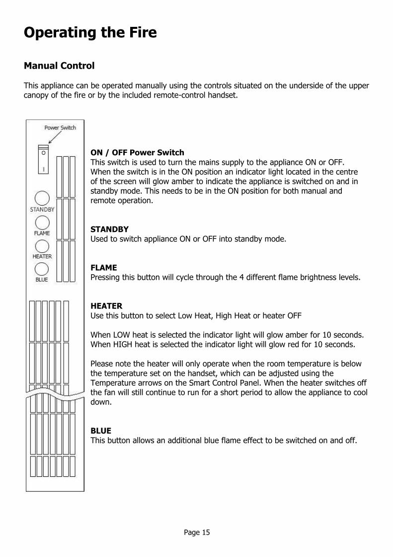
This appliance can be operated manually using the controls situated on the underside of the upper canopy of the fire or by the included remote-control handset.
ON / OFF Power Switch
This switch is used to turn the mains supply to the appliance ON or OFF. When the switch is in the ON position an indicator light located in the centre of the screen will glow amber to indicate the appliance is switched on and in standby mode. This needs to be in the ON position for both manual and remote operation.
STANDBY
Used to switch appliance ON or OFF into standby mode.
FLAME
Pressing this button will cycle through the 4 different flame brightness levels.
HEATER
Use this button to select Low Heat, High Heat or heater OFF
When LOW heat is selected the indicator light will glow amber for 10 seconds. When HIGH heat is selected the indicator light will glow red for 10 seconds.
Please note the heater will only operate when the room temperature is below the temperature set on the handset, which can be adjusted using the Temperature arrows on the Smart Control Panel. When the heater switches off the fan will still continue to run for a short period to allow the appliance to cool down.
BLUE
This button allows an additional blue flame effect to be switched on and off.
Page 15

Remote Control
Remove the battery / control panel cover by sliding completely down and insert 2 x AAA batteries ensuring the batteries are fitted correctly. Refit the cover by sliding back up to the original position. Please ensure old batteries are disposed of responsibly by contacting your local authority about recycling schemes.
Ensure that the ON / OFF Power Switch on the fire is in the ON position.
Point the remote-control handset directly towards the fire and press the appropriate button to operate the fire. Sliding the door down on the remote control will reveal the Smart Control panel which offers additional functions. Otherwise using the basic remote buttons will operate the fire in the same way as the manual control buttons with the exception of the blue flame function which can only be operated manually on the fire.
Page 16

Smart Control functions
The Smart Control panel reveals additional buttons to allow the following functions
Set the Time of day Thermostatic temperature adjustment from 16 to 30°C Set 7-day timer with up to 3 programmable periods per day Turn Adaptive Control On or Off Turn Off and clear timer settings
Setting the Time
1. Press the SYNC button, which will start the day cursor to blink. Using the time arrow buttons set to the current day e.g. Monday – 1, Tuesday – 2, Wednesday – 3 etc. Press SELECT to confirm the required day.
2. The hour setting will now be blinking, adjust using the time arrow buttons to the desired hour and confirm using the SELECT button.
3. The minute setting will now be blinking, adjust using the time arrow buttons to the desired minutes and confirm using the SELECT button.
Adjusting the desired temperature
Whilst the fire is switched on, use the Temperature Arrows to set the desired room temperature. A confirmation beep will be heard from the fire. If the room is already warmer than the temperature set then the heater will switch off until the thermostatic sensor detects a fall in temperature.
Setting the Timer function
The timer function allows up to 3 timers to be programmed for use over a 7 day period.
1. Press the TIMER button to display the first timer, and then press the SELECT button to adjust Timer 1 programme.
Set Time ON
2. The hour setting will now be blinking, adjust using the time arrow buttons to the desired hour to switch on the fire and confirm using the SELECT button.
3. The minute setting will now be blinking, adjust using the time arrow buttons to the desired
minutes to switch on the fire and confirm using the SELECT button.
4. The day cursor will now be blinking, use the time arrow buttons to highlight the required day and press SET, additional days can be added using the time arrows and SET buttons. If you add a day in error, select the day and press the CANCEL button to unselect. Only when you have set all the days you require for the timer press SELECT to
confirm. Set Time OFF (this must be at least 30 minutes after the ON time)
5. The hour setting will now be blinking, adjust using the time arrow buttons to the desired hour to switch off the fire and confirm using the SELECT button.
6. The minute setting will now be blinking, adjust using the time arrow buttons to the desired minutes to switch off the fire and confirm using the SELECT button.
7. A confirmation beep will be heard from the fire to confirm Timer 1 programme is now set.
Page 17

To set Timer 2 & 3 or alter timer programme. 8. Repeatedly pressing the TIMER button will cycle through the 3 available timer programmes
displaying the set parameters. To change or set an additional timer programme choose the Timer number required and press the SELECT button.
9. Set the timer programme as before following steps 2 to 7.
Switch Off and clear Timers
When the timer icon is displayed on the remote-control handset the timer function is active. To switch off the timer function and clear all timer programmes press the TIMER OFF button. A confirmation beep will be heard from the fire.
Adaptive Control
Adaptive control works in conjunction with the timer programmes. When Adaptive Control is turned ON the fire monitors the room temperature in relation to the selected target temperature. If the room temperature is sufficiently lower that the selected temperature the Adaptive Control facility will instruct the fire to switch on up to 10 minutes earlier than the set time to ensure the room is at the required temperature at the set time.
IMPORTANT NOTE: If a confirmation beep is not heard after setting the timers or
adaptive control then turn the fire ON and OFF using the remote to ensure that the
latest settings have been sent to the fire. All settings will be lost from the fire if
disconnected from the mains or switched off at the fire power switch. Again, using the
remote to turn the fire ON and OFF will ensure the settings are sent to the fire.
Page 18

IMPORTANT
This appliance is fitted with an automatic thermal cut-out safety feature to reduce the risk of damage to appliance due to overheating. If the appliance overheats the heater element will cut out whilst the fan will still continue to run to allow the fire to cool down sufficiently.
Once the appliance has cooled down the thermal cut- out will reset itself and switch the heater back on. If the problem persists switch the appliance off and disconnect the power at the switch and plug socket. Check that the heater warm air outlets and the inlets are not obstructed (the outlets and inlets are situated on the underside of the upper canopy). If the fire is installed within a chimney ensure that the chimney is blocked off as any draught can cause this problem.
If the heater is still not operating correctly disconnect the appliance and seek expert advice.
Maintenance Instructions
Always remove the plug from the socket-outlet and allow the heater to cool down before cleaning.
Light accumulated dust may be removed from the appliance with a soft dry cloth.
The exterior surface of the appliance can be cleaned with a soft damp cloth (not dripping wet).
Dry the exterior surface before operating the heater.
Household glass cleaner can be used on the fire glass.
WARNING!
Do not immerse the heater in water. Do not use any cleaning chemicals such as detergents and abrasives.
Do not allow the interior to get wet as this could create a hazard.
In the event of malfunction do not try to repair the heater yourself as this may result in a fire hazard or electric shock.
Environment
Do not dispose of electrical appliances as unsorted municipal waste. Use separate collection facilities. Contact your local government for information regarding the collection services available in your local area. If electrical appliances are disposed of in landfills or dumps hazardous substances can leak into the groundwater and get into the food chain, thus damaging your health and wellbeing.
When replacing old appliances with new ones the retailer is legally
obligated to take away your old appliance for disposal free of charge.
Page 19
Warranty
Congratulations on the purchase of your electric fire. This fire by BFM Europe Ltd is guaranteed for 5 years from the date of purchase against faulty materials or workmanship. Please note the 5 year guarantee comprises of 24 months of parts and labour with an extended 36 months of parts only. If your appliance is found to be defective within 24 months from the date of purchase, we or our authorized agent will repair the faulty component on site.
This warranty does not cover consumable items which have a limited lifespan. If a problem should occur, the nature of the problem together with the date of purchase and
installer information should be immediately reported to the retailer that the appliance was
purchased from. Proof of purchase will be required so the original invoice should be retained.
B-1009642
Issue 5
BFM Europe Ltd
Gordon Banks Drive
Trentham Lakes
Stoke-on-Trent
ST4 4TJ
Technical Queries: 01782 339039
Service Fault Enquiries: 01782 339008
Page 20