ufs v2.0 phy and protocol testing for compliance v2.0 phy and protocol testing for compliance ......
TRANSCRIPT

UFS v2.0 PHY and Protocol Testing for Compliance
Copyright © 2013 Chris Loberg, Tektronix

AgendaAgenda
• Introduction to MIPI® Architecture & Linkage to UFS
– Compliance Testing “Ecosystem”
• UFS Testing Challenges
• Preparing for UFS Compliance Testing
– Electrical, Interconnect & Protocol
• Recommended Test Equipment
• Looking Ahead

MM--PHY®PHY®Flexible Architecture for High Data Rates/Minimal PowerFlexible Architecture for High Data Rates/Minimal Power
• M-PHY is a high-speed serial PHY interface to
– MIPIAlliance
– JEDEC
– USB-IF®
– PCI-SIG®

Testing in the MIPI Alliance Testing in the MIPI Alliance EcosystemEcosystem
ConformanceTesting
ComplianceTesting
MIPI Alliance
-DigRF™
-CSI
-DSI
UFSA-UFS v2.0
USB-IF-USB3.0-DSI
-LLI
-USB3.0
PCI-SIG-Mobile Express

Serial Connections in UFS over MSerial Connections in UFS over M--PHYPHY
LINK
Transmitter Receiver
LANE

UFS Testing SpecificationUFS Testing Specification
UFS Test Spec
JEDEC 64
MIPI Alliance®*UTP Test SpecJESD224
UFS UniPro MPHY
Version 1.1 1.41.00 2.0 (CTS 1.0)
Version 2.0 1.6.00 3.0
MPHY® CTS
JESD224
UniProSM CTS
*Note: UniPro & MPHY documents are available only for MIPI Alliance Members for implementation/licensing

UFS Testing Challenges UFS Testing Challenges � Higher data rate will increase importance of Signal Integrity of links
� More emphasis on timing/jitter and noise (signal integrity)
� Receiver testing will be needed to stress-test BER
� Changeable Gears, Terminations, Amplitudes
� UFS default is PWM-G1
� Sublinks can be PWM-G1 through PWM-G7 OR HS Gears
M-PHY Signal Characteristics
Signaling mode Data rates Amplitudes Impedance
High Speed (HS)
Gears A (Gbps) B (Gbps) Large Small Resistive Terminated Non Terminated
G1 1.25 1.45
Terminated: 160-240mV,
Non-Terminated:320-480mV
Terminated: 100-130mV,
Non-Terminated:200-260mV
50 ohms -G2 2.5 2.91
G3 5 5.83
PWM (ie. TYPE-I)
Gears Min (Mb/s) Max (Mb/s)
50 ohms 10k ohms
G0 0.01 3
G1 3 9
G2 6 18
G3 12 36
G4 24 72
G5 48 144
G6 96 288
G7 192 576
SYS (ie. TYPE-II) 576 (Mb/s) 50 ohms 10k ohms
UFS Testing ChallengesUFS Testing Challenges
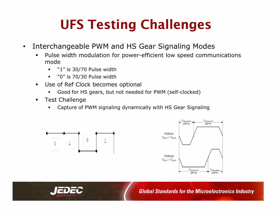
• Interchangeable PWM and HS Gear Signaling Modes� Pulse width modulation for power-efficient low speed communications
mode
� “1” is 30/70 Pulse width
� “0” is 70/30 Pulse width
� Use of Ref Clock becomes optional
� Good for HS gears, but not needed for PWM (self-clocked)
� Test Challenge
� Capture of PWM signaling dynamically with HS Gear Signaling� Capture of PWM signaling dynamically with HS Gear Signaling

UFS Testing Challenges UFS Testing Challenges Dynamic Signaling & Operation
• Multiple power modes
• STALL/SLEEP: power saving states; mandatory
• HIBERN8: enables ultra low power consumption
• DISABLED: a Powered state where module operation is disabled by RESET
• UNPOWERED: Power supply is withdrawn
• Dynamic nature makes protocol “capture” difficult
• MPHY PWM & HS Gears challenging for FPGA-based signal decoding
• Dependent on oscilloscopes for protocol decoding
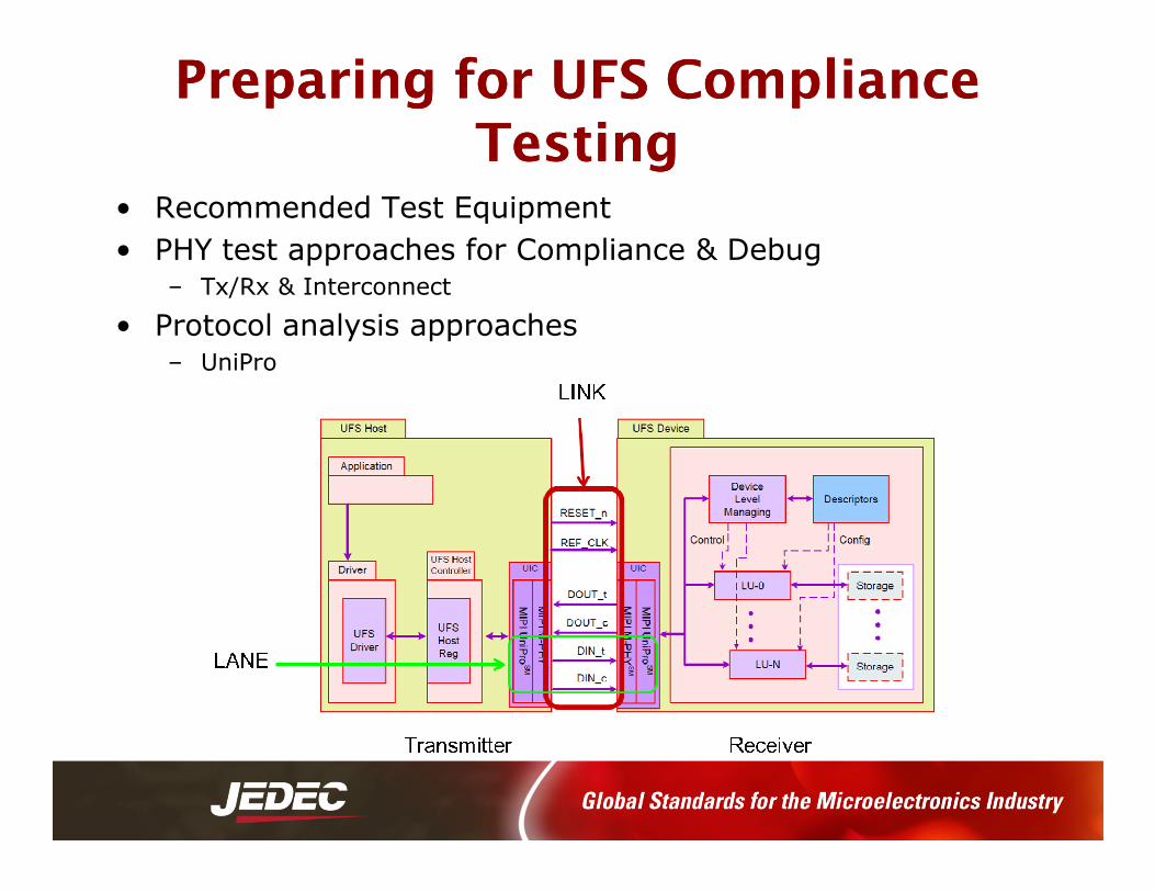
Preparing for UFS Compliance Preparing for UFS Compliance TestingTesting
• Recommended Test Equipment
• PHY test approaches for Compliance & Debug– Tx/Rx & Interconnect
• Protocol analysis approaches– UniPro

Preparing For UFS Electrical Preparing For UFS Electrical ComplianceCompliance
• Transmitter Testing– Oscilloscope for capture & verification of PWM and HS Gear Signaling
• Dynamic acquisition state
• Multiple channels (control/decoded protocol, HS gears, PWM gears)
• Signal Access– Probing
• Differential SMA-based
High Speed (HS)Gears A (Gbps) B (Gbps)
OscilloscopeBandwidth
G1 1.25 1.45 6 GHz
G2 2.5 2.91 8 GHz
G3 5 5.83 20 GHz
PWM (ie. TYPE-I)
Gears Min (Mb/s) Max (Mb/s)
G0 0.01 3 50 MHz
G1 3 9 50 MHz
G2 6 18 100 MHz
G3 12 36 150 Mhz
G4 24 72 250 MHz
G5 48 144 500 MHz
G6 96 288 1 GHz
G7 192 576 4 GHz
SYS (ie. TYPE-II) 576 (Mb/s) 4 GHz
Preparing For UFS Electrical Compliance
MM--PHY PHY TriggeringTriggering
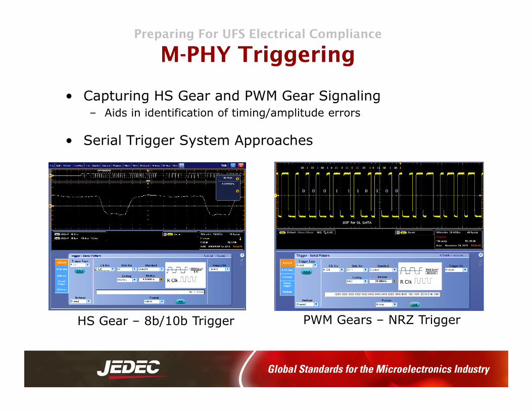
• Capturing HS Gear and PWM Gear Signaling– Aids in identification of timing/amplitude errors
• Serial Trigger System Approaches
PWM Gears – NRZ TriggerHS Gear – 8b/10b Trigger

Preparing For UFS Electrical Compliance
MM--PHY PHY HS Gear Decode, Trigger & SearchHS Gear Decode, Trigger & Search
• Aids debugging by verifying consistency of bus performance over time
• Decode function can look Symbols or 10-bit Characters
• Decode HS Gear 1 - 3 Data Rates
• Trigger & Search on– Any Control Character
– Character/ Symbol
– Pattern– Pattern
– Error (Character Error & Disparity Error)

Preparing For UFS Electrical Compliance
MM--PHY PHY TxTx Test AutomationTest Automation• Tests today are tied to M-PHY CTS Specification 1.0
– CTS1.0 just released by MIPI
14

Preparing for UFS Interconnect Preparing for UFS Interconnect ComplianceCompliance
• Board and PHY impedance tests that address tolerance for PHY insertion loss on M-PHY devices
• Requires time and frequency domain analysis– Time domain tests
• Impedance
• Delay
– Frequency domain tests
• Differential insertion loss• Differential insertion loss
• Sampling Oscilloscope w/S Parameter Capability
UFS Interconnect Testing
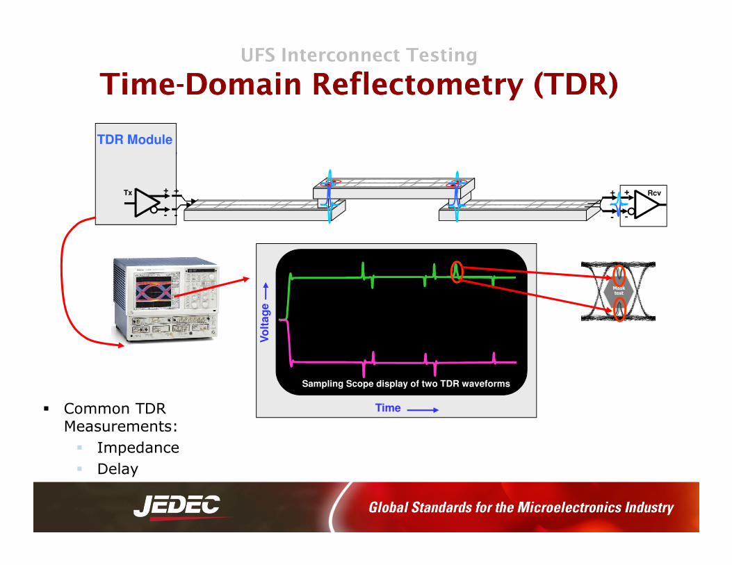
TimeTime--Domain Domain ReflectometryReflectometry (TDR)(TDR)
+
-
+
-
Rcv
TDR Module
+
-
+
-
Tx
Time
Vo
lta
ge
Sampling Scope display of two TDR waveforms
Mask
test
� Common TDR Measurements:
� Impedance
� Delay

UFS Interconnect TestingUFS Interconnect Testing
Frequency Domain Frequency Domain SS--ParametersParameters
• Frequency-domain characterization of reflections and loss on UFS Interconnects
� Common S-parameter Measurements: � Differential return loss� Differential return loss� Differential insertion loss� Frequency domain crosstalk
UFS Interconnect Testing
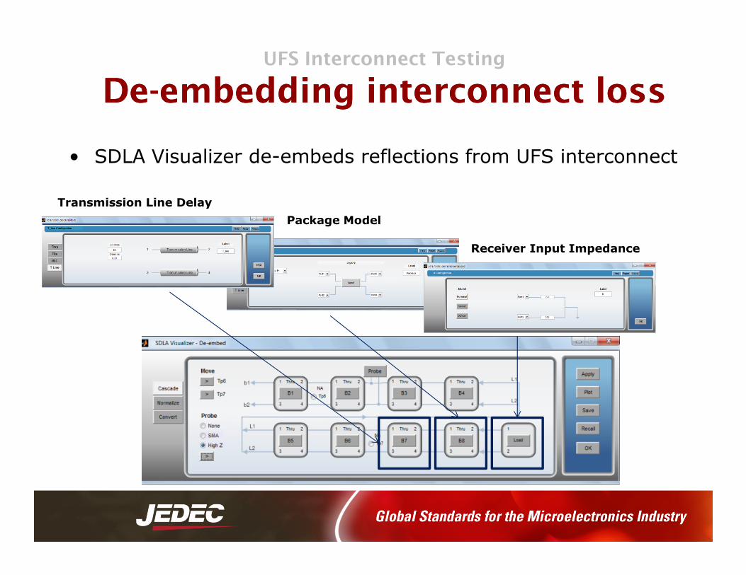
DeDe--embedding interconnect lossembedding interconnect loss
• SDLA Visualizer de-embeds reflections from UFS interconnect
Receiver Input Impedance
Package Model
Transmission Line Delay

Preparing for UFS Electrical Preparing for UFS Electrical ComplianceCompliance
• M-PHY Receiver Testing (needed for HS Gears)– Stimulus
• Arbitrary Waveform Generator
– Bit Error Detector• Oscilloscope

MM--PHY Rx TestingPHY Rx TestingGenerating Test Impairments using Arbitrary Waveform GeneratorGenerating Test Impairments using Arbitrary Waveform Generator
• Support needed for flexible signal impairments for characterization.
• Support needed for Jitter insertion and Pulse Width Modulation as per the M-PHY CTS v1.0.
• Support for DUT in both loopback and non-loopback mode.
1M 10M 41.7M
Compliance Test points
0.5UI
SJ Frequency [Hz]
TJ [U
I]

MM--PHY Rx Test AutomationPHY Rx Test AutomationOscilloscopeOscilloscope--based Mbased M--PHY BER with AWG as Pattern SourcePHY BER with AWG as Pattern Source
• HS Gear 8b/10b Error Detect & Pattern Generation:
– Hardware Serial trigger: 1.25 Gb/s -6.25 Gb/s
– BER for PRBS @ 312Mbs+ data rates.
• Testing Guidance in published Tek Methods of Implementation

Preparing For UFS Protocol TestingPreparing For UFS Protocol Testing
• Protocol Analysis of UFS– Oscilloscope for capture & decoding of UniPro and UFS protocol
• Consistent with MPHY Bandwidth recommendations
– Ensure link traffic edge captures
– UniPro defines a universal chip-to-chip data transport protocol, providing a common tunnel for higher-level protocols

UFS Protocol Testing
Seamless PHY & Protocol ViewsSeamless PHY & Protocol Views
• Protocol Decode placed right below oscilloscope waveforms
• Packet level info collapses to view packet content
• Link the UniPro/UFS packet to oscilloscope waveform

• Enable faster system level protocol debugging– Trigger – target specific
events/messages
– Protocol and physical layer data correlation
• Speed up verification for UFS Compliance
UFS Protocol Testing
Speed Speed up verification & compliance checksup verification & compliance checks
Compliance– Automated CRC computation to
monitor CRC errors in protocol packet
• Conforms to UniPro Protocol Specification version 1.41.00
Looking AheadLooking Ahead
• UFS Compliance Testing
–An open test house / certification process
–A multi-vendor CTS specification
–Vendor-based “Methods of Implementation”
• MIPI Alliance
–UFS2.0 support is well-defined with UniPro v.1.6 & MPHY 3.0 but future requirements for UFS3.0 have just begun
• UniPro WG seeking more formal requirements discussions for future of UFS3.0

Tektronix MTektronix M--PHY & Memory Testing PHY & Memory Testing ResourcesResources
• Videos/Webinars
• Application Notes
• Product Manuals
• Product Data Sheets
• Recommended Test Equipment
• M-PHY CTS Test Spec
www.tek.com/technology/ddr
www.tek.com/technology/mipi