uds1.2m sp 3 - brasilsat description the udx antenna´s family are the ultra high performance...
TRANSCRIPT

Installation Instructions
UDS Antenna´s Family With 120 cm Diameter

DESCRIPTION
The UDX antenna´s family are the Ultra High Performance antennas, operating in single polarization,
provided by Brasilsat Harald S/A. The antennas are designed for short-haul microwave systems in all
common frequency ranges from 7 GHz to 23 GHz. They are typically deployed in dense urban areas,
metropolitan and suburban locations, aggregation points. They are especially optimized to integrated
radios to reduce costs, installation complexity and time.
This Installation Instruction is valid for antennas in the following version:
• Antenna models: UDS71-12S; UDS107-12S; UDS144-12S; UDS177-12S and UDS212-12S
• Reflector Ø 120 cm;
• Dual polarization;
• Standard mount for support pipe Ø 114 mm;
• Reflector aperture covered by a radome;
• The design allows a fine adjustment range of +-10° for elevation and +-15° for azimuth;
NOTE
� This instruction must be read completely before sta rting the installation. � The installation/maintenance/removal need to be mad e by qualified personnel. � Brasilsat Harald S/A disclaims any responsibility f or the result of improper and unsafe
installation. � The pole/tower/other structural element involved to support the complete antenna as
described in this instruction must be verified/appr oved by structural specialist in respect to all the national/local regulation.
� All the required tools/instruments must be availabl e. � It is important to mount the antennas exactly as de scribed in this document. Don’t use
any parts, screws/nuts, not included in the packagi ng or not recommended by the supplier.
� The Antenna system should be inspected once a year by qualified and experienced personnel to verify proper installation/maintenance /condition of equipments.

II
INDEX
1 List of the mounting tools....................................................... 4
1.1 List of the mounting tools............................................................. 4
2 Antenna installation ............................................................. 4
2.1 List of the parts ..................................................................... 4
2.2 Installation Steps.................................................................... 6
2.2.1 Install Shroud ..................................................................... 6
2.2.2 Install Top Ring ................................................................... 7
2.2.3 In stalling Feed assembiy........................................................... 8
2.2.4 Installing Mounting assembly........................................................ 9
2.2.5 Install Anti-slip assembly ........................................................... 9
2.2.6 Lift the antenna to a tower ......................................................... 10
2.2.7 Install the antenna to the mounting pole ............................................. 10
2.2.8 Install articulated bolt assembly .................................................... 11
2.2.9 Adjust antenna azimuth ........................................................... 12
2.2.10 Adjust antenna elevation ......................................................... 13
2.2.11 Install Azimuth Strut assembly .................................................... 14
3 Mechanical Torque ............................................................ 15
4 Final check...................................................................... 15

- 4 -
1 List of the mounting tools
1.1 List of the mounting tools
The installation tools are listed in Table 1.
Table 1 - List of the mounting tools
NO. Name Specification Quantity
1 Crowbar 1 pcs
2 Spanner S=8,13, 18, 21, 24 2 pcs
3 Screwdriver for cross-recessed head screws 1 pcs
4 Diagonal pliers 1 pcs
2 Antenna installation
2.1 List of the parts
Please kindly check all the parts in Accessories Box according to Table 2 below
Table 2 - Packing List of Shipping Box
1.Reflector assembly (1 set)
2. Radome(1pcs)
3. Azimuth strut assembly (1 set)
4. Pre-assembly mount kit (1 set)
5. Shroud assembly (4sets)
6. Accessories Box (1 pcs)
(Check the List in Table 3)

- 5 -
Please kindly check all the parts in Accessories Box according to Table 3 below:
Table 1 Table 3 : Packing List of Accessories Box
1. Mechanical Flange (1 pcs)
2. Anti-slip assembly (1 set)
3. Side strut assembly (1 set)
4. U-bolt assembly (2 sets)
5. M6*20 Screw assembly ( 24 sets for use, 1 set for spare)
6. Eye-Bolt assembly (1 set)
7. Feed assembly (1 set)
8. M4*10 Allen screw (3 pcs) 9. M6*25 Allen screw (6 pcs)
10. Allen Key S=5 (1 pcs) 11. Allen Key S=3 (1 pcs) 12. Lubricant (1 bottle)
A Bag of documents: 13. Specification Instruction (1 copy) 14. Installation Manual (1 copy)

- 6 -
2.2 Installation Steps
2.2.1 Install Shroud
There are red marks (“B”, “L”, “R”, “TOP” ) on shrouds. Also there are red marks (“B”, “L”, “R”, “TOP” ) on the reflector. Install the shroud B into the position B of the reflector, and then load bolt
M5*16 2 flat washers, a spring washer and nut. Install the other shrouds in turn of “L”, “R”, “TOP”. Don’t fasten all the nuts and bolts now. You can get more details about the installation in the figure 1-3
below.
Figure 1: Install the shroud piece B
Figure 2:Install the shroud “L”,”R”
Same mark The direction of the shroud
Shroud “L” Shroud “R” Nut
Spring washer
Bolt M5*16
Flat Washer

- 7 -
Figure 3: Install the shroud marked “TOP”
2.2.2 Install Top Ring
Attention: When nuts, Flat washers, Spring washers, and anythi ng else drop into the
reflector during the installation, you must take th em out before installing the radome.
Figure 4: Fixing Ring
Shroud “TOP” This hole is used for the
next assembly(4 holes)
Nut, Spring washer, Bolt M5*16,Double flat washers Radome

- 8 -
2.2.3 In stalling Feed assembiy
Polarization
Vertical Polarization Horizontal Polarization Align the mark hole to “V” mark Align the mark hole to “H” mark
Figure 5: Polarization
Feed assembly
M4*10 Allen Screws
Align the mark hole to “V” mark
Remove the screws, change the polarization and then load and fasten them.
Polarization marker(red)
- 9 -
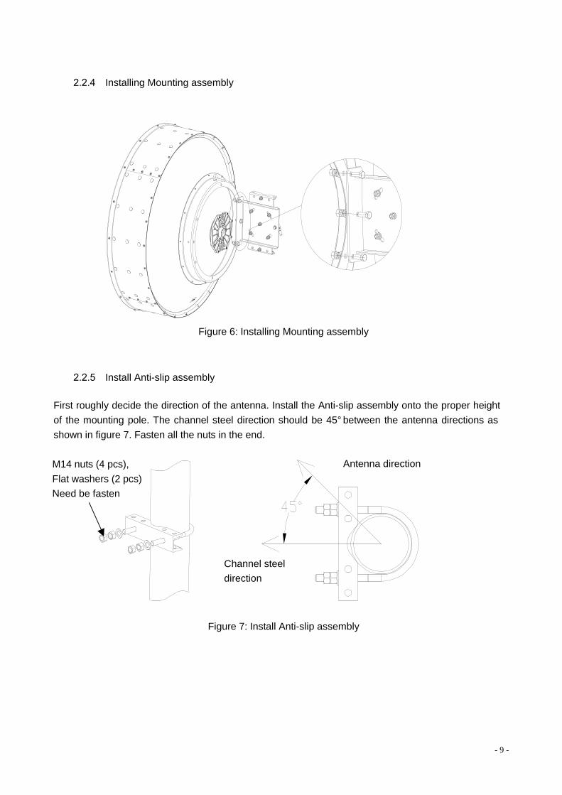
2.2.4 Installing Mounting assembly
Figure 6: Installing Mounting assembly
2.2.5 Install Anti-slip assembly
First roughly decide the direction of the antenna. Install the Anti-slip assembly onto the proper height
of the mounting pole. The channel steel direction should be 45° between the antenna directions as
shown in figure 7. Fasten all the nuts in the end.
Figure 7: Install Anti-slip assembly
M14 nuts (4 pcs),
Flat washers (2 pcs)
Need be fasten
Antenna direction
Channel steel
direction

- 10 -
2.2.6 Lift the antenna to a tower
Lift the antenna to a tower with a rope through the lifting hole as shown in figure 8. In order to avoid the
antenna rotation, you need to tow the antenna with another rope as shown in figure 8.
`
`
Figure 8: Lift the antenna
Attention: To avoid falling and damage, please mak e sure the rope is tighten before lifting.
During the installation, please protect the antenna from hitting of other objects due to the wave of the antenna resulting from the wind or other cau ses.
2.2.7 Install the antenna to the mounting pole
Lift the antenna on the Anti-slip assembly of the mounting pole. Diameter ranges of pole for this
Mounting assembly: Φ115 mm. Install the antenna to the mounting pole with 2 U-bolts, 8 nuts (M14), 4
Flat washers. Mounting assembly must be clung to the Anti-slip assembly. Moreover, the channel steel
direction should be 45° between the antenna directi on as shown in figure 9. Don’t fasten all the nuts
now.
Rope Lifting hole
Rope towing antenna

- 11 -
Figure 9:Install antenna to the mounting pole
2.2.8 Install articulated bolt assembly
Install articulated bolt assembly onto the Anti-slip assembly and mounting assembly as shown in figure
10.
Figure 10: Install articulated bolt
U-bolt (2 pcs)
Eye-Bolt assembly

- 12 -
2.2.9 Adjust antenna azimuth
Loose the double nuts as shown in the figure 11-12 below to adjust antenna azimuth. The azimuth
range is ±15°.
Figure 11: Adjust antenna azimuth 1
Figure 12: Adjust antenna azimuth 2
Loose the double nuts(M16)here to
adjust the antenna azimuth

- 13 -
2.2.10 Adjust antenna elevation
Loose the nuts, bolts as shown in the figure below. After the installation, fasten them. Then loose the
nuts as shown in figure 13 to adjust antenna elevation. The range is ±10°, as shown in figure 13-14.
Adjust azimuth and elevation repeatedly until get the antenna to the proper position. Fasten mounting
assembly, U-bolt, bolts of Anti-slip assembly, articulated bolt assembly and all the other bolts and nuts.
Figure 13: Adjust antenna elevation 1
Figure 14: Adjust antenna elevation 2
Before installation, loose the 10 nuts and a bolt
(M12), bolts here. After the installation, fasten them
Loose the double nuts here to adjust antenna elevation.

- 14 -
2.2.11 Install Azimuth Strut assembly
Figure 15: Installing Side strut assembly
Figure 16: Install Azimuth Strut assembly
Attention: Installing the Azimuth Strut assembly, the angle limit is 25°in horizontal and
vertical direction as shown in figure 17. If the an gel is over the limit, please change the position of the side strut tower end clamp on the tower.
Figure 17: Side strut assembly mounting 3
Bolt M12*45, flat washers, nuts
Side strut assembly
Azimuth strut assembly

- 15 -
3 Mechanical Torque
Diameter of screw (mm) M5 M10 M12 M16
Value (N•m) 2.3 21.9 38.2 93.1
4 Final check When the installation of the antenna has been completed, it is necessary to make sure that the
installation instructions has been followed in all aspects. It is especially important to check that all
bolted joints are tightly locked.