typical system specifications description the af-900® series digital fsk track circuit provides...
TRANSCRIPT

General Description
The AF-900® Series Digital FSK Track Circuit provides unmatched capabilities for train detection and delivery of complex train control data to moving transit vehicles. This system is ideal for management of heavy mass transit traffic with close operating headways, and provides the high reliability for demanding driverless operation.
AF-900 Series Track Circuits are simpler to install, calibrate, and maintain than any other audio frequency systems. Its web interface allows for initial local configuration and troubleshooting from the maintenance shop. AF-900 Series Track Circuits are now successfully deployed on a variety of major transit properties around the world, such as the LA Metro Green Line, Copenhagen Metro, Shanghai Line 2 Metro, Pittsburgh PAAC, and Puerto Rico.
How It Works
The AF-900 Series Digital FSK Track Circuit can be part of an Automatic Train Control System (ATC), providing both train detection and transmission of digital cab signaling data for the Automatic Train Protection (ATP) function of the ATC. Track circuits served by this system include mainline, station areas, turnouts, crossovers, storage yards, and highway crossing zones.
In AF-902 Track Circuit applications, the system typically uses two redundant subsystems to control two track circuits. This configuration is primarily used in driverless applications where high availability is key.
In AF-904 Track Circuit applications, the system typically uses four non-redundant subsystems to control up to four track circuits.
AF-900 Series Track Circuits are managed by Ansaldo STS USA MicroLok®II units. The MicroLok II units generate vital messages (train speed/direction, next carrier transmit frequency, track circuit ID, etc.) to the vehicle cab signal system. Train detection indications can be sent via Ethernet communications link or dedicated vital outputs. No track relay is needed for the detection functions.
Signals and messages in the rails are communicated to and from the AF-900 Series via simple but highly effective Track Cable Bonds, consisting of heavy (e.g. 350 or 500 MCM) cable connected between the rails in “S”, “O”, or “I” arrangement as required by the location.
Insulated rail joints are not required at mainline, crossover, or station locations, simple or universal crossovers. In a diamond crossover, a power frequency track circuit is used for train and broken rail detection.
TYPICAL SYSTEM SPECIFICATIONS
TYPICAL TRACK LAYOUT
CONTACT INFORMATIONContact your account representative for information on how to order our AF-900 Series Digital FSK Track Circuits Generation ll.
Typical System SpecificationsCarrier Frequency 9.5, 10.5, 11.5, 12.5, 13.5, 14.5,15.5,15.5,16.5 kHz
Modulation: Binary Frequency Shift Keyed carrier
Baud Rate:Shift:
200 BPS +200 Hz
Bandwidth: T.C. Length:
500 Hz 1000 ft. (max.), 65 ft. (min.)
Shunt Sensitivity: <0.25 ohms ballast
Pre/Post Shunt: <5.0 ft.
Cab Sig. Message: 37 data, 8 header, 12 CRC bits
Security: 2 messages, CRC cont. reception
Speed Commands: 32 speed defined per property
Blocking Speeds: a subset of the speed command
Track Circuit ID No.: 0 to 4095
Communication to Vital Controller: Peer
Communication: HTTP, SNMP, SLP
www.ansaldo-sts.com
AF-900® SERIES DIGITAL FSK TRACK CIRCUITSGENERATION II
Ansaldo STS USA, Inc.
1000 Technology DrivePittsburgh, PA 15219-3120 USAtel + 1.800.351.1520fax + 1.412.688.2399email: [email protected]
© 2014 Ansaldo STS USA, Inc. Bulletin No. 839AF-900® and MicroLok® are registered trademarks of Ansaldo STS USA, Inc.
The AF-900 is equipped with an embedded web server allowing for personnel in the central office or the maintenance office to verify track circuit level or error codes.
Adjustment of parameters can be done by accessing the web server. Remote tampering of the setting is prevented by requiring a physical contact with the AF-900 track circuit controller in the technical room.
The AF-900 also includes embedded diagnostics, allowing for automatic reporting of faulty conditions. In case a default or a malfunction is detected, an error code is sent to a central location using Internet standard SNMP protocol. Synopses such as the one below can be built for simple reporting of the health of your system, integrating in one view train control and IT infrastructure.
More details of each track circuit, such as history, revision management, documentation, etc., are available depending on the Network Management System chosen.
Basic System Operation
Each AF-900 Series system vitally monitors the status of one track circuit. An FM audio frequency carrier is
transmitted at one end of the track circuit and received at the other. This carrier is modulated in a binary manner to generate digital cab signal data for the train. Carrier level and a part of the digital message is monitored by the receiver to determine track occupancy.
Train Detection
Train detection is accomplished in the AF-900 Series System by measuring the amplitude of the digital track signal.
While the track circuit is unoccupied, the receiving AF-900 Series circuits continually check the incoming message for proper signal threshold and accuracy. If a message is received, but fails accuracy checks, the AF-900 Series unit notifies the MicroLok II system of the presence of a train.
When a train shunts the rails, this condition is recognized by the receiving AF-900 Series track circuits as a drop below a preset signal threshold, and is reported to the associated MicroLok II system. When the train clears a track circuit, the received signal threshold is restored; the AF-900 Series system responds accordingly.
Since the AF-900 Series Track Circuit continually monitors the signal carried in the rails, it also provides broken rail detection.
Cab Signal Data Transmission
One of the major strengths of the AF-900 Series Track Circuit is its extensive cab signal data transmission apability, made possible through Binary Frequency Shift Keying (BFSK) modulation. A typical set of cab signal data elements includes:
For example, line and target speed commands could range from 0 to 65 mph in 5 mph steps, plus additional speeds of 8 mph and 1 mph. Isolation of commands
Name Function
Line Speed Maximum speed permitted within track circuit target application
Target Speed Desired speed at track circuit target
Distance-to-Go Distance to target speed
Next Frequency Carrier frequency of the next track circuit
Track Circuit ID Identification of present track circuit
Berthed (Door Open) OK to open vehicle doors at station
Current Direction Train direction of travel (E or W, N or S)
Change Direction Reverse train direction of travel
Couple/Uncouple Couple/uncouple cars during train consist make-up
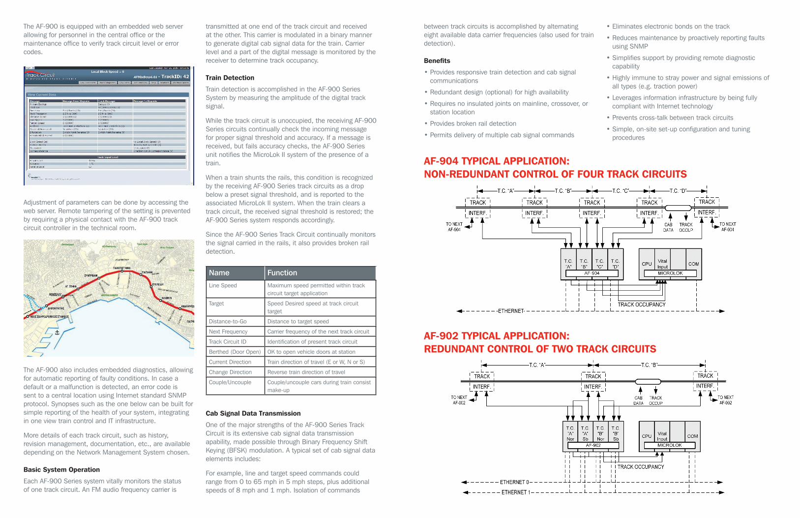
AF-904 TYPICAL APPLICATION: NON-REDUNDANT CONTROL OF FOUR TRACK CIRCUITS
AF-902 TYPICAL APPLICATION: REDUNDANT CONTROL OF TWO TRACK CIRCUITS
between track circuits is accomplished by alternating eight available data carrier frequencies (also used for train detection).
Benefits
• Provides responsive train detection and cab signal communications
• Redundant design (optional) for high availability
• Requires no insulated joints on mainline, crossover, or station location
• Provides broken rail detection
• Permits delivery of multiple cab signal commands
• Eliminates electronic bonds on the track
• Reduces maintenance by proactively reporting faults using SNMP
• Simplifies support by providing remote diagnostic capability
• Highly immune to stray power and signal emissions of all types (e.g. traction power)
• Leverages information infrastructure by being fully compliant with Internet technology
• Prevents cross-talk between track circuits
• Simple, on-site set-up configuration and tuning procedures