types and causes of concrete deterioration
TRANSCRIPT

Corrosion of reinforcing steel and other embedded metals is theleading cause of deterioration in concrete. When steel corrodes, theresulting rust occupies a greater volume than the steel. This expan-sion creates tensile stresses in the concrete, which can eventuallycause cracking, delamination, and spalling (Figs. 1 and 2).
Steel corrodes because it is not a naturally occurring material.Rather, iron ore is smelted and refined to produce steel. Theproduction steps that transform iron ore into steel add energyto the metal.
Steel, like most metals except gold and platinum, is thermody-namically unstable under normal atmospheric conditions andwill release energy and revert back to its natural state—ironoxide, or rust. Thisprocess is calledcorrosion.
For corrosion to occur,four elements must bepresent: There must beat least two metals (ortwo locations on asingle metal) at dif-ferent energy levels,an electrolyte, and ametallic connection. In
reinforced concrete,the rebar may havemany separate areasat different energylevels. Concrete actsas the electrolyte,and the metallicconnection is pro-vided by wire ties,chair supports, orthe rebar itself.
Corrosion is an electrochemical process involving the flow ofcharges (electronsand ions). Fig. 3shows a corrodingsteel bar embeddedin concrete. Atactive sites on thebar, called anodes,iron atoms loseelectrons and moveinto the surround-ing concrete asferrous ions. Thisprocess is called a
Types and Causes of Concrete DeteriorationAbrasion /Erosion . . . . . . . . . . . . . . . . . . . . . . . . . . . . . . . . . . . . . 9
Traffic surfaces . . . . . . . . . . . . . . . . . . . . . . . . . . . . . . . . . . . . . 9Hydraulic structures. . . . . . . . . . . . . . . . . . . . . . . . . . . . . . . . . 10
Fire/Heat . . . . . . . . . . . . . . . . . . . . . . . . . . . . . . . . . . . . . . . . . . 10Restraint to Volume Changes . . . . . . . . . . . . . . . . . . . . . . . . . . . 12
Plastic shrinkage cracking . . . . . . . . . . . . . . . . . . . . . . . . . . . . 12Drying shrinkage cracking . . . . . . . . . . . . . . . . . . . . . . . . . . . . 12Thermal stresses . . . . . . . . . . . . . . . . . . . . . . . . . . . . . . . . . . . 12
Overload and Impact . . . . . . . . . . . . . . . . . . . . . . . . . . . . . . . . . 12Loss of Support. . . . . . . . . . . . . . . . . . . . . . . . . . . . . . . . . . . . . . 13Surface Defects . . . . . . . . . . . . . . . . . . . . . . . . . . . . . . . . . . . . . 13
Formed surfaces . . . . . . . . . . . . . . . . . . . . . . . . . . . . . . . . . . . 13Finished surfaces . . . . . . . . . . . . . . . . . . . . . . . . . . . . . . . . . . . 14
References . . . . . . . . . . . . . . . . . . . . . . . . . . . . . . . . . . . . . . . . . 15
IS536
The exceptional durability of portland cement concrete is a major reason why it is the world’s most widely used construction material.But material limitations, design and construction practices, and severe exposure conditions can cause concrete to deteriorate, whichmay result in aesthetic, functional, or structural problems.
Concrete can deteriorate for a variety of reasons, and concrete damage is often the result of a combination of factors. The followingsummary discusses potential causes of concrete deterioration and the factors that influence them.
CORROSION OF EMBEDDED METALS
Fig. 1. Corrosion of reinforcing steel isthe most common cause of concretedeterioration. (46080)
Steel Corrosionby-products(rust)
Fig. 2. The expansion of corroding steelcreates tensile stresses in the concrete,which can cause cracking,delamination, and spalling.
4e-
4e-
4OH-
2Fe+
2Fe(OH)2
2H2O
2H2O
O2 O2
Fe2O3•H2O
Secondary
AnodeCathode
Fig. 3. When reinforcing steel corrodes,electrons flow through the bar and ionsflow through the concrete.
Corrosion of Embedded Metals . . . . . . . . . . . . . . . . . . . . . . . . . . 1Concrete and the passivating layer . . . . . . . . . . . . . . . . . . . . . . . 3 The role of chloride ions . . . . . . . . . . . . . . . . . . . . . . . . . . . . . . 3Carbonation . . . . . . . . . . . . . . . . . . . . . . . . . . . . . . . . . . . . . . . 3Dissimilar metal corrosion . . . . . . . . . . . . . . . . . . . . . . . . . . . . . 4
Freeze-Thaw Deterioration . . . . . . . . . . . . . . . . . . . . . . . . . . . . . 4Deicer scaling . . . . . . . . . . . . . . . . . . . . . . . . . . . . . . . . . . . . . . 4Aggregate expansion . . . . . . . . . . . . . . . . . . . . . . . . . . . . . . . . . 5
Chemical Attack . . . . . . . . . . . . . . . . . . . . . . . . . . . . . . . . . . . . . 5Acids . . . . . . . . . . . . . . . . . . . . . . . . . . . . . . . . . . . . . . . . . . . . 5Salts and alkalis. . . . . . . . . . . . . . . . . . . . . . . . . . . . . . . . . . . . . 6Sulfate attack. . . . . . . . . . . . . . . . . . . . . . . . . . . . . . . . . . . . . . . 7
Alkali-Aggregate Reactivity . . . . . . . . . . . . . . . . . . . . . . . . . . . . . 8Alkali-silica reactivity. . . . . . . . . . . . . . . . . . . . . . . . . . . . . . . . . 9Alkali-carbonate reactivity . . . . . . . . . . . . . . . . . . . . . . . . . . . . . 9

half-cell oxidation reaction, or the anodic reaction, and isrepresented as:
2Fe → 2Fe2+ + 4e-
The electrons remain in the bar and flow to sites called cathodes,where they combine with water and oxygen in the concrete. Thereaction at the cathode is called a reduction reaction. A commonreduction reaction is:
2H2O + O2 + 4e- → 4OH-
To maintain electrical neutrality, the ferrous ions migrate throughthe concrete pore water to these cathodic sites where theycombine to form iron hydroxides, or rust:
2Fe2+ + 4OH- → 2Fe(OH)2
This initial precipitated hydroxide tends to react further withoxygen to form higher oxides. The increases in volume as thereaction products react further with dissolved oxygen leads tointernal stress within the concrete that may be sufficient to causecracking and spalling of the concrete cover.
Corrosion of embedded metals in concrete can be greatly re-duced by placing crack-free concrete with low permeability andsufficient concrete cover. Table 1 shows the concrete cover re-quirements for different exposure conditions as set by ACI 318,Building Code Requirements for Structural Concrete.
2
Portland Cement Association
Table 1. Minimum Concrete Cover Requirements (ACI 318)
Cast-In-Place Concrete Min. cover, mm (in.)Concrete cast against and permanently exposed to earth 75 (3)Concrete exposed to earth or weather:
No. 19 (No. 6) through No. 57 (No. 18) bars 50 (2)No. 16 (No. 5) bar, MW200 (W31) or
MD200 (D31) wire, and smaller 40 (11⁄2)Concrete not exposed to weather or in contact with ground:
Slabs, Walls, Joists:No. 43 (No. 14) and No. 57 (No. 18) bars 40 (11⁄2)No. 36 (No. 11) bar and smaller 20 (3⁄4)
Beams, columns:Primary reinforcement, ties, stirrups, spirals 40 (11⁄2)
Shells, folded plate members:No. 19 (No. 6) bar and larger 20 (3⁄4)No. 16 (No. 5) bar, MW200 (W31) or
MD200 (D31) wire, and smaller 15 (1⁄2)Precast Concrete1
Concrete exposed to earth or weather:Wall panels:
No. 43 (No. 14) and No. 57 (No. 18) bars 40 (11⁄2)No. 36 (No. 11) bar and smaller 20 (3⁄4)
Other members:No. 43 (No. 14) and No. 57 (No. 18) bars 50 (2)No. 19 (No. 6) through No. 36 (No. 11) bars 40 (11⁄2)No. 16 (No. 5), MW200 (W31) or 30 (11⁄4)
MD200 (D31) wire, and smallerConcrete not exposed to weather or in contact with ground:
Slabs, walls, joists:No. 43 (No. 14) and No. 57 (No. 18) bars 30 (11⁄4)No. 36 (No. 11) bar and smaller 15 (5⁄8)
Beams, columns:Primary reinforcement db but not less than 15 (5⁄8) and need not exceed 40 (11⁄2)Ties, stirrups, spirals 10 (3⁄8)
Shells, folded plate members:No. 19 (No. 6) bar and larger 15 (5⁄8)No. 16 (No. 5) bar, MW200 (W31) or 10 (3⁄8)
MD200 (D31) wire, and smallerPrestressed Concrete2
Concrete cast against and permanently exposed to earth 75 (3)Concrete exposed to earth or weather:
Wall panels, slabs, joists 25 (1)Other members 40 (11⁄2)
Concrete not exposed to weather or in contact with ground:Slabs, walls, joists 20 (3⁄4)Beams, columns:
Primary reinforcement 40 (11⁄2)Ties, stirrups, spirals 25 (1)
Shells, folded plate members:No. 16 (No. 5) bar, MW200 (W31) or 10 (3⁄8)
MD200 (D31) wire, and smallerOther reinforcement db but not less than 20 (3⁄4)
1Manufactured under plant controlled conditions. 2Modification to the cover requirements are possible depending on the manufacturing method andtensile stress in the member. See ACI 318.db = diameter of reinforcing bar
Concrete and the Passivating LayerAlthough steel’s natural tendency is to undergo corrosionreactions, the alkaline environment of concrete (pH of 12 to 13)provides steel with corrosion protection. At the high pH, a thinoxide layer forms on the steel and prevents metal atoms from dis-solving. This passive film does not actually stop corrosion; itreduces the corrosion rate to an insignificant level. For steel inconcrete, the passive corrosion rate is typically 0.1 µm per year.Without the passive film, the steel would corrode at rates at least1,000 times higher (ACI 222 2001).
Because of concrete’s inherent protection, reinforcing steel doesnot corrode in the majority of concrete elements and structures.However, corrosion can occur when the passivating layer isdestroyed. The destruction of the passivating layer occurs whenthe alkalinity of the concrete is reduced or when the chlorideconcentration in concrete is increased to a certain level.
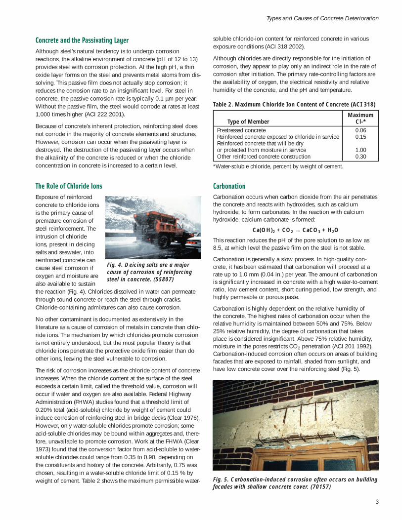
The Role of Chloride IonsExposure of reinforcedconcrete to chloride ionsis the primary cause ofpremature corrosion ofsteel reinforcement. Theintrusion of chlorideions, present in deicingsalts and seawater, intoreinforced concrete cancause steel corrosion ifoxygen and moisture arealso available to sustainthe reaction (Fig. 4). Chlorides dissolved in water can permeatethrough sound concrete or reach the steel through cracks.Chloride-containing admixtures can also cause corrosion.
No other contaminant is documented as extensively in theliterature as a cause of corrosion of metals in concrete than chlo-ride ions. The mechanism by which chlorides promote corrosionis not entirely understood, but the most popular theory is thatchloride ions penetrate the protective oxide film easier than doother ions, leaving the steel vulnerable to corrosion.
The risk of corrosion increases as the chloride content of concreteincreases. When the chloride content at the surface of the steelexceeds a certain limit, called the threshold value, corrosion willoccur if water and oxygen are also available. Federal HighwayAdministration (FHWA) studies found that a threshold limit of0.20% total (acid-soluble) chloride by weight of cement couldinduce corrosion of reinforcing steel in bridge decks (Clear 1976).However, only water-soluble chlorides promote corrosion; someacid-soluble chlorides may be bound within aggregates and, there-fore, unavailable to promote corrosion. Work at the FHWA (Clear1973) found that the conversion factor from acid-soluble to water-soluble chlorides could range from 0.35 to 0.90, depending onthe constituents and history of the concrete. Arbitrarily, 0.75 waschosen, resulting in a water-soluble chloride limit of 0.15 % byweight of cement. Table 2 shows the maximum permissible water-
soluble chloride-ion content for reinforced concrete in variousexposure conditions (ACI 318 2002).
Although chlorides are directly responsible for the initiation ofcorrosion, they appear to play only an indirect role in the rate ofcorrosion after initiation. The primary rate-controlling factors arethe availability of oxygen, the electrical resistivity and relativehumidity of the concrete, and the pH and temperature.
3
Types and Causes of Concrete Deterioration
Fig. 4. Deicing salts are a majorcause of corrosion of reinforcingsteel in concrete. (55807)
Table 2. Maximum Chloride Ion Content of Concrete (ACI 318)
MaximumType of Member Cl-*
Prestressed concrete 0.06Reinforced concrete exposed to chloride in service 0.15Reinforced concrete that will be dry or protected from moisture in service 1.00Other reinforced concrete construction 0.30
*Water-soluble chloride, percent by weight of cement.
CarbonationCarbonation occurs when carbon dioxide from the air penetratesthe concrete and reacts with hydroxides, such as calciumhydroxide, to form carbonates. In the reaction with calciumhydroxide, calcium carbonate is formed:
Ca(OH)2 + CO2 → CaCO3 + H2O
This reaction reduces the pH of the pore solution to as low as8.5, at which level the passive film on the steel is not stable.
Carbonation is generally a slow process. In high-quality con-crete, it has been estimated that carbonation will proceed at arate up to 1.0 mm (0.04 in.) per year. The amount of carbonationis significantly increased in concrete with a high water-to-cementratio, low cement content, short curing period, low strength, andhighly permeable or porous paste.
Carbonation is highly dependent on the relative humidity ofthe concrete. The highest rates of carbonation occur when therelative humidity is maintained between 50% and 75%. Below25% relative humidity, the degree of carbonation that takesplace is considered insignificant. Above 75% relative humidity,moisture in the pores restricts CO2 penetration (ACI 201 1992).Carbonation-induced corrosion often occurs on areas of buildingfacades that are exposed to rainfall, shaded from sunlight, andhave low concrete cover over the reinforcing steel (Fig. 5).
Fig. 5. Carbonation-induced corrosion often occurs on buildingfacades with shallow concrete cover. (70157)

Carbonation of concrete also lowers the amount of chloride ionsneeded to promote corrosion. In new concrete with a pH of 12to 13, about 7,000 to 8,000 ppm of chlorides are required tostart corrosion of embedded steel. If, however, the pH is loweredto a range of 10 to 11, the chloride threshold for corrosion issignificantly lower—at or below 100 ppm (Montani 1995). Likechloride ions, however, carbonation destroys the passive film ofthe reinforcement, but does not influence the rate of corrosion.
Dissimilar Metal CorrosionWhen two different metals, such as aluminum and steel, are incontact within concrete, corrosion can occur because each metalhas a unique electrochemical potential. A familiar type of dissim-ilar metal corrosion occurs in an ordinary flashlight battery. Thezinc case and carbon rod are the two metals, and the moist pasteacts as the electrolyte. When the carbon and zinc are connectedby a wire, current flows. In reinforced concrete, dissimilar metalcorrosion can occur in balconies where embedded aluminumrailings are in contact with the reinforcing steel.
Below is a list of metals in order of electrochemical activity:1. Zinc 7. Lead2. Aluminum 8. Brass3. Steel 9. Copper4. Iron 10. Bronze5. Nickel 11. Stainless Steel6. Tin 12. Gold
When the metals are in contact in an active electrolyte, the lessactive metal (lower number) in the series corrodes.
FREEZE-THAW DETERIORATIONWhen water freezes, it expands about 9%. As the water in moistconcrete freezes, it produces pressure in the capillaries and poresof the concrete. If the pressure exceeds the tensile strength of theconcrete, the cavity will dilate and rupture. The accumulativeeffect of successive freeze-thaw cycles and disruption of pasteand aggregate can eventually cause significant expansion andcracking, scaling, and crumbling of the concrete (Fig. 6). Fig. 7shows the severity of freeze-thaw exposure typically encountered
in different areas of the United States. Local weather records canalso be referenced to more precisely determine the severity ofexposure.
The resistance of concrete to freezing and thawing in a moistcondition is significantly improved by the use of intentionallyentrained air. Entrained air voids act as empty chambers in thepaste for the freezing and migrating water to enter, thus relievingthe pressure in the capillaries and pores and preventing damageto the concrete. Concrete air content requirements for variousexposure conditions are shown in Table 3.
Concrete with low permeability is also better able resist thepenetration of water and, as a result, performs better whenexposed to freeze-thaw cycles. The permeability of concrete isdirectly related to its water-to-cement ratio—the lower the water-to-cement ratio, the lower the permeability of the concrete. Table4 shows the maximum water-to-cementitious materials ratio andminimum compressive strength required for different exposureconditions.
4
Portland Cement Association
Fig 6. Freeze-thaw cycles can cause scaling of concretesurfaces. (A5273)
Common
*Higher elevations receive greater frequency of exposure
Rare*
Occasional*
Fig. 7. The frequency of freeze-thaw exposure typically en-countered in different areas of the United States.
Table 3. Target Air Contents for Frost-Resistant Concrete (ACI 318)
Air Content, %2
Nominal Maximum Severe ModerateAggregate Size1, mm (in.) Exposure Exposure
9 (3⁄8) 7.5 613 (1⁄2) 7 5.519 (3⁄4) 6 525 (1) 6 4.5
37.5 (11⁄2) 5.5 4.5503 (2) 5 4753 (3) 4.5 3.5
1 See ASTM C 33 for tolerance on oversize for various nominalmaximum size designations.
2 Concrete should have an air content within –1 to +2 percent of thetarget value.
3 These air contents apply to total mix, as for the preceding aggregatesizes. When testing these concretes, however, aggregate larger than37.5 mm (11⁄2 in.) is removed by hand-picking or sieving, and air con-tent is determined on the minus 37.5 mm (11⁄2 in.) fraction of mix (tol-erance on air content as delivered applies to this value). Air contentof total mix is computed from value determined on the minus 37.5mm (11⁄2 in.) fraction.

5
Types and Causes of Concrete Deterioration
Table 4. Requirements for Special Exposure Conditions (ACI 318)
MinimumMaximum Compressive
Exposure Condition w/cm1 Strength2
Concrete intended to havelow permeability whenexposed to water 0.50 4000Concrete exposed to freezingand thawing in a moistcondition or to deicing chemicals 0.45 4500For corrosion protection ofreinforcement in concreteexposed to chlorides from deicingchemicals, salt, saltwater,brackish water, seawater, orspray from these sources 0.40 5000
1 Water-to-cementitious materials ratio, by weight, normal weightaggregate concrete.
2 Normal-weight and lightweight aggregate concrete.
Deicer Scaling Deicing chemicals used for snow and ice removal, such assodium chloride, can aggravate freeze-thaw deterioration. Theadditional problem caused by deicers is believed to be a buildupof osmotic and hydraulic pressures in excess of the normal hy-draulic pressures produced when water in concrete freezes. Inaddition, because salt absorbs moisture, it keeps the concretemore saturated, increasing the potential for freeze-thaw dete-rioration. However, properly designed and placed air-entrainedconcrete can withstand deicers for many years.
In the absence of freezing, sodium chloride has little to nochemical effect on concrete. Weak solutions of calcium chloridegenerally have little chemical effect on concrete, but studies haveshown that concentrated calcium chloride solutions can chem-ically attack concrete. Magnesium chloride deicers have comeunder recent criticism for aggravating scaling. One study foundthat magnesium chloride, magnesium acetate, magnesium nitrate,and calcium chloride are more damaging to concrete thansodium chloride (Cody, Cody, Spry, and Gan 1996). Deicerscontaining ammonium nitrate and ammonium sulfate should beprohibited because they rapidly attack and disintegrate concrete(See section on “Chemical Attack,” page 7).
Aggregate ExpansionSome aggregates may absorb so much water (to criticalsaturation) that they cannot accommodate the expansion andhydraulic pressure that occurs during the freezing of water. Theresult is expansion of the aggregate and possible disintegration ofthe concrete if enough of the offending particles are present. If aproblem particle is near the surface of the concrete, it can causea popout (Fig. 8).
D-cracking is a form of freeze-thaw deterioration that has beenobserved in some pavements after three or more years of service.Due to the natural accumulation of water in the base and sub-
Fig. 8. Some aggregates absorb water and, upon freezing,expand to produce a popout. (0113)
Freezing of Fresh ConcreteConcrete gains very little early strength at low temperatures.Freshly mixed concrete must be protected against freezinguntil the degree of saturation of the concrete has been suffi-ciently reduced by cement hydration (Fig. 9). The time atwhich this reduction is accomplished corresponds roughly tothe time required for the concrete to attain a compressivestrength of 3.5 MPa (500 psi). At normal temperatures andwater-to-cement ratios less than 0.60, this typically occurswithin the first 24 hours after placement. Significant ultimatestrength reductions, up to about 50%, can occur if concrete isfrozen within the first few hours after placement or before itattains a compressive strength of 3.5 MPa (500 psi). Concreteto be exposed to deicers should attain a strength of 28 MPa(4000 psi) prior to exposure to cycles of freezing and thawing.
Concrete that has been frozen just once at an early age canoften be restored to nearly normal strength by providing favor-able subsequent curing conditions. Such concrete, however,will not be as resistant to weathering or as watertight as con-crete that had not been frozen. The critical period after whichconcrete is not seriously damaged by one or two freezingcycles depends on the concrete ingredients and conditions ofmixing, placing, curing, and subsequent drying. For example,air-entrained concrete is less susceptible to damage by earlyfreezing than non-air-entrained concrete.
Fig. 9. Ice crystals often form in concrete that isfrozen before it hardens. The disruption of the pastematrix by freezing can cause reduced strength gainand increased porosity. (44047)

6
Portland Cement Association
Fig. 11. Bacteria in sewage systems can produce sulfuric acid,which aggressively attacks concrete. (70149)
In addition to individual organic and mineral acids which mayattack concrete, acid-containing or acid-producing substances,such as acidic industrial wastes, silage, fruit juices, and sourmilk, will also cause damage.
Animal wastes contain substances which may oxidize in air toform acids which attack concrete. The saponification reactionbetween animal fats and the hydration products of portlandcement consumes these hydration products, producing salts andalcohols, in a reaction analogous to that of acids.
Acid rain, which often has a pH of 4 to 4.5, can slightly etchconcrete, usually without affecting the performance of theexposed surface.
Any water that contains bicarbonate ion also contains freecarbon dioxide, a part of which can dissolve calcium carbonateunless saturation already exists. This part is called the “aggressivecarbon dioxide.” Water with aggressive carbon dioxide acts byacid reaction and can attack concrete and other portland cementproducts whether or not they are carbonated.
Calcium-absorptive acidic soil can attack concrete, especiallyporous concrete. Even slightly acidic solutions that are lime-deficient can attack concrete by dissolving calcium from thepaste, leaving behind a deteriorated paste consisting primarilyof silica gel.
To prevent deterioration from acid attack, portland cement con-crete generally must be protected from acidic environments withsurface protective treatments. Unlike limestone and dolomiticaggregates, siliceous aggregates are acid-resistant and are some-times specified to improve the chemical resistance of concrete,especially with the use of chemical-resistant cement. Properlycured concrete with reduced permeability experience a slightlylower rate of attack from acids.
Salts and AlkalisThe chlorides and nitrates of ammonium, magnesium, aluminum,and iron all cause concrete deterioration, with those of ammo-nium producing the most damage. Most ammonium salts aredestructive because, in the alkaline environment of concrete,they release ammonia gas and hydrogen ions. These are replacedby dissolving calcium hydroxide from the concrete. The result is
base of pavements, the aggregate may eventually become satu-rated. Then with freezing and thawing cycles, cracking of theconcrete starts in the saturated aggregate at the bottom of theslab and progresses upward until it reaches the wearing surface(Fig. 10). D-cracking usually starts near pavement joints.
Aggregate freeze-thaw problems can often be reduced by eitherselecting aggregates that perform better in freeze-thaw cycles or,where marginal aggregates must be used, reducing the maximumparticle size.
Fig. 10. D-cracking is a form of freeze-thaw deterioration thathas been observed in some pavements after three or moreyears of service. (70155)
CHEMICAL ATTACKConcrete performs well when exposed to various atmosphericconditions, water, soil, and many other chemical exposures.However, some chemical environments can deteriorate evenhigh-quality concrete. The deleterious effects of some commonchemicals on concrete are shown in the box on page 7.
Concrete is rarely, if ever, attacked by solid, dry chemicals. Toproduce significant attack on concrete, aggressive chemicalsmust be in solution and above some minimum concentration.
Acids In general, portland cement concrete does not have good resis-tance to acids. In fact, no hydraulic cement concrete, regardlessof its composition, will hold up for long if exposed to a solutionwith a pH of 3 or lower. However, some weak acids can betolerated, particularly if the exposure is occasional.
Acids react with the calcium hydroxide of the hydrated portlandcement. In most cases, the chemical reaction forms water-solublecalcium compounds, which are then leached away by aqueoussolutions (ACI 201 1992).
The products of combustion of many fuels contain sulfurousgases which combine with moisture to form sulfuric acid. Also,certain bacteria convert sewage into sulfuric acid. Sulfuric acid isparticularly aggressive to concrete because the calcium sulfateformed from the acid reaction will also deteriorate concrete viasulfate attack (Fig. 11).

a leaching action, much like acid attack. Strong alkalies (over 20percent) can also cause concrete disintegration (ACI 515 1979).
Environmental conditions have a great influence on sulfateattack. The attack is greater in concrete exposed to wet/drycycling (Fig. 12). When water evaporates, sulfates can ac-cumulate at the concrete surface, increasing in concentrationand their potential for causing deterioration.
Porous concrete is susceptible to weathering caused by saltcrystallization. Examples of salts known to cause weathering offield concrete include sodium carbonate and sodium sulfate (lab-oratory studies have also related saturated solutions of calciumchloride and other salts to concrete deterioration). Under dryingconditions, salt solutions can rise to the surface by capillaryaction and, as a result of surface evaporation, the solution phasebecomes supersaturated and salt crystallization occurs, some-times generating pressures large enough to cause cracking andscaling (Mehta 2000).
Thaumasite may form during sulfate attack in moist conditions attemperatures usually between 0°C and 10°C (32°F to 50°F) and itoccurs as a result of a reaction between calcium silicate hydrate,sulfate, calcium carbonate, and water. In concrete undergoingexcessive thaumasite formation, cracks can be filled with thau-masite and haloes of white thaumasite surround aggregates. Atthe concrete/soil interface, the surface concrete layer can be“mushy” with complete replacement of the cement paste bythaumasite.
Sulfate attack is a particular problem in arid areas, such as theNorthern Great Plains and parts of the Western United States.Seawater also contains sulfates but is not as severe an exposureas sulfates in groundwater.
Resistance to sulfates can best be achieved by using a low water-to-cement ratio and a cement with a limited amount of tricalciumaluminates. As outlined in ASTM C 150, Type II cement containsless than 8% C3A, and Type V cement contains less than 5%.Cements meeting the ASTM C 1157 requirements of Type MScement (moderate sulfate resistant) and Type HS cement (high sul-fate resistant) can also be used to provide sulfate resistance, aswell as moderate sulfate-resistant cements per ASTM C 595.
Studies have shown that some pozzolans and ground-granulatedblast-furnace slags increase the life expectancy of concrete ex-posed to sulfates. Good results have been obtained with fly ash
7
Types and Causes of Concrete Deterioration
Chemicals That Deteriorate ConcretePromote rapid deterioration of concrete:Aluminum ChlorideCalcium BisulfiteHydrochloric Acid (all concentrations)*Hydrofluoric Acid (all concentrations)Nitric Acid (all concentrations)Sulfuric Acid, 10-80 percent*Sulfurous Acid
Promote moderate deterioration of concrete:Aluminum Sulfate* Mustard Oil*Ammonium Bisulfate Perchloric Acid, 10%Ammonium Nitrate Potassium DichromateAmmonium Sulfate* Potassium Hydroxide (>25%)Ammonium Sulfide Rapeseed Oil*Ammonium Sulfite Slaughterhouse Waste2
Ammonium Superphosphate Sodium BisulfateAmmonium Thiosulfate Sodium BisulfiteCastor Oil Sodium Hydroxide (>20%)Cocoa Bean Oil* Sulfite LiquorCocoa Butter* Sulfuric Acid, 80% Oleum*Coconut Oil* Tanning Liquor (if acid)Cottonseed Oil* Zinc Refining Solutions3
Fish Liquor1
* Sometimes used in food processing or as food or beverageingredient. Ask for advisory opinion of Food and DrugAdministration regarding coatings for use with foodingredients.
1 Contains carbonic acid, fish oils, hydrogen sulfide, methylamine, brine, other potentially active materials
2 May contain various mixtures of blood, fats and oils, bile andother digestive juices, partially digested vegetable matter,urine, and manure, with varying amounts of water.
3 Usually contains zinc sulfate in sulfuric acid. Sulfuric acidconcentration may be low (about 6 percent in “low currentdensity” process) or higher (about 22-28% in “high currentdensity” process).
Fig 12. The bases of these concrete posts have suffered fromsulfate attack. (66900)
Sulfate AttackNaturally occurring sulfates of sodium, potassium, calcium, ormagnesium are sometimes found in soil or dissolved in ground-water. Sulfates can attack concrete by reacting with hydratedcompounds in the hardened cement. These reactions can inducesufficient pressure to disrupt the cement paste, resulting in loss ofcohesion and strength. Calcium sulfate attacks calcium aluminatehydrate and forms ettringite. Sodium sulfate reacts with calciumhydroxide and calcium aluminate hydrate forming ettringiteand gypsum. Magnesium sulfate attacks in a manner similar tosodium sulfate and forms ettringite, gypsum, and brucite (magne-sium hydroxide). Brucite forms primarily on the concrete surface,consumes calcium hydroxide, lowers the pH of the pore solu-tion, and then decomposes the calcium silicate hydrates.

meeting the requirements of ASTM C 618 Class F. Slags shouldconform to ASTM C 989. However, some pozzolans, especiallysome Class C fly ashes, decrease sulfate resistance. Therefore,pozzolans chosen to improve sulfate resistance should be testedto confirm their behavior.
Calcium chloride reduces sulfate resistance, so it should not beused as an accelerating admixture in concrete exposed to severeand very severe sulfate environments. Table 5 shows the require-ments for concrete exposed to sulfates.
8
Portland Cement Association
Table 5. Type of Cement Required for Concrete Exposed to Sulfates in Soil or Water
Minimum designWater-soluble Maximum water- compressive
Sulfate sulfate (SO4)in soil, Sulfate (SO4) cementitious material strength,exposure percent by mass in water, ppm Cement type2 ratio, by mass MPa (psi)Negligible Less than 0.10 Less than 150 No special type required — —
Moderate1 0.10 to 0.20 150 to 1500 II, MS, IP(MS), IS(MS), P(MS) 0.50 28 (4000)I(PM)(MS), I(SM)(MS)Severe 0.20 to 2.00 1500 to 10,000 V, HS 0.45 31 (4500)
Very severe Over 2.00 Over 10,000 V, HS 0.40 35 (5000)
1 Seawater.2 Pozzolans or slags that have been determined by test or service record to improve sulfate resistance may also be used.Test method: Method for Determining the Quantity of Soluble Sulfate in Solid (Soil or Rock) and Water Samples, Bureau ofReclamation, 1977.Source: Adapted from Bureau of Reclamation 1981 and ACI 318.
Heat-Induced Delayed ExpansionHeat-induced delayed expansion (HIDE)—also called delayedettringite formation (DEF)—is a rare condition of internal sulfateattack in which mature concretes undergo expansion andcracking (Fig. 13). Concretes may be affected when they havereached high temperatures (over 70°C [158°F]) depending onthe concrete ingredients and the time the temperature isreached after casting), usually after the first few hours ofplacement.
The mechanism causing the expansion is not fully understood.At high temperatures, some of the initial ettringite in the ce-ment paste may be converted to monosulfoaluminate and,upon cooling, revert back to ettringite. Because ettringite occu-pies more space than monosulfoaluminate, the reversion isexpansive. The mechanism responsible for this concretedegradation is still being investigated.
Only concretes in massive elements that retain the heat ofhydration or elements exposed to very high temperatures at anearly age are at risk of HIDE; and of these, only a few have thechemical makeup or temperature profile to cause detrimentalexpansion. Normal-sized concrete elements cast and main-tained near ambient temperatures cannot experience HIDE.
Fly ash and slag may help control heat-induced delayedexpansion, along with control over early-age temperaturedevelopment.
Fig. 13. Heat-induced delayed expansion is characterizedby expanding paste that becomes detached from theaggregate. (69154)
ALKALI-AGGREGATE REACTIVITYIn most concrete, aggregates are more or less chemically inert.However, some aggregates react with the alkali hydroxides inconcrete, causing expansion and cracking over a period of years.This alkali-aggregate reactivity has two forms—alkali-silicareaction (ASR) and alkali-carbonate reaction (ACR). ASR is ofmore concern than ACR because aggregates containing reactivesilica materials are more common.

Alkali-Silica ReactivityAggregates containing certain forms of silica will react with alkalihydroxide in concrete to form a gel that swells as it draws waterfrom the surrounding cement paste or the environment. In ab-sorbing water, these gels can swell and induce enough expansivepressure to damage concrete:
1. Alkalies + Reactive Silica → Gel Reaction Product
2. Gel Reaction Product + Moisture → Expansion
Typical indicators of alkali-silica reactivity are map (randompattern) cracking and, in advanced cases, closed joints andspalled concrete surfaces (Fig. 14). Cracking usually appears inareas with a frequent supply of moisture, such as close to thewaterline in piers, from the ground behind retaining walls, nearjoints and free edges in pavements, or in piers or columnssubject to wick action.
Because sufficient moisture is needed to promote destructiveexpansion, alkali-silica reactivity can be significantly reducedby keeping the concrete as dry as possible. The reactivity can bevirtually stopped if the internal relative humidity of the concrete iskept below 80%. In most cases, however, this condition is difficultto achieve and maintain. Warm seawater, due to the presence ofdissolved alkalies, can particularly aggravate alkali-silicareactivity.
Alkali-silica reactivity can be controlled using certain mineraladmixtures. Silica fume, fly ash, and ground-granulated blast-furnace slag have significantly reduced alkali-silica reactivity.Class F fly ashes have reduced reactivity expansion up to 70%or more in some cases. In some cases, lithium compounds havebeen shown to effectively reduce ASR.
Although potentially reactive aggregates exist throughout NorthAmerica, ASR distress in concrete is not common because ofmeasures taken to control it. It is also important to note that notall ASR gel reaction products undergo destructive swelling.
9
Types and Causes of Concrete Deterioration
Fig. 14. Typical indicators of alkali-silica reactivity are mapcracking and, in advanced cases, closed joints and spalledconcrete surfaces. (56586)
Fig. 15. Map cracking pattern caused by alkali-carbonatereactivity. (13664)
Alkali-Carbonate ReactivityReactions observed with certain dolomitic rocks are associatedwith alkali-carbonate reaction (ACR). Dedolomitization, or thebreaking down of dolomite, is normally associated with expan-sive alkali-carbonate reactivity. This reaction and subsequentcrystallization of brucite may cause considerable expansion.The deterioration caused by alkali-carbonate reaction is similarto that caused by alkali-silica reaction (Fig. 15); however, alkali-carbonate reaction is relatively rare because aggregates suscep-tible to this reaction are less common and are usually unsuitablefor use in concrete for other reasons, such as strength potential.
ABRASION/EROSIONAbrasion damage occurs when the surface of concrete is unableto resist wear caused by rubbing and friction. As the outer pasteof concrete wears, the fine and coarse aggregate are exposed andabrasion and impact will cause additional degradation that isrelated to aggregate-to-paste bond strength and hardness of theaggregate.
Although wind-borne particles can cause abrasion of concrete,the two most damaging forms of abrasion occur on vehiculartraffic surfaces and in hydraulic structures, such as dams,spillways, and tunnels.
Traffic SurfacesAbrasion of floors and pavements may result from productionoperations or vehicular traffic. Many industrial floors are sub-jected to abrasion by steel or hard rubber wheeled traffic, whichcan cause significant rutting.
Tire chains and studded snow tires cause considerable wear toconcrete surfaces (Fig. 16). In the case of tire chains, wear iscaused by flailing and scuffing as the rotating tire brings themetal in contact with the concrete surface.
10
Portland Cement Association
Fig 16. Tire chains and studded snow tires can causeconsiderable wear to concrete surfaces. (70156)
In some areas, abrasive materials such as sand are applied topavements to improve traction, but experience has shown thatthis causes little wear if the concrete is of good quality and theaggregates are wear resistant.
Compressive strength is the most important factor controlling theabrasion resistance of concrete, with abrasion resistance increas-ing with increase in compressive strength. The service life ofsome concrete, such as warehouse floors subjected to abrasionby steel or hard rubber wheels, may be greatly increased by theuse of specially hard or tough aggregate.
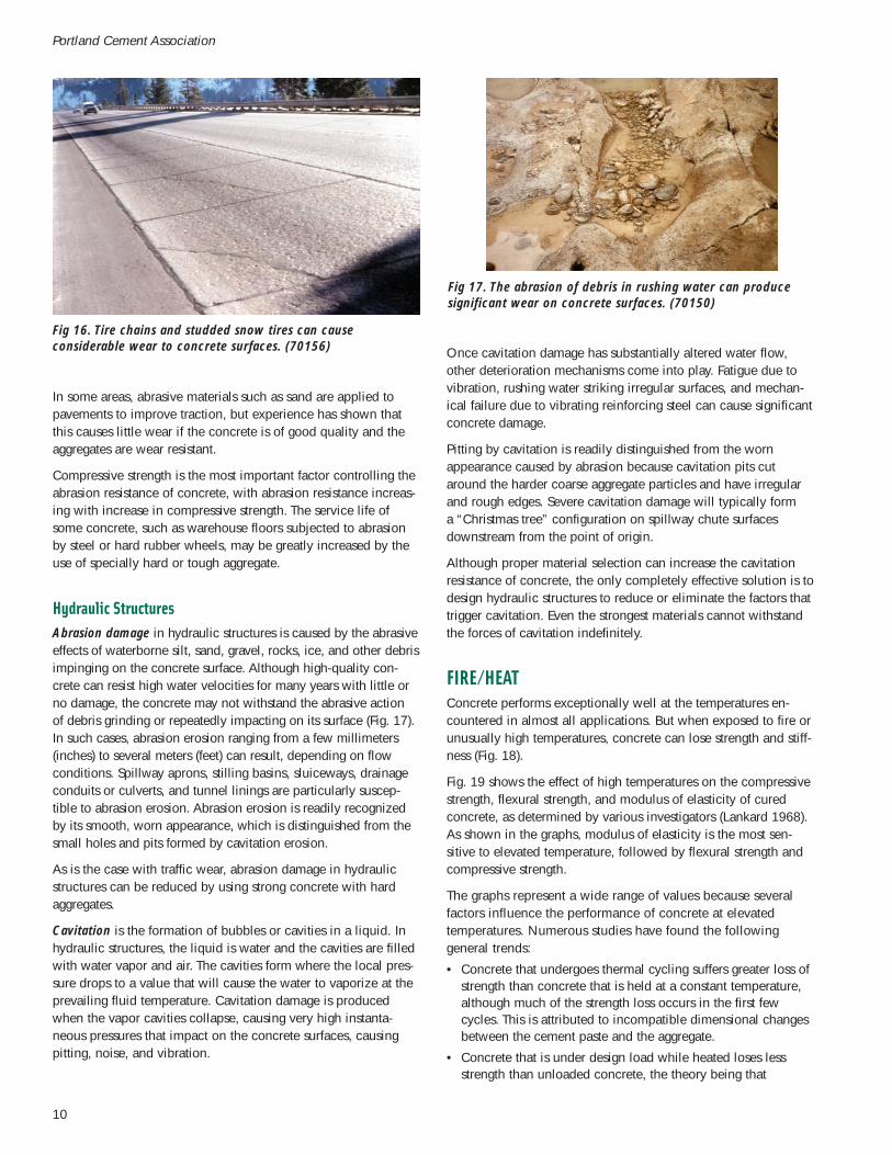
Hydraulic StructuresAbrasion damage in hydraulic structures is caused by the abrasiveeffects of waterborne silt, sand, gravel, rocks, ice, and other debrisimpinging on the concrete surface. Although high-quality con-crete can resist high water velocities for many years with little orno damage, the concrete may not withstand the abrasive actionof debris grinding or repeatedly impacting on its surface (Fig. 17).In such cases, abrasion erosion ranging from a few millimeters(inches) to several meters (feet) can result, depending on flowconditions. Spillway aprons, stilling basins, sluiceways, drainageconduits or culverts, and tunnel linings are particularly suscep-tible to abrasion erosion. Abrasion erosion is readily recognizedby its smooth, worn appearance, which is distinguished from thesmall holes and pits formed by cavitation erosion.
As is the case with traffic wear, abrasion damage in hydraulicstructures can be reduced by using strong concrete with hardaggregates.
Cavitation is the formation of bubbles or cavities in a liquid. Inhydraulic structures, the liquid is water and the cavities are filledwith water vapor and air. The cavities form where the local pres-sure drops to a value that will cause the water to vaporize at theprevailing fluid temperature. Cavitation damage is producedwhen the vapor cavities collapse, causing very high instanta-neous pressures that impact on the concrete surfaces, causingpitting, noise, and vibration.
Fig 17. The abrasion of debris in rushing water can producesignificant wear on concrete surfaces. (70150)
Once cavitation damage has substantially altered water flow,other deterioration mechanisms come into play. Fatigue due tovibration, rushing water striking irregular surfaces, and mechan-ical failure due to vibrating reinforcing steel can cause significantconcrete damage.
Pitting by cavitation is readily distinguished from the wornappearance caused by abrasion because cavitation pits cutaround the harder coarse aggregate particles and have irregularand rough edges. Severe cavitation damage will typically forma “Christmas tree” configuration on spillway chute surfacesdownstream from the point of origin.
Although proper material selection can increase the cavitationresistance of concrete, the only completely effective solution is todesign hydraulic structures to reduce or eliminate the factors thattrigger cavitation. Even the strongest materials cannot withstandthe forces of cavitation indefinitely.
FIRE/HEATConcrete performs exceptionally well at the temperatures en-countered in almost all applications. But when exposed to fire orunusually high temperatures, concrete can lose strength and stiff-ness (Fig. 18).
Fig. 19 shows the effect of high temperatures on the compressivestrength, flexural strength, and modulus of elasticity of curedconcrete, as determined by various investigators (Lankard 1968).As shown in the graphs, modulus of elasticity is the most sen-sitive to elevated temperature, followed by flexural strength andcompressive strength.
The graphs represent a wide range of values because severalfactors influence the performance of concrete at elevatedtemperatures. Numerous studies have found the followinggeneral trends:
• Concrete that undergoes thermal cycling suffers greater loss ofstrength than concrete that is held at a constant temperature,although much of the strength loss occurs in the first fewcycles. This is attributed to incompatible dimensional changesbetween the cement paste and the aggregate.
• Concrete that is under design load while heated loses lessstrength than unloaded concrete, the theory being that

imposed compressive stresses inhibit develop-ment of cracks that would be free to develop inunrestrained concrete.
• Concrete that is allowed to cool before testingloses more compressive strength than concretethat is tested hot. Concrete loses more strengthwhen quickly cooled (quenched) from hightemperatures than when it is allowed to coolgradually.
• Concrete containing limestone and calcareousaggregates performs better at high temperaturesthan concrete containing siliceous aggregates(Abrams 1956). One study showed no differencein the performance of dolostone and limestone(Carette 1982). Another study showed the follow-ing relative aggregate performance, from best toworst: firebrick, expanded shale, limestone,gravel, sandstone and expanded slag.
• Proportional strength loss is independent of com-pressive strength of concrete.
• Concrete with a higher aggregate-cement ratiosuffers less reduction in compressive strength;however, the opposite is true for modulus ofelasticity. The lower the water-cement ratio, theless loss of elastic modulus.
• If residual water in the concrete is not allowedto evaporate, compressive strength is greatlyreduced. If heated too quickly, concrete canspall as the moisture tries to escape.
11
Types and Causes of Concrete Deterioration
Fig. 18. When exposed to fire or unusuallyhigh temperatures, concrete can losestrength and stiffness. (55707)
140
120
100
80
60
40
20
0 100 200 300 400 500 600 700 800 900 1000
0 50 100 150 200 250 300 350 400 450 500
Average value of all data
Increasing numberof thermal cycles
Heat-treating temperature, °F
Heat-treating temperature, °C
Com
pres
sive
stre
ngth
, per
cent
of
as-c
ured
, unh
eate
d re
fere
nce
stre
ngth
Measurements madeat test temperature or at
room temperature after slow coolingConcrete restrained
during heating
Concrete unrestrainedduring heating
Concrete quenched or thermally cycled
Free moisturecontained duringheating
120
100
80
60
40
20
120
100
80
60
40
20
0 100 200 300 400 500 600 700 800 900 1000
0 100 200 300 400 500 600 700 800 900 1000
0 50 100 150 200 250 300 350 400 450 500
0 50 100 150 200 250 300 350 400 450 500
Average value of all data
Average value of all data
Increasing number
of thermal cycles
Increasing numberof thermal cycles
Heat-treating temperature, °F
Heat-treating temperature, °C
Heat-treating temperature, °F
Heat-treating temperature, °C
Flex
ural
or s
treng
th, p
erce
nt o
f as
-cur
ed, u
nhea
ted
refe
renc
e va
lue
Mod
ulus
of e
last
icity
, per
cent
of
as-c
ured
, unh
eate
d re
fere
nce
valu
e
Decreasing W/Cratio
Neat cement
Fig. 19. The effect of elevated temperatures on the compressivestrength (top), flexural strength (middle), and modulus of elasticity(bottom) of concrete (Lankard 1968).
RESTRAINT TO VOLUME CHANGESConcrete changes slightly in volume for various reasons, themost common causes being fluctuations in moisture content andtemperature. Restraint to volume changes, especially contraction,can cause cracking if the tensile stresses that develop exceed thetensile strength of the concrete.
Plastic Shrinkage CrackingWhen water evaporates from the surface of freshly placedconcrete faster than it is replaced by bleed water, the surfaceconcrete shrinks. Due to the restraint provided by the concretebelow the drying surface layer, tensile stresses develop in theweak, stiffening plastic concrete, resulting in shallow cracks ofvarying depth (Fig. 20). These cracks are often fairly wide at thesurface.
Plastic shrinkage cracks can be prevented by taking measures toprevent rapid water loss from the concrete surface. Fog nozzles,plastic sheeting, windbreaks, and sunshades can all be used toprevent excessive evaporation.
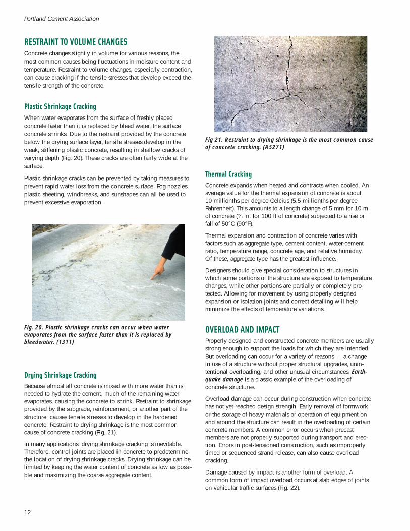
Drying Shrinkage CrackingBecause almost all concrete is mixed with more water than isneeded to hydrate the cement, much of the remaining waterevaporates, causing the concrete to shrink. Restraint to shrinkage,provided by the subgrade, reinforcement, or another part of thestructure, causes tensile stresses to develop in the hardenedconcrete. Restraint to drying shrinkage is the most commoncause of concrete cracking (Fig. 21).
In many applications, drying shrinkage cracking is inevitable.Therefore, control joints are placed in concrete to predeterminethe location of drying shrinkage cracks. Drying shrinkage can belimited by keeping the water content of concrete as low as possi-ble and maximizing the coarse aggregate content.
12
Portland Cement Association
Fig. 20. Plastic shrinkage cracks can occur when waterevaporates from the surface faster than it is replaced bybleedwater. (1311)
Fig 21. Restraint to drying shrinkage is the most common causeof concrete cracking. (A5271)
Thermal CrackingConcrete expands when heated and contracts when cooled. Anaverage value for the thermal expansion of concrete is about10 millionths per degree Celcius (5.5 millionths per degreeFahrenheit). This amounts to a length change of 5 mm for 10 mof concrete (2⁄3 in. for 100 ft of concrete) subjected to a rise orfall of 50°C (90°F).
Thermal expansion and contraction of concrete varies withfactors such as aggregate type, cement content, water-cementratio, temperature range, concrete age, and relative humidity.Of these, aggregate type has the greatest influence.
Designers should give special consideration to structures inwhich some portions of the structure are exposed to temperaturechanges, while other portions are partially or completely pro-tected. Allowing for movement by using properly designedexpansion or isolation joints and correct detailing will helpminimize the effects of temperature variations.
OVERLOAD AND IMPACTProperly designed and constructed concrete members are usuallystrong enough to support the loads for which they are intended.But overloading can occur for a variety of reasons — a changein use of a structure without proper structural upgrades, unin-tentional overloading, and other unusual circumstances. Earth-quake damage is a classic example of the overloading ofconcrete structures.
Overload damage can occur during construction when concretehas not yet reached design strength. Early removal of formworkor the storage of heavy materials or operation of equipment onand around the structure can result in the overloading of certainconcrete members. A common error occurs when precastmembers are not properly supported during transport and erec-tion. Errors in post-tensioned construction, such as improperlytimed or sequenced strand release, can also cause overloadcracking.
Damage caused by impact is another form of overload. Acommon form of impact overload occurs at slab edges of jointson vehicular traffic surfaces (Fig. 22).

Even in properly designed reinforced concrete, load-inducedtensile stresses can occur. This point is readily acknowledgedand accepted in concrete design. Current design procedures usereinforcing steel to not only carry tensile loads, but to obtainboth an adequate distribution of cracks and a reasonable limiton crack width.
LOSS OF SUPPORTLoss of support beneath concrete structures, usually caused bysettling or washout of soils and subbase materials, can cause avariety of problems in concrete structures, from cracking andperformance problems to structural failure (Fig 23). Loss ofsupport can also occur during construction due to inadequateformwork support or premature removal of forms.
A common problem related to loss of support is slab curling.Curling is the rise of a slab’s edges and corners caused bydifferences in moisture content or temperature between the topand bottom of a slab. The top dries out or cools, and contractsmore than the wetter, warmer bottom. Curling results in a lossof contact between the slab and the subbase, which can lead tocracking, slab deflection, and joint deterioration when vehiculartraffic crosses the joints.
13
Types and Causes of Concrete Deterioration
Fig. 22. A common form of impact overload occurs at slabedges of joints on vehicular traffic surfaces. (70151)
Fig. 23. Settlement can cause a variety of problems in concretestructures, from cracking and performance problems tostructural failure. (56521)
SURFACE DEFECTSVarious defects can occur on the surface of formed or finishedconcrete. Many of these defects are avoidable by using propermaterials and construction practices; others are difficult orimpossible to eliminate completely.
Formed SurfacesSurface air voids, also known as bugholes, are small cavities thatare the result of entrapped air bubbles in the surface of formedconcrete during placement and consolidation (Fig. 24). Theycan be up to 25 mm (1 in.) wide, but are usually no more than15 mm (9⁄16 in.) wide. Bug holes on vertical surfaces are morelikely to occur in sticky or stiff concrete mixes of low workabilitythat may have an excessive fine aggregate content, entrapped aircontent, or both. Also, the use of vibrators with too high of anamplitude, or the lack of complete insertion of the vibrator headmay result in an increased quantity of bug holes. Bugholes arealso aggravated by the heavy application of form release agent.
Fig. 24. Surface air voids, or bugholes, are small cavities ofentrapped air bubbles in the surface of formed concrete.(70154)
Honeycomb occurs when mortar fails to fill the spaces betweencoarse aggregates (Fig. 25). Congested reinforcement, segrega-tion, and insufficient fine aggregate contents can contributeto honeycombing. Higher concrete slumps and vibration mayassist in preventing honeycombing by increasing the flowabilityof the concrete.
Form tie holes are voids intentionally cast into concrete surfaces.A common type of form tie uses plastic cones at the formsurface. The cones act as a spreader for the forms, aid inreducing mortar leaks, and make breaking back snap ties easier.After removal, a typical cone leaves a hole in the concretesurface about 25 mm (1 in.) wide and 38 mm (11⁄2 in.) deep.Form tie holes may need to be filled to prevent leakage or toincrease concrete cover over embedded steel.
Cold joints are discontinuities in concrete members resultingfrom a delay in placement of sufficient time to prevent a union ofthe material in two successive lifts. Cold joints often result in visi-ble lines indicating the presence of a joint where one layer ofconcrete had hardened before subsequent concrete was placed(Fig. 26). Aside from their appearance, cold joints can be a
concern if they allow moisture penetration or if the loss of tensilestrength of the concrete across the joint is deemed detrimental tothe performance of the structure.
Form streaks are areas of fine or coarse aggregate left on theconcrete surface after mortar leaks through form joints and tieholes. Overvibration and the use of excessively wet or high-slump concrete increases the chances of form streaking, as dounsealed formwork joints.
Sand streaking is a streak of fine aggregate in the concrete sur-face caused by heavy bleeding along the form. It often resultsfrom the use of harsh, wet mixes, particularly those deficient inaggregate sizes of 300 µm (No. 50) and smaller.
Form offsets are abrupt to gradual surface irregularities that areusually caused by inadequate stiffness or anchorage of the formsand can be aggravated by an excessive rate of placement or byan excessively powerful vibrator.
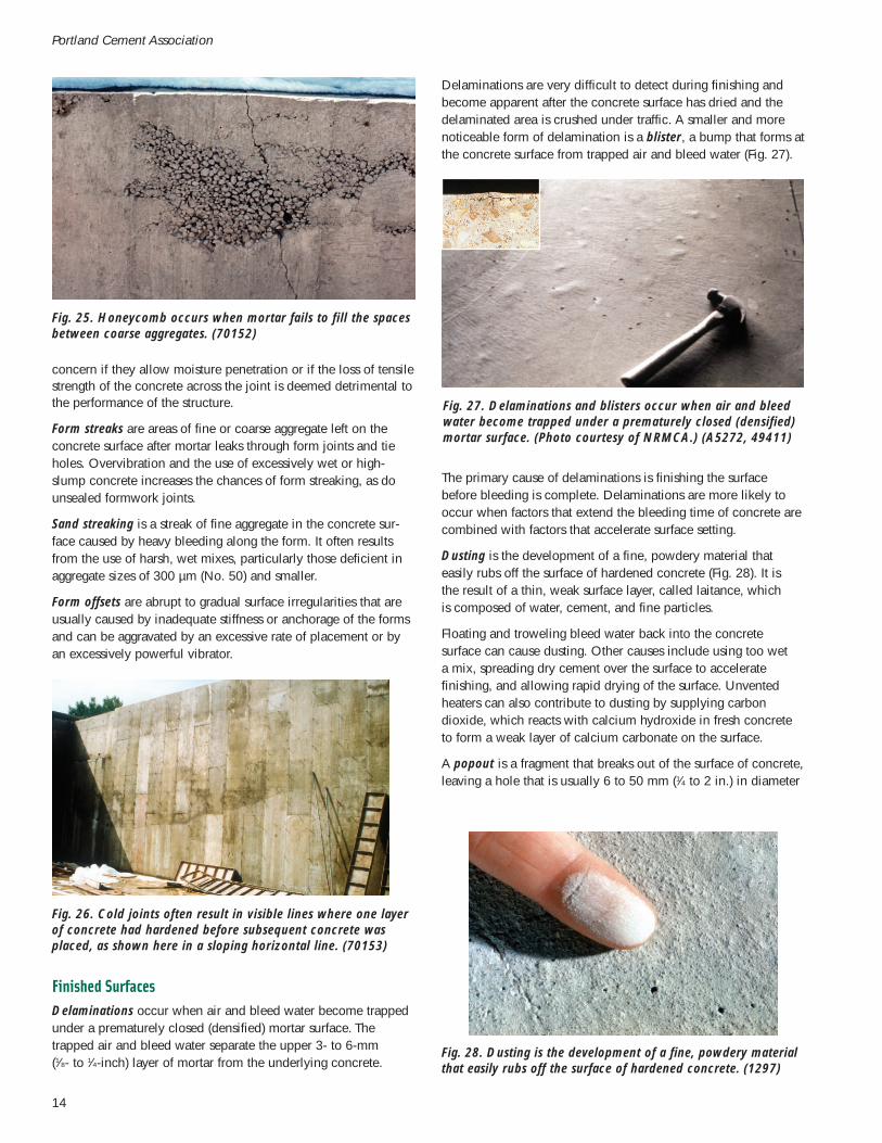
Delaminations are very difficult to detect during finishing andbecome apparent after the concrete surface has dried and thedelaminated area is crushed under traffic. A smaller and morenoticeable form of delamination is a blister, a bump that forms atthe concrete surface from trapped air and bleed water (Fig. 27).
14
Portland Cement Association
Fig. 25. Honeycomb occurs when mortar fails to fill the spacesbetween coarse aggregates. (70152)
Fig. 26. Cold joints often result in visible lines where one layerof concrete had hardened before subsequent concrete wasplaced, as shown here in a sloping horizontal line. (70153)
Fig. 27. Delaminations and blisters occur when air and bleedwater become trapped under a prematurely closed (densified)mortar surface. (Photo courtesy of NRMCA.) (A5272, 49411)
Fig. 28. Dusting is the development of a fine, powdery materialthat easily rubs off the surface of hardened concrete. (1297)
The primary cause of delaminations is finishing the surfacebefore bleeding is complete. Delaminations are more likely tooccur when factors that extend the bleeding time of concrete arecombined with factors that accelerate surface setting.
Dusting is the development of a fine, powdery material thateasily rubs off the surface of hardened concrete (Fig. 28). It isthe result of a thin, weak surface layer, called laitance, whichis composed of water, cement, and fine particles.
Floating and troweling bleed water back into the concretesurface can cause dusting. Other causes include using too weta mix, spreading dry cement over the surface to acceleratefinishing, and allowing rapid drying of the surface. Unventedheaters can also contribute to dusting by supplying carbondioxide, which reacts with calcium hydroxide in fresh concreteto form a weak layer of calcium carbonate on the surface.
A popout is a fragment that breaks out of the surface of concrete,leaving a hole that is usually 6 to 50 mm (1⁄4 to 2 in.) in diameter
Finished SurfacesDelaminations occur when air and bleed water become trappedunder a prematurely closed (densified) mortar surface. Thetrapped air and bleed water separate the upper 3- to 6-mm(1⁄8- to 1⁄4-inch) layer of mortar from the underlying concrete.

REFERENCESAbrams, M.S., Compressive Strength of Concrete at Temperaturesto 1,600F, RD016, Portland Cement Association, 1973.
ACI Committee 116, Cement and Concrete Terminology, ACI116R-90, American Concrete Institute, Farmington Hills,Michigan, 1990.
ACI Committee 201, Guide to Durable Concrete, ACI 201.2R-92,American Concrete Institute, Farmington Hills, Michigan, 1992.
ACI Committee 210, Erosion of Concrete in Hydraulic Structures,ACI 210R-93, American Concrete Institute, Farmington Hills,Michigan 1993.
ACI Committee 222, Protection of Metals in Concrete AgainstCorrosion, ACI 222R-01, American Concrete Institute,Farmington Hills, Michigan, 2001.
ACI Committee 224, Causes, Prevention, and Repair of Cracks inConcrete, ACI 224.1R-93, American Concrete Institute,Farmington Hills, Michigan, 1993.
ACI Committee 302, Guide for Concrete Floor and SlabConstruction, ACI 302.1R-96, American Concrete Institute,Farmington Hills, Michigan, 1996.
ACI Committee 309, Identification and Control of Visible Effectsof Consolidation on Formed Concrete Surfaces, ACI 309.2R-98,American Concrete Institute, Farmington Hills, Michigan, 1998.
ACI Committee 318, Building Code Requirements for StructuralConcrete, ACI 318-02, American Concrete Institute, FarmingtonHills, Michigan, 2002.
ACI Committee 515, A Guide to the Use of Waterproofing,Dampproofing, Protective, and Decorative Barrier Systems forConcrete, ACI 515.1R-79, American Concrete Institute,Farmington Hills, Michigan, 1979.
Carette, G.G., Painter, K.E., and Malhotra, V.M., “Sustained HighTemperature Effect of Concretes Made with Normal PortlandCement, Normal Portland Cement and Slag, or Normal PortlandCement and Fly Ash,” Concrete International, July 1982, pages41 to 51.
Clear, K.C., and Hay, R.E., “Time-to-Corrosion of ReinforcingSteel in Concrete Slabe, V.1: Effect of Mix Design and Construc-tion Parameters,” Report No. FHWA-RD-73-32, Federal HighwayAdministration, Washington, DC, April, 1973, 103 pages.
Clear K.C., “Time-to-Corrosion of Reinforcing Steel in ConcreteSlabs,” Federal Highway Administration, PB 258 446, Vol. 3,April, 1976.
Farny, J.A. and Kosmatka, S.H., Diagnosis and Control of Alkali-Aggregate Reactions in Concrete, IS413, Portland CementAssociation, 1997, 24 pages.
Hanley-Wood, LLC, “Chemical Attack on Hardened Concrete,”Concrete Construction, August, 1975, pages 328 to 333.
Kosmatka, S.H., Kerkhoff, B., and Panarese, W.C., Design andControl of Concrete Mixtures, EB001, Portland CementAssociation, 2002, 372 pages.
Emmons, P.H., Concrete Repair and Maintenance Illustrated, R.S.Means Co. Inc., 1993, 295 pages.
15
Types and Causes of Concrete Deterioration
Fig. 29. Subsidence cracks can develop over reinforcing steel asthe concrete settles or subsides.
Fig. 30. Crazing typically does not penetrate much below thesurface and is usually a cosmetic problem only. (4099)
(see Fig. 8). The cause of a popout usually is a piece of porousrock having a high rate of absorption and relatively low specificgravity. As the offending aggregate absorbs moisture or freezingoccurs under moist conditions, its swelling creates internalpressures sufficient to rupture the concrete surface. Pyrite, hard-burned dolomite, coal, shale, soft fine grained limestone, or chertcommonly cause popouts.
Some popouts are caused by alkali-silica reactivity. In someareas, sand-sized ASR-induced popouts are a common problemon floors that receive impermeable coverings.
Subsidence cracks may develop over embedded items, such asreinforcing steel, or adjacent to forms or hardened concrete asthe concrete settles or subsides (Fig. 29). Subsidence crackingresults from insufficient consolidation (vibration), high slumps(overly wet concrete), or a lack of adequate cover overembedded items.
Crazing is a pattern of fine cracks that do not penetrate muchbelow the surface and are usually a cosmetic problem only(Fig. 30). They are barely visible, except when the concrete isdrying after the surface has been wet. Preventing excessive evap-oration during placement and proper curing can prevent crazing.
Lankard, D.R., Birkimer, D.L., Fondriest, F.F., and Snyder, M.J.,The Effects of Moisture Content on the Constitution andStructural Properties of Portland Cement Concrete Exposed toTemperatures Up to 500°F, Battelle Memorial Institute, ColumbusLaboratories, 1968.
Malhotra, H.L., “The Effect of Temperature on the CompressiveStrength of Concrete,” Magazine of Concrete Research, August1956, pages 85 to 94.
Mehta, P. Kumar, “Sulfate Attack on Concrete: Separating Mythfrom Reality,” Concrete International, Farmington Hills,Michigan, August 2000, pages 57 to 61.
Montani, R., “Concrete’s Forgotten Enemy,” Concrete RepairDigest, December 1995/January 1996, pages 330 to 333.
PCA, Concrete Slab Surface Defects: Causes, Prevention, Repair,IS177, Portland Cement Association, 2001.
PCA, Effect of Long Exposure of Concrete to High Temperature,Portland Cement Association, 1953.
PCA, Effects of Substances on Concrete and Guide to EffectiveTreatments, IS001, Portland Cement Association, 2001, 36 pages.
Stark, D., Performance of Concrete in Sulfate Environments,RD129, Portland Cement Association, 2002
Verbeck, G. J., Carbonation of Hydrated Portland Cement,RX087, Portland Cement Association,http://www.portcement.org/pdf_files/RX087.pdf, 1958.
Whiting, D., Origins of Chloride Limits for Reinforced Concrete,PCA Serial No. 2153, Portland Cement Association,http://www.portcement.org/pdf_files/SN2153.pdf, 1997.
Woods, H., Corrosion of Embedded Material Other ThanReinforcing Steel, RX198, Portland Cement Association,http://www.portcement.org/pdf_files/RX198.pdf, 1966.
WARNING: Contact with wet (unhardened) concrete, mortar,cement, or cement mixtures can cause SKIN IRRITATION, SEVERECHEMICAL BURNS (THIRD-DEGREE), or SERIOUS EYE DAMAGE.Frequent exposure may be associated with irritant and/or allergiccontact dermatitis. Wear waterproof gloves, a long-sleeved shirt,full-length trousers, and proper eye protection when working withthese materials. If you have to stand in wet concrete, use water-proof boots that are high enough to keep concrete from flowinginto them. Wash wet concrete, mortar, cement, or cement mixturesfrom your skin immediately. Flush eyes with clean water immedi-ately after contact. Indirect contact through clothing can be as seri-ous as direct contact, so promptly rinse out wet concrete, mortar,cement, or cement mixtures from clothing. Seek immediate med-ical attention if you have persistent or severe discomfort.
This publication is intended SOLELY for use by PROFESSIONALPERSONNEL who are competent to evaluate the significance andlimitations of the information provided herein, and who will accepttotal responsibility for the application of this information. ThePortland Cement Association DISCLAIMS any and all RESPONSI-BILITY and LIABILITY for the accuracy of and the application ofthe information contained in this publication to the full extent per-mitted by law.
IS536.01
An organization of cement companies to improve andextend the uses of portland cement and concrete throughmarket development, engineering, research, education,and public affairs work.
PCA R&D Serial No. 2617© 2002 Portland Cement Association
All rights reserved