type page - e-tec.com
TRANSCRIPT

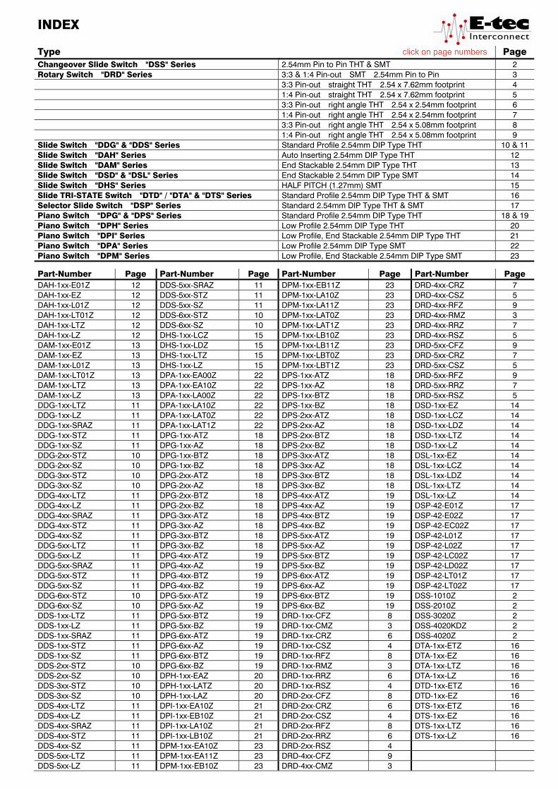
INDEX Type Page Changeover Slide Switch "DSS" Series 2.54mm Pin to Pin THT & SMT 2 Rotary Switch "DRD" Series 3:3 & 1:4 Pin-out SMT 2.54mm Pin to Pin 3 3:3 Pin-out straight THT 2.54 x 7.62mm footprint 4 1:4 Pin-out straight THT 2.54 x 7.62mm footprint 5 3:3 Pin-out right angle THT 2.54 x 2.54mm footprint 6 1:4 Pin-out right angle THT 2.54 x 2.54mm footprint 7 3:3 Pin-out right angle THT 2.54 x 5.08mm footprint 8 1:4 Pin-out right angle THT 2.54 x 5.08mm footprint 9 Slide Switch "DDG" & "DDS" Series Standard Profile 2.54mm DIP Type THT 10 & 11 Slide Switch "DAH" Series Auto Inserting 2.54mm DIP Type THT 12 Slide Switch "DAM" Series End Stackable 2.54mm DIP Type THT 13 Slide Switch "DSD" & "DSL" Series End Stackable 2.54mm DIP Type SMT 14 Slide Switch "DHS" Series HALF PITCH (1.27mm) SMT 15 Slide TRI-STATE Switch "DTD" / "DTA" & "DTS" Series Standard Profile 2.54mm DIP Type THT & SMT 16 Selector Slide Switch "DSP" Series Standard 2.54mm DIP Type THT & SMT 17 Piano Switch "DPG" & "DPS" Series Standard Profile 2.54mm DIP Type THT 18 & 19 Piano Switch "DPH" Series Low Profile 2.54mm DIP Type THT 20 Piano Switch "DPI" Series Low Profile, End Stackable 2.54mm DIP Type THT 21 Piano Switch "DPA" Series Low Profile 2.54mm DIP Type SMT 22 Piano Switch "DPM" Series Low Profile, End Stackable 2.54mm DIP Type SMT 23
Part-Number Page Part-Number Page Part-Number Page Part-Number Page DAH-1xx-E01Z 12 DDS-5xx-SRAZ 11 DPM-1xx-EB11Z 23 DRD-4xx-CRZ 7 DAH-1xx-EZ 12 DDS-5xx-STZ 11 DPM-1xx-LA10Z 23 DRD-4xx-CSZ 5 DAH-1xx-L01Z 12 DDS-5xx-SZ 11 DPM-1xx-LA11Z 23 DRD-4xx-RFZ 9 DAH-1xx-LT01Z 12 DDS-6xx-STZ 10 DPM-1xx-LAT0Z 23 DRD-4xx-RMZ 3 DAH-1xx-LTZ 12 DDS-6xx-SZ 10 DPM-1xx-LAT1Z 23 DRD-4xx-RRZ 7 DAH-1xx-LZ 12 DHS-1xx-LCZ 15 DPM-1xx-LB10Z 23 DRD-4xx-RSZ 5 DAM-1xx-E01Z 13 DHS-1xx-LDZ 15 DPM-1xx-LB11Z 23 DRD-5xx-CFZ 9 DAM-1xx-EZ 13 DHS-1xx-LTZ 15 DPM-1xx-LBT0Z 23 DRD-5xx-CRZ 7 DAM-1xx-L01Z 13 DHS-1xx-LZ 15 DPM-1xx-LBT1Z 23 DRD-5xx-CSZ 5 DAM-1xx-LT01Z 13 DPA-1xx-EA00Z 22 DPS-1xx-ATZ 18 DRD-5xx-RFZ 9 DAM-1xx-LTZ 13 DPA-1xx-EA10Z 22 DPS-1xx-AZ 18 DRD-5xx-RRZ 7 DAM-1xx-LZ 13 DPA-1xx-LA00Z 22 DPS-1xx-BTZ 18 DRD-5xx-RSZ 5 DDG-1xx-LTZ 11 DPA-1xx-LA10Z 22 DPS-1xx-BZ 18 DSD-1xx-EZ 14 DDG-1xx-LZ 11 DPA-1xx-LAT0Z 22 DPS-2xx-ATZ 18 DSD-1xx-LCZ 14 DDG-1xx-SRAZ 11 DPA-1xx-LAT1Z 22 DPS-2xx-AZ 18 DSD-1xx-LDZ 14 DDG-1xx-STZ 11 DPG-1xx-ATZ 18 DPS-2xx-BTZ 18 DSD-1xx-LTZ 14 DDG-1xx-SZ 11 DPG-1xx-AZ 18 DPS-2xx-BZ 18 DSD-1xx-LZ 14 DDG-2xx-STZ 10 DPG-1xx-BTZ 18 DPS-3xx-ATZ 18 DSL-1xx-EZ 14 DDG-2xx-SZ 10 DPG-1xx-BZ 18 DPS-3xx-AZ 18 DSL-1xx-LCZ 14 DDG-3xx-STZ 10 DPG-2xx-ATZ 18 DPS-3xx-BTZ 18 DSL-1xx-LDZ 14 DDG-3xx-SZ 10 DPG-2xx-AZ 18 DPS-3xx-BZ 18 DSL-1xx-LTZ 14 DDG-4xx-LTZ 11 DPG-2xx-BTZ 18 DPS-4xx-ATZ 19 DSL-1xx-LZ 14 DDG-4xx-LZ 11 DPG-2xx-BZ 18 DPS-4xx-AZ 19 DSP-42-E01Z 17 DDG-4xx-SRAZ 11 DPG-3xx-ATZ 18 DPS-4xx-BTZ 19 DSP-42-E02Z 17 DDG-4xx-STZ 11 DPG-3xx-AZ 18 DPS-4xx-BZ 19 DSP-42-EC02Z 17 DDG-4xx-SZ 11 DPG-3xx-BTZ 18 DPS-5xx-ATZ 19 DSP-42-L01Z 17 DDG-5xx-LTZ 11 DPG-3xx-BZ 18 DPS-5xx-AZ 19 DSP-42-L02Z 17 DDG-5xx-LZ 11 DPG-4xx-ATZ 19 DPS-5xx-BTZ 19 DSP-42-LC02Z 17 DDG-5xx-SRAZ 11 DPG-4xx-AZ 19 DPS-5xx-BZ 19 DSP-42-LD02Z 17 DDG-5xx-STZ 11 DPG-4xx-BTZ 19 DPS-6xx-ATZ 19 DSP-42-LT01Z 17 DDG-5xx-SZ 11 DPG-4xx-BZ 19 DPS-6xx-AZ 19 DSP-42-LT02Z 17 DDG-6xx-STZ 10 DPG-5xx-ATZ 19 DPS-6xx-BTZ 19 DSS-1010Z 2 DDG-6xx-SZ 10 DPG-5xx-AZ 19 DPS-6xx-BZ 19 DSS-2010Z 2 DDS-1xx-LTZ 11 DPG-5xx-BTZ 19 DRD-1xx-CFZ 8 DSS-3020Z 2 DDS-1xx-LZ 11 DPG-5xx-BZ 19 DRD-1xx-CMZ 3 DSS-4020KDZ 2 DDS-1xx-SRAZ 11 DPG-6xx-ATZ 19 DRD-1xx-CRZ 6 DSS-4020Z 2 DDS-1xx-STZ 11 DPG-6xx-AZ 19 DRD-1xx-CSZ 4 DTA-1xx-ETZ 16 DDS-1xx-SZ 11 DPG-6xx-BTZ 19 DRD-1xx-RFZ 8 DTA-1xx-EZ 16 DDS-2xx-STZ 10 DPG-6xx-BZ 19 DRD-1xx-RMZ 3 DTA-1xx-LTZ 16 DDS-2xx-SZ 10 DPH-1xx-EAZ 20 DRD-1xx-RRZ 6 DTA-1xx-LZ 16 DDS-3xx-STZ 10 DPH-1xx-LATZ 20 DRD-1xx-RSZ 4 DTD-1xx-ETZ 16 DDS-3xx-SZ 10 DPH-1xx-LAZ 20 DRD-2xx-CFZ 8 DTD-1xx-EZ 16 DDS-4xx-LTZ 11 DPI-1xx-EA10Z 21 DRD-2xx-CRZ 6 DTS-1xx-ETZ 16 DDS-4xx-LZ 11 DPI-1xx-EB10Z 21 DRD-2xx-CSZ 4 DTS-1xx-EZ 16 DDS-4xx-SRAZ 11 DPI-1xx-LA10Z 21 DRD-2xx-RFZ 8 DTS-1xx-LTZ 16 DDS-4xx-STZ 11 DPI-1xx-LB10Z 21 DRD-2xx-RRZ 6 DTS-1xx-LZ 16 DDS-4xx-SZ 11 DPM-1xx-EA10Z 23 DRD-2xx-RSZ 4 DDS-5xx-LTZ 11 DPM-1xx-EA11Z 23 DRD-4xx-CFZ 9 DDS-5xx-LZ 11 DPM-1xx-EB10Z 23 DRD-4xx-CMZ 3

PRODUCT OVERVIEW
Changeover Slide Switch
SMT & THT Page 2
Rotary Switch horizontal SMT horizontal THT vertical THT
Page 3 Page 4 & 5 Page 6 to 9
Slide Switch
DIP Package “THT”
DDG / DDS Series Page 10 & 11 DAH / DAM Series Page 12 & 13
DIP Package “SMT”
DSD / DSL Series Page 14 DHS Series Page 15
TRI-State “THT” & “SMT” Selector “THT” & “SMT”
DTD / DTA / DTS Series Page 16 DSP Series Page 17
Piano Switch
DIP Package “THT” DIP Package “SMT”
DPG / DPS Series Page 18 & 19 DPH / DPI Series Page 20 & 21 DPA / DPM Series Page 22 & 23
1
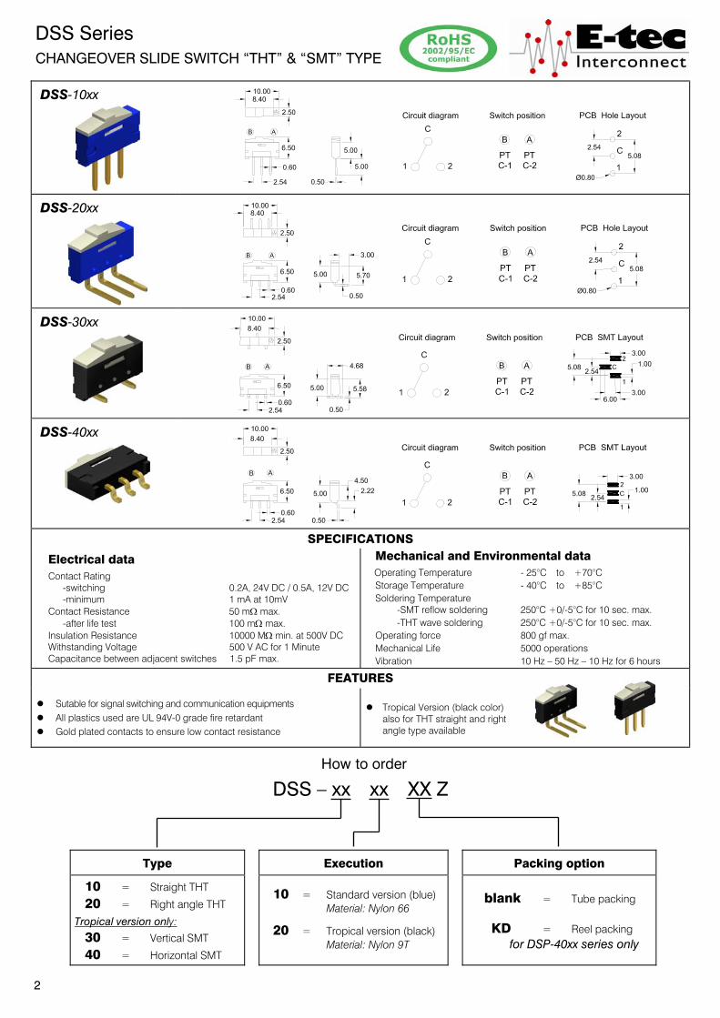
DSS Series CHANGEOVER SLIDE SWITCH “THT” & “SMT” TYPE
DSS-10xx
DSS-20xx
DSS-30xx
DSS-40xx
SPECIFICATIONS
Electrical data Contact Rating -switching 0.2A, 24V DC / 0.5A, 12V DC -minimum 1 mA at 10mV Contact Resistance 50 m: max. -after life test 100 m: max. Insulation Resistance 10000 M: min. at 500V DC Withstanding Voltage 500 V AC for 1 Minute Capacitance between adjacent switches 1.5 pF max.
Mechanical and Environmental data Operating Temperature - 25°C to +70°C
Storage Temperature - 40°C to +85°C Soldering Temperature -SMT reflow soldering 250°C +0/-5°C for 10 sec. max. -THT wave soldering 250°C +0/-5°C for 10 sec. max. Operating force 800 gf max. Mechanical Life 5000 operations Vibration 10 Hz – 50 Hz – 10 Hz for 6 hours
FEATURES
z Sutable for signal switching and communication equipments z All plastics used are UL 94V-0 grade fire retardant z Gold plated contacts to ensure low contact resistance
z Tropical Version (black color) also for THT straight and right angle type available
How to order
DSS – xx xx XX Z
Type
Execution
Packing option
10 = Straight THT
20 = Right angle THT
Tropical version only: 30 = Vertical SMT
40 = Horizontal SMT
10 = Standard version (blue) Material: Nylon 66
20 = Tropical version (black) Material: Nylon 9T
blank = Tube packing
KD = Reel packing for DSP-40xx series only
2

DRD Series 10x10 Size sealed ROTARY TYPE 3:3 & 1:4 PIN-OUT “SMT”
DRD-1 xx-XM Z (3:3 pin-out)
DRD-4 xx-XM Z (1:4 pin-out)
Construction PCB SMT Layout
3:3 PIN-OUT 1:4 PIN-OUT
SPECIFICATIONS Electrical data Contact Rating -switching 25 mA, 24 V DC -non-switching 100 mA, 50 V DC Contact Resistance -initial 50 mW max. -after life test 100 mW max. Insulation Resistance 1000 MW min. at 100 V DC Withstanding Voltage 250 V AC for 1 Minute
Mechanical and Environmental data Operating Temperature - 25°C to +70°C
Storage Temperature - 40°C to +85°C Soldering Temperature -SMT reflow soldering 250°C +0/-5°C for 10 sec. Operating Force 500 gf-cm max. (torque) Mechanical Life 2000 steps per position Vibration 10 Hz – 50 Hz – 10 Hz for 6 hours
FEATURES
l Molded-in terminals and fully sealed construction l Standard 2.54mm pin to pin l All plastics are UL 94V-0 grade fire retardant l Reliable contact and long-term stability
l Binary decimal (8 or 10 positions) and hexadecimal (16 positions), real and complementary codes available l Gold plated contacts to ensure low contact resistance.
Terminals Tin plated.
How to order
DRD – x xx – XX Z
Rotor Nbr of positions Code
1 = Flat type (3:3 pin-out)
4 = Flat type (1:4 pin-out) 08; 10; 16
RM = Real
CM = Complementary
3
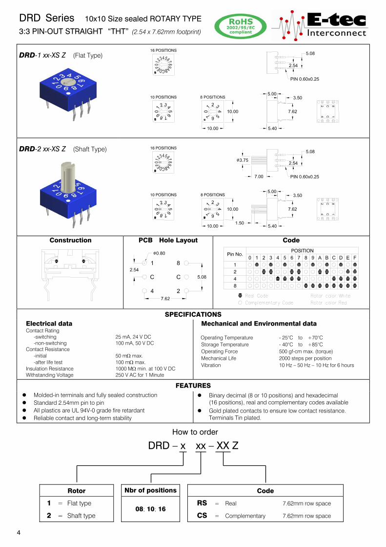
DRD Series 10x10 Size sealed ROTARY TYPE 3:3 PIN-OUT STRAIGHT “THT” (2.54 x 7.62mm footprint)
DRD-1 xx-XS Z (Flat Type)
DRD-2 xx-XS Z (Shaft Type)
Construction PCB Hole Layout Code
SPECIFICATIONS Electrical data Contact Rating -switching 25 mA, 24 V DC -non-switching 100 mA, 50 V DC Contact Resistance -initial 50 m: max. -after life test 100 m: max. Insulation Resistance 1000 M: min. at 100 V DC Withstanding Voltage 250 V AC for 1 Minute
Mechanical and Environmental data
Operating Temperature - 25°C to +70°C Storage Temperature - 40°C to +85°C Operating Force 500 gf-cm max. (torque) Mechanical Life 2000 steps per position Vibration 10 Hz – 50 Hz – 10 Hz for 6 hours
FEATURES
z Molded-in terminals and fully sealed construction z Standard 2.54mm pin to pin z All plastics are UL 94V-0 grade fire retardant z Reliable contact and long-term stability
z Binary decimal (8 or 10 positions) and hexadecimal (16 positions), real and complementary codes available z Gold plated contacts to ensure low contact resistance.
Terminals Tin plated.
How to order
DRD – x xx – XX Z
Rotor Nbr of positions Code
1 = Flat type
2 = Shaft type 08; 10; 16
RS = Real 7.62mm row space
CS = Complementary 7.62mm row space
4

DRD Series 10x10 Size sealed ROTARY TYPE 1:4 PIN-OUT STRAIGHT “THT” (2.54 x 7.62mm footprint)
DRD-4 xx-XS Z (Flat Type)
DRD-5 xx-XS Z (Shaft Type)
Construction PCB Hole Layout Code
SPECIFICATIONS Electrical data Contact Rating -switching 25 mA, 24 V DC -non-switching 100 mA, 50 V DC Contact Resistance -initial 50 m: max. -after life test 100 m: max. Insulation Resistance 1000 M: min. at 100 V DC Withstanding Voltage 250 V AC for 1 Minute
Mechanical and Environmental data
Operating Temperature - 25°C to +70°C Storage Temperature - 40°C to +85°C Operating Force 500 gf-cm max. (torque) Mechanical Life 2000 steps per position Vibration 10 Hz – 50 Hz – 10 Hz for 6 hours
FEATURES z Molded-in terminals and fully sealed construction z Standard 2.54mm pin to pin z All plastics are UL 94V-0 grade fire retardant z Reliable contact and long-term stability
z Binary decimal (8 or 10 positions) and hexadecimal (16 positions), real and complementary codes available z Gold plated contacts to ensure low contact resistance.
Terminals Tin plated.
How to order
DRD – x xx – XX Z
Rotor Nbr of positions Code
4 = Flat type
5 = Shaft type 08; 10; 16
RS = Real 7.62mm row space
CS = Complementary 7.62mm row space
5

DRD Series 10x10 Size sealed ROTARY TYPE 3:3 PIN-OUT RIGHT ANGLE “THT” (2.54 x 2.54mm footprint)
DRD-1 xx-XR Z (Flat Type)
DRD-2 xx-XR Z (Shaft Type)
Construction PCB Hole Layout Code
SPECIFICATIONS Electrical data Contact Rating -switching 25 mA, 24 V DC -non-switching 100 mA, 50 V DC Contact Resistance -initial 50 m: max. -after life test 100 m: max. Insulation Resistance 1000 M: min. at 100 V DC Withstanding Voltage 250 V AC for 1 Minute
Mechanical and Environmental data
Operating Temperature - 25°C to +70°C Storage Temperature - 40°C to +85°C Operating Force 500 gf-cm max. (torque) Mechanical Life 2000 steps per position Vibration 10 Hz – 50 Hz – 10 Hz for 6 hours
FEATURES z Molded-in terminals and fully sealed construction z Standard 2.54mm grid dimension z All plastics are UL 94V-0 grade fire retardant z Reliable contact and long-term stability
z Binary decimal (8 or 10 positions) and hexadecimal (16 positions), real and complementary codes available z Gold plated contacts to ensure low contact resistance.
Terminals Tin plated.
How to order
DRD – x xx – XX Z
Rotor Nbr of positions Code
1 = Flat type
2 = Shaft type 08; 10; 16
RR = Real 2.54mm grid
CR = Complementary 2.54mm grid
6
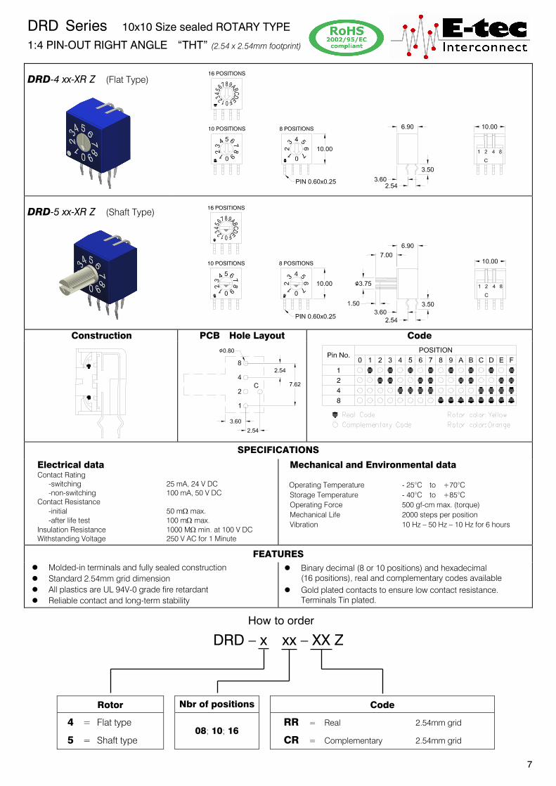
DRD Series 10x10 Size sealed ROTARY TYPE 1:4 PIN-OUT RIGHT ANGLE “THT” (2.54 x 2.54mm footprint)
DRD-4 xx-XR Z (Flat Type)
DRD-5 xx-XR Z (Shaft Type)
Construction PCB Hole Layout Code
SPECIFICATIONS
Electrical data Contact Rating -switching 25 mA, 24 V DC -non-switching 100 mA, 50 V DC Contact Resistance -initial 50 m: max. -after life test 100 m: max. Insulation Resistance 1000 M: min. at 100 V DC Withstanding Voltage 250 V AC for 1 Minute
Mechanical and Environmental data
Operating Temperature - 25°C to +70°C Storage Temperature - 40°C to +85°C Operating Force 500 gf-cm max. (torque) Mechanical Life 2000 steps per position Vibration 10 Hz – 50 Hz – 10 Hz for 6 hours
FEATURES
z Molded-in terminals and fully sealed construction z Standard 2.54mm grid dimension z All plastics are UL 94V-0 grade fire retardant z Reliable contact and long-term stability
z Binary decimal (8 or 10 positions) and hexadecimal (16 positions), real and complementary codes available z Gold plated contacts to ensure low contact resistance.
Terminals Tin plated.
How to order
DRD – x xx – XX Z
Rotor Nbr of positions Code
4 = Flat type
5 = Shaft type 08; 10; 16
RR = Real 2.54mm grid
CR = Complementary 2.54mm grid
7

DRD Series 10x10 Size sealed ROTARY TYPE 3:3 PIN-OUT RIGHT ANGLE “THT” (2.54 x 5.08mm footprint)
DRD-1 xx-XF Z (Flat Type)
DRD-2 xx-XF Z (Shaft Type)
Construction PCB Hole Layout Code
SPECIFICATIONS Electrical data Contact Rating -switching 25 mA, 24 V DC -non-switching 100 mA, 50 V DC Contact Resistance -initial 50 m: max. -after life test 100 m: max. Insulation Resistance 1000 M: min. at 100 V DC Withstanding Voltage 250 V AC for 1 Minute
Mechanical and Environmental data
Operating Temperature - 25°C to +70°C Storage Temperature - 40°C to +85°C Operating Force 500 gf-cm max. (torque) Mechanical Life 2000 steps per position Vibration 10 Hz – 50 Hz – 10 Hz for 6 hours
FEATURES
z Molded-in terminals and fully sealed construction z Standard 2.54mm pin to pin z All plastics are UL 94V-0 grade fire retardant z Reliable contact and long-term stability
z Binary decimal (8 or 10 positions) and hexadecimal (16 positions), real and complementary codes available z Gold plated contacts to ensure low contact resistance.
Terminals Tin plated.
How to order
DRD – x xx – XX Z
Rotor Nbr of positions Code
1 = Flat type
2 = Shaft type 08; 10; 16
RF = Real 5.08mm row space
CF = Complementary 5.08mm row space
8

DRD Series 10x10 Size sealed ROTARY TYPE 1:4 PIN-OUT RIGHT ANGLE “THT” (2.54 x 5.08mm footprint)
DRD-4 xx-XF Z (Flat Type)
DRD-5 xx-XF Z (Shaft Type)
Construction PCB Hole Layout Code
SPECIFICATIONS Electrical data Contact Rating -switching 25 mA, 24 V DC -non-switching 100 mA, 50 V DC Contact Resistance -initial 50 m: max. -after life test 100 m: max. Insulation Resistance 1000 M: min. at 100 V DC Withstanding Voltage 250 V AC for 1 Minute
Mechanical and Environmental data
Operating Temperature - 25°C to +70°C Storage Temperature - 40°C to +85°C Operating Force 500 gf-cm max. (torque) Mechanical Life 2000 steps per position Vibration 10 Hz – 50 Hz – 10 Hz for 6 hours
FEATURES
z Molded-in terminals and fully sealed construction z Standard 2.54mm pin to pin z All plastics are UL 94V-0 grade fire retardant z Reliable contact and long-term stability
z Binary decimal (8 or 10 positions) and hexadecimal (16 positions), real and complementary codes available z Gold plated contacts to ensure low contact resistance.
Terminals Tin plated.
How to order
DRD – x xx – XX Z
Rotor Nbr of positions Code
4 = Flat type
5 = Shaft type 08; 10; 16
RF = Real 5.08mm row space
CF = Complementary 5.08mm row space
9
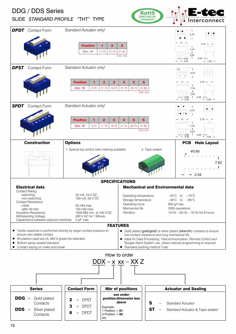
DDG / DDS Series SLIDE STANDARD PROFILE “THT” TYPE
DPDT Contact Form
Standard Actuator only!
DPST Contact Form
Standard Actuator only!
SPDT Contact Form
Standard Actuator only!
Construction Options PCB Hole Layout
1. Special top and/or side marking available 2. Tape sealed
SPECIFICATIONS Electrical data Contact Rating -switching 25 mA, 24 V DC -non-switching 100 mA, 50 V DC Contact Resistance -initial 50 m: max. -after life test 100 m: max. Insulation Resistance 1000 M: min. at 100 V DC Withstanding Voltage 500 V AC for 1 Minute Capacitance between adjacent switches 5 pF max.
Mechanical and Environmental data
Operating temperature - 25°C to +70°C Storage temperature - 40°C to +85°C Operating force 800 gf max. Mechanical life 2000 operations Vibration 10 Hz – 50 Hz – 10 Hz for 6 hours
FEATURES z Tactile response is performed directly by larger contact pressureġto ensure very stable contact z All plastics used are UL 94V-0 grade fire retardant z Bottom epoxy sealed standard z Contact wiping on make and break
z Gold plated (gold/gold) or silver plated (silver/tin) contacts to ensure low contact resistanceġandġlong mechanical life z Ideal for Data Processing, Telecommunication, Remote Control andġġ Burglar Alarm System use, where manual programming is required z Standard packing method Tube
How to order
DDX – x xx – XX Z
Series Contact Form Nbr of positions Actuator and Sealing
DDG = Gold plated Contacts
DDS = Silver plated Contacts
2 = DPST
3 = SPDT
6 = DPDT
see under position/dimension box
above
Example: 1 Position = 01 2 Position = 02 etc.
S = Standard Actuator
ST = Standard Actuator & Tape sealed
10
Position 1 2 3
Dim. "A" 11.70 21.70 31.80
Unit: mm
Position 1 2 3 4 5 6
Dim. "A" 6.70 11.70 16.70 21.70 26.70 31.80
Unit: mm
Position 1 2 3 4 5 6
Dim. "A" 6.70 11.70 16.70 21.70 26.70 31.80
Unit: mm

DDG / DDS Series SLIDE STANDARD PROFILE “THT” TYPE 3PST Contact Form
Standard Actuator only!
4PST Contact Form
Standard Actuator only!
SPST Contact Form
Standard & Low Actuator possible.
Construction Options PCB Hole Layout
1. Right Angle for SPST Contact Form; 1 to 15 positions 2. Low profile
actuator 3. Tape sealed
SPECIFICATIONS
Electrical data Contact Rating -switching 25 mA, 24 V DC -non-switching 100 mA, 50 V DC Contact Resistance -initial 50 m: max. -after life test 100 m: max. Insulation Resistance 1000 M: min. at 100 V DC Withstanding Voltage 500 V AC for 1 Minute Capacitance between adjacent switches 5 pF max.
Mechanical and Environmental data
Operating temperature - 25°C to +70°C Storage temperature - 40°C to +85°C Operating force 800 gf max. Mechanical life 2000 operations Vibration 10 Hz – 50 Hz – 10 Hz for 6 hours
FEATURES z Tactile response is performed directly by larger contact pressureġto ensure very stable contact z All plastics used are UL 94V-0 grade fire retardant z Bottom epoxy sealed standard z Contact wiping on make and break
z Gold plated (gold/gold) or silver plated (silver/tin) contacts to ensure low contact resistanceġandġlong mechanical life z Ideal for Data Processing, Telecommunication, Remote Control andġġ Burglar Alarm System use, where manual programming is required z Standard packing method Tube
How to order
DDX – x xx – XXX Z
Series Contact Form Nbr of positions Actuator and Sealing
DDG = Gold plated Contacts
DDS = Silver plated Contacts
1 = SPST 4 = 3PST 5 = 4PST
see under position/dimension box
above Example: 1 Position = 01 2 Position = 02 etc.
S = Standard Actuator L = Low Profile Actuator LT = Low Profile Actuator & Tape sealed ST = Standard Actuator & Tape sealed SRA = Right Angle Type
11
Position 1 2 3 4 5 6 Dim. "A" 3.91 6.70 9.20 11.70 14.20 16.70
Position 7 8 9 10 12 15 Dim. "A" 19.20 21.70 24.20 26.70 31.80 39.50
Unit: mm
Position 1 2 3 4
Dim. "A" 9.20 16.70 24.20 31.80
Unit: mm
Position 1 2 3
Dim. "A" 11.70 21.70 31.80
Unit: mm
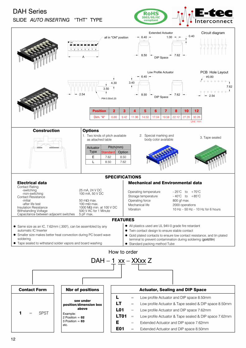
DAH Series SLIDE AUTO INSERTING “THT” TYPE
Construction Options
1. Two kinds of pitch available as attached table
2. Special marking and body color available
3. Tape sealed
SPECIFICATIONS Electrical data Contact Rating -switching 25 mA, 24 V DC -non-switching 100 mA, 50 V DC Contact Resistance -initial 50 m: max. -after life test 100 m: max. Insulation Resistance 1000 M: min. at 100 V DC Withstanding Voltage 500 V AC for 1 Minute Capacitance between adjacent switches 5 pF max.
Mechanical and Environmental data
Operating temperature - 25°C to +70°C
Storage temperature - 40°C to +85°C
Operating force 800 gf max.
Mechanical life 2000 operations
Vibration 10 Hz – 50 Hz – 10 Hz for 6 hours
FEATURES
z Same size as an IC, 7.62mm (.300"), can be assembled by any automaticġIC Inserter
z Smaller size makes better heat convection during PC boardġwave soldering
z Tape sealed to withstand solder vapors and board washing
z All plastics used are UL 94V-0 grade fire retardant
z Twin contact design to ensure stable contact
z Gold plated contacts to ensure low contact resistance,ġand tin plated terminal to prevent contamination during soldering (gold/tin)
z Standard packing method Tube
How to order
DAH – 1 xx – XXxx Z
Contact Form Nbr of positions Actuator, Sealing and DIP Space
1 = SPST
see under position/dimension box
above
Example: 2 Position = 02 3 Position = 03 etc.
L = Low profile Actuator and DIP space 8.50mm
LT = Low profile Actuator & Tape sealed & DIP space 8.50mm
L01 = Low profile Actuator and DIP space 7.62mm
LT01 = Low profile Actuator & Tape sealed & DIP space 7.62mm
E = Extended Actuator and DIP space 7.62mm
E01 = Extended Actuator and DIP space 8.50mm
12
Position 2 3 4 5 6 7 8 10 12
Dim. "A" 6.68 9.42 11.96 14.50 17.04 19.58 22.12 27.20 32.28
Unit: mm
Actuator Type
Pitch(mm)
Standard Option E 7.62 8.50
L 8.50 7.62

DAM Series SLIDE END STACKABLE “THT” TYPE
Construction Options
1. Two kinds of pitch available as attached table
2. Special marking and body color available
3. Tape sealed
SPECIFICATIONS Electrical data Contact Rating -switching 25 mA, 24 V DC -non-switching 100 mA, 50 V DC Contact Resistance -initial 50 m: max. -after life test 100 m: max. Insulation Resistance 1000 M: min. at 100 V DC Withstanding Voltage 500 V AC for 1 Minute Capacitance between adjacent switches 5 pF max.
Mechanical and Environmental data
Operating temperature - 25°C to +70°C
Storage temperature - 40°C to +85°C
Operating force 800 gf max.
Mechanical life 2000 operations
Vibration 10 Hz – 50 Hz – 10 Hz for 6 hours
FEATURES
z End stackable for standard 2.54mm (.100") integrated circuit pitch
z Same size as an IC, 7.62mm (.300"), can be assembled by any automaticġIC Inserter
z Tape sealed to withstand solder vapors and board washing
z All plastics used are UL 94V-0 grade fire retardant
z Twin contact design to ensure stable contact
z Gold plated contacts to ensure low contact resistance,ġand tin plated terminal to prevent contamination during soldering (gold/tin)
z Standard packing method Tube
How to order
DAM – 1 xx – XXxx Z
Contact Form Nbr of positions Actuator, Sealing and DIP Space
1 = SPST
see under position/dimension box
above
Example: 1 Position = 01 2 Position = 02 etc.
L = Low profile Actuator and DIP space 8.50mm
LT = Low profile Actuator & Tape sealed & DIP space 8.50mm
L01 = Low profile Actuator and DIP space 7.62mm
LT01 = Low profile Actuator & Tape sealed & DIP space 7.62mm
E = Extended Actuator and DIP space 7.62mm
E01 = Extended Actuator and DIP space 8.50mm
13
Actuator Type
Pitch(mm)
Standard Option E 7.62 8.50
L 8.50 7.62
Position 1 2 3 4 5 6 7 8 9 10 12
Dim. "A" 2.50 5.04 7.58 10.12 12.66 15.20 17.74 20.28 22.82 25.36 30.43
Unit: mm

DSD / DSL Series SLIDE END STACKABLE “SMT” TYPE DSD Gull Wing Type
DSL J-Leg Type
Construction PCB SMT Layout Options
DSD DSL
1. Special marking and body color available 2. Tape sealed
SPECIFICATIONS
Electrical data Contact Rating -switching 25 mA, 24 V DC -non-switching 100 mA, 50 V DC Contact Resistance -initial 50 m: max. -after life test 100 m: max. Insulation Resistance 1000 M: min. at 100 V DC Withstanding Voltage 500 V AC for 1 Minute Capacitance between adjacent switches 5 pF max.
Mechanical and Environmental data Operating Temperature - 25°C to +70°C
Storage Temperature - 40°C to +85°C Soldering Temperature -SMT reflow soldering 250°C +0/-5°C for 10 sec. Operating Force 800 gf max. Mechanical Life 2000 operations Vibration 10 Hz – 50 Hz – 10 Hz for 6 hours
FEATURES
z End stackable for standard 2.54mm (.100") integrated circuit pitch z Tape sealed to withstand solder vapors and board washing z All plastics used are UL 94V-0 grade fire retardant
z Twin contact design to ensure stable contact z Gold plated contacts to ensure low contact resistance,ġand tin plated terminal to prevent contamination during soldering (gold/tin)
How to order
DSX – 1 xx – XX Z
Series Nbr of positions Actuator, Sealing and Packing
DSD = Gull Wing Type
DSL = J-Leg Type
see under
position/dimension box above
Example: 1 Position = 01 2 Position = 02 etc.
L = Low Profile Actuator; Tube packing
LT = Low Profile Actuator & Tape sealed; Tube packing LC = Low Profile Actuator; Reel packing
LD = Low Profile Actuator & Tape sealed; Reel packing
E = Extended Actuator; Tube packing
14
Position 1 2 3 4 5 6 7 8 9 10 12
Dim. "A" 2.50 5.04 7.58 10.12 12.66 15.20 17.74 20.28 22.82 25.36 30.43
DSL Series: 1 position switch is not available Unit: mm

DHS Series SLIDE HALF PITCH (1.27mm) “SMT” TYPE
Construction PCB SMT Layout Options
1. Special marking and body color available 2. Tape sealed
SPECIFICATIONS Electrical data Contact Rating
-switching 25 mA, 24 V DC
-non-switching 100 mA, 50 V DC
Contact Resistance
-initial 50 m: max.
-after life test 100 m: max.
Insulation Resistance 500 M: min. at 100 V DC
Withstanding Voltage 300 V AC for 1 Minute
Capacitance between adjacent switches 5 pF max.
Mechanical and Environmental data Operating Temperature - 25°C to +70°C
Storage Temperature - 40°C to +85°C
Soldering Temperature
-SMT reflow soldering 250°C +0/-5°C for 10 sec.
Operating Force 800 gf max.
Mechanical Life 1000 operations
Vibration 10 Hz – 50 Hz – 10 Hz for 6 hours
FEATURES
z End stackable for standard 1.27mm (.050˝) integrated circuit pitch
z Lowest profile DIP Switch, only 1.80mm above PCB
z Tape sealed to withstand solder vapors and board washing
z All plastics used are UL 94V-0 grade fire retardant
z Gold plated contacts, contact & solder area (gold/gold), to ensure
low contact resistance
How to order
DHS – x xx – XX Z
Contact Form Nbr of positions Actuator, Sealing and Packing
1 = SPST
see under position/dimension box
above
Example: 1 Position = 02 2 Position = 04 etc.
L = Low Profile Actuator; Tube packing
LT = Low Profile Actuator & Tape sealed; Tube packing
LC = Low Profile Actuator; Reel packing
LD = Low Profile Actuator & Tape sealed; Reel packing
15
Position 2 4 6 8 10
Dim. "A" 3.70 6.20 8.75 11.30 13.80
Unit: mm

DTD / DTA / DTS Series SLIDE TRI-STATE “THT” & “SMT” TYPE DTD
DTA
DTS
Construction PCB Hole/SMT Layout Options
DTD DTA DTS DTD / DTA DTS 1. Tape sealed 2. Reverse PCB Layout available
SPECIFICATIONS Electrical data Contact Rating -switching 25 mA, 24 V DC -non-switching 100 mA, 50 V DC Contact Resistance -initial 50 m: max. -after life test 100 m: max. Insulation Resistance 1000 M: min. at 100 V DC Withstanding Voltage 500 V AC for 1 Minute Capacitance between adjacent switches 5 pF max.
Mechanical and Environmental data
Operating temperature - 25°C to +70°C
Storage temperature - 40°C to +85°C
Operating force 800 gf max.
Mechanical life 2000 operations
Vibration 10 Hz – 50 Hz – 10 Hz for 6 hours
FEATURES
z With three state (1-open-0) setting function, especially suitable for encoding/decoding of tri-state encoder/decoder integrated circuit to obtain more security codes than traditional two-state (1-0) operation. For instance, 9 bits with tri-state gets 19,683 (39) codes, while two-state has 512 (29) codes, gains 38 times in former
z All plastics used are UL 94V-0 grade fire retardant
z Gold plated contacts to ensure low contact resistance,ʳand tin plated terminal to prevent contamination during soldering (gold/tin) z Twin contacts designed to ensure stable contact z Ideal for Telecommunication, Transmitter, Remote Control and Burglar Alarm Systems which use integrated circuits with tri-state coding systems z Standard packing method Tube
How to order
DTX – 1 xx – XX Z
Series Nbr of positions Actuator and Sealing
DTD = Bottom Epoxy Sealed THT Type
DTA = Low Profile THT Type
DTS = Low Profile SMT Type
see under position/dimension box
above
Example: 2 Position = 02 3 Position = 03 etc.
E = Extended Actuator
ET = Extended Actuator & Tape sealed
Low Profile Actuator for DTA & DTS Series only! L = Low Profile Actuator
LT = Low Profile Actuator & Tape sealed
16
Position 4 5 6 7
Dim. "A" 15.30 17.84 20.38 22.92
Position 8 9 10
Dim. "A" 25.46 28.00 30.54
Unit: mm
Position 2 3 4 5
Dim. "A" 6.88 9.42 11.96 14.50
Position 6 7 8 9
Dim. "A" 17.04 19.58 22.12 24.66
Position 10 12
Dim. "A" 27.20 32.28
Unit: mm

DSP Series SELECTOR SLIDE SWITCH “THT” & “SMT” TYPE
DSP-42-XX 01 Z (THT Type)
DSP-42-XX 02 Z (SMT Type)
PCB Layout Option Tape sealed
Application DSP-42-XX 01 Z (THT Type) DSP-42-XX 02 Z (SMT Type)
Ideal as Function and Band Selector Switch in
Radio-Cassette, Recorder, Office Equipment, TV sets,
VCR etc.
SPECIFICATIONS Electrical data Contact Rating
-switching 25 mA, 24 V DC
-non-Switching 100 mA, 50 V DC
Contact Resistance
-initial 50 m: max.
-after life test 100 m: max.
Insulation Resistance 1000 M: min. at 100 V DC
Withstanding Voltage 500 V AC for 1 Minute
Capacitance between adjacent switches 5 pF max.
Mechanical and Environmental data Operating Temperature - 25°C to +70°C
Storage Temperature - 40°C to +85°C
Soldering Temperature
-SMT reflow soldering 250°C +0/-5°C for 10 sec. max.
-THT wave soldering 250°C +0/-5°C for 10 sec. max.
Operating Force 100 gf min / 1000 gf max.
Mechanical Life 2000 operations
Vibration 10 Hz – 50 Hz – 10 Hz for 6 hours
FEATURES
z Same size as an IC, 7.62mm (.300"), can be assembled by
any automatic IC Inserter
z Top tape sealed to withstand solder vapors and board washing
z All plastics used are UL 94V-0 grade fire retardant
z Gold plated contacts to ensure low contact resistance and
tin plated terminal to prevent contamination during soldering
How to order
DSP – 42 – XX xx Z
Contact Form
Device Type, Actuator, DIP Space & Packing
42 = 4PDT
L LT E
01 = THT Type; Low Profile Actuator DIP space 8.50mm; Tube packing
01 = THT Type; Low Profile Actuator DIP space 8.50mm; Top sealed; Tube packing
01 = THT Type; Extended Actuator DIP space 7.62mm; Tube packing
L LT LC LD E EC
02 = SMT Type; Low Profile Actuator; Tube packing
02 = SMT Type; Low Profile Actuator; Top sealed; Tube packing 02 = SMT Type; Low Profile Actuator; Reel packing
02 = SMT Type; Low Profile Actuator; Top sealed; Reel packing
02 = SMT Type; Extended Actuator; Tube packing
02 = SMT Type; Extended Actuator; Reel packing
17
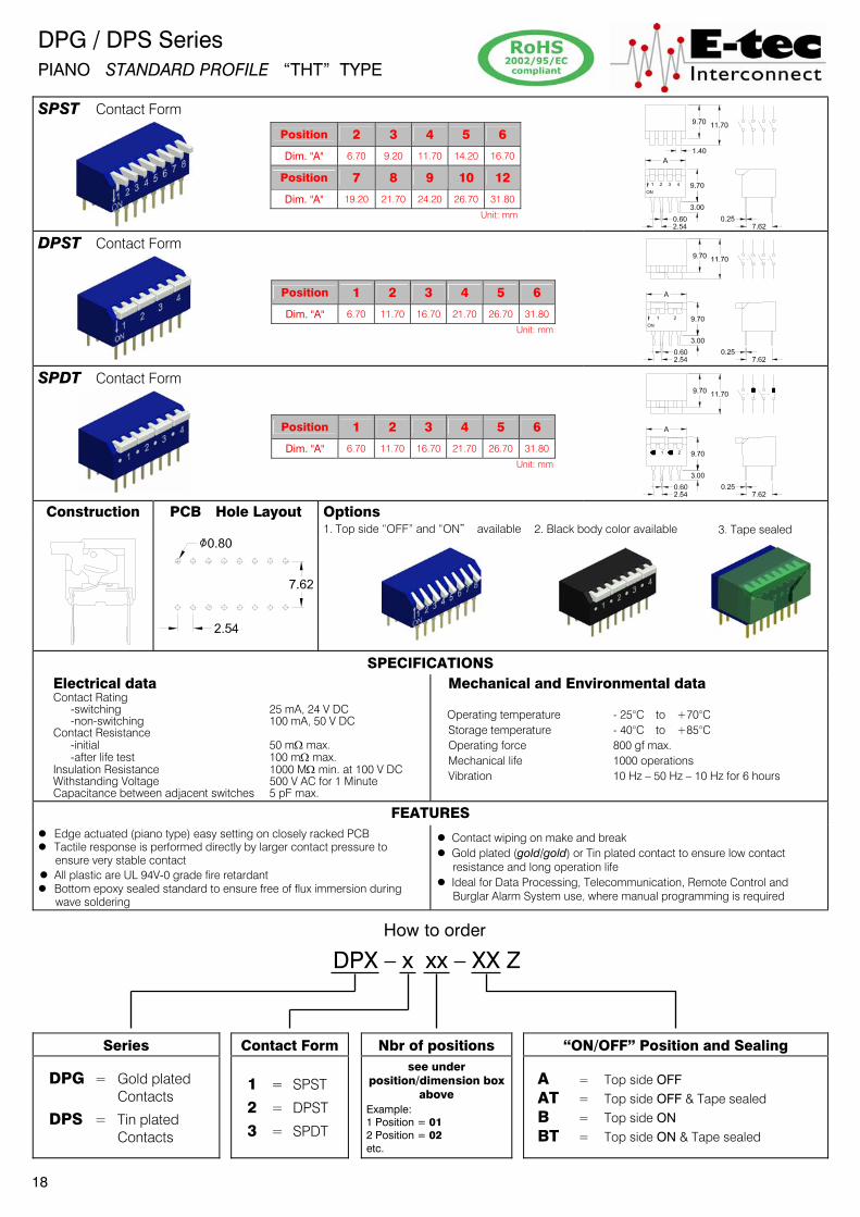
DPG / DPS Series PIANO STANDARD PROFILE “THT” TYPE
SPST Contact Form
DPST Contact Form
SPDT Contact Form
Construction PCB Hole Layout Options
1. Top side “OFF” and “ONȿ available 2. Black body color available 3. Tape sealed
SPECIFICATIONS Electrical data Contact Rating -switching 25 mA, 24 V DC -non-switching 100 mA, 50 V DC Contact Resistance -initial 50 m: max. -after life test 100 m: max. Insulation Resistance 1000 M: min. at 100 V DC Withstanding Voltage 500 V AC for 1 Minute Capacitance between adjacent switches 5 pF max.
Mechanical and Environmental data
Operating temperature - 25°C to +70°C Storage temperature - 40°C to +85°C Operating force 800 gf max. Mechanical life 1000 operations Vibration 10 Hz – 50 Hz – 10 Hz for 6 hours
FEATURES
z Edge actuated (piano type) easy setting on closely racked PCB z Tactile response is performed directly by larger contact pressure to
ensure very stable contact z All plastic are UL 94V-0 grade fire retardant z Bottom epoxy sealed standard to ensure free of flux immersion during
wave soldering
z Contact wiping on make and break z Gold plated (gold/gold) or Tin plated contact to ensure low contact
resistance and long operation life z Ideal for Data Processing, Telecommunication, Remote Control and
Burglar Alarm System use, where manual programming is required
How to order
DPX – x xx – XX Z
Series Contact Form Nbr of positions “ON/OFF” Position and Sealing
DPG = Gold plated Contacts
DPS = Tin plated Contacts
1 = SPST
2 = DPST
3 = SPDT
see under position/dimension box
above Example: 1 Position = 01 2 Position = 02 etc.
A = Top side OFF AT = Top side OFF & Tape sealed B = Top side ON BT = Top side ON & Tape sealed
18
Position 1 2 3 4 5 6
Dim. "A" 6.70 11.70 16.70 21.70 26.70 31.80
Unit: mm
Position 1 2 3 4 5 6
Dim. "A" 6.70 11.70 16.70 21.70 26.70 31.80
Unit: mm
Position 2 3 4 5 6
Dim. "A" 6.70 9.20 11.70 14.20 16.70
Position 7 8 9 10 12
Dim. "A" 19.20 21.70 24.20 26.70 31.80
Unit: mm
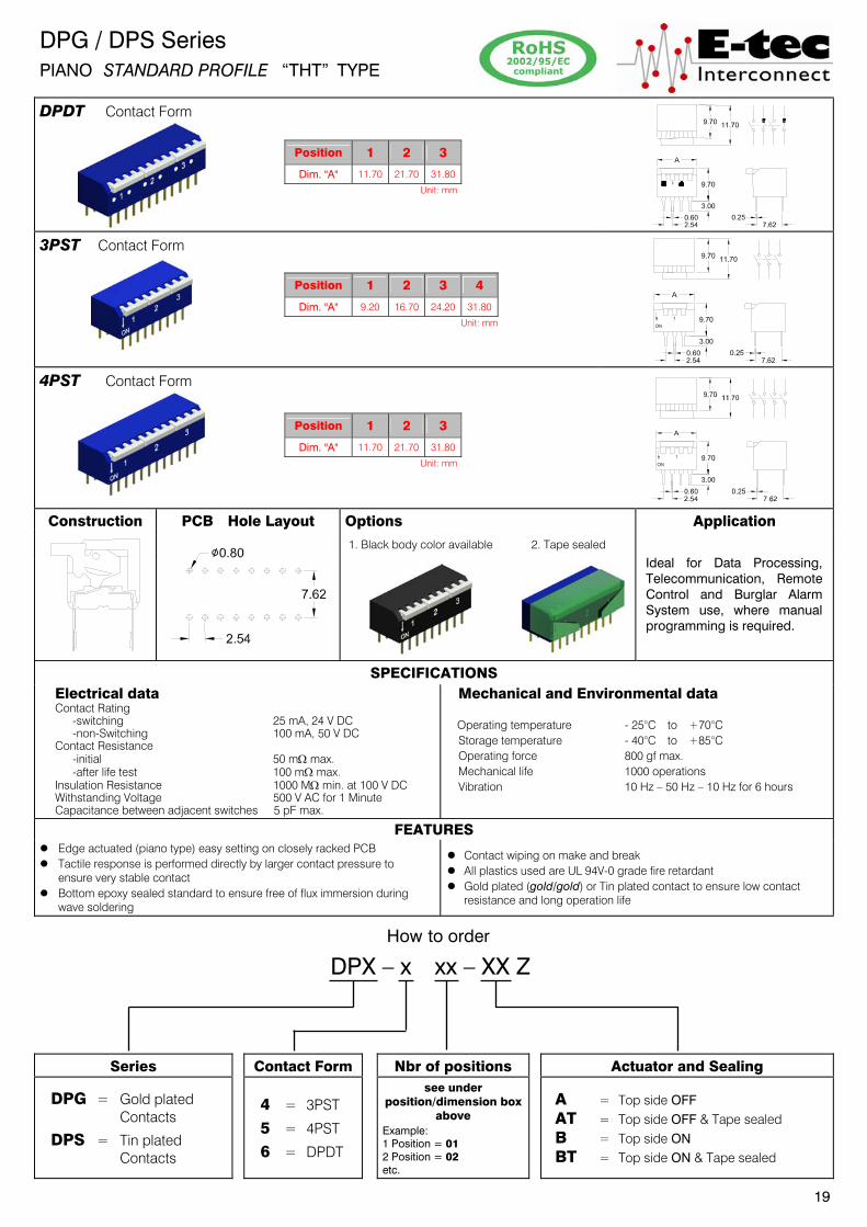
DPG / DPS Series PIANO STANDARD PROFILE “THT” TYPE
DPDT Contact Form
3PST Contact Form
4PST Contact Form
Construction PCB Hole Layout Options Application
1. Black body color available 2. Tape sealed
Ideal for Data Processing, Telecommunication, Remote Control and Burglar Alarm System use, where manual programming is required.
SPECIFICATIONS Electrical data Contact Rating -switching 25 mA, 24 V DC -non-Switching 100 mA, 50 V DC Contact Resistance -initial 50 m: max. -after life test 100 m: max. Insulation Resistance 1000 M: min. at 100 V DC Withstanding Voltage 500 V AC for 1 Minute Capacitance between adjacent switches 5 pF max.
Mechanical and Environmental data
Operating temperature - 25°C to +70°C
Storage temperature - 40°C to +85°C
Operating force 800 gf max.
Mechanical life 1000 operations
Vibration 10 Hz – 50 Hz – 10 Hz for 6 hours
FEATURES
z Edge actuated (piano type) easy setting on closely racked PCB
z Tactile response is performed directly by larger contact pressure to ensure very stable contact
z Bottom epoxy sealed standard to ensure free of flux immersion during wave soldering
z Contact wiping on make and break
z All plastics used are UL 94V-0 grade fire retardant
z Gold plated (gold/gold) or Tin plated contact to ensure low contact resistance and long operation life
How to order
DPX – x xx – XX Z
Series Contact Form Nbr of positions Actuator and Sealing
DPG = Gold plated Contacts
DPS = Tin plated Contacts
4 = 3PST
5 = 4PST
6 = DPDT
see under position/dimension box
above Example: 1 Position = 01 2 Position = 02 etc.
A = Top side OFF
AT = Top side OFF & Tape sealed
B = Top side ON
BT = Top side ON & Tape sealed
19
Position 1 2 3
Dim. "A" 11.70 21.70 31.80
Unit: mm
Position 1 2 3
Dim. "A" 11.70 21.70 31.80
Unit: mm
Position 1 2 3 4
Dim. "A" 9.20 16.70 24.20 31.80
Unit: mm
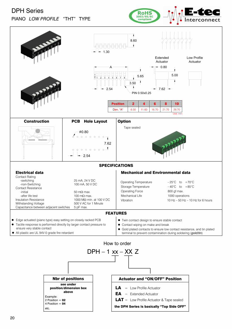
DPH Series PIANO LOW PROFILE “THT” TYPE
Construction PCB Hole Layout Option
Tape sealed
SPECIFICATIONS
Electrical data Contact Rating -switching 25 mA, 24 V DC -non-Switching 100 mA, 50 V DC Contact Resistance -initial 50 m: max. -after life test 100 m: max. Insulation Resistance 1000 M: min. at 100 V DC Withstanding Voltage 500 V AC for 1 Minute Capacitance between adjacent switches 5 pF max.
Mechanical and Environmental data Operating Temperature - 25°C to +70°C
Storage Temperature - 40°C to +85°C Operating Force 800 gf max. Mechanical Life 1000 operations Vibration 10 Hz – 50 Hz – 10 Hz for 6 hours
FEATURES
z Edge actuated (piano type) easy setting on closely racked PCB z Tactile response is performed directly by larger contact pressure to
ensure very stable contact z All plastic are UL 94V-0 grade fire retardant
z Twin contact design to ensure stable contact z Contact wiping on make and break z Gold plated contacts to ensure low contact resistance,ġand tin plated terminal to prevent contamination during soldering (gold/tin)
How to order
DPH – 1 xx – XX Z
Nbr of positions Actuator and “ON/OFF” Position
see under position/dimension box
above
Example: 2 Position = 02 4 Position = 04
etc.
LA = Low Profile Actuator
EA = Extended Actuator
LAT = Low Profile Actuator & Tape sealed
the DPH Series is basically “Top Side OFF”
20
Position 2 4 6 8 10
Dim. "A" 6.50 11.60 16.70 21.70 26.70 Unit: mm

DPI Series PIANO LOW PROFILE “THT” TYPE END STACKABLE
Construction PCB Hole Layout Precautions in Handling
Do not wash the switch!
Washable Type not available.
SPECIFICATIONS
Electrical data Contact Rating -switching 25 mA, 24 V DC -non-switching 100 mA, 50 V DC Contact Resistance -initial 100 m: max. -after life test 200 m: max. Insulation Resistance 100 M: min. at 500 V DC Withstanding Voltage 500 V AC for 1 Minute Capacitance between adjacent switches 5 pF max..
Mechanical and Environmental data
Operating Temperature - 20°C to +85°C Storage Temperature - 40°C to +85°C Operating Force 800 gf max. Mechanical Life 2000 operations Vibration 10 Hz – 50 Hz – 10 Hz for 6 hours
FEATURES
z End stackable for standard 2.54mm (.100˝) integrated circuit pitch z Twin contact design to ensure stable contact
z All plastics used are UL 94V-0 grade fire retardant
z Gold plated contacts, contact & solder area (gold/gold), to ensure low contact resistance
How to order
DPI – 1 xx – XX 1 0 Z
Nbr of positions Actuator and “ON/OFF” Position Packing
see under position/dimension box above
Example: 2 Position = 02 4 Position = 04 etc.
EA = Extended Actuator; Top side OFF
EB = Extended Actuator; Top side ON
LA = Low profile Actuator; Top side OFF
LB = Low profile Actuator; Top side ON
0 = Tube packing
21
2.54
7.62
Ø0.80
Position 2 4 6 8 10
Dim. "A" 4.98 10.06 15.15 20.22 25.30 Unit: mm

DPA Series PIANO LOW PROFILE “SMT” TYPE
Construction PCB SMT Layout Option
Tape sealed
SPECIFICATIONS
Electrical data Contact Rating -switching 25 mA, 24 V DC -non-Switching 100 mA, 50 V DC Contact Resistance -initial 50 m: max. -after life test 100 m: max. Insulation Resistance 1000 M: min. at 100 V DC Withstanding Voltage 500 V AC for 1 Minute Capacitance between adjacent switches 5 pF max.
Mechanical and Environmental data Operating Temperature - 25°C to +70°C
Storage Temperature - 40°C to +85°C Soldering Temperature -SMT reflow soldering 250°C +0/-5°C for 10 sec. Operating Force 800 gf max. Mechanical Life 1000 operations
Vibration 10 Hz – 50 Hz – 10 Hz for 6 hours
FEATURES
z Edge actuated (piano type) easy setting on closely racked PCB z Tactile response is performed directly by larger contact pressure to
ensure very stable contact z All plastic are UL 94V-0 grade fire retardant
z Twin contact design to ensure stable contact z Contact wiping on make and break z Gold plated contacts to ensure low contact resistance,ġand tin plated terminal to prevent contamination during soldering (gold/tin)
How to order
DPA – 1 xx – XX Xx Z
Nbr of positions Actuator and “ON/OFF” Position Packing and Sealing
see under position/dimension box
above
Example: 2 Position = 02 4 Position = 04
etc.
EA = Extended Actuator; Top side OFF 00 = Tube packing
10 = Reel packing
LA = Low Profile Actuator; Top side OFF
00 = Tube packing
10 = Reel packing
T0 = Tube packing & Tape sealed
T1 = Reel packing & Tape sealed
22
Position 2 4 6 8 10
Dim. "A" 6.50 11.60 16.70 21.70 26.70 Unit: mm

DPM Series
PIANO LOW PROFILE “SMT” TYPE END STACKABLE
Construction PCB SMT Layout Precautions in Handling
Do not wash the switch!
Washable Type not available.
SPECIFICATIONS
Electrical data Contact Rating -switching 25 mA, 24 V DC -non-switching 100 mA, 50 V DC Contact Resistance -initial 100 m: max. -after life test 200 m: max. Insulation Resistance 100 M: min. at 500 V DC Withstanding Voltage 500 V AC for 1 Minute Capacitance between adjacent switches 5 pF max..
Mechanical and Environmental data Operating Temperature - 20°C to +85°C
Storage Temperature - 40°C to +85°C Soldering Temperature -SMT reflow soldering 250°C +0/-5°C for 10 sec. Operating Force 800 gf max. Mechanical Life 2000 operations Vibration 10 Hz – 50 Hz – 10 Hz for 6 hours
FEATURES
z End stackable for standard 2.54mm (.100˝) integrated circuit pitch z Twin contact design to ensure stable contact
z All plastics used are UL 94V-0 grade fire retardant
z Gold plated contacts, contact & solder area (gold/gold), to ensure low contact resistance
How to order
DPM – 1 xx – XX 1 xx Z
Nbr of positions Actuator and “ON/OFF” Position Packing
see under position/dimension box above
Example:
2 Position = 02
4 Position = 04 etc.
EA = Extended Actuator; Top side OFF
EB = Extended Actuator; Top side ON
10 = Tube packing
11 = Reel packing
LA = Low profile Actuator; Top side OFF
LB = Low profile Actuator; Top side ON
10 = Tube packing
11 = Reel packing
T0 = Tube packing & Tape sealed
T1 = Reel packing & Tape sealed
23
Position 2 4 6 8 10
Dim. "A" 4.98 10.06 15.15 20.22 25.30 Unit: mm

Other products from E-tec
Please contact your closest sales office for further information.
Customized Products Test Sockets & Adapters IC - Sockets
Compact Flash Connectors USB & IEEE 1394 Connectors Mini PCI Express Connectors
D-Sub Connectors Flex Cable Connectors HDMI Connectors
Probe Pin & Probe Pin Connectors PCB Connectors Multi Media Card Connectors
Modular Plugs & Jacks Phono - & DC - Power Connectors RF - Connectors