type cfs compact fusible disconnect switches · pdf fileare available with provisions for...
TRANSCRIPT

Disconnect Switches Product Guide
www.usa.siemens.com/switches
Type CFS Compact Fusible Disconnect Switches

2
Table of contentsDisconnect switches product guide
Description Page
General information 3
Catalog numbering system 3
Features 4
Ordering information 4
Switch, shaft and handle selection 5
Selection and accessories 6
Dimensions and technical characteristics 7
Dim
en
sio
ns
30A, 65kA & 100kA switches 8
30-200A, 100kA & 200kA switches 9-11
400A, 200kA switch 12-13
600A & 800A, 200kA switches 14
Handles and door drillings 15
3
General informationType CFS switches, shafts and handles
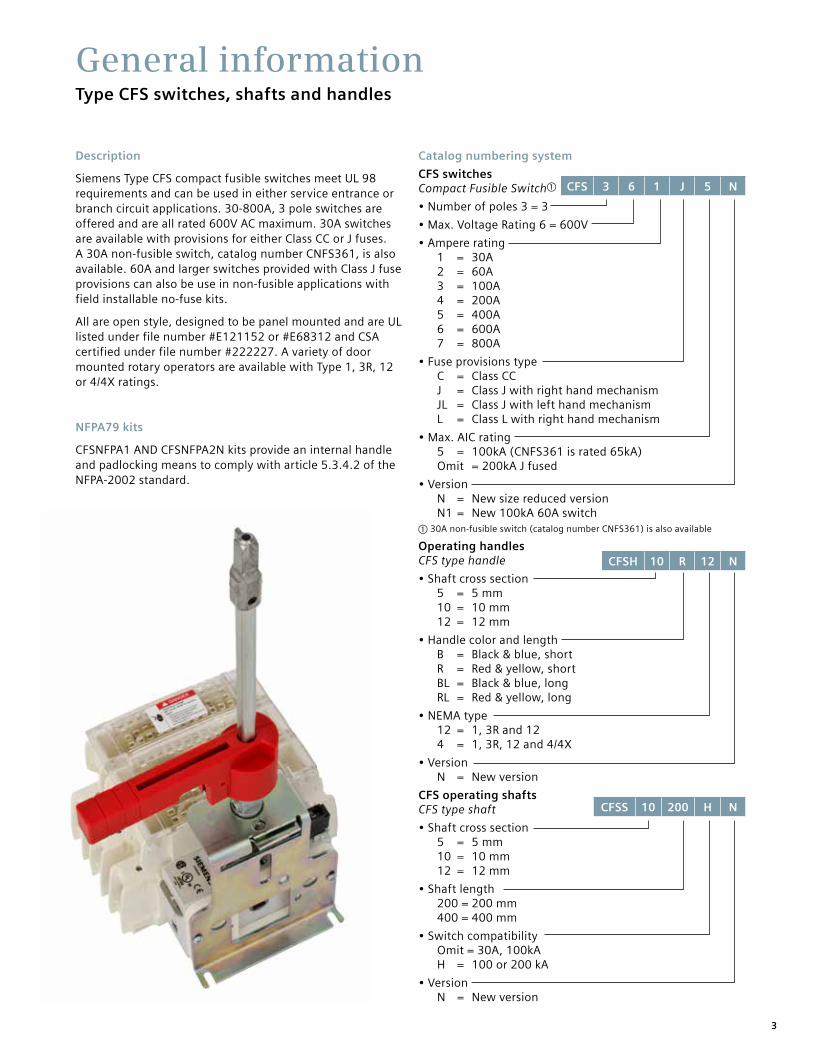
Description
Siemens Type CFS compact fusible switches meet UL 98 requirements and can be used in either service entrance or branch circuit applications. 30-800A, 3 pole switches are offered and are all rated 600V AC maximum. 30A switches are available with provisions for either Class CC or J fuses. A 30A non-fusible switch, catalog number CNFS361, is also available. 60A and larger switches provided with Class J fuse provisions can also be use in non-fusible applications with field installable no-fuse kits.
All are open style, designed to be panel mounted and are UL listed under file number #E121152 or #E68312 and CSA certified under file number #222227. A variety of door mounted rotary operators are available with Type 1, 3R, 12 or 4/4X ratings.
NFPA79 kits
CFSNFPA1 AND CFSNFPA2N kits provide an internal handle and padlocking means to comply with article 5.3.4.2 of the NFPA-2002 standard.
Catalog numbering system
CFS switches Compact Fusible Switcha
• Number of poles 3 = 3
• Max. Voltage Rating 6 = 600V
• Ampere rating 1 = 30A 2 = 60A 3 = 100A 4 = 200A 5 = 400A 6 = 600A 7 = 800A
• Fuse provisions type C = Class CC J = Class J with right hand mechanism JL = Class J with left hand mechanism L = Class L with right hand mechanism
• Max. AIC rating 5 = 100kA (CNFS361 is rated 65kA) Omit = 200kA J fused
• Version N = New size reduced version N1 = New 100kA 60A switcha 30A non-fusible switch (catalog number CNFS361) is also available
Operating handles CFS type handle
• Shaft cross section 5 = 5 mm 10 = 10 mm 12 = 12 mm
• Handle color and length B = Black & blue, short R = Red & yellow, short BL = Black & blue, long RL = Red & yellow, long
• NEMA type 12 = 1, 3R and 12 4 = 1, 3R, 12 and 4/4X
• Version N = New version
CFS operating shafts CFS type shaft
• Shaft cross section 5 = 5 mm 10 = 10 mm 12 = 12 mm
• Shaft length 200 = 200 mm 400 = 400 mm
• Switch compatibility Omit = 30A, 100kA H = 100 or 200 kA
• Version N = New version
CFS 3 6 1 J 5 N
CFSH 10 R 12 N
CFSS 10 200 H N

4
Type CFS compact fusible switchesFeatures and ordering information
Features
30 - 800A ratings
UL Listed under file #E121152 & CSA Certified under file #222227
IEC 60947-3 Certified and CE marked
Door mounted rotary handles with defeatable cover interlock
Meets UL requirements for both main and branch circuit applications
Compact size
100kA with Class CC fuses or up to 200kA with Class J fuses
Load break and horsepower rated
Ordering information
1. Select the panel mounted switch required based on Ampere, HP and AIC requirements. Switches with a right hand mechanism are standard, 30-100A switches with a left hand mechanism are available.
2. Select handle based on environmental rating required.
3. Select operating shaft (200 or 400mm in length). For enclosure depths of 9.0” or less from panel mounting surface to inside of door use 200mm long shafts. For deeper enclosures use 400mm long shafts. 30A 100kA switches can be used in 10” deep enclosures (panel to inside of door) with 200mm shaft and CFSH5N handles.
Note: Be sure to check shaft and handle compatibility with the switch selected by using information provided in the selection tables.
4. Line & load lugs are provided as standard on 30-100A switches. Terminal kits are available for 200-800A switches if needed.
5. Auxiliary contact are available if needed as follows.
A. 30A switch CFS361C5 and non-fusible 30A switch CNFS361 will accept up to (4) aux contacts
B. 30A switch CFS361J5 will accept up to (2) aux contacts without an aux contact holder. If more than (2) aux contacts are required order aux contacts PLUS aux contact holder kit CFSAUXH1. All other switches will accept up to (4) aux contacts.
6. If non-fusible switch is required order a shorting bar for 60-600A switches or catalog number CNFS361 for 30A.
7. 30-100A switches are designed to prevent inadvertent contact with live parts and shields are not required. 200 & 400A switches are not supplied with terminal shields. They are available as field installed kits for both line and load terminals. 400-800A switches are supplied
Switch Shaft Handle Lugs/Accessories
CFS363JN with (2) CFSAUX1NO CFSS10200HN CFSH10BL12N CFSL200
Quick make and break operation
All handles are padlockable with up to (3) padlocks with 5/16” hasps in the OFF position
Catalog number CFS361C5, CFS361J5 & CNFS361 can be DIN-rail mounted and can be either front or side operated with standard rotary handles.
All CFS part numbers ending in N can be either front or side operated with standard rotary handles.
Handles are available in Type 1, 3R, 4/4X & 12 ratings
NFPA 79 field installed kits are available
30-400A, 200kA switches are provided with quick connect terminal provisions for voltage sensing or for 10A max. control circuits
5
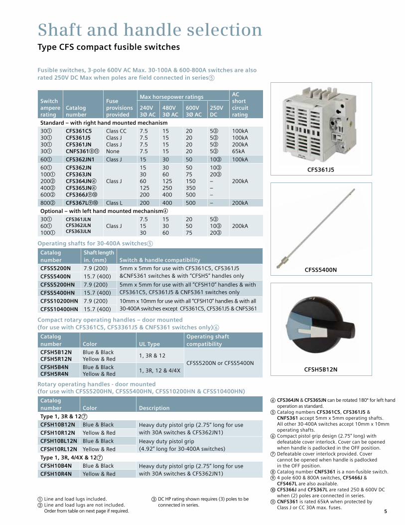
Shaft and handle selectionType CFS compact fusible switches
Fusible switches, 3-pole 600V AC Max. 30-100A & 600-800A switches are also rated 250V DC Max when poles are field connected in seriese
Switch ampere rating
Catalog number
Fuse provisions provided
Max horsepower ratings AC short circuit rating
240V 3Ø AC
480V 3Ø AC
600V 3Ø AC
250V DC
Standard – with right hand mounted mechanism
30a
30a
30a
30a
CFS361C5CFS361J5CFS361JNCNFS361hk
Class CCClass JClass JNone
7.57.57.57.5
15151515
20202020
5c
5c
5c
5c
100kA100kA200kA65kA
60a CFS362JN1 Class J 15 30 50 10c 100kA
60a
100a
200b
400b
600b
CFS362JNCFS363JNCFS364JNd
CFS365JNd
CFS366Jij
Class J
153060125200
3060125250400
5075150350500
10c
20c
–––
200kA
800b CFS367Lij Class L 200 400 500 – 200kA
Optional – with left hand mounted mechanismd
30a
60a
100a
CFS361JLNCFS362JLNCFS363JLN
Class J7.51530
153060
205075
5c
10c
20c200kA
Operating shafts for 30-400A switchese
Catalog number
Shaft length in. (mm) Switch & handle compatibility
CFSS5200N 7.9 (200) 5mm x 5mm for use with CFS361C5, CFS361J5 &CNFS361 switches & with “CFSH5” handles onlyCFSS5400N 15.7 (400)
CFSS5200HN 7.9 (200) 5mm x 5mm for use with all ”CFSH10” handles & with CFS361C5, CFS361J5 & CNFS361 switches onlyCFSS5400HN 15.7 (400)
CFSS10200HN 7.9 (200) 10mm x 10mm for use with all “CFSH10” handles & with all 30-400A switches except CFS361C5, CFS361J5 & CNFS361CFSS10400HN 15.7 (400)
Compact rotary operating handles – door mounted (for use with CFS361C5, CFS3361J5 & CNFS361 switches only)f
Catalog number Color UL Type
Operating shaft compatibility
CFSH5B12N CFSH5R12N
Blue & Black Yellow & Red
1, 3R & 12CFSS5200N or CFSS5400N
CFSH5B4NCFSH5R4N
Blue & Black Yellow & Red
1, 3R, 12 & 4/4X
Rotary operating handles - door mounted (for use with CFSS5200HN, CFSS5400HN, CFSS10200HN & CFSS10400HN)
Catalog number Color Description
Type 1, 3R & 12g
CFSH10B12N Blue & Black Heavy duty pistol grip (2.75” long for use with 30A switches & CFS362JN1)CFSH10R12N Yellow & Red
CFSH10BL12N Blue & Black Heavy duty pistol grip (4.92” long for 30-400A switches)CFSH10RL12N Yellow & Red
Type 1, 3R, 4/4X & 12g
CFSH10B4N Blue & Black Heavy duty pistol grip (2.75” long for use with 30A switches & CFS362JN1)CFSH10R4N Yellow & Red
a Line and load lugs included. b Line and load lugs are not included. Order from table on next page if required.
CFS361J5
CFSS5400N
CFSH5B12N
c DC HP rating shown requires (3) poles to be connected in series.
d CFS364JN & CFS365JN can be rotated 180º for left hand operation as standard. e Catalog numbers CFS361C5, CFS361J5 & CNFS361 accept 5mm x 5mm operating shafts. All other 30-400A switches accept 10mm x 10mm operating shafts. f Compact pistol grip design (2.75” long) with defeatable cover interlock. Cover can be opened when handle is padlocked in the OFF position. g Defeatable cover interlock provided. Cover cannot be opened when handle is padlocked in the OFF position. h Catalog number CNFS361 is a non-fusible switch. i 4 pole 600 & 800A switches, CFS466J & CFS467L are also available. j CFS366J and CFS367L are rated 250 & 600V DC when (2) poles are connected in series. k CNFS361 is rated 65kA when protected by Class J or CC 30A max. fuses.

6
600 & 800A rotary operating handles - door mounted (8.27” long)g
Catalog number Color UL Type
CFSH12BL12 Blue & Black 1, 3R & 12
CFSH12RL12 Yellow & Red 1, 3R & 12
CFSH12BL4 Blue & Black 1, 3R, 12 & 4/4X
CFSH12RL4 Yellow & Red 1, 3R, 12 & 4/4X
600 & 800A operating shafts (cross section 12 x 12 mm)
Catalog number
Shaft length in. (mm)
Enclosure depth (switch mounting surface to door OD)
CFSS12200H 12.59 (320) 10.43 – 16.68 in.
CFSS12400H 15.75 (400) 10.43 – 19.84 in.
Type CFS fusible switch accessories
Catalog number Description
Terminalsa
CFSL200 200A lug kit (6 lugs per kit) (1)#6-3/0
CFSL400N 400A lug kit (6 lugs per kit) (1)#2-600kcmil (for CFS365JN only)
CFSL400 600-800A lug kit (6 lugs per kit) (2)#2-600kcmil
Shorting bars (no fuse kits)
CFSSB60 60A shorting bar kit (3 links per kit)
CFSSB100 100A shorting bar kit (3 links per kit)
CFSSB200 200A shorting bar kit (3 links per kit)
CFSSB400 400A shorting bar kit (3 links per kit)
CFSSB680 600 & 800A shorting bar kit (1 link per kit)
Auxiliary contacts (NEMA ratings AC A600 DC N600)
CFSAUXH1b Aux contact holder (CFS361J5, CFS361C5 & CNFS361)
CFSAUX1NO Aux contact 1 NO (30-800A Sws)
CFSAUX1NC Aux contact 1 NC (30-800A Sws)
CFS11AUX 1NO, 1NC aux contact kit (side mount for 200kA switches)
CFS22AUX 2NO, 2NC aux contact kit (side mount for 200kA switches)
Terminal shrouds (line or load)
CFSTS200Nh 200A shroud kit (line or load 3-pole kit)
CFSTS400Nh 400A shroud kit (line or load 3-pole kit for CFS365JN only)
CFSTS680f 600/800A 3-pole shroud kit
CFSTS6804f 600/800A 4-pole shroud kit
30A compact switch kits
CFSPLK Shaft padlocking kit for 30A compact switch when door is openc
CFSH5CDM Direct mount handle kit for CFS361C5 & CNFS361
CFSH5JDM Direct mount handle kit for CFS361J5
NFPA 79 kits (if auxiliary contacts are needed, see table on page 7) Kits provide an operating shaft suitable for use with all heavy duty handles (not for use with CFSH5 handles). Kits also provide an internal operating handle and an internal OFF padlocking provision.
CFSNFPA1d For use with CFS361C5, CFS361J5 & CNFS361
CFSNFPA2Ne For use with CFS361JN, CFS361CN, CFS362JN1, CFS362JN, CFS363JN & CFS364JN
Selection and accessoriesType CFS compact fusible switches
a Supplied as standard on 30-100A switches b CFS361C5 and CNFS361 will accept (4) aux contacts without an aux contact holder. CFS361J5 will accept (2) aux contacts without an aux contact holder. c Supplied as standard on all but 30A, 65kA & 100kA compact switches. d 12.6 in. (320 mm) long operating shaft included e 12.7 in. (323 mm) long operating shaft included
CFSL200 & 400
CFSAUX1NC
CFSSB100 - CFSSB400
f Line side terminal shrouds supplied with switch g Defeatable cover interlock included. Cover cannot be opened when the handle is padlocked in the OFF position. h Neither line or load terminal shrouds are supplied as standard with new style 200 & 400A switches.

7
Dimensions and technical characteristicsType CFS compact fusible switches
UL & CSA technical characteristics and panel space requirements
Catalog number Amps
Fuse Class
AC short circuit rating
Electrical endurance
Mechanical endurance
Panel space requirements - in. (mm)
Height Width Deptha
CFS361C5 30 CC 100kA 6000 10000 4.56 (116) 3.78 (96) 6.00 (152)
CFS361J5 30 J 100kA 6000 10000 4.56 (116) 4.15 (105) 6.00 (152)
CFS361JN 30 J 200kA 6000 10000 5.35 (136) 5.89 (150) 6.00 (152)
CFS361JLN 30 J 200kA 6000 10000 5.35 (136) 5.89 (150) 6.00 (152)
CNFS361 30 None 65kAb 6000 10000 4.56 (116) 3.78 (96) 6.00 (152)
CFS362JN1 60 J 100kA 6000 10000 5.35 (136) 5.89 (150) 6.00 (152)
CFS362JN 60 J 200kA 6000 10000 7.32 (186) 5.89 (150) 6.00 (152)
CFS362JLN 60 J 200kA 6000 10000 7.32 (186) 5.89 (150) 6.00 (152)
CFS363JN 100 J 200kA 6000 10000 7.32 (186) 5.89 (150) 6.00 (152)
CFS363JLN 100 J 200kA 6000 10000 7.32 (186) 5.89 (150) 6.00 (152)
CFS364JN 200 J 200kA 6000 8000 11.46 (291) 7.72 (196) 6.00 (152)
CFS365JN 400 J 200kA 1000 6000 15.35 (390) 10.19 (259) 8.00 (203)
CFS366J 600 J 200kA 1000 5000 11.81 (300) 14.33 (364) 11 (280)
CFS466J 600 J 200kA 1000 5000 11.81 (300) 18.03 (458) 11 (280)
CFS367L 800 L 200kA 500 3500 11.81 (300) 14.33 (364) 11 (280)
CFS467L 800 L 200kA 500 3500 11.81 (300) 18.03 (458) 11 (280)
Wire ranges line & load lugs
Switch Amperage Rating
"UL approved wire size (75º C)"
CFS361J5 30 (1)#14-10
CFS361C5 30 (1)#14-10
CNFS361 30 (1)#14-10
CFS361JN 30 (1)#14-6
CFS362JN1 60 (1)#14-6
CFS362JN 60 (1)#12-1
CFS363JN 100 (1)#12-1
CFS364JN 200 (1)#3/0
CFS365JN 400 (1)600MCM
CFS366J 600 (2)350 MCM
CFS367L 800 (2)600 MCM
Auxiliary contact capability when an NFPA79 kit is used
Switch NFPA79 kit Aux contacts that can be installed
CNFS361
CFSNFPA1(2) Total, CFSAUX1NO or CFSAUX1NCCFS361C5
CFS361J5 (1) CFSAUX1NO or (1) CFSAUX1NC
CFS361JN
CFSNFPA2N (2) Total, CFSAUX1NO or CFSAUX1NCc
CFS362JN1
CFS362JN
CFS363JN
CFS364JN
CFS365JN CFSNFPA3N (2) Total, CFSAUX1NO or CFSAUX1NCc
a Minimum dimensions from mounting surface to inside of cover. Dimensions shown can be decreased if aux contacts are not required. b CNFS361 is rated 65kA when protected by 30A max. Class J or CC fuses. c For additional auxiliary contacts use side mounted CFS11AUX or CFS22AUX.

8
DimensionsType CFS compact fusible UL98 switches
CFS361C5CNFS361
CFS361J5
Dimensions - 30A, 100kA (65kA for CNFS361) switches
CFS361C5CFS361J5CNFS361
Recommended minimum enclosure dimensions
Note: CNFS361, CFS361C5 and CFS361J5 can be DIN-rail mounted
Dimensions - in. (mm)
Catalog no. A B C H1 J J1 K K1 Y
CFS361C5 3.78 (96) 4.56 (116) 3.28 (84) 5.19 (132) 1.47 (37) 0.59 (15) 3.13 (80) 1.00 (25) 1.12 (28)
CFS361J5 4.13 (105) 4.56 (116) 3.89 (99) – 1.47 (37) 0.59 (15) 3.30 (84) 1.00 (25) 1.12 (28)
Dimensions - in. (mm)
Catalog no. A B C H J J1 K K1 ØL
CFS361C56.0 (152) 8.00 (203) 6.0 (152) 3.5 (89) 1.47 (37) 0.59 (15) 3.13 (80) 1.00 (25) 0.21 (5)
CNFS361

9
DimensionsType CFS compact fusible UL98 switches
CFS361JNCFS362JN1CFS362JNCFS363JN
Dimensions - 30-100A, 100kA & 200kA switches
Dimensions - 200A, 200kA switch
CFS364JN
Dimensions - in. (mm)
Catalog no. A B C J J1 K K1 L Y
CFS361JNa5.88 (149.5) 5.35 (136) 4.84 (123) 1.41 (36) 2.12 (54) 4.25 (108) 1.12 (54) 0.25 (6.5) 1.43 (36.5)
CFS362JN1a
Dimensions - in. (mm)
Catalog no. A B C J J1 K K1 ØL Y
C
Y
B
7.83199
1 : 9.13232
2 :
1.1429
0.4010,3
Y
X
J
J
J1
K1
K
A
5126,5
L
0.4010,3
10.86276
C
Y
B
1.1429
Y
X
J
J1
J1M 8
K1
K
A
5126,5
Ø L
1.42 in / 36 mm
1.69 in / 43 mm

10
DimensionsType CFS compact fusible UL98 switches
CFS361JNCFS362JN1CFS362JNCFS363JN
Recommended minimum enclosure dimensions for 30-100A, 100kA & 200kA switches
Dimensions - in. (mm)
Catalog no. A B C J J1 K K1 L
CFS361JN10 (254) 10 (254) 6 (153) 1.41 (36) 2.12 (54) 4.25 (106) 1.12 (54) 0.25 (6.5)
CFS362JN1
A C
J J1 0.83 in / 21mm
K1
L
Y
X
L = X - 1.71 inL = X - 43,5 mm
L
X
min. 0.78 in / 20 mmmax. 1.18 in / 30 mm
0.76 ±.079 in
19,5 ±2 mm
B K
11
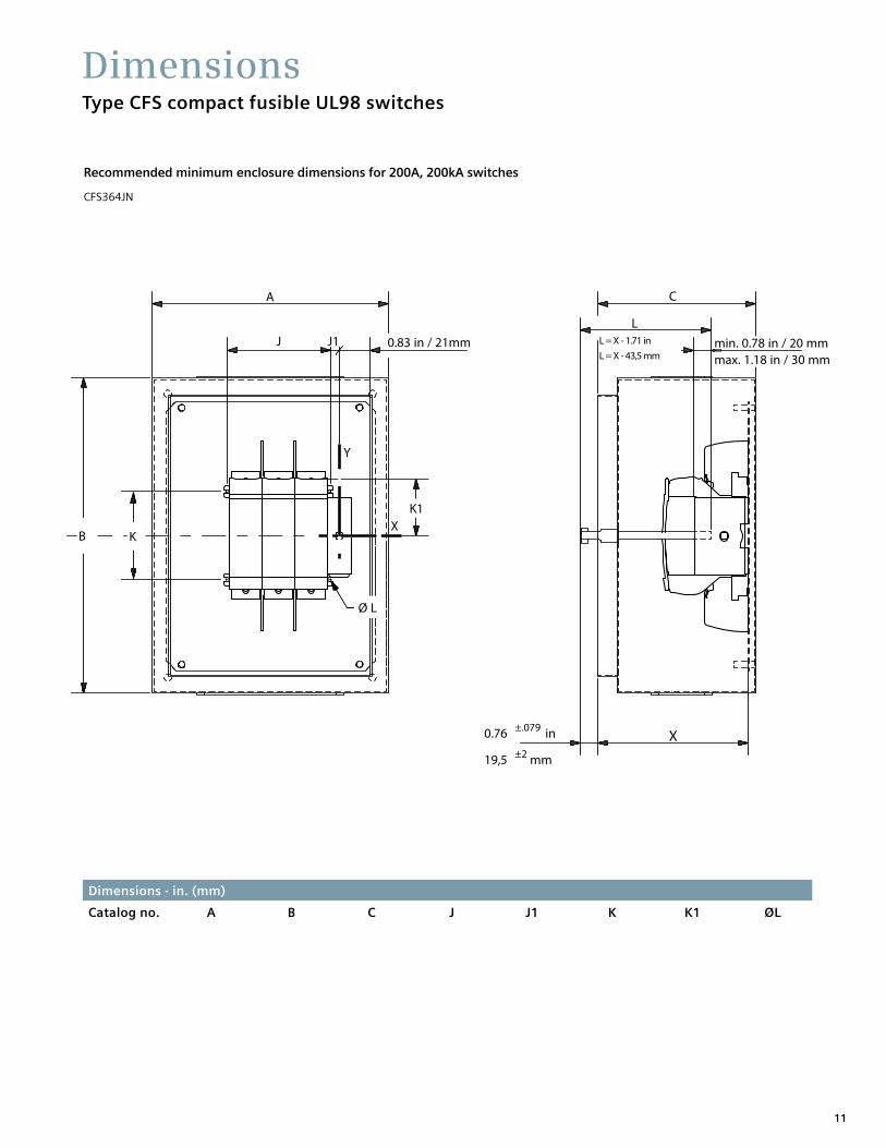
DimensionsType CFS compact fusible UL98 switches
CFS364JN
Recommended minimum enclosure dimensions for 200A, 200kA switches
Dimensions - in. (mm)
Catalog no. A B C J J1 K K1 ØL
A C
J 0.83 in / 21mm
K1
Ø L
Y
X
L = X - 1.71 inL = X - 43,5 mm
L
X
min. 0.78 in / 20 mmmax. 1.18 in / 30 mm
0.76 ±.079 in
19,5 ±2 mm
B K
J1
12
Dimensions - in. (mm)
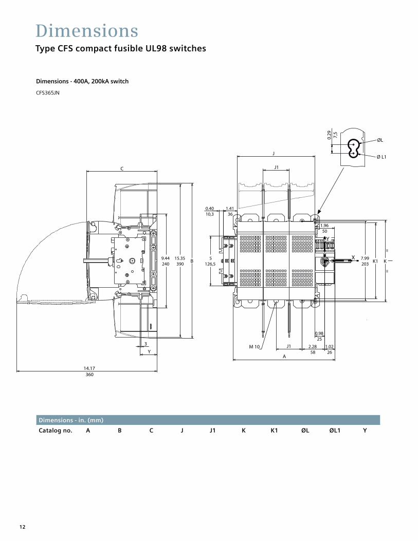
Catalog no. A B C J J1 K K1 ØL ØL1 Y
DimensionsType CFS compact fusible UL98 switches
CFS365JN
Dimensions - 400A, 200kA switch
0.4010,3
14.17360
C
Y
3
1.4136
1.9650
Y
X
J
J1
J1M 10
K1 K
==
A
5126,5
15.35 390
9.44240
7.99203
1.0226
2.2858
0.9825
B
0.29 7,5
ØL
Ø L1

13
DimensionsType CFS compact fusible UL98 switches
Recommended minimum enclosure dimensions
Front operationCommande frontaleMando frontal
A C
J 5.12 in / 130mm
Y
X
L = X - 2.97 inL = X - 75,5 mm
L
X 0.76 ±.079 in
19,5 ±2 mm
B K
J1
0.29 7,5
ØL
Ø L1
min. 0.78 in / 20 mmmax. 1.18 in / 30 mm
K1
K2
==
Front operationCommande frontaleMando frontal
A C
J 5.12 in / 130mm
Y
X
L = X - 2.97 inL = X - 75,5 mm
L
X 0.76 ±.079 in
19,5 ±2 mm
B K
J1
0.29 7,5
ØL
Ø L1
min. 0.78 in / 20 mmmax. 1.18 in / 30 mm
K1
K2
==
Dimensions - in. (mm)
Catalog no. A B C J J1 K K1 K2 ØL ØL1
Front operationCommande frontaleMando frontal
A C
J 5.12 in / 130mm
Y
X
L = X - 2.97 inL = X - 75,5 mm
L
X 0.76 ±.079 in
19,5 ±2 mm
B K
J1
0.29 7,5
ØL
Ø L1
min. 0.78 in / 20 mmmax. 1.18 in / 30 mm
K1
K2
==

14
DimensionsType CFS compact fusible UL98 switches
CFS366J CFS466J CFS367L CFS467L
Dimensions - 600A & 800A, 200kA switches
Recommended minimum enclosure dimensions
CFS366J CFS466J CFS367L CFS467L
Dimensions - in. (mm)
Catalog no. A C C1 H H1 H3 J J1
Dimensions - in. (mm)
Catalog no. A B C H J J1 K K1
CFS366J CFS367L 36 (914.5) 48 (1219) 12 (305) 23.13 (587.5) 11.18 (284) 1.34 (34) 9.84 (250) 4.05 (103)
C
11.81300
9.84250
10.23260
10.15258
8.42214
J
H3
J1 J1
1.34 34
.4311
5126,5
.4010,3
1.1429
.359
C1 A
H1
1.8146
.277
.2778.26
210
.277
H
3.5490
2.3259
251
Ø.5113
.7820
Y
X
A C
B
H
K
J J1
K1
Y
X
X
LL = X - 4.09 inL = X - 104 mm
0.35 in9 mm
0.90 in23 mm
X min. 10.43 in / 265 mm
Only for S type
min. 1.57 in / 40 mmmax. 5.25 in / 133mm

15
Heavy duty handles:
4.93 (125.1)
8.27 (209.8)
3.07 1.58 3.07
Door drilling - typical
1.77 (44.8) for CFSH10_ _ _ & 2.25 (57.1) for CFSH12_ _ _
DimensionsType CFS compact fusible UL98 switches
Compact handles:CFS5B12NCFS5R12NCFS5B4NCFS5R4N
CFSH10B12N CFSH10R12N CFSH10B4N
CFSH10BL12N CFSH10RL12N CFSH10BL4N
CFSH12BL12 CFSH12RL12 CFSH12BL4
Dimensions - handles and door drillings Dimensions shown in inches and millimeters ( ).
3.48 (88.4)
2.12 (53.7)
2.71 (68.9)
1.36 (34.6)
1.40 (35.6) 1.89
(48.0)
1.58 (40)
1.10
Door drilling

Siemens Industry, Inc.5400 Triangle ParkwayNorcross, GA 30092
Printed in USA | www.usa.siemens.com/switchesOrder no.: SSBR-03000-1013 | © 2013 Siemens Industry, Inc.
The information provided in this brochure contains merely general descriptions or characteristics of performance which in case of actual use do not always apply as described or which may change as a result of further development of the products. An obligation to provide the respective characteristics shall only exist if expressly agreed in the terms of contract.
All product designations may be trademarks or product names of Siemens AG or supplier companies whose use by third parties for their own purposes could violate the rights of the owners.