tym10002000 slidegateoperatormanual r7 - tymetal 1000/2000 slide gate operator installation guide -...
TRANSCRIPT
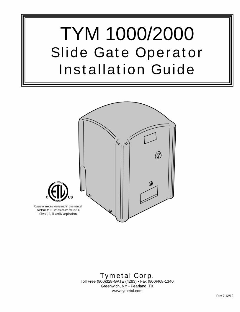
TYM 1000/2000Slide Gate OperatorInstallation Guide
Operator models contained in this manualconform to UL325 standard for use in
Class I, II, III, and IV applications
Tymetal Corp.Toll Free (800)328-GATE (4283) • Fax (800)468-1340
Greenwich, NY • Pearland, TXwww.tymetal.com
Rev 7 12/12

Table of ContentsPre-installation Information . . . . . . . . . . . . . . . . . . . . . . . . . . . . . . . . . . 1
Before You Begin... . . . . . . . . . . . . . . . . . . . . . . . . . . . . . . . . . . . . . . 1Always Check the Gate’s Action . . . . . . . . . . . . . . . . . . . . . . . . . . . .1Gate Operator Classifi cations . . . . . . . . . . . . . . . . . . . . . . . . . . . . . .1Approved Obstruction Detection Devices . . . . . . . . . . . . . . . . . . . . .1
Safety Information and Warnings . . . . . . . . . . . . . . . . . . . . . . . . . . . . . 1Regulatory Warnings. . . . . . . . . . . . . . . . . . . . . . . . . . . . . . . . . . . . . 1
Wiring Specifi cations . . . . . . . . . . . . . . . . . . . . . . . . . . . . . . . . . . . . . . .2AC Power Wiring. . . . . . . . . . . . . . . . . . . . . . . . . . . . . . . . . . . . . . . .2DC Control and Accessory Wiring. . . . . . . . . . . . . . . . . . . . . . . . . . . 2
Mounting Pad Installation. . . . . . . . . . . . . . . . . . . . . . . . . . . . . . . . . . . . 3Gate Preparation. . . . . . . . . . . . . . . . . . . . . . . . . . . . . . . . . . . . . . . . 3
Gate Bracket and Chain Assembly . . . . . . . . . . . . . . . . . . . . . . . . . . . .5
Operator Preparation . . . . . . . . . . . . . . . . . . . . . . . . . . . . . . . . . . . . . . .6Vent Plug Installation. . . . . . . . . . . . . . . . . . . . . . . . . . . . . . . . . . . . .6
Operator Setup . . . . . . . . . . . . . . . . . . . . . . . . . . . . . . . . . . . . . . . . . . . .6Controller Access . . . . . . . . . . . . . . . . . . . . . . . . . . . . . . . . . . . . . . .6AC Power Connection. . . . . . . . . . . . . . . . . . . . . . . . . . . . . . . . . . . . 6Earth Ground. . . . . . . . . . . . . . . . . . . . . . . . . . . . . . . . . . . . . . . . . . . 6Limit Nuts Rough Adjustment . . . . . . . . . . . . . . . . . . . . . . . . . . . . . . 7Limit Nuts Fine Adjustment . . . . . . . . . . . . . . . . . . . . . . . . . . . . . . . .7
Controller Features . . . . . . . . . . . . . . . . . . . . . . . . . . . . . . . . . . . . . . . . . 8
Indicator Descriptions. . . . . . . . . . . . . . . . . . . . . . . . . . . . . . . . . . . . . . . 9
Terminal Descriptions. . . . . . . . . . . . . . . . . . . . . . . . . . . . . . . . . . . . . . 10
Operator Accessory Connections . . . . . . . . . . . . . . . . . . . . . . . . . . . . 11Basic Controller Programming . . . . . . . . . . . . . . . . . . . . . . . . . . . . . . 12
Programming Overview. . . . . . . . . . . . . . . . . . . . . . . . . . . . . . . . . . 12Entering Programming Mode . . . . . . . . . . . . . . . . . . . . . . . . . . . . . 12Exiting Programming Mode. . . . . . . . . . . . . . . . . . . . . . . . . . . . . . . 12Programming Keystrokes . . . . . . . . . . . . . . . . . . . . . . . . . . . . . . . . 12Left or Right Hand Operation . . . . . . . . . . . . . . . . . . . . . . . . . . . . . 12Dual Gate Enable . . . . . . . . . . . . . . . . . . . . . . . . . . . . . . . . . . . . . . 12Auto Close Timer. . . . . . . . . . . . . . . . . . . . . . . . . . . . . . . . . . . . . . . 12Run Alarm and Pre-start Alarm . . . . . . . . . . . . . . . . . . . . . . . . . . . . 13Maximum Open Direction Current Setting. . . . . . . . . . . . . . . . . . . . 13Maximum Close Direction Current Setting . . . . . . . . . . . . . . . . . . . 13
Advanced Controller Programming. . . . . . . . . . . . . . . . . . . . . . . . . . .14Entering Advanced Programming Mode . . . . . . . . . . . . . . . . . . . . .14Maximum Run Time . . . . . . . . . . . . . . . . . . . . . . . . . . . . . . . . . . . .14Single Button Input Setup . . . . . . . . . . . . . . . . . . . . . . . . . . . . . . . .14Stagger Mode (Rarely used in slide gate installations) . . . . . . . . . . 14Stagger Delay Time (Rarely used in slide gate installations) . . . . .15Auxiliary Relay Mode. . . . . . . . . . . . . . . . . . . . . . . . . . . . . . . . . . . .15Reverse Delay Time . . . . . . . . . . . . . . . . . . . . . . . . . . . . . . . . . . . .15Reset Cycle Count . . . . . . . . . . . . . . . . . . . . . . . . . . . . . . . . . . . . . 16Maintenance Alert Trigger . . . . . . . . . . . . . . . . . . . . . . . . . . . . . . . . 16Mid-travel Stop Position . . . . . . . . . . . . . . . . . . . . . . . . . . . . . . . . . 16Motor Type Selection. . . . . . . . . . . . . . . . . . . . . . . . . . . . . . . . . . . .16Radio Enable. . . . . . . . . . . . . . . . . . . . . . . . . . . . . . . . . . . . . . . . . . 17Antenna Installation. . . . . . . . . . . . . . . . . . . . . . . . . . . . . . . . . . . . .17Radio Transmitter Learn . . . . . . . . . . . . . . . . . . . . . . . . . . . . . . . . . 17Radio Transmitter Delete. . . . . . . . . . . . . . . . . . . . . . . . . . . . . . . . .17MGT Obstacle Transmitter Learn . . . . . . . . . . . . . . . . . . . . . . . . . . 17MGT Obstacle Transmitter Delete. . . . . . . . . . . . . . . . . . . . . . . . . . 17Reset Controller to Factory Defaults . . . . . . . . . . . . . . . . . . . . . . . . 17
APeX v 1.4 Quick Programming Guide . . . . . . . . . . . . . . . . . . . . . . . .18Loop Layout Illustration . . . . . . . . . . . . . . . . . . . . . . . . . . . . . . . . . . . .20
Loop Detector Operating Instructions. . . . . . . . . . . . . . . . . . . . . . . . . 21
Using Gate Reversing Edge Transmitters. . . . . . . . . . . . . . . . . . . . . . 23
Reversing Edge Layout Illustration . . . . . . . . . . . . . . . . . . . . . . . . . . .24Photoeye Installation Illustration . . . . . . . . . . . . . . . . . . . . . . . . . . . . . 25
Picket Gate Installation . . . . . . . . . . . . . . . . . . . . . . . . . . . . . . . . . . . . . 26
Dual Gate Installations . . . . . . . . . . . . . . . . . . . . . . . . . . . . . . . . . . . . . 27
Gate Operation. . . . . . . . . . . . . . . . . . . . . . . . . . . . . . . . . . . . . . . . . . . . 28Open Button . . . . . . . . . . . . . . . . . . . . . . . . . . . . . . . . . . . . . . . . . . 28Close Button . . . . . . . . . . . . . . . . . . . . . . . . . . . . . . . . . . . . . . . . . . 28Stop Button . . . . . . . . . . . . . . . . . . . . . . . . . . . . . . . . . . . . . . . . . . .28Single Input . . . . . . . . . . . . . . . . . . . . . . . . . . . . . . . . . . . . . . . . . . . 28Fire Department Input . . . . . . . . . . . . . . . . . . . . . . . . . . . . . . . . . . . 28Fire Department Access . . . . . . . . . . . . . . . . . . . . . . . . . . . . . . . . . 28Open Input. . . . . . . . . . . . . . . . . . . . . . . . . . . . . . . . . . . . . . . . . . . .28Open Obstruction . . . . . . . . . . . . . . . . . . . . . . . . . . . . . . . . . . . . . . 28Close Obstruction . . . . . . . . . . . . . . . . . . . . . . . . . . . . . . . . . . . . . . 28Reverse Input . . . . . . . . . . . . . . . . . . . . . . . . . . . . . . . . . . . . . . . . . 28Open Loop. . . . . . . . . . . . . . . . . . . . . . . . . . . . . . . . . . . . . . . . . . . .28Reverse Loop . . . . . . . . . . . . . . . . . . . . . . . . . . . . . . . . . . . . . . . . . 28Shadow/reset Loop . . . . . . . . . . . . . . . . . . . . . . . . . . . . . . . . . . . . . 28
Operation Indications . . . . . . . . . . . . . . . . . . . . . . . . . . . . . . . . . . . . . . 29Power-up Display . . . . . . . . . . . . . . . . . . . . . . . . . . . . . . . . . . . . . . 29Idle Condition . . . . . . . . . . . . . . . . . . . . . . . . . . . . . . . . . . . . . . . . . 29Last Gate Position/Condition. . . . . . . . . . . . . . . . . . . . . . . . . . . . . . 29Pre-start Delay . . . . . . . . . . . . . . . . . . . . . . . . . . . . . . . . . . . . . . . .29Reverse Delay. . . . . . . . . . . . . . . . . . . . . . . . . . . . . . . . . . . . . . . . .29Run Timer . . . . . . . . . . . . . . . . . . . . . . . . . . . . . . . . . . . . . . . . . . . .29
Error Indications . . . . . . . . . . . . . . . . . . . . . . . . . . . . . . . . . . . . . . . . . . 29Entrapment . . . . . . . . . . . . . . . . . . . . . . . . . . . . . . . . . . . . . . . . . . .29COMM LINK Connection Failure. . . . . . . . . . . . . . . . . . . . . . . . . . . 29MGT Obstacle Transmitter Trouble . . . . . . . . . . . . . . . . . . . . . . . . .29Maximum Run Time Exceeded . . . . . . . . . . . . . . . . . . . . . . . . . . . . 29
Troubleshooting . . . . . . . . . . . . . . . . . . . . . . . . . . . . . . . . . . . . . . . . . . 30Contacting Technical Support . . . . . . . . . . . . . . . . . . . . . . . . . . . . .30Operator fails to start. . . . . . . . . . . . . . . . . . . . . . . . . . . . . . . . . . . .30Motor operates, but gate does not move. . . . . . . . . . . . . . . . . . . . .30Motor sounds like it is working harder than normal . . . . . . . . . . . . . 30Limit switch getting out of time . . . . . . . . . . . . . . . . . . . . . . . . . . . .30Gate stopping part way open or closed(but no visible obstruction) . . . . . . . . . . . . . . . . . . . . . . . . . . . . . . . 30Gate staying open with automatic system. . . . . . . . . . . . . . . . . . . . 30How to Order Replacement Parts . . . . . . . . . . . . . . . . . . . . . . . . . .30
Safety Information . . . . . . . . . . . . . . . . . . . . . . . . . . . . . . . . . . . . . . . . . 31Manual Disconnect . . . . . . . . . . . . . . . . . . . . . . . . . . . . . . . . . . . . . . . .32
Gate Obstruction Sensing Information . . . . . . . . . . . . . . . . . . . . . . . .32
TYM 1000/2000 Exploded View and Parts List . . . . . . . . . . . . . . . . . . 33
Preventative Maintenance . . . . . . . . . . . . . . . . . . . . . . . . . . . . . . . . . . 35General . . . . . . . . . . . . . . . . . . . . . . . . . . . . . . . . . . . . . . . . . . . . . . 35Lubrication. . . . . . . . . . . . . . . . . . . . . . . . . . . . . . . . . . . . . . . . . . . .356-Month Preventative Maintenance. . . . . . . . . . . . . . . . . . . . . . . . .35
FCC Notice . . . . . . . . . . . . . . . . . . . . . . . . . . . . . . . . . . . . . . . . . . . . . . .35
Gate Operator Installation Checklist . . . . . . . . . . . . . . . . . . . . . . . . . . 36
TYMETAL
TYM 1000/2000 Slide Gate Operator Installation Guide - 1 - Rev 7 12/12
Pre-installation Information
Before You Begin...Before unpacking, inspect the carton for exterior damage. If you fi nd damage, advise the delivery carrier of a potential claim. Inspect yourpackage carefully. You can check your accessory box parts with theenclosed packing slip for your convenience. Claims for shortages will behonored for only 30 days from the date of shipment.
Before installing the operator, read this manual completely to ensure allrequirements for proper installation are present. Verify that the voltage to beused matches the voltage of the operator.
If you have any questions about the requirements for proper installationof this gate operator contact technical support at 800-328-4283
Always Check the Gate’s ActionIt’s very important before installing the gate operator tomake sure the gate’s slides free and level throughoutthe entire opening distance. If the gate does notseem to operate properly, it may affect the operatorperformance or greatly shorten the life of the unit. Thegate should also be designed so that airfl ow is ample to prevent wind resistance and drag.
Gate Operator Classifi cationsAll gate operators can be divided into one of four different classifi cations, depending on their design and usage. Install this gate operator onlywhen the operator is appropriate for the construction and usage classas defi ned below:
• Class I Residential Vehicular Gate OperatorA vehicular gate operator intended for use in a home or for one tofour single family dwellings with a common garage or parking areaassociated with these dwellings.
• Class II Commercial / General Access Vehicular GateOperatorA vehicular gate operator intended for use in a commercial location orbuilding such as a multi-family housing unit of fi ve or more single family units, hotel, retail store or other building servicing the general public.
• Class III Industrial / Limited Access Vehicular GateOperatorA vehicular gate operator intended for use in an industrial location orbuilding such as a factory or loading dock area or other location notintended to service the general public.
• Class IV Restricted Access Vehicular Gate OperatorA vehicular gate operator intended for use in a guarded industriallocation or building such as an airport security area or other restrictedaccess locationsnotservicing the generalpublic, in which unauthorizedaccess is prevented via supervision by security personnel.
Approved Obstruction Detection DevicesThe following contact or non-contact obstruction detectiondevices have been approved for use with this slide gateoperator as part of a UL325 compliant installation:
• Contact EdgesMiller Edge Models MGO20, MGR20, MGS20, ME120
• PhotoeyesMMTC Model IR-55 (165’ range)MMTC Model E3K (28’ range)
Safety Information and Warnings
Regulatory WarningsRead the following before beginning to install this slide gateoperator:
WARNINGThis type of warning note is used toindicate possible mechanical hazardsthat may cause serious injuries or death.
CAUTIONThis type of warning note is used toindicate the possibility of damage to thegate or gate operator.
WARNINGThis type of warning note is used toindicate possible electrical shock hazardsthat may cause serious injuries or death.
THE FOLLOWING FORMATS ARE USED FOR SAFETY NOTESIN THESE INSTRUCTIONS.
IMPORTANT INSTALLATIONSAFETY INSTRUCTIONS
WARNINGTO REDUCE THE RISK OF SEVERE
INJURY OR DEATH TO PERSONS,
REVIEW THESE INSTALLATION SAFETY
STEPS BEFORE PROCEEDING
1. READ AND FOLLOW ALL INSTALLATION INSTRUCTIONS.
2. Read the yellow “Safety Instructions” brochure enclosed with the packetof information. If any pages are missing or are unreadable, or you do nothave the safety instructions, please call Tymetal Corp. at 1-800-328-4283to request additional copies.
3. ALL ELECTRICAL CONNECTIONS TO THE POWER SUPPLY MUSTBE MADE BY A LICENSED ELECTRICIAN AND MUST OBSERVE ALLNATIONAL AND LOCAL ELECTRICAL CODES.
4. A separate power-disconnect switch should be located near the operatorso that primary power can be turned off when necessary.
5. Install the enclosed warning signs on both sides of the gate. A minimumof two (2) WARNING SIGNS shall be installed, one on each side of thegate where easily visible.
6. Never reach between, through or around the fence to operate the gate.
7. Never connect a button station within reach of the gate or on the side ofthe gate operator.
8. Do not adjust the operator controller’s current sensing feature too high. Itshould be adjusted high enough to keep the gate from falsely triggeringthe sensing, but no higher than necessary for the gate to operate. DONOT DEFEAT THE PURPOSE OF THIS FUNCTION!
9. You must install all required safety equipment.
10. UL325 Compliance requires the use of contact edges or photoelectriccontrols on all automatic or remotely-controlled gate operators.
11. The operator is intended for installation only on gates used for vehicles.Pedestrians must be supplied with a separate access opening. Thepedestrian access opening shall be designed to promote pedestrianusage. Locate the gate such that persons will not come into contact withthe vehicular gate during the entire path of travel of the vehicular gate.

TYM 1000/2000 Slide Gate Operator Installation Guide - 2 - Rev 7 12/12
Wiring Specifi cations
Refer to the following steps for details on power andaccessory wiring for the operator.
AC Power Wiring1. Find the listing on this page corresponding to the model,
voltage and horsepower rating of your operator.
2. The distance shown in the table is measured in feet fromthe operator to the power source. DO NOT EXCEEDTHE MAXIMUM DISTANCE. These calculations havebeen based on standard 115 V and 230 V supplieswith a 10% drop allowable. If your supply is under thestandard rating, the runs listed may be longer than whatyour application will handle, and you should not run wiretoo near the maximum distance for the gauge of wireyou are using.
3. When large-gauge wire is used, a separate junction box(not supplied) may be needed for the operator powerconnection.
4. Wire length calculations are based on the NationalElectrical Code, Article 430 and have been carefullydetermined based on motor inrush, brake solenoids, andoperator requirements.
5. Connect power in accordance with local codes. Thegreen ground wire must be properly connected.
6. Wire insulation must be suitable to the application.
7. TYM 1000 Only: Electrical outlets are supplied in all115VAC models for convenience with occasional useor low power consumption devices only. If you chooseto run dedicated equipment from these devices, it willdecrease the distance for maximum length and thecharts will no longer be accurate.
8. TYM 1000 is 115v 1ph 6.0 amp draw. TYM 2000 is208/230v 1ph 4.7amp draw.
9. TYM 2000 operator is dual (208/230) voltage singlephase. No transformer tap change or motor reqiring isrequired for either voltage.
10.EARTH GROUND REQUIRED see pg. 6
DC Control and Accessory Wiring1. Open, Close, Stop control functions are 5 VDC. Use
20 ga stranded up to 2000’. Use 18 ga stranded from2000’ to 5000’.
2. Control wiring must be run in a separate conduit frompower wiring and conduits must be separated myminimum 12”. Running them together may causeinterference and faulty signals in some accessories.
3. A three-wire shielded conductor cable is required toconnect two operators together for dual operation. Youmust use Belden 8760 Twisted Pair Shielded Cable (orequivalent) only – P/N 2500-1982, per foot). See Page25 for details of this connection. Note: The shield wireshould be connected in both the operators.
WARNINGALLAC ELECTRICAL CONNECTIONS TO THE POWERSOURCE AND THE OPERATOR MUST BE MADE BY ALICENSED ELECTRICIAN AND MUST OBSERVE ALLNATIONAL AND LOCAL ELECTRICAL CODES.
USE COPPER WIRE ONLY!
MODEL TYM 1000/2000 POWER WIRING
VOLTS & HPMAXIMUM DISTANCE (FEET)
WIRE GAUGESINGLE DUAL
115 VOLTS1/2-HP
222 111 12354 177 10566 283 8900 450 61430 715 4
208 VOLTS1-HP
544 272 12864 432 101374 686 82184 1092 63476 1738 4
230 VOLTS1-HP
640 320 121016 508 101616 808 82570 1285 64090 2045 4
TYM 1000/2000 Slide Gate Operator Installation Guide - 3 - Rev 7 12/12
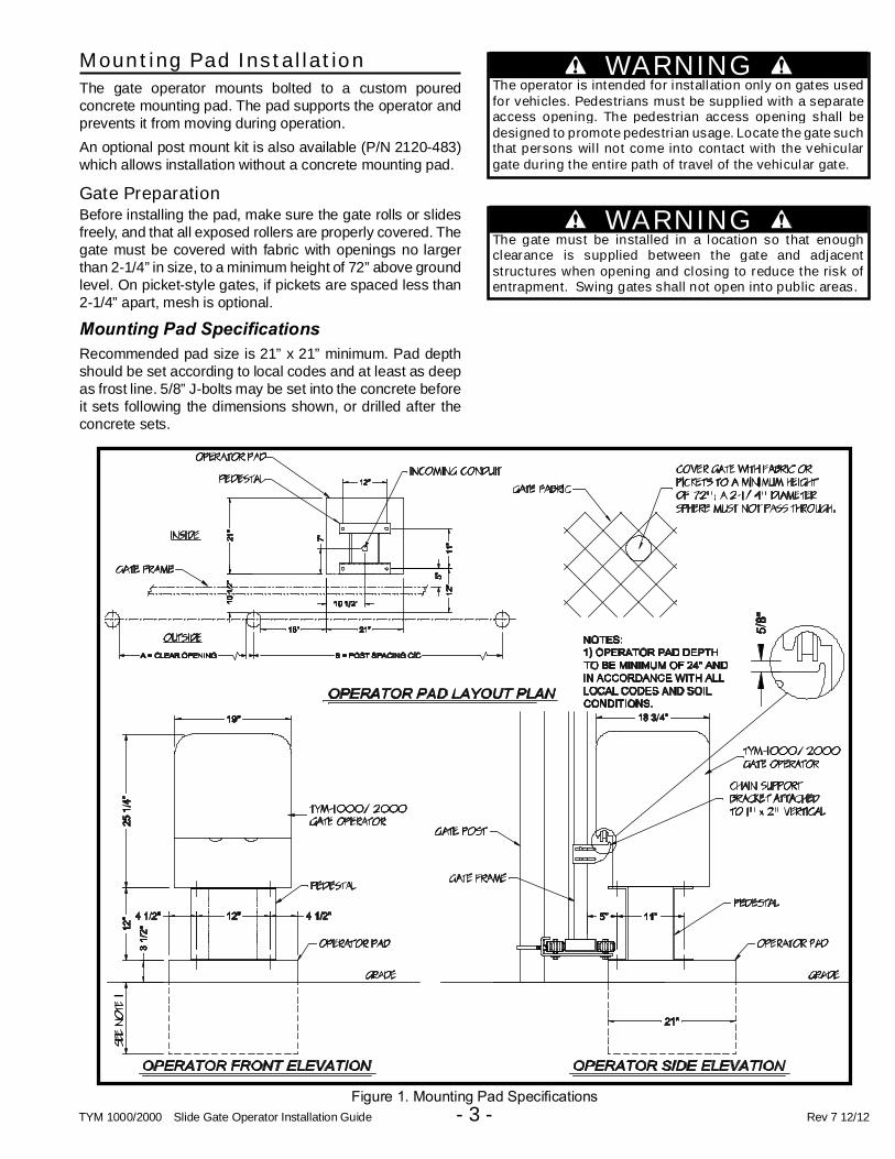
Mounting Pad Installation
The gate operator mounts bolted to a custom pouredconcrete mounting pad. The pad supports the operator andprevents it from moving during operation.
An optional post mount kit is also available (P/N 2120-483)which allows installation without a concrete mounting pad.
Gate PreparationBefore installing the pad, make sure the gate rolls or slidesfreely, and that all exposed rollers are properly covered. Thegate must be covered with fabric with openings no largerthan 2-1/4” in size, to a minimum height of 72” above groundlevel. On picket-style gates, if pickets are spaced less than2-1/4” apart, mesh is optional.
Mounting Pad Specifi cations
Recommended pad size is 21” x 21” minimum. Pad depthshould be set according to local codes and at least as deepas frost line. 5/8” J-bolts may be set into the concrete beforeit sets following the dimensions shown, or drilled after theconcrete sets.
Figure 1. Mounting Pad Specifi cations
WARNINGThe operator is intended for installation only on gates usedfor vehicles. Pedestrians must be supplied with a separateaccess opening. The pedestrian access opening shall bedesigned to promote pedestrian usage. Locate the gate suchthat persons will not come into contact with the vehiculargate during the entire path of travel of the vehicular gate.
WARNINGThe gate must be installed in a location so that enoughclearance is supplied between the gate and adjacentstructures when opening and closing to reduce the risk ofentrapment. Swing gates shall not open into public areas.

TYM 1000/2000 Slide Gate Operator Installation Guide - 4 - Rev 7 12/12
Figure 2: Operator Positioning - Parallel Placement
TYM 1000/2000 Slide Gate Operator Installation Guide - 5 - Rev 7 12/12
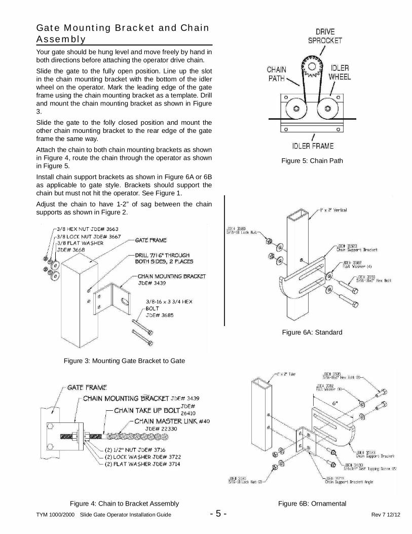
Gate Mounting Bracket and ChainAssembly
Your gate should be hung level and move freely by hand inboth directions before attaching the operator drive chain.
Slide the gate to the fully open position. Line up the slotin the chain mounting bracket with the bottom of the idlerwheel on the operator. Mark the leading edge of the gateframe using the chain mounting bracket as a template. Drilland mount the chain mounting bracket as shown in Figure3.
Slide the gate to the folly closed position and mount theother chain mounting bracket to the rear edge of the gateframe the same way.
Attach the chain to both chain mounting brackets as shownin Figure 4, route the chain through the operator as shownin Figure 5.
Install chain support brackets as shown in Figure 6A or 6Bas applicable to gate style. Brackets should support thechain but must not hit the operator. See Figure 1.
Adjust the chain to have 1-2” of sag between the chainsupports as shown in Figure 2.
Figure 6B: Ornamental
Figure 6A: Standard
Figure 5: Chain Path
Figure 3: Mounting Gate Bracket to Gate
Figure 4: Chain to Bracket Assembly
TYM 1000/2000 Slide Gate Operator Installation Guide - 6 - Rev 7 12/12
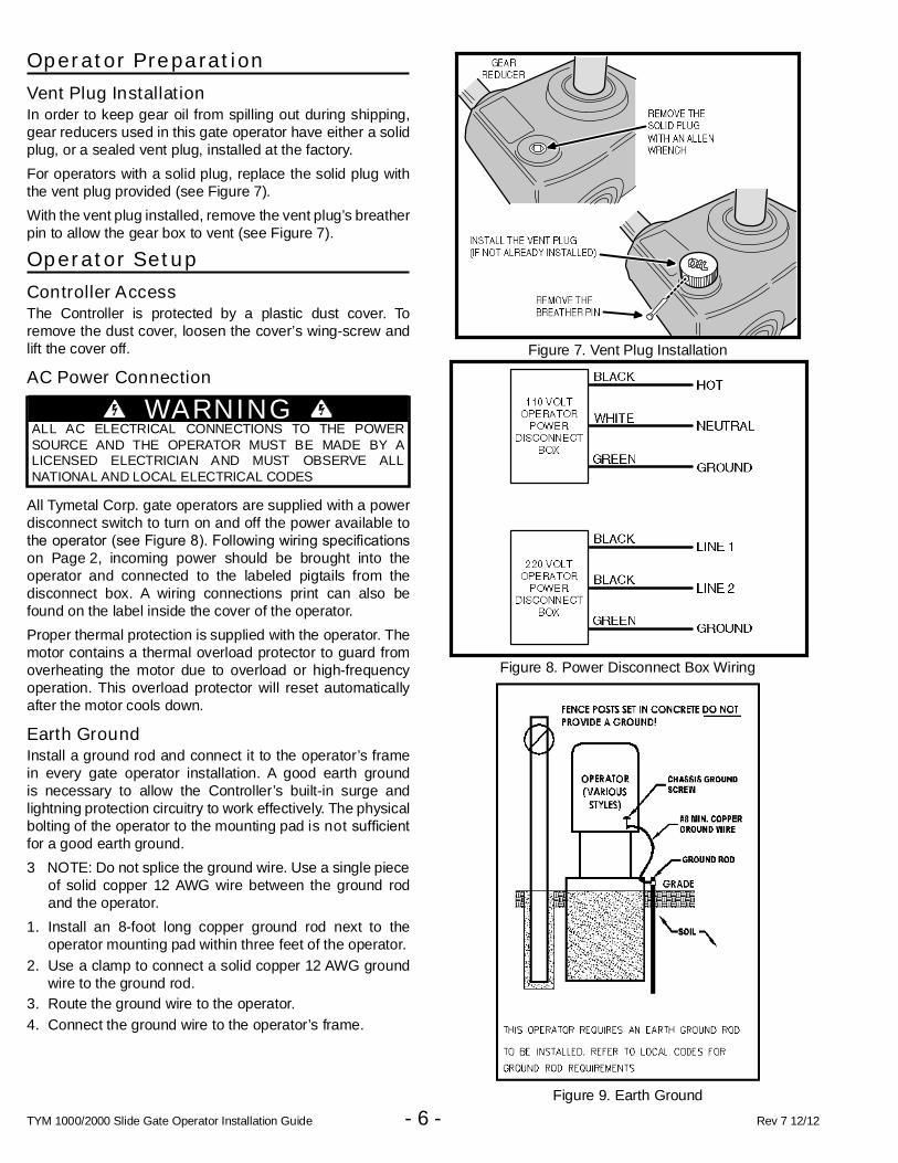
Operator Preparation
Vent Plug InstallationIn order to keep gear oil from spilling out during shipping,gear reducers used in this gate operator have either a solidplug, or a sealed vent plug, installed at the factory.
For operators with a solid plug, replace the solid plug withthe vent plug provided (see Figure 7).
With the vent plug installed, remove the vent plug’s breatherpin to allow the gear box to vent (see Figure 7).
Operator Setup
Controller AccessThe Controller is protected by a plastic dust cover. Toremove the dust cover, loosen the cover’s wing-screw andlift the cover off.
AC Power Connection
All Tymetal Corp. gate operators are supplied with a powerdisconnect switch to turn on and off the power available tothe operator (see Figure 8). Following wiring specifi cations on Page 2, incoming power should be brought into theoperator and connected to the labeled pigtails from thedisconnect box. A wiring connections print can also befound on the label inside the cover of the operator.
Proper thermal protection is supplied with the operator. Themotor contains a thermal overload protector to guard fromoverheating the motor due to overload or high-frequencyoperation. This overload protector will reset automaticallyafter the motor cools down.
Earth GroundInstall a ground rod and connect it to the operator’s framein every gate operator installation. A good earth groundis necessary to allow the Controller’s built-in surge andlightning protection circuitry to work effectively. The physicalbolting of the operator to the mounting pad is not suffi cient for a good earth ground.
3 NOTE: Do not splice the ground wire. Use a single pieceof solid copper 12 AWG wire between the ground rodand the operator.
1. Install an 8-foot long copper ground rod next to theoperator mounting pad within three feet of the operator.
2. Use a clamp to connect a solid copper 12 AWG groundwire to the ground rod.
3. Route the ground wire to the operator.
4. Connect the ground wire to the operator’s frame.
Figure 8. Power Disconnect Box Wiring
Figure 7. Vent Plug Installation
WARNINGALL AC ELECTRICAL CONNECTIONS TO THE POWERSOURCE AND THE OPERATOR MUST BE MADE BY ALICENSED ELECTRICIAN AND MUST OBSERVE ALLNATIONAL AND LOCAL ELECTRICAL CODES
Figure 9. Earth Ground

TYM 1000/2000 Slide Gate Operator Installation Guide - 7 - Rev 7 12/12
Operator Setup (Continued)
Limit Nuts Rough AdjustmentThe limit nuts are not preset at the factory and must beadjusted for the length of the gate in each installation. Thelimit switches are activated by two threaded nylon rotarylimit nuts which are attached to a threaded limit shaftdriven by a chain and sprockets from the main drive shaft(see Figure 10). REMOVE THE CARDBOARD FILLERBEFORE ADJUSTING THE LIMIT NUTS.
The Controller is factory set for right hand installations. Theleft limit nut is for OPEN and the right limit nut is for CLOSE.The limit nuts fl ip their defi nition in left hand installations. (see left-right hand programming on Page 12).
1. With the gate connected to the gate operator in a mid-travel position, the power disconnect switch turned OFF,disconnect the operator by using the manual disconnectlever. Once the operator has been disconnected,manually move the gate by hand to within a foot of itsfully open position (the foot of distance is necessary toallow for coasting of the operator after the limit switch istripped).
2. Once the gate is in this position, adjust the OPEN limitnut until it activates the limit switch for open. Press downthe detent plate and rotate the nut along the threadedshaft (see Figure 10).
3. After setting the open limit, move the gate to one footfrom fully closed and repeat the process for the CLOSElimit nut (see Figure 10).
Limit Nuts Fine AdjustmentAfter fi nishing the rough limit nut adjustments, reposition the gate to approximately the center of travel.
1. Re-engage the operator using the disconnect handle.
2. Turn the power disconnect switch ON.
3. Stand clear of any moving parts and press the OPENbutton.
4. After the gate opens, press the CLOSE button.
5. Observe the gate in both directions as it runs througheach complete cycle. Adjust the open or close limitnuts again if necessary. Fine levels of adjustment canbe made by adjusting a few teeth on the nut at a time.If the gate stops during travel, you may need to adjustthe Open or Close Current Setting or the Maximum RunTimer (see Pages 13-14).
Figure 11. Setting the Limits
CAUTIONIf the operator is installed in a left-hand installation. Setthe Controller to left-hand operation BEFORE running theoperator for the fi ne setting of the limit nuts. Failure to do so will result in over-shooting the limit switches, and can causedamage to the operator and/or gate. Refer to programmingon Page 12.
Figure 10. Limit Box AssemblyNOTE: Auxiliary limit switches are located below limit shaftand can be used for gate status.
Left-Hand To Open Right-Hand To Open
Limit ShaftLimit Nuts
CLOSE LIMIT OPEN LIMIT OPEN LIMIT CLOSE LIMIT
Auxiliary Limit Switches

TYM 1000/2000 Slide Gate Operator Installation Guide - 8 - Rev 7 12/12
Controller Features
Figure 12. Controller Features

TYM 1000/2000 Slide Gate Operator Installation Guide - 9 - Rev 7 12/12
Indicator Descriptions
INDICATOR DEFINITION INDICATION WHEN LITDURING NORMAL OPERATION
INDICATION WHEN LITDURING PROGRAMMINGOPERATION PROGRAMMING
24 VOLT INPUTPOWER
LOW VOLTAGE AC POWER IS PRESENT
24 VOLT DCACCY POWER
LOW VOLTAGE DC POWER IS PRESENT
OPENOPEN SIGNAL PRESENT FROM THE INTERNALRECEIVER OR AN EXTERNAL DEVICECONNECTED TO THE OPEN INPUT TERMINAL
CLOSECLOSE SIGNAL IS PRESENT FROM A DEVICECONNECTED TO THE CLOSE INPUT TERMINAL
STOPSTOP INPUT TERMINAL IS OPEN ANDNOT CONNECTED TO COMMON
PROGRAM CONTROLLER IS IN PROGRAMMING MODE
REVERSE DELAY SET SIGNAL FROM REVERSING DEVICE IS PRESENT SET REVERSE DELAY TIME
LOCKOUT ALARM SETCONTROLS AND OPERATOR ARE LOCKED OUTBECAUSE OF EXISTING TROUBLE CONDITION
SET RUN ALARM AND PRE-START ALARM
RADIO LEARNBUILT-IN RECEIVER IS DETECTING A RADIOSIGNAL FROM A REMOTE CONTROL
TRANSMITTERS CAN BE ENTERED INTOMEMORY (UP TO 40 TRANSMITTERS)
OPEN CURRENT SETMOTOR CURRENT HAS EXCEEDED THEOPEN CURRENT SETTING WHILE OPENING
SET MAXIMUM OPEN CURRENT
OPEN OBSTR MGT 2 SET
OPEN OBSTRUCTION TERMINALCONNECTED TO COMMON BY BEAM ORREVERSING EDGE, OR SIGNAL FROMMGT OBSTACLE TRANSMITTER
SET MGT #2 FUNCTION
OPEN RELAY LH/RH SET OPEN RELAY IS ACTIVATED SET LEFT-HAND RIGHT-HAND OPERATION
OPEN LIMIT BRAKE DELAY OPEN LIMIT SWITCH IS ACTIVATED
CLOSE CURRENT SETMOTOR CURRENT HAS EXCEEDED THECLOSE CURRENT SETTING WHILE CLOSING
SET MAXIMUM CLOSE CURRENT
CLOSE OBSTR MGT 1 SET
CLOSE OBSTRUCTION TERMINALCONNECTED TO COMMON BY BEAM ORREVERSING EDGE, OR SIGNAL FROMMGT OBSTACLE TRANSMITTER
SET MGT #1 FUNCTION
CLOSE RELAY AUTO CLOSE SET CLOSE RELAY IS ACTIVATED SET AUTO-CLOSE TIME
CLOSE LIMIT AC DC SET CLOSE LIMIT SWITCH IS ACTIVATED SET MOTOR TYPE
SINGLE SETSINGLE TERMINAL CONNECTED TO COMMONBY AN EXTERNAL PUSHBUTTON OR RADIO
SET SINGLE BUTTON INPUT FUNCTION
MAX RUN SET MAXIMUM RUN TIMER HAS BEEN EXCEEDED SET MAXIMUM RUN TIME
COMM LINK SETDUAL OPERATOR CONNECTION DETECTED,BLINKS IF CONNECTION HAS FAILED
MAINT ALERT SET MAINTENANCE IS REQUIRED ON OPERATOR SET MAINTENANCE ALERT CYCLE COUNT

TYM 1000/2000 Slide Gate Operator Installation Guide - 10 - Rev 7 12/12
Terminal Descriptions
TERMINAL GROUP FUNCTION
AC N24 VOLT INPUT
FACTORY CONNECTED TO 24 VAC FROM TRANSFORMER OR24 VDC FROM CONTINUOUS DUTY DC SUPPLY.AC
DC -ACCESSORY POWER PROVIDES 24 VOLT DC POWER FOR ACCESSORIES. (.5A MAX)
DC +
RESETRESET BUTTON FACTORY CONNECTED TO THE CONTROLLER’S RESET BUTTON.
COMMON
C
COMM LINK FOR 3-WIRE NETWORK CONNECTION TO SECOND OPERATOR IN DUAL GATE INSTALLATIONS.B
A
COMMONSINGLE BUTTON INPUT
CONNECT TO NORMALLY OPEN SWITCH FOR SINGLE BUTTON OPERATION. ALTERNATESBETWEEN OPEN-CLOSE OR OPEN-STOP-CLOSE DEPENDING ON PROGRAMMING.SINGLE
COMMONFIRE BOX INPUT CONNECT TO NORMALLY OPEN SWITCH IN FIRE BOX FOR FIRE DEPARTMENT ACCESS.
FIRE DEPT
COMMONOPEN INPUT
CONNECT TO NORMALLY OPEN DEVICES (KEYPAD, CARD READER, KEYSWITCH,TELEPHONE ENTRY SYSTEM) TO OPEN THE GATE. A CONSTANT OPEN INPUT WILLOVERRIDE THE MID-TRAVEL STOP AND HALT THE AUTO CLOSE TIMER UNTIL RELEASED.
OPEN
OPEN
3-BUTTONSTATION INPUT
CONNECT TO 3-BUTTON STATION FOR OPEN-CLOSE-STOP CONTROL. A CONSTANT OPEN INPUTWILL OVERRIDE THE MID-TRAVEL STOP AND HALT THE AUTO CLOSE TIMER UNTIL RELEASED.
CLOSE
COMMON
STOP
COM
OPENOBSTRUCTIONINPUT
CONNECT TO NORMALLY OPEN DEVICES (GATE EDGE, PHOTO BEAM) TO DETECT ANOBSTRUCTION DURING OPENING. WHILE GATE IS MOVING, ANY OPEN OBSTRUCTIONSIGNAL WILL CAUSE THE GATE TO STOP, REVERSE A SHORT DISTANCE, AND THEN STOPAGAIN. AT THIS TIME THE AUTO CLOSE TIMER IS DISABLED, AND A RENEWED INPUTWILL BE REQUIRED TO START THE GATE AGAIN. SHOULD THE GATE BE RESTARTEDAND THE OBSTACLE SIGNAL OCCUR AGAIN PRIOR TO REACHING A LIMIT, THE GATEWILL STOP AGAIN, LOCKOUT, AND SOUND THE CONTINUOUS TONE ALARM.
O-OBS
C-OBS
CLOSEOBSTRUCTIONINPUT
CONNECT TO NORMALLY OPEN DEVICES (GATE EDGE, PHOTO BEAM) TO DETECT ANOBSTRUCTION DURING CLOSING. WHILE GATE IS MOVING, ANY CLOSE OBSTRUCTIONSIGNAL WILL CAUSE THE GATE TO STOP, THEN REVERSE AND TRAVEL TO THE FULLOPEN POSITION. SHOULD A OPEN OBSTRUCTION INPUT OR AN OPEN DIRECTIONINHERENT ENTRAPMENT CONDITION OCCUR PRIOR TO THE GATE REACHING THEOPEN LIMIT, THE OPERATOR WILL LOCKOUT AND SOUND THE CONTINUOUS TONEALARM. IF THE AUTO CLOSE TIMER IS SET, WHEN THE CLOSE OBSTRUCTION INPUTIS CLEARED, THE GATE WILL CLOSE WHEN THE AUTO CLOSE TIMER EXPIRES.
COM
COMREVERSE
CONNECT TO NORMALLY OPEN DEVICES TO CAUSE A REVERSAL WHEN THE GATE ISTRAVELING CLOSED. THE GATE WILL REVERSE TO THE FULL OPEN POSITION.REV
OPEN LOOPOPEN LOOP
CONNECT TO OPEN LOOP/FREE EXIT LOOP. THE GATE WILL OPENWHEN THE LOOP IS TRIGGERED, AND REMAIN OPEN AS LONG ASTHE LOOP IS TRIGGERED. REQUIRES LOOP DETECTOR.
OPEN LOOP
REVERSE LOOPREVERSE LOOP
CONNECT TO REVERSE LOOP. TRIGGERING THE LOOP WILL CAUSE AREVERSAL WHEN THE GATE IS TRAVELING CLOSED. THE GATE WILL REVERSETO THE FULL OPEN POSITION. REQUIRES LOOP DETECTOR.
REVERSE LOOP
SHADOW/RESET LOOPSHADOW/RESET LOOP
CONNECT TO SHADOW/RESET LOOP TO KEEP THE GATE IN ITS FULLY OPENPOSITION AS LONG AS THE SIGNAL IS PRESENT. USED TO KEEP GATE OPENWHILE VEHICLE IS PASSING THROUGH. REQUIRES LOOP DETECTOR.
SHADOW/RESET LOOP
-ALARM FACTORY CONNECTED TO THE ALARM BEEPER.
+
N.O.
AUX RELAYFOR CONNECTION TO AUXILIARY DEVICES (MAGNETIC LOCK, SOLENOID LOCK,STROBE LIGHT) FOR ACTIVATION (OR DEACTIVATION) DURING GATE OPERATION.
COM
N.C.
+24 VOLT SOLAR PANEL FOR CONNECTION TO 24 VOLT SOLAR PANEL FOR BATTERY CHARGING.
-
+24 VOLT BATTERY FACTORY CONNECTED TO BATTERIES IN DC MODEL OPERATORS.
-

TYM 1000/2000 Slide Gate Operator Installation Guide - 11 - Rev 7 12/12
Operator Accessory Connections
Figure 13. Operator Accessory Connections
N.CN.O
N.O
N.O
See p. 15
TYM 1000/2000 Slide Gate Operator Installation Guide - 12 - Rev 7 12/12
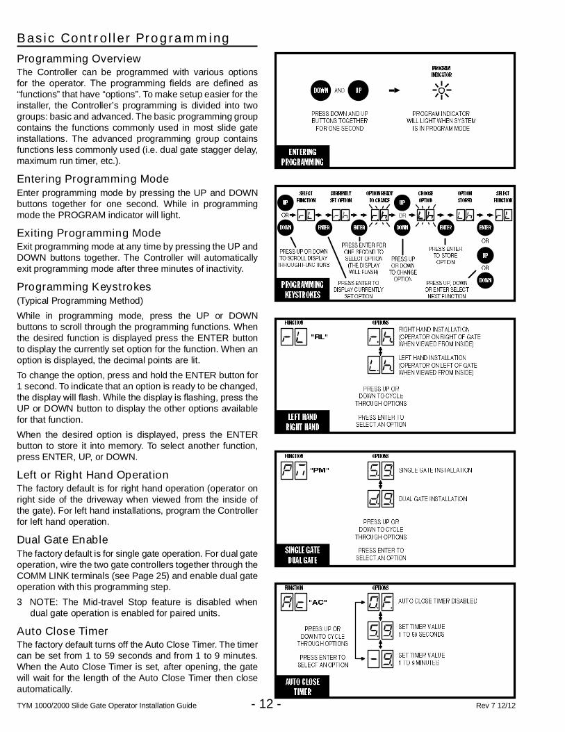
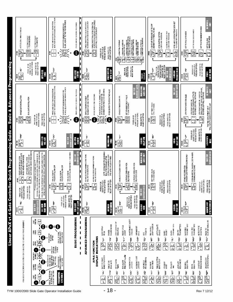
Basic Controller Programming
Programming OverviewThe Controller can be programmed with various optionsfor the operator. The programming fi elds are defi ned as “functions” that have “options”. To make setup easier for theinstaller, the Controller’s programming is divided into twogroups: basic and advanced. The basic programming groupcontains the functions commonly used in most slide gateinstallations. The advanced programming group containsfunctions less commonly used (i.e. dual gate stagger delay,maximum run timer, etc.).
Entering Programming ModeEnter programming mode by pressing the UP and DOWNbuttons together for one second. While in programmingmode the PROGRAM indicator will light.
Exiting Programming ModeExit programming mode at any time by pressing the UP andDOWN buttons together. The Controller will automaticallyexit programming mode after three minutes of inactivity.
Programming Keystrokes(Typical Programming Method)
While in programming mode, press the UP or DOWNbuttons to scroll through the programming functions. Whenthe desired function is displayed press the ENTER buttonto display the currently set option for the function. When anoption is displayed, the decimal points are lit.
To change the option, press and hold the ENTER button for1 second. To indicate that an option is ready to be changed,the display will fl ash. While the display is fl ashing, press the UP or DOWN button to display the other options availablefor that function.
When the desired option is displayed, press the ENTERbutton to store it into memory. To select another function,press ENTER, UP, or DOWN.
Left or Right Hand OperationThe factory default is for right hand operation (operator onright side of the driveway when viewed from the inside ofthe gate). For left hand installations, program the Controllerfor left hand operation.
Dual Gate EnableThe factory default is for single gate operation. For dual gateoperation, wire the two gate controllers together through theCOMM LINK terminals (see Page 25) and enable dual gateoperation with this programming step.
3 NOTE: The Mid-travel Stop feature is disabled whendual gate operation is enabled for paired units.
Auto Close TimerThe factory default turns off the Auto Close Timer. The timercan be set from 1 to 59 seconds and from 1 to 9 minutes.When the Auto Close Timer is set, after opening, the gatewill wait for the length of the Auto Close Timer then closeautomatically.
TYM 1000/2000 Slide Gate Operator Installation Guide - 13 - Rev 7 12/12
Basic Controller Programming(Cont.)
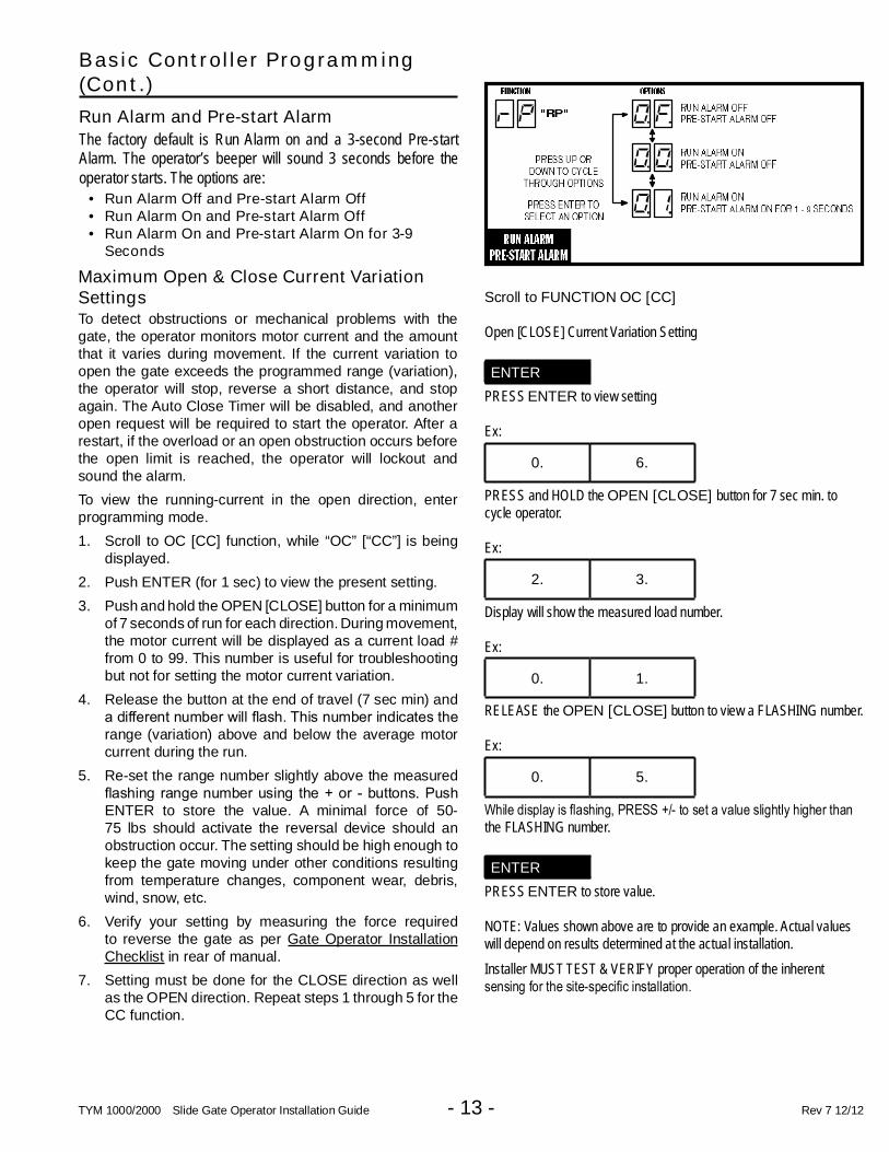
Run Alarm and Pre-start Alarm
The factory default is Run Alarm on and a 3-second Pre-startAlarm. The operator’s beeper will sound 3 seconds before theoperator starts. The options are:
• Run Alarm Off and Pre-start Alarm Off• Run Alarm On and Pre-start Alarm Off• Run Alarm On and Pre-start Alarm On for 3-9
Seconds
Maximum Open & Close Current VariationSettingsTo detect obstructions or mechanical problems with thegate, the operator monitors motor current and the amountthat it varies during movement. If the current variation toopen the gate exceeds the programmed range (variation),the operator will stop, reverse a short distance, and stopagain. The Auto Close Timer will be disabled, and anotheropen request will be required to start the operator. After arestart, if the overload or an open obstruction occurs beforethe open limit is reached, the operator will lockout andsound the alarm.
To view the running-current in the open direction, enterprogramming mode.
1. Scroll to OC [CC] function, while “OC” [“CC”] is beingdisplayed.
2. Push ENTER (for 1 sec) to view the present setting.
3. Push and hold the OPEN [CLOSE] button for a minimumof 7 seconds of run for each direction. During movement,the motor current will be displayed as a current load #from 0 to 99. This number is useful for troubleshootingbut not for setting the motor current variation.
4. Release the button at the end of travel (7 sec min) anda different number will fl ash. This number indicates the range (variation) above and below the average motorcurrent during the run.
5. Re-set the range number slightly above the measuredfl ashing range number using the + or - buttons. Push ENTER to store the value. A minimal force of 50-75 lbs should activate the reversal device should anobstruction occur. The setting should be high enough tokeep the gate moving under other conditions resultingfrom temperature changes, component wear, debris,wind, snow, etc.
6. Verify your setting by measuring the force requiredto reverse the gate as per Gate Operator InstallationChecklist in rear of manual.
7. Setting must be done for the CLOSE direction as wellas the OPEN direction. Repeat steps 1 through 5 for theCC function.
Scroll to FUNCTION OC [CC]
Open [CLOSE] Current Variation Setting
ENTER
PRESS ENTER to view setting
Ex:
0. 6.
PRESS and HOLD the OPEN [CLOSE] button for 7 sec min. tocycle operator.
Ex:
2. 3.
Display will show the measured load number.
Ex:
0. 1.
RELEASE the OPEN [CLOSE] button to view a FLASHING number.
Ex:
0. 5.
While display is fl ashing, PRESS +/- to set a value slightly higher than the FLASHING number.
ENTER
PRESS ENTER to store value.
NOTE: Values shown above are to provide an example. Actual valueswill depend on results determined at the actual installation.
Installer MUST TEST & VERIFY proper operation of the inherentsensing for the site-specifi c installation.

TYM 1000/2000 Slide Gate Operator Installation Guide - 14 - Rev 7 12/12
Advanced ControllerProgramming
Entering Advanced Programming ModeTo access and program the Advanced Programmingfunctions, for each programming session, AdvancedProgramming must be enabled.
After exiting programming, the Advanced Programmingfunctions will be available on the programming display duringthe next programming session unless the operator has run50 or more cycles. After that, Advanced Programming mustbe enabled again.
Maximum Run TimeThe factory default for the Maximum Run Time (MRT) is99 seconds. When the operator starts, a timer will begincounting. If an open or close limit is not reached or anobstacle or reversing input is not received before the timerexpires, the operator will stop, the unit locks out and thealarm sounds. The timer can be set for 10 to 99 seconds.See p. 27 for reset
Single Button Input Setup
This function is used for selecting the operation for singlebutton controls and radio receivers.
The factory default sets the SINGLE input terminal sosuccessive inputs will cycle the operator in OPEN-STOP-CLOSE-STOP order.
Alternately, the SINGLE input can be set to cause the gateto OPEN unless the gate is fully open. If the gate is fullyopen, the input will cause the gate to CLOSE.
Stagger Mode(Rarely used in slide gate installations)
This function is used in dual gate installations only. Thefactory default sets the Stagger Mode to OFF. In dual gateinstallations the two operators communicate through the3-wire COMM LINK interface. When using the StaggerMode, set one operator for delayed opening and the otheroperator for delayed closing. The Stagger Delay Timeprogramming function (see below) sets the length of thedelay.
3 NOTE: This function will only be displayed if dual gateoperation is selected.

TYM 1000/2000 Slide Gate Operator Installation Guide - 15 - Rev 7 12/12
Advanced ControllerProgramming (Cont.)
Stagger Delay Time(Rarely used in slide gate installations)
This function is used in dual gate installations only. Thefactory default sets the Stagger Time to 0 seconds (OFF).The Stagger Time sets the delay for the Stagger Mode. TheStagger Time can be set from 1-99 seconds.
3 NOTE: This function will only be displayed if dual gateoperation is selected.
Auxiliary Relay ModeThe Auxiliary Relay has normally open and normally closedcontacts. The factory setting disables the Auxiliary Relay.The relay can be set for:
• For solenoid locks with in-rush current less than 5a,the APeX AUX Relay will engage during any pendingor actual gate motion (open direction only) to activatea solenoid lock.
• For solenoid locks with in-rush current between 5aand 13a, a separate interface relay is required. TheAPeX AUX Relay will energize during any pending oractual gate motion (open direction only) to activate thesolenoid lock. When the solenoid lock is supplied byTymetal as part of the gate operator order, the interfacerelay is added at manufacture and the controller isproperly programmed to function as above.
• Maglock: The relay will energize during any pending oractual gate motion (open only) to deactivate a magneticgate lock.
• Ticket Dispenser: The relay will be energized at alltimes (enabling a ticket dispenser) unless the operatoris fully open or in an entrapment position.
• Strobe: The relay will energize during any pending oractual gate motion (either open or close) to activate awarning strobe light.
• Alarm: The relay will energize if the gate is manuallyforced open from the full closed position.
Reverse Delay TimeThe factory default sets the Reverse Delay to 1 second. Theoperator will wait the length of the delay before reversingdirection. This feature will not change the reversal timewhen the operator is responding to an entrapment conditionfrom an obstruction input or inherent entrapment protectionsensor. The Reverse Delay can be set from 1 to 9 seconds.Heaver gates require a longer delay to allow time for thegate to stop.

TYM 1000/2000 Slide Gate Operator Installation Guide - 16 - Rev 7 12/12
Advanced ControllerProgramming (Cont.)
Reset Cycle CountThe Controller counts of the number of times the operatorhas been cycled full open and close. The cycle count can bedisplayed. The display will scroll the cycle count number,fl ashing two digits at a time from left to right.
If the Maintenance Alert has been triggered, resetting theCycle Count will also reset the Maintenance Alert indicator.
Maintenance Alert TriggerThe Controller has a MAINT ALERT indicator that canbe programmed to light when the number of activationsexceeds a set number of cycles.
The factory default sets the Maintenance Alert Triggerto 10,000 cycles. The Maintenance Alert Trigger can beprogrammed for 5, 10, 15, or 25 thousand cycles.
The Maintenance Cycle Count can be reset independentlyfrom the operator’s absolute Cycle Count.
Mid-travel Stop PositionThe Controller can be programmed so the gate will stop at amid-travel point instead of fully opening. This can be usefulin installations where a large gate, that takes a long time toopen and close fully, only needs to be opened partway toallow traffi c to pass.
The factory default sets the Controller for full open operation.Alternately, the Controller can be programmed to open for1 to 99 seconds then stop, before reaching the open limit.
When a Mid-travel StopPosition timehasbeen programmed,the gate will still fully open if the Fire Department input istriggered, if the OPEN button is held down beyond the Mid-travel Stop Position, or a close obstruction or reverse loopinput is triggered.
3 NOTE: The Mid-travel Stop feature is disabled whendual gate operation is enabled for paired units.
Motor Type SelectionThe factory sets the default for the Controller to match thetype of motor in the operator. If required, change the motorselection option to a different type of motor used in theoperator. The options available are:
• AC Motor Only• DC Motor Only with Mechanical Braking• DC Motor with Electronic Soft Start/Stop• 3 Phase AC Motor• AC Motor with DC Motor Backup with Mechanical
Braking• AC Motor with DC Motor Backup with Electronic Soft
Start/Stop

TYM 1000/2000 Slide Gate Operator Installation Guide - 17 - Rev 7 12/12
Advanced ControllerProgramming (Cont.)Radio EnableThe Controller contains a built-in MegaCode® radio receiverto allow activation from up to 40 access control transmittersand two Model MGT (gate edge) transmitters. The factorydefault enables the internal radio receiver. Alternately, theinternal receiver can be disabled.
Antenna InstallationThe Controller is supplied with a local whip antenna installed.If using a remote antenna, remove the whip antenna andconnect coax cable from the antenna to the ANTENNAconnector.
Radio Transmitter LearnThe Controller’s built-in MegaCode® radio receiver can storethe IDs of up to 40 transmitters. Refer to the fi gure for the steps required to learn transmitters.
3 NOTE: This function will NOT be displayed if thetransmitter memory is full, or if the radio receiver isdisabled.
Radio Transmitter DeleteTransmitters can be deleted from the Controller’s memoryeither individually, or all at the same time. Refer to the fi gure for the steps required to delete transmitters.
3 NOTE: This function will NOT be displayed if notransmitters are stored in memory, or if the radio receiveris disabled.
MGT Obstacle Transmitter LearnThe Controller supports one or two Model MGT ObstacleTransmitters. The transmitters can be programmed tofunction as Open Obstruction, Close Obstruction, Reverse,or Stop. Refer to the fi gure for the steps required to learn MGT transmitters.
3 NOTE: This function will NOT be displayed if two MGTtransmitters are already stored in memory, or if the radioreceiver is disabled.
MGT Obstacle Transmitter DeleteMGT transmitters can be deleted from the Controller’smemory either individually, or all at the same time. Refer tothe fi gure for the steps required to delete MGT transmitters.
3 NOTE: This function will NOT be displayed if no MGTtransmitters are stored in memory, or if the radio receiveris disabled.
Reset Controller to Factory DefaultsThe Controller can be reset with this function. ALLPROGRAMMED DATA WILL BE LOST, and the factorydefaults will be loaded. This function will not eraseradio transmitters, current sense values, or motor type.Transmitters must be deleted with the two functions above.
TYM 1000/2000 Slide Gate Operator Installation Guide - 18 - Rev 7 12/12

TYM 1000/2000 Slide Gate Operator Installation Guide - 19 - Rev 7 12/12
TYM 1000/2000 Slide Gate Operator Installation Guide - 20 - Rev 7 12/12
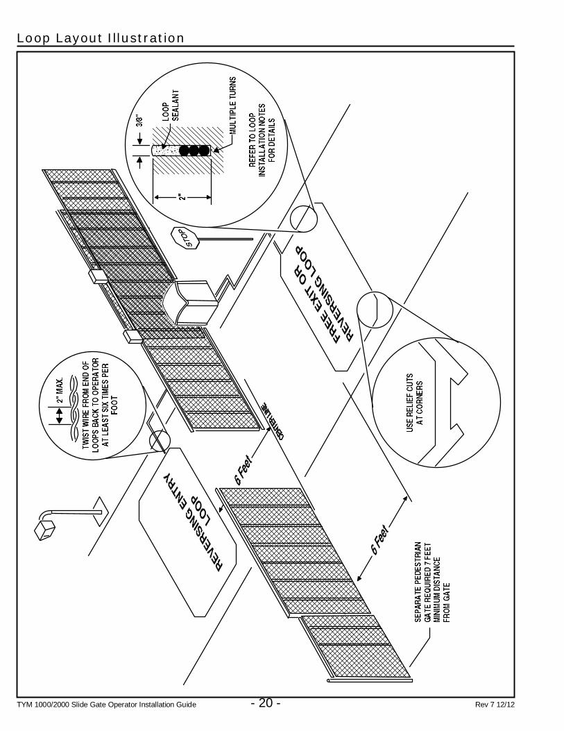
Loop Layout Illustration
TYM 1000/2000 Slide Gate Operator Installation Guide - 21 - Rev 7 12/12
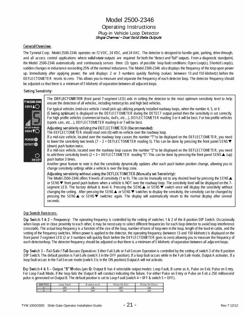
Model 2500-2346Operating Instructions
Plug-in Vehicle Loop Detector
The Tymetal Corp. Model 2500-2346 operates on 12 VDC, 24 VDC, and 24 VAC. The detector is designed to handle gate, parking, drive-through,
and all access control applications where outputs are required for both the “detect and “fail” outputs. From a diagnostic standpoint,
the Model 2500-2346 automatically and continuously senses three (3) types of possible loop fault conditions: Open Loop(s), Shorted Loop(s),
sudden changes in inductance exceeding 25% of the nominal inductance. The Model 2500-2346 also displays the frequency of the loop upon power
up. Immediately after applying power, the unit displays 2 or 3 numbers quickly flashing (values between 13 and 150 kilohertz) before the
DEFLECTOMETER resets to zero. This allows you to measure and separate the frequency of each detector loop. The detector frequency should
be adjusted so that there is a minimum of 5 kilohertz of separation between all adjacent loops.
The (front panel 7-segment LED) aids in setting the detector to the most optimum sensitivity level to helpensure the detection of all vehicles, including motorcycles and high bed vehicles.
For typical vehicles (mid-size vehicle / small pick up) utilizing properly installed roadway loops, when the number 4, 5, or 6is displayed on the DEFLECTOMETER during the DETECT output period then the sensitivity is set correctly.
For high profile vehicles (commercial trucks, 4x4’s, etc…), DEFLECTOMETER reading 3 or 4 will be best. For low profile vehicles(sports cars, etc…), DEFLECTOMETER reading 6 or 7 will be best.
:The DEFLECTOMETER should read zero (0) with no vehicle over the roadway loop.If a mid-size vehicle, located over the roadway loop causes the number “7” to be displayed on the DEFLECTOMETER, you needto lower the sensitivity two levels (7 – 2 = DEFLECTOMETER reading 5). This can be done by pressing the front panel SENS(down) push button twice.If a mid-size vehicle, located over the roadway loop causes the number “2” to be displayed on the DEFLECTOMETER, you needto add three sensitivity levels (2 + 3 = DEFLECTOMETER reading “5”. This can be done by pressing the front panel SENS (up)push button 3 times.Another great feature to note is that the sensitivity dynamically updates after each push button position change, allowing you tochange sensitivity settings while a vehicle is over the loop zone.
The Model 2500-2346 offers 9 levels of sensitivity (1 to 9). This can be manually set to any desired level by pressing the SENSor SENS front panel push buttons when a vehicle is NOT over the roadway loop. The sensitivity level will be displayed on the 7-segment LED. The factory default is level 4. Pressing the SENS or SENS switch once will display the sensitivity withoutchanging the setting. After pressing the SENS or SENS switches to display the sensitivity, the sensitivity can be changed bypressing the SENS or SENS switches again. The display will automatically return to the normal display after severalseconds.
: The operating frequency is controlled by the setting of switches 1 & 2 of the 8 position DIP Switch. Occasionallywhen loops are in close proximity to each other, it may be necessary to select different frequencies for each loop detector to avoid loop interference(crosstalk). The actual loop frequency is a function of the size of the loop, number of turns of loop wire in the loop, length of the lead-in cable, and thesetting of the frequency switches. When power is applied to the detector, the operating frequency (between 13 and 150 kilohertz) is displayed on thefront panel 7-segment LED (2 or 3 numbers will quickly flash before the DEFLECTOMETER goes to zero) allowing you to measure the frequency ofeach detector/loop. The detector frequency should be adjusted so that there is a minimum of 5 kilohertz of separation between all adjacent loops.
: Either Fail-Safe or Fail-Secure Operation is controlled by the setting of switch 3 of the 8 positionDIP Switch. The default position is Fail-Safe (switch 3 in the OFF position). If a loop fault occurs while in the Fail-Safe mode, Output A activates. If aloop fault occurs in the Fail-Secure mode (switch 3 is in the ON position) Output A will not activate.
: Output B has 4 selectable output modes: Loop Fault, B same as A, Pulse on Exit, Pulse on Entry.For Loop Fault Mode, if the loop fails the Output B will conduct indicating the failure. For either Pulse on Entry or Pulse on Exit a 250 millisecondpulse is generated on Output B. The default position is set to Loop Fault (switch 4 = 0FF & switch 5 = OFF).
SWITCH Loop Fault B same as A Pulse On Exit Pulse On Entry
4 0FF ON OFF ON5 0FF OFF ON ON
TYM 2300-2346

TYM 1000/2000 Slide Gate Operator Installation Guide - 22 - Rev 7 12/12
: The default position is set to OFF. When switch 6 is in the ON position, a 2-second “detect” delay feature will delayoutputs A & B for a period of 2 seconds after a vehicle has entered the detection zone. Note that the DEFLECTOMETER will display the letter “d” for“Delay Time”. If the vehicle does not remain in the loop zone for the full 2 seconds the delay will terminate and no DETECT output will be produced.
: Output A has 2 selectable output modes: Infinite Presence and Normal Presence. The default position is InfinitePresence (switch 7 = OFF). In the Infinite Presence mode, a presence output will always be maintained as long as a vehicle is over the loop andpower is not removed for more than approximately 3 seconds. In the Normal Presence mode (switch 7 = ON), the output hold time is between 5minutes minimum and 3 hours maximum. Hold time depends on loop geometry; number of wire turns in the loop, vehicle size, and position of thevehicle relative to the loop.
: The default position is set to OFF. When switch 8 is in the ON position and when a vehicle enters the loop zone,the detector sensitivity is boosted to a higher level than the vacant loop setting. The boosted sensitivity remains throughout the DETECT period.When the vehicle leaves the loop zone, the sensitivity returns to the vacant loop setting. This feature is designed to automatically increase sensitivityonly during the DETECT output period. This feature aids in preventing dropouts during the passage of high bed vehicles and is particularly useful insliding gate situations.
: The detector continuously checks the integrity of the loop. The system is able to detect open or shorted circuit loops, orsudden changes in inductance exceeding 25% of the nominal inductance. If a fault is detected, the POWER and DETECT LED both continuouslyemit a sequence of flashes. Additionally, the 7-Segment DEFLECTOMETER displays F1, F2, or F3 indicating a current loop fault. Each type of faultis identified by a different flash sequence:
Flash Sequence Deflectometer Display Fault Condition1 flash F 1 Open Circuit Loop2 flashes F 2 Shorted Circuit Loop3 flashes F 3 25% excessive change in inductance
If the Open or Shorted fault condition self heals, the DETECT LED and 7-Segment DEFLECTOMETER will return to normal operation. Only thePOWER LED will continue to flash with the sequence signifying the type of fault that was last detected. In the case of the excessive inductancechange (F3) fault, the unit will retune to the new inductance after a period of two seconds and continue operation. The previous fault condition will beindicated by the flash sequence of the only POWER LED. Pressing the “Reset” button will reset the detector and clear the flash sequence from thePOWER LED. If you want to review the last loop fault condition, simply press and hold the “Reset” button for 2 seconds and the DETECT LED willdisplay the previous loop fault condition.
:
1 Loop 6 Output B2 Loop 7 Output B Inverted3 Power (12-24VDC, 24Vac) 8 Output A (Presence Output)4 No Connection 9 Power (12-24VDC, 24Vac)5 No Connection 10 Common
Note: Power may be applied on either pin 3 or 9, or both
TYM 1000/2000 Slide Gate Operator Installation Guide - 23 - Rev 7 12/12
Tymetal’s Model MGT Gate Reversing Edge Transmitter iscompatible with the APeX Controller used in Tymetal’s swingand slide gate operators. The MGT transmitter is designedto connect to normally open gate edge contacts and is fullysupervised.
During normal operation, when the edge contact detects anobstruction while the gate is moving, the MGT transmitterwill send an obstacle signal to the APeX Controller and stopor reverse the gate.
Being supervised, the MGT transmitter sends hourly statusreports. It also sends trouble signals to the APeX Controllerwhen the transmitter detects a trouble condition. When atrouble signal is sent to the APeX Controller, the run alarmsounder will beep fast and continue beeping for fi ve minutes, then the sounder will chirp every fi ve seconds while the gate is idle. To clear the trouble annunciation at the gate, thetransmitter’s trouble condition must be corrected fi rst,then the Controller’s power must be cycled off and on.
Four conditions regarding the MGT transmitter can causethe APeX Controller to sound the audible trouble warning:
• MGT transmitter case has been opened.
• Disconnected or shortened reversing edge when MGTtransmitter edge supervision is enabled.
• Low batteries in the MGT transmitter.
• Hourly supervision signals from the MGT transmitterhave not been received by the controller.
MGT Transmitter Troubleshooting
When troubleshooting an MGT transmitter, fi rst open the MGT and check the unit’s internal indicators. The POWERindicator should light when the reversing edge is pressed orthe TEST button is pressed. If it fl ashes, the batteries are low. The LOOP TROUBLE indicator will light when the TESTbutton is pressed if the SENSOR TEST jumper is enabledand the reversing edge wiring is open or shorted.
Tamper Supervision
The MGT transmitter contains a spring loaded tamper switchthat detects if the case is open. When the case is opened,the transmitter will immediately send a trouble transmission.Anytime the transmitter is serviced, you will need to open thecase. After closing the MGT case, cycle the Controller’spower to clear the trouble annunciation.
Edge Supervision
MGT transmitters can monitor the connection to the gateedge if the gate edge is equipped with an internal 100µfcapacitor. There is a jumper in the MGT that enables ordisables the gate edge connection monitoring. If edgemonitoring is enabled, and the connection to the gate edgeis open or shorted, the MGT will send a trouble transmissionwith the next hourly status report to the controller. Usethe transmitter’s jumper to disable edge supervisionif the reversing edge does not contain a capacitor (thetrouble loop indicator stays lit in the MGT transmitter).The jumper does not affect the transmitter’s hourly statusreports.
Low Battery Supervision
MGT transmitters monitor their battery condition and willsend a trouble transmission with the next hourly statusreport to the Controller when the battery tests low. Replacethe batteries, close the MGT case, and power cycle thecontroller.
Status Supervision
MGT transmitters send hourly status reports to theController. The Controller expects those hourly status reports(this cannot be disabled in the APeX Controller). When thecontroller counts four missing transmitter status reports,the trouble annunciation will occur. This could occur fromtransmitter trouble or poor radio reception by the controller.
Open the MGT and test the transmitter by viewing it’sindicators and pressing on the reversing edge. If thetransmitter tests OK, check the radio range of the Controllerusing a handheld transmitter. If a handheld transmittercannot reliable activate the operator at the distance the MGTis from the controller, remotely mount the local antenna oruse an external receiver antenna (Model EXA-1000 or EXA-2000). Also, Tymetal’s Model FT-1 Radio Interference FieldTester can be used to test the installation for abnormal radiointerference conditions.
Using MGT Gate Reversing Edge Transmitters with the APeX Controller
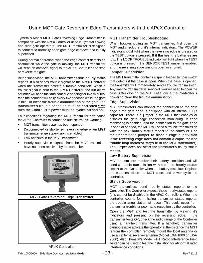
MGT Gate Reversing Edge Transmitter
APeX Controller
TYM 1000/2000 Slide Gate Operator Installation Guide - 24 - Rev 7 12/12
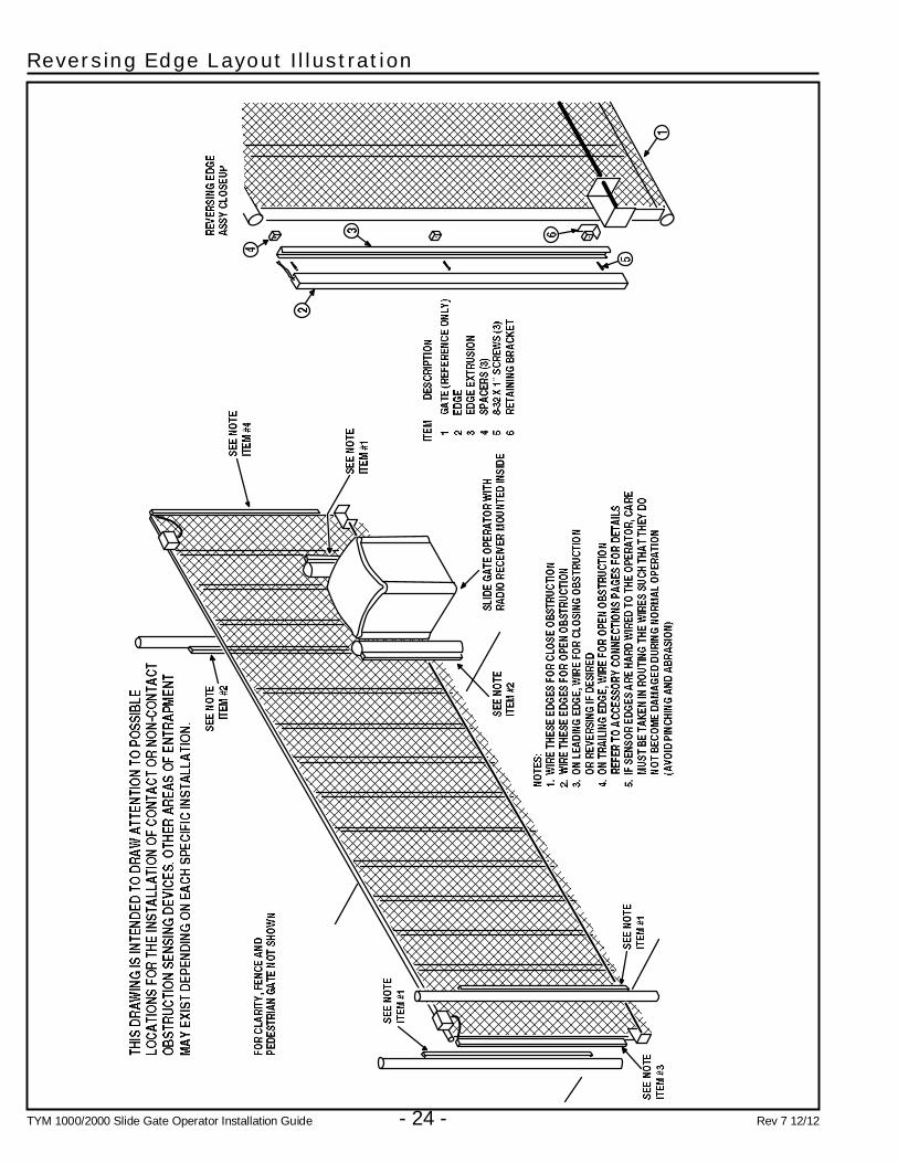
Reversing Edge Layout Illustration

TYM 1000/2000 Slide Gate Operator Installation Guide - 25 - Rev 7 12/12
Photoeye Installation Illustration

TYM 1000/2000 Slide Gate Operator Installation Guide - 26 - Rev 7 12/12
Picket Gate Installation
TYM 1000/2000 Slide Gate Operator Installation Guide - 27 - Rev 7 12/12
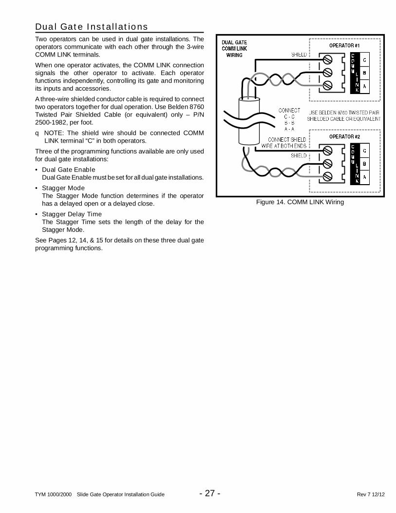
Dual Gate Installations
Two operators can be used in dual gate installations. Theoperators communicate with each other through the 3-wireCOMM LINK terminals.
When one operator activates, the COMM LINK connectionsignals the other operator to activate. Each operatorfunctions independently, controlling its gate and monitoringits inputs and accessories.
A three-wire shielded conductor cable is required to connecttwo operators together for dual operation. Use Belden 8760Twisted Pair Shielded Cable (or equivalent) only – P/N2500-1982, per foot.
q NOTE: The shield wire should be connected COMMLINK terminal “C” in both operators.
Three of the programming functions available are only usedfor dual gate installations:
• Dual Gate EnableDual Gate Enable must beset for all dual gate installations.
• Stagger ModeThe Stagger Mode function determines if the operatorhas a delayed open or a delayed close.
• Stagger Delay TimeThe Stagger Time sets the length of the delay for theStagger Mode.
See Pages 12, 14, & 15 for details on these three dual gateprogramming functions.
Figure 14. COMM LINK Wiring
TYM 1000/2000 Slide Gate Operator Installation Guide - 28 - Rev 7 12/12
Gate Operation
Open Button
Opens the gate. If the Controller is programmed to stopopening the gate at mid-travel, a constant press of the OPENbutton will override the Mid-travel Stop and completely openthe gate. If the Auto Close Timer is set, it will be suspendeduntil the OPEN button is released.
Close Button
Closes the gate if the gate is open. Also closes the gate ifthe gate is in the process of opening.
Stop Button
Stops the gate from opening or closing at any time.
Single Input
Opens the gate if it’s closed and closes the gate if it’s open(open-close programming option). Activating the input whilethe gate is moving will reverse the gate.
Can be programmed to stop the gate while the gate ismoving (open-stop-close programming option).
Fire Department Input
Fully opens the gate when the input is activated. Overridesthe Mid-travel Stop and Auto Close Timer (if either isprogrammed for the gate). The gate will lockout in the openposition without sounding the alarm. Press the STOP buttonto release the lockout.
Fire Department Access
Tymetal can provide an option for Fire DepartmentAccess via a lock box style remote release to accept a fi re department padlock.
When the FD Access Box is mounted on the exterior of thefence line, this arrangement allows the fi re dept to come up to a locked gate, unlock and remove their padlock, andopen the gate for emergency access.
If there is power on the gate, the gate will open automaticallyvia a micro-switch in the box door that is wired to the FIREDEPT terminals in the APeX controller. The gate will stayopen until reset by pressing the STOP button or the RESETbutton on the controller.
If the power is out, there is a handle inside the access boxthat can be pulled out to mechanically release the operatordrive sprocket to allow the gate to be manually pushedopen. The handle will be required to be pushed back inwardto continue normal gate operation.
Nore that a Knox brand padlock has a dust shield for thekey, is plastic armored, and retains the key when unlocked.Knox supplies the keys to fi re departments and assigns a specifi c key code for each fi re districe so that only one key is needed to open any Knox lock within a district.
For a drawing and pricing, please contact Tymetal Corp. inNY at (800)328-4283.
Open Input
Functions the same as the OPEN button.
Open Obstruction
While the gate is opening, any open obstruction signal willcause the gate to stop, reverse a short distance, and thenstop again. The Auto Close Timer will be disabled, and arenewed input will be required to start the gate again. Shouldthe gate be restarted and the obstacle signal occur againprior to reaching a limit, the gate will stop again, lockout,and sound the emergency alarm.
Close Obstruction
While the gate is closing, any close obstruction signal willcause the gate to stop and reverse to full open. If auto closetimer is set, gate will close when the obstruction is clearand the timer expires. Should an open obstruction input oropen direction inherent entrapment condition exist prior toreaching open limit, the operator will lockout and sound thecontinuous tone alarm.
Reverse Input
If the reverse input is triggered while the gate is closing, thegate will reverse to the full open position. If the Auto CloseTimer is set, when the reverse input is cleared, the gate willclose when the Auto Close Timer expires.
Open Loop
Functions the same as the OPEN button.
Reverse Loop
Functions the same as the reverse input.
Shadow/reset Loop
Only used with Swing Gates. Holds the gate fully openor fully closed while triggered. If open, the gate closesimmediately when cleared.

TYM 1000/2000 Slide Gate Operator Installation Guide - 29 - Rev 7 12/12
Operation Indications
During normal operation, the Controller’s displays willindicate current operating conditions and status.
Power-up Display
When the Controller powers up, dashes will show on thedisplay for one second, then the fi rmware version number will be displayed for one second.
Idle Condition
While the Controller is idling, waiting for a command, thedisplay will show circulating dashes.
Last Gate Position/Condition
When the gate moves or stops, the display will show thestatus for up to one minute.
• Stop is displayed as
• Full Close is displayed as
• Full Open is displayed as
• Entrapment is displayed as
Pre-start Delay
During the pre-start delay, the display will countdown thenumber of seconds remaining before the operator starts.
Reverse Delay
If the gate travel direction is reversed from a user activationor reversing device, and a reverse delay is set, the displaywill count down the delay time in seconds before theoperator restarts.
Run Timer
While the gate is opening or closing, the number of secondsrunning time is displayed.
Error Indications
During abnormal operation, the Controller’s displays andbeeper will indicate the error condition that has occurred.
Entrapment or Obstruction Reset
If an entrapment condition occurs detected by two repeatedopen or close obstruction triggers, the Controller will lockthe operator out. The beeper will sound constantly and thegate will not operate. To reset the Controller press the STOPbutton or press the RESET button on the operator’s cover.
COMM LINK Connection Failure
In dual gate installations, if there is a connection failurebetween the two operators, the COMM LINK indicator willblink once a second. During this condition the gate will notoperate, except if triggered by the FIRE DEPT input, whichfunctions normally.
MGT Obstacle Transmitter Trouble
If any MGT transmitters are used with the operator, theirsupervision feature will alert the Controller if there is anytrouble with the transmitter. MGT transmitters send hourlystatus reports and will send low battery reports when thetransmitter has a low battery. The MGT transmitters alsohave a tamper detection switch that will trigger when theircase is opened.
When the Controller detects a low transmitter battery, atamper signal, or missing transmitter status reports, thegate will still operate normally, but the beeper will changeas follows:
• The Pre-start Alarm will beep twice as fast.• The Run Alarm will beep twice as fast and continue for fi ve minutes
after the gate stops.• The sounder will “chirp” every fi ve seconds when the gate is idle.
Correct the trouble (close case, replace battery, or replacetransmitter) to clear the obstacle transmitter troubleindications.
Maximum Run Time Exceeded
If the Maximum Run Time is exceeded, the Controller stopsthe operator the same as if a double obstacle has occurredin an entrapment condition. The entrapment alarm soundsconstantly, and is cleared by pressing the STOP button or theRESET button on the cover. After the STOP or RESET buttonis pressed, because the Maximum Run Time has beenexceeded, the sounder will beep twice every fi ve seconds. The next operation of the gate will clear the indication.
CONTROLLER ERROR CAUSES AND INDICATIONS
ERROR CAUSE ERROR INDICATION HOW TO CLEAR
TWO SAFETY REVERSALS (ON
SINGLE GATE OR ON EITHER
DUAL GATE)
, CONTINUOUS ALARMBEEPER, GATE DISABLED
PRESS STOP BUTTON
MAXIMUM RUN TIMER
EXCEEDED ON OPENING
, AND MAX RUN LED,CONTINUOUS ALARM BEEPER,
GATE DISABLED
PRESS STOP BUTTON,
CLEARS CONTINUOUS ALARM,THEN DOUBLE BEEP EVERY
5 SECONDS UNTIL NEXT
OPERATION
MAXIMUM RUN TIMER
EXCEEDED ON CLOSING
, AND MAX RUN LED,CONTINUOUS ALARM BEEPER,
GATE DISABLED
PRESS STOP BUTTON,
CLEARS CONTINUOUS ALARM,THEN DOUBLE BEEP EVERY
5 SECONDS UNTIL NEXT
OPERATION
COMM LINK FAILURE
, AND COMM LINK LED,CONTINUOUS ALARM BEEPER
FOR 1 MINUTE, GATE DISABLED(EXCEPT FOR FIRE DEPT INPUT)
PRESS STOP BUTTON, CLEARS
CONTINUOUS ALARM
GATE FULL OPEN RESULTING
FROM FIRE DEPT INPUT, GATE DISABLED PRESS STOP BUTTON
FAIL SAFE OR FAIL SECURE
BECAUSE OF BATTERYVOLTAGE DROP BELOW 21.6
VDC DUE TO AC POWER LOSS
, GATE DISABLEDBATTERY VOLTAGE MUST RISEABOVE 24 VDC
OTHER CONTROLLER IN
ENTRAPMENT (DUAL GATE), GATE DISABLED
CLEAR ENTRAPMENT ON
OTHER CONTROLLER (PRESS
STOP)LOW AC VOLTAGE AT
CONTROLLER, GATE DISABLED
LOW VOLTAGE AC POWER MUST
RISE ABOVE 20 VAC
INPUT TRIGGERED DURING
ENTRAPMENT LOCKOUT, GATE DISABLED PRESS STOP BUTTON
COMPATIBILITY PROBLEM , GATE DISABLEDUPDATE FIRMWARE AND RESETBOTH PAIRED CONTROLLERS
EEPROM PROBLEM , GATE DISABLED TRY RESET, CALL TECH. SUPPORT
DC MOTOR MISMATCH , GATE DISABLED
REPROGRAM MOTOR TYPE OR
CHANGE DC MOTOR BOARD,
NEXT GATE MOVEMENT WILLRETRY DC MOTOR CHECK
MOTOR FAILURE , GATE DISABLED REPLACE MOTOR
AC POWER LOSS IN OPEN
IMMEDIATE POWER FAIL MODEREAPPLY AC POWER
MAXIMUM RUN TIMER
EXCEEDED AFTER AC POWERLOSS
BATTERY VOLTAGE MUST RISE
ABOVE 24 VOLTS
MGT SUPERVISORY CONDITION
(TAMPER, LOW BATTERY,
MISSING HOURLY STATUS)
FAST BEEPS DURING PRESTART,
FAST BEEP RUN ALARM, CHIRP
EVERY 5 SECONDS AT IDLE
CLEARS WHEN MGT CONDITION
CLEARS
WARNINGThe Stop and/or Reset button must be located in theline-of-sight of the gate. Activation of the reset controlshall not cause the operator to start.

TYM 1000/2000 Slide Gate Operator Installation Guide - 30 - Rev 7 12/12
Troubleshooting
Contacting Technical Support
For technical questions regarding Tymetal Corp. gate operators, contactthe Technical Services Department at:
1-800-328-4283 from 7 AM to 5 PM EST.
Operator fails to start
A. If the operator has been running a large number ofcycles, the motor may have become too hot andtripped its thermal overload breaker. Allow the motor tocool down and the thermal overload breaker will resetautomatically.
B. Make sure you have power at the master distributionpanel and that the power has not been turned off.
Motor operates, but gate does not move
A. Check for broken chain or worn belts.
B. Check all setscrews on pulleys and sprockets andtighten them if necessary, and check for keys which mayhave fallen loose from keyways.
Motor sounds like it is working harder than
normal
A. Make sure the gate is moving freely and without bindingthroughout its entire travel.
B. Check the drive chain for obstructions (if the operatorhas one).
C. If the operator has an internal brake mechanism, makesure it is releasing.
Limit switch getting out of time
A. Check for proper tension on all limit chains to be surethere is no jumping taking place. Mark one tooth and itscorresponding link and run the gate. If the marks havemoved, the chain is skipping.
B. Check the setscrews in limit sprockets for tightness. Inrotary limit boxes, check the rotary limit nut for sloppinessor stripped threads. Replace if necessary.
Gate stopping part way open or closed
(but no visible obstruction)
A. The Controller may have received a false obstructioninput triggered by current sensing set too low. Make surethe gate moves freely through its entire travel beforeadjusting the current sensing.
B. The Maximum Run Timer may have counted down andexpired. This can be caused by having the timer set toolow, if a chain or belt is broken, or if a sprocket or pulleyis slipping. When the timer expires, the gate stops andthe beeper will sound.
C. An obstruction signal from an accessory wired to theobstruction input may have triggered falsely. Check thecontrol board for lit indicators for any of the followinginputs: safety, shadow/reset, open obstruction, closeobstruction, stop, etc. If any are lit when the operatorshould be running, remove all devices hooked to thatfunction and hook them up one at a time and try to runthe operator until the problem device is found. Refer toPage 9 for details on the control board indicators.
Gate staying open with automatic system
A. If there are vehicle detectors used with the operator, oneof the loops or loop detectors may be sending a falsesignal or needs to be reset. Observe the indicators onthe loop detector. Unplug the detector and try runningthe operator.
B. An opening or reversing device may be stuck ormalfunctioning. Try disconnecting these devices andhook them back up one at a time and try running theoperator until the malfunctioning device is found.
C. Make sure the close limit switch isn’t activated. If it is, theoperator will think the gate is already closed.
How to Order Replacement PartsUse the part numbers listed on the following pages.
Contact Tymetal Corp. to order parts.
1. Supply the model number and serial number of your operator.
2. Specify the quantity of pieces needed and order by part number and name of part.
3. State whether to ship by freight, truck, parcel post, UPS or air express.
4. State whether transportation charges are to be prepaid or collect.
5. Specify name and address of person or company to whom parts are to be shipped.
6. Specify name and address of person or company to whom invoice is to be sent test

TYM 1000/2000 Slide Gate Operator Installation Guide - 31 - Rev 7 12/12
TYM 1000 & TYM 2000SLIDE GATE OPERATOROWNER’S INFORMATION
IMPORTANTSAFETY INFORMATION
AND WARNINGS
The enclosed Safety Precaution literature which accompanies this information is required reading for all
users of this system. It is also necessary to read the directives in ths packet to familiarize yourself with the
proper operation of this equipment. If the information appears incomplete, contact your installing dealer or the
manufacturer for a complete packet or explanation before operating this equipment (Tymetal Corp. toll free
number 1-800-328-4283).
• This automatic gate is for vehicular traffi c only.
• Children must never be allowed to play on, near or around a motorized gate.
• Keep all control devices out of the reach of children.
• Never operate this system without being in sight of the full path of travel of the moving gate!
• Stand clear of the gate’s path of travel at all times. Gate may start without audible warnings. Consult your
installing dealer regarding audible/visual pre-start options.
• Never reach between, through, or around the gate/fence to access the operator or any control device.
• Turn power off before operating the manual disconnect! A power on/off switch is inside the operator.
• There are no user-servicable parts inside.
• Do not attempt to make repairs or adjustments to the operator. Call your dealer or a qualifi ed service
technician to perform repairs.
• The gate must be maintained properly. If the operator shows signs of increased laboring while moving
the gate, or if the gate appears damaged, have it repaired immediately. TURN POWER OFF AND
DISCONNECT THE OPERATOR FROM THE GATE UNTIL THE PROBLEM HAS BEEN CORRECTED.
• The operator should be tested monthly by a qualifi ed service technician.
TYM 1000/2000 Slide Gate Operator Installation Guide - 32 - Rev 7 12/12
IMPORTANTSAFETY INFORMATION
AND WARNINGS
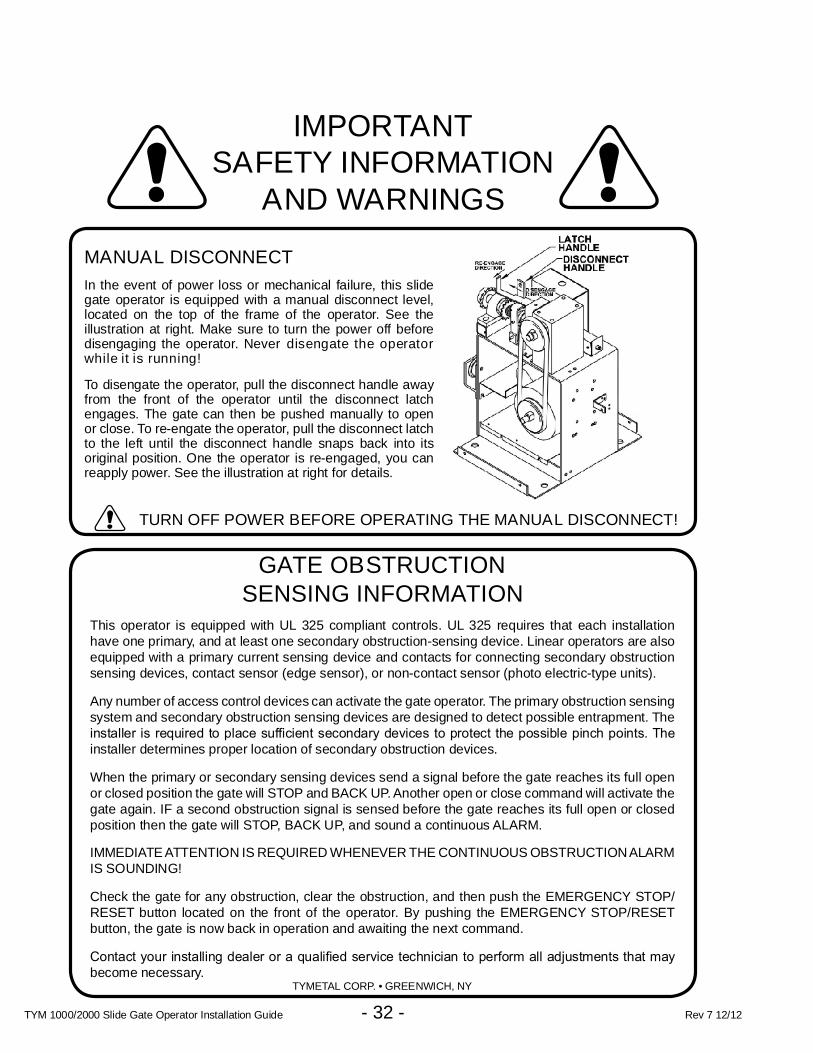
MANUAL DISCONNECT
In the event of power loss or mechanical failure, this slidegate operator is equipped with a manual disconnect level,located on the top of the frame of the operator. See theillustration at right. Make sure to turn the power off beforedisengaging the operator. Never disengate the operatorwhile it is running!
To disengate the operator, pull the disconnect handle awayfrom the front of the operator until the disconnect latchengages. The gate can then be pushed manually to openor close. To re-engate the operator, pull the disconnect latchto the left until the disconnect handle snaps back into itsoriginal position. One the operator is re-engaged, you canreapply power. See the illustration at right for details.
TURN OFF POWER BEFORE OPERATING THE MANUAL DISCONNECT!
GATE OBSTRUCTIONSENSING INFORMATION
This operator is equipped with UL 325 compliant controls. UL 325 requires that each installationhave one primary, and at least one secondary obstruction-sensing device. Linear operators are alsoequipped with a primary current sensing device and contacts for connecting secondary obstructionsensing devices, contact sensor (edge sensor), or non-contact sensor (photo electric-type units).
Any number of access control devices can activate the gate operator. The primary obstruction sensingsystem and secondary obstruction sensing devices are designed to detect possible entrapment. Theinstaller is required to place suffi cient secondary devices to protect the possible pinch points. The installer determines proper location of secondary obstruction devices.
When the primary or secondary sensing devices send a signal before the gate reaches its full openor closed position the gate will STOP and BACK UP. Another open or close command will activate thegate again. IF a second obstruction signal is sensed before the gate reaches its full open or closedposition then the gate will STOP, BACK UP, and sound a continuous ALARM.
IMMEDIATE ATTENTION IS REQUIRED WHENEVER THE CONTINUOUS OBSTRUCTIONALARMIS SOUNDING!
Check the gate for any obstruction, clear the obstruction, and then push the EMERGENCY STOP/RESET button located on the front of the operator. By pushing the EMERGENCY STOP/RESETbutton, the gate is now back in operation and awaiting the next command.
Contact your installing dealer or a qualifi ed service technician to perform all adjustments that may become necessary.
TYMETAL CORP. • GREENWICH, NY

TYM 1000/2000 Slide Gate Operator Installation Guide - 33 - Rev 7 12/12
TYM 1000/2000 Exploded View

TYM 1000/2000 Slide Gate Operator Installation Guide - 34 - Rev 7 12/12
TYM 1000/2000 MECHANICAL PARTS LIST
REF. # PART # DESCRIPTION1 2300-907 Operator Cover
1A2510-354 Plunger Reset Assembly2500-2240 Plunger Reset Button2500-2241 Plunger Extension Only
1B2200-790 Lock for Cover, with Keys2200-824 Extra Keys
2 2110-796 Main Frame Assembly3 2100-2055 Bottom Shelf4 2100-1985 Pillow Block Tube Spacer7 2200-954 Gear Reducer, 20:1
7A2500-2481 Heater, Immersion, 115 VAC, 20W111059 Thermostat, Heater, 40/60 (not shown)
8 2110-777 Reducer Coupler, with Oilite Bushing10 2100-2026 Disconnect Collar11 2200-115 Disconnect Collar Spring12 2200-014 Shaft Collar, 1” diameter, 3/8” LTB13 2100-1983 Drive Shaft, 1” diameter
13A 2100-529 1” Woodruff Key14 2100-1986 Disconnect Handle Fulcrum Bracket
152100-549 Pin for Disconnect Handle2400-169 Push-on Nut, 1/4” (not shown)
16 2120-477 Disconnect Handle17 2100-2060 Disconnect Fulcrum Bracket18 2100-2059 Disconnect Lever19 2200-939 Locking Handle Spring20 2200-274 Pillow Block Bearing, 1” diameter21 2200-042 Sprocket, 48-B-15, 1” bore
2200-276 Sprocket, 48-B-20, 1/2” bore(For drives 34 to 47 feet wide)
2200-855#48 Roller Chain, 16 Links(Use with 2200-276 Sprocket)
2200-010 #48 Master Link
24
2500-2393 APeX Module2100-2104 APeX Mounting Plate2300-1025 Plastic Cover2510-423 Knob Kit
25
2520-396-SLC Limit Box Assembly with Cover2100-057 Limit Shaft2200-029 Oilite Bushing2200-030 Limit Nut2200-193 1/2” E-ring2300-946 Heyco Bushing with Wire Guards2500-2347 Limit Switch2500-764 Auxiliary Limit Switch (not included)2100-261 Detent Plate2200-028 Detent Spring
26 2300-945 Limit Box Cover
REF. # PART # DESCRIPTIONMOTORS
272500-2307 1/2 HP, 115 VAC, 1 Phase2500-2312 1 HP, 208/230 VAC, 1 Phase
CAPACITORS
282500-2336 Capacitor for 2500-2307 Motor2500-1932 Capacitor for 2500-2312 Motor
29 2200-118 4” Pulley, 5/8” bore30 2200-955 4” Pulley, 3/4” bore31 2200-961 V-belt, 4L 35”32 2500-2435 Alarm33 2100-2114 Stop/Reset Button Bracket34 2500-1495 Stop/Reset Button35 2200-650 Sprocket, 41-B-24, 1” bore
36
2110-823 Idler Assembly2300-697 Idler Wheel, UHMW2400-527 3/4” Shoulder Bolt2400-528 5/8” Lock Washer2400-529 5/8” - 11 Nut
37 2100-2109 APeX Controller Mounting Bracket (not shown)
38
2510-422 115 VAC Power Box Assembly2510-430 230 VAC Power Box Assembly2500-2411 Power Switch2500-2413 Power Outlet (only available on 115 VAC Models)2500-212 115 VAC - 24 VAC Power Transformer2500-791 230 VAC - 24 VAC Power Transformer2100-2113 Back Plate2100-2112 Cover Plate
392510-424 115 VAC Wiring Harness Assembly (not shown)2510-428 230 VAC Wiring Harness Assembly (not shown)
402500-2029 Box, Junction2500-2224 Cover, Juction Box
41 2100-2098 Back Plate42 2100-2010 Base Plate43 2400-501 1” Rotor Clip

TYM 1000/2000 Slide Gate Operator Installation Guide - 35 - Rev 7 12/12
Preventative Maintenance
General
Tymetal Corp. gate operators are designed for manyyears of trouble-free operation and, under recommendedoperating conditions, will require only minimal maintenance.To ensure that a unit is ready for operation at all times, andto preclude serious damage or failure, inspect the unitsystematically. Proper adjustments and lubrication shouldbe made as recommended.
This operator is built for cold climate use and includessynthetic gearbox lube, thermostatically controlled gearboxheater, cogged gearbelt and “critter” protection plates.
Lubrication
3 Bearings — For models which have pillow block stylebearings with grease fi ttings, lubricate at least twice a year with a lithium complex based, petroleum oil NLGI 2rated grease. Oilite and precision sealed bearings do notrequire additional lubrication.
3 Motor — Motors have sealed ball bearings and do notrequire further lubrication. If bearing noise developsafter several years of operation, bearings should bereplaced by a motor repair company, or the motor shouldbe replaced if necessary.
3 Drive Chain and Sprocket — The main drive chain andsprockets should be inspected for wear, cleaned, andwiped down with a lightly oiled rag every six months.Lubricate with general purpose spray chain and cablelube.
6-Month Preventative Maintenance
1. Inspect V-belts for wear and replace as necessary. Checkfor proper tension and adjust if required. Check all pulleysetscrews for tightness and tighten if necessary.
2. Inspect chain and sprockets for wear and replace ifnecessary. Check for proper tension and alignment, andadjust if required.
3. Check limit switches and limit actuators (cams, limitnuts, etc.) for wear and replace as required.
4. Inspect the installation area. Are all the warning signsintact and visible? If they are missing or need replacing,contact Tymetal Corp. Be sure there are no controlstations mounted within reach of the gate. Review safetyliterature with the customer and advise them to removeany such stations found.
5. Inspect disconnect handle for proper function andlubricate if necessary. Use a lithium based grease on allmoving parts.
6. Inspect all nuts and bolts for proper tightness and tightenas necessary.
7. Check all reversing devices for proper function. Inspectall contact edges for wear and replace if required. Checkphotoeyes for proper alignment and function.
8. Check current sensing for proper adjustment whenfi nished with inspection and maintenance.
FCC Notice
This device complies with FCC Rules Part 15 and IndustryCanada Rules & Regulations. Operation is subject to thefollowing two conditions: (1) This device may not causeharmful interference and (2) this device must accept anyinterference received, including interference that may causeundesired operation.
WARNINGAlways disconnect power from operator beforeservicing. Keep clear of gate during operation.
For all gate operators, you must inspect the gate for properoperation. The gate should move easily without binding throughits entire travel. If the gate does bind, adjust or fi x as required. Failure to keep the gate in good working condition will haveadverse effects on the operator.

TYM 1000/2000 Slide Gate Operator Installation Guide - 36 - Rev 7 12/12
Gate Operator Installation Checklist
___ ___ 1. The gate has been checked to make sure it is level and moves freely in both directions.
___ ___ 2. Potential pinch areas have been guarded so as to be inaccessible OR havecontactand/or non-contact obstruction sensing devices installed.
___ ___ 3. The installer has installed one or more contact or non-contact obstruction sensingdevices, in compliance with UL325 requirements for this installation.
___ ___ 4. If pedestrian traffi c is expected, a separate pedestrian gate has been installed, a minimum of seven feet from the gate. The customer has beeninformed that all pedestrian traffi c must use the pedestrian gate.
___ ___ 5. Warning signs have been installed on each side of the gate in highly visible locations.The customer has been informed that these signs must remain at all times.
___ ___ 6. There are no controls installed on the gate operator, or within seven feet of the gate.
___ ___ 7. The installer has properly adjusted the obstruction sensing feature and has tested the gateto make sure that the gate stops and reverses a short distance with minimal resistanceapplied (40 lbs. on a swing gate at the end of the gate, 75 lbs. on a slide gate)
___ ___ 8. The installer has instructed the customer in the proper use of the gate operator and reviewedall of the operational functions, obstruction sensing devices, warning beeper and reset, etc.
___ ___ 9. The installer has instructed the customer in the proper use of the operator’smanual disconnect feature. The manual disconnect must never be usedwhile the gate is in motion. The power switch must be turned off beforeusing the manual disconnect and disengaging the operator.
___ ___ 10. The installer has reviewed all safety instructions with the customer, and has leftthe safety instructions and owner’s information sheets for their reference.
___ ___ 11. The installer has answered any questions the customer has regarding theoperation of the gate operator and gate operator safety precautions.
___ ___ 12. The installer has explained to the customer that a regular maintenanceschedule for both the gate and the gate operator is recommended.
By signing this installation checklist, I/we hereby certify that each item listed and checked above has been covered by theinstaller and is clearly understood by the customer.
INSTALLER CUSTOMER
Customer’s Signature
Installer’s Signature
Date
Date