ty91/ty92 vhf radio installation manual - trig avionics ty9x installation... · ty91/ty92 vhf radio...
TRANSCRIPT

TY91/TY92 VHF radio
Installation Manual
00839-00-AF 24 November 2014
Trig Avionics Limited Heriot Watt Research Park Riccarton, Edinburgh EH14 4AP Scotland, UK
Copyright Trig Avionics Limited 2013, 2014

This page intentionally left blank

TY91/TY92 VHF Radio Installation Manual 24 November 2014
00839-00 Issue AF
______________________
Trig Avionics Limited i
CONTENTS
1. PREFACE ...............................................................................................6
1.1 PURPOSE ...........................................................................................6
1.2 SCOPE ...............................................................................................6
1.3 CHANGES FROM PREVIOUS ISSUE ......................................................6
1.4 DOCUMENT CROSS-REFERENCES ......................................................7
2. INTRODUCTION ..................................................................................8
2.1 TY91/TY92 DESCRIPTION ................................................................8
2.2 INTERFACES ......................................................................................9
2.2.1 TY91/TY92 VHF radio Unit .....................................................9
2.2.2 TC90 Controller Unit ...............................................................9
3. TECHNICAL SPECIFICATIONS .....................................................11
3.1 TY91 VHF RADIO UNIT (00882-00-01) .........................................11
3.2 TY92 VHF RADIO UNIT (00879-00-01) .........................................12
3.3 TC90 CONTROL UNIT (00857-00-01) .............................................14
3.4 LOW VOLTAGE OPERATION ............................................................14
3.5 INSTALLATION APPROVAL ...............................................................15
4. UNIT AND ACCESSORIES SUPPLIED...........................................16
4.1 TY91 VHF RADIO ITEMS ................................................................16
4.2 TY92 VHF RADIO ITEMS ................................................................16
4.3 TC90 CONTROLLER ITEMS ..............................................................16
4.4 TY91/TY92 INSTALLATION KIT .....................................................17
4.5 TC90 INSTALLATION KIT ................................................................17

TY91/TY92 VHF Radio Installation Manual 24 November 2014
00839-00 Issue AF
______________________
ii Trig Avionics Limited
4.6 REQUIRED ITEMS ............................................................................17
5. INSTALLATION .................................................................................19
5.1 UNPACKING AND INSPECTING EQUIPMENT ......................................19
5.2 TC90 CONTROLLER MOUNTING ......................................................19
5.2.1 Dual TC90 Considerations ....................................................20
5.3 VHF RADIO MAIN UNIT MOUNTING ...............................................20
5.4 COOLING REQUIREMENTS ...............................................................21
5.5 TY91/TY92 VHF RADIO ELECTRICAL CONNECTIONS ....................21
5.5.1 TY91/TY92 Interface – Pinout ................................................21
5.6 TY91/TY92 VHF RADIO INTERFACE DETAILS ...............................23
5.6.1 Speaker Output .......................................................................23
5.6.2 TMAP Bus ..............................................................................23
5.6.3 Headphone Output .................................................................23
5.6.4 Controller Power ...................................................................23
5.6.5 Power On ...............................................................................24
5.6.6 PTT1/2 Key Input ...................................................................24
5.6.7 Intercom Key Input .................................................................24
5.6.8 Transmit Interlock ..................................................................24
5.6.9 Auxiliary Audio Input .............................................................25
5.6.10 Microphone Input ...................................................................25
5.6.11 Power Input ............................................................................26
5.6.12 Ground Returns ......................................................................26
5.7 TC90 CONTROLLER ELECTRICAL CONNECTIONS ............................26
5.7.1 TC90 Interface - Pinout .........................................................26

TY91/TY92 VHF Radio Installation Manual 24 November 2014
00839-00 Issue AF
______________________
Trig Avionics Limited iii
5.8 TC90 CONTROLLER INTERFACE DETAILS .......................................27
5.8.1 TMAP Bus ..............................................................................27
5.8.2 RS232 Input ............................................................................28
5.8.3 Remote ON .............................................................................28
5.8.4 Power .....................................................................................28
5.8.5 Step Button .............................................................................28
5.8.6 Transfer Button ......................................................................29
5.9 D CONNECTOR CRIMP TERMINALS .................................................29
5.10 WIRING CONSIDERATIONS ...............................................................30
5.10.1 TC90 Interconnect ..................................................................30
5.10.2 Dual TC90 Interconnect .........................................................31
5.10.3 Audio wiring ...........................................................................33
5.11 ANTENNA INSTALLATION ................................................................33
5.11.1 Antenna Ground Plane...........................................................34
5.11.2 Antenna Cable ........................................................................34
5.11.3 TNC Connector ......................................................................35
6. INSTALLATION SETUP AND TEST ...............................................37
6.1 INITIAL POWER ON ..........................................................................37
6.2 CONFIGURATION ITEMS ...................................................................37
6.2.1 Intercom Volume ....................................................................38
6.2.2 Intercom Squelch....................................................................38
6.2.3 Auxiliary Input Volume ..........................................................38
6.2.4 Auxiliary Input Muting ...........................................................38
6.2.5 Sidetone Volume .....................................................................38

TY91/TY92 VHF Radio Installation Manual 24 November 2014
00839-00 Issue AF
______________________
iv Trig Avionics Limited
6.2.6 Radio Squelch Offset ..............................................................39
6.2.7 Frequency Step Size ...............................................................39
6.2.8 Display Brightness .................................................................39
6.2.9 Microphone Sensitivity Adjustment ........................................39
7. POST INSTALLATION CHECKS ....................................................41
8. NORMAL OPERATION ....................................................................42
8.1 OVERVIEW ......................................................................................42
8.2 DISPLAY ..........................................................................................42
8.3 ON/OFF VOLUME KNOB ..................................................................42
8.4 TUNING KNOBS ...............................................................................43
8.5 FLIP-FLOP BUTTON ..........................................................................43
8.6 MON BUTTON ................................................................................43
8.7 MEM BUTTON ................................................................................43
8.8 DUAL CONTROL OPERATION ...........................................................44
8.9 DUAL CONTROL INDIVIDUAL FUNCTIONS........................................44
8.10 GENERAL LOW TEMPERATURE OPERATION ....................................45
8.11 WARNING MESSAGES......................................................................45
8.12 FAULT ANNUNCIATION ...................................................................45
9. CONTINUED AIRWORTHINESS ....................................................47
9.1 CLEANING THE TC90 CONTROLLER ................................................47
10. LIMITED WARRANTY .................................................................48
11. ENVIRONMENTAL QUALIFICATION FORMS ......................49
12. INSTALLATION DRAWINGS ......................................................55

TY91/TY92 VHF Radio Installation Manual 24 November 2014
00839-00 Issue AF
______________________
Trig Avionics Limited v
12.1 MOUNTING TRAY FIXING AND OVERALL DIMENSIONS ......................55
12.2 FRONT PANEL CONTROLLER DIMENSIONS ......................................56
12.3 FRONT PANEL CUT-OUT OPTIONS ...................................................57
13. WIRING DIAGRAMS .....................................................................59

TY91/TY92 VHF Radio Installation Manual 24 November 2014
00839-00 Issue AF
______________________
6 Trig Avionics Limited
1. Preface
1.1 Purpose
This manual describes the physical and electrical characteristics and the
installation requirements for a TY91/TY92 VHF radio and associated
controller.
1.2 Scope
This document applies to the installation of the TY91 and TY92 VHF radio.
This manual applies to TY91/TY92 software version 1.5 or later and TC90
controller software version 1.4 or later. The software versions and FPGA are
subject to change without notice.
1.3 Changes from Previous Issue
Changes from Issue AE to Issue AF are:
2.1 Additional description of a dual TC90 installation
2.2 TC90 interface table updated
Section 4 New part numbers and tables added
Section 5 Additional installation information included for dual TC90
installations
5.6.10 Statement added to address dynamic microphone
connections
Section 6 Additional installation information included for dual TC90
installations
Section 8 Dual TC90 operation information included
Section 11 Environmental tables updated to correct the lightning
induced transient susceptibility category from “B2H22” to
“B2H2L2”
TY91/TY92 VHF Radio Installation Manual 24 November 2014
00839-00 Issue AF
______________________
Trig Avionics Limited 7
Section 13 Additional wiring diagrams to include dual TC90
installation
Various The phrase “receiver squelch” changed to “radio squelch”
to show consistency between installation and operation
manuals
1.4 Document Cross-References
00840-00 TY91 VHF radio Operating Manual AD
ETSO 2C169a VHF Radio communication receiving equipment
operating within the radio frequency range
117.875 – 137 MHz
EASA
TSO C169a Minimum Operational Performance standards for
Airborne Radio Communications equipment
standards
FAA
ETSO 2C128 Devices that prevent blocked channels used in
two-way radio communications due to
unintentional transmissions
EASA
TSO C128a Equipment that prevents blocked channels used in
two-way radio communications due to
unintentional transmissions
FAA

TY91/TY92 VHF Radio Installation Manual 24 November 2014
00839-00 Issue AF
______________________
8 Trig Avionics Limited
2. Introduction
2.1 TY91/TY92 Description
The TY91/TY92 VHF radio system is an ED-23C compliant class C (25 kHz
offset carrier) and class E (8.33 kHz single carrier) VHF radio. The TY91 has
a nominal power output of 6 watts, and meets the power output requirements
for Class 4 and Class 6. The TY92 has a nominal power output of 16 watts,
and meets the power output requirements for Class 3 and Class 5. The
TY91/TY92 is certified to ETSO 2C169a 2C128a, TSO C169a and TSO
C128a.
The TY91 runs from either a 14 volt nominal or 28 volt nominal DC power
supply with no configuration changes required. The TY92 requires a 28 volt
nominal supply.
The TY91 and TY92 VHF radios are controlled using a separate front panel
controller, called the TC90. This allows the radio to be mounted separately
from the instrument panel, and reduces the amount of panel space taken by the
VHF radio. The TC90 is certified to ETSO 2C169a, and TSO C169a.
A single TY91 or TY92 VHF radio can also be controlled with two TC90
controllers. Either control head can tune the radio or adjust the receiver
settings.
Most settings altered on one TC90 control head are also automatically updated
on the second control head with the exception of the following which only
affect a single controller:
Push/Step frequency step size change.
Screen brightness
Frequencies stored in within the memory.

TY91/TY92 VHF Radio Installation Manual 24 November 2014
00839-00 Issue AF
______________________
Trig Avionics Limited 9
2.2 Interfaces
2.2.1 TY91/TY92 VHF radio Unit
The main VHF radio unit has a single TNC antenna connection and a single 25
way D-type connector. The 25 way D-type interface provides the following
services:
Power Input The TY91 operates on 11 to 33 volts DC. The TY92
operates on 22 to 33 volts DC.
Front Panel Datalink A two wire data link is used to connect the TY91/TY92
and the controller.
Front Panel Power The controller is powered from the VHF radio.
Remote On/Off The on-off switch is on the TC90 controller(s), and uses
this input to turn the radio on or off.
Microphone inputs There are two microphone inputs, suitable for
conventional aircraft microphones.
Push-to-talk inputs There are two push to talk inputs corresponding to the two
microphones.
Headphone output A headphone output suitable for conventional aircraft
headsets with impedance in the region of 150 ohms.
Speaker output A speaker output suitable for a cabin speaker with
impedance of 4 ohms or greater.
Intercom keyswitch An optional input to allow the intercom to be switch
controlled.
Auxiliary audio
input
A single connection to allow audio annunciators or ident
tones to be routed to the headphones and speaker.
2.2.2 TC90 Controller Unit
The TC90 controller has a single 15 way D-type connector. It provides the
following services:

TY91/TY92 VHF Radio Installation Manual 24 November 2014
00839-00 Issue AF
______________________
10 Trig Avionics Limited
Power Input The controller receives power from the VHF radio.
Front Panel Datalink A two wire data link is used to connect the
TY91/TY92 and the controller. On a dual control
installation this connects between both controllers and
the TY91/TY92
Remote On/Off The on-off switching is on the controller, and controls
this output.
External switch
inputs
Optional keyswitch inputs to enable remote transfer
and frequency stepping
Serial input Optional input to allow preloading of frequencies,
generally from a GPS. On a dual TC90 installation the
loaded frequencies appear only the TC90 that is
connected to the GPS.

TY91/TY92 VHF Radio Installation Manual 24 November 2014
00839-00 Issue AF
______________________
Trig Avionics Limited 11
3. Technical Specifications
3.1 TY91 VHF Radio Unit (00882-00-01)
Specification Characteristics
Compliance ETSO 2C169a Class C, E, H1, H2, 4, 6, ETSO
2C128, TSO C169a Class C, E, 4, 6, TSO
C128a
FCC Identification VZI00882
Applicable documents EUROCAE ED-23C, EUROCAE ED-67,
EUROCAE ED-14F (RTCA DO-160F),
RTCA DO-186B, RTCA DO-207
Software ED-12B (RTCA DO-178B) Level B
Hardware DO-254 Level C
Power Requirements 11 – 33 volts DC. Typical 2.8 watts @ 14volts,
receive; typical 28 watts @ 14 volts, transmit.
Maximum current 3.2A.
Altitude 55,000 feet
Humidity 95% @ +50°C for 6 hours; 85% @ +38°C for
16 hours.
Tested to Category A in DO-160F
Operating Temperature -20°C to +70°C
Transmitter Frequency 118.000 MHz to 136.992 MHz; 760 channels
at 25 kHz spacing, 2280 channels at 8.33 kHz
spacing.
Transmitter Power 6 watts nominal carrier power
Transmitter Modulation 5K6 A3E

TY91/TY92 VHF Radio Installation Manual 24 November 2014
00839-00 Issue AF
______________________
12 Trig Avionics Limited
Stuck-mic timeout 35 seconds
Transmitter Duty Cycle 100% transmit is possible (subject to stuck mic
timeout)
Receiver Frequency 118.000 MHz to 136.992 MHz; 760 channels
at 25 kHz spacing, 2280 channels at 8.33 kHz
spacing.
Receiver Sensitivity < 5uV for 6 dB SINAD
AGC Characteristic < 6dB variation 5 uV to 100 mV EMF
Physical Specifications (in the mounting tray)
Height 48mm (1.9”)
Width 66mm (2.5”)
Length 160mm (6.3”)
Weight 0.77lbs. (350 g)
3.2 TY92 VHF Radio Unit (00879-00-01)
Specification Characteristics
Compliance ETSO 2C169a Class C, E, H1, H2, 3, 5, ETSO
2C128, TSO C169a Class C, E, 3, 5, TSO
C128a
FCC Identification VZI00879
Applicable documents EUROCAE ED-23C, EUROCAE ED-67,
EUROCAE ED-14F (RTCA DO-160F),
RTCA DO-186B, RTCA DO-207
Software ED-12B (RTCA DO-178B) Level B
Hardware DO-254 Level C

TY91/TY92 VHF Radio Installation Manual 24 November 2014
00839-00 Issue AF
______________________
Trig Avionics Limited 13
Power Requirements 22 – 33 volts DC. Typical 2.8 watts @ 28volts,
receive; typical 80 watts @ 28 volts, transmit.
Maximum current 3.2A.
Altitude 55,000 feet
Humidity 95% @ +50°C for 6 hours; 85% @ +38°C for
16 hours.
Tested to Category A in DO-160F
Operating Temperature -20°C to +55°C
Transmitter Frequency 118.000 MHz to 136.992 MHz; 760 channels
at 25 kHz spacing, 2280 channels at 8.33 kHz
spacing.
Transmitter Power 16 watts nominal carrier power
Transmitter Modulation 5K6 A3E
Stuck-mic timeout 35 seconds
Transmitter Duty Cycle 50% duty cycle – 35 seconds on followed by 35
seconds off.
Receiver Frequency 118.000 MHz to 136.992 MHz; 760 channels
at 25 kHz spacing, 2280 channels at 8.33 kHz
spacing.
Receiver Sensitivity < 5uV for 6 dB SINAD
AGC Characteristic < 6dB variation 5 uV to 100 mV EMF
Physical Specifications (in the mounting tray)
Height 48mm (1.9”)
Width 66mm (2.5”)
Length 160mm (6.3”)
Weight 0.77lbs. (350 g)

TY91/TY92 VHF Radio Installation Manual 24 November 2014
00839-00 Issue AF
______________________
14 Trig Avionics Limited
3.3 TC90 Control Unit (00857-00-01)
Specification Characteristics
Compliance ETSO 2C169a, TSO C169a
Applicable documents EUROCAE ED-23C, EUROCAE ED-14F (RTCA
DO-160F), RTCA DO-186B
Software ED-12B (RTCA DO-178B) Level B
Altitude 35,000 feet
Humidity 95% @ +50°C for 6 hours; 85% @ +38°C for 16
hours. Tested to Category A in DO-160F
Operating Temperature -20°C to +55°C
Physical Specifications (behind the panel)
Height 44mm (1.8”)
Width 63mm (2.4”)
Length 54mm (2.1”)
Weight 0.11lbs. (90 g)
3.4 Low Voltage Operation
Normal operating voltage for the TY91 is any voltage between 11 and 33 volts,
whilst normal operating voltage for the TY92 is any voltage between 22 and 33
volts. At these voltages all functions behave normally, and transmitter power
meets the applicable Class requirements of ED-23C.
The radio will continue to operate at a lower voltage than these ranges. As the
available voltage falls, the transmitter output power will be reduced, and at 9
volts the nominal transmitter power will be approximately 2.5 watts. The
transmitter will be inhibited below 8 volts.
The receiver also works below the nominal voltage. All receiver functions will

TY91/TY92 VHF Radio Installation Manual 24 November 2014
00839-00 Issue AF
______________________
Trig Avionics Limited 15
work normally, but as a safety feature to preserve battery power in an
emergency, at 10 volts or below the available speaker volume will reduce
significantly.
In addition a warning message, “Low Volts”, will be displayed on the
controller when the bus voltage falls below 10 volts in a TY91, or 18 volts in a
TY92.
3.5 Installation Approval
The conditions and tests required for the TSO approval of the TY91/TY92
VHF radio are minimum performance standards. It is the responsibility of
those installing this VHF radio on or within a specific type or class of aircraft
to determine that the aircraft operating conditions are within the TSO
standards. The VHF radio may be installed only if further evaluation by the
user/installer documents an acceptable installation that is approved by the
appropriate airworthiness authority.

TY91/TY92 VHF Radio Installation Manual 24 November 2014
00839-00 Issue AF
______________________
16 Trig Avionics Limited
4. Unit and Accessories supplied
4.1 TY91 VHF Radio Items
The TY91 VHF radio includes the following items:
Unit Description Qty Part Number
TY91 VHF Radio 1 00882-00-01
TY91/TY92 Mounting Tray 1 00667-00
TY91/TY92 Installation Kit 1 01453-00
4.2 TY92 VHF Radio Items
The TY92 VHF radio includes the following items:
Unit Description Qty Part Number
TY92 VHF radio 1 00879-00-01
TY91/TY92 Mounting Tray 1 00667-00
TY91/TY92 Installation Kit 1 01453-00
4.3 TC90 Controller Items
The TC90 controller includes the following items:
Unit Description Qty Part Number
TC90 VHF Radio Controller 1 00857-00-01
TC90 Installation Kit 1 00864-00
TC90 Mounting Template 1 00817-00

TY91/TY92 VHF Radio Installation Manual 24 November 2014
00839-00 Issue AF
______________________
Trig Avionics Limited 17
4.4 TY91/TY92 Installation Kit
The TY91/TY92 installation kit includes the following items:
Unit Description Qty Part Number
TY91/TY92 VHF Radio Installation
Manual
1 00839-00
TY91/TY92 Pilots Operating Manual 1 00840-00
Connector Co-axial TNC 1 00723-00
Headshell, 25 way 1 00726-00
25 way D-type contact housing (female) 1 00866-00
Crimp Terminal, Female, 22-24 AWG 25 00730-00
4.5 TC90 Installation Kit
The TC90 installation kit includes the following items:
Unit Description Qty Part Number
Mounting adapter (circular hole adapter) 2 00678-00
Headshell, 15 way 1 00867-00
15 way D-type contact housing (female) 1 00865-00
Crimp Terminal, Female, 22-24 AWG 15 00730-00
Long mounting screws, 4-40 thread 4 00736-00
Short mounting screws, 4-40 thread 4 00737-00
4.6 Required Items
Additional items you will require, but which are not in the TY91/TY92
package, include:
Antenna and fixing hardware. The TY91/TY92 is compatible with

TY91/TY92 VHF Radio Installation Manual 24 November 2014
00839-00 Issue AF
______________________
18 Trig Avionics Limited
any standard 50 ohm vertically polarised antenna with a VSWR better
than 2.5:1.
Cables. You need to supply and fabricate all required cables.
Guidance on cable types is given in section 5 below.
Fixings. To secure the VHF radio tray to the airframe you will need
at least 3 flat head screws and three self-locking nuts. If the aircraft
does not have existing mounting provisions you may need to fabricate
additional brackets to support the VHF radio tray.

TY91/TY92 VHF Radio Installation Manual 24 November 2014
00839-00 Issue AF
______________________
Trig Avionics Limited 19
5. Installation
5.1 Unpacking and Inspecting Equipment
Carefully unpack the VHF radio and make a visual inspection of the unit for
evidence of any damage incurred during shipment. If the unit is damaged,
notify the shipping company to file a claim for the damage. To justify your
claim, save the original shipping container and all packaging materials.
5.2 TC90 Controller Mounting
The TC90 VHF radio controller must be mounted rigidly in the aircraft panel.
The controller can be mounted in the ultra compact mounting hole or in a
conventional 57mm (2¼ inch) instrument cut-out.
The following installation procedure should be followed, remembering to allow
adequate space for installation of cables and connectors.
Select a position in the panel that is not too close to any high external
heat source. (The TC90 is not a significant heat source itself and
does not need to be kept away from other devices for this reason).
Don’t forget that on some aircraft the canopy can focus the sun onto
the panel and make the controller very hot.
Avoid sharp bends and placing the cables too near to the aircraft
control cables.
If you are using a 57mm instrument cut-out, you must first clip the two
mounting adapters to the controller. The controller should then be mounted
using the four LONG screws provided.
Note: The mounting adapters are held in place by the clamping
action of the panel installation. As an aid to securing them during
assembly when access is poor, we recommend putting a rubber band
around the adapters and the control head. The rubber band can be
snipped off and discarded when the installation is complete.
If you are using the Trig compact cut-out, you do not need the mounting

TY91/TY92 VHF Radio Installation Manual 24 November 2014
00839-00 Issue AF
______________________
20 Trig Avionics Limited
adapters. The controller should be mounted using the four SHORT screws
provided. The screws supplied are appropriate for panel thicknesses from 3
mm to 5 mm. If a thinner panel is used, you may need to exchange the screws
for shorter versions since they can bottom out in the mounting holes.
If alternate screws are required, please note that the mounting thread in each
case is 4-40.
5.2.1 Dual TC90 Considerations
If you are installing a second TC90 controller then it must also meet the
mounting requirements as stated above.
Both TC90 controllers will need to be wired to the TY91/TY92 remote radio
unit. Consideration should be given to the routing of the additional wires as
this may impact on the overall panel placement of the TC90 controllers.
5.3 VHF Radio Main Unit Mounting
The TY91/TY92 VHF radio is designed to be mounted in any convenient
location in the cockpit, the cabin, or an avionics bay.
The following installation procedure should be followed, remembering to allow
adequate space for installation of cables and connectors.
Select a position in the aircraft that is not too close to any high
external heat source. (The TY91/TY92 can become warm to the
touch itself).
Avoid sharp bends and placing the cables too near to the aircraft
control cables.
Secure the mounting tray (p/n 00667-00) to the aircraft via the three
(3) mounting holes in the tray. The tray should be mounted to a flat
surface - it is important that the tray is supported at the two dimples as
well as the three mounting points.
Put the TY91/TY92 VHF radio into the secured mounting tray by
hooking the connector end under the lip on the tray.
TY91/TY92 VHF Radio Installation Manual 24 November 2014
00839-00 Issue AF
______________________
Trig Avionics Limited 21
Lock the TY91/TY92 VHF radio into the mounting tray by clipping
the retaining wire over the lugs on the opposite end.
5.4 Cooling Requirements
The TY91/TY92 VHF radio meets all applicable ETSO requirements without
forced air-cooling. Reasonable air circulation should be provided.
Attention should be given to the incorporation of cooling provisions to limit
the maximum operating temperature if the TY91/TY92 is installed in close
proximity to other avionics. The reliability of equipment operating in close
proximity in an avionics bay can be degraded if adequate cooling is not
provided.
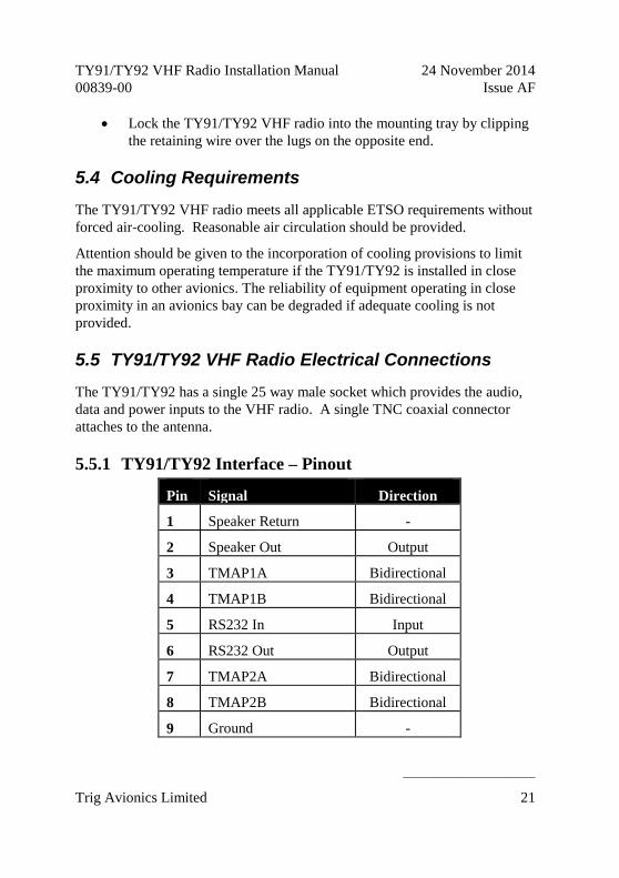
5.5 TY91/TY92 VHF Radio Electrical Connections
The TY91/TY92 has a single 25 way male socket which provides the audio,
data and power inputs to the VHF radio. A single TNC coaxial connector
attaches to the antenna.
5.5.1 TY91/TY92 Interface – Pinout
Pin Signal Direction
1 Speaker Return -
2 Speaker Out Output
3 TMAP1A Bidirectional
4 TMAP1B Bidirectional
5 RS232 In Input
6 RS232 Out Output
7 TMAP2A Bidirectional
8 TMAP2B Bidirectional
9 Ground -

TY91/TY92 VHF Radio Installation Manual 24 November 2014
00839-00 Issue AF
______________________
22 Trig Avionics Limited
10 Headphone Return -
11 Headphone Out Output
12 Controller Power Output
13 Power ON Input
14 PTT2 Key Input
15 PTT1 Key Input
16 Reserved -
17 Intercom Key Input
18 Transmit Interlock Input
19 Ground -
20 Aux Audio Input
21 Microphone 2 Input
22 Ground -
23 Microphone 1 Input
24 Aircraft Power (DC) -
25 Aircraft Power (DC) -
The following diagram shows the connector orientation as viewed from the
wiring side.

TY91/TY92 VHF Radio Installation Manual 24 November 2014
00839-00 Issue AF
______________________
Trig Avionics Limited 23
5.6 TY91/TY92 VHF Radio Interface Details
5.6.1 Speaker Output
The speaker output can drive a 4 ohm or 8 ohm cabin speaker. The speaker
should be rated at 4 watts or higher.
5.6.2 TMAP Bus
TMAP is a Trig proprietary bus based on RS485 signalling. It provides a bi-
directional interface between the VHF radio and the control head. Each TMAP
interface comprises a balanced pair of signals, called A and B, both of which
must be connected for communication to work.
There are two sets of TMAP pins on the TY91/TY92, TMAP1 A and B, and
TMAP2 A and B.
On the TY91 and TY92 TMAP1 and TMAP2 are wired together internally.
The two sets are identical, and either pair (TMAP1 or TMAP2) may be used to
connect to the control head. On a dual control head installation you can attach
one controller to TMAP1 and the other to TMAP2.
5.6.3 Headphone Output
The headphone output is intended to drive one or two sets of 300 to 600 ohm
headphones which may be connected in parallel, or to drive a conventional 600
ohm audio panel input.
5.6.4 Controller Power
The TC90 controller does not connect to aircraft power – it receives power
from the TY91/TY92 using this output. The TY91/TY92 provides 12 volts to
the TC90. This output includes short circuit protection, and no fuse is required
between the TY91/TY92 and the TC90.

TY91/TY92 VHF Radio Installation Manual 24 November 2014
00839-00 Issue AF
______________________
24 Trig Avionics Limited
5.6.5 Power On
The TY91/TY92 power supply is controlled by this discrete input. The input is
active low, so that the TY91/TY92 will power up whenever the input is held
low. This signal is intended to connect to the TC90 Remote ON output.
5.6.6 PTT1/2 Key Input
Two Push to Talk (PTT) inputs are provided, which correspond to the two
microphone inputs. Only the corresponding microphone input is routed to the
transmitter when the key switch is pressed.
The PTT1 input has priority over the PTT2 input – if the PTT1 switch is
closed when the PTT2 switch is closed, the input from Microphone 1 is routed
to the transmitter.
The inputs are active low, and will be asserted when the voltage to ground is
pulled below approximately 4 volts. The input should be connected to a
momentary switch on the yoke or on the microphone.
5.6.7 Intercom Key Input
The intercom key switch input allows the intercom function to be selected
using a remote switch, or permanently enabled by grounding the pin inside the
connector. The input is active low, and will be asserted when the voltage to
ground is pulled below approximately 4 volts.
If this pin is tied low, the intercom function depends on the vox operated
squelch.
Note: It is possible to combine both the key switch and the vox
activation, or to use only one. To use only the switch, wire the switch
to the intercom key input and select the vox squelch to the lowest
setting during configuration. To use only the vox, wire the intercom
key input to ground, and configure the squelch accordingly.
5.6.8 Transmit Interlock
When two VHF radios are mounted in an aircraft the transmit interlock input of

TY91/TY92 VHF Radio Installation Manual 24 November 2014
00839-00 Issue AF
______________________
Trig Avionics Limited 25
one can be connected to the transmit PTT key of the other radio. When the
other radio transmitter is keyed, the squelch threshold of this radio is increased
to minimise break-through between one radio and the other.
Note: To improve the performance when using two radios, the
antennas should be as far apart as practical – for example on the top
and bottom of the fuselage.
5.6.9 Auxiliary Audio Input
This input is continually routed to the headphone and cabin speaker outputs. It
is intended for annunciators and identification tones.
Note: The audio bandwidth on the auxiliary input is limited, and is
not ideal for MP3 players or other entertainment inputs. If such a
device is connected, the mute settings should be enabled in
configuration mode so that radio reception and transmission takes
priority over the music input.
5.6.10 Microphone Input
Microphone connections should be made using shielded twisted pair cables.
The two microphone inputs are identical, and have a nominal sensitivity of 100
mV into a 600 ohm load. A bias voltage is supplied by the radio to the
microphone inputs to support a preamplifier in the microphone.
The TY91/92 has been designed for use with a standard aviation headset and
does not support a directly connected dynamic microphone. Dynamic
microphones are most commonly found in glider installations and will require
an additional preamplifier connected between the microphone and remote radio
unit.
The TY91/92 has a software adjustable preamplifier on the microphone input
which can be used to increase or decrease the microphone input sensitivity.
This can be used to match audio levels between different headset
manufacturers or audio panels.

TY91/TY92 VHF Radio Installation Manual 24 November 2014
00839-00 Issue AF
______________________
26 Trig Avionics Limited
5.6.11 Power Input
The TY91 power supply can be 11-33 volts DC; no voltage adjustment is
required. The TY92 power supply must be 22-33 volts DC. Use a 5 Amp
circuit breaker for power supply protection to the TY91 and TY92.
The peak current consumption on transmit exceeds the current capability of a
single pin on the connector. Both power inputs must be wired, and at least two
ground returns must be wired. This is particularly important when the VHF
radio is mounted on a non-conducting surface, such as a composite structure.
Use 20 AWG wire for the power connection wires.
5.6.12 Ground Returns
There are only 5 ground pins on the 25 way connector, at pins 1, 9, 10, 19 and
22. A full wiring loom with speaker, two headsets, two microphones, the TC90
connection, power and ground requires 9 ground connections. It is therefore
necessary to double up connections to ground pins. This is usually achieved by
bringing a short ground wire from a pin that then acts as a bus point inside the
D shell.
5.7 TC90 Controller Electrical Connections
The TC90 controller has a single 15 way D type male connector to link to the
VHF radio, and optionally to connect to a GPS for loading frequencies of
nearby airfields.
5.7.1 TC90 Interface - Pinout
Pin Signal Direction
1 Ground -
2 TMAPA Bidirectional
3 TMAPB Bidirectional
4 Ground -

TY91/TY92 VHF Radio Installation Manual 24 November 2014
00839-00 Issue AF
______________________
Trig Avionics Limited 27
5 RS232 Tx Output
6 RS232 Rx Input
7 Ground -
8 Remote ON Output
9 Power IN Input
10 Power Ground -
11 Reserved -
12 Step Button Input
13 Transfer Button Input
14 Reserved -
15 Reserved -
The following diagram shows the connector orientation as viewed from the
wiring side.
5.8 TC90 Controller Interface Details
5.8.1 TMAP Bus
TMAP is a Trig proprietary bus based on RS485 signalling. It provides a bi-
directional interface between the VHF radio and the control head. Each TMAP
interface comprises a balanced pair of signals, called A and B, both of which
must be connected for communication to work.
TMAP A and B lines on the controller should be connected to the
corresponding A and B lines of either TMAP1 or TMAP2 on the TY91/TY92.
1 8
9 15

TY91/TY92 VHF Radio Installation Manual 24 November 2014
00839-00 Issue AF
______________________
28 Trig Avionics Limited
In a dual control head installation, the TMAP lines are bussed between the two
controllers and the radio.
5.8.2 RS232 Input
The RS232 input allows certain GPS receivers to preload the standby and
active frequencies. The TC90 understands the Apollo SL40 protocol
($PMRRC) based on NMEA, at a speed of 9600 bps, and responds to message
types 1, 4, 5 and 6.
In a dual control system only the TC90 that is connected to the GPS will
benefit from this feature, the GPS data is not shared between the TC90 control
heads.
The RS232 output can be used for status monitoring of the radio if required.
5.8.3 Remote ON
This output is connected directly to the Power/Mode switch on the TC90, and
should be connected to the Power ON discrete input of the TY91/TY92.
For dual TC90 installations, the Remote On output of both TC90 controllers
should be connected to the Power ON discrete input of the TY91/TY92.
5.8.4 Power
The TC90 uses a regulated 12 volt supply which is provided by the
TY91/TY92 VHF radio. The 12 volt supply from the TY91/TY92 VHF radio
will power both TC90 controllers in a dual control installation.
This input should NOT be connected to aircraft power; it can be damaged by
the voltage surges on the main power bus.
5.8.5 Step Button
The step button is used to allow remote operation of the radio, and is typically
used in a helicopter. Each time the step input is grounded, the next memorised
frequency is copied to the standby position. The input is active low, and will
be asserted when the voltage to ground is pulled below approximately 4 volts.

TY91/TY92 VHF Radio Installation Manual 24 November 2014
00839-00 Issue AF
______________________
Trig Avionics Limited 29
5.8.6 Transfer Button
The transfer button is used to allow remote activation of the frequency change,
and is typically used in a helicopter. The input is active low, and will be
asserted when the voltage to ground is pulled below approximately 4 volts.
5.9 D Connector Crimp Terminals
The 25 way and 15 way connectors supplied with the TY91/TY92 installation
kit are MIL standard versions of the popular sub miniature D type connector
family, and use individual crimp terminals and a receptacle. The MIL
specification for this family of connectors is MIL-C-24308. We supply crimp
terminals because these are more reliable than soldered connections, and are
easier to assemble in-situ in an aircraft, where soldering is impractical. They
also allow individual wires to be removed and replaced in a receptacle without
replacing the whole connector.
The socket contacts used in the connectors conform to MIL part number
M39029/63-368, and are also suitable for wire gauges from 20 to 24 AWG.
These contacts are widely used in avionics installation, and there are many
tools available on the market that will reliably crimp them to the wiring.
Because the contacts are a MIL standard, there is also a MIL standard for the
crimp tool, although other proprietary solutions are also available.
The MIL reference for the basic style of hand tool is M22520/2-01. This style
of tool can crimp many different contact types, and relies on interchangeable
"positioners" to hold the actual contact in use. The MIL reference for the
positioner that you need for the crimps we supply is M22520/2-08.
Any tool that complies with these references can be used to crimp these
contacts. One of the most popular vendors of these small hand tools is Daniels
Manufacturing Corporation (see www.dmctools.com). Their AFM8 hand tool
complies with M22520/2-01, and their K13-1 positioner is M22520/2-08
compliant, so the combination will crimp the supplied connectors.
Once crimped, the contacts should be slotted into the rear of the connector
shell. Push the contact in until the retaining tab clicks into place. Tug gently
to confirm the contact is locked in place.

TY91/TY92 VHF Radio Installation Manual 24 November 2014
00839-00 Issue AF
______________________
30 Trig Avionics Limited
5.10 Wiring Considerations
5.10.1 TC90 Interconnect
The connection from the TY91/TY92 VHF radio to the TC90 uses a minimum
of six (6) signal lines; the TMAP pair, the Power and Ground pair, and the
Remote On discrete line plus associated ground line. In a certified installation
the normal wire choice would be Tefzel hook-up wire. Wire of 20 AWG is
more than adequate for the task; in installations where weight is an issue, wire
of 22 or 24 AWG can also be used. Where lighter wires than 20 AWG are
used the individual wires should be laced together for support.
The TY91/TY92/TC90 interface was tested and certified using unshielded,
untwisted wiring, and that is sufficient for a certified installation. There may
however be technical benefits of improved electromagnetic emissions and
susceptibility to and from the VHF radio system if the two wires of the TMAP
pair are lightly twisted together – one twist per 1 to 2 inches is appropriate.
This may reduce interference and break-through on adjacent audio wiring if it
is not possible to route them separately. For tidiness and consistency the other
pairs in the bundle can also be twisted, but there will be no particular
difference in behaviour.
The distance between the TY91/TY92 VHF radio and the TC90 controller is
limited by the impedance of the wire between them. The TC90 is powered
from the TY91/TY92, not from aircraft power, and therefore the acceptable
voltage drop in the power line is what limits the distance.
The TC90 needs an impedance of less than 1 ohm in the power line for
satisfactory operation. The following table gives guidelines for typical aircraft
hook-up wire. Note that different brands may vary – check your supplier for
details.
Gauge Ohm/km Length for 1 Ohm
20 AWG 35 28.4 m
22 AWG 64 15.6 m
24 AWG 99 10.0 m

TY91/TY92 VHF Radio Installation Manual 24 November 2014
00839-00 Issue AF
______________________
Trig Avionics Limited 31
An alternative to a harness built from individual wires, particularly for a long
cable run, is to use a multi-core cable. Aviation grade cable with 6 or more
cores is often more expensive than the individual wires, and therefore is not
generally a good choice for a certified aircraft. For aircraft where those
considerations do not apply however, an attractive alternative solution may be
to use 3 pair or 4 pair data cable.
Whilst appropriate cables may exist, please note that not all data cable is
suitable for this application. Cables with solid cores should not be used, and
cables should be selected based on the wear characteristics of their insulation
material, including temperature rating, resistance to solvents and oils, and
flammability. Most inexpensive commercial data cables have poor
flammability properties.
Note: If you are installing more than one Trig TY91/TY92 radio, or
installing a radio with a Trig TT21/TT22 transponder, then bundling
the TC90 and TC20 control head interconnecting wires into one loom
is acceptable and will not cause any interference between the two
units. The same is not true of the audio wiring or antenna wiring –
these should be kept apart using normal wiring practices.
5.10.2 Dual TC90 Interconnect
The wiring considerations detail in 5.10.1 should be followed when wiring
both controllers. Cable lengths and routing will vary depending on the physical
placement of the two TC90 controllers and the TY91/92 VHF radio and you
should take this into account when choosing the wire type and size.
On some of the TY91/TY92 connections there is only provision of one output
to feed both TC90 controllers. For these connections, you will need to join or
splice wires together. It is advisable to join the wires at either the TY91/TY92
radio connector or the TC90 connector depending on the physical placement of
the units.

TY91/TY92 VHF Radio Installation Manual 24 November 2014
00839-00 Issue AF
______________________
32 Trig Avionics Limited
Below is an example where the TY91/92 VHF radio is fitted in the nose
section of the aircraft or behind the aircraft panel:
Below is another example where the TY91/92 VHF radio is fitted somewhere
between the front and rear seats:
TY91/TY92
TC90 TC90
Nose Section Front Seat Rear Seat Fuselage Section
1
1
2
2
Only 1 TMAP bus is required to be connected, TMAP1 or TMAP2
Join wires at the TC90 connector end
TY91/TY92
TC90 TC90
Nose Section Front Seat Rear Seat Fuselage Section
1
1
2
2
To reduce the number of wires to be joined, use both TMAP bus
connections on the TY91/TY92 radio. TMAP1 can be used for one
TC90 and TMAP2 for the other.
Join wires at the TY91/TY92 connector end

TY91/TY92 VHF Radio Installation Manual 24 November 2014
00839-00 Issue AF
______________________
Trig Avionics Limited 33
5.10.3 Audio wiring
For any wires carrying an audio signal, a screened twisted pair should be used
to avoid any unwanted signals interfering with the radio installation.
Unscreened wires can act as small antennas and transmissions from other
avionics on the aircraft could be picked up by the radio and heard as
interference in the connected headsets. For example, Mode S transponder
transmissions can be audible as clicking sounds in the headset and cause an
annoying distraction to the pilot.
Correctly terminated screened wiring will limit any unwanted transmissions
being picked up by the radio and should be used on the MIC and PHONE
lines.
5.11 Antenna Installation
The antenna should be installed according to the manufacturer’s instructions.
The following considerations should be taken into account when siting the
Antenna.
The antenna should be well removed from any projections, the
engine(s) and propeller(s). It should also be well removed from
landing gear doors, access doors or others openings which will break
the ground plane for the antenna.
Avoid mounting the antenna within 2 feet of a GPS antenna, and as far
as practical from any ELT antenna.
If the simultaneous use of two radio units is required then each
antenna should be as far apart as practicable for maximum isolation.
We would recommend placing one antenna on top and one on the
bottom of the airframe. The Transmit Interlock function should also
be used in this case (section 5.6.8).
Where practical, plan the antenna location to keep the cable lengths as
short as possible and avoid sharp bends in the cable to minimise the
VSWR.
Electrical connection to the antenna should be protected to avoid loss of
TY91/TY92 VHF Radio Installation Manual 24 November 2014
00839-00 Issue AF
______________________
34 Trig Avionics Limited
efficiency as a result of the presence of liquids or moisture. All antenna feeders
shall be installed in such a way that a minimum of RF energy is radiated inside
the aircraft.
5.11.1 Antenna Ground Plane
When a conventional aircraft monopole antenna is used it relies on a ground
plane for correct behaviour. For ideal performance the ground plane should be
as large as practical; in any case at least 1 metre square. In a metal skinned
aircraft this is usually easy to accomplish, but is more difficult in a composite
or fabric skinned aircraft. In these cases a metallic ground plane should be
fabricated and fitted under the antenna.
The thickness of the material used to construct the ground plane is not critical,
providing it is sufficiently conductive. A variety of proprietary mesh and grid
solutions are available. Heavyweight cooking foil meets the technical
requirements, but obviously needs to be properly supported.
5.11.2 Antenna Cable
Use a high quality 50 ohm coaxial cable, such as RG400 or RG142B.
When routing the cable, ensure that you:
Route the cable away from sources of heat.
Route the cable away from potential interference sources such as
ignition wiring, 400Hz generators, fluorescent lighting and electric
motors.
Allow a minimum separation of 300mm (12 inches) from an ADF
antenna cable.
Keep the cable run as short as possible.
Avoid routing the cable round tight bends.
Avoid kinking the cable even temporarily during installation.
Secure the cable so that it cannot interfere with other systems.

TY91/TY92 VHF Radio Installation Manual 24 November 2014
00839-00 Issue AF
______________________
Trig Avionics Limited 35
5.11.3 TNC Connector
This section describes the technique for attaching the antenna cable to the
supplied TNC connector.
The supplied connector can be completed using a wide range of commercial
crimp tools (for example the Tyco 5-1814800-3). The die apertures for the
inner pin and the outer shield should be approximately 1.72 mm and 5.41 mm
respectively.
Strip back the coax cable to the dimensions in the table, as shown in
the diagram below. Slide 25 mm (1 inch) of heat shrink tubing over
the cable.
Slide the outer crimp sleeve over the cable – it must go on before
securing the centre contact.
Dimension Cut size
(mm)
Cut size
(inches)
A 17.5 0.69
B 7.2 0.28
C 4.8 0.19
Crimp the centre contact to the cable.
Insert the cable into the connector – the centre contact should click
into place in the body, the inner shield should be inside the body of
the connector and the outer shield should be outside the body.
Crimp the outer sleeve over the shield.

TY91/TY92 VHF Radio Installation Manual 24 November 2014
00839-00 Issue AF
______________________
36 Trig Avionics Limited
Slide heat shrink tubing forward (flush to connector) and heat to
shrink the tubing.

TY91/TY92 VHF Radio Installation Manual 24 November 2014
00839-00 Issue AF
______________________
Trig Avionics Limited 37
6. Installation Setup and Test
6.1 Initial Power On
The TC90 will display a splash screen when the radio is first switched on. The
splash screen shows the software versions currently loaded and what model of
radio is connected.
When two TC90 controllers are installed in a dual control setup, either TC90
can power up the radio. To power off the radio, both TC90 controllers must be
turned to the OFF position.
6.2 Configuration Items
There are a small number of installation parameters that can be adjusted.
These parameters are accessed by turning on the radio and then pressing and
holding the MON button for approximately 2 seconds. The individual setup
items can then be selected using the large tuning knob, and adjusted using the
small tuning knob. Pressing MON again will exit from the setup mode.
The script will prompt for the following configuration items:
Intercom Volume
Intercom Squelch
Auxiliary Input Volume
Auxiliary Input Muting
Sidetone Volume
Radio Squelch Offset
Frequency Step Size
Display brightness
The items listed above may be changed in flight, and the configuration mode is
described in the pilot handbook. An additional adjustment, intended for use at

TY91/TY92 VHF Radio Installation Manual 24 November 2014
00839-00 Issue AF
______________________
38 Trig Avionics Limited
installation, is accessed on a sub menu by holding down the MEM button for at
least 3 seconds whilst in configuration mode:
Microphone gain adjustment
In a dual TC90 control setup most of the configuration items are shared and
automatically updated between the TC90 controllers. The Display Brightness
and Frequency Step Size configuration are independently set in the local TC90
controller.
6.2.1 Intercom Volume
This setting controls the volume of the intercom.
6.2.2 Intercom Squelch
The intercom includes a voice activated squelch control to limit the
background noise heard over the intercom. Increasing the squelch level
requires a louder microphone input to gate the intercom.
6.2.3 Auxiliary Input Volume
The auxiliary input is a low-fidelity monophonic input intended for nav radio
ident inputs and simple annunciators. This setting controls the relative volume
of the auxiliary audio input.
6.2.4 Auxiliary Input Muting
This allows the auxiliary input to be muted when the radio is receiving or
transmitting speech. Turn this feature ON if the auxiliary input is being used
for non-essential services, like an MP3 player. Turn this feature OFF if the
auxiliary input is being used for essential services like annunciators or traffic
alerts.
6.2.5 Sidetone Volume
The audio sidetone is the transmitted audio signal; this setting controls the level
of the sidetone in the headphones.

TY91/TY92 VHF Radio Installation Manual 24 November 2014
00839-00 Issue AF
______________________
Trig Avionics Limited 39
6.2.6 Radio Squelch Offset
The receiver has a factory set nominal squelch point of approximately -95 dBm
which should be appropriate for most installations. In some aircraft with noisy
electrical environments, such as vintage or experimental aircraft, the factory
setting may lead to nuisance squelch changes triggered by noise.
The radio squelch offset allows the installer to moderately increase the squelch
set point.
6.2.7 Frequency Step Size
The TY91/TY92 is capable of operating in both an 8.33 kHz and 25 kHz
environment. If 8.33 kHz operation is not required, the 8.33 kHz channels can
be disabled to simplify the tuning operation.
Note: 8.33 kHz operation is required in some European airspace.
Note: On a dual TC90 installation. this setting only affects the
individual TC90 and does not automatically update between the
controllers. In an 8.33 kHz environment, both TC90’s will need to be
correctly configured.
6.2.8 Display Brightness
The TC90 control head display backlighting can be adjusted to suit ambient
light conditions. A bar on the display shows the relative brightness and the
display changes brightness as the small tuning knob is turned.
Note: On a dual TC90 installation, this setting only affects the local
TC90 and allows the user to independently set their brightness
preference.
6.2.9 Microphone Sensitivity Adjustment
Whilst in configuration mode, pressing the MEM button for at least 3 seconds
enables additional menus for adjustment of the microphone gain.
The factory set microphone adjustment provides a nominal sensitivity of 100

TY91/TY92 VHF Radio Installation Manual 24 November 2014
00839-00 Issue AF
______________________
40 Trig Avionics Limited
mV RMS which is compatible with most conventional aviation headset
microphones. Automatic gain control takes care of variations in speaking
voice and variation between different microphones. Microphone adjustment is
therefore only required to correct for alternative installation choices. If the
installation uses unusually high output microphones, or an audio panel with
built-in amplification, the radio input can be overloaded and cause distortion
on the transmitted audio. If the microphone output is too low, the transmitted
modulation will be low, and may be unreadable. Each microphone input can
be adjusted separately.
The microphone gain is adjusted in steps of 1 dB. The left end stop on the
range corresponds to a nominal sensitivity of 200 mV; the right end stop
corresponds to a nominal sensitivity of 6 mV. The factory original setting is 6
steps from the left of the range.
Press the MON button to exit set-up.

TY91/TY92 VHF Radio Installation Manual 24 November 2014
00839-00 Issue AF
______________________
Trig Avionics Limited 41
7. Post Installation Checks
Post installation checks should be carried out in accordance with your
certification requirements. These checks should include:
Receiver operation. Tune a local station and check that the reception
is clear and understandable.
Transmitter operation and microphone gain adjustment. Contact a
local station and check that they are receiving you clearly.
Interference check. Check the radio with other avionics and electrical
equipment on the aircraft operating. Check at low, mid and high radio
frequencies. There should be no significant interference on reception,
and when the TY91/TY92 transmits there should be no adverse effect
on any other equipment.
Sidetone adjustment. During the transmit checks, verify the sidetone
level is set appropriately.
Intercom adjustment. If the intercom function is being used, set the
listening level and squelch appropriately. Note that the squelch is best
adjusted in the normal ambient noise environment, for example with
the engine(s) running and developing power.

TY91/TY92 VHF Radio Installation Manual 24 November 2014
00839-00 Issue AF
______________________
42 Trig Avionics Limited
8. Normal Operation
8.1 Overview
On the front panel is a monochrome LCD display flanked by a rotary volume
knob (OFF, and Squelch function) and a dual concentric tuning knob used for
frequency entry.
8.2 Display
The display shows the active and standby frequencies for the radio, and has
icons to indicate the operating modes.
8.3 On/Off Volume Knob
The left hand knob controls the power to the VHF radio and the audio volume.
Pressing the left hand knob toggles the radio squelch on and off, which can be
used to listen for faint stations, and as a simple audio test.
Monitor Select
On/Off, Volume and Squelch Knob
Primary Frequency
Primary/Standby Flip Flop
Frequency Step Size
Memory Select
Frequency Select Knob
Secondary Frequency

TY91/TY92 VHF Radio Installation Manual 24 November 2014
00839-00 Issue AF
______________________
Trig Avionics Limited 43
8.4 Tuning Knobs
The right hand knobs are used to tune the radio. The large knob adjusts the
MHz portion of the standby frequency, and the smaller knob adjusts the kHz
portion of the standby frequency.
Pressing the end of the small knob changes the channel spacing that the small
knob operates through. If the radio is configured for 8.33 kHz operation, the
steps toggle between 8.33 kHz channels and 25 kHz channels. If the radio is
configured only for 25 kHz operation, the steps toggle between 25 kHz and 50
kHz channels. Changing the step size does not change the behaviour of the
radio, only the tuning knob step size – it helps to quickly tune a frequency.
8.5 Flip-flop Button
The Flip-flop button swaps the frequency in the standby display, at the bottom
of the screen, into the active position, and moves the active frequency to the
standby position.
8.6 MON Button
The TY91/TY92 includes a dual-frequency listen feature; pressing the MON
button toggles this feature on and off.
When the feature is active, a +2 icon appears next to the standby frequency,
and the radio will scan between the active and standby frequencies listening for
transmissions.
This is useful in an aircraft with only a single radio, since it allows you, for
example, to copy the ATIS whilst maintaining a listening watch on the ATC
frequency.
8.7 MEM Button
Behaviour of the MEM button depends on whether you have a GPS connected
that can load frequencies into the TC90. If you do, then pressing the MEM
button allows access to those frequencies. Turning the LARGE knob steps
through the airports for which frequencies have been loaded. Turning the

TY91/TY92 VHF Radio Installation Manual 24 November 2014
00839-00 Issue AF
______________________
44 Trig Avionics Limited
SMALL knob then steps through the individual frequencies for that airport.
After you have stepped through all the loaded airports, or if there is no GPS
attached, the built-in memory of the TC90 is displayed.
The TC90 has nine frequency memories. Each frequency position can be
selected by turning the SMALL tuning knob.
Whether from a GPS or from the onboard memory bank, the selected
frequency is loaded into the standby window. Pressing MEM again leaves the
stored frequency in the standby window. Pressing the Flip-flop button loads
the stored frequency directly into the active channel.
To store a frequency in one of the memory locations it must first be tuned and
active. Press MEM to enter the memory mode in the usual way. Select the
channel you want to overwrite with the tuning knobs. Now press, AND
HOLD, the MEM button for 2 seconds. The current active frequency will be
moved to the selected memory location, overwriting the existing contents.
8.8 Dual Control Operation
If two control heads are installed for a dual control setup then changes made to
one controller will be automatically updated on the second controller. There is
a small time lag between operating one controller and updating the display on
the second controller. This is purely a delay in the display and there is no
delay in the tuning or operation of the TY91/TY92 radio.
The exception is that the radio volume knob works on a “loudest wins” basis.
The radio volume will always correspond to the control head that has the
volume knob set to the highest position. This means that only one of the
controllers needs to be turned up to operate the radio normally, for example
when flying a tandem aircraft solo.
8.9 Dual Control Individual Functions
The following functions are local to the individual control head and will not
automatically update or transfer between two controllers:

TY91/TY92 VHF Radio Installation Manual 24 November 2014
00839-00 Issue AF
______________________
Trig Avionics Limited 45
Frequency Step Size Changing the frequency step size by pressing the
PUSH/STEP button on one controller does not
affect the other controller.
Brightness The brightness is separately adjusted on each
controller.
Memory The frequencies stored in the memory are local to
each controller. The memory data is not
transferred between controllers, although a
frequency selected from the memory will appear
on the screen on the other controller.
8.10 General Low Temperature Operation
The TY91/TY92 is certified to operate correctly down to -20°C, but at low
temperatures the controller display may be impaired. On a cold day you may
need to wait for the cockpit to warm up to ensure normal operation.
8.11 Warning Messages
If the VHF radio detects a problem, the screen will indicate WARNING and a
brief statement of the problem. Depending on the nature of the problem, your
VHF radio may not be working properly. Note the message on the screen and
pass that information to your avionics maintenance organisation.
Warning messages will automatically clear if the problem is corrected. If a
warning persists, it can be manually cleared by pressing the flip-flop button
twice.
8.12 Fault Annunciation
If the VHF radio detects a catastrophic internal failure, the screen will indicate
FAULT and a brief statement of the problem. The controller will not respond
to button or knob inputs, but the radio may still be working on the last settings
prior to the fault indication.
Some FAULT indications can be recovered by switching the VHF radio off

TY91/TY92 VHF Radio Installation Manual 24 November 2014
00839-00 Issue AF
______________________
46 Trig Avionics Limited
and back on again, although in all cases a FAULT code implies that there is a
fault with the VHF radio or the installation. Note the FAULT message shown
on the screen and pass that information to your avionics maintenance
organisation.

TY91/TY92 VHF Radio Installation Manual 24 November 2014
00839-00 Issue AF
______________________
Trig Avionics Limited 47
9. Continued Airworthiness
Other than for periodic functional checks required by the regulations, the
TY91/TY92 VHF radio has been designed and manufactured to allow “on
condition maintenance”. This means that there are no periodic service
requirements necessary to maintain continued airworthiness, and no
maintenance is required until the equipment does not properly perform its
intended function. When service is required, a complete performance test
should be accomplished following any repair action. Repairs should only be
carried out in accordance with Trig Avionics Limited service procedures.
9.1 Cleaning the TC90 controller
The plastic body and switches should be cleaned with a soft cotton cloth
moistened with clean water. The LCD screen should be lightly cleaned with a
lint free cloth taking care not to scratch the surface.

TY91/TY92 VHF Radio Installation Manual 24 November 2014
00839-00 Issue AF
______________________
48 Trig Avionics Limited
10. Limited Warranty
Trig Avionics Limited warrants our products to be free from defects in
materials and workmanship for a period of two (2) years from the date of
installation by an authorised dealer.
This warranty covers repair and/or replacement at our option, of any parts
found to be defective, provided such defects in our opinion are due to faulty
material or workmanship and are not caused by tampering, abuse, or normal
wear.
All warranties are F.O.B.
Trig Avionics Limited
Heriot Watt Research Park
Riccarton, Edinburgh, EH14 4AP
Trig Avionics will not accept or pay for any charges for warranty work
performed outside our factory without prior written consent.
This warranty applies only to products in normal use. It does not apply to units
or circuit boards defective due to improper installation, physical damage,
tampering, lightning or other electrical discharge, units with altered serial
numbers, or units repaired by unauthorised persons or in violation of Trig
Avionics Limited service procedures.
Trig Avionics Limited assumes no responsibility for any consequential losses
of any nature with respect to any products or services sold, rendered, or
delivered.

TY91/TY92 VHF Radio Installation Manual 24 November 2014
00839-00 Issue AF
______________________
Trig Avionics Limited 49
11. Environmental Qualification Forms
Nomenclature: TY91 VHF radio
Part No: 00882-00-01 ETSO: 2C169a
Manufacturer: Trig Avionics Limited
Address: Heriot Watt Research Park, Riccarton, Edinburgh, Scotland, EH14 4AP
Conditions DO-160F
Section
Description of Conducted Tests
Temperature and Altitude 4.0 Equipment tested to Categories A2, C1
Low temperature ground survival
4.5.1 -55°C
Low temperature short-time operating
4.5.1 -40°C
Low temperature operating
4.5.2 -20°C
High temperature operating
4.5.4 +70°C
High temperature short-time operating
4.5.3 +70°C
High temperature ground survival
4.5.3 +85°C
Loss of Cooling 4.5.5 Cooling air not required (+70°C operating without cooling air)
Altitude 4.6.1 55,000 feet
Decompression 4.6.2 8,000 to 55,000 feet in 15 seconds
Overpressure 4.6.3 -15,000 feet
Temperature Variation 5.0 Equipment tested to Category B
Humidity 6.0 Equipment tested to Category A
Operational Shocks 7.2 Equipment tested to Category B
Crash Safety 7.3 Equipment tested to Category B type 5

TY91/TY92 VHF Radio Installation Manual 24 November 2014
00839-00 Issue AF
______________________
50 Trig Avionics Limited
Vibration 8.0 Aircraft zone 2; type 3, 4, 5 to category S level M, type 1 (Helicopters) to category U level G
Explosion 9.0 Equipment identified as Category X – no test required
Waterproofness 10.0 Equipment identified as Category X – no test required
Fluids Susceptibility 11.0 Equipment identified as Category X – no test required
Sand and Dust 12.0 Equipment identified as Category X – no test required
Fungus 13.0 Equipment identified as Category X – no test required
Salt Spray 14.0 Equipment identified as Category X – no test required
Magnetic Effect 15.0 Equipment tested to Category Z, safe distance 1 metre
Power Input 16.0 Equipment tested to Category BX
Voltage Spike 17.0 Equipment tested to Category B
Audio frequency conducted susceptibility
18.0 Equipment tested to Category B
Induced signal susceptibility
19.0 Equipment tested to Category AC
Radio frequency susceptibility
20.0 Equipment tested to Category TT
Radio frequency emission 21.0 Equipment tested to Category B
Lightning induced transient susceptibility
22.0 Equipment tested to Category B2H2L2
Lightning direct effects 23.0 Equipment identified as Category X – no test required
Icing 24.0 Equipment identified as Category X – no test required
Electrostatic Discharge 25.0 Equipment identified as Category X – no test required
Fire, Flammability 26.0 Equipment identified as Category C

TY91/TY92 VHF Radio Installation Manual 24 November 2014
00839-00 Issue AF
______________________
Trig Avionics Limited 51
Nomenclature: TY92 VHF radio
Part No: 00879-00-01 ETSO: 2C169a
Manufacturer: Trig Avionics Limited
Address: Heriot Watt Research Park, Riccarton, Edinburgh, Scotland, EH14 4AP
Conditions DO-160F
Section
Description of Conducted Tests
Temperature and Altitude 4.0 Equipment tested to Categories A2, C1
Low temperature ground survival
4.5.1 -55°C
Low temperature short-time operating
4.5.1 -40°C
Low temperature operating
4.5.2 -20°C
High temperature operating
4.5.4 +55°C
High temperature short-time operating
4.5.3 +70°C
High temperature ground survival
4.5.3 +85°C
Loss of Cooling 4.5.5 Cooling air not required (+55°C operating without cooling air)
Altitude 4.6.1 55,000 feet
Decompression 4.6.2 8,000 to 55,000 feet in 15 seconds
Overpressure 4.6.3 -15,000 feet
Temperature Variation 5.0 Equipment tested to Category C
Humidity 6.0 Equipment tested to Category A
Operational Shocks 7.2 Equipment tested to Category B
Crash Safety 7.3 Equipment tested to Category B type 5
Vibration 8.0 Aircraft zone 2; type 3, 4, 5 to category S level M, type 1 (Helicopters) to category U level G

TY91/TY92 VHF Radio Installation Manual 24 November 2014
00839-00 Issue AF
______________________
52 Trig Avionics Limited
Explosion 9.0 Equipment identified as Category X – no test required
Waterproofness 10.0 Equipment identified as Category X – no test required
Fluids Susceptibility 11.0 Equipment identified as Category X – no test required
Sand and Dust 12.0 Equipment identified as Category X – no test required
Fungus 13.0 Equipment identified as Category X – no test required
Salt Spray 14.0 Equipment identified as Category X – no test required
Magnetic Effect 15.0 Equipment tested to Category Z
Power Input 16.0 Equipment tested to Category BX
Voltage Spike 17.0 Equipment tested to Category B
Audio frequency conducted susceptibility
18.0 Equipment tested to Category B
Induced signal susceptibility
19.0 Equipment tested to Category AC
Radio frequency susceptibility
20.0 Equipment tested to Category TT
Radio frequency emission 21.0 Equipment tested to Category B
Lightning induced transient susceptibility
22.0 Equipment tested to Category B2H2L2
Lightning direct effects 23.0 Equipment identified as Category X – no test required
Icing 24.0 Equipment identified as Category X – no test required
Electrostatic Discharge 25.0 Equipment identified as Category X – no test required
Fire, Flammability 26.0 Equipment identified as Category C

TY91/TY92 VHF Radio Installation Manual 24 November 2014
00839-00 Issue AF
______________________
Trig Avionics Limited 53
Nomenclature TC90 Radio Controller
Part No: 00857-00-01 ETSO: 2C169a
Manufacturer Trig Avionics Limited
Address Heriot Watt Research Park, Riccarton, Edinburgh, Scotland, EH14 4AP
Conditions DO-160F
Section
Description of Conducted Tests
Temperature and Altitude 4.0 Equipment tested to Categories A4, C4
Low temperature ground survival
4.5.1 -55°C
Low temperature short-time operating
4.5.1 -25°C
Low temperature operating
4.5.2 -20°C
High temperature operating
4.5.3 +55°C
High temperature short-time operating
4.5.3 +70°C
High temperature ground survival
4.5.3 +85°C
Loss of Cooling 4.5.5 Cooling air not required (+70°C operating without cooling air)
Altitude 4.6.1 55,000 feet
Decompression 4.6.2 8,000 to 55,000 feet in 15 seconds
Overpressure 4.6.3 -15,000 feet
Temperature Variation 5.0 Equipment tested to Category A
Humidity 6.0 Equipment tested to Category A
Operational Shocks 7.2 Equipment tested to Category B
Crash Safety 7.3 Equipment tested to Category B type 5
Vibration 8.0 Aircraft zone 2; type 3, 4, 5 to category S level M, type 1 (Helicopters) to category U level G

TY91/TY92 VHF Radio Installation Manual 24 November 2014
00839-00 Issue AF
______________________
54 Trig Avionics Limited
Explosion 9.0 Equipment identified as Category X – no test required
Waterproofness 10.0 Equipment tested to Category W (front face only)
Fluids Susceptibility 11.0 Equipment identified as Category X – no test required
Sand and Dust 12.0 Equipment identified as Category X – no test required
Fungus 13.0 Equipment identified as Category X – no test required
Salt Spray 14.0 Equipment identified as Category X – no test required
Magnetic Effect 15.0 Equipment tested to Category Z
Power Input 16.0 Equipment identified as Category X – no test required
Voltage Spike 17.0 Equipment identified as Category X – no test required
Audio frequency conducted susceptibility
18.0 Equipment identified as Category X – no test required
Induced signal susceptibility
19.0 Equipment tested to Category BC
Radio frequency susceptibility
20.0 Equipment tested to Category TT
Radio frequency emission 21.0 Equipment tested to Category M
Lightning induced transient susceptibility
22.0 Equipment tested to Category B2H2L2
Lightning direct effects 23.0 Equipment identified as Category X – no test required
Icing 24.0 Equipment identified as Category X – no test required
Electrostatic Discharge 25.0 Equipment tested to Category A
Fire, Flammability 26.0 Equipment identified as Category C

TY91/TY92 VHF Radio Installation Manual 24 November 2014
00839-00 Issue AF
______________________
Trig Avionics Limited 55
12. Installation Drawings
12.1 Mounting tray fixing and overall dimensions
All dimensions in millimetres

TY91/TY92 VHF Radio Installation Manual 24 November 2014
00839-00 Issue AF
______________________
56 Trig Avionics Limited
12.2 Front Panel Controller Dimensions
Controller shown without the mounting adapters (00678-00) used for 57mm
(2¼ inch) instrument mounting.
All dimensions in millimetres.

TY91/TY92 VHF Radio Installation Manual 24 November 2014
00839-00 Issue AF
______________________
Trig Avionics Limited 57
12.3 Front Panel Cut-out Options
The front panel controller can be fitted to either the compact mounting hole or
a conventional 57mm (2¼ inch) instrument cut-out. The compact mounting is
a truncated 58 mm opening; please note that the mounting screws are NOT in
the same location for the two options.
Note: The following diagram is intended to be to scale, however
variations in the printing process mean that you MUST check all
dimensions before using it as a template.

TY91/TY92 VHF Radio Installation Manual 24 November 2014
00839-00 Issue AF
______________________
58 Trig Avionics Limited
Note: The following diagram is intended to be to scale, however
variations in the printing process mean that you MUST check all
dimensions before using it as a template.
All dimensions in millimetres.

TY91/TY92 VHF Radio Installation Manual 24 November 2014
00839-00 Issue AF
______________________
Trig Avionics Limited Page 59
13. Wiring Diagrams
Diagram 1: System Interface .................................................................................................................................................... 60
Diagram 2: TY91/TY92 Typical Interconnect .............................................................................................................................. 61
Diagram 3: TY91/TY92 Power and TC90 Interconnect ................................................................................................................ 62
Diagram 4: Audio Connections ................................................................................................................................................. 63
Diagram 5: Dual TC90 Interconnect .......................................................................................................................................... 64
Diagram 6: Audio Panel Connections ........................................................................................................................................ 65
Diagram 7: GPS Connection .................................................................................................................................................... 66

TY91/TY92 VHF Radio Installation Manual 24 November 2014
00839-00 Issue AF
______________________
Page 60 Trig Avionics Limited
TY91/TY92 VHF Radio [ 25 Way Connector ]
Diagram 1: System Interface
TC90 #1 Controller
Cabin Speaker
Auxiliary Audio
Pilots PTT or Mic Key switch
Copilots PTT or Mic Key switch
TX Interlock VHF/Com 2 (If installed)
Speaker Out
Aux Input
PTT1
PTT2
Intercom Enable Switched or permanent connection to ground
TMAP 1A
TMAP 1B
Power On
TC90 Power
TMAP 2A
TMAP 2B
Phones Out
TC90 #2 Controller
Remote Flip-Flop
Remote Memory Step
GPS
MIC 1 Input
MIC 2 Input
[ TNC Antenna Connector ]
COM Antenna
Pilot Microphone
Copilot Microphone
Pilot Headphones
Copilot Headphones
Power & Ground Aircraft Power and Ground
1
1 THE TY91/TY92 DOES NOT DIRECTLY SUPPORT DYNAMIC STYLE
MICROPHONES. A PREAMPLIFIER MUST BE CONNECTED BETWEEN THE
MICROPHONE AND RADIO WHEN USING A DYNAMIC MICROPHONE. THE
TY91/92 PROVIDES A 12V DC PHANTOM POWER.

TY91/TY92 VHF Radio Installation Manual 24 November 2014
00839-00 Issue AF
______________________
Trig Avionics Limited Page 61
TC90
Controller
TY
91/T
Y92
VH
F R
adio
Speaker GND
Speaker OUT
TMAP 1A
TMAP 1B
TC90 Power
Power ON
Ground
TMAP 2A
TMAP 2B
TX Interlock
Aux In
Intercom PTT
Reserved
Reserved
Reserved
PTT2
MIC 2 In
Ground
PTT 1
MIC 1 In
Phone Out
Phone Gnd
DC Power
DC Power
Ground
RF
1
2
3
4
12
13
9
7
8
18
20
17
5
6
16
14
21
22
15
23
11
10
24
25
19
Ground
TMAP A
TMAP B
Ground
RS232 Out
RS232 In
Ground
Remote ON
Power In
Ground
Reserved
Step Key
Transfer Key
Reserved
Reserved
1
2
3
4
5
6
7
8
9
10
11
12
13
14
15
PTT 2
PTT1
INTERCOM
PTT
SPEAKER
X
PHONE 2
MIC 2
PHONE 1
MIC 1
REMOTE FREQUENCY
STEP (OPTIONAL)
REMOTE FREQUENCY
TRANSFER (OPTIONAL)
X
X X
4
ANTENNA
5A
(+) AIRCRAFT POWER 11 – 33VDC 20 AWG (NOTE 2)
Diagram 2: TY91/TY92
Typical Interconnect
1
2
3
5
2
3
4
5
DC POWER WIRES SHOULD BE A MINIMUM OF 20 AWG ALL WIRES SHOULD BE 18 – 24 AWG
NOTES:
TMAP LINES 2A AND 2B CONTAIN IDENTICAL DATA AS TMAP 1A
AND 1B. WIRED TOGETHER INTERNALLY
TO PERMANENTLY ENABLE THE INTERCOM THIS SHOULD
CONNECTED DIRECTLY TO GROUND.
AUXILIARY AUDIO INPUT ROUTED TO THE SPEAKER AND
HEADPHONE OUTPUTS
(OPTIONAL) RS232 INPUT FROM GPS TO PRELOAD
STANDBY/ACTIVE FREQUENCIES
MIC CABLES TO BE WIRED USING A TWISTED SCREENED PAIR WITH
THE SCREENING CONNECTED TO GROUND AT THE RADIO END ONLY.
1
2
6
1
6 TX INTERLOCK TO BE CONNECTED WHEN INSTALLING A DUAL
VHF RADIO SYSTEM. REFER TO DIAGRAM 2
(-) AIRCRAFT GROUND
X X
7
7
IF BOTH PTT1 AND PTT2 ARE PRESSED SIMULTANEOUSLY THEN
PTT 1 WILL TAKE PRIORITY AND THEREFORE MIC 1 AUDIO WILL BE
ROUTED TO THE RADIO.
MIC2 KEY LINE
MIC1 KEY LINE
GROUND WIRES CAN BE LOOPED TOGETHER OUTSIDE THE CONNECTOR.
MORE THAN 1 GROUND SHOULD BE PHYSICALLY CONNECTED TO THE
TY91/TY92.
3

TY91/TY92 VHF Radio Installation Manual 24 November 2014
00839-00 Issue AF
______________________
Page 62 Trig Avionics Limited
TC90
Controller
TY
91/T
Y92
VH
F R
adio
Ground
TMAP 1A
TMAP 1B
TMAP 2A
TMAP 2B
Power ON
TC90 Power
Ground
DC Power
DC Power
9
3
4
7
8
13
12
19
24
25
Ground
TMAP A
TMAP B
Ground
RS232 Out
RS232 In
Ground
Remote ON
Power In
Ground
Reserved
Step Key
Transfer Key
Reserved
Reserved
1
2
3
4
5
6
7
8
9
10
11
12
13
14
15
REMOTE FREQUENCY
STEP (OPTIONAL)
REMOTE FREQUENCY
TRANSFER (OPTIONAL)
X
X X
2
5A
(+) AIRCRAFT POWER 11 – 33VDC
20 AWG (NOTE 2)
Diagram 3: TY91/TY92 Power and TC90 Interconnect
1
2
DC POWER WIRES SHOULD BE A MINIMUM OF 20 AWG
ALL WIRES SHOULD BE 18 – 24 AWG
NOTES:
TMAP LINES 2A AND 2B CONTAIN IDENTICAL DATA AS TMAP 1A
AND 1B. WIRED TOGETHER INTERNALLY. THIS MAY BE USED ON
A DUAL TC90 SYSTEM.
(OPTIONAL) RS232 INPUT FROM GPS TO PRELOAD
STANDBY/ACTIVE FREQUENCIES
1
2
1
(-) AIRCRAFT GROUND
GROUND WIRES CAN BE LOOPED TOGETHER OUTSIDE THE CONNECTOR.
MORE THAN 1 GROUND SHOULD BE PHYSICALLY CONNECTED TO THE
TY91/TY92.
3

TY91/TY92 VHF Radio Installation Manual 24 November 2014
00839-00 Issue AF
______________________
Trig Avionics Limited Page 63
TY
91/T
Y92
VH
F R
adio
Speaker GND
Speaker OUT
TX Interlock
Aux In
Intercom PTT
PTT1
MIC 1 In
Ground
PTT2
MIC 2 In
Phone Out
Phone Gnd
1
2
18
20
17
15
23
22
14
21
11
10
PILOT PTT 1
SPEAKER
PHONE 2
MIC 2
PHONE 1
Diagram 4: Audio Connections
2
4
2
4
DC POWER WIRES SHOULD BE A MINIMUM OF 20 AWG
ALL WIRES SHOULD BE 18 – 24 AWG
NOTES:
TO PERMANENTLY ENABLE THE INTERCOM THIS SHOULD
CONNECTED DIRECTLY TO GROUND.
AUXILIARY AUDIO INPUT ROUTED TO THE SPEAKER AND
HEADPHONE OUTPUTS
MIC CABLES TO BE WIRED USING A TWISTED SCREENED PAIR WITH
THE SCREENING CONNECTED TO GROUND AT THE RADIO END ONLY.
2
1
3
1 TX INTERLOCK TO BE CONNECTED WHEN INSTALLING A DUAL
VHF RADIO SYSTEM.
INTERCOM
PTT 3
5 IF BOTH PTT1 AND PTT2 ARE PRESSED SIMULTANEOUSLY THEN
PTT 1 WILL TAKE PRIORITY AND THEREFORE MIC 1 AUDIO WILL BE
ROUTED TO THE RADIO.
MIC1 KEY LINE
GROUND WIRES CAN BE LOOPED TOGETHER OUTSIDE THE CONNECTOR.
MORE THAN 1 GROUND SHOULD BE PHYSICALLY CONNECTED TO THE
TY91/TY92.
3
COPILOT PTT 2
MIC2 KEY LINE
MIC 1
_
+
4
5
5
1

TY91/TY92 VHF Radio Installation Manual 24 November 2014
00839-00 Issue AF
______________________
Page 64 Trig Avionics Limited
TY91/TY92 VHF Radio
Ground
TMAP 1A
TMAP 1B
Ground
Power ON
TC90 Power
TMAP 2A
TMAP 2B
9
3
4
19
13
12
7
8
TC90
Controller
#1
Ground
TMAP A
TMAP B
Ground
RS232 Out
RS232 In
Ground
Remote ON
Power In
Ground
Reserved
Step Key
Transfer Key
Reserved
Reserved
1
2
3
4
5
6
7
8
9
10
11
12
13
14
15
X
X X
2
REMOTE FREQUENCY
STEP (OPTIONAL)
REMOTE FREQUENCY
TRANSFER (OPTIONAL)
Diagram 5: Dual TC90 Interconnect
(OPTIONAL) RS232 INPUT FROM GPS TO PRELOAD STANDBY/ACTIVE FREQUENCIES
GROUND WIRES CAN BE LOOPED TOGETHER OUTSIDE THE CONNECTOR. MORE THAN 1 GROUND SHOULD BE
PHYSICALLY CONNECTED TO THE TY91/TY92.
2
DC POWER WIRES SHOULD BE A MINIMUM OF 20 AWG
ALL WIRES SHOULD BE 18 – 24 AWG
NOTES:
TMAP LINES 2A AND 2B CONTAIN IDENTICAL DATA AS TMAP 1A AND 1B. WIRED TOGETHER INTERNALLY. IT IS
ALSO POSSIBLE TO SPLIT THE TMAP1 WIRES TO FEED THE SECOND TC90 RATHER THAN USE THE TMAP2 OUTPUT
PINS ON THE TY91/TY92 IF THIS SUITS THE INSTALLATION.
1
2
1
3
TC90
Controller
#2
Ground
TMAP A
TMAP B
Ground
RS232 Out
RS232 In
Ground
Remote ON
Power In
Ground
Reserved
Step Key
Transfer Key
Reserved
Reserved
1
2
3
4
5
6
7
8
9
10
11
12
13
14
15
X
X X
REMOTE FREQUENCY
STEP (OPTIONAL)
REMOTE FREQUENCY
TRANSFER (OPTIONAL)
2

TY91/TY92 VHF Radio Installation Manual 24 November 2014
00839-00 Issue AF
______________________
Trig Avionics Limited Page 65
PTT 1
TX Interlock
Phone Out
Phone Gnd
MIC 1 In
Ground
PTT 1
TX Interlock
Speaker GND
Speaker OUT
MIC 2 In
Intercom PTT
AUX In
11
10
23
22
15
18
1
2
21
17
20
Bendix/King
KMA 24H -70 / -71
KMA 24 KMA 26 KMA 28
P241 J1 (Bottom) P261 P241
PS Engineering
PMA 6000B PAC 24 PMA 8000 PMA 6000
PMA 7000
J1 Bottom J1 (Bottom)
P1
Garmin
GMA 347 SL 10 Series
SL 15 Series GMA 340
J3471 P1 Bottom
Audio Panel
Model
Connector
9 / (10)
GND LUG
P (H)
GND LUG
R
V
COM 1 / (COM 2) AUDIO HI
COM 1 / (COM 2) AUDIO LO
COM 1 / (COM 2) MIC AUDIO HI
COM 1 / (COM 2) MIC AUDIO LO
COM 1 MIC KEY
COM 2 MIC KEY
9 / (13)
10 / (14)
11 / (15)
10 / (14)
12
30
7 / (12)
8 / (13)
26 / (32)
8 / (13)
27
33
T / (16)
GND LUG
3 (E)
GND LUG
C
H
9 / (13)
10 / (14)
11 / (15)
GND LUG
12
30
9 / (10)
GND LUG
P (H)
GND LUG
R
V
6 (36)
20 (35)
4 (34)
24
5
21
9 /(10)
GND LUG
P (H)
GND LUG
R
V
4 / (5)
21 / (22)
37 / (39)
GND LUG
38
40
9 /(10)
GND LUG
P (H)
GND LUG
R
V
T / (16)
GND LUG
3 (E)
GND LUG
C
H
1
2
3
ALL WIRES SHOULD BE 18 – 24 AWG
NOTES:
THESE INPUTS/OUTPUTS ARE DESIGNED FOR A STANDALONE SYSTEM AND SHOULD NOT BE CONNECTED WHEN INTEGRATING THE RADIO WITH AN AUDIO PANEL. MOST AUDIO PANELS WILL HAVE DEDICATED CONNECTIONS FOR THESE FEATURES WHICH SHOULD BE USED INSTEAD.
THE 500 OHM AUDIO OUTPUTS ARE BALANCED AND THE PHONE GND MUST BE CONNECTED. IF THE AUDIO PANEL DOES NOT HAVE AN AUDIO LO IT SHOULD BE
CONNECTED TO A GROUND LUG AT THE AUDIO PANEL.
SCREENED CABLE TO MIL 22750 OR 27500 AND THE SCREEN SHOULD ONLY BE EARTHED AT THE AUDIO PANEL END.
1
1
2
3
TY91/TY92 VHF Radio
(Com 1)
Diagram 6: Audio Panel Connections
4
4 FOR A DUAL RADIO INSTALLATION CONNECT THE TRANSMIT INTERLOCK TO THE MIC KEY / PTT OF THE OTHER VHF TRANSCEIVER TO MINIMIZE SQUELCH BREAKS
ON THE COM.
15
18
TY91/TY92 VHF Radio
(Com 2)
4

TY91/TY92 VHF Radio Installation Manual 24 November 2014
00839-00 Issue AF
______________________
Page 66 Trig Avionics Limited
1
ALL WIRES SHOULD BE 18 – 24 AWG
NOTES:
OUTPUT FORMAT SHOULD BE SET TO “TIS IN / NMEA & VHF OUT” OR “AVIATION IN / NMEA & VHF OUT”.
1
Diagram 7: GPS Connection
TC90
Controller
Ground
TMAP A
TMAP B
Ground
RS232 Out
RS232 In
Ground
Remote ON
Power In
Ground
Reserved
Step Key
Transfer Key
Reserved
Reserved
1
2
3
4
5
6
7
8
9
10
11
12
13
14
15
Garmin GPS
Model
NMEA DATA OUT
Ground
Ground (Black)
DATA OUT (Blue)
GPSMAP 495/496/695/696/796
1

TY91/TY92 VHF Radio Installation Manual 24 November 2014
00839-00 Issue AF
______________________
Trig Avionics Limited
Page 67
This page intentionally left blank