tx6383 flam gas iod (issue l) - gasdetekcija.rs · 1 / 18 a tex m1 group i intrinsicall y safe ss...
TRANSCRIPT

11 / 18
ATEXM1
GROUP IINTRINSICALLY
SAFE
SS TT XX 33 22 44 11 .. 00 11
ISSUE B 01/08
INSTALLATION &OPERATING DATA
contents... page
1 PRINCIPAL OPERATING FEATURES 2
2 APPLICATION 2
3 DIMENSIONS AND MOUNTING 3
4 TECHNICAL DETAILS 4
5 INSTALLATION 5
6 CONNECTIONS 9
7 CONTROLS AND INDICATORS 11
8 CALIBRATION 12
9 MAINTENANCE 13
10 APPROVALS AND CERTIFICATION 15
MINING•
TUNNELLING•
MINERAL EXTRACTION
TOXICGAS SENSOR/TRANSMITTER
SS TT XX 33 22 44 11 .. 00 11
22ISSUE B 01/08
/ 18
TOXIC GAS SENSOR/TRANSMITTER
ATEXM1
GROUP IINTRINSICALLY
SAFE
I N S T A L L A T I O N & O P E R A T I N G D A T A
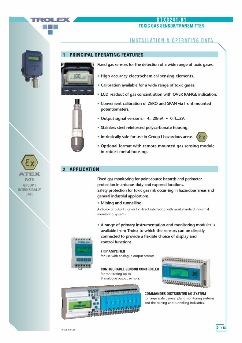
Fixed gas sensors for the detection of a wide range of toxic gases.
• High accuracy electrochemical sensing elements.
• Calibration available for a wide range of toxic gases.
• LCD readout of gas concentration with OVER RANGE indication.
• Convenient calibration of ZERO and SPAN via front mounted potentiometers.
• Output signal versions:- 4...20mA • 0.4...2V.
• Stainless steel reinforced polycarbonate housing.
• Intrinsically safe for use in Group I hazardous areas.
• Optional format with remote mounted gas sensing module in robust metal housing.
1 PRINCIPAL OPERATING FEATURES
TRIP AMPLIFIER for use with analogue output sensors.
CONFIGURABLE SENSOR CONTROLLER for monitoring up to 8 analogue output sensors.
COMMANDER DISTRIBUTED I/O SYSTEMfor large scale general plant monitoring systemsand the mining and tunnelling industries.
• A range of primary instrumentation and monitoring modules is available from Trolex to which the sensors can be directly connected to provide a flexible choice of display and control functions.
Fixed gas monitoring for point-source hazards and perimeterprotection in arduous duty and exposed locations. Safety protection for toxic gas risk occurring in hazardous areas andgeneral industrial applications.
• Mining and tunnelling. A choice of output signals for direct interfacing with most standard industrialmonitoring systems.
2 APPLICATION

SS TT XX 33 22 44 11 .. 00 11
33ISSUE B 01/08
/ 18
TOXIC GAS SENSOR/TRANSMITTER
ATEXM1
GROUP IINTRINSICALLY
SAFE
I N S T A L L A T I O N & O P E R A T I N G D A T A
3 DIMENSIONS
3.1 S T X 3 2 4 1 . 0 1 TOXIC GAS SENSOR/TRANSMITTER
3.2 S T X 3 2 4 1 . 0 1 . 8 4 TOXIC GAS SENSOR/TRANSMITTER with Remote Gas Sensing Module.
ALL DIMENSIONS IN MM
110
97
6326
7414
8
6438
Ø10Ø6.
5
Gas Entry Port
3 Cable Entries to suit M20 Glands or Multi Pole Connector
2 Holes forM6 SocketCap Head
Fixing Screws
External Earth Terminal
97
Ø45
110
97
148
2 Holes forM6 SocketCap Head
Fixing Screws
External Earth Terminal
2000 (standard)
2 Fixing Holes forM6 Socket Cap
Head Screws
124.
015
.0
26.0
110
97
6326
4514
8
6438
Ø10Ø6.
5
Gas Entry Port
3 Cable Entries to suit M20 Glands or Multi Pole Connector
2 Holes forM6 SocketCap Head
Fixing Screws
External Earth Terminal
ALL DIMENSIONS IN MM

SS TT XX 33 22 44 11 .. 00 11
44ISSUE B 01/08
/ 18
TOXIC GAS SENSOR/TRANSMITTER
ATEXM1
GROUP IINTRINSICALLY
SAFE
I N S T A L L A T I O N & O P E R A T I N G D A T A
4 TECHNICAL DETAILS
4.1 SpecificationMeasuring Ranges: CO: 0...50ppm NO: 0...100ppm H2: 0...1000ppm
CO: 0...250ppm NO2: 0...20ppm O2: 0...25%CO: 0...500ppm H2S: 0...50ppmCl2: 0...10ppm SO2: 0...20ppmOther ranges can be supplied to specification.
Ambient Temperature Limits: –10°C...40°C.Humidity: 15...90% non condensing.Storage Temperature Limits: –20°C...60°C.Ambient Pressure Limits: 1 bar ± 100 mbar absolute.Protection Classification: Dust & waterproof to IP66. Gas inlet port to IP54.Housing Material: Stainless steel reinforced polyamide 6.Sensing Principle: Electrochemical cell.Cell Operating Life: >2 years (in clean atmosphere).Electrical Connections: 4mm barrier/clamp terminals.Information Display: Graphic LCD.Vibration Limits (BS2011): 10...100Hz, 0.25mm pk. 100...600Hz, 2g pk.Impact Limits: 20 joules (housing).Nett Weight: 450g.Certification: EEx ia I M1.
CO
CO
NO2
NO
H2S
SO2
CO
H
Cl2
O2
TOXIC GASES • ELECTROCHEMICAL CELLSSENSING LINEARITY DRIFT REPEATABILITY RESPONSE OPERATINGRANGE TIME T63% LIFE*
STX3241.01.250.50 CARBON MONOXIDE 0...50ppm ±2% FS 2% month ±2% 9 secs >2 years
STX3241.01.250.250 CARBON MONOXIDE 0...250ppm ±2% FS 2% month ±2% 9 secs >2 years
STX3241.01.250.500 CARBON MONOXIDE 0...500ppm ±2% FS 2% month ±2% 9 secs >2 years
STX3241.01.254.20 NITROGEN DIOXIDE 0...20ppm ±2% 2% month ±2% 15 secs >2 years
STX3241.01.259.100 NITRIC OXIDE 0...100ppm ±5% 2% month ±2% 9 secs >2 years
STX3241.01.251.50 HYDROGEN SULPHIDE 0...50ppm ±2% 2% month ±2% 14 secs >2 years
STX3241.01.261.1000 HYDROGEN 0...1000ppm ±2% 2% month ±2% 14 secs >2 years
STX3241.01.252.20 SULPHUR DIOXIDE 0...20ppm ±2% 2% month ±2% 7 secs >2 years
STX3241.01.255.10 CHLORINE 0...10ppm ±2% 2% month ±2% 7 secs >2 years
STX3241.01.257.25 OXYGEN 0...25% ±2% 2% month ±2% 7 secs >2 years
*IN CLEAN AIR
4.2 Electrical Details
20mA
4
2V
0.4
15Hz
5
20mA
4
2V
0.4
15Hz
5
S T X 3 2 4 1 . 0 1 GROUP I APPLICATIONS (12V dc)
Output: 0.4...2V dcMin Load 10k ohmsSupply 6.5...14.4V dcMax Supply Current 10mA (@12V)
Output: 4...20mAMax Load @12V 250 ohms @ 12VSupply 6.5...14.4V dcMax Supply Current 30mA (@12V)

SS TT XX 33 22 44 11 .. 00 11
55ISSUE B 01/08
/ 18
TOXIC GAS SENSOR/TRANSMITTER
ATEXM1
GROUP IINTRINSICALLY
SAFE
I N S T A L L A T I O N & O P E R A T I N G D A T A
(Refer to Test Certificate provided with the sensor).
• Does the output signal of the sensor concur with the input requirement of the monitoring equipment being used?
• Is the correct supply voltage available for the sensor?
• Is the type of gas and its anticipated maximum level of concentration, within the operating parameters of the sensor?
• Is the temperature variation range, at the installation, within the stated temperature range of the sensor?
• Is the hazardous area classification correct?
5 INSTALLATION
A20mA
4
V2V
0.4
Hz15Hz
5
A20mA
4
V2V
0.4
Hz15Hz
5
12V dc
GROUP I
5.1 Conformity Check
S T X 3 2 4 1 . 0 1 TOXIC GAS SENSOR/ TRANSMITTER GROUP I
TYPE OF GAS
OUTPUT SIGNAL • 0.4...2V (11)• 4...20mA (12)
SSTTAANNDDAARRDD OOPPTTIIOONNSS AAVVAAIILLAABBLLEE
Refer to Section 4.1
S T X 3 2 4 1 . 0 1 . 8 4 TOXIC GAS SENSOR/ TRANSMITTER GROUP Iwith Remote Gas Sensing Module.
TYPE OF GAS
OUTPUT SIGNAL • 0.4...2V (11)• 4...20mA (12)
Refer to Section 4.1

SS TT XX 33 22 44 11 .. 00 11
66ISSUE B 01/08
/ 18
TOXIC GAS SENSOR/TRANSMITTER
ATEXM1
GROUP IINTRINSICALLY
SAFE
I N S T A L L A T I O N & O P E R A T I N G D A T A
5 INSTALLATION continued
5.2 Location
EEaacchh iinnssttaallllaattiioonn nneeeeddss ttoo bbee ccoonnssiiddeerreedd iinn iittss oowwnn rriigghhtt,, wwiitthh rreeffeerreennccee ttoo ssaaffeettyy aauutthhoorriittiieess aanndd iinn ccoommpplliiaannccee wwiitthh mmaannddaattoorryy llooccaall ssaaffeettyy rreegguullaattiioonnss..TThhee sseennssoorr mmuusstt bbee ooppeerraatteedd iinn aaccccoorrddaannccee wwiitthh tthhee IInnssttaallllaattiioonn aanndd OOppeerraattiinngg DDaattaa ttoo mmaaiinnttaaiinn ssaaffeettyy,, rreelliiaabbiilliittyy aanndd ttoo pprreesseerrvvee IInnttrriinnssiicc SSaaffeettyy iinntteeggrriittyy wwhheerree aapppplliiccaabbllee..
It is important that sensors are located in positions determined in consultation with those who have specialised knowledge of the plant or installation and of the principles of gas dispersion. Reference should also be made to those responsible for the engineering layout and topology of the plant as they will be most familiar with the nature of the potential dangers and the most likely sources of gas release.
It is also important to recognise that the characteristics of the gas source can be influenced by many factors; including the relative density or buoyancy of the gas, the pressure at the point of release, the ambient temperature and the ventilation of the site.
Sensor coverage cannot be simply expressed in terms of ‘number per unit area’. Sensors need to be sited where they are capable of monitoring those parts of a plant where gas may accumulate or when a source of gas release is expected to occur. This way the earliest possible warning of a gas release can be given to initiate shutdown functions, alarm functions or safe evacuation of the premises.
5.3 System Integrity
If a gas monitoring system should fail for any reason, it is important that the system is capable of immediately alerting operational staff to this fact. The sensor will indicate a system failure or mechanical defect and this information can be utilised to initiate a warning alarm. It is good practice to provide emergency facilities to protect against the loss of the mains power supply. Standby batteries can be incorporated with automatic changeover facilities, so guaranteeing continued operation of the pressure sensing system even in the event of a plant breakdown as a result of a power supply failure. Certainly, in critical plants, duplication or triplication of sensors is recommended.
The Trolex TX9042 or TX9044 Programmable Sensor Controller can be programmed to operate with sensors in the multiple voting mode.
5.4 Sensor Management
A very important part of an efficient gas monitoring system is the training of plant personnel in operation and maintenance of the sensors and the complete monitoring system. Training facilities can be provided by qualified Trolex application engineers.
Once a sensor installation is complete, the sensor locations and types should be formally recorded and a planned test and maintenance procedure instituted.

5.6 Hazardous Areas
Do not disassemble the sensor whilst in the hazardous area or use a sensor that has a damaged housing in the hazardous area.
5.7 Evacuation
If a dangerous level of gas concentration is detected by the instrument, leave the area immediately.
5.8 Operating Life
Electrochemical cells contain an electrolyte that is gradually consumed during use.
The average life is about two years, dependent upon the duty cycle.
The response should be checked at regular intervals.
SS TT XX 33 22 44 11 .. 00 11
77ISSUE B 01/08
/ 18
TOXIC GAS SENSOR/TRANSMITTER
ATEXM1
GROUP IINTRINSICALLY
SAFE
I N S T A L L A T I O N & O P E R A T I N G D A T A
5 INSTALLATION continued
5.5 Relative Density
The relative density or buoyancy of the gas or vapour with respect to air is a very important consideration. This determines its propensity to rise or fall when released into the atmosphere.
Gases or vapours with a buoyancy less than air will tend to rise from the source of release.
Conversely, gases or vapours heavier than air will tend to fall and accumulate in concentrations for long periods of time.
This is a particular problem in pits, trenches, machine rooms, etc. Normal air movements in and around such gas concentrations will have the inevitable effect of producing zones of of highly toxic mixtures.
This knowledge of the characteristics of the gas assists when positioning the gas sensor.
The behaviour of the gas accumulation will also be affected by the velocity and location of the gas release and by ambient air movement caused by ventilation systems or draughts.
Pockets of gas can be trapped in trenches or ceiling cavities, all of which adds to the unpredictability of critical gas concentrations.
Hydrogen LIGHTER THAN AIRCarbon Dioxide
Nitric OxideOxygen
Sulphur Dioxide HEAVIER THAN AIRChlorine
Nitrogen Dioxide

SS TT XX 33 22 44 11 .. 00 11
88ISSUE B 01/08
/ 18
TOXIC GAS SENSOR/TRANSMITTER
ATEXM1
GROUP IINTRINSICALLY
SAFE
I N S T A L L A T I O N & O P E R A T I N G D A T A
5.9 Sensitivity
Electrochemical cells for toxic gases can be affected by other interfering gases which may displace the subject gas being monitored. Steam laden atmospheres and condensation can also reduce the sensitivity.
5.10 Flammable
Be aware that some toxic gases are also ‘flammable’ at high percentage concentrations.
5.11 Biased Sensors
Some gas sensors must be continuously powered to maintain the calibration.
If the gas head is removed from any supply voltage for greater than 10 minutes, itcould take 24–48 hours to restore its calibration.
5 INSTALLATION continued

6.1 0.4...2V Output Signal
A low impedance two-wire voltage output signal requiring a separate power supply to the sensor. This can be derived from a Trip Amplifier or Programmable Sensor Controller, when one of those is used as the monitoring instrument.
This connection configuration works well up to about 10 metresdistance between the sensor and the monitoring equipment.
Both the signal and the power supply to the sensor are being carried in the common 0V conductor so at some point – influenced by the length of the cable and the resistance of the cable cores – the current flowing in the 0V conductor will impose an unacceptable voltage error onto the signal.
This effect can be reduced on long distance connections by increasing the size of the cable cores, or even better, running a separate 0V conductor to power the sensor enabling operating distances up to 1000m.
SS TT XX 33 22 44 11 .. 00 11
99ISSUE B 01/08
/ 18
TOXIC GAS SENSOR/TRANSMITTER
ATEXM1
GROUP IINTRINSICALLY
SAFE
I N S T A L L A T I O N & O P E R A T I N G D A T A
6 CONNECTIONS
S T X 3 2 4 1 . 0 1 TOXIC GAS SENSOR/ TRANSMITTER GROUP I
A20mA
4
V2V
0.4
Hz15Hz
5
OUTPUT SIGNAL OPTIONS
AAPPPPLLIICCAATTIIOONN •• GGRROOUUPP II HHAAZZAARRDDOOUUSS AARREEAASS
1 2 3 4 5 6 7 8
Signal0V
+V
1 2 3 4 5 6 7 8
Signal0V
+V
1 2 3 4 5 6 7 8
1 2 3 4 5
Signal
0V
0V +VSignal
0V Supply
Supply
6 7 8
0V+V
+V
1 2 3 4 5 6 7 8
Signal
0V
+V
STX3261
1 2 3 4 5
STX3261
+V Supply
0V
0.4...2V signal
6 7 8
TX9132
3 WIRE
1 2 3 4 5
STX3261
+V Supply
0V
0.4...2V signal
6 7 8
0V Supply
TX9132
4 WIRE
STX3241
STX3241

1 2 3 4 5
STX3261
+V Supply
0V
4...20mA signal
6 7 8
0V Supply
MonitoringDevice
1 2 3 4 5
STX3261
+V Supply
0V
4...20mA signal
6 7 8
TX9131
SS TT XX 33 22 44 11 .. 00 11
1100ISSUE B 01/08
/ 18
TOXIC GAS SENSOR/TRANSMITTER
ATEXM1
GROUP IINTRINSICALLY
SAFE
I N S T A L L A T I O N & O P E R A T I N G D A T A
6 CONNECTIONS continued
6.2 4...20mA Output Signal
The sensor may be connected in the 3 or 4 wire connection mode.
The power supply for the sensor may be sourced from the monitoring equipment (eg. TX9131 Trip Amplifier or a TX9042 Programmable Sensor Controller)or from a separate power supply.
3 WIRE
4 WIRE
A20mA
4
V2V
0.4
Hz15Hz
5
1 2 3 4 5 6 7 8
Signal0V
+V
1 2 3 4 5 6 7 8
Signal0V
+V
AAPPPPLLIICCAATTIIOONN •• GGRROOUUPP II HHAAZZAARRDDOOUUSS AARREEAASS
6.3 Using Gas Sensors in Hazardous Areas
GROUP I HAZARDOUS AREAS (MINING)
S T X 3 2 4 1 . 0 1 TOXIC GAS SENSOR/ TRANSMITTER
• All options of the STX3241.01 sensor (0.4...2V, 4...20mA) are certified Intrinsically Safe for use in Group I hazardous areas (Mining) when used with approved equipment –eg. TX9131 Trip Amplifier or a TX9042 Programmable SensorController.
• THE COMPLETE SYSTEM, BOTH SENSOR AND MONITORING DEVICE, CAN BE MOUNTED IN THE HAZARDOUS AREA.
• The interconnecting cable between the sensor and the monitoring device must have steel wire armoured protection ora braided earth screen. The cross sectional area of the conductors must be a minimum of 1mm2.
TX9131
HAZARDOUS
SAFE
TX6363.01STX3241.01
STX3241
STX3241

SS TT XX 33 22 44 11 .. 00 11
1111ISSUE B 01/08
/ 18
TOXIC GAS SENSOR/TRANSMITTER
ATEXM1
GROUP IINTRINSICALLY
SAFE
I N S T A L L A T I O N & O P E R A T I N G D A T A
7 CONTROLS AND INDICATORS
S T X 3 2 4 1 . 0 1 TOXIC GAS SENSOR/ TRANSMITTER
Gas Entry Port
Cable Entries
External Earth Terminal 97
Gas Entry Port
Earth Terminal
Gas ConcentrationDisplay
Span Potentiometer (behind front cover)Offset Potentiometer

SS TT XX 33 22 44 11 .. 00 11
1122ISSUE B 01/08
/ 18
TOXIC GAS SENSOR/TRANSMITTER
ATEXM1
GROUP IINTRINSICALLY
SAFE
I N S T A L L A T I O N & O P E R A T I N G D A T A
The gas sensing module will gradually change its responsecharacteristics, by a small amount, during normal use. The output signal is standardised so the module can be quicklychanged when necessary.
The gas sensing module may be re-calibrated when required, using a Trolex TX6520 Gas Test Kit equipped with both Air and Test Gas canisters.
8.1 Prepare to Calibrate
• The sensor should be powered for a minimum of 30 minutes prior to commencing calibration.
• Connect the application tube of the gas test kit to the inlet aperture of the gas sensing module.
8.2 Calibrate Zero
• Apply purge air, at a flow rate of 0.3...1.0 l/min.
• Allow reading to stabilise.
• If necessary, adjust Offset potentiometer until display reads 0.00.
• Remove purge air.
8.3 Calibrate Span
• Apply calibration gas, minimum of 25% of full scale.
• Allow reading to stabilise.
• Adjust Span potentiometer until display reads the same value asthe calibration gas being used.
• Remove span gas.
8 CALIBRATION
AIR
TEST GAS
AIR
TEST GAS
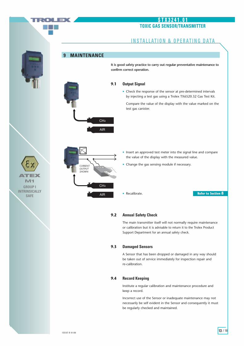
It is good safety practice to carry out regular preventative maintenance toconfirm correct operation.
9.1 Output Signal
• Check the response of the sensor at pre-determined intervals by injecting a test gas using a Trolex TX6520.32 Gas Test Kit.
Compare the value of the display with the value marked on thetest gas canister.
• Insert an approved test meter into the signal line and compare the value of the display with the measured value.
• Change the gas sensing module if necessary.
• Recalibrate.
9.2 Annual Safety Check
The main transmitter itself will not normally require maintenance or calibration but it is advisable to return it to the Trolex Product Support Department for an annual safety check.
9.3 Damaged Sensors
A Sensor that has been dropped or damaged in any way should be taken out of service immediately for inspection repair and re-calibration.
9.4 Record Keeping
Institute a regular calibration and maintenance procedure and keep a record.
Incorrect use of the Sensor or inadequate maintenance may not necessarily be self evident in the Sensor and consequently it must be regularly checked and maintained.
SS TT XX 33 22 44 11 .. 00 11
1133ISSUE B 01/08
/ 18
TOXIC GAS SENSOR/TRANSMITTER
ATEXM1
GROUP IINTRINSICALLY
SAFE
I N S T A L L A T I O N & O P E R A T I N G D A T A
9 MAINTENANCE
AIR
CH4
AIR
CH4
TX6389�Interface�Unit
HAZ SAFE
AIR
CH4
AIR
CH4
TX6389�Interface�Unit
HAZ SAFE
CURRENTOUTPUTSHOWN
Refer to Section 8

SS TT XX 33 22 44 11 .. 00 11
1144ISSUE B 01/08
/ 18
TOXIC GAS SENSOR/TRANSMITTER
ATEXM1
GROUP IINTRINSICALLY
SAFE
I N S T A L L A T I O N & O P E R A T I N G D A T A
9.5 Maintenance and Calibration Log
ORDER REF STX3241.01 DATE SUPPLIED
SERIAL No. USER
GAS TYPE LOCATION
8 MAINTENANCE continued
DATE SCHEDULED FAILURE RE-CALIBRATE CHANGE GAS RETURN TO COMMENTSSENSING MANUFACTURERMODULE

SS TT XX 33 22 44 11 .. 00 11
1155ISSUE B 01/08
/ 18
TOXIC GAS SENSOR/TRANSMITTER
I N S T A L L A T I O N & O P E R A T I N G D A T A
ATEXM1
GROUP IINTRINSICALLY
SAFE
10 APPROVALS AND CERTIFICATION
10.1 Intrinsically SafeThe instrument is certified Intrinsically Safe Group I apparatus for use in potentially explosive atmospheres to EURONORM standards when used with an approved power supply or safety barriers.
The sensor is designed to comply with the ATEX directive (94/9/EEC).
S T X 3 2 4 1 . 0 1 TOXIC GAS SENSOR/ TRANSMITTER
GROUP I: I M1
EEx ia I: Sira 07ATEX2170X(Ta = –20°C...+55°C)
10.2 Electro Magnetic Compatibility.The instrument is designed to comply with the EC directive on EMC (89/336/EEC).
10.3 Compliance with ATEX Directives
Information specific to hazardous areainstallations (Reference European ATEX Directive94/9/EC, Annex II, 1.0.6.)The following applies to equipment covered bycertificate number : SIRA 07 ATEX2170.1. To comply with the requirements for intrinsic
safety, the equipment must be supplied only from associated apparatus with an appropriate safety description matching the input parameters detailed in the certificate.
2. The equipment is only certified for use in ambient temperatures in the range –20°C to +55°C and should not be used outside this range.
3. Subject to the applicable code of practice, the enclosure may be temporarily opened and the equipment worked on ‘live’ as all sparks which areinadvertently produced non-incendive for all flammable gases and dusts.
4. Installation shall be carried out in accordance withthe applicable code of practice by suitably-trained personnel.
5. Adjustments to this equipment affect operation only and have no effect on intrinsic safety.
6. Repair of this equipment shall be carried out in accordance with the applicable code of practice.
7. The certification of this equipment relies on the following materials used in its construction, to prevent the ingress of dust in mining applications:• Enclosure: Polycarbonate• Window: Polycarbonate
GB

SS TT XX 33 22 44 11 .. 00 11
1166ISSUE B 01/08
/ 18
TOXIC GAS SENSOR/TRANSMITTER
ATEXM1
GROUP IINTRINSICALLY
SAFE
I N S T A L L A T I O N & O P E R A T I N G D A T A
10 APPROVALS AND CERTIFICATION continued
INSTRUCCIONES PARA EL SENSOR/TRANSMISORSTX3241 (EHRS 1.0.6)La siguiente información deberá aparecer sin cambioalguno en las instrucciones que acompañan cadaproducto. Estas instrucciones podrán estar en unasección diferenciada dentro del Manual deoperaciones o un documento similar.Instrucciones especificas para instalaciones deáreas peligrosas (con referencia a la DirectivaEuropea ATEX 94/9/EC, Anexo II, 1.0.6.)Las siguientes instrucciones se aplican a equiposcubiertos por el certifcado número SIRA 07ATEX2170:1. Para cumplir con los requisitos de seguridad intrínseca, el equipo deberá ser suministrado solo aparatos asociados con una apropiada descripción de seguridad que iguale los parámetros de entrada detallados en el certificado.2. El equipo está certificado solo para usar en temperaturas ambientales dentro de un margen de –20°C a +55°C y no deberá ser usado fuera de este margen.3. Sujeto al código de practica indicado, el recinto podrá ser temporalmente abierto y podrá funcionar en “vivo” ya que todas las chispas que son producidas inadvertidamente no son incendiarias para ninguna clase de gases y polvos inflamables.4. La instalación deberá ser realizada de acuerdo con el código de practica por personal adecuadamente entrenado.5. Ajustes realizados a este equipo afectarán solamente el funcionamiento y no tendrán efecto alguno en la seguridad intrínseca.6. Las reparciones en este equipo deberán ser realizadas de acuerdo con el código de practica.7. La certificación de este equipo se basa en los siguientes materiales usados en su construcción para prevenir el ingreso de polvos en sus aplicaciones en minería:
• Recinto: Policarbonato• Ventana: Policarbonato
E
INSTALLATIONSBEDINGUNGEN (EHSR 1.0.6) FÜRSTX3241 SENSOR/SENDEGERÄTDie nachfolgende Information muß in unveränderterForm in den Produktbegleitunterlagen erscheinen.Diese Installationsbedingungen können in einemseperaten Teil eines Betriebshandbuches oder einesähnlichen Dokumentes plaziert werden.Bedingungen für die Installationen inexplosionsgefährdeten Räumen (EuropäischeATEX-Richtlinie 94/9/EC, Zusatz II, 1.0.6)Die folgenden Bedingungen gelten für Geräte, dieZertifikationsnummer SIRA 07 ATEX2170 tragen:1. Zwecks Erfüllung der Anforderungen bezüglich
der Eigensicherheit, darf das Gerät nur an Versorgungen angeschlossen werden, deren sicherheitstechnische. Auslegung mit den in Zertifikat aufgefürten einganggrössen übereinstimmt.
2. Das Gerät ist nur für den Einsatz bei Umgebungstemperaturen von –20°C bis +55°C zertifiziert und darf außerhalb dieses Bereiches nicht eingesetzt werden.
3. Abhängig von den jeweils geltenden Betriebsvorchriften darf das Gehäuse vorübergehend geöffnet werden, um am Gerät im“eingeschalteten” Zustand zu arbeiten, da eventuell erzeugte Funken als nicht entflammbar im Hinblick auf alle brennbare Gase und Staube gelten.
4. Die Installation muß nach den jeweils geltenden Betriebsvorschriften von qualifizierten Personen vorgenommen werden.
5. Eventuelle Einstellungen an diesem Gerät sind lediglich von betrieblicher Konsequenz und habenkeinerlei Auswirkungen auf die Eigensicherheit.
6. Reparaturen an diesem Gerät sind in Übereinstimmung mit den hierfür geltenden Vorschriften vorzunehmen.
7. Für die Zertifikation gilt, daß bei der Herstellung des Gerätes folgende Werkstoffe eingesetze werden, durch die bei Einsätzen im Bergbau Eindringen von Staub verhindert wird:• Gehäuse: Polycarbonat (PC)• Sichtglas: Polycarbonat (PC)
D

SS TT XX 33 22 44 11 .. 00 11
1177ISSUE B 01/08
/ 18
TOXIC GAS SENSOR/TRANSMITTER
ATEXM1
GROUP IINTRINSICALLY
SAFE
I N S T A L L A T I O N & O P E R A T I N G D A T A
10 APPROVALS AND CERTIFICATION continued
INSTRUCTIES (EHSR 1.0.6) VOORSENSOR/ZENDER STX3241De volgende informatie dient onveranderd in deinstructies te verschijnen die bij elk product geleverdworden. Deze instructies kunnen in een hoofdstuk ineen gebruikshandleiding of dergelijk documentopegenomen worden.Instructies met specifieke betrekking opinstallaties voor gevaarlijke ruimten (naarEuropese ATEX Richtlijn 94/9/EC, Bijlage II, 1.0.6)
De volgende punten zijn van toepassing op onderCertificaat nummer SIRA 07 ATEX2170 vallendeapparatuur:
1. Om aan de vereisten voor intrinsieke veligheid te voldoen, mag de apparatuur uitsluitend gevoed worden via een verwant apparaat met een geschikte beschrijving voor veiligheid die overeenkomt met de invoerparameters zoals op het certificaat uiteengezet staan.
2. De aparatuur is alleen officieel geschikt verklaard voor gebruik bij een omgevingstemperatuur tussen –20°C en +55°C en mag neit gebruikt worden buiten deze minimale en maximale temperaturen.
3. Mits dit tegen de van toepassing zijnde praktijkode ingaat, kan de buitenkant tijdelijk geopend worden en kan er op de apparatuur gewerkt worden terwijl deze onder stroom staat, aagezien vonken die zich per ongeluk voordoen, bij alle vlambare gassen en poeders geen brand kunnen veroorzaken.
4. Installatiewerkzaamheden dienen uitgevoerd te worden door geschikt opgeleid personeel in overeenstemming met de van toepassing zijnde praktijkcode.
5. Aanpassingen van de apparatuur mogen alleen van invloed zijn op de werking en niet op de intrinsieke veiligheid.
6. Reparatiewerkzaamheden dienen uitgevoerd te worden in overeenstemming met de van toepassing zijnde praktijkcode.
7. Het toekennen van het certificaat is afhankelijk vande volgende stoffen die in de constructie verwerktzijn, om het indringen van stof te vookomen bij torpassingen in de mijnbouw:• Buitenkant: Polycarbonaat• Venster: Polycarbonaat
NL
Spesifikk informasjon om risiko på installasjoner ieksplosjonsfarlige soner (ref. Europeisk ATEX Direktiv94/9/EC, Anneks II, 1.0.6.)
Følgende brukes til utstyr dekket av sertifikatnummerSira 02ATEX2170 (GP I).
1. For å imøtekomme/etterkomme krav for engensikkerhet, må utstyret være forsynt/tilført kun fra tilknyttede apparater med passende sikkerhetsbeskrivelse med like inngangsparametre beskrevet i sertifikatet.
2. Utstyret er kun sertifisert for bruk i omgivelsestemperaturer i området –20°C til +55°C(Gruppe I) og må ikke brukes utenfor dette området.
3. Installasjon, vedlikehold og reparasjon må bli utført i samsvar med gjeldende regler av trent personale.
4. Regulering/justering av utstyret virker kun på driften, og har ingen virkning på egensikkerheten.
5. Utstyret har ikke blitt vurdert som en sikkerhetsrelatert innretning (Dir. 94/9/EC, Anneks II, 1.5.1 to 1.5.8)
6. Utstyret er sertifisert som kategori M1 i Gruppe I anvendelser.
7. Utstyret beror på at følgende materiale er brukt i ens konstruksjon:• Hus: Polycarbonate• Vindu: Polycarbonate• Sensor-hode: Rustfritt stål
Hvis det er sannsynlig at utstyret kan komme i kontakt med aggressive stoffer, et det brukerens ansvar å forebygge dette. Således sikker på at type beskyttelse ikke utsettes for fare.
Aggressive F.eks. flytende syre eller gasser somstoffer: kan angripe metall, eller løsemiddel
som kan ha virkning på polymeric materiale.
Passende F.eks. jevnlig sjekk som en del avforsiktighet: rutineinspeksjoner eller innsette i
databladet at det er motstansdyktigtil spesifikke kjemikaler.
N

SS TT XX 33 22 44 11 .. 00 11
1188ISSUE B 01/08
/ 18
TOXIC GAS SENSOR/TRANSMITTER
I N S T A L L A T I O N & O P E R A T I N G D A T A
Many of our products are often used tomonitor the quality of environmentalconditions consequently Trolex is alsoparticularly aware of the need to protecthuman health and the environment in whichwe live.
The Company has instituted a radicalenvironment protection policy to ensure thatall aspects of our manufacturing programmehave the minimum possible detrimentalimpact on the environment. This covers allstages beginning with sustainable productdesign supported by careful selection of thematerials used in their production, through tomanaged recovery and disposal at the end ofthe useful life of a product.
This policy also incorporates the principles ofthe Waste Electrical and Electronics Equipment(WEEE) directive, and the associated Restrictionof Hazardous Substances (RoHS) directive, tobe implemented in EU countries.
Progress is already well advanced on theintroduction of a completely new range ofproducts that maximise the central principle ofsustainable design with the intention ofreducing the end-of-life cost to the end user.
All Trolex products are manufactured toexacting standards in accordance with ourstringent quality control ethos. Having chosento use one of our products will, in itself,guarantee extended durability and a longoperating life, endorsed by our commitmentto recycling and recovery.
All packaging materials are carefully selected to be bio-degradable or re-cycleable where possible.
All plastic materials are identified for recycling purposes and re-cycled materials are used where it is possible to do so.
PROTECTING THE ENVIRONMENT
Printing paper and material are sourced from suppliers that have a declared environmental management system.
Product design centred around high quality and long term durability. Modular architecture both in construction and software design suitablefor future upgrades and adaptability to alternative duty.
Ease of product disassembly, minimisation of fixing devices, and clear separation of functional parts to benefit re-use and re-cycling.
Control and monitoring of suppliers of components and sub-assemblies. Deal only with uppliers that have a defined commitment to environmental monitoring principles.
Control the use of restricted substances within the design process. Deal only with suppliers that have a defined commitment to the control of restricted substances.
Provide an efficient high speed service within Trolex for repair, refurbishing and conversion of products for alternative duty.
Provision of an end-of-life product Take-back service for recovery, re-use, and recycling of electrical and electronic components. Retain the packaging of a new product and re-use it to return the device to us at the end of its working life. Trolex will guarantee to recover all materials and components, where practicable and arrange for them to be re-cycled in an appropriate and in a safe manner.
T R O L E X L I M I T E DNEWBY ROAD, HAZEL GROVE, STOCKPORT,
CHESHIRE SK7 5DY, UK
T: +44 (0)161 483 1435E: [email protected]
W: trolex.com
ATEXM1
GROUP IINTRINSICALLY
SAFE