two piece mounts - lord...
TRANSCRIPT

TWO PIECE MOUNTSVIBRATION, SHOCK & MOTION CONTROL
Headquarters1515 16th StreetRacine, WI 53403
Phone 262.632.2345Toll Free 800.657.0747
Fax 262.632.0271DELTAFLEX.com™
LORD INDUSTRIAL SHOCK AND VIBRATION MOUNTS DISTRIBUTOR
™
RUBBER PARTS CATALOG®.com

Plateform Mounts Center-Bonded Mounts Unique Mounts Two-Piece Mounts Bushings Sandwich Mounts Machinery Mounts Couplings
Gro
mm
et Is
olat
ors
Pla
tefo
rm
Hea
vy-D
uty
Mul
tipla
ne
CB
-110
0 S
erie
s
CB
-118
0 S
erie
s
CB
A S
erie
s
CB
A-5
0 S
erie
s
STA
Ser
ies
Saf
etie
d Tu
befo
rm
Con
ical
Sur
face
-Eff
ect
Bin
ocul
ar/S
plit
CB
B/C
BC
Ser
ies
SS
B S
erie
s
CB
-220
0 S
erie
s
Cen
ter-
Bon
ded
Squ
are-
Bon
ded
Sm
all
Med
ium
Larg
e
Latt
ice
Cha
n-L
Indu
stri
al S
hock
Leve
ling
She
ar-T
ype
Spo
ol-T
ype
Bus
hing
-Typ
e
LCR
Ser
ies
LCD
Ser
ies
Actuators X
Cabs X X X X X X X X X X X X X X X
Computer & Accessories X X X X X X
Conveyors X X X X X X
Delicate Equipment X X X X X X
Drive Lines X X X X X X
Electric Motors X X X X X X X X X X X X X X X X X X X X X X
Electronics X X X X X X X
Engines X X X X X X X X X X X X X X X X X X X X
Engine Generator/Pump Sets X X X X X X X X X X X X X X X X X X X X X X
Fans/Blowers X X X X X X X X X X X X X X X X X X X X X X X X
Heating/Cooling Units X X X X X X X X X X X X X X X X X X X X X
Instruments & Gauges X X X X X
Machinery - Punch, Milling, Presses X X X X X X X X X X X X X X X X X X X X X X X
Oil & Gas Pipelines X
Pumps / Compressors X X X X X X X X X X X X X X X X X X X X X X X X X
Shakers / Vibrators X X X X X X X X X X X X X X X
Shipping Containers X X X
Vehicle Accessories X X X X X X X X X X X X X X X X X X X X X X
Wind Power Applications X X X X X X X X X X X X X
High Temperature Applications 149º C (to 300º F) Contact LORD to request information.
APPLICATION SELECTOR GUIDE
We offer standardized products to meet most applications. Some control problems, however, require specialized solutions such as a custom-designed mount or a combination of LORD products. Our experts in vibration and noise control can analyze your individual requirements and provide you the most effective and affordable solution ... Ask Us How.
OUR SOLUTIONS
LORD Two-Piece Mounts are designed for applications involving severe dynamic forces in the static load direction, as well as the rebound direction. Travel is limited in both directions by rubber in compression that provides snubbing.
LORD Binocular/Split Mounts are designed for applications involving severe dynamic forces in the static load direction, as well as the rebound direction. Travel is limited in both directions by rubber in compression that provides snubbing.
TWO-PIECE MOUNTS BINOCULAR/SPLIT MOUNTS
Compression Load Range: 178 - 15,352 N (40 - 3,450 lbs) Compression Load Range: 4,450 - 6,675 N (1,000 - 1,500 lbs)
LORD Plateform Mounts provide effective isolation against vibration. The contour of the fl exing element was developed to provide uniform stress distribution. This, plus high strength bonding and the use of specially compounded elastomers, provides maximum service life.
LORD Grommet Isolators provide effective, economical vibration isolation for light loads. They are suitable for commercial and military applications including computers, disk drives, business machines, precision instrumentation and general industrial equipment.
PLATEFORM MOUNTS GROMMET ISOLATORS
Compression Load Range: 2 N - 2,225 N (0.5 - 500 lbs) Compression Load Range: 4 - 27 N (1 - 6 lbs)
LORD Machinery Mounts are designed to support heavy equipment and isolate intermittent or continuous vibration. The result is greater machine accuracy, longer service life, smoother operation and reduced maintenance. These mounts are available in four types to suit different needs.
LORD Center-Bonded Bushings and Square-Bonded Bushings are used in applications where the absorption shock, attenuation of noise, reduction of wear and elimination of lubrication is required.
MACHINERY MOUNTS BUSHINGS
Compression Load Range: 223 - 33,375 N (50 - 7,500 lbs)
Compression Load Range: 890 - 41,385 N (200 - 9,300 lbs)
LORD Center-Bonded Mounts isolate vibration, control shock and reduce noise due to structure borne vibrations. Available in a full range of rated load capacities and able to withstand shock loads of 10 g’s, these mounts effectively protect equipment and improve operator comfort. They are ideal for automotive, marine, railroad and industrial markets.
Effi cient power transmission and driveline component durability are among powertrains designers’ most important concerns. Increased durability and up-time are two characteristics demanded by purchasers of today’s complex and expensive machinery. These demands can only be met with reliable, trouble-free, smooth-running powertrains free from damaging loads that compromise component life.
CENTER-BONDED MOUNTSFLEX-BOLT® SANDWICH MOUNTS
Compression Load Range: 27 - 59,808 N (6 - 13,440 lbs) Compression Load Range: 334 - 9,345 N (75 - 2,100 lbs)Shear Load Range: 4.45 - 7,476 N (1 - 1,680 lbs)
Surface-Effect Mounts combine surface-effect damping principles with traditional rubber-bonded-to-metal technology. The result is a soft mount capable of providing effective damping over large defl ections and a wide range of frequencies. As cab and engine mounts in on- and off-highway vehicles, Surface-Effect Mounts meet the most demanding requirements for vibration isolation and noise attenuation while controlling motion.
Compression Load Range: 3,115 - 6,987 N (700 - 1,570 lbs) Compression Load Range: 801 - 11,392 N (180 - 2,560 lbs)
LORD Conical Mounts provide effective vibration isolation and noise attenuation with a simple, robust mount design. Consistent performance, high load bearing capabilities and a choice of radial stiffness characteristics are key features of these mounts. For more demanding vibration and noise reduction requirements, LORD integrates Conical Mounts with surface-effect technology to form an advanced control solution known as Surface-Effect Systems.
SURFACE-EFFECT MOUNTS CONICAL MOUNTSSURFACE EFFECT MOUNTS CONICAL MOUNTS
SANDWICH MOUNTS - FLEX-BOLTTM CENTER-BONDED MOUNTS
TWO-PIECE MOUNTS BINOCULAR/SPLIT MOUNTS
PLATEFORM MOUNTS GROMMET ISOLATORS
MACHINERY MOUNTS BUSHINGS
SOLUTIONS - FOR A WORLD IN MOTION
DELTAFLEX.com Phone 262.632.2345 Fax 262.632.0271 [email protected], RubberPartsCatalog, df Logo and its combinations are Registered Trade Marks of Delta Flexible Products, Inc.
Copyright © 2012 Delta Flexible Products, Inc. All Right ReservedLORD and “Ask Us How” are Registered Trade Marks of LORD Corporation or one of its subsidiaries.

DELTAFLEX®
Offering thousands of standard industrial rubber products and innovative “low” and “high” tech custom elastomeric products.
DELTAFLEX®
PAGE3DELTAFLEX.com Phone 262.632.2345 Fax 262.632.0271 [email protected]
LO
RD
®
TWO PIECE MOUNTSTW
O P
IECE M
OU
NTS
A part’s listing in this catalog does not guarantee its availability.DeltaFlex, RubberPartsCatalog, df Logo and its combinations are Registered Trade Marks of Delta Flexible Products, Inc.
Copyright © 2012 Delta Flexible Products, Inc. All Right ReservedLORD and “Ask Us How” are Registered Trade Marks of LORD Corporation or one of its subsidiaries.
VIBRATION, SHOCK & MOTION CONTROL
A part’s listing in this catalog does not guarantee its availability.To download/print the most current catalog, go to www.lordfulfi llment.com/upload/PC7000.pdf. Rev.1 10/08
Page 69 of 124TWO-PIECE MOUNTS
Two-Piece MountsFeaturing: CBB and CBC Series SSB Series CB-2200 Series
LORD Two-Piece Mounts are designed for applications involving severe dynamic forces in the static load direc-tion, as well as the rebound direction. Travel is limited in both directions by rubber in compression which provides snubbing.
These mounts are designed to support engines, cabs and accessory units, and accommodate frame racking and twisting while isolating vibration and absorbing shock.
Typical applications for Two-Piece Mounts include on-highway, off-highway vehicles, construction and industrial machines.
Features and Benefi ts• Dynamically effective in all directions
• Prevent mechanical transmission of noise
• Accommodate misalignment and distortion
• High rebound capacity
• Easy to install with common tools
• Standard bolt torque assures proper assembly
• Top and bottom parts alike, cannot be misassembled
• Fail-safe assembly
• Sized for English and Metric bolts
• Long dependable service life
• Economical
Need pricing or current inventory?
CALL US @ 800.657.0747Ask for Quoting
Features and Benefits
“...designed for applications involving severe dynamic forces in both the static load direction and the rebound direction....”
ENGINEERING ASSISTANCEFrequently vibration isolation problems require a system engineering analysis. DeltaFlex has the computer capabil-ity, as well as specialized programs, for analyzing engine/transmission combinations. The output from these analyses is a mounting proposal which optimizes performance over the complete range of operating speeds. This service is available to you upon request. If you require this type of engineering assistance please call 800.657.0747 we will be glad to assist you.
A part’s listing in this catalog does not guarantee its availability.To download/print the most current catalog, go to www.lordfulfi llment.com/upload/PC7000.pdf. Rev.1 10/08
Page 69 of 124TWO-PIECE MOUNTS
Two-Piece MountsFeaturing: CBB and CBC Series SSB Series CB-2200 Series
LORD Two-Piece Mounts are designed for applications involving severe dynamic forces in the static load direc-tion, as well as the rebound direction. Travel is limited in both directions by rubber in compression which provides snubbing.
These mounts are designed to support engines, cabs and accessory units, and accommodate frame racking and twisting while isolating vibration and absorbing shock.
Typical applications for Two-Piece Mounts include on-highway, off-highway vehicles, construction and industrial machines.
Features and Benefi ts• Dynamically effective in all directions
• Prevent mechanical transmission of noise
• Accommodate misalignment and distortion
• High rebound capacity
• Easy to install with common tools
• Standard bolt torque assures proper assembly
• Top and bottom parts alike, cannot be misassembled
• Fail-safe assembly
• Sized for English and Metric bolts
• Long dependable service life
• Economical

DELTAFLEX®
Offering thousands of standard industrial rubber products and innovative “low” and “high” tech custom elastomeric products.
DELTAFLEX®
PAGE4L
OR
D®
DELTAFLEX.com Phone 262.632.2345 Fax 262.632.0271 [email protected]
TWO PIECE MOUNTSTW
O P
IECE
MO
UN
TS
A part’s listing in this catalog does not guarantee its availability. DeltaFlex, RubberPartsCatalog, df Logo and its combinations are Registered Trade Marks of Delta Flexible Products, Inc.
Copyright © 2012 Delta Flexible Products, Inc. All Right ReservedLORD and “Ask Us How” are Registered Trade Marks of LORD Corporation or one of its subsidiaries.
A part’s listing in this catalog does not guarantee its availability.To download/print the most current catalog, go to www.lordfulfi llment.com/upload/PC7000.pdf. Rev.1 10/08
Page 70 of 124TWO-PIECE MOUNTS
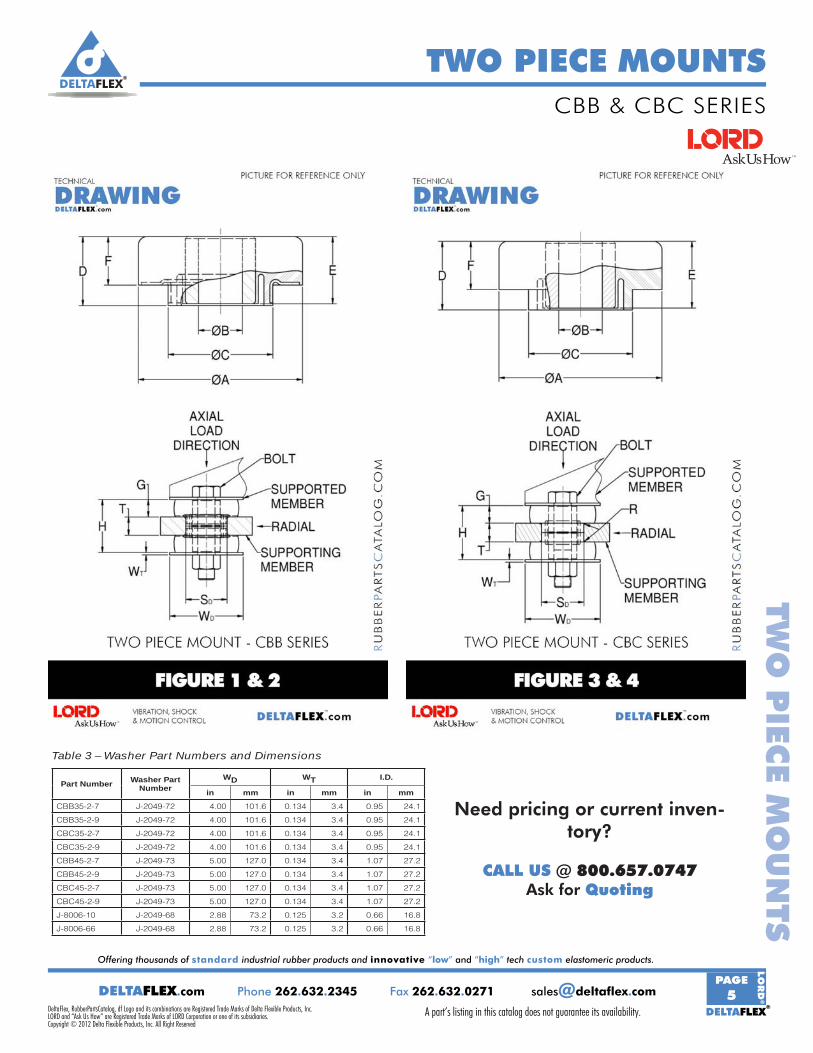
CBB and CBC Series
Table 1 – Specifi cations and Dimensions
Part Number See Figure
Maximum Axial Static Load Rating at
Defl ection Part Dimensions
lb at in N at mmA B C D Ref. E F
in mm in mm in mm in mm in mm in mm
CBB35-2-7 1 & 2 440 at 0.05 1960 at 1.27 3.50 88.9 0.938 23.8 2.24 56.9 1.48 37.6 1.44 36.6 1.04 26.4
CBB35-2-9 1 & 2 940 at 0.05 4180 at 1.27 3.50 88.9 0.938 23.8 2.25 57.2 1.48 37.6 1.44 36.6 1.04 26.4
CBC35-2-7 3 & 4 500 at 0.05 2225 at 1.27 3.50 88.9 0.938 23.8 2.23 56.6 1.60 40.6 1.44 36.6 1.04 26.4
CBC35-2-9 3 & 4 875 at 0.05 3890 at 1.27 3.50 88.9 0.938 23.3 2.23 56.6 1.60 40.6 1.44 36.6 1.04 26.4
CBB45-2-7 1 & 2 1000 at 0.06 4448 at 1.59 4.50 114.3 1.06 27.1 2.48 63.0 1.76 44.7 1.69 42.9 1.32 33.5
CBB45-2-9 1 & 2 1565 at 0.06 6960 at 1.59 4.50 114.3 1.06 27.1 2.48 63.0 1.76 44.7 1.69 42.9 1.32 33.5
CBC45-2-7 3 & 4 1030 at 0.06 4585 at 1.59 4.50 114.3 1.06 27.1 2.48 63.0 1.94 49.3 1.69 42.9 1.32 33.5
CBC45-2-9 3 & 4 1565 at 0.06 6950 at 1.59 4.50 114.3 1.06 27.1 2.48 63.0 1.94 49.3 1.69 42.9 1.32 33.5
J-8006-10 3 & 4 440 at 0.04 1960 at 0.95 2.50 63.5 0.64 16.3 1.63 41.3 0.81 20.6 0.56 14.2 0.62 15.7
J-8006-66 3 & 4 565 at 0.04 2515 at 0.95 2.50 63.5 0.64 16.3 1.50 38.1 1.19 30.2 0.94 23.9 0.62 15.7
All metal parts are made of low carbon steel.
Mounts and washers only supplied by LORD. These loads are for on-highway and general industrial applications. For off-highway, use 90% of the load shown.
Installed dimensions are under no load.
* For tightening torque information, refer to Tightening Torque Charts section.
Table 2 – Specifi cations and Dimensions
Part Number
Part Dimensions Recommended Bolt Information*
G H SD ±0.015 R T Size Grade or Class
in mm in mm in mm in mm in mm English Metric SAE J429 SAE J1199
CBB35-2-7 0.94 23.9 2.88 73.2 2.26 57.5 — — 1.00 25.4 7/8 M20 8 10.9
CBB35-2-9 0.94 23.9 2.88 73.2 2.26 57.5 — — 1.00 25.4 7/8 M20 8 10.9
CBC35-2-7 0.94 23.9 2.88 73.2 2.26 57.5 0.12 3.1 1.00 25.4 7/8 M20 8 10.9
CBC35-2-9 0.94 23.9 2.88 73.2 2.26 57.5 0.12 3.1 1.00 25.4 7/8 M20 8 10.9
CBB45-2-7 1.19 30.2 3.38 85.8 2.53 64.3 — — 1.00 25.4 1 M24 8 10.9
CBB45-2-9 1.19 30.2 3.38 85.8 2.53 64.3 — — 1.00 25.4 1 M24 8 10.9
CBC45-2-7 1.19 30.2 3.38 85.8 2.53 64.3 0.12 3.1 1.00 25.4 1 M24 8 10.9
CBC45-2-9 1.19 30.2 3.38 85.8 2.53 64.3 0.12 3.1 1.00 25.4 1 M24 8 10.9
J-8006-10 0.47 11.9 1.12 28.5 1.65 41.9 0.03 0.76 0.18 4.6 5/8 M16 2 9.8
J-8006-66 0.50 12.7 1.88 47.8 1.53 38.9 0.06 1.5 0.88 22.4 5/8 M16 8 10.9
CBB & CBC SERIES
A part’s listing in this catalog does not guarantee its availability.To download/print the most current catalog, go to www.lordfulfi llment.com/upload/PC7000.pdf. Rev.1 10/08
Page 70 of 124TWO-PIECE MOUNTS
CBB and CBC Series
Table 1 – Specifi cations and Dimensions
Part Number See Figure
Maximum Axial Static Load Rating at
Defl ection Part Dimensions
lb at in N at mmA B C D Ref. E F
in mm in mm in mm in mm in mm in mm
CBB35-2-7 1 & 2 440 at 0.05 1960 at 1.27 3.50 88.9 0.938 23.8 2.24 56.9 1.48 37.6 1.44 36.6 1.04 26.4
CBB35-2-9 1 & 2 940 at 0.05 4180 at 1.27 3.50 88.9 0.938 23.8 2.25 57.2 1.48 37.6 1.44 36.6 1.04 26.4
CBC35-2-7 3 & 4 500 at 0.05 2225 at 1.27 3.50 88.9 0.938 23.8 2.23 56.6 1.60 40.6 1.44 36.6 1.04 26.4
CBC35-2-9 3 & 4 875 at 0.05 3890 at 1.27 3.50 88.9 0.938 23.3 2.23 56.6 1.60 40.6 1.44 36.6 1.04 26.4
CBB45-2-7 1 & 2 1000 at 0.06 4448 at 1.59 4.50 114.3 1.06 27.1 2.48 63.0 1.76 44.7 1.69 42.9 1.32 33.5
CBB45-2-9 1 & 2 1565 at 0.06 6960 at 1.59 4.50 114.3 1.06 27.1 2.48 63.0 1.76 44.7 1.69 42.9 1.32 33.5
CBC45-2-7 3 & 4 1030 at 0.06 4585 at 1.59 4.50 114.3 1.06 27.1 2.48 63.0 1.94 49.3 1.69 42.9 1.32 33.5
CBC45-2-9 3 & 4 1565 at 0.06 6950 at 1.59 4.50 114.3 1.06 27.1 2.48 63.0 1.94 49.3 1.69 42.9 1.32 33.5
J-8006-10 3 & 4 440 at 0.04 1960 at 0.95 2.50 63.5 0.64 16.3 1.63 41.3 0.81 20.6 0.56 14.2 0.62 15.7
J-8006-66 3 & 4 565 at 0.04 2515 at 0.95 2.50 63.5 0.64 16.3 1.50 38.1 1.19 30.2 0.94 23.9 0.62 15.7
All metal parts are made of low carbon steel.
Mounts and washers only supplied by LORD. These loads are for on-highway and general industrial applications. For off-highway, use 90% of the load shown.
Installed dimensions are under no load.
* For tightening torque information, refer to Tightening Torque Charts section.
Table 2 – Specifi cations and Dimensions
Part Number
Part Dimensions Recommended Bolt Information*
G H SD ±0.015 R T Size Grade or Class
in mm in mm in mm in mm in mm English Metric SAE J429 SAE J1199
CBB35-2-7 0.94 23.9 2.88 73.2 2.26 57.5 — — 1.00 25.4 7/8 M20 8 10.9
CBB35-2-9 0.94 23.9 2.88 73.2 2.26 57.5 — — 1.00 25.4 7/8 M20 8 10.9
CBC35-2-7 0.94 23.9 2.88 73.2 2.26 57.5 0.12 3.1 1.00 25.4 7/8 M20 8 10.9
CBC35-2-9 0.94 23.9 2.88 73.2 2.26 57.5 0.12 3.1 1.00 25.4 7/8 M20 8 10.9
CBB45-2-7 1.19 30.2 3.38 85.8 2.53 64.3 — — 1.00 25.4 1 M24 8 10.9
CBB45-2-9 1.19 30.2 3.38 85.8 2.53 64.3 — — 1.00 25.4 1 M24 8 10.9
CBC45-2-7 1.19 30.2 3.38 85.8 2.53 64.3 0.12 3.1 1.00 25.4 1 M24 8 10.9
CBC45-2-9 1.19 30.2 3.38 85.8 2.53 64.3 0.12 3.1 1.00 25.4 1 M24 8 10.9
J-8006-10 0.47 11.9 1.12 28.5 1.65 41.9 0.03 0.76 0.18 4.6 5/8 M16 2 9.8
J-8006-66 0.50 12.7 1.88 47.8 1.53 38.9 0.06 1.5 0.88 22.4 5/8 M16 8 10.9
DELTAFLEX®
Offering thousands of standard industrial rubber products and innovative “low” and “high” tech custom elastomeric products.
DELTAFLEX®
PAGE5DELTAFLEX.com Phone 262.632.2345 Fax 262.632.0271 [email protected]
LO
RD
®
TWO PIECE MOUNTSTW
O P
IECE M
OU
NTS
A part’s listing in this catalog does not guarantee its availability.DeltaFlex, RubberPartsCatalog, df Logo and its combinations are Registered Trade Marks of Delta Flexible Products, Inc.
Copyright © 2012 Delta Flexible Products, Inc. All Right ReservedLORD and “Ask Us How” are Registered Trade Marks of LORD Corporation or one of its subsidiaries.
A part’s listing in this catalog does not guarantee its availability.To download/print the most current catalog, go to www.lordfulfi llment.com/upload/PC7000.pdf. Rev.1 10/08
Page 71 of 124TWO-PIECE MOUNTS
Figure 3 – Part Dimensions - CBC and J-8006 Series
Figure 1 – Part Dimensions - CBB Series Figure 2 – Installation View - CBB Series(Shown Under No Load)
Figure 4 – Installation View - CBC and J-8006 Series (Shown Under No Load)
Table 3 – Washer Part Numbers and Dimensions
Part Number Washer Part Number
WD WT I.D.
in mm in mm in mm
CBB35-2-7 J-2049-72 4.00 101.6 0.134 3.4 0.95 24.1
CBB35-2-9 J-2049-72 4.00 101.6 0.134 3.4 0.95 24.1
CBC35-2-7 J-2049-72 4.00 101.6 0.134 3.4 0.95 24.1
CBC35-2-9 J-2049-72 4.00 101.6 0.134 3.4 0.95 24.1
CBB45-2-7 J-2049-73 5.00 127.0 0.134 3.4 1.07 27.2
CBB45-2-9 J-2049-73 5.00 127.0 0.134 3.4 1.07 27.2
CBC45-2-7 J-2049-73 5.00 127.0 0.134 3.4 1.07 27.2
CBC45-2-9 J-2049-73 5.00 127.0 0.134 3.4 1.07 27.2
J-8006-10 J-2049-68 2.88 73.2 0.125 3.2 0.66 16.8
J-8006-66 J-2049-68 2.88 73.2 0.125 3.2 0.66 16.8
CBB & CBC SERIES
Need pricing or current inven-tory?
CALL US @ 800.657.0747Ask for Quoting
DELTAFLEX®
Offering thousands of standard industrial rubber products and innovative “low” and “high” tech custom elastomeric products.
DELTAFLEX®
PAGE6L
OR
D®
DELTAFLEX.com Phone 262.632.2345 Fax 262.632.0271 [email protected]
TWO PIECE MOUNTSTW
O P
IECE
MO
UN
TS
A part’s listing in this catalog does not guarantee its availability. DeltaFlex, RubberPartsCatalog, df Logo and its combinations are Registered Trade Marks of Delta Flexible Products, Inc.
Copyright © 2012 Delta Flexible Products, Inc. All Right ReservedLORD and “Ask Us How” are Registered Trade Marks of LORD Corporation or one of its subsidiaries.
A part’s listing in this catalog does not guarantee its availability.To download/print the most current catalog, go to www.lordfulfi llment.com/upload/PC7000.pdf. Rev.1 10/08
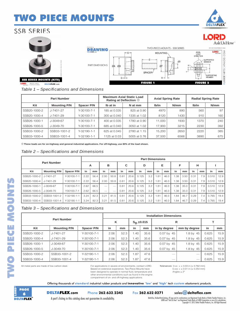
Page 72 of 124TWO-PIECE MOUNTS
SSB Series
Table 1 – Specifi cations and Dimensions
These loads are for on-highway and general industrial applications. For off-highway, use 80% of the load shown.
Part Number Maximum Axial Static Load Rating at Defl ection Axial Spring Rate Radial Spring Rate
Kit Mounting P/N Spacer P/N lb at in N at mm lb/in N/mm lb/in N/mm
SSB20-1000-2 J-7401-27 Y-30100-7-1 185 at 0.035 825 at 0.90 4970 890 560 97
SSB20-1000-4 J-7401-29 Y-30100-7-1 300 at 0.040 1335 at 1.02 8120 1430 910 160
SSB26-1000-1 J-3049-67 Y-30100-7-1 400 at 0.035 1780 at 0.90 11,000 1930 1370 240
SSB26-1000-5 J-3049-70 Y-30100-7-1 685 at 0.040 3050 at 1.02 17,900 3215 2230 392
SSB33-1000-2 SSB33-1001-2 Y-32190-1-1 625 at 0.045 2780 at 1.15 15,200 2650 2220 385
SSB33-1000-4 SSB33-1001-4 Y-32190-1-1 1125 at 0.03 5005 at 0.76 37,500 6566 3890 675
Table 2 – Specifi cations and Dimensions
Part NumberPart Dimensions
A B C D E F H I
Kit Mounting P/N Spacer P/N in mm in mm in mm in mm in mm in mm in mm in mm
SSB20-1000-2 J-7401-27 Y-30100-7-1 2.22 56.4 2.00 50.8 0.81 20.6 0.125 3.2 1.81 46.0 1.38 3.50 0.31 7.9 0.510 12.9
SSB20-1000-4 J-7401-29 Y-30100-7-1 2.22 56.4 2.00 50.8 0.81 20.6 0.125 3.2 1.81 46.0 1.38 3.50 0.31 7.9 0.510 12.9
SSB26-1000-1 J-3049-67 Y-30100-7-1 2.62 66.5 — — 0.81 20.6 0.125 3.2 1.81 46.0 1.38 35.0 0.31 7.9 0.510 12.9
SSB26-1000-5 J-3049-70 Y30100-7-1 2.62 66.5 — — 0.81 20.6 0.125 3.2 1.81 46.0 1.38 35.0 0.31 7.9 0.510 12.9
SSB33-1000-2 SSB33-1001-2 Y-32190-1-1 3.24 82.3 3.21 81.5 0.81 20.6 0.125 3.2 1.81 46.0 1.84 46.7 0.29 7.4 0.765 19.4
SSB33-1000-4 SSB33-1001-4 Y-32190-1-1 3.24 82.3 3.21 81.5 0.81 20.6 0.125 3.2 1.81 46.0 1.84 46.7 0.29 7.4 0.765 19.4
Table 3 – Specifi cations and Dimensions
Part NumberInstallation Dimensions
K SD ±0.015 R T
Kit Mounting P/N Spacer P/N in mm in mm in by degree mm by degree in mm
SSB20-1000-2 J-7401-27 Y-30100-7-1 2.06 52.3 1.40 35.6 0.07 by 45 1.8 by 45 0.625 15.9
SSB20-1000-4 J-7401-29 Y-30100-7-1 2.06 52.3 1.40 35.6 0.07 by 45 1.8 by 45 0.625 15.9
SSB26-1000-1 J-3049-67 Y-30100-7-1 2.06 52.3 1.40 35.6 0.07 by 45 1.8 by 45 0.625 15.9
SSB26-1000-5 J-3049-70 Y-30100-7-1 2.06 52.3 1.40 35.6 0.07 by 45 1.8 by 45 0.625 15.9
SSB33-1000-2 SSB33-1001-2 Y-32190-1-1 2.06 52.3 1.87 47.6 — — 0.625 15.9
SSB33-1000-4 SSB33-1001-4 Y-32190-1-1 2.06 52.3 1.87 47.6 — — 0.625 15.9
All metal parts are made of low carbon steel. For applications in severe oil environments, contact LORD. Based on extensive experience, Two-Piece Mounts have been designed to operate in normal fl uid, temperature and other environmental conditions such as found in the engine compartment of on- and off-highway applications.
Tolerances: 0.xx = ± 0.03 in (± 0.762 mm) 0.xxx = ± 0.01 in (± 0.254 mm) Angles ± 2°
SSB SERIES
A part’s listing in this catalog does not guarantee its availability.To download/print the most current catalog, go to www.lordfulfi llment.com/upload/PC7000.pdf. Rev.1 10/08
Page 72 of 124TWO-PIECE MOUNTS
SSB Series
Table 1 – Specifi cations and Dimensions
These loads are for on-highway and general industrial applications. For off-highway, use 80% of the load shown.
Part Number Maximum Axial Static Load Rating at Defl ection Axial Spring Rate Radial Spring Rate
Kit Mounting P/N Spacer P/N lb at in N at mm lb/in N/mm lb/in N/mm
SSB20-1000-2 J-7401-27 Y-30100-7-1 185 at 0.035 825 at 0.90 4970 890 560 97
SSB20-1000-4 J-7401-29 Y-30100-7-1 300 at 0.040 1335 at 1.02 8120 1430 910 160
SSB26-1000-1 J-3049-67 Y-30100-7-1 400 at 0.035 1780 at 0.90 11,000 1930 1370 240
SSB26-1000-5 J-3049-70 Y-30100-7-1 685 at 0.040 3050 at 1.02 17,900 3215 2230 392
SSB33-1000-2 SSB33-1001-2 Y-32190-1-1 625 at 0.045 2780 at 1.15 15,200 2650 2220 385
SSB33-1000-4 SSB33-1001-4 Y-32190-1-1 1125 at 0.03 5005 at 0.76 37,500 6566 3890 675
Table 2 – Specifi cations and Dimensions
Part NumberPart Dimensions
A B C D E F H I
Kit Mounting P/N Spacer P/N in mm in mm in mm in mm in mm in mm in mm in mm
SSB20-1000-2 J-7401-27 Y-30100-7-1 2.22 56.4 2.00 50.8 0.81 20.6 0.125 3.2 1.81 46.0 1.38 3.50 0.31 7.9 0.510 12.9
SSB20-1000-4 J-7401-29 Y-30100-7-1 2.22 56.4 2.00 50.8 0.81 20.6 0.125 3.2 1.81 46.0 1.38 3.50 0.31 7.9 0.510 12.9
SSB26-1000-1 J-3049-67 Y-30100-7-1 2.62 66.5 — — 0.81 20.6 0.125 3.2 1.81 46.0 1.38 35.0 0.31 7.9 0.510 12.9
SSB26-1000-5 J-3049-70 Y30100-7-1 2.62 66.5 — — 0.81 20.6 0.125 3.2 1.81 46.0 1.38 35.0 0.31 7.9 0.510 12.9
SSB33-1000-2 SSB33-1001-2 Y-32190-1-1 3.24 82.3 3.21 81.5 0.81 20.6 0.125 3.2 1.81 46.0 1.84 46.7 0.29 7.4 0.765 19.4
SSB33-1000-4 SSB33-1001-4 Y-32190-1-1 3.24 82.3 3.21 81.5 0.81 20.6 0.125 3.2 1.81 46.0 1.84 46.7 0.29 7.4 0.765 19.4
Table 3 – Specifi cations and Dimensions
Part NumberInstallation Dimensions
K SD ±0.015 R T
Kit Mounting P/N Spacer P/N in mm in mm in by degree mm by degree in mm
SSB20-1000-2 J-7401-27 Y-30100-7-1 2.06 52.3 1.40 35.6 0.07 by 45 1.8 by 45 0.625 15.9
SSB20-1000-4 J-7401-29 Y-30100-7-1 2.06 52.3 1.40 35.6 0.07 by 45 1.8 by 45 0.625 15.9
SSB26-1000-1 J-3049-67 Y-30100-7-1 2.06 52.3 1.40 35.6 0.07 by 45 1.8 by 45 0.625 15.9
SSB26-1000-5 J-3049-70 Y-30100-7-1 2.06 52.3 1.40 35.6 0.07 by 45 1.8 by 45 0.625 15.9
SSB33-1000-2 SSB33-1001-2 Y-32190-1-1 2.06 52.3 1.87 47.6 — — 0.625 15.9
SSB33-1000-4 SSB33-1001-4 Y-32190-1-1 2.06 52.3 1.87 47.6 — — 0.625 15.9
All metal parts are made of low carbon steel. For applications in severe oil environments, contact LORD. Based on extensive experience, Two-Piece Mounts have been designed to operate in normal fl uid, temperature and other environmental conditions such as found in the engine compartment of on- and off-highway applications.
Tolerances: 0.xx = ± 0.03 in (± 0.762 mm) 0.xxx = ± 0.01 in (± 0.254 mm) Angles ± 2°

DELTAFLEX®
Offering thousands of standard industrial rubber products and innovative “low” and “high” tech custom elastomeric products.
DELTAFLEX®
PAGE7DELTAFLEX.com Phone 262.632.2345 Fax 262.632.0271 [email protected]
LO
RD
®
TWO PIECE MOUNTSTW
O P
IECE M
OU
NTS
A part’s listing in this catalog does not guarantee its availability.DeltaFlex, RubberPartsCatalog, df Logo and its combinations are Registered Trade Marks of Delta Flexible Products, Inc.
Copyright © 2012 Delta Flexible Products, Inc. All Right ReservedLORD and “Ask Us How” are Registered Trade Marks of LORD Corporation or one of its subsidiaries.
A part’s listing in this catalog does not guarantee its availability.To download/print the most current catalog, go to www.lordfulfi llment.com/upload/PC7000.pdf. Rev.1 10/08
Page 73 of 124TWO-PIECE MOUNTS
Figure 1 – Part Dimensions
Figure 2 – Installation View(Shown Under No Load)
Table 4 – Specifi cations and Dimensions
* For tightening torque information, refer to Tightening Torque Charts section.
Part NumberRecommended Bolt Information*
Size Grade or Class
Kit Mounting P/N Spacer P/N English Metric SAE J429 SAE J1199
SSB20-1000-2 J-7401-27 Y-30100-7-1 1/2 M12 2 5.8
SSB20-1000-4 J-7401-29 Y-30100-7-1 1/2 M12 2 5.8
SSB26-1000-1 J-3049-67 Y-30100-7-1 1/2 M12 2 5.8
SSB26-1000-5 J-3049-70 Y-30100-7-1 1/2 M12 2 5.8
SSB33-1000-2 SSB33-1001-2 Y-32190-1-1 3/4 M18 8 10.9
SSB33-1000-4 SSB33-1001-4 Y-32190-1-1 3/4 M18 8 10.9
SSB SERIES
Need pricing or current inventory?
CALL US @ 800.657.0747Ask for Quoting

DELTAFLEX®
Offering thousands of standard industrial rubber products and innovative “low” and “high” tech custom elastomeric products.
DELTAFLEX®
PAGE8L
OR
D®
DELTAFLEX.com Phone 262.632.2345 Fax 262.632.0271 [email protected]
TWO PIECE MOUNTSTW
O P
IECE
MO
UN
TS
A part’s listing in this catalog does not guarantee its availability. DeltaFlex, RubberPartsCatalog, df Logo and its combinations are Registered Trade Marks of Delta Flexible Products, Inc.
Copyright © 2012 Delta Flexible Products, Inc. All Right ReservedLORD and “Ask Us How” are Registered Trade Marks of LORD Corporation or one of its subsidiaries.
A part’s listing in this catalog does not guarantee its availability.To download/print the most current catalog, go to www.lordfulfi llment.com/upload/PC7000.pdf. Rev.1 10/08
Page 74 of 124TWO-PIECE MOUNTS
CB-2200 Series
Table 1 – Specifi cations and Dimensions
Maximum Axial Load at Defl ection Based on Plate Thickness
Part Elastomer Color Part Elastomer Color T - Thick Support Plate T - Thin Support Plate Number � Code Number � Code (Recommended) (Optional)
� � � � Thickness - T Load/Defl ection � Thickness - T Load/Defl ection �
in mm lb at in N at mm in mm lb at in N at mm
CB-2201-1 NR R CB-2201-11 OR R & W 0.375 9.5 40 at 0.05 178 at 1.3 0.375 9.5 40 at 0.05 178 at 1.3CB-2201-2 NR Y CB-2201-12 OR Y & W 0.375 9.5 90 at 0.05 400 at 1.3 0.375 9.5 90 at 0.05 400 at 1 3CB-2201-3 NR G CB-2201-13 OR G & W 0.375 9.5 140 at 0.05 623 at 1.3 0.375 9.5 140 at 0.05 623 at 1.3CB-2201-4 NR B CB-2201-14 OR B & W 0.375 9.5 250 at 0.05 1112 at 1.3 0.375 9.5 250 at 0.05 1112 at 1.3— — — CB-2201-15 OR P & W 0.375 9.5 300 at 0.05 1334 at 1.3 0.375 9.5 300 at 0.05 1334 at 1.3
CB-2202-1 NR R CB-2202-11 OR R & W 0.563 14.3 130 at 0.07 578 at 1.8 0.500 12.7 60 at 0.05 267 at 1.3CB-2202-2 NR Y CB-2202-12 OR Y & W 0.563 14.3 175 at 0.07 778 at 1.8 0.500 12.7 120 at 0.05 534 at 1.3CB-2202-3 NR G CB-2202-13 OR G & W 0.563 14.3 240 at 0.07 1068 at 1.8 0.500 12.7 160 at 0.05 712 at 1.3CB-2202-4 NR B CB-2202-14 OR B & W 0.563 14.3 380 at 0.07 1690 at 1.8 0.500 12.7 260 at 0.05 1157 at 1.3CB-2202-5 NR P CB-2202-15 OR P & W 0.563 14.3 630 at 0.07 2802 at 1.8 0.500 12.7 380 at 0.05 1690 at 1.3
CB-2203-1 NR R — — — 0.875 22.2 175 at 0.085 780 at 2.2 0.750 19.1 100 at 0.05 440 at 1.3— — — CB-2203-12 OR Y & W 0.875 22.2 300 at 0.085 1330 at 2.2 0.750 19.1 150 at 0.05 670 at 1.3CB-2203-3 NR G CB-2203-13 OR G & W 0.875 22.2 400 at 0.085 1780 at 2.2 0.750 19.1 225 at 0.05 1000 at 1.3CB-2203-4 NR B CB-2203-14 OR B & W 0.875 22.2 500 at 0.085 2220 at 2.2 0.750 19.1 325 at 0.05 1450 at 1.3CB-2203-5 NR P CB-2203-15 OR P & W 0.875 22.2 725 at 0.085 3220 at 2.2 0.750 19.1 450 at 0.05 2000 at 1.3
CB-2204-1 NR R CB-2204-11 OR R & W 1.125 28.6 400 at 0.09 1780 at 2.3 1.000 25.4 200 at 0.05 890 at 1.3CB-2204-2 NR Y CB-2204-12 OR Y & W 1.125 28.6 550 at 0.09 2450 at 2.3 1.000 25.4 300 at 0.05 1330 at 1.3CB-2204-3 NR G CB-2204-13 OR G & W 1.125 28.6 700 at 0.09 3110 at 2.3 1.000 25.4 400 at 0.05 1780 at 1.3CB-2204-4 NR B CB-2204-14 OR B & W 1.125 28.6 850 at 0.09 3780 at 2.3 1.000 25.4 500 at 0.05 2220 at 1.3CB-2204-5 NR P CB-2204-15 OR P & W 1.125 28.6 1000 at 0.09 4450 at 2.3 1.000 25.4 600 at 0.05 2670 at 1.3
CB-2205-1 NR R CB-2205-11 OR R & W 1.250 31.8 900 at 0.09 4000 at 2.3 1.000 25.4 300 at 0.05 1334 at 1.3CB-2205-2 NR Y CB-2205-12 OR Y & W 1.250 31.8 1200 at 0.09 5340 at 2.3 1.000 25.4 500 at 0.05 2224 at 1.3CB-2205-3 NR G — — — 1.250 31.8 1500 at 0.09 6670 at 2.3 1.000 25.4 700 at 0.05 3114 at 1.3CB-2205-4 NR B CB-2205-14 OR B & W 1.250 31.8 1800 at 0.09 8010 at 2.3 1.000 25.4 900 at 0.05 4003 at 1.3CB-2205-5 NR P CB-2205-15 OR P & W 1.250 31.8 2100 at 0.09 9340 at 2.3 1.000 25.4 1100 at 0.05 5338 at 1.3CB-2205-7 NR Y & Y — OR Y & Y & W 1.250 31.8 1600 at 0.09 7117 at 2.3 1.000 25.4 775 at 0.05 3447 at 1.3— — — CB-2205-18 OR G & G & W 1.250 31.8 2200 at 0.09 9786 at 2.3 1.000 25.4 1000 at.0 05 4448 at 1.3CB-2205-9 NR B & B CB-2205-19 OR B & B & W 1.250 31.8 2825 at 0.09 12566 at 2.3 1.000 25.4 1425 at 0.05 6339 at 1.3CB-2205-10 NR P & P CB-2205-20 OR P & P & W 1.250 31.8 3450 at 0.09 15346 at 2.3 1.000 25.4 1800 at 0.05 8007 at 1.3
Mounts only supplied by LORD.
� One P/N contains one top and one bottom mount only.
� NR = Natural Rubber OR = Oil-Resistant Elastomer - Neoprene
� Color Codes: R = Red Y = Yellow G = Green B = Blue P = Purple W = White
� These loads are for on-highway and general industrial applications. For off-highway, use 90% of the load shown.
Caution: When using the maximum bolt torque listed a hardened (RB95) rebound washer and support member should be used. A hardened washer may be placed under the supported member when the supported member is not hardened.
Table 2 – Specifi cations
SeriesNumber
Recommended Bolt Information*
Size Grade or Class
English Metric SAE J429 SAE J1199
CB-2201 3/8 M10 5 5.8
CB-2202 1/2 M12 8 10.9
CB-2203 5/8 M16 8 10.9
CB-2204 7/8 M20 8 10.9
CB-2205 1.0 M24 8 10.9
* For tightening torque information, refer to Tightening Torque Charts section.
Series Number
Washer Part
Number
O.D. I.D. Thickness
in mm in mm in mm
CB-2201 J-2049-89 1.56 39.6 0.391 9.9 0.09 2.3
CB-2202 J-2049-90 2.13 54.1 0.530 13.5 0.134 3.4
CB-2203 J-2049-91 2.81 71.4 0.657 16.7 0.188 4.8
CB-2204 J-2049-92 3.88 98.6 0.938 23.8 0.250 6.4
CB-2205 J-2049-93 5.25 133.4 1.063 27.0 0.375 9.5
Table 3 – Washer Specifi cations
Material is SAE 1008-1015 steel zinc plated and chromate treated.
CB-2200 SERIES
A part’s listing in this catalog does not guarantee its availability.To download/print the most current catalog, go to www.lordfulfi llment.com/upload/PC7000.pdf. Rev.1 10/08
Page 74 of 124TWO-PIECE MOUNTS
CB-2200 Series
Table 1 – Specifi cations and Dimensions
Maximum Axial Load at Defl ection Based on Plate Thickness
Part Elastomer Color Part Elastomer Color T - Thick Support Plate T - Thin Support Plate Number � Code Number � Code (Recommended) (Optional)
� � � � Thickness - T Load/Defl ection � Thickness - T Load/Defl ection �
in mm lb at in N at mm in mm lb at in N at mm
CB-2201-1 NR R CB-2201-11 OR R & W 0.375 9.5 40 at 0.05 178 at 1.3 0.375 9.5 40 at 0.05 178 at 1.3CB-2201-2 NR Y CB-2201-12 OR Y & W 0.375 9.5 90 at 0.05 400 at 1.3 0.375 9.5 90 at 0.05 400 at 1 3CB-2201-3 NR G CB-2201-13 OR G & W 0.375 9.5 140 at 0.05 623 at 1.3 0.375 9.5 140 at 0.05 623 at 1.3CB-2201-4 NR B CB-2201-14 OR B & W 0.375 9.5 250 at 0.05 1112 at 1.3 0.375 9.5 250 at 0.05 1112 at 1.3— — — CB-2201-15 OR P & W 0.375 9.5 300 at 0.05 1334 at 1.3 0.375 9.5 300 at 0.05 1334 at 1.3
CB-2202-1 NR R CB-2202-11 OR R & W 0.563 14.3 130 at 0.07 578 at 1.8 0.500 12.7 60 at 0.05 267 at 1.3CB-2202-2 NR Y CB-2202-12 OR Y & W 0.563 14.3 175 at 0.07 778 at 1.8 0.500 12.7 120 at 0.05 534 at 1.3CB-2202-3 NR G CB-2202-13 OR G & W 0.563 14.3 240 at 0.07 1068 at 1.8 0.500 12.7 160 at 0.05 712 at 1.3CB-2202-4 NR B CB-2202-14 OR B & W 0.563 14.3 380 at 0.07 1690 at 1.8 0.500 12.7 260 at 0.05 1157 at 1.3CB-2202-5 NR P CB-2202-15 OR P & W 0.563 14.3 630 at 0.07 2802 at 1.8 0.500 12.7 380 at 0.05 1690 at 1.3
CB-2203-1 NR R — — — 0.875 22.2 175 at 0.085 780 at 2.2 0.750 19.1 100 at 0.05 440 at 1.3— — — CB-2203-12 OR Y & W 0.875 22.2 300 at 0.085 1330 at 2.2 0.750 19.1 150 at 0.05 670 at 1.3CB-2203-3 NR G CB-2203-13 OR G & W 0.875 22.2 400 at 0.085 1780 at 2.2 0.750 19.1 225 at 0.05 1000 at 1.3CB-2203-4 NR B CB-2203-14 OR B & W 0.875 22.2 500 at 0.085 2220 at 2.2 0.750 19.1 325 at 0.05 1450 at 1.3CB-2203-5 NR P CB-2203-15 OR P & W 0.875 22.2 725 at 0.085 3220 at 2.2 0.750 19.1 450 at 0.05 2000 at 1.3
CB-2204-1 NR R CB-2204-11 OR R & W 1.125 28.6 400 at 0.09 1780 at 2.3 1.000 25.4 200 at 0.05 890 at 1.3CB-2204-2 NR Y CB-2204-12 OR Y & W 1.125 28.6 550 at 0.09 2450 at 2.3 1.000 25.4 300 at 0.05 1330 at 1.3CB-2204-3 NR G CB-2204-13 OR G & W 1.125 28.6 700 at 0.09 3110 at 2.3 1.000 25.4 400 at 0.05 1780 at 1.3CB-2204-4 NR B CB-2204-14 OR B & W 1.125 28.6 850 at 0.09 3780 at 2.3 1.000 25.4 500 at 0.05 2220 at 1.3CB-2204-5 NR P CB-2204-15 OR P & W 1.125 28.6 1000 at 0.09 4450 at 2.3 1.000 25.4 600 at 0.05 2670 at 1.3
CB-2205-1 NR R CB-2205-11 OR R & W 1.250 31.8 900 at 0.09 4000 at 2.3 1.000 25.4 300 at 0.05 1334 at 1.3CB-2205-2 NR Y CB-2205-12 OR Y & W 1.250 31.8 1200 at 0.09 5340 at 2.3 1.000 25.4 500 at 0.05 2224 at 1.3CB-2205-3 NR G — — — 1.250 31.8 1500 at 0.09 6670 at 2.3 1.000 25.4 700 at 0.05 3114 at 1.3CB-2205-4 NR B CB-2205-14 OR B & W 1.250 31.8 1800 at 0.09 8010 at 2.3 1.000 25.4 900 at 0.05 4003 at 1.3CB-2205-5 NR P CB-2205-15 OR P & W 1.250 31.8 2100 at 0.09 9340 at 2.3 1.000 25.4 1100 at 0.05 5338 at 1.3CB-2205-7 NR Y & Y — OR Y & Y & W 1.250 31.8 1600 at 0.09 7117 at 2.3 1.000 25.4 775 at 0.05 3447 at 1.3— — — CB-2205-18 OR G & G & W 1.250 31.8 2200 at 0.09 9786 at 2.3 1.000 25.4 1000 at.0 05 4448 at 1.3CB-2205-9 NR B & B CB-2205-19 OR B & B & W 1.250 31.8 2825 at 0.09 12566 at 2.3 1.000 25.4 1425 at 0.05 6339 at 1.3CB-2205-10 NR P & P CB-2205-20 OR P & P & W 1.250 31.8 3450 at 0.09 15346 at 2.3 1.000 25.4 1800 at 0.05 8007 at 1.3
Mounts only supplied by LORD.
� One P/N contains one top and one bottom mount only.
� NR = Natural Rubber OR = Oil-Resistant Elastomer - Neoprene
� Color Codes: R = Red Y = Yellow G = Green B = Blue P = Purple W = White
� These loads are for on-highway and general industrial applications. For off-highway, use 90% of the load shown.
Caution: When using the maximum bolt torque listed a hardened (RB95) rebound washer and support member should be used. A hardened washer may be placed under the supported member when the supported member is not hardened.
Table 2 – Specifi cations
SeriesNumber
Recommended Bolt Information*
Size Grade or Class
English Metric SAE J429 SAE J1199
CB-2201 3/8 M10 5 5.8
CB-2202 1/2 M12 8 10.9
CB-2203 5/8 M16 8 10.9
CB-2204 7/8 M20 8 10.9
CB-2205 1.0 M24 8 10.9
* For tightening torque information, refer to Tightening Torque Charts section.
Series Number
Washer Part
Number
O.D. I.D. Thickness
in mm in mm in mm
CB-2201 J-2049-89 1.56 39.6 0.391 9.9 0.09 2.3
CB-2202 J-2049-90 2.13 54.1 0.530 13.5 0.134 3.4
CB-2203 J-2049-91 2.81 71.4 0.657 16.7 0.188 4.8
CB-2204 J-2049-92 3.88 98.6 0.938 23.8 0.250 6.4
CB-2205 J-2049-93 5.25 133.4 1.063 27.0 0.375 9.5
Table 3 – Washer Specifi cations
Material is SAE 1008-1015 steel zinc plated and chromate treated.

DELTAFLEX®
Offering thousands of standard industrial rubber products and innovative “low” and “high” tech custom elastomeric products.
DELTAFLEX®
PAGE9DELTAFLEX.com Phone 262.632.2345 Fax 262.632.0271 [email protected]
LO
RD
®
TWO PIECE MOUNTSTW
O P
IECE M
OU
NTS
A part’s listing in this catalog does not guarantee its availability.DeltaFlex, RubberPartsCatalog, df Logo and its combinations are Registered Trade Marks of Delta Flexible Products, Inc.
Copyright © 2012 Delta Flexible Products, Inc. All Right ReservedLORD and “Ask Us How” are Registered Trade Marks of LORD Corporation or one of its subsidiaries.
A part’s listing in this catalog does not guarantee its availability.To download/print the most current catalog, go to www.lordfulfi llment.com/upload/PC7000.pdf. Rev.1 10/08
Page 75 of 124TWO-PIECE MOUNTS
Figure 2 – Installation View(Shown Under No Load)
Table 4 – Specifi cations and Dimensions
Figure 1 – Part Dimensions
Series Number
Part Dimensions H Reference Installation Dimensions
A B C Ref. D E F GThick
Support Plate
Thin Support
PlateSD R Ref.
in mm in mm in mm in mm in mm in mm in mm in mm in mm in mm in mm
CB-2201 1.34/1.28 33.3 0.407/
0.396 10.2 0.58 14.7 1.28/1.22 31.8 0.82/
0.76 20.1 0.515/0.455 12.3 0.62/
0.58 15.2 0.44 11.2 0.44 11.2 0.77/0.73 19.1 0.04 1.0
CB-2202 1.91/1.85 47.8 0.547/
0.517 13.5 0.83 21.1 1.97/1.91 49.3 1.33/
1.27 33.0 0.81/0.75 19.8 0.845/
0.825 21.2 0.69 17.5 0.72 18.3 1.27/1.23 31.8 0.06 1.5
CB-2203 2.58/2.52 64.8 0.672/
0.642 16.7 0.97 24.6 2.46/2.40 61.7 1.61/
1.55 40.1 0.93/0.87 22.9 0.99/
0.95 24.8 0.78 19.8 0.84 21.3 1.52/1.48 38.1 0.09 2.3
CB-2204 3.49/3.43 87.9 0.958/
0.938 24.1 1.45 36.8 2.91/2.85 73.0 2.33/
2.27 58.4 1.03/0.97 25.4 1.50/
1.46 37.6 0.88 22.4 0.94 23.9 2.27/2.23 57.2 0.12 3.0
CB-2205 4.94/4.82 124.0 1.078/
1.048 27.0 1.50 38.1 3.41/3.35 85.9 2.58/
2.52 64.8 1.28/1.22 31.8 1.52/
1.46 37.8 1.06 26.9 1.19 30.2 2.52/2.48 63.5 0.12 3.0
CB-2200 SERIES
Need pricing or current inventory? CALL US @ 800.657.0747 Ask for Quoting
A part’s listing in this catalog does not guarantee its availability.To download/print the most current catalog, go to www.lordfulfi llment.com/upload/PC7000.pdf. Rev.1 10/08
Page 75 of 124TWO-PIECE MOUNTS
Figure 2 – Installation View(Shown Under No Load)
Table 4 – Specifi cations and Dimensions
Figure 1 – Part Dimensions
Series Number
Part Dimensions H Reference Installation Dimensions
A B C Ref. D E F GThick
Support Plate
Thin Support
PlateSD R Ref.
in mm in mm in mm in mm in mm in mm in mm in mm in mm in mm in mm
CB-2201 1.34/1.28 33.3 0.407/
0.396 10.2 0.58 14.7 1.28/1.22 31.8 0.82/
0.76 20.1 0.515/0.455 12.3 0.62/
0.58 15.2 0.44 11.2 0.44 11.2 0.77/0.73 19.1 0.04 1.0
CB-2202 1.91/1.85 47.8 0.547/
0.517 13.5 0.83 21.1 1.97/1.91 49.3 1.33/
1.27 33.0 0.81/0.75 19.8 0.845/
0.825 21.2 0.69 17.5 0.72 18.3 1.27/1.23 31.8 0.06 1.5
CB-2203 2.58/2.52 64.8 0.672/
0.642 16.7 0.97 24.6 2.46/2.40 61.7 1.61/
1.55 40.1 0.93/0.87 22.9 0.99/
0.95 24.8 0.78 19.8 0.84 21.3 1.52/1.48 38.1 0.09 2.3
CB-2204 3.49/3.43 87.9 0.958/
0.938 24.1 1.45 36.8 2.91/2.85 73.0 2.33/
2.27 58.4 1.03/0.97 25.4 1.50/
1.46 37.6 0.88 22.4 0.94 23.9 2.27/2.23 57.2 0.12 3.0
CB-2205 4.94/4.82 124.0 1.078/
1.048 27.0 1.50 38.1 3.41/3.35 85.9 2.58/
2.52 64.8 1.28/1.22 31.8 1.52/
1.46 37.8 1.06 26.9 1.19 30.2 2.52/2.48 63.5 0.12 3.0
TECHNICAL
DRAWINGDELTAFLEX.com
™

DELTAFLEX®
Offering thousands of standard industrial rubber products and innovative “low” and “high” tech custom elastomeric products.
DELTAFLEX®
PAGE10L
OR
D®
DELTAFLEX.com Phone 262.632.2345 Fax 262.632.0271 [email protected]
TWO PIECE MOUNTSTW
O P
IECE
MO
UN
TS
A part’s listing in this catalog does not guarantee its availability. DeltaFlex, RubberPartsCatalog, df Logo and its combinations are Registered Trade Marks of Delta Flexible Products, Inc.
Copyright © 2012 Delta Flexible Products, Inc. All Right ReservedLORD and “Ask Us How” are Registered Trade Marks of LORD Corporation or one of its subsidiaries.
Need assistance with selecting the right mount for your application?CALL US @ 800.657.0747 Ask for Engineering
NOTES:
SKETCH:

APP
LICA
TIO
N S
ELEC
TIO
N G
UID
E
1515
16t
h St
reet
• R
acin
e, W
I 534
03 •
Tel
epho
ne: 4
14/6
32-2
345
• To
ll Fr
ee: 8
00/6
57-0
747
• FA
X: 4
14/6
32-0
271
TEC
HN
ICAL
DATA
OFF
ERIN
G T
HO
USA
NDS
OF
STAN
DARD
INDU
STRI
AL R
UBB
ER P
RODU
CTS
AN
D IN
NO
VATI
VE “
LOW
” AN
D “H
IGH
” TE
CH
CU
STO
M E
LAST
OM
ERIC
PRO
DUC
TS.
Actu
ator
s
Cabs
Comp
uter
& A
ccess
ories
Covn
eyor
s
Delic
ate
Equip
ment
Driv
e Lin
es
Electr
onics
Engi
nes
Engi
ne G
en/P
umps
sets
Fans
/Blo
wer
s
Heat
ing/C
oolin
g Un
its
Inst
rume
nts &
Gau
ges
Mac
hiner
y - P
unch
, Prin
ting,
Milli
ng, P
ress
es
Mot
ors E
lectri
c
Pump
s. Co
mpre
ssor
s
Shak
ers/
Vibr
ator
s
Vehic
le Ac
cess
ories
Shipp
ing C
onta
iners
Grommet
Isolat
ors
Standa
rd
Platef
orms Pla
teform
s HeavyDu
ty Multi-P
lane Ce
nterB
onde
dMounts
CB-11
00ser
ies CB-11
80ser
ies CBAser
ies
CBA-50
series STA
series
Safetie
dtubefor
ms
Conica
lMoun
ts
Hyste
c™Mou
nts
Two-P
ieceMou
nts
CBB/CB
Cseries SSB
series
CB-22
00ser
ies Bushi
ngs Cen
terbon
ded Square
Sand
wichMou
nts
Metric
Small
Medium
Large
Machine
ryMou
nts
Lattice
Chan-L
-Moun
ts
Levelin
gInd
ustria
l RodEnd
s Coup
lings She
arSpo
oltype
Bushi
ngtyp
e LCRLCD
Small
Industr
ialeng
inemoun
ts
••
••
••
••
••
••
••
••
••
••
••
••
••
••
••
••
••
••
••
••
••
••
••
••
••
••
••
••
••
••
••
••
••
••
••
••
••
••
••
••
••
••
••
••
••
••
••
••
••
••
••
••
••
••
••
••
••
••
••
••
••
••
••
••
••
••
••
••
••
••
••
••
••
••
••
••
••
••
••
••
••
••
••
••
••
••
••
••
••
••
••
••
••
••
••
••
••
••
••
••
••
••
••
••
••
••
••
••
••
••
••
••
••
••
••
••
••
••
••
••
••
••
••
••
••
••
••
••
••
••
••
•
RU
BB
ER
PA
RTS
CA
TALO
G® .c
om

VIBRATION, SHOCK & MOTION CONTROL
Values stated herein represent typical values as not all tests are run on each lot of material produced. For formalized product specifications or specific products end uses, contact Engineering @ 800.657.0747.
Information provided herein is based upon tests believed to be reliable. In as much as DELTAFLEX and/or LORD Corporation has no control over the manner in which others may use this information, it does not guarantee the results to be obtained. In addition, DELTAFLEX and/or LORD Corporation does not guarantee the performance of the product or the results obtained from the use of the product or this information where the product has been repacked by any third party, includ-ing but not limited to any product end-user. Nor does the company make any express or implied warranty of merchantability or fitness for a particular purpose concerning the effects or results of such use.
Headquarters1515 16th StreetRacine, WI 53403
DELTAFLEX.com™
Phone 262.632.2345Customer Service 800.657.0747
Fax 262.632.0271
Flex-Bolt and “Ask Us How” are trademarks of LORD corporation or one of its subsidiariesDeltaFlex, the df triangle, RubberPartsCatalog and its logos are registered trademarks of Delta Flexible Products, Inc.
A parts listing in this catalog does not guarantee its availability. To download the most current version to go to RubberPartsCatalog.com
Manufacturing
Distribution
Vibration Mounts
Grommets
Bumpers
Gaskets
Bushings
Stock & Custom Parts
Molded & Extruded
Military Grommets
End Caps
Adhesive Backed Bumpers
Lab Stoppers
Tips & Caps
Cord Stock
Suction Cups
Rubber Washer
O-Rings
Sheet, Sponge & Matting
Custom Fabrication
Blanket Service
Inventory Management & Releases
RUBBER PARTS CATALOG®.com