two-dimensional axisymmetric electromechanical response of
TRANSCRIPT

© 2010 IAU, Arak Branch. All rights reserved.
Journal of Solid Mechanics Vol. 2, No. 4 (2010) pp. xxx-xxx
Two-dimensional Axisymmetric Electromechanical Response of Piezoelectric, Functionally Graded and Layered Composite Cylinders
T. Kant1, P. Desai2,* 1Institute Chair Professor, Department of Civil Engineering, Indian Institute of Technology Bombay, Powai, Mumbai, India 2Manager (Design), S N Bhobe and Associates, Navi Mumbai, Mumbai, India
Received 26 December 2010; accepted 31December 2010
ABSTRACT
A mixed semi-analytical cum numerical approach is presented in this paper which accounts for the coupled mechanical and electrical response of piezoelectric, functionally graded (FG) and layered composite hollow circular cylinders of finite length. Under axisymmetric mechanical and electrical loadings, the three-dimensional problem (3D) gets reduced to a two-dimensional (2D) plane strain problem of elasticity. The 2D problem is further simplified and reduced to a one-dimensional (1D) by assuming an analytical solution in longitudinal direction (z) in terms of Fourier series expansion which satisfies the simply (diaphragm) supported boundary conditions exactly at the two ends z = 0, l. Fundamental (basic) dependent variables are chosen in the radial direction (thickness coordinate) of the cylinder. The resulting mathematical model is cast in the form of first order simultaneous ordinary differential equations which are integrated through an effective numerical integration technique by first transforming the BVP into a set of initial value problems (IVPs). The cylinder is subjected to internal/external pressurized mechanical and an electrical loading. Finally, numerical results are obtained which govern the active and sensory response of piezoelectric and FG cylinders. Numerical results are compared for their accuracy with available results. New results of finite length cylinders are generated and presented for future reference.
© 2010 IAU, Arak Branch. All rights reserved.
Keywords: Finite length cylinder; FGM, Laminated composites; Piezoelectricity; Boundary value problem; Elasticity theory.
1 INTRODUCTION
YLINDERS made of composites have seen an ever increasing use in the process industry during the last twenty five years. Their use as a material of choice for pressure vessels and components is due to the fact that
they possess longer life in a corrosive environment, low weight but high strength and stiffness, and the capability to tailor directional strength properties to design needs. The development of piezoelectric and graded composite materials offers great potential for use in cylindrical vessels in advanced aerospace structural applications. The basic shape of piezoelectric device is circular cylinder which is used as transducers, which can reflect and receive waves from the media when it is pressurized. Also, it converts the electrical pulses to mechanical energy and mechanical energy to electrical pulses when pressurized. This basic device has many other applications like ultrasound, ground penetrating radar, which is extremely useful. It is very important to understand the behavior of such devices before it is used for engineering design. In view of this, present study is focused on such cylinders which are made up of ______ * Corresponding author. Tel.: +919867320596 .
E-mail address: [email protected] (P. Desai).
C
2 Two-dimensional Axisymmetric Electromechanical Response …
© 2010 IAU, Arak Branch
piezoelectric/graded materials and polarized in radial direction, which is subjected to electrical, mechanical and thermal loads. It is necessary and required that such materials be orthotropic material; orthotropic phenomenon will provide the particle charging and polarizing in different directions. Such a cylinder is then studied under electrical and mechanical loads. In addition, these materials will produce an electric field when the material changes dimensions as a result of an imposed mechanical force. Before these devices are used in engineering design, it is important that they be analyzed very accurately. For such a reason, the present study focuses on the analysis of piezoelectric, graded and composite devices using the exact approach.
Some of the literature relevant in this study is described as follows. Heyliger and Pan [1] obtained approximate solutions to the weak form of the governing equations of equilibrium/motion, charge and magnetic flux for laminates containing layers of potentially magnetoelectroelastic material, in which there can exist elastic displacement fields, the electric potential (or voltage), and the magnetic potential. The through-thickness elastic, electric, and magnetic fields of laminates composed of elastic, piezoelectric, and magnetostrictive layers are considered under static conditions to determine their fundamental behaviour and to investigate the limits of simplified plate theories in which the fields are assumed to possess a specific type of behaviour. Kapuria et al. [2] presented an exact axisymmetric piezothermoelastic solution for a simply-supported hybrid cylindrical shell made of cross-ply composite laminate and piezoelectric layers. Numerical results for hybrid shells are presented for sinusoidal and central band thermal and electrical loads. Heyliger [3] gave an exact three-dimensional solution of the equations of linear piezoelectricity for the static response of a finite laminated piezoelectric cylinder with its ends simply supported.
The classic problem of an infinitely long elastic cylinder of an isotropic material under internal and external pressure was analysed first by Lame in 1847 (Timoshenko and Goodier [4]). Misovec and Kempner [5] obtained an approximate solution to the Navier equations of the 3D elasticity for an axisymmetric orthotropic infinitely long circular cylinder subjected to internal and external pressure, axial loads, and closely spaced periodic radial loads. Chandrashekhara and Kumar [6] presented static analysis of a thick laminated circular cylindrical shell subjected to axisymmetric load. The effect of material inhomogeneity in fundamental BVP of linear inhomogeneous isotropic pressurized hollow cylinder was investigated by Horgan and Chan [7]. Galic and Horgan [8, 9] developed an analytic solution to the axisymmetric problem of an infinitely long, radially polarized, radially orthotropic piezoelectric hollow circular cylinder. Kapuria et al. [10] presented a series solution for an exact axisymmetric piezothermoelastic problem for a simply-supported hybrid cylindrical shell made of cross-ply composite laminate and piezoelectric layers. Numerical results for hybrid shells are presented for sinusoidal and central band thermal and electrical loads. One-dimensional axisymmetric thermoelastic problem of a functionally graded transversely isotropic cylindrical shell was studied by Ye et al. [11] who presented useful discussion and numerical results. It is seen that mostly problem of infinitely long axisymmetric cylinder is investigated in literature. Benchmark solutions using elasticity theory are also rare for finite length cylinders under thermo-mechanical-electro loadings.
Differential equations from theory of 3D elasticity, which govern the behaviour of a composite, functionally graded and piezoelectric finite length circular cylinder in a state of axisymmetric plane strain under electromechanical loadings which is a function of both radial and axial coordinates, are taken. By assuming a global analytical solution in the longitudinal direction which satisfies the two end boundary conditions exactly, the 2D generalized plane strain problem is reduced to a 1D problem in the radial direction. The equations are reformulated to enable application of an efficient and accurate numerical integration technique for the solution of the BVP of a cylinder. In addition, one dimensional elasticity equations of an infinitely long axisymmetric cylinder are utilized to reformulate the 1D mathematical model suitable for numerical integration. This has been done with a view to check and compare the results of the present formulation of finite length cylinder under uniform internal/external electromechanical load, when the length of the cylinder tends to infinity.
2 MATHEMATICAL FORMULATION
Basic equation which govern the behaviour of static response of composite/FG/piezoelectric finite length cylinder under pressure loading are written below.
2.1 Equilibrium equations
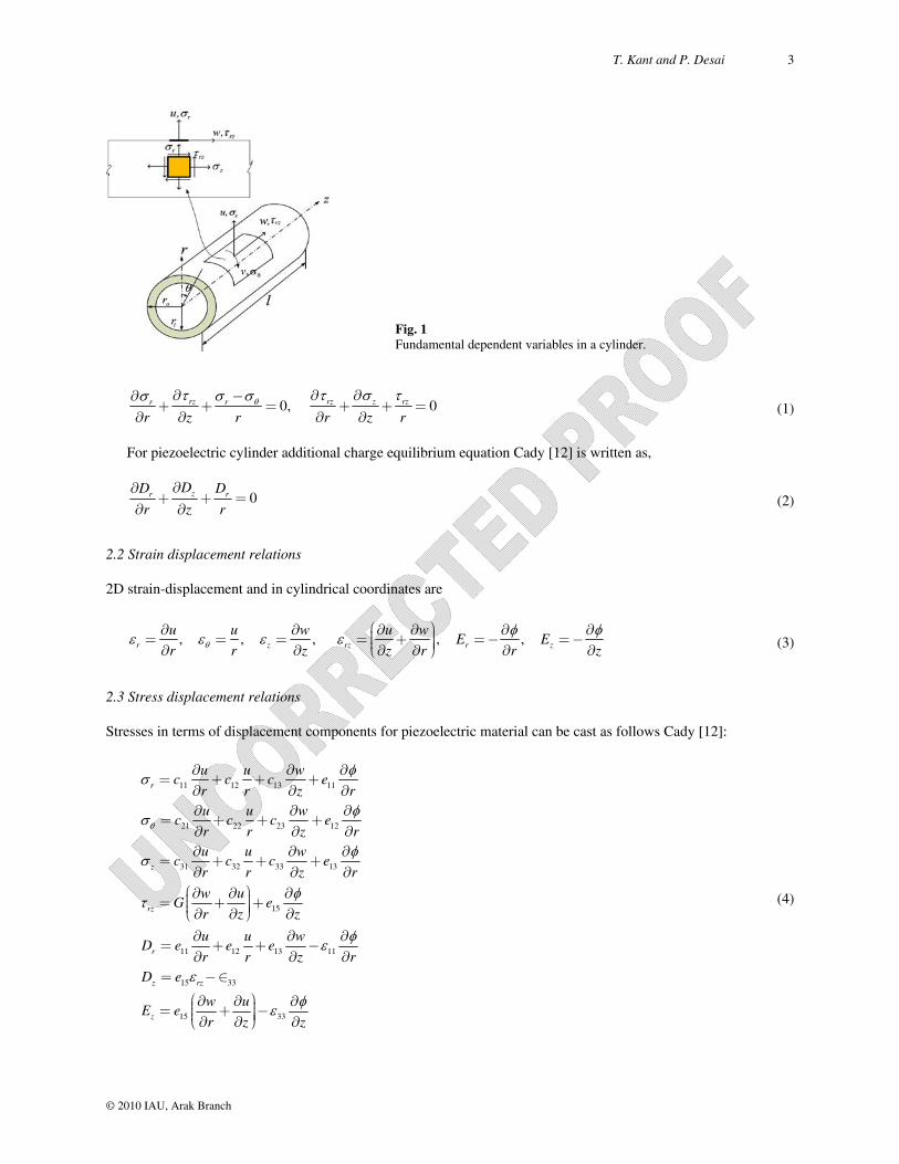
2D Stress equilibrium equation for finite length cylinder can be written as Timoshenko and Goodier [4], Fig. 1.
T. Kant and P. Desai 3
© 2010 IAU, Arak Branch
Fig. 1 Fundamental dependent variables in a cylinder.
0, 0rz rz z rzrr
r z r r z r ¶ ¶ ¶-¶
+ + = + + =¶ ¶ ¶ ¶
(1)
For piezoelectric cylinder additional charge equilibrium equation Cady [12] is written as,
0zr rDD D
r z r
¶¶+ + =
¶ ¶ (2)
2.2 Strain displacement relations
2D strain-displacement and in cylindrical coordinates are
, , , , , r z rz r z
u u w u wE E
r r z z r r z
æ ö¶ ¶ ¶ ¶ ¶ ¶÷ç= = = = + =- =-÷ç ÷÷çè ø¶ ¶ ¶ ¶ ¶ ¶ (3)
2.3 Stress displacement relations
Stresses in terms of displacement components for piezoelectric material can be cast as follows Cady [12]:
r
z
rz
r
z rz
z
u u wc c c e
r r z ru u w
c c c er r z ru u w
c c c er r z r
w uG e
r z z
u u wD e e e
r r z rD e
w uE e
r z
11 12 13 11
21 22 23 12
31 32 33 13
15
11 12 13 11
15 33
15
¶ ¶ ¶= + + +
¶ ¶ ¶¶ ¶ ¶
= + + +¶ ¶ ¶¶ ¶ ¶
= + + +¶ ¶ ¶
æ ö¶ ¶ ¶÷ç= + +÷ç ÷÷çè ø¶ ¶ ¶¶ ¶ ¶
= + + -¶ ¶ ¶
= -Î
æ ö¶ ¶ ÷ç= + ÷ç ÷÷çè ø¶ ¶z33
¶-
¶
(4)

4 Two-dimensional Axisymmetric Electromechanical Response …
© 2010 IAU, Arak Branch
where u is the radial displacement and φ is the electric potential, w is the axial displacement, Dr, Dz is the electric displacements. The elastic constants are c11, c12, c22, c23, c31, c33. The piezoelectric constant are e11, e12, e13, e15 and 11, 33 are the dielectric permittivities at constant strain, G is the shear modulus.
2.4 Boundary conditions
Boundary conditions in the longitudinal and radial directions are:
at 0, : 0, 0, 0
at : - , , 0
at : 0
z z
i r rz
o r rz
z l u D
r r p q
r r
= = = =
= = = =
= = = =
(5)
In which l is the length, ri is the inner radius and ro is the outer radius of a hollow cylinder. Load p(z) can be
represented in terms of Fourier series in general form as follows,
1,3,5..
( ) sinm
N
m
m zp z p
l
=
= å (6)
In which pi is the Fourier load coefficient which can be determined by using the orthogonality conditions and for
sinusoidal loading,
0( ) sinz
p z pl
=
where p0 is the maximum intensity of sinusoidal distributed pressure.
3 FIRST ORDER PARTIAL DIFFERENTIAL EQUATIONS
Radial direction r is chosen to be a preferred independent coordinate. Six fundamental dependent variables, viz., displacements, u, w and φ and corresponding stresses, σr, τrz and Dr that occur naturally on a tangent plane rconstant, are chosen in the radial direction. Circumferential stress σθ, axial stress σz and axial electric displacement Dz are treated here as auxiliary variables since these are found to be dependent on the chosen fundamental variables Kant and Ramesh [13]. A set of six first order partial differential equations in independent coordinate r which involve only fundamental variables is obtained through algebraic manipulation of Eqs. (1)-(4). These are,
11 12 14 16
21 23 25
31 32 34 36
41 42 44 45 46
51 52 54 55 56
61 63 65 66
0 0
0 0 0
0 0
0
0
0 0
r r
rz rz
r r
A A A Au u
A A Aw w
A A A A
A A A A Ar
A A A A A
A A A AD D
æ öæ ö æ÷÷ çç ÷÷ çç ÷÷ çç ÷÷ çç ÷÷ çç ÷÷ çç ÷÷ ÷÷ çç¶ ÷÷ çç ÷÷ çç = ÷÷ çç ÷÷ çç¶ ÷÷ çç ÷÷ çç ÷÷ çç ÷÷ ÷÷ çç ÷÷ çç ÷÷ çç ÷÷ çç ÷ ÷ç çè ø èè ø
ö÷ç ÷ç ÷ç ÷ç ÷ç ÷ç ÷÷ç ÷ç ÷ç ÷ç ÷ç ÷ç ÷ç ÷ç ÷÷ç ÷ç ÷ç ÷ç ÷ç ø
(7)
The A matrix coefficients are defined in Appendix A.

T. Kant and P. Desai 5
© 2010 IAU, Arak Branch
3.1 Basic fundamental variables
Variations of the six fundamental dependent variables which completely satisfy the boundary conditions of simple (diaphragm) supports at z0, l can then be assumed as,
1,3,5,... 1,3,5,... 1,3,5,...
1,3,5,... 1,3,5,... 1,3,5,...
( , ) ( ) sin , ( , ) ( ) cos , ( , ) ( ) sin
( , ) ( ) sin , ( , ) ( ) cos , ( , ) ( ) sin
N N N
i i r ii i i
N N N
r i rz i r ii i i
i z i z i zu r z U r w r z W r r z r
l l l
i z i z ir z r r z r D r z D r
l l
= = =
= = =
= = =
= = =
å å å
å å å z
l
(8)
4 FIRST ORDER ORDINARY DIFFERENTIAL EQUATIONS
Substitution of fundamental variables given in Eq. (8) into Eq. (7) and simplification resulting from orthogonality conditions of trigonometric functions leads to the following simultaneous first order ordinary differential equations (ODEs) involving only mixed fundamental variables.
11 12 14 16
21 23 25
31 32 34 36
41 42 44 45 46
51 52 54 55 56
61 63 65 66
0 0( )
0 0 0( )
0 0( )d0( )d
0( )
0 0( )
B B B BU r
B B BW r
B B B Br
B B B B Brr
B B B B Br
B B B BD r
æ öæ ö ÷÷ çç ÷÷ çç ÷÷ çç ÷÷ çç ÷÷ çç ÷÷ çç ÷÷ ÷ç÷ç ÷÷ çç ÷÷ çç = ÷÷ çç ÷÷ çç ÷÷ çç ÷÷ çç ÷÷ ç ÷ç ÷ ÷ç÷ç ÷÷ çç ÷÷ çç ÷÷ çç ÷ çè ø è ø
( )
( )
( )
( )
( )
( )
U r
W r
r
r
r
D r
æ ö÷ç ÷ç ÷ç ÷ç ÷ç ÷ç ÷÷ç ÷ç ÷ç ÷ç ÷ç ÷ç ÷ç ÷ç ÷÷ç ÷ç ÷ç ÷ç ÷÷è ø
(9)
The B matrix coefficients are defined in Appendix B. It is considered that all material constants have a power-
law dependence on the radial coordinate in case of FG cylinder, i.e., ( ) ( / )o niE r E r r= , nnon dimensional arbitrary
constant/ nonhomogeneity parameter, Eoconstant parameter which has the same dimension as E(r), riinner radius. E(r) is function dependent on position. Spatial variation of Poisson’s ratio is of much less practical significance than Young’s modulus. Hence, Poisson’s ratio is assumed to be constant. This assumption, commonly made in the literature on FG materials, leads to considerable mathematical simplification. It can be easily proved that when the material is isotropic and if n0 for the homogeneous case, results are same as given by Timoshenko and Goodier [4] for plane strain elasticity solution for Lame cylinder.
5 NUMERICAL INTEGRATION
The above system of first order simultaneous ordinary differential Eqs. (9) together with the appropriate boundary conditions at the inner and outer edges of the cylinder Eq. (5) forms a two-point BVP. However, a BVP in ODEs cannot be numerically integrated as only a half of the dependent variables (three) are known at the initial edge and numerical integration of an ODE is intrinsically an IVP. It becomes necessary to transform the problem into a set of IVPs. The initial values of the remaining three fundamental variables must be selected so that the complete solution satisfies the three specified conditions at the terminal boundary Kant and Ramesh [13]. The nth (n6 here) order BVP is transformed into a set of (n/2+1) IVPs. ODEs are integrated from initial edge to final edge using the initial values as shown in Table 1. The n/2+1 solutions given in the Table 1 may be thought of as (i) one non-homogeneous integration which includes all the non-homogeneous terms (e.g., loading) and the known n/2 quantities at starting edge, with the unknown n/2 quantities at the starting edge set as zero, (ii) n/2 homogeneous integrations which are carried out by setting the known quantities at the starting edge as zero and choosing the n/2 unknown quantities at starting edge as unit values in succession and deleting the non-homogeneous terms from the ODEs. The solutions at the terminal boundary corresponding to the initial values of Table 1 are given in the right Table 1

6 Two-dimensional Axisymmetric Electromechanical Response …
© 2010 IAU, Arak Branch
Table 1 Conversion of BVP into IVPs Integration number
Initial boundary Terminal boundary Load term
u w r rz Dr u w
r rz Dr
0 0 0 (Sp*) (Sp*) (Sp*) 0 Y1,0 Y2,0 Y3,0 Y4,0 Y5,0 Y6,0 In†
1 1 0 0 0 0 0 Y1,1 Y2,1 Y3,1 Y4,1 Y5,1 Y6,1 De‡
2 0 1 0 0 0 0 Y1,2 Y2,2 Y3,2 Y4,2 Y5,2 Y6,2 De‡ 3 0 0 0 0 0 1 Y1,3 Y2,3 Y3,3 Y4,3 Y5,3 Y6,3 De‡ Final integration
X1 X2 (Sp*) (Sp*) (Sp*) X3 Correct value
Correct value
Known Known Known Correct value
In†
*Sp: specified †In: include ‡De: delete side columns in Table 1. A linear combination of the (n/2+1) solutions must satisfy the boundary conditions at the terminal edge, i.e.,
33,0 3,1 3,2 3,3 11
4,0 4,1 4,2 4,3 2 ,0 , , ,04
5,1 5,2 5,3 35,0 5
or or ( ) i i j j i j i j i i
YY Y Y Y X
Y Y Y Y X Y Y X Y X Y Y YY
Y Y Y XY Y
-
ì üï ïì ü æ ö æ öï ï ï ï÷ ÷çï ï ç ï ï÷ ÷çï ï ç÷ ï ï÷ï ï ï ïç ç é ù÷ ÷+ = + = = -çí ý í ýç÷ ÷ ê úë ûç ç÷ ÷ï ï ï ïç ÷ ç ÷ï ï ï ï÷ç ÷ç÷çï ï ï ïè øè øï ï ï ïî þ ï ïî þ
(10)
where i indicate the n/2 variables consistent with the specified boundary values at terminal edge, j refers to solution
number and ranges from 1 to n/2, iY is a vector of specified dependent variables at the terminal boundary and jX is
a vector of unknown dependent variables at the starting edge. Finally a non-homogeneous integration with all the dependent variables known at the starting edge is carried out to get the desired results. Fourth order Runge-Kutta algorithm is used for the numerical integration of the IVPs. Stability of the present numerical technique is checked via convergence study by taking different step sizes in RK4 algorithm. The solution technique, fourth order Runge-Kutta-Gill routine, adopted here has an advantage of being self starting. The step size for the independent variable ’r’ can be varied without any difficulty. Because of this laminated and gradient material cylinders can be easily tackled with this technique. Computer program has been developed to handle the static response of finite length simply (diaphragm) supported (SS) orthotropic, cross-ply laminate, functionally graded and piezoelectric cylinders. All the computations are carried out using GNU fortran compiler on Linux machine. A flow chart Fig. 2 is given for the complete numerical procedure.
6 NUMERICAL EXAMPLES
Three sets of numerical results are presented for clear comparison, i.e., (1) results from the present 2D finite length cylinder formulation, (2) computations on the analytical formulae available for infinitely long cylinder under plane strain condition given in literature and (3) results of the 1D infinitely long cylinder which are numerically integrated by the present technique.
Example 1: Finite piezoelectric cylinder under sinusoidal pressure and electric load
Following cases are studied which cover the actuators and sensory response of the smart cylinder.

T. Kant and P. Desai 7
© 2010 IAU, Arak Branch
Fig. 2 Flowchart of numerical integration.

8 Two-dimensional Axisymmetric Electromechanical Response …
© 2010 IAU, Arak Branch
011 11
011 11
011 11
Case 1: ( ) 1, ( ) 0, ( ) 0, ( ) 0
Case 2: ( ) 0, ( ) 0, ( ) 1, ( ) 0
Case 3: ( ) 1, ( ) 0, ( ) 1, ( ) 0
r ri i o i
r ri o i
r ri i o i
r r p r r r r r rC C
r r r r r r r rC C
r r p r r r r r rC C
= =- = = = = = = =
= = = = = = = =
= =- = = = = = = =
(11)
Following material properties are used for the material Piezoceramics PZT-4 Galic and Horgan [8], Kangming and Noor [14].
C11= 115 × 109, C12= 74.3 × 10⁹, C13= 74.3 × 10⁹, C21= 74.3 × 10⁹, C22= 139 × 109 C23= 77.8 × 10⁹, C31= 74.3 × 10⁹, C32= 77.8 × 10⁹, C33= 139 × 109, G = 25.6 × 10⁹
Above Elastic constants are in Pa.
e1115.08 (C/m2), e12-5.08 (C/m2), e13-5.20 (C/m2), e1512.72 (C/m2), 11 5.62 × 10⁻⁹(F/m)
Non dimensionalized parameters are defined as follows
11
11 11 12 11
, , , , , rzr rr r rz
i i i
e D u wD u w a
C C r e r r C
= = = = = = (12)
Here, the cylinder is subjected to sinusoidal mechanical and electric loads; the results within the limited central length zone only are compared with the plane strain one dimensional solutions. A hollow cylinder is analyzed by taking ri/ro1/2 and two l/R ratios, 4/3 and 100/3. Radial and hoop quantities are maximum at zl/2 whereas axial quantities are maximum at z0, l. In Table 2, results are shown for Case 1 boundary conditions where only internal pressure is applied. Although the boundary condition includes zero electric potential at both inner and outer surfaces, an electric potential developed in the interior of the cross-section. Problem with purely electrical boundary condition as given in Case 2 is analysed next. In case 3, both electrical and mechanical boundary conditions are applied. Results for infinitely long piezoelectric cylinder from the present formulation is also given. Results are compared for all the three cases of boundary conditions for a cylinder with l/R100/3 with that of Galic and Horgan [9], which is infinitely long plane strain cylinder. Excellent agreement is seen. Fig. 3 shows distribution of electric potential and radial stress through thickness for ro/ri 2 for piezoelectric cylinder for Case 3 boundary conditions. Fig. 4 shows the distribution of radial electric displacement and shear stress through thickness for ro/ri 2 for piezoelectric cylinder for Case 3 boundary conditions. Comparison of the results is given in Table 2.
1 .0 1 .2 1 .4 1 .6 1 .8 2 .0
0 .0
0 .2
0 .4
0 .6
0 .8
1 .0
c a s e -3
r
P re s e n t in f in ite c y l in d e r P re s e n t f in i te c y l in d e r l /R = 4 /3 P re s e n t f in i te c y l in d e r l /R = 1 0 0 /3 G a l ic a n d H o rg a n
(a)
1 .0 1 .2 1 .4 1 .6 1 .8 2 .0
- 1 .0
- 0 .8
- 0 .6
- 0 .4
- 0 .2
0 .0 c a s e - 3
r
P r e s e n t in f in i te c y l in d e r P r e s e n t f in i te c y l in d e r l /R = 4 /3 P r e s e n t f in i te c y l in d e r l /R = 1 0 0 /3 G a l ic a n d H o r g a n
(b)
Fig. 3 Distribution of electric potential and radial stress through thickness for ro/ri=2 for piezoelectric cylinder.

T. Kant and P. Desai 9
© 2010 IAU, Arak Branch
1 .0 1 .2 1 .4 1 .6 1 .8 2 .0
-3 0
-2 5
-2 0
-1 5
-1 0
-5
c a s e -3
Drz
r
P re s e n t f in ite c y lin d e r l/R = 4 /3 P re s e n t f in ite c y lin d e r l/R = 1 0 0 /3
(a)
1 .0 1 .2 1 .4 1 .6 1 .8 2 .0
0 .0 0
0 .0 5
0 .1 0
0 .1 5
0 .2 0
0 .2 5
0 .3 0
c a s e -3
rz
r
P re s e n t f in ite c y lin d e r l /R = 4 /3 P re s e n t f in ite c y lin d e r l /R = 1 0 0 /3
(b)
Fig. 4 Distribution of radial electric displacement and shear stress through thickness for ro/ri=2 for piezoelectric cylinder.
Table 2 Electric potential (z = l/2) through thickness in non dimensional form for piezoelectric finite length cylinder for ro/ri=2
Present (1D) Present (2D) l/R=4/3 Present (2D) l/R=100/3 Analytical (1D) (Galic and Horgan [9])
r/ri (z = l/2) r/ri (z = l/2)
Case – 1 1 0 0.0000 0.0000 0.997528 -8.8E-14 1.2 -0.0416 -0.0276 -0.0430 1.197179 -0.04127 1.4 -0.051 -0.0342 -0.0530 1.39122 -0.05159 1.6 -0.0427 -0.0284 -0.0446 1.56967 -0.04444 1.8 -0.0243 -0.0155 -0.0255 1.806544 -0.02222 2 0 0.0000 0.0000 1.992399 -8.2E-08 Case – 2 1 0.9992 0.9992 0.9992 0.987228 0.999231 1.2 0.7679 0.6888 0.7593 1.20751 0.734819 1.4 0.552 0.4542 0.5402 1.383781 0.511529 1.6 0.3526 0.2721 0.3418 1.595061 0.306303 1.8 0.1691 0.1251 0.1624 1.806263 0.120676 2 0 0.0000 0.0000 1.973302 0.015373 Case -3 1 0.9992 0.9992 0.9992 1.005032 1 1.2 0.7263 0.6613 0.7163 1.210184 0.726829 1.4 0.501 0.4199 0.4872 1.409151 0.497561 1.6 0.3099 0.2437 0.2972 1.610227 0.307317 1.8 0.1448 0.1095 0.1370 1.81547 0.136585 2 0 0.0000 0.0000 1.99793 0.009756 (Cases 1, 2, 3)
Example 2: FG cylinder under external pressure loading
In the following, material properties and loading conditions are used for the analysis Horgan and Chan [7].
8 2 20, 2 10 KN/m , 1000 KN/mo oE p = = ´ = (13)
Non-dimesnional parameters are chosen as follows under pressure loading
r r
1, ( , ) ( , ), ( , , , ) ( , , , )z rz z rz
o o o
r Er u w u w
r p r p = = = (14)

10 Two-dimensional Axisymmetric Electromechanical Response …
© 2010 IAU, Arak Branch
Figs. 5 and 6 show the variation of radial and hoop stresses for ri/ro1/10 and inhomogeneity parameters n1/20, 1/2, 1/5 and 0 under pressure loading for l/ri1000 and l/ri5. Radial and hoop stresses are compared with analytical solutions given in Horgan and Chan [7] for infinitely long cylinder in Table 3. As seen from Figs 5 and 6, for l/ri1000, the value of radial stress decreases for higher value of inhomogeneity parameters. Thus, by selecting a proper value of n, it is possible to tailor the stresses as per the design requirements by engineers. Radial and hoop quantities are maximum at zl/2 whereas axial quantities are maximum at z0, l.
(a)
(b)
Fig. 5 Radial and hoop stress through thickness with different non-homogeneity parameters for ri/ro=1/10 and for l/ri=1000 under pressure loading.
(a)
(b)
Fig. 6 Radial and hoop stresses through thickness with different non-homogeneity parameters for ri/ro=1/10 for l/ri=5 under pressure loading. Table 3
Comparison of non-dimensional radial stress r (z=l/2) and hoop stress (z=l/2) through thickness for diaphragm supported
elastic cylinder under pressure loading for ri/ro = 1/10 and n = 1/5 Present - ( / 2)r z l = Horgan and Chan [7] Present - ( / 2)z l = Horgan and Chan [7]
r l/ri =5 l/ri=20 l/ri =1000 l/ri =5 l/ri =20 l/ri =1000
0.1 0.0000 0.000 0.000 0.0000 0.082 1.4449 1.583 1.5939
0.28 0.0731 0.7120 0.7705 0.7720 0.0636 0.9868 1.0788 1.0772
0.46 0.1771 0.8388 0.887 0.8875 0.0911 0.984 1.0685 1.0677
0.64 0.3876 0.9143 0.9403 0.9405 0.1483 1.0104 1.0862 1.0857
0.82 0.7416 0.9697 0.9746 0.9746 0.2459 1.0408 1.1063 1.1059
1 1.0000 1.0000 1.0000 1.0000 0.3767 1.0692 1.1251 1.1248

T. Kant and P. Desai 11
© 2010 IAU, Arak Branch
Example 3: Orthotropic and laminated 0o/90o, 0o/core/0o cylinder under external sinusoidal pressure load
Non dimensionalized parameters are defined as follows for pressure loading.
r r
1, ( , ) ( , ), ( , , , ) ( , , , )r
z rz z rz
Err u w u w
R pR p (15)
Following material properties, Kollar and Springer [15] are taken for orthotropic (0o) for Graphite-epoxy material and layered (0o/90o) cylinders. Below elastic constants are in N/m2.
Layer -1 (fibers are oriented in circumferential direction 0o)
6 6 6 69.65 10 , 148 10 , 9.65 10 , 3.015 10 , 0.3, 0.6, 0.3r z zr r zr zE E E G Layer-2 (fibers are oriented in axial direction 90o)
6 6 6 69.65 10 , 9.65 10 , 148 10 , 4.55 10 , 0.6, 0.3, 0.0195r z zr r zr zE E E G
Table 4 Non-dimensional radial stress, radial displacement and hoop stress for simple diaphragm supported orthotropic, layered (0o/90o) and sandwich composite cylinder for h/R=1/5, 1/20, 1/50 at r=R. Quantity
h/R
Present Lekhnitskii [17] Infinitely long cylinder l/R
1 4 100-200
r (z=l/2) (Orthotropic)
1/5 0.5263 0.5320 0.5324 0.5371 0.5371 1/20 0.5141 0.5153 0.5153 0.5164 0.5153 1/50 0.5062 0.5067 0.5067 0.5071 0.5071
u (z=l/2)(Orthotropic)
1/5 0.3344 0.3435 0.3438 0.3405 0.3405 1/20 1.3227 1.3251 1.3251 1.3243 1.3251 1/50 3.2812 3.2822 3.2822 3.2819 3.2819
(z=l/2)(Orthotropic)
1/5 5.2797 5.4266 5.4306 5.3834 5.4306 1/20 20.4390 20.4767 20.4776 20.4655 20.4776 1/50 50.4753 50.4903 50.4906 50.4858 50.4906
r (z=l/2) –(0o/90o)
1/5 0.9248 0.9833 0.9828 0.9828 0.9801 1/20 0.9474 0.9515 0.9514 0.9514 0.9514 1/50 0.9439 0.9443 0.9443 0.9443 0.9443
u (z=l/2)–(0o/90o)
1/5 0.5773 0.6017 0.5991 0.5914 0.5991 1/20 2.4200 2.4163 2.4148 2.3978 2.4148 1/50 6.0823 6.0700 6.0687 6.0334 6.1062
(z=l/2)–(0o/90o)
1/5 1.0635 1.1785 1.1811 1.1811 1.1811
1/20 2.8932 2.9651 2.9685 2.9686 2.9685
1/50 6.5333 6.5957 6.5993 6.6000 6.5993
r (z=l/2) –sandwich
1/5 0.5482 0.5528 0.5531 0.5531 0.5531
1/20 0.5202 0.5213 0.5214 0.5214 0.5214
1/50 0.5087 0.5091 0.5092 0.5092 0.5094
u (z=l/2)– sandwich
1/5 1.0606 1.0870 1.0870 1.1340 1.0869
1/20 4.0574 4.0651 4.0651 4.1095 4.0651
1/50 10.0249 10.0278 10.0278 10.0710 10.0278
(z=l/2)– sandwich
1/5 0.0539 0.0562 0.0562 0.0562 0.0562
1/20 0.1738 0.1743 0.1743 0.1743 0.1743
1/50 0.4116 0.4119 0.4119 0.4119 0.4119

12 Two-dimensional Axisymmetric Electromechanical Response …
© 2010 IAU, Arak Branch
Following material properties, Pagano [16] are taken for the (0o/core/0o) sandwich cylinder: Face Material properties are:
6 6 6 66.894 10 , 172.36 10 , 6.894 10 , 1.378 10 , 0.25, 0.25, 0.25r z zr r zr zE E E G
Core Material properties are: 6 6 6 63.44 10 , 0.275 10 , 0.275 10 , 0.413 10 , 0.0199, 0.0199, 0.25r z zr r zr zE E E G
Radial and hoop quantities are maximum at zl/2, whereas axial quantities are maximum at z0, l. Analytical
solution for radial stress, hoop stress and radial displacement from exact theory of anisotropic elasticity for infinitely long plane strain cylinder is given in Lekhnitskii [17]. These are used to validate and check the present results wherever applicable. Comparisons of the results are given in Table 4. Here, first a long cylinder is subjected to a sinusoidal pressure load; the results within the limited central length zone only are compared with the plane strain 1D solution. A good agreement is obtained. It is clearly seen that for infinitely long cylinders with higher l/R ratios, the results are very close to the elasticity solution given by Lekhnitskii [17], for thick, moderately thick and thin
cases. Fig. 7 shows the distribution of radial stress r and radial displacement u through thickness subjected to
sinusoidal loading for orthotropic cylinder.
0 .9 0 0 . 9 5 1 . 0 0 1 .0 5 1 . 1 0
0 . 3 0
0 . 3 2
0 . 3 4
0 . 3 6
0 . 3 8
0 . 4 0
0 . 4 2
h / R = 1 / 5
Rad
ial d
ispl
acm
ent a
t z =
l/2
R a d ia l d i s t a n c e r /R
l /R = 1 l /R = 4 l /R = 2 0 0 L e k h n i t s k i i
(a)
0 . 9 9 0 0 . 9 9 5 1 . 0 0 0 1 . 0 0 5 1 . 0 1 03 . 2 7 6
3 . 2 7 8
3 . 2 8 0
3 . 2 8 2
3 . 2 8 4
3 . 2 8 6
3 . 2 8 8
3 . 2 9 0h / R = 1 / 5 0
Rad
ial d
ispl
acm
ent a
t z =
l/2
R a d ia l d i s t a n c e r / R
l / R = 1 l / R = 4 l / R = 2 0 0 L e k h n i t s k i i
(b)
Fig. 7
Distribution of radial stress r and radial displacement u through thickness subjected to sinusoidal loading for orthotropic
cylinder.
7 CONCLUSIONS
Elasticity theory is utilized here for BVPs of finite length composite, FG and piezoelectric cylinders. A simply (diaphragm) supported cylinder under axisymmetric mechanical and electric load is considered as a two-dimensional (2D) plane strain problem of piezoelasticity. Mathematical model is based on the exact theory of piezoelasticity without any kinematic and kinetic assumptions. Basic equations are cast in a form suitable for numerical integration in the radial direction. Numerical integration technique adopted here is found to be very effective and accurate. Stresses and displacements in axial and radial directions from mechanical and electrical loadings in cylinders having various l/R ratios are presented for future reference.
APPENDIX A
11 12 11 12 11 1211
11 11 11 11 11 11
1,
e c e c e eA a a
r c c c c
13 11 13 1311 11
1211 11 11 11 11 11
,c e e ce e
A a az c c c c

T. Kant and P. Desai 13
© 2010 IAU, Arak Branch
11 1114
11 11 11 11
21
25
13 131132
11 11 11
1,
,
1,
,
e e aA
c c c
Az
AG
e ceA a a
c z
1116
11 11
1523
12 12 1131
11 11 11
1134
11 11
,
,
1,
,
e aA
c
eA
G z
e c eA a a
r c
eA a
c
3611
1,A a
21 11 12 11 21 12 11 12 21 12 12 12 12 1141 222
11 11 11 11 11 11 11 11 11
21 11 11 13 21 13 21 11 13 11 13 12 12 1342 23
11 11 11 11 11 11 11 11 11
1
1
c e c e a c c e e ac e e a e c e aA c
c c c c cr
c e e ac c c c e e a e ac e e eA c a
r c c c c c z
21 21 11 11 12 1144
11 11 11 11 11 11
11 ,
c c e e a e e aA
r c c c c
45 ,Az
21 11 1246
11 11 11
1,
c e a e aA
r c
11 12 11 31 31 12 31 11 12 13 12 13 12 1151 32
11 11 11 11 11 11 11 11 11
231 11 11 13 31 11 13 31 13 13 11 13 13 13
52 33211 11 11 11 11 11 11 11 11
e c e ac c c c e e a e e e c eA c a a
z r c c c c c
c e e ac c e e a c c e e ac e eA c a
c c c c cz
31 11 1311 1153 31
11 11 11 11 11 11
,c e aee e a
A cz c c c c
54
1,A
r
31 11 1356
11 11 11
,c e a e
A ac z
2
61 152,A e
z
2 215 15
63 112 2,
e eA
G z z
1565 ,
eA
G z
66 ,rDA
r
11 11
11 11
1
1a
e e
c
(A.1)
APPENDIX B
11 12 11 12 11 1211
11 11 11 11 11 11
11 1114
11 11 11 11
21
1,
1,
,
e c e c e eB a a
r c c c c
e e aB
c c c
Bl
13 11 13 1311 1112
11 11 11 11 11 11
1116
11 11
1523
,
,
,
c e e ce eB a a
l c c c c
e aB
c
eB
G l

14 Two-dimensional Axisymmetric Electromechanical Response …
© 2010 IAU, Arak Branch
25
13 131132
11 11 11
1,
,
BG
e ceB a a
l c
12 12 1131
11 11 11
1134
11 11
1,
,
e c eB a a
r c
eB a
c
3611
1,B a
21 11 12 11 21 12 11 12 21 12 12 12 12 1141 222
11 11 11 11 11 11 11 11 11
21 11 11 13 21 13 21 11 13 11 13 12 12 1342 23
11 11 11 11 11 11 11 11 11
1
1
c e c e a c c e e ac e e a e c e aB c
c c c c cr
c e e ac c c c e e a e ac e e eB c a
l r c c c c c
21 21 11 11 12 1144
11 11 11 11 11 11
11 ,
c c e e a e e aB
r c c c c
45 ,Bl
21 11 1246
11 11 11
11 12 11 31 31 12 31 11 12 13 12 13 12 1151 32
11 11 11 11 11 11 11 11 11
2
31 11 11 13 31 11 13 31 13 152 33
11 11 11 11 11 11
1
1
c e a e aB
r c
e c e ac c c c e e a e e e c eB c a a
r l c c c c c
c e e ac c e e a c c eB c
l c c c c
3 11 13 13 13
11 11 11
e ac e ea
c
31 11 1311 1154 31
11 11 11 11 11 11
31 11 1356
11 11 11
2 2
15 1563 11
,
,
,
c e aee e aB c
l c c c c
c e a eB a
l c
e eB
G l l
55
2
61 15
1565
1,
,
,
Br
B el
eB
G l
66
1B
r (B.1)
REFERENCES
[1] Heyliger P. R., Pan E., 2004, Static fields in magnetoelectroelastic laminates, AIAA Journal 42 (7): 1435-1443. [2] Kapuria S., Sengupta S., Dumir P.C., 1997, Three-dimensional solution for a hybrid cylindrical shell under
axisymmetric thermoelectric load, Archive of Applied Mechanics 67: 320-330. [3] Heyliger P. R., 1997, A note on the static behaviour of simply supported laminated piezoelectric cylinders,
International Journal of Solids and Structures 34 (29): 3781-3794. [4] Timoshenko S., Goodier J., 1951, Theory of Elasticity, New York, McGraw- Hill. [5] Misovec A., Kempner J., 1970, Approximate elasticity solution for orthotropic cylinder under hydrostatic pressure and
band loads, ASME Journal of Applied Mechanics 37(1): 101–108. [6] Chandrashekhara K., Kumar B. S., 1993, Static analysis of a thick laminated circular cylindrical shell subjected to
axisymmetric load, Composite Structures 23: 1-9. [7] Horgan C., Chan A., 1999, The pressurized hollow cylinder or disk problem for functionally graded isotropic linearly
elastic materials, Journal of Elasticity 55: 43–59. [8] Galic D., Horgan C., 2002, Internally pressurized radially polarized piezoelectric cylinders, Journal of Elasticity 66:
257–272. [9] Galic D., Horgan C., 2003, The stress response of radially polarized rotating piezoelectric cylinders, ASME Journal of
Applied Mechanics 70: 426-435. [10] Kapuria S. S., Dumir P., 1997, Three-dimensional solution for a hybrid cylindrical shell under axisymmetric
thermoelectric load, Archive of Applied Mechanics 67: 320–330.

T. Kant and P. Desai 15
© 2010 IAU, Arak Branch
[11] Ye W G., Chen R., Cai J., 2001, A uniformly heated functionally graded cylindrical shell with transverse isotropy, Mechanics Research Communication 28(5): 535–542.
[12] Cady W. G., 1946, Piezoelectricity: an introduction to the theory and applications of electromechanical phenomena in crystals, New York: McGraw-Hill Book.
[13] Kant T., Ramesh C., 1981, Numerical integration of linear boundary value problems in solid mechanics by segmentation method, International Journal of Numerical Methods in Engineering 17: 1233-1256.
[14] Kangming X., Noor A. K., 1996, Three-dimensional analytical solutions for coupled thermoelectroelastic response of multilayered cylindrical shells, AIAA Journal 34(4): 802-812.
[15] Kollar L. P., Springer G. S., 2003, Mechanics of Composite Structures, first edition. New York: Cambridge University Press.
[16] Pagano N. J., 1969, Exact solutions for composite laminates in cylindrical bending, Journal of Composite Materials 3: 398-411.
[17] Lekhnitskii S., 1968, Anisotropic Plates, Gordon and Breach Science, New York.