two-channel digital oscilloscopes 50 mhz to 300 ... - farnell
TRANSCRIPT

R&S®HMO1002, R&S®HMO1202Two-channel digital oscilloscopes50 MHz to 300 MHz bandwidth
Test
& M
easu
rem
ent
Prod
uct B
roch
ure
| 02.
01

2 Rohde & Schwarz R&S®HMO1002, R&S®HMO1202
Bandwidth50 MHz, 70 MHz, 100 MHz, 200 MHz or 300 MHz
Sampling rate1 Gsample total, 500 Msample per channel or 2 Gsample total, 1 Gsample per channel
Memory depth1 Msample in total, 500 ksample per channel or 2 Msample in total, 1 Msample per channel
QuickViewKey results at the press of a button
FFTThe easy way to analyze the signal spectrumat a resolution of up to 128 ksample
Auto measurementWide variety of measurement functions
AcquireHigh acquisition rate to identify signal faults
ChannelsHigh vertical sensitivity down to 1 mV/div
Pattern generatorProprietary 4-bit patterns with up to 2 ksample length and 50 Mbit/s
MSOMixed signal functionality over eight digital inputs as standard
Digital voltmeterVoltmeter measurements using the oscilloscope
Function generatorCommon waveforms (sine, square, pulse, triangle, ramp) up to 50 kHz
Serial bus analysisHardware-based triggering and decoding: I2C, SPI, CAN or LIN optionally available
Rohde & Schwarz R&S®HMO1002, R&S®HMO1202 3
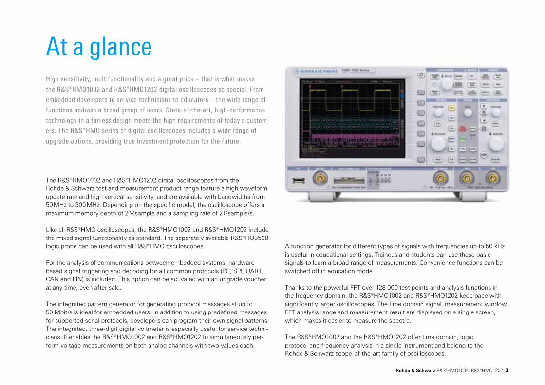
The R&S®HMO1002 and R&S®HMO1202 digital oscilloscopes from the Rohde & Schwarz test and measurement product range feature a high waveform update rate and high vertical sensitivity, and are available with bandwidths from 50 MHz to 300 MHz. Depending on the specific model, the oscilloscope offers a maximum memory depth of 2 Msample and a sampling rate of 2 Gsample/s.
Like all R&S®HMO oscilloscopes, the R&S®HMO1002 and R&S®HMO1202 include the mixed signal functionality as standard. The separately available R&S®HO3508 logic probe can be used with all R&S®HMO oscilloscopes.
For the analysis of communications between embedded systems, hardware-based signal triggering and decoding for all common protocols (I2C, SPI, UART, CAN and LIN) is included. This option can be activated with an upgrade voucher at any time, even after sale.
The integrated pattern generator for generating protocol messages at up to 50 Mbit/s is ideal for embedded users. In addition to using predefined messages for supported serial protocols, developers can program their own signal patterns. The integrated, three-digit digital voltmeter is especially useful for service techni-cians. It enables the R&S®HMO1002 and R&S®HMO1202 to simultaneously per-form voltage measurements on both analog channels with two values each.
A function generator for different types of signals with frequencies up to 50 kHz is useful in educational settings. Trainees and students can use these basic signals to learn a broad range of measurements. Convenience functions can be switched off in education mode.
Thanks to the powerful FFT over 128 000 test points and analysis functions in the frequency domain, the R&S®HMO1002 and R&S®HMO1202 keep pace with significantly larger oscilloscopes. The time domain signal, measurement window, FFT analysis range and measurement result are displayed on a single screen, which makes it easier to measure the spectra.
The R&S®HMO1002 and the R&S®HMO1202 offer time domain, logic, protocol and frequency analysis in a single instrument and belong to the Rohde & Schwarz scope-of-the-art family of oscilloscopes.
High sensitivity, multifunctionality and a great price – that is what makes
the R&S®HMO1002 and R&S®HMO1202 digital oscilloscopes so special. From
embedded developers to service technicians to educators – the wide range of
functions address a broad group of users. State-of-the-art, high-performance
technology in a fanless design meets the high requirements of today's custom-
ers. The R&S®HMO series of digital oscilloscopes includes a wide range of
upgrade options, providing true investment protection for the future.
At a glance
4 Rohde & Schwarz R&S®HMO1002, R&S®HMO1202
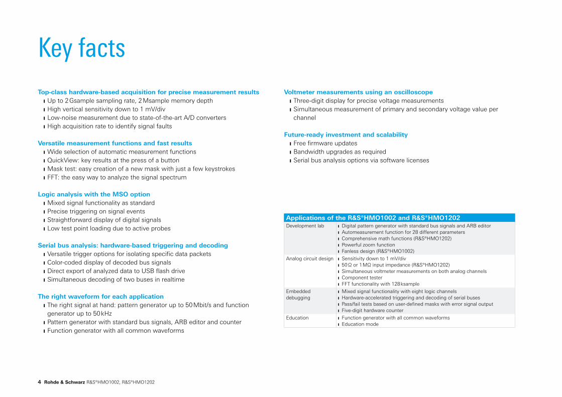
Key factsTop-class hardware-based acquisition for precise measurement results
Up to 2 Gsample sampling rate, 2 Msample memory depth High vertical sensitivity down to 1 mV/div Low-noise measurement due to state-of-the-art A/D converters High acquisition rate to identify signal faults
Versatile measurement functions and fast results Wide selection of automatic measurement functions QuickView: key results at the press of a button Mask test: easy creation of a new mask with just a few keystrokes FFT: the easy way to analyze the signal spectrum
Logic analysis with the MSO option Mixed signal functionality as standard Precise triggering on signal events Straightforward display of digital signals Low test point loading due to active probes
Serial bus analysis: hardware-based triggering and decoding Versatile trigger options for isolating specific data packets Color-coded display of decoded bus signals Direct export of analyzed data to USB flash drive Simultaneous decoding of two buses in realtime
The right waveform for each application The right signal at hand: pattern generator up to 50 Mbit/s and function generator up to 50 kHz
Pattern generator with standard bus signals, ARB editor and counter Function generator with all common waveforms
Applications of the R&S®HMO1002 and R&S®HMO1202Development lab Digital pattern generator with standard bus signals and ARB editor
Automeasurement function for 28 different parameters Comprehensive math functions (R&S®HMO1202) Powerful zoom function Fanless design (R&S®HMO1002)
Analog circuit design Sensitivity down to 1 mV/div 50 Ω or 1 MΩ input impedance (R&S®HMO1202) Simultaneous voltmeter measurements on both analog channels Component tester FFT functionality with 128 ksample
Embedded debugging
Mixed signal functionality with eight logic channels Hardware-accelerated triggering and decoding of serial buses Pass/fail tests based on user-defined masks with error signal output Five-digit hardware counter
Education Function generator with all common waveforms Education mode
Voltmeter measurements using an oscilloscope Three-digit display for precise voltage measurements Simultaneous measurement of primary and secondary voltage value per channel
Future-ready investment and scalability Free firmware updates Bandwidth upgrades as required Serial bus analysis options via software licenses
HV572R&S®HMO1002
R&S®HMO1202
HV512
HV313
HV712
HV312 HV323
100MHz
100MHz 200MHz 300MHz
70MHz50MHz
Rohde & Schwarz R&S®HMO1002, R&S®HMO1202 5
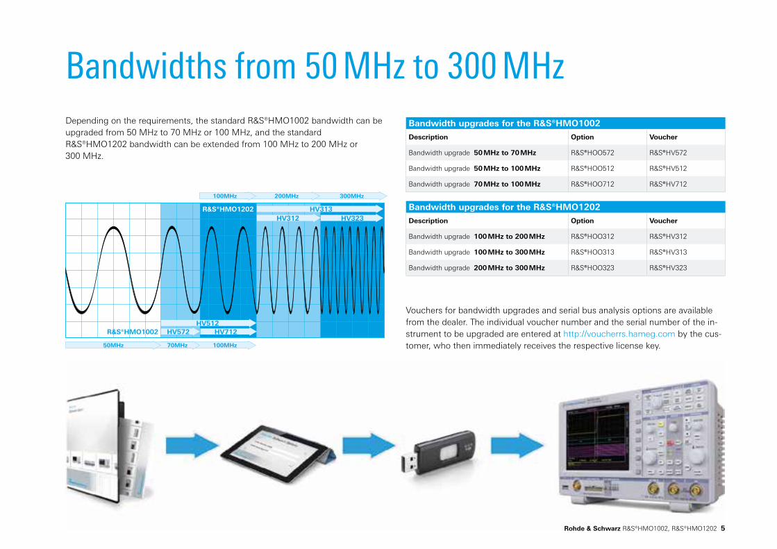
Bandwidths from 50 MHz to 300 MHzDepending on the requirements, the standard R&S®HMO1002 bandwidth can be upgraded from 50 MHz to 70 MHz or 100 MHz, and the standard R&S®HMO1202 bandwidth can be extended from 100 MHz to 200 MHz or 300 MHz.
Bandwidth upgrades for the R&S®HMO1002
Description Option Voucher
Bandwidth upgrade 50 MHz to 70 MHz R&S®HOO572 R&S®HV572
Bandwidth upgrade 50 MHz to 100 MHz R&S®HOO512 R&S®HV512
Bandwidth upgrade 70 MHz to 100 MHz R&S®HOO712 R&S®HV712
Bandwidth upgrades for the R&S®HMO1202
Description Option Voucher
Bandwidth upgrade 100 MHz to 200 MHz R&S®HOO312 R&S®HV312
Bandwidth upgrade 100 MHz to 300 MHz R&S®HOO313 R&S®HV313
Bandwidth upgrade 200 MHz to 300 MHz R&S®HOO323 R&S®HV323
Vouchers for bandwidth upgrades and serial bus analysis options are available from the dealer. The individual voucher number and the serial number of the in-strument to be upgraded are entered at http://voucherrs.hameg.com by the cus-tomer, who then immediately receives the respective license key.

6 Rohde & Schwarz R&S®HMO1002, R&S®HMO1202
Although it is unusual for this instrument class, the standard R&S®HMO1002 and R&S®HMO1202 oscilloscopes feature mixed signal functionality with no software option necessary to unlock it. Analog and digital signals can be simultaneously measured and analyzed.
New for the R&S®HMO1202: no loss of the second analog channel during measurements in MSO mode. Two analog and eight digital channels are always available.
A typical real-life example is the integration of analog-to-digital converters (ADC) or digital-to-analog converters (DAC). In this case, the mixed signal technology enables users to determine latency periods using a simple cursor measurement. An MSO allows developers to fully focus on the circuit instead of on the test setup.
The R&S®HO3508 active logic probe is available separately and is not linked to a specific instrument. It can be used with all R&S®HMO oscilloscopes.
Always an MSO Optional: R&S®HO3508 logic probe
The R&S®HO3508 logic probe fits all R&S®HMO series oscilloscopes
No hardware lock to a specific oscilloscope Eight logic channels available on each logic probe Signal threshold adjustment for each logic probe
SpecificationsChannels 8
Input impedance 100 kΩ || <4 pF
Max. input frequency 350 MHz
Max. input voltage 40 V (DC + AC)
Signal threshold TTL, CMOS, ECL, user-defined (–2 V to +8 V)
Measurement category CAT I
Cable length approx. 1 m
Eight-bit DAC signal change.

Rohde & Schwarz R&S®HMO1002, R&S®HMO1202 7
Serial bus analysisI2C, SPI, CAN or LIN are without a doubt the most frequently used communications protocols when it comes to embedded systems interacting with the outside world. The R&S®HMO1002 and R&S®HMO1202 oscilloscopes offer hardware-based signal triggering and decoding for all of these protocols. Customers can upgrade their instruments via software license keys with the functions they need to develop their application:
Serial bus trigger types: I2C: start, stop, ACK, NACK, address, data
SPI: start, end, serial pattern (32 bit) UART/RS-232: start bit, frame start, symbol, pattern
LIN: frame start, wake up, identifier, data, error
CAN: frame start, frame end, data, identifier, error
I2C bus signal in zoom view. HEX decoded CAN bus signal. SPI bus signal, MISO / MOSI decoded.
Bus analysis options
Description Option Voucher
I2C, SPI, UART/RS-232 on analog and logic channels
R&S®HOO10 R&S®HV110
I2C, SPI, UART/RS-232 on all analog channels R&S®HOO11 R&S®HV111
CAN and LIN on analog and logic channels R&S®HOO12 R&S®HV112

8 Rohde & Schwarz R&S®HMO1002, R&S®HMO1202
Functions for everyday usePattern generator
Are you working in a distributed project, and the interface definition has been completed but the prototype hardware has yet to be implemented? The pattern generator includes a tool for user-programmable 4-bit bus signals that allows you, for example, to emulate a sensor signal in order to continue your work.
Generate protocol messages at speeds of up to 50 Mbit/s
Use predefined signal patterns: I2C, SPI, UART, CAN, LIN
Create your own patterns tailored to your needs, or modify the predefined signal patterns

Rohde & Schwarz R&S®HMO1002, R&S®HMO1202 9
Function generator
Select the signal type suitable for your scope of application. The various basic types with frequencies of up to 50 kHz not only assist trainees and students with their measurements, they also support audio technicians with their assessments of filters.
The function generator offers all common basic waveforms up to 50 kHz
Available waveforms: sine, square wave, pulse, triangle and ramp
Powerful, all-in-one instrument with education mode, which allows you to turn off automatic measuring functions for educational and demonstration purposes
Digital voltmeter (DVM)
The three-digit digital voltmeter is another standard feature that is particularly useful for service technicians. Voltage measurements can be performed simultaneously for both analog channels. Integrated into a single compact device, it helps you keep your workplace tidy.
Simultaneous measurements on both analog channels, with two user-definable parameters each
Available options: DC, AC + DCRMS, crest factor, Vpp, Vp+, Vp–
You determine the position of the values on the screen
Component tester
Our tried and tested component tester will also be at your side. A 50 Hz and a 200 Hz measuring frequency is provided to support your potentially tedious search for faulty components. And since a picture says more than a thousand words – or rather a thousand values – you will be able to tell at a glance if your error analysis is on track.
Vid
eo
R&S®HMO1002 product video
Scan, click or go directly to
http://youtube.com/HAMEGcom

10 Rohde & Schwarz R&S®HMO1002, R&S®HMO1202
Frequency analysisDue to the high-performance FFT functionality of the R&S®HMO oscilloscopes, signals can also be analyzed in the frequency domain with up to 128 000 points. Other practical tools include cursor measurements and detection of signal peaks. Development engineers can complete their analysis significantly faster, even in the frequency domain.
Easy analysis in the frequency domain
Quite often, the distortion of input signals cannot be detected with the naked eye in the time domain. For example, a sine-wave signal might appear undistorted at first glance. Only the frequency spectrum shown in the frequency domain clearly displays additional harmonics that occur at multiples of the fundamental frequency.
Since the FFT function can also be applied to stored waveforms, selected segments of signals acquired in single or stop mode can be analyzed later using a window with user-selectable width.
Sinusoidal signal in the time domain. The frequency spectrum reveals the signal distortion.

Rohde & Schwarz R&S®HMO1002, R&S®HMO1202 11
Comparison of R&S®HMO1002/1202 oscilloscopes
Options and Upgrades
R&S®HMO1002 R&S®HMO1202
Bandwidth 50 MHz, 70 MHz, 100 MHz(upgrade via software license)
100 MHz, 200 MHz, 300 MHz(upgrade via software license)
Analog channels 2x 1 MΩ 2x 1 MΩ or 2x 50 Ω
Sampling rate 2x 500 Msample/s or 1x 1 Gsample/s 2x 1 Gsample/s or 1x 2 Gsample/s
Memory depth 2x 500 ksample or 1x 1 Msample 2x 1 Msample or 1x 2 Msample
MSO modeswith R&S®HO3508 probe
CH1 + POD or CH1 + CH2 CH1 + CH2 + POD
Digital channels(sampling rate / memory depth)
8x 500 Msample/s at8x 500 ksample
8x 1 Gsample/s at8x 1 Msample
External trigger input external trigger only external trigger, auxiliary logic channel
Mathematics QuickMath complex math functions with formula editor
Cooling fanless low-noise, temperature-regulated fan control circuit
Bandwidth upgrades for the R&S®HMO1002
Description Option Voucher
Bandwidth upgrade 50 MHz to 70 MHz R&S®HOO572 R&S®HV572
Bandwidth upgrade 50 MHz to 100 MHz R&S®HOO512 R&S®HV512
Bandwidth upgrade 70 MHz to 100 MHz R&S®HOO712 R&S®HV712
Bandwidth upgrades for the R&S®HMO1202
Description Option Voucher
Bandwidth upgrade 100 MHz to 200 MHz R&S®HOO312 R&S®HV312
Bandwidth upgrade 100 MHz to 300 MHz R&S®HOO313 R&S®HV313
Bandwidth upgrade 200 MHz to 300 MHz R&S®HOO323 R&S®HV323
Bus analysis options for R&S®HMO oscilloscopes
Description Option Voucher
I2C, SPI, UART/RS-232 on analog and logic channels R&S®HOO10 R&S®HV110
I2C, SPI, UART/RS-232 on all analog channels R&S®HOO11 R&S®HV111
CAN and LIN on analog and logic channels R&S®HOO12 R&S®HV112
Formula editor view for complex math functions (R&S®HMO1202).
Service options
Extended Warranty, one year R&S®WE1 Please contact your local Rohde & Schwarz sales office.
Extended Warranty, two years R&S®WE2
Extended Warranty with Calibration Coverage, one year R&S®CW1
Extended Warranty with Calibration Coverage, two years R&S®CW2
12 Rohde & Schwarz R&S®HMO1002, R&S®HMO1202
R&S®HMO1202 series <5 mV/Div: 10 Hz to 130 MHz >5 mV/Div: 10 Hz to 130/220/300 MHz
DC
R&S®HMO1002 series <5 mV/Div: DC to 65 MHz >5 mV/Div: DC to 65/90/130 MHz
R&S®HMO1202 series <5 mV/Div: DC to 130 MHz >5 mV/Div: DC to 130/220/300 MHz
HF
R&S®HMO1002 series <5 mV/Div: 30 kHz to 65 MHz >5 mV/Div: 30 kHz to 65/90/130 MHz
R&S®HMO1202 series <5 mV/Div: 30 kHz to 130 MHz >5 mV/Div: 30 kHz to 130/220/300 MHz
selectable filters
LF DC to 5 kHz (-3 db), selectable in DC and auto level mode
noise rejection min. level: 1.5 Div (> 5 mV/Div) selectable with AC, DC and HF coupling
Trigger hold-off auto, 50 ns to 10 s
External Input (BNC)
Function ext. trigger input, additional digital channel
Impedance 1 MΩ || 16 pF ±2 pF
Acurracy 300 mVss
Trigger level range -5 V bis +5 V
Max. input voltage 100 Vs (derates at 20 db/decade to 5 V above 100 kHz)
Trigger coupling
AC
R&S®HMO1002 series R&S®HMO1202 series
10 Hz to 50/70/100 MHz 10 Hz to 100/200/300 MHz
DC
R&S®HMO1002 series R&S®HMO1202 series
DC to 50/70/100 MHz DC to 100/200/300 MHz
Trigger Output via AUX OUT (BNC)
Functions Pulse output for every acquisition trigger event, error output on mask violation
Output level approx. 3 V
Pulse polarity positive
Pulse width >150 ns (trigger event), >0.5 µs (mask violation)
Trigger Types
Edge
Direction rising, falling, both
Trigger coupling auto level AC, DC, HF
Switchable filters LF, noise rejection
Sources
R&S®HMO1002, R&S®HMO1202
all analog and digital channels, AC line, external (AC, DC)
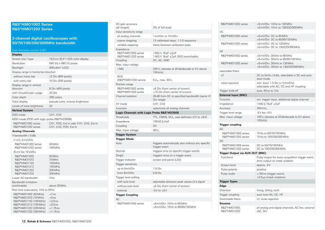
R&S®HMO1002 Series R&S®HMO1202 Series 2-channel digital oscilloscopes with 50/70/100/200/300MHz bandwidth from firmware version 5.457
Display
Screen size / type 16,5 cm (6,5“) VGA color display
Resolution 640 (H) x 480 (V) pixels
Backlight 400 cd/m2 (LED)
Display range in horizontal direction
without menu bar 12 Div (600 pixels)
with menu bar 10 Div (500 pixels)
Display range in vertical direction
8 Div (400 pixels)
with VirtualScreen usage 20 Div
Color depth 256 colors
Trace display pseudo-color, inverse brightness
Levels of trace brightness 32
Vertical System
DSO mode CH1, CH2
MSO mode (POD with logic probe R&S®HO3508)
R&S®HMO1002 series R&S®HMO1202 series
CH1, POD, Ext.In oder CH1, CH2, Ext.In CH1, CH2, POD, Ext.In
Analog Channels
Y-bandwidth (-3 dB)
(1 mV, 2 mV)/Div
R&S®HMO1002 series R&S®HMO1202 series
50 MHz 100 MHz
(5 mV bis 10 V)/Div
R&S®HMO1002 R&S®HMO1072 R&S®HMO1102 R&S®HMO1212 R&S®HMO1222 R&S®HMO1232
50 MHz 70 MHz 100 MHz 100 MHz 200 MHz 300 MHz
Lower AC bandwidth 2 Hz
Bandwidth limitation (switchable)
about 20 MHz
Rise time (calculated, 10% to 90%)
R&S®HMO1002 (50 MHz) R&S®HMO1072 (70 MHz) R&S®HMO1102 (100 MHz) R&S®HMO1212 (100 MHz) R&S®HMO1222 (200 MHz) R&S®HMO1232 (300 MHz)
<7 ns <5 ns <3.5 ns <3.5 ns <1.75 ns <1.15 ns
DC gain accuracy (all ranges)
3% of full scale
Input sensitivity range
all analog channels 1 mV/Div to 10 V/Div
coarse stepping 13 calibrated steps, 1-2-5 sequence
variable stepping freely between calibrated steps
Impedance R&S®HMO1002 series R&S®HMO1202 series
1 MΩ II 16 pF ±2 pF 1 MΩ II 16 pF ±2 pF, 50 Ω (switchable)
Coupling DC, AC, GND
Max. input voltage
1 MΩ 200 Vp (derates at 20 db/decade to 5 V above 100 kHz)
50 Ω (R&S®HMO1202 series)
5 Veff, max. 30 Vs
Position range
R&S®HMO1002 series R&S®HMO1202 series
±5 Div (from center of screen) ±15 Div (from center of screen)
Channel isolation 35 dB from DC to specified bandwidth (same V/Div range)
XY mode CH1, CH2
Inversion selectively all analog channels
Logic Channels with Logic Probe R&S®HO3508
Thresholds TTL, CMOS, ECL, user-definied (-2 V to +8 V)
Impedance 100 kΩ || 4 pF
Coupling DC
Max. input voltage 40 Vp
Trigger System
Trigger Mode
Auto triggers automatically also without any specific trigger event
Normal triggers only on specific trigger events
Single triggers once on a trigger event
Trigger indicator screen and panel (LED)
Trigger sensitivity
up to 5mV/Div 1.5 Div
from 5mV/Div 0.8 Div
Trigger level setting
with auto level adjustable between peak values of a signal
without auto level ±5 Div (from center of screen)
external -5 V to +5 V
Trigger Coupling
AC
R&S®HMO1002 series <5 mV/Div: 10 Hz to 65 MHz >5 mV/Div: 10 Hz to 65/90/130 MHz

Rohde & Schwarz R&S®HMO1002, R&S®HMO1202 13
Component tester voltage (X), current (Y)
Reference signals up to 4 references
Channel deskew ±32 ns, step size 2 ns
Memory zoom up to 50.000 : 1
Time base
accuracy ±50.0 x 10⁻⁶
aging ±10.0 x 10⁻⁶ per year
Operation modes
REFRESH
R&S®HMO1002 series R&S®HMO1202 series
2 ns/Div to 50 s/Div 1 ns/Div to 50 s/Div
ROLL 50 ms/Div to 50 s/Div
Acquisition System
Realtime Sampling Rate
Analog channels
R&S®HMO1002 series R&S®HMO1202 series
2x 500 MSa/s or 1x 1 GSa/s 2x 1 GSa/s or 1x 2 GSa/s
Logic channels
R&S®HMO1002 series R&S®HMO1202 series
8x 500 MSa/s 8x 1 GSa/s
Memory depth
Analog channels
R&S®HMO1002 series R&S®HMO1202 series
2x 500 kSa or 1x 1 MSa 2x 1 MSa or 1x 2 MSa
Logic channels
R&S®HMO1002 series R&S®HMO1202 series
500 kSa per channel 1 MSa per channel
Resolution 8 Bit, (HiRes up to 16Bit)Waveform arithmetics
refresh, roll (loose/triggered), average (up to 1024), envelope, peak detect (2 ns), filter (low-pass, adjustable), high resolution (up to 16 bit)
Record modes automatic, max. sampling rate, max. waveform rate
Interpolation
all analog channels sin(x)/x, linear, sample-hold
logic channels pulse
Delay
pre-trigger
R&S®HMO1002 series R&S®HMO1202 series
0 to 500.000 Sa x (1/sample rate) 0 to 1.000.000 Sa x (1/sample rate) (multiplied by 2 in interlaced mode)
post-trigger 0 to 8x106 Sa x (1/sample rate)
Waveform update rate up to 10,000 Wfm/s
Waveform display dots, vectors, persistence afterglow
Persistence afterglow min. 50 ms
Waveform Measurements and Operation
Operation menu-driven (multilingual), auto-set, help functions (multilingual)
Automatic measurements
voltage (Vpp, Vp+, Vp-, Vrms, Vavg, Vmin, Vmax), amplitude, phase, frequency, period, rise/fall time (80%, 90%), pulse width (pos/neg), burst width, duty cycle (pos/neg), standard deviation, delay, crest factor, overshoot (pos/neg), edge/pulse count (pos/neg), trigger period, trigger frequency
Cursor measurements
voltage (V1, V2, ∆V), time (t1, t2, ∆t, 1/∆t), ratio X, ratio Y, pulse and edge count (pos/neg), peak values (Vpp, Vp+, Vp-), Vmean, Vrms, standard deviation, duty cycle (pos/neg), rise/fall time (80%, 90%), ratio marker, crest factor
Quick measurements (QUICKVIEW)
voltage (Vpp, Vp+, Vp-, Vrms, Vmean), rise/fall time, frequency, period plus 6 additional measurement functions (see automatic measurement functions, freely selectable)
Marker up to 8 freely positionable markers for easy navigation
Frequency Counter (hardware based)
Resolution 5 digit
Frequency range
R&S®HMO1002 R&S®HMO1202
0.5 Hz bis 50/70/100 MHz 0.5 Hz bis 100/200/300 MHz
Accuracy ±50.0 x 10⁻⁶
Aging ±10.0 x 10⁻⁶ per year
Mask Testing
Functions Pass/Fail comparison with an user-definied mask performed on waveforms
Sources all analog channels
Mask definition Mask enclosing acquired waveform with user-defined tolerance
Actions
on mask violations beep, acquisition stop, screenshot, trigger pulse, automatically saving trace data
during acquisiton
statistics: number of completed tests, number of passes / failed acquisitions (absolute and in percent), test duration
Waveform Maths
Quickmath
Functions addition, substraction, multiplication, division
Sources CH1, CH2
Mathematics (R&S®HMO1202 series)
Functions
addition, substraction, multiplication, division, minimum / maximum, square, square root, absolute value, pos/neg wave, reciprocal, inverse, log10/ln, derivation, integration, filter (lowpass/highpass)
Pulse Width
Polarity positive, negative
Functions equal, not equal, lower, higher, within/without a range
Pulse duration 16ns to 10s, resolution min. 2ns
Sources all analog channels
Logic
Functions
boolean operators AND, OR, TRUE, FALSE
time based operators equal, not equal, lower, higher, within/without a time range, timeout
Duration 16 ns to 10 s, resolution min. 2 ns
States H, L, X
Sources all logic channels
Video
Sync. pulse polarity positive, negative
Supported standards NTSC, SECAM, PAL, PAL-M, SDTV 576i, HDTV 720p, HDTV 1080i, HDTV 1080p
Field even/odd, either
Line line number selectable, all
Sources all analog channels, external (AC, DC)
Serial Busses (optional) Bus representation
Up to two busses can be analyzed at the same time. Color-coded display of decoded data in ASCII, binary, decimal and hexadecimal format.
Option / Voucher codes
R&S®HOO10, R&S®HV110 Analysis of I2C, SPI, UART/RS-232 signals on analog and logic channels
R&S®HOO11, R&S®HV111 Analysis of I2C, SPI, UART/RS-232 signals on all analog channels
R&S®HOO12, R&S®HV112 Analysis of CAN and LIN signals on analog and logic channels
Trigger types by protocols
I2C Start, Stop, ACK, NACK, Address/Data
SPI Start, End, Serial Pattern (32 Bit)
UART/RS-232 Startbit, Frame Start, Symbol, Pattern
LIN Frame Start, Wake Up, Identifier, Data, Error
CAN Frame Start, Frame End, Identifier, Data, Error
Horizontal System
Time domain (Yt) main screen, time domain and zoom window
Frequency domain (FFT) time domain and frequency domain window (FFT)
XY mode voltage (XY)
VirtualScreen virtual display of ±10 Div for all math, logic, bus, reference signals

14 Rohde & Schwarz R&S®HMO1002, R&S®HMO1202
All specifications at 23°C after 30 minutes warm-up
Measured value (meas.): characterizes an expected product performance by means of measurement results gained from individual samples.
Accessories included: Line cord, printed operating manual, 2x RT-ZP03 probes, HZ20 adapter: BNC plug to 4 mm banana sockets, software-CD
Editing formula editor, menu-driven
Sources all analog channels, user-defined constants
Storage location math. memory
Number of formula sets 5 formula sets
Number of equations 5 equations per formula set
Simultaneous display of math. functions
1 formula set with max. 4 equations
Frequency Analysis (FFT)
Parameters frequency span, center frequency, vertical scale, vertical position
FFT length 2 Kpts, 4 Kpts, 8 Kpts, 16 Kpts, 32 Kpts, 64 Kpts, 128 Kpts
Window Hanning, Hamming, Rectangular, Blackman
Scale dBm, dBV, Vrms
Waveform arithmetics refresh, envelope, average (up to 512)
Cursor measurement 2 horizontal cursors, previous / next peak search
Sources all analog channels
Probe Adjust Output
Operation manual, adjust-wizzard
Frequence 1 kHz, 1 MHz
Level
R&S®HMO1002 series R&S®HMO1202 series
approx. 2.5 Vpp (ta <4 ns) approx. 2.5 Vpp (ta <1 ns)
Pattern Generator
Functions square wave / probe adjust, bus signal source, counter, programmable pattern
Square wave (Probe ADJ output)
frequency range: <1 mHz to 500 kHz level: 2.5 Vpp (ta <4 ns) polarity: normal, invert duty cycle: 1% to 99%
Bus Signal Source (4 Bit)
I2C (100 kBit/s, 400 kBit/s, 1 MBit/s), SPI (100 kBit/s, 250 kBit/s, 1 MBit/s), UART (9600 Bit/s, 115,2 kBit/s, 1 MBit/s), CAN (up to 50 MBits/s), LIN (up to 50 MBits/s)
Counter (4 Bit) frequency: <1 mHz to 25 MHz direction: incrementing, decrementing
Programmable pattern (4 Bit)
sampling time: 20 ns to 42 s memory depth: 2048 sa pattern idle time: 20 ns to 42 s
Function Generator
Waveform modes DC, sine, square, triangle/ramp, pulse
Sine
frequency range: 0.1 Hz to 50 kHz flatness: ±1 dB relative to 1 kHz DC offset: max. ±3 V
Square
frequency range: 0.1 Hz to 25 kHz rise time: <4 µs DC offset: max. ±3 V
Triangle / Ramp frequency range: 0,1 Hz bis 10 kHz DC offset: max. ±3 V
Pulse
frequency range: 0.1 Hz to 10 kHz duty cycle: 10% to 90% DC offset: max. ±3 V
Sampling rate 978 kSa/s
Frequency accuracy ±50.0 x 10⁻⁶
Aging ±10.0 x 10⁻⁶ per year
Amplitude
DC ±3 V
DC offset error (meas.) ±25 mV (max.)
high impedance load 60 mVpp to 6 Vpp
50 Ω load 30 mVpp to 3 Vpp
accuracy 3%
Digital Voltmeter
Display (3-digit)
Primary and secondary measurement value per channel, simultaneous measuring on all channels
Functions DC, DCrms, ACrms, Vpp, Vp+, Vp-, crest factor
Sources all analog channels
Component Tester
Parameters voltage (X), current (Y)
Testing frequency 50 Hz, 200 Hz
Voltage 10 Vp (open)
Current 10 mA (short)
Reference potential Ground (PE)
Interfaces
for mass storage (FAT16/32)
1x USB host (type A), max. 500 mA
for remote control Ethernet (RJ45), USB device (type B)
General Data
Application memory 3 MB for references and device settings
Save / Recall
device settings on internal file system or external USB memory, available file formats: SCP, HDS
reference waveforms
on internal file system or external USB memory, available file formats: BIN (MSB/LSB), FLT (MSB/LSB), CSV, TXT, HRT
traces
on external USB memory, available file formats: BIN (MSB/LSB), FLT (MSB/LSB), CSV, TXT
data display or acquisition data
sources single or all analog channels
screenshots
on external USB memory, available file formats: BMP, GIF, PNG (color, inverted, grey-scale)
Realtime clock (RTC) date and time
Power supply
AC supply 100 V to 240 V, 50 Hz to 60 Hz, CAT-II
power consumption
R&S®HMO1002 R&S®HMO1202
max. 25 W max. 30 W
Safety
in line with IEC 61010-1 (ed. 3), IEC 61010-2-30 (ed. 1), EN 61010-1, EN 61010-2-030 , CAN/CSA-C22.2 No. 61010-1-12 , CAN/CSA-C22.2 No. 61010-2-030-12 ,UL Std. No. 61010-1 (3rd Edition) , UL61010-2-030
Temperature
operating temp. range +5 °C to +40 °C
storage temperature range -20 °C to +70 °C
Rel. humidity 5% to 80% (without condensation)
Mechanical data
dimensions (W x H x D) 285 x 175 x 140 mm
net weight 1.7 kg
EMC
RF emission in line with CISPR 11/EN 55011 class B
Immunity
in line with IEC/EN 61326-1 table 2, immunity test requirements for industrial environments. Test criterion is displayed noise level within ±1 div for 5 mV/div input sensitivity
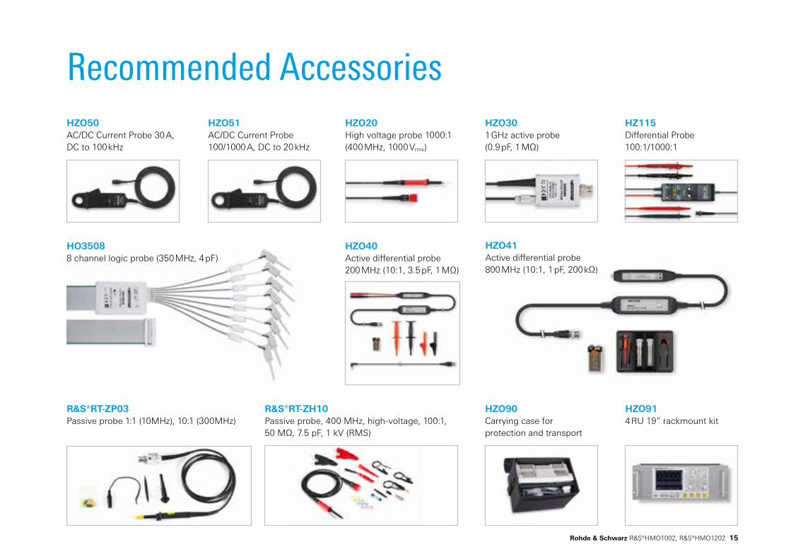
Recommended Accessories
HZO90Carrying case for protection and transport
R&S®RT-ZP03Passive probe 1:1 (10MHz), 10:1 (300MHz)
HZO41Active differential probe 800 MHz (10:1, 1 pF, 200 kΩ)
HZO50AC/DC Current Probe 30 A, DC to 100 kHz
HZO51AC/DC Current Probe 100/1000 A, DC to 20 kHz
R&S®RT-ZH10Passive probe, 400 MHz, high-voltage, 100:1, 50 MΩ, 7.5 pF, 1 kV (RMS)
HZO40Active differential probe 200 MHz (10:1, 3.5 pF, 1 MΩ)
HZO914 RU 19” rackmount kit
HZO20High voltage probe 1000:1 (400 MHz, 1000 Vrms)
HZO301 GHz active probe (0.9 pF, 1 MΩ)
HZ115Differential Probe 100:1/1000:1
HO35088 channel logic probe (350 MHz, 4 pF)
Rohde & Schwarz R&S®HMO1002, R&S®HMO1202 15

PD
360
7.01
52.3
2 V
02.
01 P
DP
1 en
3607015232
© 2015 Rohde & Schwarz GmbH & Co. KG Mühldorfstr. 15, 81671 München, Germany Phone: +49 89 41 29 - 0 Fax: +49 89 41 29 12 164 E-mail: [email protected] Internet: www.rohde-schwarz.com Subject to change – Data without tolerance limits is not binding. R&S® is a registered trademark of Rohde & Schwarz GmbH & Co. KG. Trade names are trademarks of the owners. 01/16