tutorial for wake up schemes and requirements for
TRANSCRIPT
AE-BE/EKE-Ho | 6/4/2012 |
Wake Up for Automotive Communication Networks
Automotive Electronics
Tutorial for Wake Up Schemes and Requirements for Automotive
Communication Networks Presentation supported (alphabetical order) by: Stefan Buntz (Daimler) Thomas Hogenmüller (Robert Bosch) Stephane Korzin (Renault) Kirsten Matheus (BMW Group) Thilo Streichert (Daimler) Thomas Suermann (NXP) Mehmet Tazebay (Broadcom) Norbert Valder (Visteon) Helge Zinner (Continental)
1
AE-BE/EKE-Ho | 6/4/2012 |
Wake Up for Automotive Communication Networks
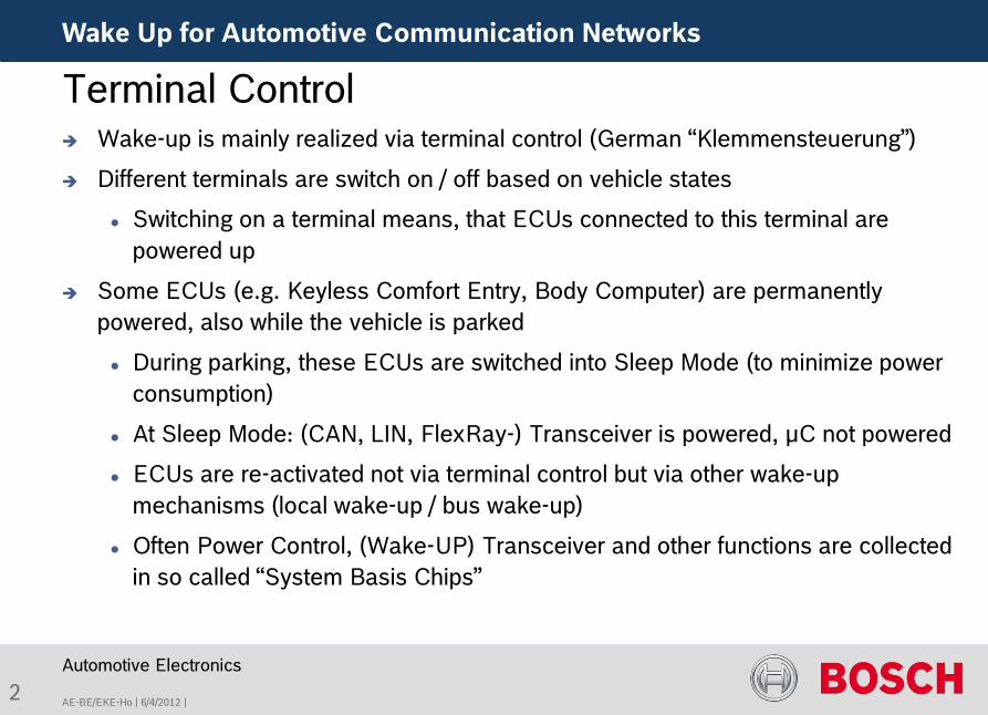
Wake-up is mainly realized via terminal control (German “Klemmensteuerung”)
Different terminals are switch on / off based on vehicle states
Switching on a terminal means, that ECUs connected to this terminal are powered up
Some ECUs (e.g. Keyless Comfort Entry, Body Computer) are permanently powered, also while the vehicle is parked
During parking, these ECUs are switched into Sleep Mode (to minimize power consumption)
At Sleep Mode: (CAN, LIN, FlexRay-) Transceiver is powered, µC not powered
ECUs are re-activated not via terminal control but via other wake-up mechanisms (local wake-up / bus wake-up)
Often Power Control, (Wake-UP) Transceiver and other functions are collected in so called “System Basis Chips”
Automotive Electronics
Terminal Control
2
AE-BE/EKE-Ho | 6/4/2012 |
Wake Up for Automotive Communication Networks
Automotive Electronics
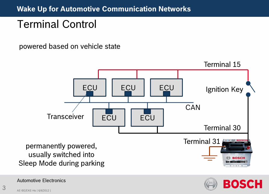
Terminal Control
CAN
Ignition Key
permanently powered, usually switched into
Sleep Mode during parking
powered based on vehicle state
Transceiver
ECU ECU ECU
ECU ECU
3
Terminal 30
Terminal 15
Terminal 31
AE-BE/EKE-Ho | 6/4/2012 |
Wake Up for Automotive Communication Networks
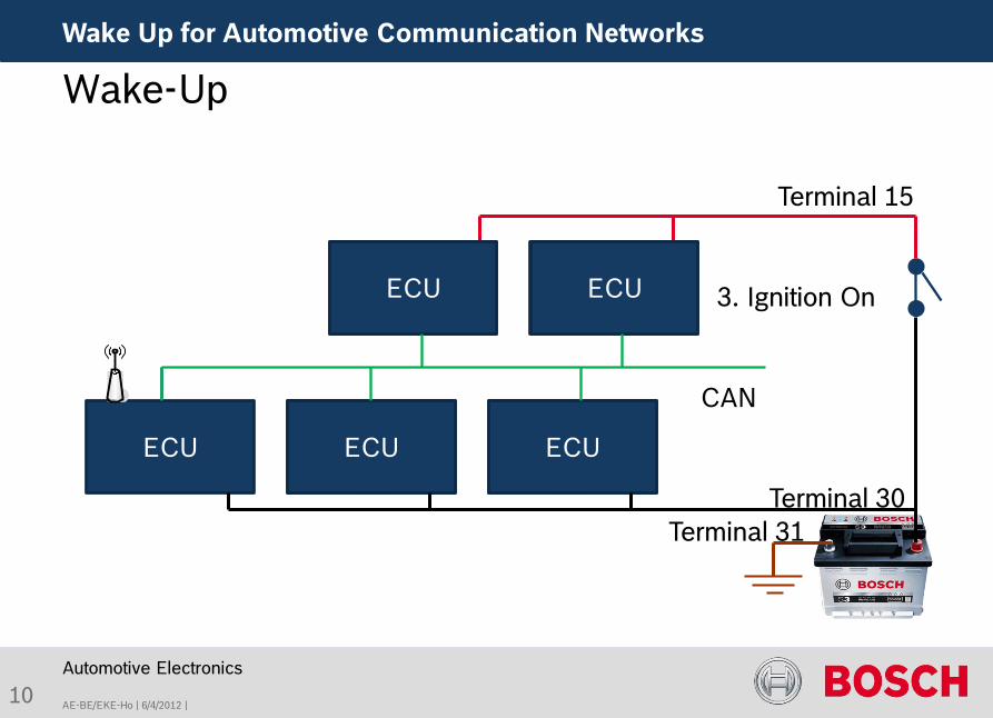
Typically, the terminal control differentiates some general vehicle states Vehicle parked and switched off (locked) Infotainment mode: Driver is in the car but ignition is off Ignition Crank Engine running Pre- / Post-run
As a result there are some typical terminals used in most vehicles, e.g.: Terminal 15: Switched on with ignition on Terminal 30: Permanently on Terminal 30x: Switched on under certain conditions, e.g. for a certain
time to allow for post-run Further terminal numbers can be found at DIN 72552
Automotive Electronics
Terminal Control – Vehicle States
4
AE-BE/EKE-Ho | 6/4/2012 |
Wake Up for Automotive Communication Networks
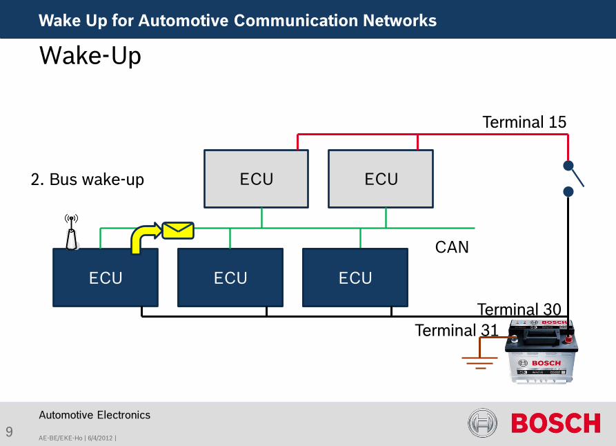
ECUs attached to terminal 30 are switched on permanently, also while the vehicle is parked and locked. The power consumption during this time is taken out of the car battery.
Therefore, the Sleep Mode current of these ECUs must be extremely low (in the range of µA). 100 µA requirement
To re-activate the ECUs, there could be a local wake-up source (e.g. a switch attached to the ECU of a receiver for a remote key) or a bus wake-up.
Normally, the first ECU is woken up by a local wake-up source and then (if needed) wakes up all other ECUs within this cluster via bus wake-up
Automotive Electronics
Bus Wake-Up
5
AE-BE/EKE-Ho | 6/4/2012 |
Wake Up for Automotive Communication Networks
Automotive Electronics
6
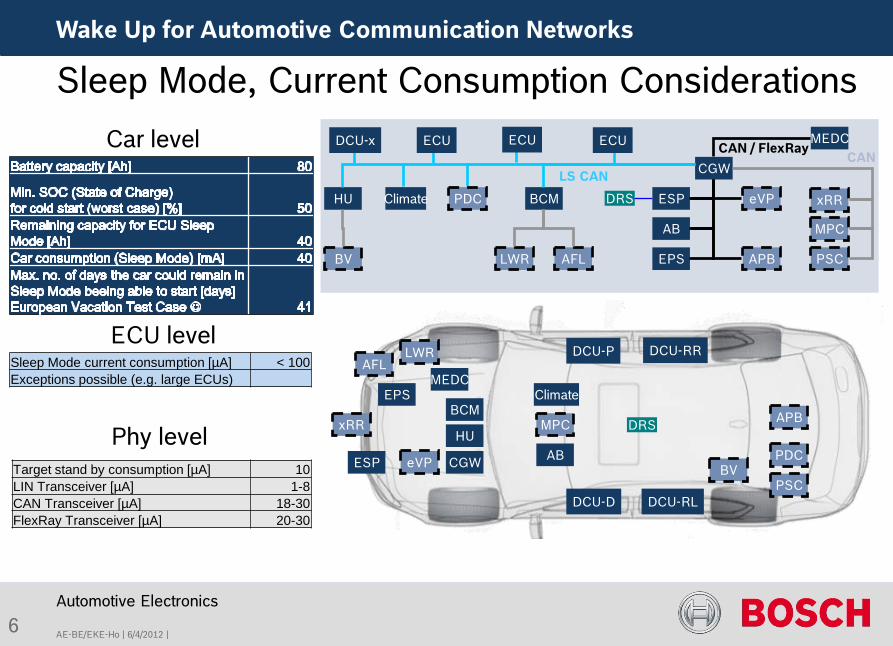
Sleep Mode, Current Consumption Considerations
EPS
AB
MEDC
CGW
xRR ESP
MPC
PSC
BCM eVP HU
EPS
AB
MEDC
CGW
xRR
ESP
MPC
PSC
BCM
eVP
HU
BV
BV
DRS
DRS
AFL
AFL
APB
APB
LWR
DCU-x ECU
Climate
ECU ECU
DCU-D
DCU-P
DCU-RL
DCU-RR
Climate
LWR
PDC
PDC
LS CAN
CAN / FlexRay CAN
Car level
ECU level
Phy level
Sleep Mode current consumption [µA] < 100 Exceptions possible (e.g. large ECUs)
Target stand by consumption [µA] 10 LIN Transceiver [µA] 1-8 CAN Transceiver [µA] 18-30 FlexRay Transceiver [µA] 20-30
7 AE-BE/EKE | 08.02.2011 |
Wake Up for Automotive Communication Networks
Automotive Electronics
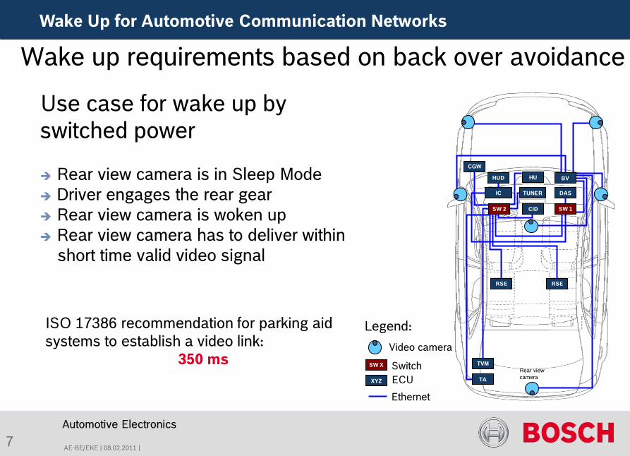
Wake up requirements based on back over avoidance Use case for wake up by switched power
Rear view camera is in Sleep Mode Driver engages the rear gear Rear view camera is woken up Rear view camera has to deliver within short time valid video signal
CGW
HUD
TA
RSE
TVM
RSE
HU
TUNER DAS
SW 1
IC
CID
BV
SW 2
Video camera
Ethernet
SW X Switch XYZ ECU
Legend:
Rear view camera
ISO 17386 recommendation for parking aid systems to establish a video link:
350 ms
AE-BE/EKE-Ho | 6/4/2012 |
Wake Up for Automotive Communication Networks
Automotive Electronics
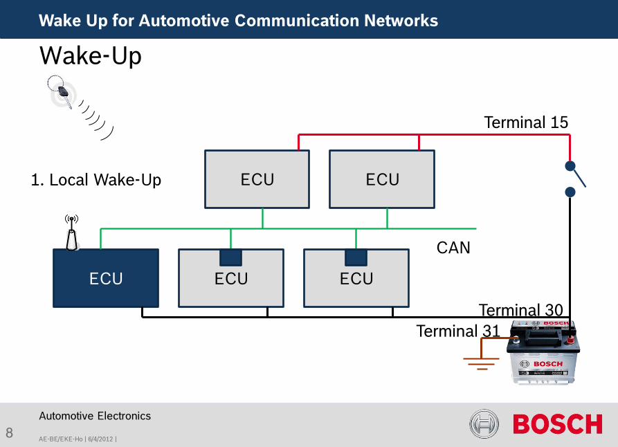
Wake-Up
8
ECU
1. Local Wake-Up
ECU ECU
ECU ECU
CAN
Terminal 15
Terminal 30 Terminal 31
AE-BE/EKE-Ho | 6/4/2012 |
Wake Up for Automotive Communication Networks
Automotive Electronics
Wake-Up
ECU
2. Bus wake-up
ECU ECU
ECU ECU
CAN
ECU ECU
9
Terminal 15
Terminal 30 Terminal 31
AE-BE/EKE-Ho | 6/4/2012 |
Wake Up for Automotive Communication Networks
Automotive Electronics
Wake-Up
10
ECU
3. Ignition On
ECU ECU
ECU ECU
CAN
ECU ECU
Terminal 15
Terminal 30
ECU ECU
Terminal 31
AE-BE/EKE-Ho | 6/4/2012 |
Wake Up for Automotive Communication Networks
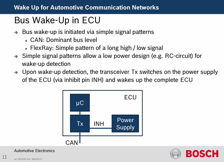
Bus wake-up is initiated via simple signal patterns CAN: Dominant bus level FlexRay: Simple pattern of a long high / low signal
Simple signal patterns allow a low power design (e.g. RC-circuit) for wake-up detection
Upon wake-up detection, the transceiver Tx switches on the power supply of the ECU (via inhibit pin INH) and wakes up the complete ECU
Automotive Electronics
Bus Wake-Up in ECU
CAN
Tx Power Supply INH
µC
Power Supply
µC ECU
11
AE-BE/EKE-Ho | 6/4/2012 |
Wake Up for Automotive Communication Networks
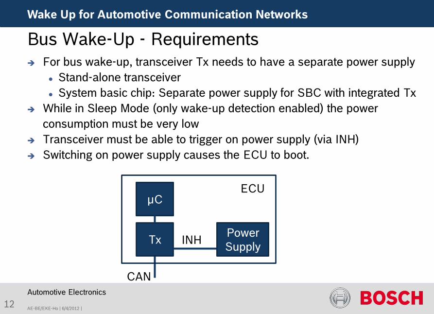
For bus wake-up, transceiver Tx needs to have a separate power supply Stand-alone transceiver System basic chip: Separate power supply for SBC with integrated Tx
While in Sleep Mode (only wake-up detection enabled) the power consumption must be very low
Transceiver must be able to trigger on power supply (via INH) Switching on power supply causes the ECU to boot.
Automotive Electronics
Bus Wake-Up - Requirements
CAN
Tx Power Supply INH
µC
Power Supply
µC ECU
12
AE-BE/EKE-Ho | 6/4/2012 |
Wake Up for Automotive Communication Networks
Automotive Electronics
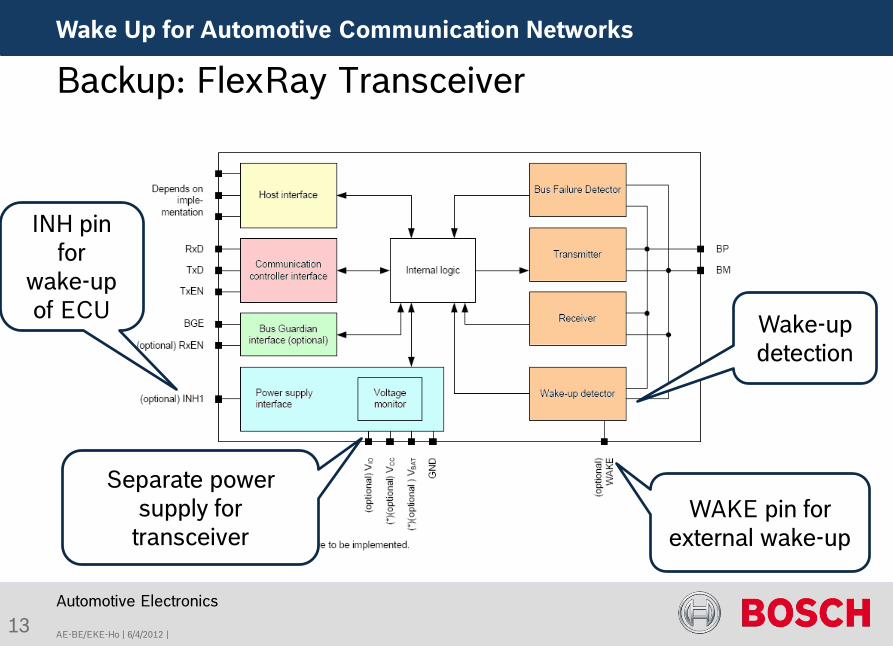
Backup: FlexRay Transceiver
Separate power supply for
transceiver
INH pin for
wake-up of ECU Wake-up
detection
WAKE pin for external wake-up
13
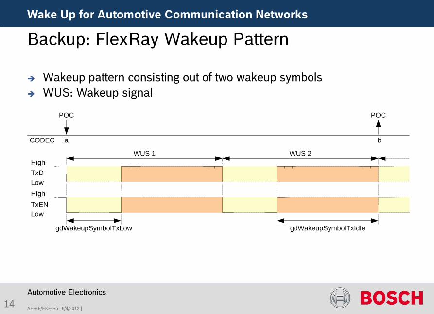
WUS 1 WUS 2
gdWakeupSymbolTxLow
High
LowTxD
High
LowTxEN
a b
POC
CODEC
POC
gdWakeupSymbolTxIdle
AE-BE/EKE-Ho | 6/4/2012 |
Wake Up for Automotive Communication Networks
Automotive Electronics
Backup: FlexRay Wakeup Pattern
Wakeup pattern consisting out of two wakeup symbols WUS: Wakeup signal
14
AE-BE/EKE-Ho | 6/4/2012 |
Wake Up for Automotive Communication Networks
Automotive Electronics
15
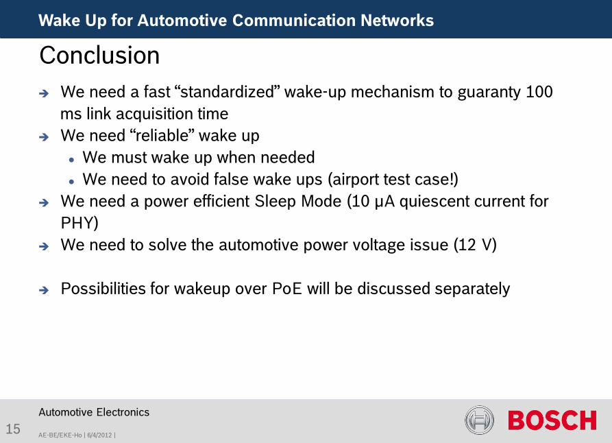
Conclusion We need a fast “standardized” wake-up mechanism to guaranty 100
ms link acquisition time We need “reliable” wake up
We must wake up when needed We need to avoid false wake ups (airport test case!)
We need a power efficient Sleep Mode (10 µA quiescent current for PHY)
We need to solve the automotive power voltage issue (12 V)
Possibilities for wakeup over PoE will be discussed separately
AE-BE/EKE-Ho | 6/4/2012 |
Wake Up for Automotive Communication Networks
Automotive Electronics
16
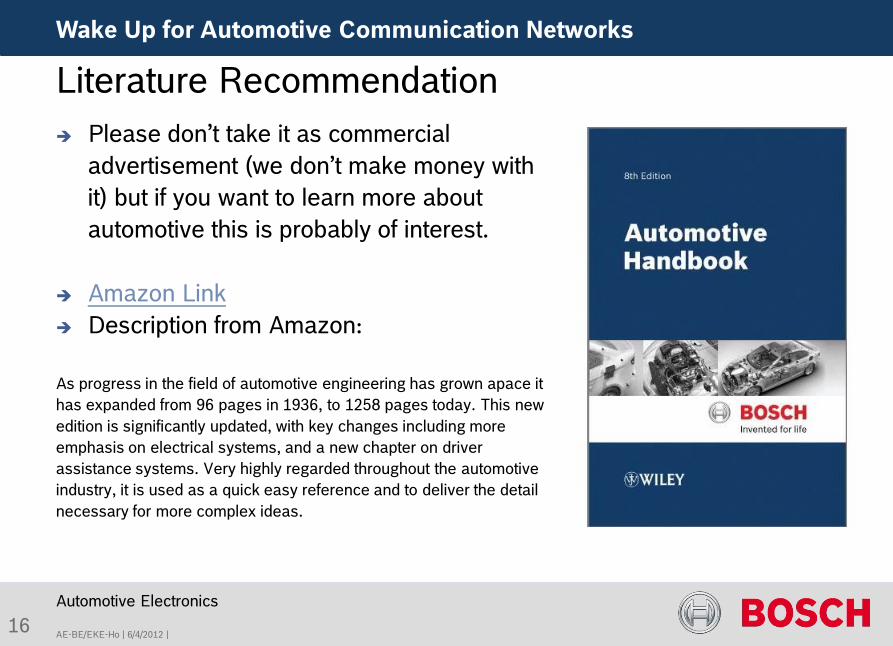
Literature Recommendation Please don’t take it as commercial
advertisement (we don’t make money with it) but if you want to learn more about automotive this is probably of interest.
Amazon Link Description from Amazon:
As progress in the field of automotive engineering has grown apace it has expanded from 96 pages in 1936, to 1258 pages today. This new edition is significantly updated, with key changes including more emphasis on electrical systems, and a new chapter on driver assistance systems. Very highly regarded throughout the automotive industry, it is used as a quick easy reference and to deliver the detail necessary for more complex ideas.