turning wooden spokes on a lathe
TRANSCRIPT
8/6/2019 Turning Wooden Spokes on a Lathe
http://slidepdf.com/reader/full/turning-wooden-spokes-on-a-lathe 1/4
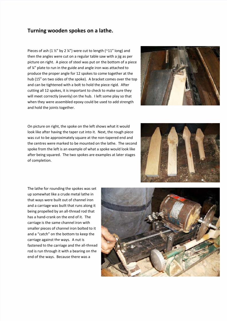
Turning wooden spokes on a lathe. Pieces of ash (1 ½” by 2 ¼”) were cut to length (~11” long) and
then the angles were cut on a regular table saw with a jig as per
picture on right. A piece of steel was put on the bottom of a piece
of ¼” plate to run in the guide and angle iron was attached to
produce the proper angle for 12 spokes to come together at the
hub (15o on two sides of the spoke). A bracket comes over the top
and can be tightened with a bolt to hold the piece rigid. After
cutting all 12 spokes, it is important to check to make sure they
will meet correctly (evenly) on the hub. I left some play so that
when they were assembled epoxy could be used to add strength
and hold the joints together.
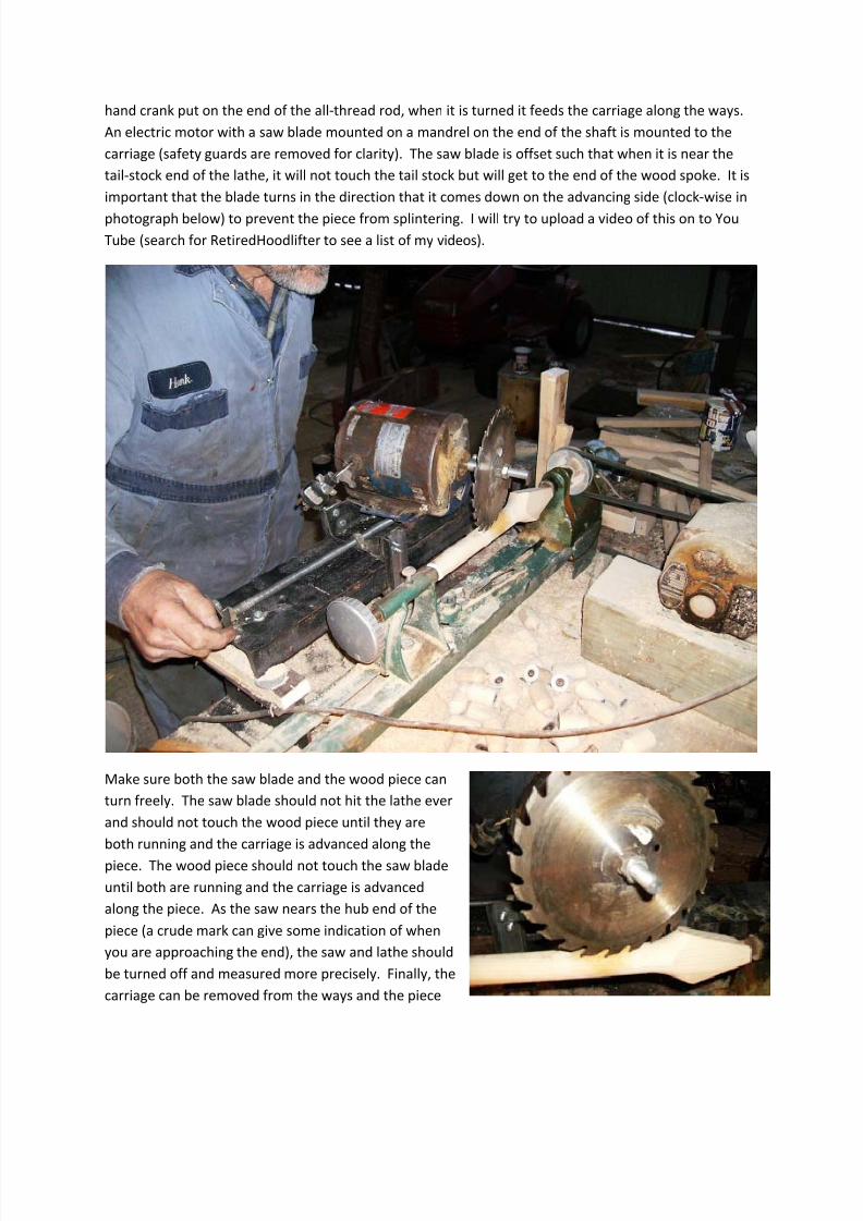
On picture on right, the spoke on the left shows what it would
look like after having the taper cut into it. Next, the rough piece
was cut to be approximately square at the non‐tapered end and
the centres were marked to be mounted on the lathe. The second
spoke from the left is an example of what a spoke would look like
after being squared. The two spokes are examples at later stages
of completion.
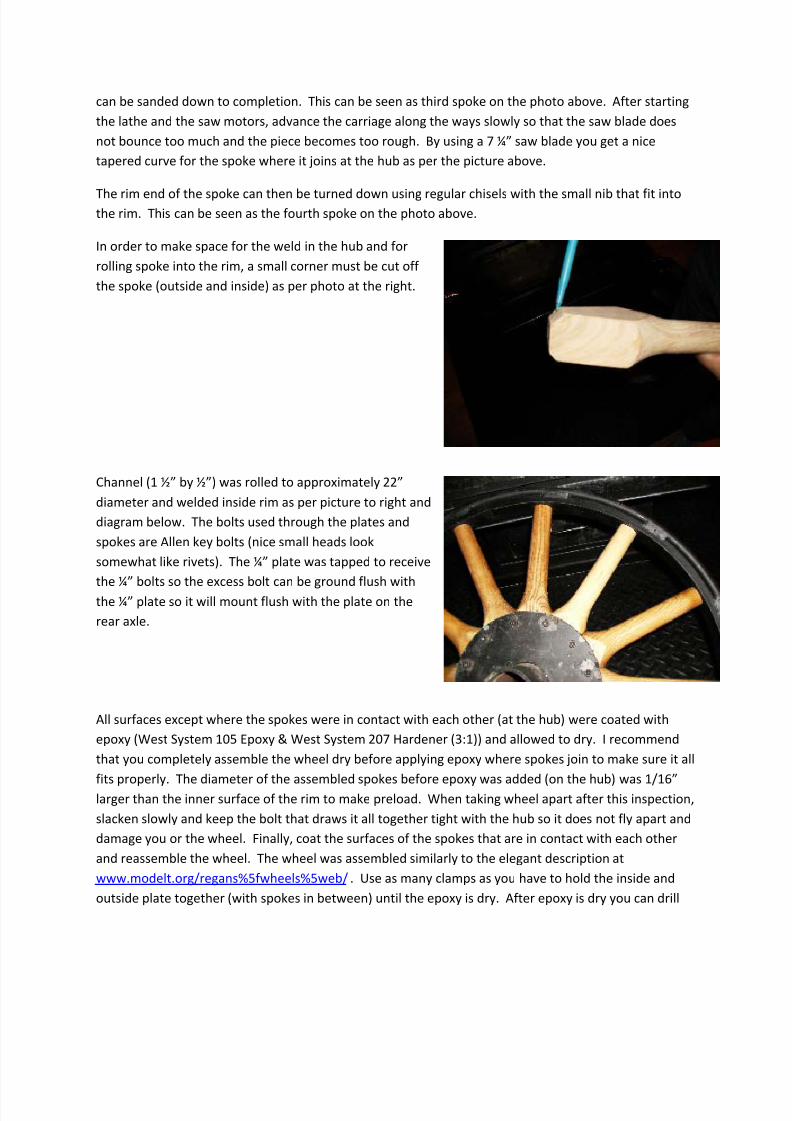
The lathe for rounding the spokes was set
up somewhat like a crude metal lathe in
that ways were built out of channel iron
and a carriage was built that runs along it
being propelled by an all‐thread rod that
has a hand‐crank on the end of it. The
carriage is the same channel iron with
smaller pieces of channel iron bolted to it
and a “catch” on the bottom to keep the
carriage against the ways. A nut is
fastened to the carriage and the all‐thread
rod is run through it with a bearing on the
end of the ways. Because there was a
8/6/2019 Turning Wooden Spokes on a Lathe
http://slidepdf.com/reader/full/turning-wooden-spokes-on-a-lathe 2/4
hand crank put on the end of the all‐thread rod, when it is turned it feeds the carriage along the ways.
An electric motor with a saw blade mounted on a mandrel on the end of the shaft is mounted to the
carriage (safety guards are removed for clarity). The saw blade is offset such that when it is near the
tail‐stock end of the lathe, it will not touch the tail stock but will get to the end of the wood spoke. It is
important that the blade turns in the direction that it comes down on the advancing side (clock‐wise in
photograph below) to prevent the piece from splintering. I will try to upload a video of this on to You
Tube (search for RetiredHoodlifter to see a list of my videos).
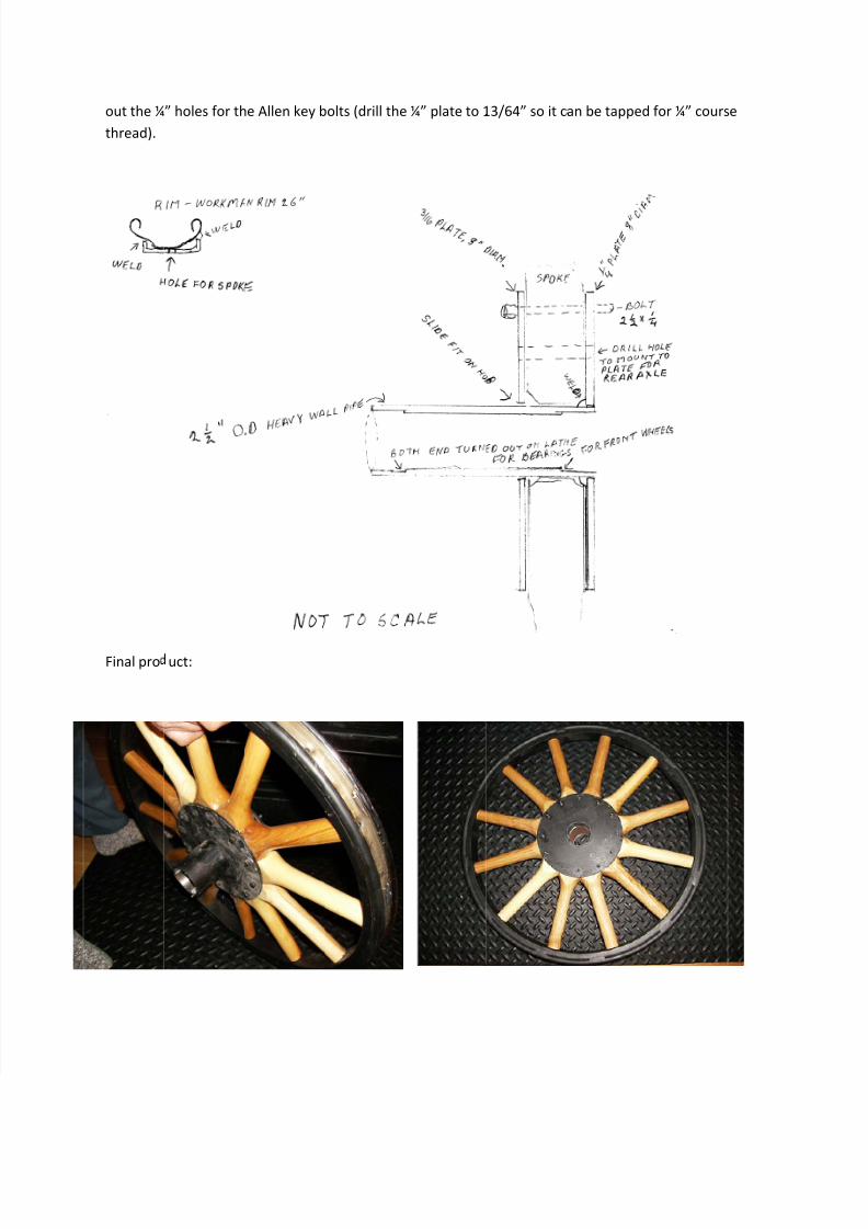
Make sure both the saw blade and the wood piece can
turn freely. The saw blade should not hit the lathe ever
and should not touch the wood piece until they are
both running and the carriage is advanced along the
piece. The wood piece should not touch the saw blade
until both are running and the carriage is advanced
along the piece. As the saw nears the hub end of the
piece (a crude mark can give some indication of when
you are approaching the end), the saw and lathe should
be turned off and measured more precisely. Finally, the
carriage can be removed from the ways and the piece
8/6/2019 Turning Wooden Spokes on a Lathe
http://slidepdf.com/reader/full/turning-wooden-spokes-on-a-lathe 3/4
can be sanded down to completion. This can be seen as third spoke on the photo above. After starting
the lathe and the saw motors, advance the carriage along the ways slowly so that the saw blade does
not bounce too much and the piece becomes too rough. By using a 7 ¼” saw blade you get a nice
tapered curve for the spoke where it joins at the hub as per the picture above.
The rim end of the spoke can then be turned down using regular chisels with the small nib that fit into
the rim. This can be seen as the fourth spoke on the photo above.
In order to make space for the weld in the hub and for
rolling spoke into the rim, a small corner must be cut off
the spoke (outside and inside) as per photo at the right.
Channel (1 ½” by ½”) was rolled to approximately 22”
diameter and welded inside rim as per picture to right and
diagram below. The bolts used through the plates and
spokes are Allen key bolts (nice small heads look
somewhat like rivets). The ¼” plate was tapped to receive
the ¼” bolts so the excess bolt can be ground flush with
the ¼” plate so it will mount flush with the plate on the
rear axle.
All surfaces except where the spokes were in contact with each other (at the hub) were coated with
epoxy (West System 105 Epoxy & West System 207 Hardener (3:1)) and allowed to dry. I recommend
that you completely assemble the wheel dry before applying epoxy where spokes join to make sure it all
fits
properly.
The
diameter
of
the
assembled
spokes
before
epoxy
was
added
(on
the
hub)
was
1/16”
larger than the inner surface of the rim to make preload. When taking wheel apart after this inspection,
slacken slowly and keep the bolt that draws it all together tight with the hub so it does not fly apart and
damage you or the wheel. Finally, coat the surfaces of the spokes that are in contact with each other
and reassemble the wheel. The wheel was assembled similarly to the elegant description at
www.modelt.org/regans%5fwheels%5web/ . Use as many clamps as you have to hold the inside and
outside plate together (with spokes in between) until the epoxy is dry. After epoxy is dry you can drill
8/6/2019 Turning Wooden Spokes on a Lathe
http://slidepdf.com/reader/full/turning-wooden-spokes-on-a-lathe 4/4
out the ¼thread).
Final pro
” holes for th
uct:
e Allen key bolts (drill the ¼” plate to 1
3/64” so it can be tapped for ¼” cours
e