turning inserts classification manufacturing... · wiper insert for light cutting of carbon steel...
TRANSCRIPT

A044
12°
12°
8°
16°
15° .008"
15°
14°
9°
14°
9°
14°
14°
15°
15°
.013"
8°25°
.012"10°
25°
TUR
NIN
G IN
SER
TSTURNING INSERTS
CLASSIFICATIONNEGATIVE INSERTS WITH HOLE
Tole
ranc
eAp
plica
tion
Breaker Nameand
PictureFeatures Cross Section
Geometry
Carbon Steel·Alloy Steel Nose
Flank
f (inch/rev)
ap ( i
nch)
First recommendation for finishing carbon steel, alloy steel and stainless steelDouble sided chipbreaker.Stable chip control even at small depth of cut.
M C
lass
Alternative breaker for finishing mild steelDouble sided chipbreaker.Stable chip control even at small depth of cut.Sharp edge gives best performance.
Mild Steel Nose
ap ( i
nch)
Flank
f (inch/rev)
NoseMild Steel
ap ( i
nch)
Flank
f (inch/rev)
First recommendation for finishing mild steelDouble sided chipbreaker.Effectively controls chips.Suitable for mild steel finishing.
Fini
sh C
uttin
g
First recommendation for finishing difficult-to-cut materialsDouble sided chipbreaker.Ideal for heat-resistant alloy.The sharp edge produces good cutting surface.The curved edge allows smooth chip discharge.
Difficult-to-Cut Materials Nose
ap ( i
nch)
Flank
f (inch/rev)
Titanium alloy Nose
Flank
f (inch/rev)
First recommendation for finishing titanium alloyDouble sided chipbreaker.Ideal for aluminum and copper.The sharp edge produces excellent surface finishes.The curved edge allows smooth chip discharge.The polished insert face prevents built up edge.
G C
lass
Alternative breaker for finishing carbon steel and alloy steelDouble sided chipbreaker.G class insert tolerance is suitable for workpieces requiring close dimensional tolerances. Stable chip control even at small depth of cut.
Carbon Steel·Alloy Steel Nose
Flankap ( i
nch)
f (inch/rev)
Carbon Steel·Alloy SteelFlank
ap ( i
nch)
f (inch/rev)
Precise finishingDouble sided chipbreaker.A narrow angled chipbreaker for good control.The sharp edge produces a good surface finish.
FinishingDouble sided chipbreaker.Angled chipbreaker controls chip flow.The sharp edge produces a good chip discharge.
Carbon Steel·Alloy SteelFlank
ap ( i
nch)
f (inch/rev)
Carbon Steel·Alloy Steel Nose
ap ( i
nch)
Flank
f (inch/rev)
M C
lass
Ligh
t Cut
ting
ap ( i
nch)
First recommendation for light cutting of carbon steel and alloy steelDouble sided chipbreaker.Stable chip control in light cutting range.The curved edge allows smooth chip discharge.

A046
.008"15°
.006"7°
18°
15°
.006"7°
18°
.008"15°
.010"14°
9°
13°
9°
13°
.008"10°
10°
12°
12°
.008"15°
12°
12°
8°
16°
15° .008"
15°
14°
9°
14°
9°
14°
14°
15°
15°
.013"
8°25°
.012"10°
25°
.008"15°
.006"7°
18°
15°
.006"7°
18°
.008"15°
.010"14°
9°
13°
9°
13°
.008"10°
10°
12°
12°
.008"15°
.008"15°
.006"7°
18°
15°
.006"7°
18°
.008"15°
.010"14°
9°
13°
9°
13°
.008"10°
10°
12°
12°
.008"15°
TUR
NIN
G IN
SER
TSTURNING INSERTS
CLASSIFICATIONNEGATIVE INSERTS WITH HOLE
M C
lass
G C
lass
Ligh
t Cut
ting
M C
lass
Tole
ranc
eAp
plica
tion
Breaker Nameand
PictureFeatures Cross Section
Geometry
First recommendation for light cutting of carbon steel, alloy steel and stainless steelDouble sided chipbreaker.Can be used at low depth of cuts and high feed rates.The curved edge allows smooth chip discharge.Recommended for workpieces in the 160─250HB range.
Carbon Steel·Alloy Steel Nose
ap ( i
nch)
f (inch/rev)
Flank
NoseCarbon Steel·Alloy Steel
ap ( i
nch)
Flank
f (inch/rev)
Wiper insert for light cutting of carbon steel and alloy steelDouble sided chipbreaker.The wiper allows up to two times higher feed.Wiper design for increased productivity and improved surface finish.
First recommendation for light cutting of mild steelDouble sided chipbreaker.Effectively controls chips.Recommended for workpieces in the 200─300HB range.
Mild Steel
ap ( i
nch)
Nose
Flank
f (inch/rev)
NoseCarbon Steel·Alloy Steel
Flank
f (inch/rev)
ap ( i
nch)
Alternative breaker for light cutting of carbon steel and alloy steelDouble sided chipbreaker.Can be used at small depth of cuts.The curved edge allows smooth chip discharge.
FlankCarbon Steel·Alloy Steel
ap ( i
nch)
f (inch/rev)
Alternative chipbreaker for light cutting of carbon steel and alloy steelDouble sided chipbreaker.Angled chipbreaker controls chip flow.Excellent chip control at low to medium feed rates.
Light cuttingDouble sided chipbreaker.Parallel chipbreaker.Excellent chip control at low to medium feed rates.
First recommendation for light cutting of difficult-to-cut materialsDouble sided chipbreaker.Ideal for heat-resistant alloy and titanium alloy.The sharp edge produces excellent surface finishes.The curved edge allows smooth chip discharge. f (inch/rev)
ap ( i
nch)
Flank
NoseDifficult-to-Cut Materials
f (inch/rev)
ap ( i
nch)
FlankCarbon Steel·Alloy Steel
Carbon Steel·Alloy Steel Nose
ap ( i
nch)
Flank
f (inch/rev)
Alternative breaker for light cutting of carbon steel and alloy steelDouble sided chipbreaker.Superior chip control at small depth of cuts.Covers copying and back turning with wavy edge.Recommended for workpieces in the 200─300HB range.
Stainless Steel Nose
ap ( i
nch)
Flank
f (inch/rev)
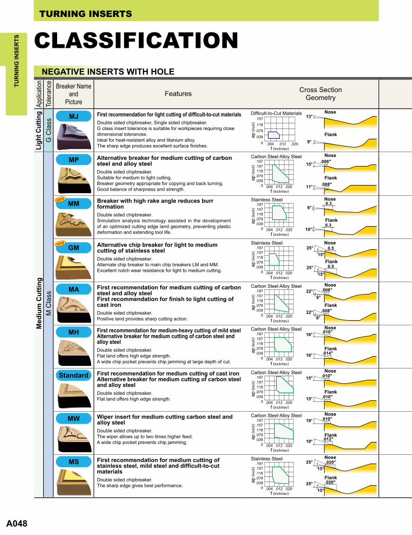
First recommendation for light cutting of stainless steelDouble sided chipbreaker.Stable chip control in light cutting range.Breaker with high rake angle provides excellent burr control.
A048
MM
GM
.008"15°
.006"7°
18°
15°
.006"7°
18°
.008"15°
.010"14°
9°
13°
9°
13°
.008"10°
10°
12°
12°
.008"15°
TUR
NIN
G IN
SER
TSTURNING INSERTS
CLASSIFICATIONNEGATIVE INSERTS WITH HOLE
M C
lass
Med
ium
Cut
ting
Tole
ranc
eAp
plica
tion
Breaker Nameand
PictureFeatures Cross Section
Geometry
First recommendation for medium cutting of carbon steel and alloy steelFirst recommendation for finish to light cutting of cast ironDouble sided chipbreaker.Positive land provides sharp cutting action.
Carbon Steel·Alloy Steel
ap ( i
nch)
f (inch/rev)
Nose
Flank
Carbon Steel·Alloy Steel Nose
Flankap ( i
nch)
f (inch/rev)
Alternative breaker for medium cutting of carbon steel and alloy steelDouble sided chipbreaker.Suitable for medium to light cutting.Breaker geometry appropriate for copying and back turning.Good balance of sharpness and strength.
First recommendation for medium-heavy cutting of mild steelAlternative breaker for medium cutting of carbon steel and alloy steelDouble sided chipbreaker.Flat land offers high edge strength.A wide chip pocket prevents chip jamming at large depth of cut.
ap ( i
nch)
ap ( i
nch)
ap ( i
nch)
ap ( i
nch)
Carbon Steel·Alloy Steel
Carbon Steel·Alloy Steel
Carbon Steel·Alloy Steel
Stainless Steel
f (inch/rev)
f (inch/rev)
f (inch/rev)
f (inch/rev)
Nose
Nose
Nose
Nose
Flank
Flank
Flank
Flank
Standard First recommendation for medium cutting of cast ironAlternative breaker for medium cutting of carbon steel and alloy steelDouble sided chipbreaker.Flat land offers high edge strength.
Wiper insert for medium cutting carbon steel and alloy steelDouble sided chipbreaker.The wiper allows up to two times higher feed.A wide chip pocket prevents chip jamming.
First recommendation for medium cutting of stainless steel, mild steel and difficult-to-cut materialsDouble sided chipbreaker.The sharp edge gives best performance.
Ligh
t Cut
ting
G C
lass
First recommendation for light cutting of difficult-to-cut materialsDouble sided chipbreaker, Single sided chipbreaker.G class insert tolerance is suitable for workpieces requiring close dimensional tolerances.Ideal for heat-resistant alloy and titanium alloy.The sharp edge produces excellent surface finishes. f (inch/rev)
Flankap ( i
nch)
Difficult-to-Cut Materials Nose
Nose
Nose
Flank
Flank
Breaker with high rake angle reduces burr formationDouble sided chipbreaker.Simulation analysis technology assisted in the development of an optimized cutting edge land geometry, preventing plastic deformation and extending tool life.
Alternative chip breaker for light to medium cutting of stainless steelDouble sided chipbreaker.Alternate chip breaker to main chip breakers LM and MM.Excellent notch wear resistance for light to medium cutting.
ap ( i
nch)
ap ( i
nch)
Stainless Steel
Stainless Steel
f (inch/rev)
f (inch/rev)

A050
RP
RM
0.33
3°0.33
6°
0.323°
0.32
TUR
NIN
G IN
SER
TSTURNING INSERTS
CLASSIFICATIONNEGATIVE INSERTS WITH HOLE
Hea
vy C
uttin
gM
Cla
ssM
Cla
ssR
ough
Cut
ting
G C
lass
Tole
ranc
eAp
plica
tion
Breaker Nameand
PictureFeatures Cross Section
Geometry
Medium cuttingDouble sided chipbreaker.Parallel chipbreaker.Good chip control for medium feed rate.
First recommendation for rough cutting ofcarbon steel, alloy steel and stainless steelDouble sided chipbreaker.For interrupted cut and removing scale.A combination of wide land and large chip pocket allows high feeds.
First recommendation for rough cutting ofdifficult-to-cut materialsDouble sided chipbreaker.Excellent balance of edge sharpness and strength.Edge geometry with high face wear resistance.
First recommendation for heavy cutting of mild steeland stainless steelSingle sided chipbreaker.Appropriate for the lower end of the heavy cutting region.Low cutting resistance due to positive land and curved edge.Teardrop dots improve chip control without increasing cutting resistance.
First recommendation for heavy cutting of carbon steel and alloy steelSingle sided chipbreaker.Appropriate for the medium range of the heavy cutting region.The flat edge and chamfer, provide a balance of sharpness and strength.Variable land and a wavy chipbreaker for good chip control.
Carbon Steel·Alloy Steel
Carbon Steel·Alloy Steel
Carbon Steel·Alloy Steel
Stainless Steel
Carbon Steel·Alloy Steel
Difficult-to-Cut Materials
Mild Steel
Flank
Flank
Flank
Flank
Flank
Flank
Flank
Nose
Nose
Nose
Nose
Nose
Nose
ap ( i
nch)
ap ( i
nch)
ap ( i
nch)
ap ( i
nch)
ap ( i
nch)
ap ( i
nch)
ap ( i
nch)
f (inch/rev)
f (inch/rev)
f (inch/rev)
f (inch/rev)
f (inch/rev)
f (inch/rev)
f (inch/rev)
M C
lass
Med
ium
Cut
ting
ap ( i
nch)
Stainless Steel
f (inch/rev)
FlankAlternative chipbreaker for medium cutting of stainless steelDouble sided chipbreaker.Good balance of edge strength and sharpness.Right- or left-hand breaker for unidirectional chip control.
Alternative chipbreaker for medium cutting ofcarbon steel and alloy steelDouble sided chipbreaker.Parallel chipbreaker controls chip flow. Good chip control for medium feed rates.
Carbon Steel·Alloy Steel
ap ( i
nch)
f (inch/rev)
Flank
First recommendation for rough cutting of carbon and alloy steelDouble sided chipbreaker.For interrupted cutting and cutting through scale.Good balance of cutting edge strength and low cutting resistance.
First recommendation for rough cutting of stainless steelDouble sided chipbreaker.Excellent fracture resistance during interrupted cutting due to the optimum cutting edge land angle and honing geometry.

A052
FP
FM
TUR
NIN
G IN
SER
TSTURNING INSERTS
CLASSIFICATIONNEGATIVE INSERTS WITH HOLE
G C
lass
M C
lass
For C
ast I
ron
Tole
ranc
eAp
plica
tion
First recommendation for rough cutting of cast ironDouble sided flat insert.Most effective in unstable machining i.e. interrupted cuts due to high edge strength and stable fitting on the shim.
For cast ironDouble sided flat insert.Most effective in unstable machining i.e. interrupted cuts due to high edge strength and stable fitting on the shim.G class tolerance for use on workpieces requiring close tolerances.
Breaker Nameand
Picture
Flat Top
Flat Top
Features Cross SectionGeometry
Cast Iron
ap ( i
nch)
f (inch/rev)
Cast Iron
ap ( i
nch)
f (inch/rev)
Heav
y Cu
tting
M C
lass
Alternative chipbreaker for heavy cutting of carbon steel and alloy steelSingle sided chipbreaker.Appropriate for the upper end of the heavy cutting region.Wide land and large chamfer offer high edge strength.A wide chipbreaker prevents chip jamming.
Carbon Steel·Alloy Steel
Flank
Nose
ap ( i
nch)
f (inch/rev)
5° POSITIVE INSERTS WITH HOLE
Fini
sh C
uttin
gM
Cla
ssTo
lera
nce
Appli
catio
n
First recommendation for finishing carbon steel,alloy steel, mild steel and stainless steelSuitable for low depth of cut and feed rate applications.Sharp cutting edge and low resistance design provide excellent cuttingperformance.
Breaker Nameand
Picture
Finishing difficult-to-cut materialsThe curved cutting edges support changes in cutting depth-smoothchip discharge and disposal.The high rake angle is highly suitable for finishing diffcult-to-cut materials.
Features Cross SectionGeometry
Carbon Steel·Alloy Steel
Carbon Steel·Alloy Steel
Stainless Steel
Nose
Nose
Nose
ap ( i
nch)
ap ( i
nch)
ap ( i
nch)
Flank
Flank
Flank
f (inch/rev)
f (inch/rev)
f (inch/rev)
Difficult-to-Cut Materials Nose
ap ( i
nch)
Flank
f (inch/rev)
G C
lass
First recommendation for finishing carbon steel and alloy steelChip breaker peninsula controls chips even at small depth of cut.Maintains the edge strength at the corner and prevents sudden fractures.
First recommendation for finishing stainless steelChip breaker peninsula controls chips even at small depth of cut.Maintains the edge strength at the corner and prevents sudden fractures.

A054
LP
MP
MM
LM
18°
8°
18°
8°
18°
18°
0.1
0.1
18°
18°
0.1
0.1
TUR
NIN
G IN
SER
TSTURNING INSERTS
CLASSIFICATION5° POSITIVE INSERTS WITH HOLE
M C
lass
M C
lass
Ligh
t Cut
ting
G C
lass
G C
lass
Fini
sh C
uttin
gTo
lera
nce
Appli
catio
nM
ediu
m C
uttin
g
Breaker Nameand
Picture
Finishing titanium alloyIdeal for aluminum and copper.The sharp edge produces excellent surface finishes.The curved edge allows smooth chip discharge.The polished insert face prevents built up edge.
Finishing carbon steel and alloy steelAngled chipbreaker controls chip flow. Sharp cutting edge produces excellent surface finishes.
Light cutting of carbon steel, alloy steel, mild steeland stainless steelThe double breaker design promotes chip discharge for mild steel low depth of cut a applications.
Light cutting of difficult-to-cut materialsIdeal for heat-resistant alloy and titanium alloyThe curved cutting edges support changes in cutting depth-smooth chip discharge and disposal.The high rake angle is highly suitable for finish-light cutting difficult-to-cut materials.
Light cutting for titanium alloyIdeal for aluminum and copper.The sharp edge produces excellent surface finishes.The curved edge allows smooth chip discharge.The polished insert face prevents built up edge.
Features Cross SectionGeometry
Titanium alloy Nose
ap ( i
nch)
ap ( i
nch)
ap ( i
nch)
Flank
f (inch/rev)
f (inch/rev)
f (inch/rev)
Carbon Steel·Alloy SteelFlank
ap ( i
nch)
ap ( i
nch)
ap ( i
nch)
f (inch/rev)
f (inch/rev)
f (inch/rev)
Carbon Steel·Alloy Steel Nose
Nose
Nose
ap ( i
nch)
Flank
Flank
Flank
f (inch/rev)
Difficult-to-Cut Materials Nose
ap ( i
nch)
Flank
f (inch/rev)
Titanium alloy
ap ( i
nch)
Flank
Flank
Flank
f (inch/rev)
Nose
Nose
Nose
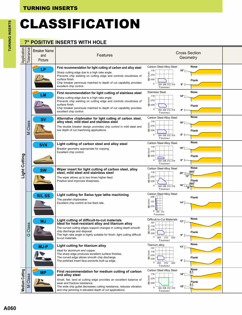
First recommendation for light cutting of carbon and alloy steelSharp cutting edge due to a high rake angle.Prevents chip welding on cutting edge and controls cloudiness of surface finish.Chip breaker peninsula matched to depth of cut capability provides excellent chip control.
First recommendation for light cutting of carbon and alloy steelSharp cutting edge due to a high rake angle.Prevents chip welding on cutting edge and controls cloudiness of surface finish.Chip breaker peninsula matched to depth of cut capability provides excellent chip control.
First recommendation for light cutting of carbon and alloy steelSmall, flat, land at cutting edge provides an excellent balance of wear and fracture resistance.The wide chip gullet decreases cutting resistance, reduces vibration and chip jamming in elevated depth of cut applications.
First recommendation for medium cutting of stainless steelGood balance of wear resistance and fracture resistance because of the flat land cutting edge.A wide chip pocket controls increasing of the cutting resistance and reduces vibration and chip jamming even at large depth of cut.
Carbon Steel·Alloy Steel
Carbon Steel·Alloy Steel
Stainless Steel
Stainless Steel

A056
20°
20°
30°
TUR
NIN
G IN
SER
TSTURNING INSERTS
CLASSIFICATION5° POSITIVE INSERTS WITH HOLE
E C
lass
M C
lass
Tole
ranc
eM
ediu
m C
uttin
gAp
plica
tion
Breaker Nameand
Picture
Medium cutting of carbon steel, alloy steel and stainless steelThe high rake angle combined with a small flat land provide a balance of strength and sharpness.
Medium cutting for Swiss type lathe machiningFeatures a high angled chipbreaker.Low resistance insert design controls chip flow.
General purpose for Swiss type lathe machiningThe parallel chipbreaker.Excellent chip control for low to midium feed rates.
General purpose for Swiss type lathe machiningThe parallel chipbreaker.Excellent chip control for low to medium feed rates.The wiper produces good surface finishes.
Features Cross SectionGeometry
Carbon Steel·Alloy Steel
Carbon Steel·Alloy Steel
Carbon Steel·Alloy Steel
Flank
Flank
Flank
f (inch/rev)
f (inch/rev)
f (inch/rev)
ap ( i
nch)
ap ( i
nch)
ap ( i
nch)
Carbon Steel·Alloy Steel
f (inch/rev)
ap ( i
nch)
Flank
NoseStandard
Medium cutting of carbon steel, alloy steel, mild steel and stainless steelA positive land and the high rake angle provides sharp cutting edge performance.The double breakers and round-shaped dots in the rake face provide a wide range of chip control.
Medium cutting of carbon steel, alloy steel, mild steel and stainless steelA positive land and the high rake angle provides sharp cutting edge performance.The double breakers and round-shaped dots in the rake face provide a wide range of chip control.
Carbon Steel·Alloy Steel
ap ( i
nch)
Flank
Nose
f (inch/rev)
Carbon Steel·Alloy Steel Nose
ap ( i
nch)
Flank
f (inch/rev)

A058
FP
FM
TUR
NIN
G IN
SER
TSTURNING INSERTS
CLASSIFICATION7° POSITIVE INSERTS WITH HOLE
G C
lass
Fini
sh C
uttin
gM
Cla
ssTo
lera
nce
Appli
catio
n
FinishingAngled chipbreaker.Excellent chip control at low feed rates.
Finishing carbon steel and alloy steelAngled chipbreaker controls chip flow.Sharp cutting edge provides excellent surface finishes.
First recommendation for aluminium alloyThe high rake angle and 3D curved cutting edge provides sharpness at the cutting point.Additionally the 3D shape of the rake face enables excellent chip control.The polished insert face prevents built up edge.
Finishing titanium alloyIdeal for aluminum and copper.The sharp edge produces excellent surface finishes.The curved edge allows smooth chip discharge.The polished insert face prevents built up edge.
First recommendation for finishing difficult-to-cut materialsThe curved cutting edges support changes in cutting depth and allow smooth chip discharge and disposal.The high rake angle is highly suitable for finishing diffcult-to-cut materials.
First recommendation for finishing carbon steel,alloy steel and mild steelSharp cutting edge and low resistance design provides excellent cutting performance.Suitable for low depth of cut and feed rate applications.
Breaker Nameand
PictureFeatures Cross Section
Geometry
Carbon Steel·Alloy Steel
Difficult-to-Cut Materials
Titanium alloy
Aluminum Alloy
Carbon Steel·Alloy Steel
Carbon Steel·Alloy Steel
Flank
Flank
Flank
Flank
Flank
Flank
Flank
Flank
f (inch/rev)
f (inch/rev)
f (inch/rev)
f (inch/rev)
f (inch/rev)
f (inch/rev)
Nose
Nose
Nose
Nose
Nose
ap ( i
nch)
ap ( i
nch)
ap ( i
nch)
ap ( i
nch)
ap ( i
nch)
ap ( i
nch)
First recommendation for finishing carbon steel and alloy steelChip breaker peninsula controls chips even at small depth of cut.Maintains the edge strength at the corner and prevents sudden fractures.
First recommendation for finishing stainless steelChip breaker peninsula controls chips even at small depth of cut.Maintains the edge strength at the corner and prevents sudden fractures.
ap ( i
nch)
f (inch/rev)
ap ( i
nch)
f (inch/rev)
Carbon Steel·Alloy Steel
Stainless Steel
A060
LP
MP
LM
.008"15°
14°
9°
13°
9°
13°
.005"16°8°
.005"20°12°
.007"
.007"
.004"18°
.004"18°
20°12°
20°12°
.008"
.008"
18°7°
18°7°
TUR
NIN
G IN
SER
TSTURNING INSERTS
CLASSIFICATION7° POSITIVE INSERTS WITH HOLE
G C
lass
M C
lass
Tole
ranc
eAp
plica
tion
Ligh
t Cut
ting
Breaker Nameand
Picture
Mediu
m Cu
tting
Light cutting for titanium alloyIdeal for aluminum and copper.The sharp edge produces excellent surface finishes.The curved edge allows smooth chip discharge.The polished insert face prevents built up edge.
Light cutting of difficult-to-cut materialsIdeal for heat-resistant alloy and titanium alloyThe curved cutting edges support changes in cutting depth-smooth chip discharge and disposal.The high rake angle is highly suitable for finish- light cutting difficult-to-cut materials.
Light cutting for Swiss type lathe machiningThe parallel chipbreaker.Excellent chip control at low feed rate.
Wiper insert for light cutting of carbon steel, alloy steel, mild steel and stainless steelThe wiper allows up to two times higher feed.Positive land improves sharpness.
Features Cross SectionGeometry
Carbon Steel·Alloy Steel
Carbon Steel·Alloy Steel
f (inch/rev)
f (inch/rev)
Difficult-to-Cut Materials
Titanium alloy
f (inch/rev)
f (inch/rev)
Flank
Flank
Nose
Nose
Flank
Flank
Flank
Nose
Nose
ap ( i
nch)
ap ( i
nch)
ap ( i
nch)
ap ( i
nch)
Light cutting of carbon steel and alloy steelBreaker geometry appropriate for copying.Excellent chip control.
Alternative chipbreaker for light cutting of carbon steel, alloy steel, mild steel and stainless steel The double breaker design promotes chip control in mild steel and low depth of cut machining applications.
Carbon Steel·Alloy Steel
Carbon Steel·Alloy Steel
Carbon Steel·Alloy Steel
Carbon Steel·Alloy Steel
Stainless Steel
Flank
Flank
Flank
Flank
f (inch/rev)
f (inch/rev)
f (inch/rev)
f (inch/rev)
f (inch/rev)
Nose
Nose
Nose
Nose
ap ( i
nch)
ap ( i
nch)
ap ( i
nch)
ap ( i
nch)
ap ( i
nch)
First recommendation for light cutting of carbon and alloy steelSharp cutting edge due to a high rake angle.Prevents chip welding on cutting edge and controls cloudiness of surface finish.Chip breaker peninsula matched to depth of cut capability provides excellent chip control.
First recommendation for light cutting of stainless steelSharp cutting edge due to a high rake angle.Prevents chip welding on cutting edge and controls cloudiness of surface finish.Chip breaker peninsula matched to depth of cut capability provides excellent chip control.
M C
lass
First recommendation for medium cutting of carbon and alloy steelSmall, flat, land at cutting edge provides an excellent balance of wear and fracture resistance.The wide chip gullet decreases cutting resistance, reduces vibration and chip jamming in elevated depth of cut applications.

A062
MM
30°
20°
20°
20°
10°
13°
0°
0°
10°
28°.012"
.011"
.008"15°
14°
9°
13°
9°
13°
.005"16°8°
.005"20°12°
.007"
.007"
.004"18°
.004"18°
20°12°
20°12°
.008"
.008"
18°7°
18°7°
TUR
NIN
G IN
SER
TSTURNING INSERTS
CLASSIFICATION7° POSITIVE INSERTS WITH HOLE
E C
lass
G C
lass
E C
lass
Appli
catio
nTo
lera
nce
Med
ium
Cut
ting
Breaker Nameand
Picture
General purpose for Swiss style lathe machiningThe parallel chipbreaker.Excellent chip control for low to medium feed rates.The wiper produces good surface finish.
General purpose for Swiss style lathe machiningThe parallel chipbreaker.Excellent chip control for low to medium feed rates.
General purpose for Swiss style lathe machiningThe parallel chipbreaker.Excellent chip control at low to medium feed rates.
Medium cutting for Swiss style lathe machiningThe wide angled chipbreaker.Low resistance insert design controls chip flow.
Features Cross SectionGeometry
Carbon Steel·Alloy Steel
Carbon Steel·Alloy Steel
Carbon Steel·Alloy Steel
Carbon Steel·Alloy Steel
Flank
Flank
Flank
Flank
f (inch/rev)
f (inch/rev)
f (inch/rev)
f (inch/rev)
ap ( i
nch)
ap ( i
nch)
ap ( i
nch)
ap ( i
nch)
M C
lass
Wiper insert for medium cutting of carbon steel, alloy steel, mild steel and stainless steelThe wiper allows up to two times higher feed.A wide chip pocket prevents chip jamming.
Alternative chipbreaker for medium cutting of carbon steel, alloy steel, mild steel and stainless steel A positive land and the high rake angle provides sharp cutting edge performance.The double breakers and round-shaped in the rake face provide a wide range of chip control.
First recommendation for medium cutting of carbon steel, alloy steel, mild steel, stainless steel and cast ironThe high rake angle combined with a small, flat land provide a balance of strength and sharpness.
Standard
Carbon Steel·Alloy Steel
Carbon Steel·Alloy Steel
f (inch/rev)
f (inch/rev)
Carbon Steel·Alloy Steel
f (inch/rev)
Flank
Flank
Flank
Flank
Nose
Nose
Nose
Nose
ap ( i
nch)
ap ( i
nch)
ap ( i
nch)
First recommendation for medium cutting of stainless steelSmall, flat, land at cutting edge provides an excellent balance of wear and fracture resistance.The wide chip gullet decreases cutting resistance, reduces vibration and chip jamming in elevated depth of cut applications.
Stainless Steel
f (inch/rev)
ap ( i
nch)
A064
30°
20°
20°
20°
10°
13°
0°
0°
10°
28°.012"
.011"
30°
20°
20°
20°
10°
13°
0°
0°
10°
28°.012"
.011"
6°
6°
15°
15°
10°
15°
18°
8°
.008"20°8°
.008"20°8°
25°
10°
TUR
NIN
G IN
SER
TSTURNING INSERTS
CLASSIFICATION7° POSITIVE INSERTS WITH HOLE
G C
lass
M C
lass
G C
lass
M C
lass
For C
ast I
ron
Appli
catio
nTo
lera
nce
Heav
y Cu
tting
Breaker Nameand
Picture
Flat Top
Flat Top
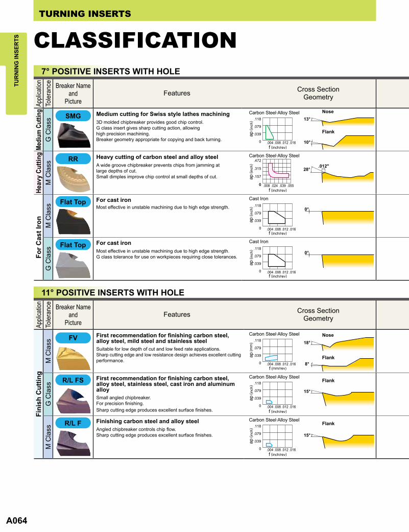
For cast ironMost effective in unstable machining due to high edge strength.G class tolerance for use on workpieces requiring close tolerances.
For cast ironMost effective in unstable machining due to high edge strength.
Heavy cutting of carbon steel and alloy steelA wide groove chipbreaker prevents chips from jamming at large depths of cut.Small dimples improve chip control at small depths of cut.
Medium cutting for Swiss style lathes machining3D molded chipbreaker provides good chip control.G class insert gives sharp cutting action, allowinghigh precision machining.Breaker geometry appropriate for copying and back turning.
Features Cross SectionGeometry
Carbon Steel·Alloy Steel
Carbon Steel·Alloy Steel
Cast Iron
Cast Iron
Flank
f (inch/rev)
f (inch/rev)
f (inch/rev)
f (inch/rev)
Nose
ap ( i
nch)
ap ( i
nch)
ap ( i
nch)
ap ( i
nch)
Medi
um C
uttin
g
11° POSITIVE INSERTS WITH HOLE
Appli
catio
nTo
lera
nce
M C
lass
G C
lass
M C
lass
Fini
sh C
uttin
g
Breaker Nameand
Picture
Finishing carbon steel and alloy steelAngled chipbreaker controls chip flow.Sharp cutting edge produces excellent surface finishes.
First recommendation for finishing carbon steel, alloy steel, stainless steel, cast iron and aluminum alloySmall angled chipbreaker.For precision finishing.Sharp cutting edge produces excellent surface finishes.
First recommendation for finishing carbon steel,alloy steel, mild steel and stainless steel Suitable for low depth of cut and low feed rate applications.Sharp cutting edge and low resistance design achieves excellent cutting performance.
Nose
Carbon Steel·Alloy Steel
Carbon Steel·Alloy Steel
Carbon Steel·Alloy Steel
Flank
Flank
Flank
f (inch/rev)
f (mm/rev)
f (inch/rev)
ap ( i
nch)
ap (m
m)
ap ( i
nch)
Features Cross SectionGeometry
A066
6°
6°
15°
15°
10°
15°
18°
8°
.008"20°8°
.008"20°8°
25°
10°
TUR
NIN
G IN
SER
TSTURNING INSERTS
CLASSIFICATION11° POSITIVE INSERTS WITH HOLE
Appli
catio
nTo
lera
nce
G C
lass
Fini
sh C
uttin
gM
Cla
ssG
Cla
ssM
Cla
ssE
Cla
ss
Breaker Nameand
Picture
Standard
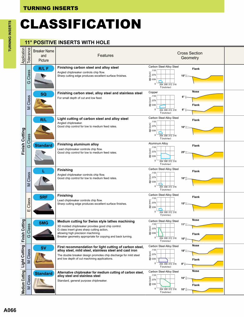
FinishingLead chipbreaker controls chip flow.Sharp cutting edge produces excellent surface finishes.
FinishingAngled chipbreaker controls chip flow.Good chip control for low to medium feed rates.
Finishing aluminum alloyLead chipbreaker controls chip flow.Good chip control for low to medium feed rates.
Light cutting of carbon steel and alloy steelAngled chipbreaker.Good chip control for low to medium feed rates.
Finishing carbon steel, alloy steel and stainless steelFor small depth of cut and low feed.
Finishing carbon steel and alloy steelAngled chipbreaker controls chip flow.Sharp cutting edge produces excellent surface finishes.
Nose
Carbon Steel·Alloy Steel
Carbon Steel·Alloy Steel
Carbon Steel·Alloy Steel
Carbon Steel·Alloy Steel
Aluminum Alloy
Copper
Flank
Flank
Flank
Flank
Flank
Flank
f (mm/rev)
f (inch/rev)
f (inch/rev)
f (inch/rev)
f (inch/rev)
f (inch/rev)
ap (m
m)
ap ( i
nch)
ap ( i
nch)
ap ( i
nch)
ap ( i
nch)
ap ( i
nch)
Features Cross SectionGeometry
Fini
sh C
uttin
gG
Cla
ss
First recommendation for light cutting of carbon steel,alloy steel, mild steel, stainless steel and cast ironThe double breaker design promotes chip discharge for mild steel and low depth of cut machining applications.
Medium cutting for Swiss style lathes machining3D molded chipbreaker provides good chip control.G class insert gives sharp cutting action, allowing high precision machining.Breaker geometry appropriate for copying and back turning.
Carbon Steel·Alloy Steel
Carbon Steel·Alloy Steel
f (inch/rev)
ap ( i
nch)
ap ( m
m)
Nose
Nose
Flank
Flank
Ligh
t Cut
ting
M C
lass
Standard Alternative chipbreaker for medium cutting of carbon steel, alloy steel and stainless steelStandard, general purpose chipbreaker.
NoseCarbon Steel·Alloy Steel
Flank
f (inch/rev)
ap ( i
nch)
Mediu
m Cu
tting
M C
lass

A068
20°
20°
25°
TUR
NIN
G IN
SER
TSTURNING INSERTS
CLASSIFICATIONTo
leran
ceAp
plicatio
nM
ediu
m C
uttin
gM
Cla
ssM
Cla
ssFo
r Cas
t Iro
nG
Cla
ss
Breaker Nameand
Picture
Flat Top
Flat Top
For cast ironMost effective in unstable machining due to high edge strength.G class tolerance allows use on workpieces requiring close tolerances.
Heavy cutting of cast ironFlat top.Most effective for unstable machining due to high edge strength.
Cast Iron
Cast Iron
f (inch/rev)
f (inch/rev)
ap ( i
nch)
ap ( i
nch)
Features Cross SectionGeometry
11° POSITIVE INSERTS WITH HOLE
15─20° POSITIVE INSERTS WITH HOLE
Applic
ation
Toler
ance
For A
lum
inum
Allo
yG
Cla
ss
Breaker Nameand
Picture
For aluminum cuttingParallel chipbreaker.Sharp cutting edge produces excellent surface finishes.
For aluminum cuttingAngled chipbreaker.Sharp cutting edge produces excellent surface finishes.
For aluminum cuttingAngled chipbreaker.Sharp cutting edge produces excellent surface finishes.
Features Cross SectionGeometry
Aluminum Alloy
Aluminum Alloy
Aluminum Alloy
Flank
Flank
Flank
f (inch/rev)
f (inch/rev)
f (inch/rev)
ap ( i
nch)
ap ( i
nch)
ap ( i
nch)
First recommendation for medium cutting of carbon steel, alloy steel, mild steel, stainless steel and cast ironA positive land and the high rake angle provides sharp cutting edge performance.Double breakers in the rake face achieve a wide range of chip control.
Carbon Steel·Alloy Steel
f (inch/rev)
ap ( i
nch)
Nose
Flank
Medium cutting of carbon steel, alloy steel and stainless steelCan be used under a wide range of cutting conditions.
NoseCopper
Flank
f (inch/rev)
ap ( i
nch)

A070
0°
0°
0°
0°
15°
0°
.012"
0°
0°
12°
TUR
NIN
G IN
SER
TSTURNING INSERTS
CLASSIFICATIONNEGATIVE INSERTS WITHOUT HOLE
Applic
ation
Toler
ance
Roug
h Cutt
ingM
Cla
ssFo
r Cas
t Iro
nM
Cla
ssG
Cla
ss
Breaker Nameand
Picture
Flat Top
Flat Top
Medium cutting of carbon steel and alloy steelSingle sided chipbreaker.Can be used for copying.An angled chipbreaker for controlling chip flow. (M1)
Heavy cutting of cast ironDouble sided flat insert.Most effective for unstable machining due to high edgestrength and stable insert clamping.
For cast ironDouble sided flat insert.Most effective for unstable machining due to high edgestrength and stable insert clamping.Use on workpieces requiring close tolerance inserts.
Features Cross SectionGeometry
Carbon Steel·Alloy Steel
Cast Iron
Cast Iron
Flank
f (inch/rev)
f (inch/rev)
f (inch/rev)
ap ( i
nch)
ap ( i
nch)
ap ( i
nch)
7° POSITIVE INSERTS WITHOUT HOLE
G C
lass
Toler
ance
For C
ast I
ron
Applic
ation Breaker Name
andPicture
Flat Top For cast ironDouble sided flat insert.Most effective for unstable machining due to high edgestrength and stable insert clamping.Use on workpieces requiring close tolerance inserts.
Features Cross SectionGeometry
Cast Iron
f (inch/rev)
ap ( i
nch)
11° POSITIVE INSERTS WITHOUT HOLE
Toler
ance
Applic
ation
Finish
Cut
ting
G C
lass
Ligh
t to
Med
ium
Cut
ting
M C
lass
For C
ast I
ron
M C
lass
G C
lass
Breaker Nameand
Picture
Flat Top
Flat Top
Standard
For cast ironFlat top.Most effective for unstable machining due to high edgestrength and stable insert clamping.Use on workpieces requiring close tolerance inserts.
Heavy cutting of cast ironFlat top.Most effective for unstable machining due to high edgestrength and stable insert clamping.
Light to medium cutting of carbon steel, alloy steel and stainless steelStandard, general purpose chipbreaker.
FinishingA parallel chipbreaker.Good chip control for low to medium feed rates.
Features Cross SectionGeometry
Cast Iron
Cast Ironf (inch/rev)
f (inch/rev)
NoseCarbon Steel·Alloy Steel
Carbon Steel·Alloy Steel
Flank
Flank
f (inch/rev)
f (inch/rev)
ap ( i
nch)
ap ( i
nch)
ap ( i
nch)
ap ( i
nch)