turning and drilling of stainless steels, optimization of ... · turning and drilling of stainless...
TRANSCRIPT
Turning and drilling of stainless steels, optimization of process
parameters
Presenter:
Co-author:
Dr. Denis Fofanov Deutsche Edelstahlwerke GmbH 1995-2001 Master degree in St. Petersburg State Polytechnical University, Russia, „Physic of metals and alloys" 2002-2006 PhD in materials science, University of Hamburg 2006 "Research and Development of stainless steels", Deutsche Edelstahlwerke GmbH
Ingrid Hofmann Deutsche Edelstahlwerke GmbH 2008 Graduating in Materials Science- and Technology at TU Bergakademie Freiberg 2008 “Continuous casting shop”, Deutsche Edelstahlwerke GmbH 2009 “Customer service stainless steels” (automotive and general industry)

Key words: stainless steel, turning, drilling, machining, cutting, land wear, cutting speed, feed rate, depth of cut
1. Abstract Modern technique is permanently evolving. New applications requiring new corrosion resistant materials appear every day. Moreover, the steel-makers always offer new steel grades which can improve the performance of already existing appliances. As a result, stainless steel components producers have to deal with the handling of new stainless steels on the everyday basis.
The final and sometimes the only stage of production of these components is often the machining. The optimal machining parameters depend not only on the equipment or the type of processing but also on the steel grade. It means that the manufacturing should be optimized for each singular grade of steel. If a new material is applied, because of e.g. better durability, strength or cheaper chemical composition, the machining process has to be optimized again. Otherwise either the component quality will be not sufficient or the production costs will be higher.
Deutsche Edelstahlwerke GmbH is constantly carrying out investigations of workability of its steel grades, in order to be able to help customers with the optimization of their production processes.
Within these experimental investigations, turning and drilling of high alloyed stainless steels (1.4307, 1.4404, 1.4511, 1.4521, 1.4362, 1.4462, 1.4021, 1.4034, 1.4057, 1.4418, 1.4542 etc.) were conducted under application of different machining parameters (cutting speed, feed rate, depth of cut, lubrication concept, tool substrate, tool coating and tool geometry). Effect of these cutting parameters on tool wear, chip shape and steel surface quality was investigated. The optimal solutions for the combination of process parameters for each investigated steel grade concerning productivity and quality were determined.
The results of these investigations relating to the machinability of selected grades are presented here together with mechanical properties and corrosion resistance of the investigated stainless steels as well as their current and prospective applications in modern technique. The results of these experimental investigations can be easily transferred to further materials and similar manufacturing processes.
Project results illustrate that the cutting of even high alloyed stainless steels is technologically feasible and economically reasonable without modifications of their chemical compositions (e.g. by adding of sulphur). Based on a detailed analysis of the processes and the adaptation of cutting parameters and cutting materials, the productivity of the conventional machining processes as a rule can be exceeded. Once the necessary adaptations of the machining parameters are made, an economic processing of high quality products is possible.
The experiments were technically and intellectually supported by company Seco Tools (cutting tool producer) and the Institute of Machining Technology of Technical University Dortmund in Germany. 2. Introduction Due to their excellent properties, stainless steels are applied in a lot of demanding applications, e.g. in automotive industry, chemical industry, mechanical engineering, offshore technique, medicine, food industry etc. [1, 2, 3]. Depending on their chemical composition, stainless steels can be divided into different groups: Austenitic steels, like e.g. 1.4307 and 1.4404, possess a high corrosion resistance in natural (urban and rural) surroundings with low chloride contents. They are also characterized by their non-magnetization and good processing properties. Forging, welding, cold working and polishing are possible without significant problems. To their properties belong also low thermal conductivity (~15 W/m·K), high thermal expansion coefficient, high ductility and the tendency to cold work hardening. Ferritic steels, such as 1.4511 or 1.4521, show good corrosion resistance, especially against stress corrosion cracking and relatively low hardness. Contrary to austenitic steels, ferritic grades are characterized by their high thermal conductivity (~25 W/m·K). On the other hand, their weldability is challenging. There is the danger of coarsening and embrittlement. That is why too high temperatures and long heating periods during welding should be avoided. Martensitic steels show high strength and hardness caused by their high carbon content. They also have the tendency to cold work

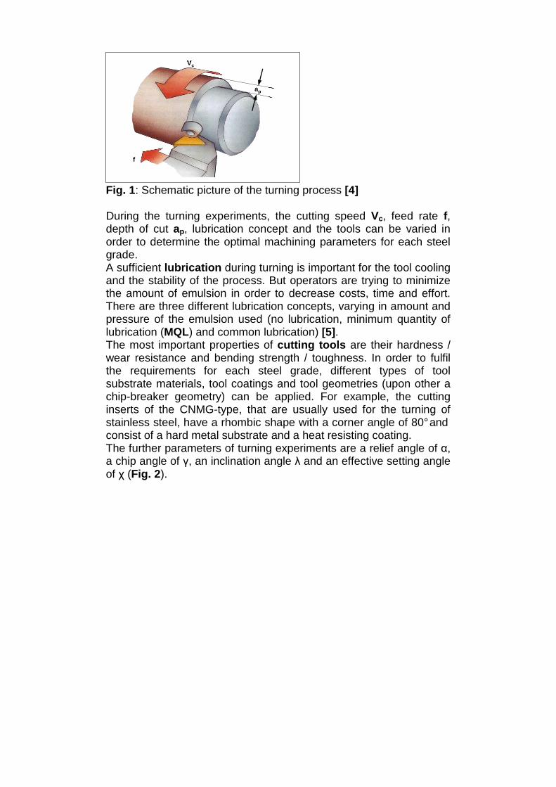
hardening. As well as ferritic steels, martensitic ones are characterized by high thermal conductivity (~30 W/m·K). Nickel-martensites like 1.4418 are characterized by high strength and high ductility. They also show good resistance against intergranular corrosion and stress corrosion cracking. They have low thermal conductivity (~15 W/m·K) and high hardness. Precipitation hardening steels like 1.4542 are widely used because of their high corrosion resistance, high wear resistance and good mechanical properties. By precipitation hardening, different levels in hardness and yield strength can be adjusted with special heat treatments. Their thermal conductivity is relatively low (~16 W/m·K). Duplex steels like 1.4462 are characterized by a ferritic-austenitic structure. These grades show excellent corrosion resistance and mechanical properties which are suitable for a wide range of applications. They own the combination of high strength and ductility at the same time and low thermal conductivity (~15 W/m·K). The final step in the production of stainless steel components is often the machining. Unfortunately, the machining behaviour of some grades can be very challenging. Since every steel grade can show different machining behaviour, it is very important to know about the characteristics of each grade and to choose the right machining parameters for it. The aim of the following experiments was to find the optimal parameters for turning and drilling of some common stainless steel grades and to compare the machining behaviour of the different steel groups. 2.1 Principles of Machining The term “machining“ summarizes all mechanical operations, in which a component is brought to its desired shape by removing redundant material in form of chips. This can include processes like turning, drilling, milling, grinding, planing, filing etc. 2.1.1 Turning Turning (Fig. 1) is a machining operation, where the cutting edge of a tool is brought against the surface of a rotating workpiece in order to remove parts of the surface in form of chips. The cutting tool can be moved along two axes of motion to produce precise diameters and various geometries.
ap
Vc
f
ap
Vc
f
ap
Vc
f
Fig. 1: Schematic picture of the turning process [4] During the turning experiments, the cutting speed Vc, feed rate f, depth of cut ap, lubrication concept and the tools can be varied in order to determine the optimal machining parameters for each steel grade. A sufficient lubrication during turning is important for the tool cooling and the stability of the process. But operators are trying to minimize the amount of emulsion in order to decrease costs, time and effort. There are three different lubrication concepts, varying in amount and pressure of the emulsion used (no lubrication, minimum quantity of lubrication (MQL) and common lubrication) [5]. The most important properties of cutting tools are their hardness / wear resistance and bending strength / toughness. In order to fulfil the requirements for each steel grade, different types of tool substrate materials, tool coatings and tool geometries (upon other a chip-breaker geometry) can be applied. For example, the cutting inserts of the CNMG-type, that are usually used for the turning of stainless steel, have a rhombic shape with a corner angle of 80° and consist of a hard metal substrate and a heat resisting coating. The further parameters of turning experiments are a relief angle of α, a chip angle of γ, an inclination angle λ and an effective setting angle of χ (Fig. 2).

Fig. 2: Schematic picture of the cutting process (Courtesy of ISF) Other important characteristics are cutting force components, such as the cutting force Fc, the feed force Ff and the passive force Fp (Fig. 3).
Fig. 3: Schematic picture of the cutting force components during turning (right) and drilling (left) (Fa active force, Vc cutting speed, Ve effective cutting speed, Vf feed rate) [6]

To evaluate the productivity and the quality of the machining process the processing time th, tool flank wear VBmax, surface quality (roughness Rz), chip shape and burr formation should be considered. Tool wear occurs because of mechanical, thermal and chemical impact. During machining the tool can show abrasive or adhesive wear, cracks, oxidation or it can even break. The tool wear can be characterized by flank and crater wear. The chip shape varies depending on the steel grade and the machining parameters. For a safe and reliable machining process, short easy removable chips are preferred. Unfavourable are long, lamellar and twisted chips, wrapping around the workpiece and machine parts. 2.1.2 Drilling Drilling is a manufacturing process where a rotating tool is used to cut a hole into a workpiece (Fig. 3). Drilling speed Vc, feed rate f, drill types and lubrication concepts are the parameters that can effect the drilling process and the workpiece quality. The drilling process can be characterized by the chip shape, cutting forces and tool wear as well as the diameter, circularity and surface quality of the boring. The biggest challenge during drilling is the chip removal. The accumulation of chips in the hole affects the surface quality and can cause tool breakages. 3. Experimental Following grades are being investigated: 1.4307 (UNS S 30403), 1.4571 (UNS S 31635), 1.4404 (UNS S 31603), 1.4511, 1.4521 (UNS S 44400), 1.4362 (UNS S 32304), 1.4462 (UNS S 31803), 1.4021 (UNS S 42000), 1.4034, 1.4057 (UNS S 43100), 1.4418, 1.4542 (UNS S 17400) etc. The machinability tests were carried out in the Ugitech Research Centre in France (Ugine) and in ISF (Institut für Spanende Fertigung, TU Dortmund) with supporting of Seco Tools. Turning machines: lathe RAMO RTN30 (Ugine), CNC-lathe Monforts RNC 200 (ISF) Drilling machines: ALZMETALL BAZ 15 CNC (Ugine), Grob BZ 40 CS (ISF)

For all turning experiments, the holding device for the cutting tools was a cartridge of the DCLNL2525M12KC04 type with a relief angle of α = 5°, a chip angle of γ = -5°, an inclination angle λ = -5° and an effective setting angle of χ = 95° ( Fig. 2). The cutting force components (Fc, Ff and Fp) have been recorded continuously with a 3-channel dynamometer (type 9121, Kistler). 4. Results and discussion 4.1 Austenitic stainless steels 4.1.1 State of technique The main part of world wide stainless steel consumption is covered by austenitic stainless steels. The reason is their good corrosion resistance, high toughness at low temperatures, good formability and weldability.
Concerning the machining, austenitic stainless steels are more sophisticated than common carbon steels. They are very prone to work hardening during cold working, including all types of machining. For instance the work hardening coefficient of 1.4305 is 3 - 5 times higher than that of common low carbon automatic steel [7]. An example of work hardening behaviour for 1.4307 and 1.4404 can be seen in Fig. 4.
1700
1400
1150
1100
1000
900
0
85
72
57
43
28
14
00 20 40 60 80 100 120
Deformation [%]
Ten
sile
stre
ngth
[MP
a]
Elo
ngat
ion
[%]
1.4307
Rm
Rp
A
drawn in 7 passes from Ø 7,60 to Ø 4,01 mm
1700
1400
1150
1100
1000
900
0
85
72
57
43
28
14
00 20 40 60 80 100 120
Deformation [%]
Ten
sile
stre
ngth
[MP
a]
Nec
king
[%]
1.4404
Rm
Rp
Z
drawn in 7 passes from Ø 7,60 to Ø 4,01 mm
1700
1400
1150
1100
1000
900
0
85
72
57
43
28
14
00 20 40 60 80 100 120
Deformation [%]
Ten
sile
stre
ngth
[MP
a]
Elo
ngat
ion
[%]
1.4307
Rm
Rp
A
drawn in 7 passes from Ø 7,60 to Ø 4,01 mm
1700
1400
1150
1100
1000
900
0
85
72
57
43
28
14
00 20 40 60 80 100 120
Deformation [%]
Ten
sile
stre
ngth
[MP
a]
Elo
ngat
ion
[%]
1.4307
Rm
Rp
A
drawn in 7 passes from Ø 7,60 to Ø 4,01 mm
1700
1400
1150
1100
1000
900
0
85
72
57
43
28
14
00 20 40 60 80 100 120
Deformation [%]
Ten
sile
stre
ngth
[MP
a]
Nec
king
[%]
1.4404
Rm
Rp
Z
drawn in 7 passes from Ø 7,60 to Ø 4,01 mm
1700
1400
1150
1100
1000
900
0
85
72
57
43
28
14
00 20 40 60 80 100 120
Deformation [%]
Ten
sile
stre
ngth
[MP
a]
Nec
king
[%]
1.4404
Rm
Rp
Z
drawn in 7 passes from Ø 7,60 to Ø 4,01 mm
Fig. 4: Effect of the cold deformation on the mechanical properties of 1.4307 (left) and 1.4404 (right)
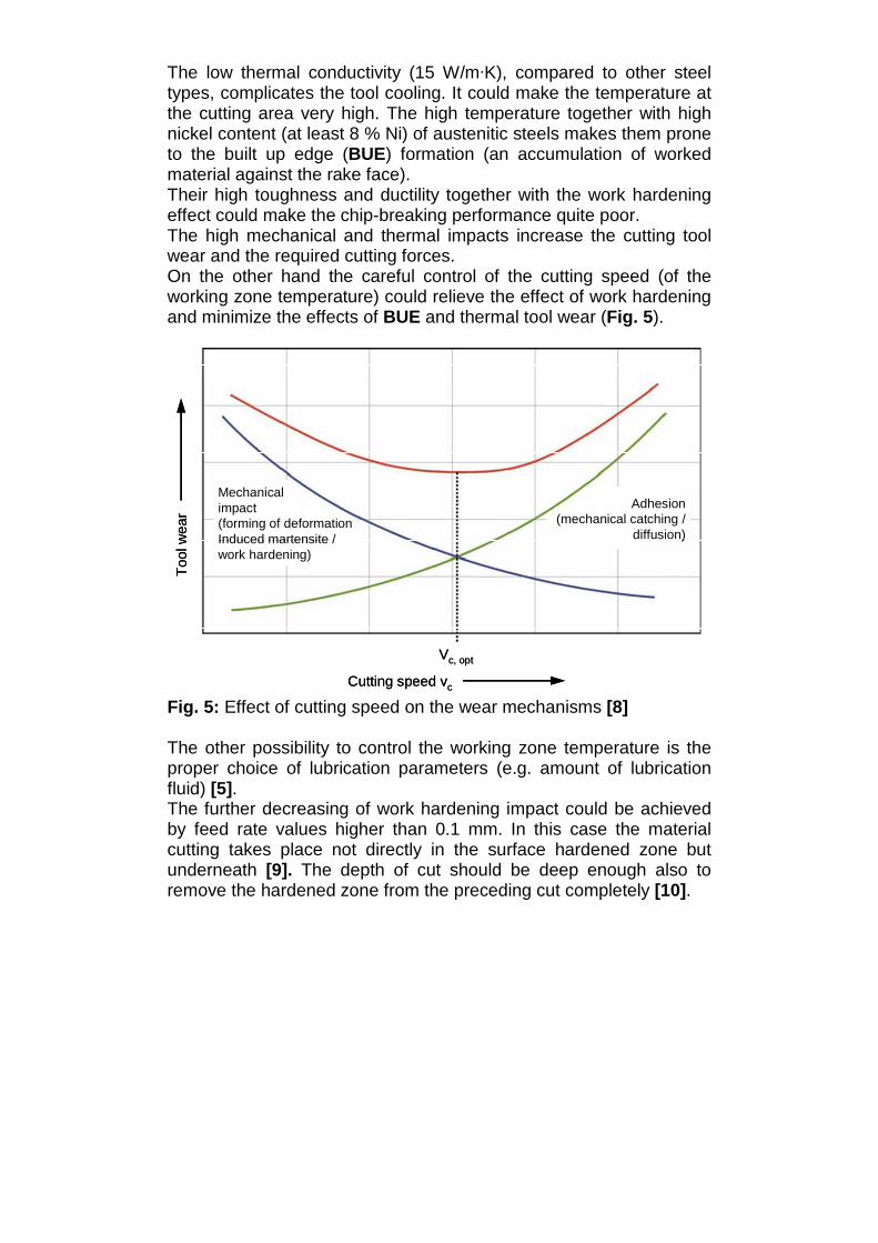
The low thermal conductivity (15 W/m·K), compared to other steel types, complicates the tool cooling. It could make the temperature at the cutting area very high. The high temperature together with high nickel content (at least 8 % Ni) of austenitic steels makes them prone to the built up edge (BUE) formation (an accumulation of worked material against the rake face). Their high toughness and ductility together with the work hardening effect could make the chip-breaking performance quite poor. The high mechanical and thermal impacts increase the cutting tool wear and the required cutting forces. On the other hand the careful control of the cutting speed (of the working zone temperature) could relieve the effect of work hardening and minimize the effects of BUE and thermal tool wear (Fig. 5).
Cutting speed vc
Too
l wea
r
Vc, opt
Mechanicalimpact(forming of deformationInduced martensite /work hardening)
Adhesion(mechanical catching /
diffusion)
Cutting speed vc
Too
l wea
r
Vc, opt
Mechanicalimpact(forming of deformationInduced martensite /work hardening)
Adhesion(mechanical catching /
diffusion)
Fig. 5: Effect of cutting speed on the wear mechanisms [8] The other possibility to control the working zone temperature is the proper choice of lubrication parameters (e.g. amount of lubrication fluid) [5]. The further decreasing of work hardening impact could be achieved by feed rate values higher than 0.1 mm. In this case the material cutting takes place not directly in the surface hardened zone but underneath [9]. The depth of cut should be deep enough also to remove the hardened zone from the preceding cut completely [10].
The chip length and shape can be optimized varying the feed rate and the depth of cut as well [11]. The other way to do it is the proper choice of cutting tool geometry (chip-breaker geometry) [12]. These ways can be applied either separately or simultaneously. In the second case even further enhancement of chip geometry is possible. The further optimization of cutting processes can be achieved by appropriate material selection for the cutting tool and coating [5, 12 and 13]. To sum up, the austenitic stainless steels can be machined efficiently with the proper choice of cutting and lubrication parameters (e.g. cutting speed; feed rate and depth of cut; material, coating and geometry of cutting tool; pressure and amount of lubrication fluid) [5, 7, 12, 13, 14]. 4.1.2 Turning of austenitic stainless steels 1.4307 is one of the most popular austenitic stainless steels (and stainless steels at all). In the first part of the experiments the cutting speed (Vc) was varied from 230 to 300 m/min with constant feed rate (f = 0.25 mm) and depth of cut (ap = 1.5 mm). The experiments were carried out without lubrication, in Ugine. The applied tool was SECO TM2000 CNMG 120408-MF4. The maximal possible Vc, whereby in 15 min the flank wear of 0.15 mm was reached, was 260 m/min.
For the second part of the experiments f was varied from 0.1 to 0.4 mm, ap from 0.5 to 4 mm, Vc = 200 m/min. The purpose was to investigate the effect of f and ap on the chip shape. In the blue zone chips are short and there is no risk for the turning operation (Fig. 6). But for some conditions (high ap > 3.5 mm and high f > 0.25 mm/rev), the surface quality may be limited and the stress levels can be too high.

Fig. 6: Effect of the feed rate and depth of cut on the chip shape In order to investigate the effect of the machining time on the chip shape, surface quality and burr formation the experiment was repeated with lubrication (ISF, GC2025 CNMG 120408-MF, Vc = 250 m/min, ap = 1 and f = 0.25 mm). The chip shape assures their easy removing. Moderate burr formation (Fig. 7) and surface roughness (Rz = 11.1 µm) at the beginning and at the end of the machining time were achieved.

t h=
15 m
int h
= 2
min
Cutting speed: vc = 250 m/min Steel: 1.4307Feed rate: f = 0.25 mm Lubrication: EmulsionDepth of cut: ap = 1 mm Cutting time: th = 2…15 minTool: GC2025 CNMG120408-MF
t h=
15 m
int h
= 2
min
Cutting speed: vc = 250 m/min Steel: 1.4307Feed rate: f = 0.25 mm Lubrication: EmulsionDepth of cut: ap = 1 mm Cutting time: th = 2…15 minTool: GC2025 CNMG120408-MF
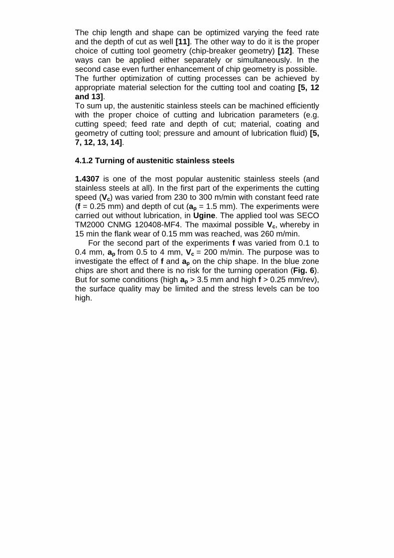
Fig. 7: Effect of the cutting time on the chip shape and the burr formation during the turning of 1.4307 Summarized, the maximal possible cutting speed for the turning of 1.4307 without emulsion is about 260 m/min. The combination of ap and f for an optimal chip shape were determined (Fig. 6), ap between 1 and 3.5 mm and f between 0.2 and 0.3 mm can be used. 1.4404 is the austenitic stainless steel with higher corrosion resistance than 1.4307. At first the effect of cutting speed on the flank wear during the machining of 1.4404 was investigated (ISF, TN7015 CNMG 120408-AP, ap = 2.5 mm and f = 0.2 mm, without emulsion). The lowest flank wear was measured for the speed 150 m/min (Fig. 8); the reason can be the already mentioned effect of stress relieving (Fig. 5). Further speed increasing led to higher tool wear because of exceeding the tools heat-resistance. The lower optimal value of cutting speed than for 1.4307 can be explained by higher tensile strength of 1.4404 [15].
0,15
0,23
0,30
0,38
0,45
0,53
0,60
75 100 125 150 175 200 225Vc, m/min
VB
max
, mm
Fig. 8: Effect of the cutting speed on the flank wear during the dry turning of 1.4404 Concerning the cutting strengths and chip form, different combinations of feed rate and depth of cut were tested; the values of feed rate between 0.15 and 0.40 mm and of depth of cut between 1.0 and 2.5 mm can be applied. The further decreasing of flank wear and surface roughness is possible through the optimization of lubrication process. The applying of MQL results in lower flank wear and surface roughness than either in the case of common lubrication or the case of dry machining (without lubrication) [15]. Besides the feed rate, the depth of cut and lubrication concept the chip-breaker geometry is very important for the chip form. The effect of different chip-breaker geometries on the chip shape is illustrated in Fig. 9.

MF4Chip-breaker
MR3MF1
Cutting speed: vc = 150 m/min Steel: 1.4404Feed rate: f = 0.4 mm Lubrication: EmulsionDepth of cut: ap = 1 mm Cutting time: th = 1 minTool: CP500 CNMG 120408, Chip-breaker varied
MF4Chip-breaker
MR3MF1
Cutting speed: vc = 150 m/min Steel: 1.4404Feed rate: f = 0.4 mm Lubrication: EmulsionDepth of cut: ap = 1 mm Cutting time: th = 1 minTool: CP500 CNMG 120408, Chip-breaker varied
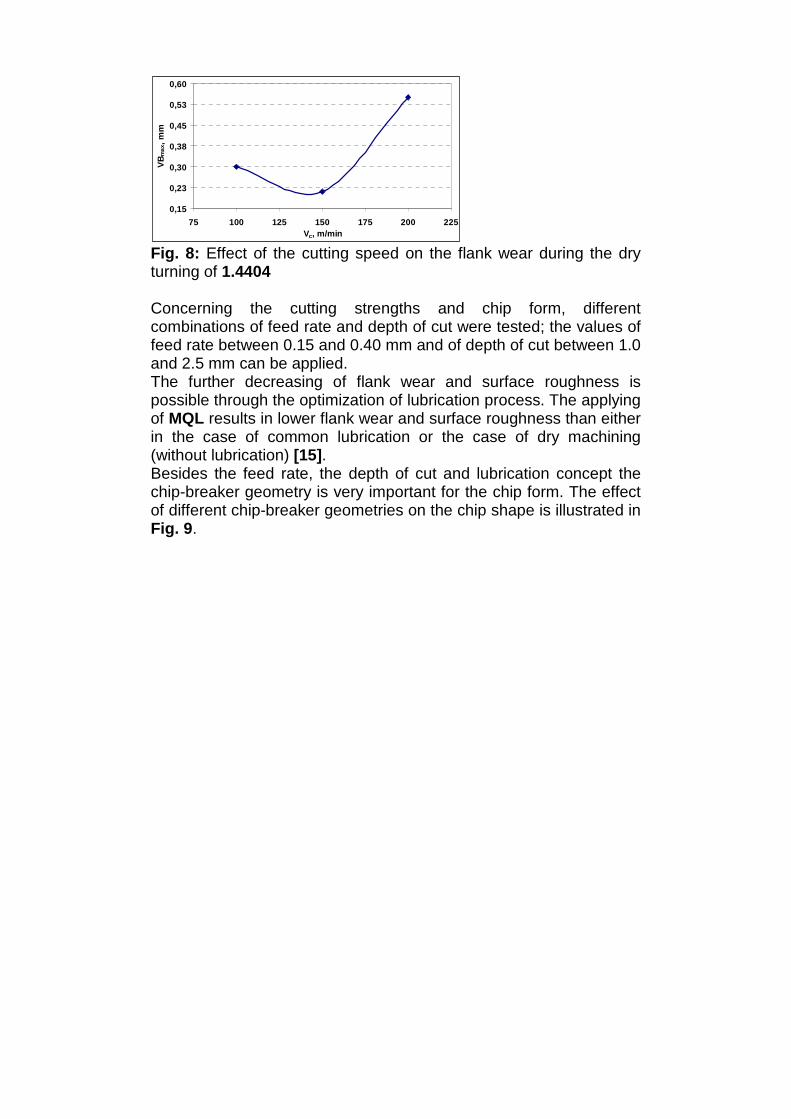
Fig. 9: Effect of the chip-breaker geometry on the chip form during the turning of 1.4404 To sum up, the optimal cutting speed for the turning of 1.4404 is between 150 and 200 m/min. The combination of ap and f for an optimal chip shape were determined: ap between 1 and 2.5 mm and f between 0.15 and 0.40 mm can be used. 1.4571: This steel has, in principle, same chemical composition as 1.4404 but is stabilized with titanium. As experiments showed, it can be turned under the same conditions as 1.4404. Because of a little bit lower tensile strength the applied cutting speed can be even higher than that of 1.4404 (between 160 and 220 m/min). The existing titanium carbonitrides cause the formation of shorter chips than that of 1.4404 (Fig. 10).
Cutting speed: vc = 250 m/min Steel: 1.4404 and 1.4571Feed rate: f = 0.25 mm Lubrication: EmulsionDepth of cut: ap = 1 mm Cutting time: th = 2 minTool: GC2025 CNMG120408-MF
1.4404 1.4571
Cutting speed: vc = 250 m/min Steel: 1.4404 and 1.4571Feed rate: f = 0.25 mm Lubrication: EmulsionDepth of cut: ap = 1 mm Cutting time: th = 2 minTool: GC2025 CNMG120408-MF
1.4404 1.4571
Fig. 10: Comparison of chip form of 1.4404 and 1.4571 4.1.3 Drilling of austenitic stainless steels
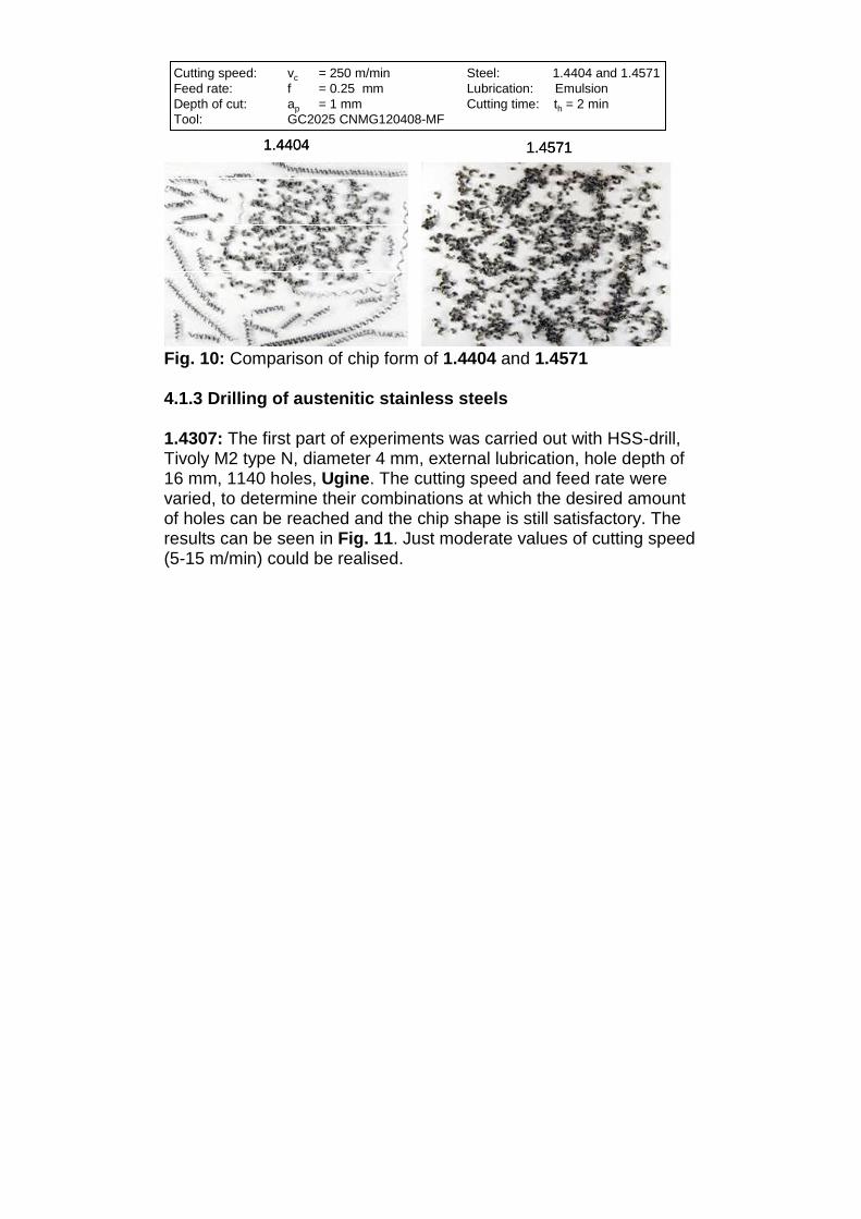
1.4307: The first part of experiments was carried out with HSS-drill, Tivoly M2 type N, diameter 4 mm, external lubrication, hole depth of 16 mm, 1140 holes, Ugine. The cutting speed and feed rate were varied, to determine their combinations at which the desired amount of holes can be reached and the chip shape is still satisfactory. The results can be seen in Fig. 11. Just moderate values of cutting speed (5-15 m/min) could be realised.
Fig. 11: Effect of the feed rate and cutting speed on the achieved number of holes The experiment was repeated with an insert-drill, DK 460 UF-S-TiN-RT100F, diameter 6 mm, internal lubrication, hole depth of 24 mm, 516 holes. The results can be seen in Fig. 12. The achievable cutting speed was significantly higher (40-120 m/min) than in the case of HSS-drills.
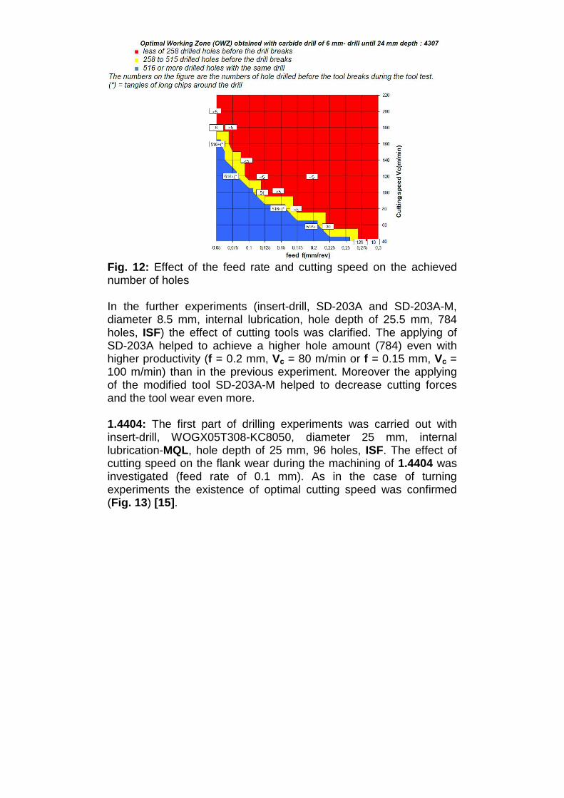
Fig. 12: Effect of the feed rate and cutting speed on the achieved number of holes In the further experiments (insert-drill, SD-203A and SD-203A-M, diameter 8.5 mm, internal lubrication, hole depth of 25.5 mm, 784 holes, ISF) the effect of cutting tools was clarified. The applying of SD-203A helped to achieve a higher hole amount (784) even with higher productivity (f = 0.2 mm, Vc = 80 m/min or f = 0.15 mm, Vc = 100 m/min) than in the previous experiment. Moreover the applying of the modified tool SD-203A-M helped to decrease cutting forces and the tool wear even more. 1.4404: The first part of drilling experiments was carried out with insert-drill, WOGX05T308-KC8050, diameter 25 mm, internal lubrication-MQL, hole depth of 25 mm, 96 holes, ISF. The effect of cutting speed on the flank wear during the machining of 1.4404 was investigated (feed rate of 0.1 mm). As in the case of turning experiments the existence of optimal cutting speed was confirmed (Fig. 13) [15].

0,15
0,20
0,25
0,30
0,35
0,40
0,45
125 150 175 200 225 250 275Vc, m/min
VB
max
, mm
Fig. 13: Effect of the cutting speed on the flank wear during the drilling of 1.4404 During the further experiments (f = 0.1 mm, Vc = 200 m/min) the effect of lubrication concept was clarified. The applying of MQL was not really advantageous concerning the tool wear, the chip removal and the surface quality. The better results could be achieved with the common lubrication, where the excess of emulsion supports the chip removal [15]. Two different emulsion pressures (25 and 60 bar) were tested with insert-drill SD-203A and SD-203A-M, diameter 8.5 mm, internal lubrication, hole depth of 25.5 mm, 784 holes. The higher pressure proved to be more beneficial, especially regarding the chip removal. The optimal conditions in this experiment were feed rate of 0.2 mm and cutting speed of 80 m/min. Once again the applying of modified tool SD-203A-M helped to decrease the cutting forces and tool wear. 4.2 Ferritic stainless steels 4.2.1 State of technique Because of high nickel prices, ferritic stainless steels are more reasonably priced than austenitic steels with a similar corrosion resistance. Additionally, contrary to austenitic steels, they are more resistant to stress-corrosion cracking. The machinability of ferritic stainless steels is usually considered to be comparable with that of common carbon steels with the same hardness [9]. The usually low hardness, strengths and high thermal conductivity (25 W/m·K), compared to other stainless steel types, cause as a rule the moderate tool wear. On the other hand, low strength can cause the formation of burr, ribbon and thread chips. Prior cold work hardening reduces this tendency.

Furthermore ferritic steels are prone to BUE-formation. To avoid that, the cutting speed should be higher than 100 m/min [5]. Generally the cutting speed can be up to 30 % and the feed rate up to 25 % higher than that of austenitic stainless steels [10]. 4.2.2 Turning of ferritic stainless steels The turning experiments were carried out for 1.4511 and 1.4521 with the cutting speed 250 m/min, the feed rate 0.25 mm, the depth of cut 1 mm, lubrication and the tool GC2025 CNMG 120408-MF. The literature data were generally confirmed. Moderate tool wear and cutting forces as well as almost no effect of work hardening during machining were observed. The chip form and burr formation were not optimal but acceptable (Fig. 14).
Cutting speed: vc = 250 m/min Steel: 1.4511 and 1.4521Feed rate: f = 0.25 mm Lubrication: EmulsionDepth of cut: ap = 1 mm Cutting time: th = 15 minTool: GC2025 CNMG120408-MF
1.4511 1.4521
Cutting speed: vc = 250 m/min Steel: 1.4511 and 1.4521Feed rate: f = 0.25 mm Lubrication: EmulsionDepth of cut: ap = 1 mm Cutting time: th = 15 minTool: GC2025 CNMG120408-MF
1.4511 1.4521
Fig. 14: Chip form and burr formation of 1.4511 (left) and 1.4521 (right)
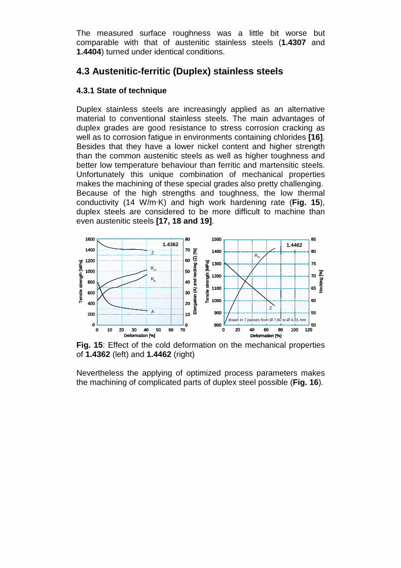
The measured surface roughness was a little bit worse but comparable with that of austenitic stainless steels (1.4307 and 1.4404) turned under identical conditions. 4.3 Austenitic-ferritic (Duplex) stainless steels 4.3.1 State of technique Duplex stainless steels are increasingly applied as an alternative material to conventional stainless steels. The main advantages of duplex grades are good resistance to stress corrosion cracking as well as to corrosion fatigue in environments containing chlorides [16]. Besides that they have a lower nickel content and higher strength than the common austenitic steels as well as higher toughness and better low temperature behaviour than ferritic and martensitic steels. Unfortunately this unique combination of mechanical properties makes the machining of these special grades also pretty challenging. Because of the high strengths and toughness, the low thermal conductivity (14 W/m·K) and high work hardening rate (Fig. 15), duplex steels are considered to be more difficult to machine than even austenitic steels [17, 18 and 19].
1500
1400
1300
1200
1100
1000
800
85
80
75
70
65
60
500 20 40 60 80 100 120
Deformation [%]
Ten
sile
stre
ngth
[MP
a]
Nec
king
[%]
1.4462
Rm
Z
drawn in 7 passes from Ø 7,60 to Ø 4,01 mm
900 55
1600
1400
1200
800
600
200
Ten
sile
stre
ngth
[MP
a]
400
0
1000Rm
Z
Rp
A
1.436280
70
60
50
40
30
70
Elo
ngat
ion
(A)
and
neck
ing
(Z)
[%]
20
10
00 10 20 30 40 50
Deformation [%]60
1500
1400
1300
1200
1100
1000
800
85
80
75
70
65
60
500 20 40 60 80 100 120
Deformation [%]
Ten
sile
stre
ngth
[MP
a]
Nec
king
[%]
1.4462
Rm
Z
drawn in 7 passes from Ø 7,60 to Ø 4,01 mm
900 55
1500
1400
1300
1200
1100
1000
800
85
80
75
70
65
60
500 20 40 60 80 100 120
Deformation [%]
Ten
sile
stre
ngth
[MP
a]
Nec
king
[%]
1.4462
Rm
Z
drawn in 7 passes from Ø 7,60 to Ø 4,01 mm
900 55
1600
1400
1200
800
600
200
Ten
sile
stre
ngth
[MP
a]
400
0
1000Rm
Z
Rp
A
1.436280
70
60
50
40
30
70
Elo
ngat
ion
(A)
and
neck
ing
(Z)
[%]
20
10
00 10 20 30 40 50
Deformation [%]60
1600
1400
1200
800
600
200
Ten
sile
stre
ngth
[MP
a]
400
0
1000Rm
Z
Rp
A
1.436280
70
60
50
40
30
70
Elo
ngat
ion
(A)
and
neck
ing
(Z)
[%]
20
10
00 10 20 30 40 50
Deformation [%]60
Fig. 15: Effect of the cold deformation on the mechanical properties of 1.4362 (left) and 1.4462 (right) Nevertheless the applying of optimized process parameters makes the machining of complicated parts of duplex steel possible (Fig. 16).

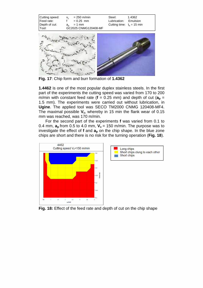
Fig. 16: Cutting blade for tap fittings made of 1.4462 4.3.2 Turning of Austenitic-ferritic (Duplex) stainless steels 1.4362 was turned with the cutting speed 250 m/min, the feed rate 0.25 mm, the depth of cut 1 mm, lubrication and the tool GC2025 CNMG 120408-MF at ISF. The observed tool wear and cutting forces were comparable or even smaller than these of the austenitic stainless steels (1.4307, 1.4404 and 1.4571) machined under the same conditions. The chip form (Fig. 17) was comparable to that of ferritic stainless steels (Fig. 14) cut under identical conditions. The surface quality and burr formation (Fig. 17) were even better than that either of ferritic (Fig. 14) or austenitic steels (Fig. 7).
Cutting speed: vc = 250 m/min Steel: 1.4362Feed rate: f = 0.25 mm Lubrication: EmulsionDepth of cut: ap = 1 mm Cutting time: th = 15 minTool: GC2025 CNMG120408-MF
Cutting speed: vc = 250 m/min Steel: 1.4362Feed rate: f = 0.25 mm Lubrication: EmulsionDepth of cut: ap = 1 mm Cutting time: th = 15 minTool: GC2025 CNMG120408-MF
Fig. 17: Chip form and burr formation of 1.4362 1.4462 is one of the most popular duplex stainless steels. In the first part of the experiments the cutting speed was varied from 170 to 200 m/min with constant feed rate (f = 0.25 mm) and depth of cut (ap = 1.5 mm). The experiments were carried out without lubrication, in Ugine. The applied tool was SECO TM2000 CNMG 120408-MF4. The maximal possible Vc, whereby in 15 min the flank wear of 0.15 mm was reached, was 170 m/min.
For the second part of the experiments f was varied from 0.1 to 0.4 mm, ap from 0.5 to 4.0 mm, Vc = 150 m/min. The purpose was to investigate the effect of f and ap on the chip shape. In the blue zone chips are short and there is no risk for the turning operation (Fig. 18).
Fig. 18: Effect of the feed rate and depth of cut on the chip shape

During the further experiments (ISF, TN8025 CNMG 120408-AP, Vc = 100 m/min, ap = 2.5 mm and f = 0.15 mm) the effect of the lubrication concept was clarified. Neither the machining without lubrication nor the applying of MQL was advantageous concerning tool wear, chip removal and surface quality. The better results could be achieved with the common lubrication [15]. Then the effect of cutting speed on the tool wear and surface quality with applied emulsion was investigated. The Vc was varied between 100 and 250 m/min with f = 0.3 mm, ap = 1.5 mm, SECO TM4000 CNMG 120408-MF4. From both points of view (tool wear and surface quality) the cutting speed of 150 m/min was the most beneficial one. To sum up, the optimal cutting speed for turning 1.4462 is between 130 and 170 m/min. The combination of ap and f for an optimal chip shape were determined, ap between 1 and 2.5 mm and f between 0.3 and 0.4 mm can be used. The lubrication concept with emulsion should be used. 4.3.3 Drilling of Austenitic-ferritic (Duplex) stainless steels The first part of drilling experiments on 1.4462 was carried out with HSS-drill, Tivoly M2 type N, diameter 4 mm, external lubrication, hole depth of 16 mm, 1140 holes, Ugine. The cutting speed and feed rate were varied, to determine their combinations at which the drilling way can be reached and the chip shape is still satisfactory. Only a few conditions near the cutting speed of 10 m/min and feed rate of 0.125 could be recommended. The experiment was repeated with insert-drill, DK 460 UF-S-TiN-RT100F, diameter 6 mm, internal lubrication, hole depth of 24 mm, 516 holes. The results can be seen in Fig. 19. The achievable cutting speed was significantly higher than that in the case of HSS-drills.

Fig. 19: Effect of the feed rate and cutting speed on the achieved number of holes The third part of drilling experiments was carried out with insert-drill, WOGX05T308-KC8050, diameter 25 mm, internal lubrication-MQL, hole depth of 25 mm, 16 holes, ISF. The effect of cutting speed on the flank wear during the machining of 1.4462 was investigated (feed rate between 0.05 and 0.10 mm). Similar to drilling experiments with 1.4404 the existence of optimal cutting speed concerning the tool wear and the surface quality was confirmed (Vc opt ≈ 200 m/min). The effect of the lubrication concept was clarified in the following experiments. Like the turning experiments the best results were achieved for the drilling with emulsion [15]. 4.4 Martensitic stainless steels 4.4.1 State of technique Martensitic stainless steels are characterised by high hardness and strengths in conjunction with good corrosion resistance in moderately corrosive environments. They are used in the quenched and tempered condition and because of their mechanical properties, they are ideally suited for the high strength applications like cutting tools, roller bearings etc. The machinability of martensitic stainless steels is usually considered to be comparable with that of common carbon steels with the same hardness [9]. The high hardness and tensile strength could cause a
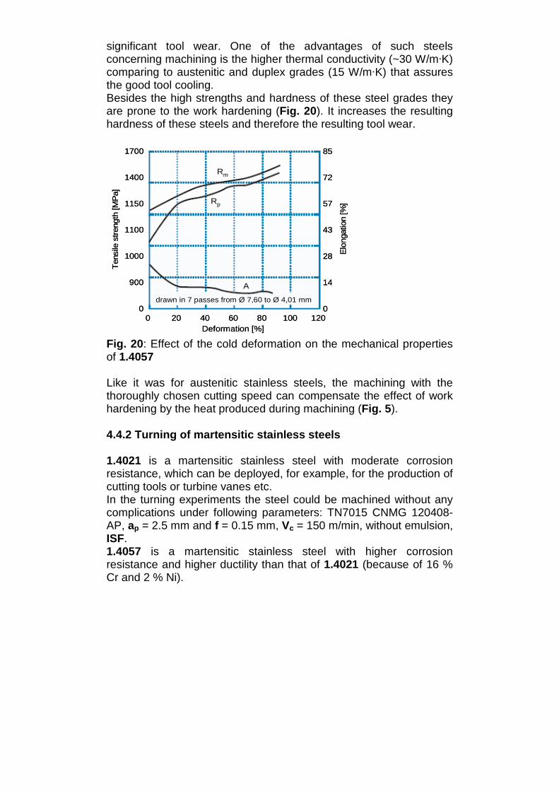
significant tool wear. One of the advantages of such steels concerning machining is the higher thermal conductivity (~30 W/m·K) comparing to austenitic and duplex grades (15 W/m·K) that assures the good tool cooling. Besides the high strengths and hardness of these steel grades they are prone to the work hardening (Fig. 20). It increases the resulting hardness of these steels and therefore the resulting tool wear.
1700
1400
1150
1100
1000
900
0
85
72
57
43
28
14
00 20 40 60 80 100 120
Deformation [%]
Ten
sile
stre
ngth
[MP
a]
Elo
ngat
ion
[%]
Rm
Rp
A
drawn in 7 passes from Ø 7,60 to Ø 4,01 mm
1700
1400
1150
1100
1000
900
0
85
72
57
43
28
14
00 20 40 60 80 100 120
Deformation [%]
Ten
sile
stre
ngth
[MP
a]
Elo
ngat
ion
[%]
Rm
Rp
A
drawn in 7 passes from Ø 7,60 to Ø 4,01 mm
Fig. 20: Effect of the cold deformation on the mechanical properties of 1.4057 Like it was for austenitic stainless steels, the machining with the thoroughly chosen cutting speed can compensate the effect of work hardening by the heat produced during machining (Fig. 5). 4.4.2 Turning of martensitic stainless steels 1.4021 is a martensitic stainless steel with moderate corrosion resistance, which can be deployed, for example, for the production of cutting tools or turbine vanes etc. In the turning experiments the steel could be machined without any complications under following parameters: TN7015 CNMG 120408-AP, ap = 2.5 mm and f = 0.15 mm, Vc = 150 m/min, without emulsion, ISF. 1.4057 is a martensitic stainless steel with higher corrosion resistance and higher ductility than that of 1.4021 (because of 16 % Cr and 2 % Ni).
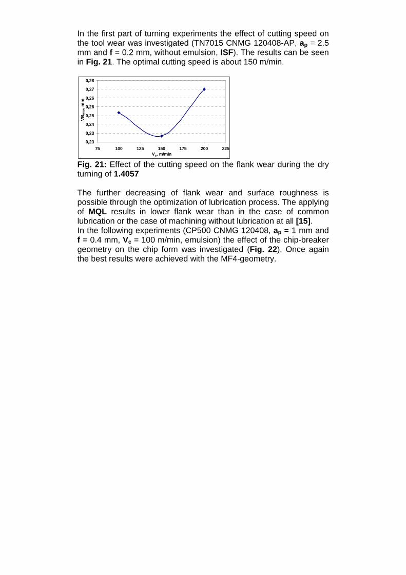
In the first part of turning experiments the effect of cutting speed on the tool wear was investigated (TN7015 CNMG 120408-AP, ap = 2.5 mm and f = 0.2 mm, without emulsion, ISF). The results can be seen in Fig. 21. The optimal cutting speed is about 150 m/min.
0,23
0,23
0,24
0,25
0,26
0,26
0,27
0,28
75 100 125 150 175 200 225Vc, m/min
VB
max
, mm
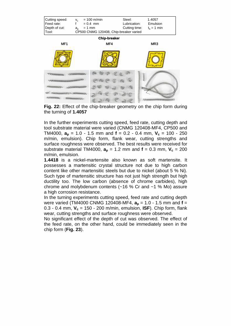
Fig. 21: Effect of the cutting speed on the flank wear during the dry turning of 1.4057 The further decreasing of flank wear and surface roughness is possible through the optimization of lubrication process. The applying of MQL results in lower flank wear than in the case of common lubrication or the case of machining without lubrication at all [15]. In the following experiments (CP500 CNMG 120408, ap = 1 mm and f = 0.4 mm, Vc = 100 m/min, emulsion) the effect of the chip-breaker geometry on the chip form was investigated (Fig. 22). Once again the best results were achieved with the MF4-geometry.
MF4
Chip-breaker
MR3MF1
Cutting speed: vc = 100 m/min Steel: 1.4057Feed rate: f = 0.4 mm Lubrication: EmulsionDepth of cut: ap = 1 mm Cutting time: th = 1 minTool: CP500 CNMG 120408, Chip-breaker varied
MF4
Chip-breaker
MR3MF1
Cutting speed: vc = 100 m/min Steel: 1.4057Feed rate: f = 0.4 mm Lubrication: EmulsionDepth of cut: ap = 1 mm Cutting time: th = 1 minTool: CP500 CNMG 120408, Chip-breaker varied
Fig. 22: Effect of the chip-breaker geometry on the chip form during the turning of 1.4057 In the further experiments cutting speed, feed rate, cutting depth and tool substrate material were varied (CNMG 120408-MF4, CP500 and TM4000, ap = 1.0 - 1.5 mm and f = 0.2 - 0.4 mm, Vc = 100 - 250 m/min, emulsion). Chip form, flank wear, cutting strengths and surface roughness were observed. The best results were received for substrate material TM4000, ap = 1.2 mm and f = 0.3 mm, Vc = 200 m/min, emulsion. 1.4418 is a nickel-martensite also known as soft martensite. It possesses a martensitic crystal structure not due to high carbon content like other martensitic steels but due to nickel (about 5 % Ni). Such type of martensitic structure has not just high strength but high ductility too. The low carbon (absence of chrome carbides), high chrome and molybdenum contents (~16 % Cr and ~1 % Mo) assure a high corrosion resistance. In the turning experiments cutting speed, feed rate and cutting depth were varied (TM4000 CNMG 120408-MF4, ap = 1.0 - 1.5 mm and f = 0.3 - 0.4 mm, Vc = 150 - 200 m/min, emulsion, ISF). Chip form, flank wear, cutting strengths and surface roughness were observed. No significant effect of the depth of cut was observed. The effect of the feed rate, on the other hand, could be immediately seen in the chip form (Fig. 23).

f = 0.3 mm, th = 3 min
Cutting speed: vc = 200 m/min Steel: 1.4418Feed rate: f = varied Lubrication: EmulsionDepth of cut: ap = 1 mm Cutting time: th = 1…3 minTool: TM4000 CNMG 120408-MF4
f = 0.4 mm, th = 1 minf = 0.3 mm, th = 3 min
Cutting speed: vc = 200 m/min Steel: 1.4418Feed rate: f = varied Lubrication: EmulsionDepth of cut: ap = 1 mm Cutting time: th = 1…3 minTool: TM4000 CNMG 120408-MF4
f = 0.4 mm, th = 1 min
Fig. 23: Effect of the feed rate on the chip form during the turning of 1.4418 Despite the optimized values of depth of cut and feed rate it was impossible to continue the turning process with the cutting speed 200 m/min. The experiment with the cutting speed 150 m/min, on the other hand, was successfully completed (Fig. 24).
Vc = 150 m/min
Cutting speed: vc = 150…200 m/min Steel: 1.4418Feed rate: f = 0.4 mm Lubrication: EmulsionDepth of cut: ap = 1 mm Cutting time: th = 5.5…18 minTool: TM4000 CNMG 120408-MF4
Vc = 200 m/min
0
250
500
N
1000
0 3 6 9 12 15 min 21
vc = 150 m/min0
250
500
N
1000
0 3 6 9 12 15 min 21
vc = 200 m/min
Vc = 150 m/min
Cutting speed: vc = 150…200 m/min Steel: 1.4418Feed rate: f = 0.4 mm Lubrication: EmulsionDepth of cut: ap = 1 mm Cutting time: th = 5.5…18 minTool: TM4000 CNMG 120408-MF4
Vc = 200 m/min
0
250
500
N
1000
0 3 6 9 12 15 min 210
250
500
N
1000
0 3 6 9 12 15 min 21
vc = 150 m/min0
250
500
N
1000
0 3 6 9 12 15 min 210
250
500
N
1000
0 3 6 9 12 15 min 21
vc = 200 m/min
Fig. 24: Effect of the cutting speed on cutting strengths during the turning of 1.4418 1.4542 is a precipitation hardening martensitic steel. It has the crystal structure of nickel-martensite and achieves its high strength by the precipitation of copper particles during aging between 480-620°C. Usually it is machined in solution annealed state and aged after that.

In solution annealed state the steel shows the same behaviour as nickel-martensitic steel (1.4418). In the turning experiments cutting speed, feed rate and cutting depth were varied (TM4000 CNMG 120408-MF4, ap = 1.0 - 1.5 mm and f = 0.3 - 0.4 mm, Vc = 150 - 200 m/min, emulsion, ISF). Chip form, flank wear, cutting strengths and surface roughness were observed. Like 1.4418 no significant effect of the depth of cut was noticed. The effect of the feed rate, on the other hand, could be immediately seen on the chip form (Fig. 25).
Cutting speed: vc = 200 m/min Steel: 1.4542Feed rate: f = varied Lubrication: EmulsionDepth of cut: ap = varied Cutting time: th = 1 minTool: TM4000 CNMG 120408-MF4
f =
0.3
mm
f =
0.4
mm
ap = 1 mm ap = 1.2 mm ap = 1.5 mm
Cutting speed: vc = 200 m/min Steel: 1.4542Feed rate: f = varied Lubrication: EmulsionDepth of cut: ap = varied Cutting time: th = 1 minTool: TM4000 CNMG 120408-MF4
f =
0.3
mm
f =
0.4
mm
ap = 1 mm ap = 1.2 mm ap = 1.5 mm
Fig. 25: Effect of the feed rate and the depth of cut on the chip form during the turning of 1.4542 Despite the optimized values of depth of cut and feed rate it was impossible to continue turning with the cutting speed 200 m/min. The experiment had to be aborted after 12 min because of too high cutting stresses. The experiment with the cutting speed 150 m/min, on the other hand, was successfully completed (Fig. 26).

Cutting speed: vc = 150…200 m/min Steel: 1.4542Feed rate: f = 0.4 mm Lubrication: EmulsionDepth of cut: ap = 1 mm Cutting time: th = 18 minTool: TM4000 CNMG 120408-MF4
0
300
600
N
1200
0 3 6 9 12 15 min 21
vc = 150 m/min0
300
600
N
1200
0 3 6 9 12 15 min 21
vc = 200 m/min
Cutting speed: vc = 150…200 m/min Steel: 1.4542Feed rate: f = 0.4 mm Lubrication: EmulsionDepth of cut: ap = 1 mm Cutting time: th = 18 minTool: TM4000 CNMG 120408-MF4
0
300
600
N
1200
0 3 6 9 12 15 min 21
vc = 150 m/min0
300
600
N
1200
0 3 6 9 12 15 min 21
vc = 200 m/min
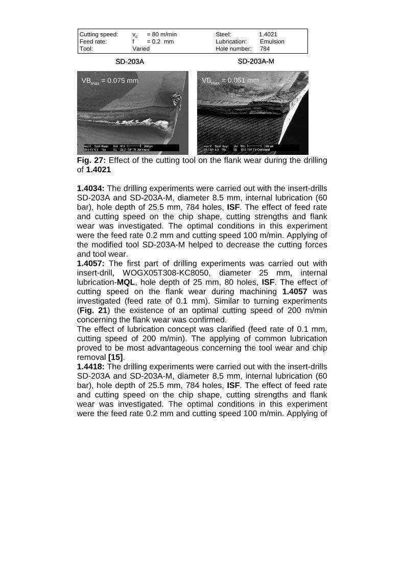
Fig. 26: Effect of the cutting speed on cutting strengths during the turning of 1.4542 4.4.3 Drilling of martensitic stainless steels 1.4021: The first part of drilling experiments was carried out with insert-drill, WOGX05T308-KC8050, diameter 25 mm, internal lubrication-MQL, hole depth of 25 mm, 96 holes, ISF. At first, the effect of lubrication concept was clarified (feed rate of 0.1 mm, cutting speed of 200 m/min). The applying of MQL was not advantageous concerning the tool wear and the chip removal. The better results could be achieved with the common lubrication [15]. The further experiments under applied common lubrication (60 bar) were carried out with the insert-drills SD-203A and SD-203A-M, diameter 8.5 mm, internal lubrication, hole depth of 25.5 mm, 784 holes. The optimal conditions in this experiment were a feed rate of 0.2 mm and cutting speed of 80 m/min. Once again applying the modified tool SD-203A-M helped to decrease the cutting forces and the tool wear (Fig. 27).
Cutting speed: vc = 80 m/min Steel: 1.4021Feed rate: f = 0.2 mm Lubrication: EmulsionTool: Varied Hole number: 784
SD-203A SD-203A-M
VBmax = 0.075 mm VBmax = 0.051 mm
Cutting speed: vc = 80 m/min Steel: 1.4021Feed rate: f = 0.2 mm Lubrication: EmulsionTool: Varied Hole number: 784
SD-203A SD-203A-M
VBmax = 0.075 mm VBmax = 0.051 mm
Fig. 27: Effect of the cutting tool on the flank wear during the drilling of 1.4021 1.4034: The drilling experiments were carried out with the insert-drills SD-203A and SD-203A-M, diameter 8.5 mm, internal lubrication (60 bar), hole depth of 25.5 mm, 784 holes, ISF. The effect of feed rate and cutting speed on the chip shape, cutting strengths and flank wear was investigated. The optimal conditions in this experiment were the feed rate 0.2 mm and cutting speed 100 m/min. Applying of the modified tool SD-203A-M helped to decrease the cutting forces and tool wear. 1.4057: The first part of drilling experiments was carried out with insert-drill, WOGX05T308-KC8050, diameter 25 mm, internal lubrication-MQL, hole depth of 25 mm, 80 holes, ISF. The effect of cutting speed on the flank wear during machining 1.4057 was investigated (feed rate of 0.1 mm). Similar to turning experiments (Fig. 21) the existence of an optimal cutting speed of 200 m/min concerning the flank wear was confirmed. The effect of lubrication concept was clarified (feed rate of 0.1 mm, cutting speed of 200 m/min). The applying of common lubrication proved to be most advantageous concerning the tool wear and chip removal [15]. 1.4418: The drilling experiments were carried out with the insert-drills SD-203A and SD-203A-M, diameter 8.5 mm, internal lubrication (60 bar), hole depth of 25.5 mm, 784 holes, ISF. The effect of feed rate and cutting speed on the chip shape, cutting strengths and flank wear was investigated. The optimal conditions in this experiment were the feed rate 0.2 mm and cutting speed 100 m/min. Applying of

the modified tool SD-203A-M helped to decrease the cutting forces and the tool wear. 1.4542: The drilling experiments were carried out with the insert-drills SD-203A and SD-203A-M, diameter 8.5 mm, internal lubrication (60 bar), hole depth of 25.5 mm, 784 holes, ISF. The effect of feed rate and cutting speed on the chip shape, cutting strengths and flank wear was investigated. The optimal conditions in this experiment were the feed rate 0.2 mm and cutting speed 100 m/min. Applying of the modified tool SD-203A-M helped to decrease the cutting forces and the tool wear. 5. Conclusion The machinability of selected widely used stainless steels (1.4307 (UNS S 30403), 1.4404 (UNS S 31603), 1.4571 (UNS S 31635), 1.4511, 1.4521 (UNS S 44400), 1.4362 (UNS S 32304), 1.4462 (UNS S 31803), 1.4021 (UNS S 42000), 1.4034, 1.4057 (UNS S 43100), 1.4418, 1.4542 (UNS S 17400) etc.) has been investigated. The cutting parameters (Vc, f, ap, tools and lubrication) were varied, in order to determine the optimal combinations concerning the productivity and surface quality. The investigation results have demonstrated that stainless steels can be machined under optimized conditions with good quality and high productivity. The experimentally determined ranges of turning parameters can be seen in Table 1. During the optimization parameter values should be increased from the minimal to the maximal values. For steels prone to the work hardening (austenitic and martensitic) there is always an optimal value of cutting speed, where the minimum of tool wear can be observed. The feed rate of such steels should be higher than 0.1 mm, in order to cut the material underneath of the hardened layer [9]. The low alloyed steels (1.4021, 1.4307 etc.) can be as a rule turned without emulsion. For the higher alloyed steels like 1.4404 or 1.4057 the MQL-concept proved to be beneficial. The high alloyed steels like 1.4462 require turning with emulsion. Concerning the chip form, it can be optimized by a thoroughly choice of feed rate and depth of cut. Another possibility is a proper chip-breaker geometry, for example MF4. Concerning the tool substrate materials, the tough, fine-grain, hard metals with a hardness >1420 HV30 and a bending strength > 2350 N/mm2 can be recommended. Regarding the tool coating materials,

good results were exhibited with one layer PVD TiAlN-coating 3-4 µm thick [15]. Table 1: Turning parameters Steel Hardness,
HB f, mm ap, mm Vc,
m/min Lubrication
Austenitic stainless steels 1.4307 152 0.2 - 0.3 1.0 - 3.5 200 - 270 Dry possible 1.4404 170 0.15 - 0.45 1.0 - 3.0 130 - 220 MQL 1.4571 173 0.15 - 0.45 1.0 - 3.0 140 - 230 MQL
Ferritic stainless steels 1.4511 155 ~ 0.25 ~ 1.0 ~ 250 - 1.4521 160 ~ 0.25 ~ 1.0 ~ 250 -
Duplex stainless steels 1.4362 205 ~ 0.25 ~ 1.0 ~ 250 - 1.4462 230 0.3 - 0.4 1.0 - 2.5 130 - 170 Emulsion
Martensitic stainless steels 1.4021 270 ~ 0.15 ~ 2.5 ~ 150 Dry possible 1.4057 275 0.2 - 0.4 1.0 - 2.5 130 - 220 MQL
Nickel-martensitic stainless steels 1.4418 300 0.3 - 0.5 1.0 - 2.0 130 - 200 -
Precipitation hardening martensitic stainless steels 1.4542 320 0.3 - 0.5 1.0 - 2.0 130 - 200 - The experimentally determined ranges of drilling (insert-drills Ø 6.0 - 8.5 mm) parameters can be seen in Table 2. During the optimization the parameters should be increased from the minimal values to the maximal. For steels prone to the work hardening there is always an optimal value of cutting speed, where the minimum of tool wear can be observed. The higher the hole diameter is, the higher will be the optimal cutting speed. Deeper holes require lower cutting speeds. For the work hardened material the cutting speed should be smaller as well (20-25 %) [10]. The testing of different lubrication concepts has shown that drilling with emulsion under high pressure (e.g. 60 bar) is the most optimal one. The reason is the rinsing effect of emulsion supporting the chip removal. Comparing of insert- and HSS-drillls demonstrated that, in the case of insert-drills, higher productivity can be realized.

Table 2: Drilling parameters (insert-drills Ø 6.0 - 8.5 mm) Steel Hardness, HB f, mm Vc, m/min
Austenitic stainless steels 1.4307 140 0.05 - 0.20 80 - 100 1.4404 130 0.1 - 0.2 80 - 100
Duplex stainless steels 1.4462 220 0.05 - 0.1 80 - 120
Martensitic stainless steels 1.4021 255 0.1 - 0.3 60 - 100 1.4034 180 0.1 - 0.3 80 - 120
Nickel-martensitic stainless steels 1.4418 330 0.1 - 0.3 80 - 120 Precipitation hardening martensitic stainless steels 1.4542 318 0.1 - 0.3 80 - 120 The machinability of these and other steels are being investigated together with ISF and Seco Tools. The further results will be reported. The machinability is a very comprehensive topic. It is not possible to clarify all nuances in one report. Deutsche Edelstahlwerke GmbH is always ready to consult its customers on the specific machining problems of these and other steels. References: [1] Eckstein, H.-J. (Hrsg.): Korrosionsbeständige Stähle. Deutscher Verlag für Grundstoffindustrie, Leipzig, 1990 [2] Kalwa, G.; Westerfeld, K.-J.: Rohre aus nichtrostendem Stahl. Stahl und Eisen. 107, 25/26, 1987, S. 69 - 72 [3] N.N.: Böhler-Edelstahlhandbuch, Version 2.0. Böhler Edelstahl GmbH, Kapfenberg, Österreich, 1997 [4] Firma Sandvik: Technisches Handbuch der Zerspanung [5] Klocke, F.; Gerschwiler, K.: Zerspanen von Stahl. MB 137, Stahl-Informations-Zentrum, 2008 [6] DIN 6584: Begriffe der Zerspantechnik; Kräfte, Energie, Arbeit, Leistungen [7] Tipnis, V.: Zerspanung rostfreier Stähle. Werkstatt und Betrieb, 104, 5, 1971, S. 323 - 330 [8] Schulte, K.: Stahlbearbeitung mit Wendeschneidplatten-Bohrern bei reduziertem Kühlschmierstoff-Durchsatz. Dissertation Universität Dortmund, Vulkan-Verlag, Essen 2000 [9] Jonsson, H.: Rostfreien Stahl drehen. Werkstatt und Betrieb, 127, 1994, 1/2, S. 68 - 70 [10] Bettenworth, E.; Bovensiepen, E.: Die Verarbeitung von Edelstahl Rostfrei. MB 822, Informationsstelle Edelstahl Rostfrei, 2001 [11] Prößler, E.; Kröger, H.: Labor Fertigungstechnik, Werkzeugmaschinen und Umformtechnik, Versuch Nr.: 1. Fachhochschule Stralsund

[12] Großmann, G.: Drehen austenitischer Stähle, VDI-Z Spezial Werkzeuge, 1994, S. 20 - 24 [13] Kalhöfer, E.; Kranzen, J.: Bohren rostfreier Stähle. WB, 3, 2009, S. 12 - 15 [14] Paro, J.: Machinability effects of stainless steels with a HIPed NiTi coating in high-efficiency machining operations. PhD Thesis, VTT PUBLICATIONS 610, ESPOO 2005 [15] Weinert, K., Hesterberg, S.: Einsatzmöglichkeiten der Trockenzerspanung und Minimalmengenkühlschmierung bei der Bearbeitung von hochlegierten, korrosionsbeständigen Stahlwerkstoffen. P568, Forschungsvereinigung Stahlanwendung [16] Nyström, N. Plastic deformation of Duplex Stainless Steels. Dissertation Chalmers University of Technology, 1995 [17] Melcher, G.: Drehen von rostbeständigen Stählen leicht gemacht. Maschinen Anlangen Verfahren, 10, 2000, S. 52 - 54 [18] Scherbarth, S.: Rostfreie Stähle effektiv zerspanen. Maschinen Anlagen Verfahren, 10, 2000, S. 68 - 69 [19] Gümpel, P.: Rostfreie Stähle. Expert-Verlag, Renningen, 2000