turbo-v 2k-g pumping system...turbo-v 2k-g pumping system models 969-8871 969-8873 manuale di...
TRANSCRIPT
Turbo-V 2K-G Pumping System
Models 969-8871 969-8873
Manuale di istruzioni Instruksjon manual Bedienungshandbuch Ohjekäsikirja Notice de mode d’emploi Felhasználói kézikönyv Manual de istrucciones Podrecznik instrukcji Manual de istruções Návod k použití Bedrijfshandleiding Návod na obsluhu Istrukstionsbog Priroÿnik za navodila Bruksanvisning User Manual 87-900-968-01 (G) 04/2011

Turbo-V 2K-G Pumping System User Manual / 87-900-968-01 (G)
Notices © Agilent Technologies, Inc. 2011
No part of this manual may be reproduced in any form or by any means (including electronic storage and retrieval or translation into a foreign language) without prior agreement and written consent from Agilent Technologies, Inc. as governed by United States and international copyright laws.
Manual Part Number Publication Number: 87-900-968-01 (G)
Edition Edition 04/2011
Printed in ITALY
Agilent Technologies Italia S.p.A.
Vacuum Products Division
Via F.lli Varian, 54
10040 Leinì (TO)
ITALY
Warranty The material contained in this document is provided “as is,” and is subject to being changed, without notice, in future editions. Further, to the maximum extent permitted by applicable law, Agilent disclaims all warranties, either express or implied, with regard to this manual and any information contained herein, including but not limited to the implied warranties of merchantability and fitness for a particular purpose. Agilent shall not be liable for errors or for incidental or consequential damages in connection with the furnishing, use, or performance of this document or of any information contained herein. Should Agilent and the user have a separate written agreement with warranty terms covering the material in this document that conflict with these terms, the warranty terms in the separate agreement shall control.
Technology Licenses The hardware and/or software described in this document are furnished under a license and may be used or copied only in accordance with the terms of such license.
Restricted Rights Legend If software is for use in the performance of a U.S. Government prime contract or subcontract, Software is delivered and licensed as “Commercial computer software” as defined in DFAR 252.227-7014 (June 1995), or as a “commercial item” as defined in FAR 2.101(a) or as “Restricted computer software” as defined in FAR 52.227-19 (June 1987) or any equivalent agency regulation or
contract clause. Use, duplication or disclosure of Software is subject to Agilent Technologies’ standard commercial license terms, and non-DOD Departments and Agencies of the U.S. Government will receive no greater than Restricted Rights as defined in FAR 52.227-19(c)(1-2) (June 1987). U.S. Government users will receive no greater than Limited Rights as defined in FAR 52.227-14 (June 1987) or DFAR 252.227-7015 (b)(2) (November 1995), as applicable in any technical data.
Trademarks Windows and MS Windows are U.S. registered trademarks of Microsoft Corporation.
Safety Notices
A CAUTION notice denotes a hazard. It calls attention to an operating procedure, practice, or the like that, if not correctly performed or adhered to, could result in damage to the product or loss of important data. Do not proceed beyond a CAUTION notice until the indicated conditions are fully understood and met.
A WARNING notice denotes a hazard. It calls attention to an operating procedure, practice, or the like that, if not correctly performed or adhered to, could result in personal injury or death. Do not proceed beyond a WARNING notice until the indicated conditions are fully understood and met.
WARNING
CAUTION

Turbo-V 2K-G
Turbo-V 2K-G Pumping System User Manual / 87-900-968-01 (G) 3/372
Turbo-V 2K-G

Turbo-V 2K-G
4/372 Turbo-V 2K-G Pumping System User Manual / 87-900-968-01 (G)
Contents
Turbo-V 2K-G Pumping System User Manual / 87-900-968-01 (G) 5/372
Contents
1 Istruzioni per l’uso 13�
Indicazioni di Sicurezza per Pompe Turbomolecolari 14�
Informazioni Generali 15�
Immagazzinamento 17�
Preparazione per l’installazione 18�
Installazione 20�
Uso 23�
Manutenzione 28�
Smaltimento 29�
2 Gebrauchsanleitung 31�
Sicherheitshinweise für Turbomolekularpumpen 32�
Allgemeine Informationen 33�
Lagerung 35�
Vor der Installation 36�
Installation 38�
Gebrauch 41�
Wartung 46�
Entsorgung 47�
Contents
6/372 Turbo-V 2K-G Pumping System User Manual / 87-900-968-01 (G)
3 Mode d’emploi 49�
Normes de sécurité pour Pompe Turbomoléculaires 50�
Indications generales 51�
Stockage 53�
Preparation pour l‘installation 54�
Installation 56�
Utilisation 59�
Entretien 64�
Mise au rebut 65�
4 Manual de istrucciones 67�
Indicaciones de Seguridad para Bombas Turbomoleculares 68�
Información general 69�
Almacenamiento 71�
Preparación para la instalación 72�
Instalación 74�
Uso 77�
Mantenimiento 82�
Eliminación 83�
5 Manual de Istruções 85�
Indicações de Segurança para Bombas Turbomoleculares 86�
Informações gerais 87�
Armazenagem 89�
Contents
Turbo-V 2K-G Pumping System User Manual / 87-900-968-01 (G) 7/372
Preparação para a instalação 90�
Instalação 92�
Utilização 95�
Manutenção 100�
Eliminação 101�
6 Bedrijfshandleiding 103�
Veiligheidsinstructies voor Turbomoleculaire pompen 104�
Algemene informatie 105�
Opslag 107�
Uitpakken 108�
Installatie 110�
Gebruik 113�
Onderhoud 118�
Afvalverwerking 119�
7 Istruktionsbog 121�
Sikkerhedsanvisninger for Molekylære turbopumper 122�
Generel Information 123�
Opbevaring 125�
Forberedelse før installation 126�
Installation 128�
Anvendelse 131�
Vedligeholdelse 136�
Contents
8/372 Turbo-V 2K-G Pumping System User Manual / 87-900-968-01 (G)
Bortskaffelse 137�
8 Bruksanvisning 139�
Säkerhetsanvisningar för Molekylära turbopumpar 140�
Allmän Information 141�
Förvaring 143�
Förberedelser för installationen 144�
Installation 146�
Användning 149�
Underhåll 154�
Bortskaffning 155�
9 Instruksjon Manual 157�
Sikkerhetsanvisninger for Turbomolekylære pumper 158�
Generell informasjon 159�
Lagring 161�
Klargjøre til installasjon 162�
Installasjon 164�
Bruk 167�
Vedlikehold 171�
Eliminering 172�
10 Ohjekäsikirja 173�
Turbomolekyylipumppujen Turvaohjeet 174�
Yleisiä tietoja 175�
Contents
Turbo-V 2K-G Pumping System User Manual / 87-900-968-01 (G) 9/372
Varastointi 177�
Valmistelut asennusta varten178�
Asennus 180�
Käyttö 183�
Huolto 188�
Hävittäminen 189�
11 Felhasználói Kézikönyv 191�
Biztonsági útmutató Turbómolekuláris szivattyúkhoz 192�
Általános információk 193�
Tárolás 195�
Elŋkészítés telepítésre 196�
Telepítés 198�
Használat 201�
Karbantartás 206�
Megsemmisítés 207�
12 Podrecznik Instrukcji 209�
Wskazówki dotyczĈce bezpieczeľstwa dla Pomp Turbomolekularnych 210�
Informacje ogolne 211�
Magazynowanie 213�
Przygotowanie do instalacji 214�
Instalacja 216�
Uůytkowanie 219�

Contents
10/372 Turbo-V 2K-G Pumping System User Manual / 87-900-968-01 (G)
Konserwacja 224�
Przetworstwo odpadow 225�
13 Návod k Použití 227�
Bezpeÿnostní návod pro Turbomolekulární vývĚvy 228�
Všeobecné informace 229�
UskladnĚní 231�
Pőíprava k instalaci 232�
Instalace 234�
Použití 237�
Údržba 242�
Likvidace 243�
14 Návod na Obsluhu 245�
Bezpeÿnostné návod pre Turbomolekulárne vývevy 246�
Všeobecné informácie 247�
Uchovávanie 249�
Príprava na inštaláciu 250�
Inštalácia 252�
Použitie 255�
Údržba 260�
Likvidácia 261�
15 Priroÿnik za Navodila 263�
Varnostna navodila za Turbomolekularne ÿrpalke 264�

Contents
Turbo-V 2K-G Pumping System User Manual / 87-900-968-01 (G) 11/372
Splošne informacije 265�
Shranjevanje 267�
Priprava za montažo 268�
Montaža 270�
Uporaba 273�
Vzdrževanje 278�
Odlaganje opadkov 279�
16 Instructions for Use 281�
Safety Guideline for Turbomolecular Pumps 282�
General Information 283�
Storage 285�
Preparation for Installation 286�
Installation 288�
Use 291�
Maintenance 296�
Disposal 297�
17 Technical Information 299�
Description of the Turbo-V 2K-G 301�
Technical Specification 306�
Turbo-V 2K-G Outline 309�
Interconnections 310�
Serial Cable Installation 319�
Contents
12/372 Turbo-V 2K-G Pumping System User Manual / 87-900-968-01 (G)
MoniTorr 330�
Profibus Option 343�
Profibus Message Mapping 349�
Inlet Screen Installation 359�
Water Cooling Connection 361�
Pump Purging and Venting 362�
High Vacuum Flange Connection 364�
Fore-Vacuum Pump Connection 365�
Pump Used in Presence of Magnetic Fields 365�
Orderable Parts 366�

Turbo-V 2K-G Pumping System User Manual
13/372
1 Istruzioni per l’uso Indicazioni di Sicurezza per Pompe Turbomolecolari 14 Informazioni Generali 15 Immagazzinamento 17 Preparazione per l’installazione 18 Installazione 20 Uso 23 Uso della Turbo-V 2K-G 24 Come avviare il sistema 24 Come arrestare la Turbo-V 2K-G 27 Arresto di Emergenza 27 Manutenzione 28 Smaltimento 29 Traduzione delle istruzioni originali
1 Istruzioni per l’uso Indicazioni di Sicurezza per Pompe Turbomolecolari
14/372 Turbo-V 2K-G Pumping System User Manual / 87-900-968-01 (G)
Indicazioni di Sicurezza per Pompe Turbomolecolari Le pompe Turbomolecolari descritte nel seguente Manuale di Istruzioni hanno una elevata quantità di energia cinetica dovuta alla alta velocità di rotazione in unione alla massa specifica dei loro rotori.
Nel caso di un guasto del sistema, ad esempio per un contatto tra rotore e statore o per una rottura del rotore, l'energia di rotazione potrebbe essere rilasciata.
AVVERTENZA!
Per evitare danni all'apparecchiatura e prevenire lesioni agli operatori, è necessario seguire attentamente le istruzioni di installazione descritte nel presente manuale!
Istruzioni per l’uso Informazioni Generali
1
Turbo-V 2K-G Pumping System User Manual / 87-900-968-01 (G) 15/372
Informazioni Generali Questa apparecchiatura è destinata ad uso professionale. L'utilizzatore deve leggere attentamente il presente manuale di istruzioni ed ogni altra informazione addizionale fornita dalla Agilent prima dell'utilizzo dell'apparecchiatura. La Agilent si ritiene sollevata da eventuali responsabilità dovute all'inosservanza totale o parziale delle istruzioni, ad uso improprio da parte di personale non addestrato, ad interventi non autorizzati o ad uso contrario alle normative nazionali specifiche.
La Turbo-V 2K-G è un sistema integrato costituito da una pompa turbomolecolare per applicazioni di alto e ultra alto vuoto e dal relativo controller. Il sistema è capace di pompare molti tipi di gas o di composto gassoso, ma non è adatto per il pompaggio di liquidi o di particelle solide.
L'effetto pompante è ottenuto tramite una turbina rotante ad elevata velocità (33000 giri/min. max) mossa da un motore elettrico trifase ad alto rendimento. La Turbo-V 2K-G è totalmente priva di agenti contaminanti, ed è quindi adatta per applicazioni che richiedono un vuoto "pulito".
Ha inoltre dei connettori ausiliari tramite i quali è possibile pilotarlo da remoto tramite un computer host collegato con linea seriale (RS232 o RS485).
Nei paragrafi seguenti sono riportate tutte le informazioni necessarie a garantire la sicurezza dell'operatore durante l'utilizzo dell'apparecchiatura. Informazioni dettagliate sono fornite nell'appendice “Technical information”.

1 Istruzioni per l’uso Informazioni Generali
16/372 Turbo-V 2K-G Pumping System User Manual / 87-900-968-01 (G)
Questo manuale utilizza le seguenti convenzioni:
AVVERTENZA!
I messaggi di avvertenza attirano l’attenzione dell’operatore su una procedura o una pratica specifica che, se non eseguita in modo corretto, potrebbe provocare gravi lesioni personali.
ATTENZIONE! I messaggi di attenzione sono visualizzati prima di procedure che, se non osservate, potrebbero causare danni all’apparecchiatura.
NOTA Le note contengono informazioni importanti estrapolate dal testo.

Istruzioni per l’uso Immagazzinamento
1
Turbo-V 2K-G Pumping System User Manual / 87-900-968-01 (G) 17/372
Immagazzinamento Per garantire il massimo livello di funzionalità ed affidabilità delle pompe Turbomolecolari Agilent, devono essere osservate le seguenti prescrizioni:
� durante il trasporto, lo spostamento e l'immagazzinamento delle pompe non devono essere superate le seguenti condizioni ambientali:
� temperatura: da –20 °C a 70 °C
� umidità relativa: da 0 a 95 % (non condensante)
� il cliente deve sempre avviare le pompe turbomolecolari nel modo Soft-Start quando ricevute e messe in funzione per la prima volta
� il tempo di immagazzinamento di una pompa turbomolecolare è di 10 mesi dalla data di spedizione.
ATTENZIONE! Se, per qualsiasi ragione, il tempo di immagazzinamento è superiore, occorre reinviare la pompa in fabbrica. Per ogni informazione, si prega di contattare il locale rappresentante della Agilent.
1 Istruzioni per l’uso Preparazione per l’installazione
18/372 Turbo-V 2K-G Pumping System User Manual / 87-900-968-01 (G)
Preparazione per l’installazione La Turbo-V 2K-G viene fornita in un imballo protettivo speciale; se si presentano segni di danni, che potrebbero essersi verificati durante il trasporto, contattare l'ufficio vendite locale.
Durante l'operazione di disimballaggio, prestare particolare attenzione a non lasciar cadere la Turbo-V 2K-G e a non sottoporla ad urti o vibrazioni.
Rimuovere la protezione dei connettori solo dopo che la turbopompa è stata fissata al sistema.
A causa del suo peso (35 kg) per estrarre la pompa dall'imballo utilizzare i tre golfari a 120 ° avvitati sul corpo pompa.
Non disperdere l'imballo nell'ambiente. Il materiale è completamente riciclabile e risponde alla direttiva CEE 85/399 per la tutela dell'ambiente.
ATTENZIONE! Onde evitare problemi di degasamento, non toccare con le mani nude i componenti destinati ad essere esposti al vuoto. Utilizzare sempre i guanti o altra protezione adeguata.
NOTA La Turbo-V 2K-G non può essere danneggiata rimanendo semplicemente esposta all'atmosfera. Si consiglia comunque di mantenere la pompa chiusa e sigillata fino al momento dell'installazione sul sistema. Questo per prevenire la contaminazione del sistema.
Istruzioni per l’uso Preparazione per l’installazione
1
Turbo-V 2K-G Pumping System User Manual / 87-900-968-01 (G) 19/372
Figura 1
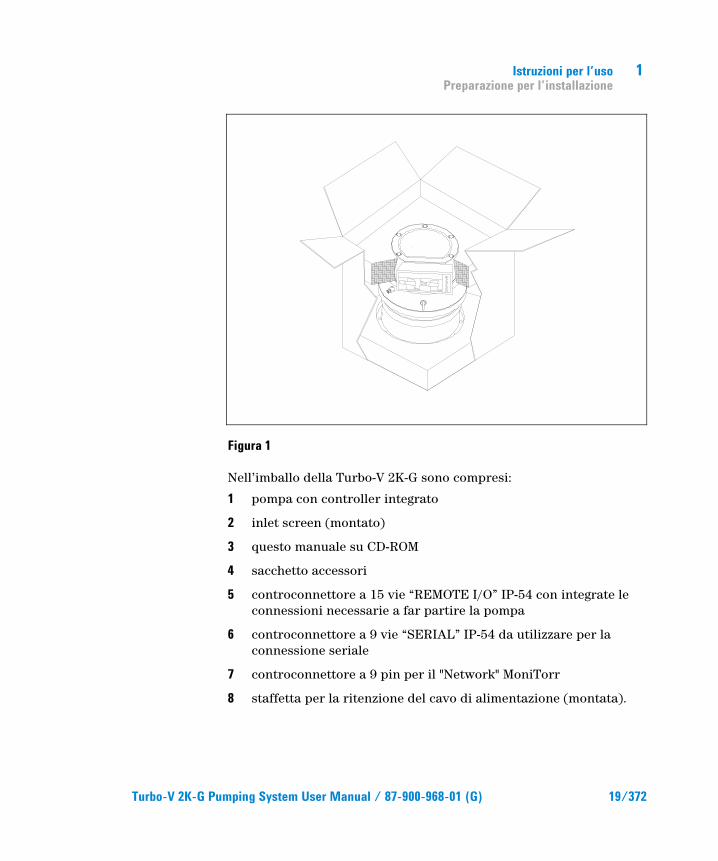
Nell’imballo della Turbo-V 2K-G sono compresi:
1 pompa con controller integrato
2 inlet screen (montato)
3 questo manuale su CD-ROM
4 sacchetto accessori
5 controconnettore a 15 vie “REMOTE I/O” IP-54 con integrate le connessioni necessarie a far partire la pompa
6 controconnettore a 9 vie “SERIAL” IP-54 da utilizzare per la connessione seriale
7 controconnettore a 9 pin per il "Network" MoniTorr
8 staffetta per la ritenzione del cavo di alimentazione (montata).

1 Istruzioni per l’uso Installazione
20/372 Turbo-V 2K-G Pumping System User Manual / 87-900-968-01 (G)
Installazione
AVVERTENZA!
La pompa, a causa del suo peso, deve essere maneggiata tramite appositi attrezzi di sollevamento e spostamento. All’uopo utilizzare gli appositi golfari avvitati nei fori filettati praticati sul corpo pompa.
ATTENZIONE! Non rimuovere la copertura imbullonata prima del collegamento della turbopompa al sistema.
ATTENZIONE! Rimuovere la protezione dei connettori solo dopo che la turbopompa è stata fissata al sistema.
Figura 2
Non installare e/o utilizzare la pompa in ambienti esposti ad agenti atmosferici (pioggia, gelo, neve), polveri, gas aggressivi, in ambienti esplosivi o con elevato rischio di incendio.
WA
RN
ING
REMOVE THIS PROTECTION AFTER
MECHANICAL INSTALLATION
NO
CHAMBER
YES
Istruzioni per l’uso Installazione
1
Turbo-V 2K-G Pumping System User Manual / 87-900-968-01 (G) 21/372
Durante il funzionamento è necessario che siano rispettate le seguenti condizioni ambientali:
� pressione massima: 2 bar oltre la pressione atmosferica
� temperatura: da + 5 °C a +35 °C (vedere grafico nell’appendice “Technical Information”)
� umidità relativa: 0 – 95 % (non condensante).
In presenza di campi elettromagnetici la pompa deve essere protetta tramite opportuni schermi. Vedere l'appendice "Technical Information" per ulteriori dettagli.
La Turbo-V 2K-G deve essere collegata ad una pompa primaria (vedere schema in "Technical Information").
La Turbo-V 2K-G può essere installata in qualsiasi posizione. Fissare la Turbo-V 2K-G in posizione stabile collegando la flangia di ingresso della turbopompa ad una controflangia fissa capace di resistere ad una coppia di 10600 Nm attorno al proprio asse.
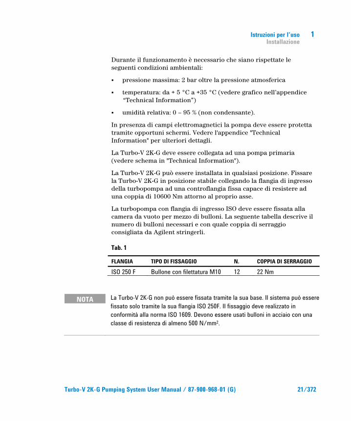
La turbopompa con flangia di ingresso ISO deve essere fissata alla camera da vuoto per mezzo di bulloni. La seguente tabella descrive il numero di bulloni necessari e con quale coppia di serraggio consigliata da Agilent stringerli.
Tab. 1
FLANGIA TIPO DI FISSAGGIO N. COPPIA DI SERRAGGIO
ISO 250 F Bullone con filettatura M10 12 22 Nm
NOTA La Turbo-V 2K-G non può essere fissata tramite la sua base. Il sistema può essere fissato solo tramite la sua flangia ISO 250F. Il fissaggio deve realizzato in conformità alla norma ISO 1609. Devono essere usati bulloni in acciaio con una classe di resistenza di almeno 500 N/mm2.

1 Istruzioni per l’uso Installazione
22/372 Turbo-V 2K-G Pumping System User Manual / 87-900-968-01 (G)
ATTENZIONE! La Turbo-V 2K-G appartiene alla seconda categoria di installazione (o sovratensione) prevista dalla normativa EN 61010-1. Connettere quindi il dispositivo ad una linea di alimentazione che soddisfi tale categoria. Utilizzare i controconnettori in dotazione per garantire l'isolamento IP-54. La Turbo-V 2K-G ha dei connettori per gli ingressi/uscite e per la comunicazione seriale che devono essere connessi ai circuiti esterni in modo che nessuna parte sotto tensione sia accessibile. Assicurarsi che l’isolamento del dispositivo connesso alla Turbo-V 2K-G abbia un isolamento adeguato anche in condizione di guasto singolo come previsto dalla normativa EN 61010-1.
Per l'installazione degli accessori opzionali, vedere "Technical Information".
Istruzioni per l’uso Uso
1
Turbo-V 2K-G Pumping System User Manual / 87-900-968-01 (G) 23/372
Uso In questo paragrafo sono riportate le principali procedure operative. Prima di usare il sistema effettuare tutti i collegamenti elettrici e pneumatici. Durante l'eventuale riscaldamento della camera da vuoto, la temperatura sulla flangia di ingresso non deve essere superiore a 80 °C. Durante il funzionamento della pompa la temperatura del rotore non deve mai superare i 120 °C. L'operatore deve assicurarsi di predisporre il corretto modo di funzionamento in funzione del gas da pompare: 1 per Azoto e gas più leggeri, 0 per Argon (modo di default). Per ulteriori dettagli vedere l'appendice "Technical Information".
AVVERTENZA!
Non far funzionare mai la pompa se la flangia di ingresso non è collegata alla camera a vuoto o non è chiusa con la flangia di chiusura. Non toccare la turbopompa e i suoi eventuali accessori durante le operazioni di riscaldamento. L'elevata temperatura può causare lesioni alle persone.
ATTENZIONE! Evitare urti, oscillazioni o bruschi spostamenti della turbopompa quando è in funzione. I cuscinetti potrebbero danneggiarsi. Per la mandata all'aria della pompa utilizzare aria o gas inerte esente da polvere o particelle. La pressione di ingresso attraverso l'apposita porta deve essere inferiore a 1 bar (oltre la pressione atmosferica). Per il pompaggio di gas contenenti particolato o inquinanti aggressivi per i cuscinetti, queste pompe sono dotate di una apposita porta attraverso la quale è necessario fornire alla pompa un flusso di gas inerte (Azoto o Elio) per proteggere i cuscinetti (vedere l'appendice "Technical Information").
ATTENZIONE! Non usare mai la pompa in presenza di gas o vapori corrosivi che possano danneggiare i materiali interni alla pompa.
1 Istruzioni per l’uso Uso
24/372 Turbo-V 2K-G Pumping System User Manual / 87-900-968-01 (G)
AVVERTENZA!
Quando la pompa viene utilizzata per il pompaggio di gas tossici, infiammabili o radioattivi, seguire le appropriate procedure tipiche di ciascun gas. Non usare la pompa in presenza di gas esplosivi. La pompa è progettata per avere un alto trasferimento di Azoto, Argon e gas più leggeri. Nel caso in cui ci fosse la necessità di pompare gas più pesanti dell'Argon si prega di prendere contatti con l'Assistenza Tecnica della Agilent per informazioni.
Uso della Turbo-V 2K-G
Come avviare il sistema Prima dell'avvio del sistema, controllare che il controconnettore I/O sia rimosso. Se il sistema è collegato ad un dispositivo di Inpu/Output remoto, assicurarsi che il segnale di STOP sia attivo (vedere il paragrafo "J1 – REMOTE I/O" nell'appendice "Technical Information").
Per avviare il sistema eseguire i seguenti passi:
1 rimuovere (se presente) il controconnettore I/O
2 collegare l'alimentazione di rete
3 portare la pressione all0'interno della camera a vuoto a 0,1 mbar
4 fornire alla Turbo-V 2K-G il segnale di START in uno dei seguenti modi:
a collegare il controconnettore I/O in dotazione
b dare il segnale di START da remoto tramite il connettore I/O (vedere il paragrafo "J1 – REMOTE I/O" nell'appendice "Technical Information")
c dare il segnale di START da remoto tramite l'interfaccia seriale RS 232/485 (vedere il paragrafo "RS 232/485 Communication Description" nell'appendice "Technical Information").

Istruzioni per l’uso Uso
1
Turbo-V 2K-G Pumping System User Manual / 87-900-968-01 (G) 25/372
AVVERTENZA!
Quando viene fornita l'alimentazione ed il controconnettore a 15 pin in dotazione è inserito, la Turbo-V 2K-G si avvia automaticamente.
ATTENZIONE! Il controller viene fornito già connesso meccanicamente ed elettricamente alla pompa. La separazione del controller dal corpo pompa può solo essere effettuata da personale autorizzato dalla Agilent Vacuum Technologies.
NOTA Quando si avvia la Turbo-V 2K-G per la prima volta, il controller automaticamente avvia il sistema con una procedura speciale che protegge i cuscinetti da possibili danni (SOFT START). Il sistema viene avviato a passi successivi fino alla piena velocità in un tempo che varia da 10 minuti fino ad 1 ora. Dopo che il sistema ha raggiunto la piena velocità, la procedura di "soft start" viene disabilitata e gli avvii successivi vengono eseguiti nel modo normale.
NOTA Per mantenere il livello di protezione IP-54 utilizzare esclusi-vamente i connettori forniti con la pompa. Per il cavo di alimen-tazione utilizzare solo i PN: 969-9957 or 969-9958, e fissare il cavo al controller con l’apposita staffetta (vedere la figura seguente). Utilizzare questo cavo e spina insieme ad una presa adeguatamente connessa a terra per evitare scosse elettriche e soddisfare i requisiti delle norme CE.
1 Istruzioni per l’uso Uso
26/372 Turbo-V 2K-G Pumping System User Manual / 87-900-968-01 (G)
Figura 3
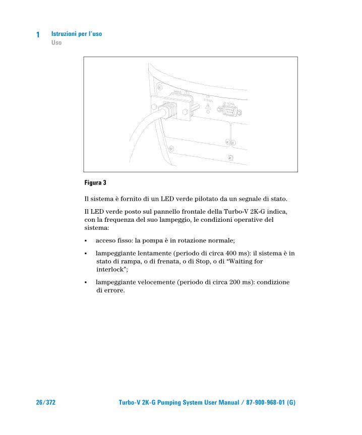
Il sistema è fornito di un LED verde pilotato da un segnale di stato.
Il LED verde posto sul pannello frontale della Turbo-V 2K-G indica, con la frequenza del suo lampeggio, le condizioni operative del sistema:
� acceso fisso: la pompa è in rotazione normale;
� lampeggiante lentamente (periodo di circa 400 ms): il sistema è in stato di rampa, o di frenata, o di Stop, o di “Waiting for interlock”;
� lampeggiante velocemente (periodo di circa 200 ms): condizione di errore.
Istruzioni per l’uso Uso
1
Turbo-V 2K-G Pumping System User Manual / 87-900-968-01 (G) 27/372
Come arrestare la Turbo-V 2K-G Per arrestare la pompa si può usare uno dei seguenti metodi:
1 togliendo il controconnettore di I/O in dotazione
2 inviando un segnale di STOP da remoto tramite il connettore I/O (vedere il paragrafo "J1 – REMOTE I/O" nell'appendice "Technical Information")
3 inviando un segnale di STOP da remoto tramite l'interfaccia seriale RS 232/485 (vedere il paragrafo "RS 232/485 Communication Description" nell'appendice "Technical Information").
Arresto di Emergenza Per arrestare immediatamente in condizioni di emergenza la Turbo-V 2K-G occorre staccare il cavo di alimentazione dall'alimentazione. Occorre però tenere conto che questa operazione oltre a disabilitare completamente l'alimentazione della pompa disabilita anche tutte le altre funzionalità del controller come ad esempio la gestione del Purge e del Vent Controllato e la capacità di comunicare con il sistema in cui la pompa è stata integrata via I/Os, Seriale o Profibus.
Inoltre, questa operazione non può garantire l'arresto immediato del rotore la cui velocità di rotazione diminuirà in funzione del grado di vuoto presente nel sistema.

1 Istruzioni per l’uso Manutenzione
28/372 Turbo-V 2K-G Pumping System User Manual / 87-900-968-01 (G)
Manutenzione Il Turbo-V 2K-G non richiede alcuna manutenzione. Qualsiasi intervento deve essere eseguito da personale autorizzato.
AVVERTENZA!
Prima di effettuare qualsiasi intervento sul sistema scollegarlo dall’alimentazione, mandare all'aria la pompa aprendo l'apposita valvola, attendere fino al completo arresto del rotore ed attendere che la temperatura superficiale della pompa sia inferiore a 50 °C.
In caso di guasto è possibile usufruire del servizio di riparazione Agilent o del "Agilent advanced exchange service", che permette di ottenere un sistema rigenerato in sostituzione di quello guasto.
NOTA Prima di rispedire al costruttore una pompa per riparazioni o advanced exchange service, è indispensabile compilare e far pervenire al locale ufficio vendite la scheda "Sicurezza e Salute" allegata al presente manuale di istruzioni. Copia della stessa deve essere inserita nell'imballo del sistema prima della spedizione.
Qualora un sistema dovesse essere rottamato, procedere alla sua eliminazione nel rispetto delle normative nazionali specifiche.

Istruzioni per l’uso Smaltimento
1
Turbo-V 2K-G Pumping System User Manual / 87-900-968-01 (G) 29/372
Smaltimento Significato del logo "WEEE" presente sulle etichette. Il simbolo qui sotto riportato è applicato in ottemperanza alla direttiva CE denominata "WEEE". Questo simbolo (valido solo per i paesi della Comunità Europea) indica che il prodotto sul quale è applicato, NON deve essere smaltito insieme ai comuni rifiuti domestici o industriali, ma deve essere avviato ad un sistema di raccolta differenziata. Si invita pertanto l'utente finale a contattare il fornitore del dispositivo, sia esso la casa madre o un rivenditore, per avviare il processo di raccolta e smaltimento, dopo opportuna verifica dei termini e condizioni contrattuali di vendita.

1 Istruzioni per l’uso Smaltimento
30/372 Turbo-V 2K-G Pumping System User Manual / 87-900-968-01 (G)
Turbo-V 2K-G Pumping System User Manual
31/372
2 Gebrauchsanleitung Sicherheitshinweise für Turbomolekularpumpen 32 Allgemeine Informationen 33 Lagerung 35 Vor der Installation 36 Installation 38 Gebrauch 41 Benutzung der Turbo-V 2K-G42 Ingangsetzung des Systems 42 Stillsetzung der Turbo-V 2K-G 45 Not-Aus 45 Wartung 46 Entsorgung 47 Übersetzung der Originalanleitungen
2 Gebrauchsanleitung Sicherheitshinweise für Turbomolekularpumpen
32/372 Turbo-V 2K-G Pumping System User Manual / 87-900-968-01 (G)
Sicherheitshinweise für Turbomolekularpumpen Die in der folgenden Gebrauchsanweisung beschriebenen Turbomolekularpumpen verfügen aufgrund der hohen Rotationsgeschwindigkeit in Verbindung mit dem spezifischen Gewicht ihrer Rotoren über eine große Menge kinetischer Energie.
Im Falle eines Systemdefekts, z.B. durch einen Kontakt zwischen Rotor und Stator oder durch einen Rotorbruch, könnte diese Rotationsenergie freigesetzt werden.
WARNUNG!
Um Schäden am Gerät zu vermeiden und um Verletzungen der Bediener vorzubeugen, befolgen Sie bitte aufmerksam die in diesem Handbuch beschriebenen Installationshinweise!
Gebrauchsanleitung Allgemeine Informationen
2
Turbo-V 2K-G Pumping System User Manual / 87-900-968-01 (G) 33/372
Allgemeine Informationen Dieser Apparat ist für den fachmännischen Gebrauch bestimmt. Vor dem Gebrauch hat der Benutzer dieses Handbuch sowie alle weiteren mitgelieferten Zusatzdokumentationen genau zu lesen. Bei auch teilweiser Nichtbeachtung der enthaltenen Anweisungen, unsachgemäßem Gebrauch durch ungeschultes Personal, nicht autorisierten Eingriffen und Mißachtung der nationalen einschlägigen Normen übernimmt die Firma Agilent keinerlei Haftung.
Modell Turbo-V 2K-G ist ein integriertes System, das aus einer Turbomolekularpumpe für Hoch- und Höchstvakuum-anwendungen, integriert mit einem entsprechenden Controller, besteht. Das System kann viele Arten von Gas oder gasförmigen Gemischen pumpen, ist jedoch nicht für das Pumpen von Flüssigkeiten oder Festkörperpartikeln geeignet.
Die Pumpwirkung wird durch eine hochtourige Turbine (max. 33000 1/min) erreicht, die von einem Hochleistungs-drehstrommotor angetrieben wird. Modell Turbo-V 2K-G enthält keinerlei umweltschädliche Substanzen und eignet sich deshalb auch für Anwendungen, die ein "sauberes" Vakuum erfordern.
Es verfügt des Weiteren über Hilfskonnektoren, über die es von einem Host-Rechner mit seriellem Anschluss (RS232 oder RS485) ferngesteuert werden kann.
In den folgenden Abschnitten sind alle erforderlichen Informationen für die Sicherheit des Bedieners bei der Anwendung des Geräts aufgeführt. Detaillierte technische Informationen sind im Anhang "Technical Information" enthalten.
2 Gebrauchsanleitung Allgemeine Informationen
34/372 Turbo-V 2K-G Pumping System User Manual / 87-900-968-01 (G)
In dieser Gebrauchsanleitung werden Sicherheitshinweise folgendermaßen hervorgehoben:
WARNUNG!
Die Warnhinweise lenken die Aufmerksamkeit des Bedieners auf einen Vorgang oder eine bestimmte Ausführungsweise, die bei unkorrekter Ausführung schwere Verletzungen hervorrufen könnten.
VORSICHT! Die Vorsichtshinweise werden vor Vorgängen angegeben, die bei Nichtbeachtung Schäden an der Anlage verursachen könnten.
HINWEIS Die Hinweise enthalten wichtige Informationen, die aus dem Text hervorgehoben werden.
Gebrauchsanleitung Lagerung
2
Turbo-V 2K-G Pumping System User Manual / 87-900-968-01 (G) 35/372
Lagerung Um ein Höchstmaß an Effizienz und Zuverlässigkeit der Agilent Turbomolekularpumpen zu gewährleisten, sind die folgenden Anweisungen zu beachten:
� Während des Transports, der Handhabung und der Einlagerung der Pumpen dürfen die folgenden Grenzwerte nicht überschritten werden:
� Temperatur: von –20 °C bis 70 °C
� Relative Feuchtigkeit: von 0 bis 95 % (nicht kondensierend)
� Der Kunde hat die Turbomolekularpumpen nach dem Empfang bei Erstinbetriebnahme stets im Modus Soft-Start in Gang zu setzen.
� Die Lagerdauer für eine Turbomolekularpumpe beträgt 10 Monate ab dem Speditionsdatum.
VORSICHT! Falls die Lagerdauer aus verschiedenen Gründen die genannte Frist überschreiten sollte, ist die Pumpe an das Werk zurückzusenden. Für Informationen wenden Sie sich bitte an den örtlichen Agilent Vertreter.
2 Gebrauchsanleitung Vor der Installation
36/372 Turbo-V 2K-G Pumping System User Manual / 87-900-968-01 (G)
Vor der Installation Modell Turbo-V 2K-G wird in einer speziellen Schutzverpa-ckung geliefert. Eventuelle Transportschäden sind der zuständigen örtlichen Verkaufsstelle zu melden. Modell Turbo-V 2K-G ist vorsichtig auszupacken, wobei es vor dem Herunterfallen und vor Stößen und Vibrationen zu schützen ist. Das Verpackungsmaterial ist vorschriftsgemäß zu entsorgen.
Den Schutz der Steckverbinder erst entfernen, wenn die Turbopumpe am System befestigt ist.
Für die Entnahme der Pumpe aus ihrer Verpackung sind, aufgrund des hohen Gewichtes (35 kg), die drei um 120 °C versetzten Ösenschrauben zu benutzen, die am Pumpenkorpus angeschraubt sind.
Es ist vollständig recyclebar und entspricht der Richtlinie 85/399/EWG für Umweltschutz.
VORSICHT! Um Entgasungen zu vermeiden, dürfen die Teile, die mit dem Vakuum in Berührung kommen, nicht mit den bloßen Händen angefasst werden. Es sind stets Schutzhandschuhe oder andere Schutzmittel zu verwenden.
HINWEIS Die Turbo-V 2K-G kann durch ledigliche Einwirkung von atmo-sphärischen Bedingungen nicht beschädigt werden. Es wird indes empfohlen, die Pumpe bis zur Installation am System geschlossen und versiegelt zu halten. Auf diese Weise kann der Verunreinigung des Systems vorgebeugt werden.

Gebrauchsanleitung Vor der Installation
2
Turbo-V 2K-G Pumping System User Manual / 87-900-968-01 (G) 37/372
Abbildung 1
Verpackungsinhalt der Turbo-V 2K-G:
1 Pumpe mit integriertem Controller
2 Inlet-Screen (montiert)
3 Betriebsanleitung auf CD-ROM
4 Beutel mit Zubehör
5 Gegenkonnektor mit 15 PINs “REMOTE I/O” IP-54 mit integrierten Anschlüssen für den Pumpenanlauf
6 Gegenkonnektor mit 9 PINs “SERIAL” IP-54 für den seriellen Anschluss
7 Gegenkonnektor mit 9 PINs "Network" MoniTorr
8 Halteschelle für das Stromversorgungskabel (montiert).

2 Gebrauchsanleitung Installation
38/372 Turbo-V 2K-G Pumping System User Manual / 87-900-968-01 (G)
Installation
WARNUNG!
Die Pumpe ist aufgrund ihres hohen Gewichtes mit geeigneten Hebe- und Förderzeugen zu handhaben. Zu diesen Zwecken sind die Ösenschrauben zu benutzen, die in die Gewindebohrungen am Pumpenkorpus eingeschraubt sind.
VORSICHT! Die angeschraubte Abdeckung darf erst nach Anschluss der Turbopumpe an das System entfernt werden.
VORSICHT! Den Schutz der Steckverbinder erst entfernen, wenn die Turbopumpe am System befestigt ist.
Abbildung 2
Die Pumpe darf nicht in Umgebungen, die ungeschützt vor Wetter (Regen, Frost, Schnee), Staub und aggressiven Gasen sind, sowie auch nicht in explosionsfähigen oder erhöht brandgefährdeten Umgebungen installiert und/oder benutzt werden.
WA
RN
ING
REMOVE THIS PROTECTION AFTER
MECHANICAL INSTALLATION
NO
CHAMBER
YES
Gebrauchsanleitung Installation
2
Turbo-V 2K-G Pumping System User Manual / 87-900-968-01 (G) 39/372
Beim Betrieb müssen folgende Umgebungsbedingungen eingehalten werden:
� Maximaler Druck: 2 bar über dem atmosphärischen Druck
� Temperatur: von +5 °C bis +40 °C (siehe Diagramm im Anhang "Technical Information")
� Relative Luftfeuchtigkeit: 0 – 95 % (nicht kondensierend).
Bei Vorhandensein von elektromagnetischen Feldern ist die Pumpe entsprechend abzuschirmen. Für ausführliche Informationen siehe im Anhang "Technical Information".
Modell Turbo-V 2K-G ist an eine Primärpumpe anzuschließen (siehe Schema in "Technical Information"). Modell Turbo-V 2K-G kann in jeder beliebigen Position installiert werden.
Modell Turbo-V 2K-G ist stabil zu befestigen, indem der Flansch am Eingang der Turbopumpe an einen festen Gegenflansch angeschlossen wird, der mit einem Drehmoment von 10600 Nm um seine eigene Achse belastbar ist.
Die Turbopumpe mit dem ISO-Eintrittsflansch ist mittels Mutterschrauben an der Vakuumkammer zu befestigen. In der nachstehenden Tabelle sind die Anzahl der erforderlichen Mutterschrauben und die von Agilent empfohlenen Anzugsmomente angegeben.
Tab. 1
FLANSCH KLEMMSCHELLE ANZ. ANZUGSMOMENT
ISO 250 F Mutterschraube mit Gewinde M10 12 22 Nm
HINWEIS Die Turbo-V 2K-G kann nicht über ihren Sockel befestigt werden. Zur Befestigung des Systems ist der Flansch ISO 250F zu verwenden. Die Befestigung muss nach ISO 1609 ausgeführt sein. Es sind Mutterschrauben aus Stahl mit einer Festigkeitsklasse von mindestens 500 N/mm2 zu verwenden.

2 Gebrauchsanleitung Installation
40/372 Turbo-V 2K-G Pumping System User Manual / 87-900-968-01 (G)
VORSICHT! Der Turbo-V 2K-G gehört zur zweiten Installationsklasse (Überdruck) die von den Normen EN 61010-1 vorgesehen ist. Die Vorrichtung muß daher an eine Speisungsleitung angeschlossen werden, die dieser Kategorie entspricht. Zur Gewährleistung der Schutzart IP-54 sind die Gegenkonnektoren zu verwenden. Der Turbo-V 2K-G hat Verbinder für den Ein-und Ausgang und die Schnittstellenkommunikation, die an die Außenkreise angeschlossen werden müssen, sodaß kein Teil unter Spannung zugänglich ist. Sicherstellen, daß die Isolierung der an den Turbo-V 2K-G angeschlossenen Vorrichtung auch bei einer Einzelstörung ausreichend isoliert, wie es von der Richtlinie EN 61010-1 vorgesehen wird.
Für die Installation der Optionsteile siehe im Anhang "Technical Information".

Gebrauchsanleitung Gebrauch
2
Turbo-V 2K-G Pumping System User Manual / 87-900-968-01 (G) 41/372
Gebrauch In diesem Abschnitt werden die wichtigsten Betriebsvorgänge erläutert. Vor Benutzung des Systems sind alle elektrischen und pneumatischen Anschlüsse auszuführen.
Während der eventuellen Aufheizung der Vakuumkammer darf die Temperatur am Eingangsflansch 80 °C nicht überschreiten.
Während des Pumpenbetriebs darf die Temperatur des Läufers niemals 120 °C überschreiten.
Der Bediener hat sich zu vergewissern, dass die richtige Betriebsart in Abhängigkeit von dem zu pumpenden Gas eingestellt ist: 1 für Stickstoff und leichtere Gase, 0 für Argon (voreingestellte Betriebsart). Für ausführliche Informationen siehe im Anhang "Technical Information".
WARNUNG!
Die Pumpe darf nicht in Betrieb genommen werden, wenn der Eingangsflansch nicht an die Vakuumkammer angeschlossen oder nicht mit dem Verschlussflansch verschlossen ist. Während des Aufheizens dürfen weder die Pumpe noch eventuelle heiße Zubehörteile berührt werden. Es besteht Verbrennungsgefahr.
VORSICHT! Während des Betriebs sind Stoß- und Vibrationseinwirkungen sowie Ruckbewegungen an der Turbopumpe zu vermeiden, da die Lager beschädigt werden könnten. Für die Belüftung der Pumpe trockene staub und partikelfreie Luft oder Inertgase verwenden. Der Eingangsdruck am Belüftungsanschluß soll unter 1 bar (über dem atmosphärischen Druck) betragen. Zum Pumpen von Gasen mit Partikeln oder aggressiven Schadstoffe für die Lager, sind die Pumpen mit einer Öff-nungsklappe ausgestattet, über die zum Schutz der Lager Inertgas (Stickstoff oder Helium) zuzuleiten ist (siehe Anhang "Technical Information").

2 Gebrauchsanleitung Gebrauch
42/372 Turbo-V 2K-G Pumping System User Manual / 87-900-968-01 (G)
WARNUNG!
Wenn die Pumpe zur Förderung von giftigen, leicht entflammbaren oder radioaktiven Gasen benutzt wird, sind die für das jeweilige Gas vorgeschriebenen Vorgänge und Maßnahmen zu befolgen. Die Pumpe darf niemals bei Vorhandensein von explosionsfähigen Gasen verwendet werden. Die Pumpe ist für einen hohen Durchsatz an Stickstoff, Argon und leichteren Gasen konzipiert. Falls das Pumpen von Gasen erforderlich ist, die schwerer als Argon sind, ist mit dem Technischen Kundendienst von Agilent Rücksprache zu halten.
Benutzung der Turbo-V 2K-G
Ingangsetzung des Systems Vor der Ingangsetzung des Systems ist zu kontrollieren, dass der E/A-Gegenkonnektor entfernt ist. Wenn das System an eine Vorrichtung für die Ferneingabe/-ausgabe angeschlossen ist, ist zu überprüfen, dass das Signal STOP aktiv ist (siehe Abschnitt "J1 – REMOTE I/O " im Anhang "Technical Information").
Zur Ingangsetzung des Systems sind die folgenden Schritte auszuführen:
1 E/A-Gegenkonnektor entfernen (sofern vorhanden)
2 Gerät an das Netz anschließen
3 Druck in der Vakuumkammer auf 0,1 mbar bringen.
4 Für die Erteilung des Signals START an die Turbo-V 2K-G gibt es die folgenden Möglichkeiten:
a Mitgelieferten E/A-Gegenkonnektor anschließen.
b Das Signal START von der Fernsteuerung über den E/A-Konnektor geben (siehe Abschnitt "J1 – REMOTE I/O" im Anhang "Technical Information").
Gebrauchsanleitung Gebrauch
2
Turbo-V 2K-G Pumping System User Manual / 87-900-968-01 (G) 43/372
c Das Signal START von der Fernsteuerung über die serielle Schnittstelle RS 232/485 geben (siehe Abschnitt "RS 232/485 Communication Description" im Anhang "Technical Information").
WARNUNG!
Wenn die Spannung zugeschaltet und der Gegenkonnektor mit 15 PINs angeschlossen ist, startet die Turbo-V 2K-G automatisch.
VORSICHT! Im Lieferumfang ist der mechanisch und elektrisch an die Pumpe angeschlossene Controller enthalten. Die Trennung des Controllers vom Pumpenkorpus darf nur von Personen ausgeführt werden, die von Agilent Vacuum Technologies autorisiert sind.
HINWEIS Bei Erstingangsetzung der Turbo-V 2K-G startet der Controller das System mit einer Spezialprozedur, um die Kugellager vor etwaigen Schäden zu schützen (SOFT START). Das System wird innerhalb von 10 min bis zu 1 h in aufeinander folgenden Schritten bis zur Arbeitsgeschwindigkeit gestartet. Sobald das System die Arbeitsgeschwindigkeit erreicht hat, wird die "soft start"-Prozedur deaktiviert. Die darauf folgenden Anlaufvorgänge werden normal ausgeführt.

2 Gebrauchsanleitung Gebrauch
44/372 Turbo-V 2K-G Pumping System User Manual / 87-900-968-01 (G)
HINWEIS Um die Schutzart IP-54 aufrechtzuerhalten, sind ausschließlich die mit der Pumpe mitgelieferten Konnektoren zu verwenden. Für das Stromversorgungskabel dürfen nur die PN 969-9957 oder 969-9958 verwendet werden. Das Kabel ist am Controller mit der hierfür vorgesehenen Schelle zu befestigen (siehe nachstehende Abbildung). Verwenden Sie dieses Kabel und den Stecker zusammen mit einer entsprechend geerdeten Steckdose, um Stromschläge zu vermeiden und den Anforderungen der EG-Richtlinien zu entsprechen.
Abbildung 3
Das System wird mit einer grünen LED geliefert, die von einem Statussignal angesteuert wird.
Die grüne LED LD1 an der Bodenplatte von Modell Turbo-V 2K-G gibt mit der Häufigkeit ihres Blinkens die Betriebsbedingungen des System an:
� Daueranzeige: Die Pumpe befindet sich im normalen Betrieb.
� Langsame Blinkanzeige (ca. 400 ms): das System befindet sich entweder im Status Rampe, Abbremsung, Stopp oder “Waiting for Interlock”.
� Schnelle Blinkanzeige (ca. 200 ms): Fehlerstatus.

Gebrauchsanleitung Gebrauch
2
Turbo-V 2K-G Pumping System User Manual / 87-900-968-01 (G) 45/372
Stillsetzung der Turbo-V 2K-G Für die Stillsetzung der Pumpe gibt es die folgenden Möglichkeiten:
1 Mitgelieferten E/A-Konnektor entfernen.
2 Das Signal STOP von der Fernsteuerung über den E/A-Konnektor geben (siehe Abschnitt "J1 – REMOTE I/O" im Anhang "Technical Information").
3 Das Signal STOP von der Fernsteuerung über die serielle Schnittstelle RS 232/485 geben (siehe Abschnitt "RS 232/485 Communication Description" im Anhang "Technical Information").
Not-Aus Zur Stillsetzung in Notsituationen ist vom Controller das Netzkabel abzuziehen. Man muss jedoch in Betracht ziehen, dass dieser Vorgang nicht nur die Speisung der Pumpe vollständig abschaltet, sondern auch alle anderen Funktionen des Controllers, wie zum Beispiel die Kontrolle des Purge und des Vent sowie die Kommunikationsfähigkeit mit dem System deaktiviert, in dem die Pumpe über I/O´s, serielle Anschlüsse oder Profibus integriert ist.
Außerdem kann dieser Vorgang nicht den sofortigen Stopp des Rotors garantieren, dessen Drehgeschwindigkeit aufgrund der Vakuumgröße im System verringert wird.

2 Gebrauchsanleitung Wartung
46/372 Turbo-V 2K-G Pumping System User Manual / 87-900-968-01 (G)
Wartung Modell Turbo-V 2K-G erfordert keine Wartung. Eventuelle Eingriffe dürfen nur von autorisiertem Fachpersonal ausgeführt werden.
WARNUNG!
Vor jedem Eingriff am System den Netzstecker ziehen, die Pumpe über Öffnung des entsprechenden Ventils belüften und abwarten, bis der Rotor vollkommen stillsteht und die Temperatur am Pumpengehäuse unter 50 °C abgesunken ist.
Bei Defekten kann der Agilent Service oder der "Agilent advanced exchange service" in Anspruch genommen werden, der ein generalüberholtes System als Ersatz für das defekte System zur Verfügung stellt.
HINWEIS Bevor Fa. Agilent ein System zur Reparatur oder den Umtauschdienst eingesandt wird, ist das Formular "Sicherheit und Gesundheit", das diesem Handbuch beiliegt, ausgefüllt an die örtliche Verkaufsstelle zu senden. Eine Kopie ist der Verpackung des Systems vor dem Versand beizulegen.
Eine eventuelle Verschrottung hat unter Beachtung der einschlägigen nationalen Vorschriften zu erfolgen.
Gebrauchsanleitung Entsorgung
2
Turbo-V 2K-G Pumping System User Manual / 87-900-968-01 (G) 47/372
Entsorgung Bedeutung des "WEEE" Logos auf den Etiketten. Das folgende Symbol ist in Übereinstimmung mit der EU-Richtlinie WEEE (Waste Electrical and Electronic Equipment) angebracht. Dieses Symbol (nur in den EU-Ländern gültig) zeigt an, dass das betreffende Produkt nicht zusammen mit Haushaltsmüll entsorgt werden darf sondern einem speziellen Sammelsystem zugeführt werden muss. Der Endabnehmer sollte daher den Lieferanten des Geräts - d.h. die Muttergesellschaft oder den Wiederverkäufer - kontaktieren, um den Entsorgungsprozess zu starten, nachdem er die Verkaufsbedingungen geprüft hat.

2 Gebrauchsanleitung Entsorgung
48/372 Turbo-V 2K-G Pumping System User Manual / 87-900-968-01 (G)
Turbo-V 2K-G Pumping System User Manual
49/372
3 Mode d’emploi Normes de sécurité pour Pompe Turbomoléculaires 50 Indications generales 51 Stockage 53 Preparation pour l‘installation 54 Installation 56 Utilisation 59 Utilisation de la pompe Turbo-V 2K-G60 60 Mise en marche du système 60 Arrêt du système 63 Arrêt d’urgence 63 Entretien 64 Mise au rebut 65 Traduction de la mode d’emploi originale
3 Mode d’emploi Normes de sécurité pour Pompe Turbomoléculaires
50/372 Turbo-V 2K-G Pumping System User Manual / 87-900-968-01 (G)
Normes de sécurité pour Pompe Turbomoléculaires Les pompes Turbomoléculaires décrites dans le Manuel d'Instructions suivant ont une énergie cinétique élevée due à la grande vitesse de rotation associée à la masse spécifique de leurs rotors.
En cas de panne du système, par exemple à cause d'un contact entre rotor et stator ou d'une rupture du rotor, l'énergie de rotation pourrait être libérée.
AVERTISSEMENT!
Pour éviter tout dégât aux appareillages et empêcher toute blessure aux opérateurs, il faut suivre attentivement les instructions d'installation décrites dans ce manuel!

Mode d’emploi Indications generales
3
Turbo-V 2K-G Pumping System User Manual / 87-900-968-01 (G) 51/372
Indications generales Cet appareillage a été conçu en vue d'une utilisation professionnelle. Avant toute utilisation de l'appareil, il est conseillé à l'utilisateur de lire attentivement cette notice d'instructions ainsi que toute autre indication supplémentaire fournie par Agilent qui décline par conséquent toute responsabilité en cas de non respect total ou partiel des instructions données, d'utilisation impropre par un personnel non formé, d'opérations non autorisées ou d'emploi contraire aux réglementations nationales spécifiques.
Le Turbo-V 2K-G est un système intégré, constitué d'une pompe turbomoléculaire conçue pour des applications de vide poussé et ultrapoussé et doté d'un contrôleur Le système est en mesure de pomper de nombreux types de gaz ou de composés gazeux, mais il n’est pas adapté au pompage de liquides ou de particules solides.
L'effet de pompage est obtenu grâce à une turbine tournant à vitesse élevée (33000 tr/min maxi), mue par un moteur électrique triphasé à haut rendement. Le Turbo-V 2K-G est totalement exempt d'agents polluants et il est par conséquent indiqué pour toutes les applications exigeant un vide "propre".
Il est en outre doté de connecteurs auxiliaires qui permettent de le piloter à distance à travers un ordinateur central connecté à travers une ligne sérielle (RS232 ou RS485).
Les paragraphes suivants fournissent toutes les indications nécessaires à garantir la sécurité de l'opérateur pendant l'utilisation de l'appareillage. Des renseignements plus détaillés se trouvent dans l'appendice "Technical Information".

3 Mode d’emploi Indications generales
52/372 Turbo-V 2K-G Pumping System User Manual / 87-900-968-01 (G)
Cette notice utilise les signes conventionnels suivants:
AVERTISSEMENT!
Les messages d’avertissement attirent l'attention de l'opérateur sur une procédure ou une manoeuvre spéciale qui, si elle n'est pas effectuée correctement, risque de provoquer de graves lésions.
ATTENTION! Les messages d'attention apparaissent avant certaines procédures qui, si elles ne sont pas observées, pourraient endommager sérieusement l'appareillage.
NOTE Les notes contiennent des renseignements importants, isolés du texte.
Mode d’emploi Stockage
3
Turbo-V 2K-G Pumping System User Manual / 87-900-968-01 (G) 53/372
Stockage Pour garantir les performances et la fiabilité maximales des pompes turbomoléculaires Agilent, il est indispensable de respecter les instructions suivantes :
� Le transport, la manutention et le stockage des pompes, doivent impérativement avoir lieu dans les conditions ambiantes suivantes:
� température : de –20 °C à +70 °C
� humidité relative : de 0 à 95 % (non condensante)
� A la première utilisation, les pompes turbomoléculaires doivent toujours être mises en marche en mode soft-Start.
� Le temps de stockage d'une pompe turbomoléculaire est de 10 mois à compter de la date d'expédition.
ATTENTION! En cas de dépassement du temps de stockage, la pompe doit être retournée en usine. Pour tout renseignement, contacter le représentant Agilent de zone.

3 Mode d’emploi Preparation pour l‘installation
54/372 Turbo-V 2K-G Pumping System User Manual / 87-900-968-01 (G)
Preparation pour l‘installation Le Turbo-V 2K-G est livré dans un emballage de protection spécial; en cas d'endommagement de l'emballage pouvant s'être produit pendant le transport, contacter le bureau de vente local.
Pendant l'opération d'ouverture de l'emballage, veiller tout particulièrement à ne pas laisser tomber le Turbo-V 2K-G et à ne lui faire subir aucun choc et aucune vibration.
Enlever la protection des connecteurs seulement après avoir fixée la turbopompe au système.
Compte tenu de son poids (35 kg), il est nécessaire d’utiliser les trois anneaux de levage à 120° vissé sur le corps de la pompe pour l’extraire de son emballage.
Ne pas abandonner l'emballage dans la nature. Le matériel est entièrement recyclable et conforme à la directive CEE 85/399 en matière de protection de l'environnement.
ATTENTION! Afin d'éviter tout problème de dégazage, ne pas toucher, à mains nues, les éléments devant être exposés au vide. Mettre toujours des gants ou toute autre protection appropriée.
NOTE La Turbo-V 2K-G ne peut être endommagée par une exposition environnementale normale. Toutefois, il est conseillé de maintenir la pompe fermée et scellée jusqu'à son installation dans le système. Ceci afin de prévenir toute contamination du système.

Mode d’emploi Preparation pour l‘installation
3
Turbo-V 2K-G Pumping System User Manual / 87-900-968-01 (G) 55/372
Figure 1
La pompe Turbo-V 2K-G comprend :
1 Pompe avec contrôleur intégré.
2 Protection d’entrée (montée).
3 CD-Rom contenant cette notice d’utilisation.
4 Sachet d’accessoires.
5 Connecteur à 15 voies “REMOTE I/O” IP-54 avec toutes les connexions nécessaires à la mise en marche de la pompe.
6 Connecteur à 9 voies “SERIAL” IP-54 à utiliser pour la connexion sérielle.
7 Connecteur à 9 voies "Network" MoniTorr
8 Bride de retenue du câble d’alimentation (montée).
3 Mode d’emploi Installation
56/372 Turbo-V 2K-G Pumping System User Manual / 87-900-968-01 (G)
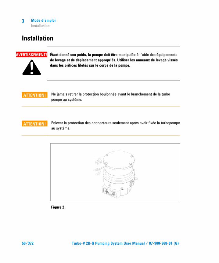
Installation
AVERTISSEMENT!
Étant donné son poids, la pompe doit être manipulée à l’aide des équipements de levage et de déplacement appropriés. Utiliser les anneaux de levage vissés dans les orifices filetés sur le corps de la pompe.
ATTENTION! Ne jamais retirer la protection boulonnée avant le branchement de la turbo pompe au système.
ATTENTION! Enlever la protection des connecteurs seulement après avoir fixée la turbopompe au système.
Figure 2
WA
RN
ING
REMOVE THIS PROTECTION AFTER
MECHANICAL INSTALLATION
NO
CHAMBER
YES

Mode d’emploi Installation
3
Turbo-V 2K-G Pumping System User Manual / 87-900-968-01 (G) 57/372
Ne pas installer et/ou utiliser la pompe dans des milieux exposés aux agents atmosphériques (pluie, gel, neige), à la poussière, aux gaz agressifs ainsi que dans des milieux explosifs ou à fort risque d'incendie.
Pendant le fonctionnement, il est nécessaire de respecter les conditions environnementales suivantes:
� pression maxi: 2 bar au-delà de la pression atmosphérique
� température: de +5°C° à +40°C (Cf. graphique dans "Technical Information")
� humidité relative: 0 – 95 % (non condensante)
En présence de champs magnétiques, la pompe doit être protégée à l'aide d'écrans appropriés. Pour tout autre renseignement, se reporter à l'opuscule "Technical Information".
Le Turbo-V 2K-G doit être connecté à une pompe primaire (Cf. schéma dans "Technical Information").
Le Turbo-V 2K-G peut être installée dans n'importe quelle position.
Le fixer dans une position stable, en reliant la bride d'entrée de la turbopompe à une contre-bride fixe pouvant supporter un couple de serrage de 10600 Nm autour de son axe.
La turbo pompe avec collerette d’entrée ISO doit être fixée à la chambre à vide à l’aide de boulons. Le tableau suivant indique le nombre de boulons nécessaires et le couple de serrage conseillé par Agilent.
Tab. 1
BRIDE TYPE DE COLLIER N. COUPLE DE SERRAGE
ISO 250 F Boulon à filet M10 12 22 Nm

3 Mode d’emploi Installation
58/372 Turbo-V 2K-G Pumping System User Manual / 87-900-968-01 (G)
NOTE La Turbo pompe V 2K-G ne peut être fixée à l’aide de son socle. Le système peut être fixé uniquement à l’aide de sa bride ISO 250F. La fixation doit être réalisée en conformité à la norme ISO 1609. Il est nécessaire d’utiliser des boulons en acier ayant une classe de résistance minimum de 500 N/mm2.
ATTENTION! Le Turbo-V 2K-G appartient à la deuxième catégorie d'installations (ou surtension) prévue par la norme EN 61010-1. De ce fait, brancher le dispositif à une ligne d'alimentation compatible avec cette catégorie. Utiliser les connecteurs fournis pour garantir le niveau de protection IP-54. Le Turbo-V 2K-G dispose de connecteurs pour les en-trées/sorties et pour la communication en série qui doivent être branchés aux circuits extérieurs de façon qu'aucune partie sous tension ne soit accessible.
Pour l'installation des accessoires en option, se reporter à "Technical Information".

Mode d’emploi Utilisation
3
Turbo-V 2K-G Pumping System User Manual / 87-900-968-01 (G) 59/372
Utilisation Ce paragraphe présente les principales procédures opérationnelles.
Avant d'utiliser le système, effectuer tous les branchements électriques et pneumatiques. Pendant le chauffage éventuel de la chambre à vide, la température de la bride d'entrée ne doit pas dépasser 80 °C.
Pendant le fonctionnement de la pompe, la température du rotor ne doit jamais être supérieure à 120 °C.
L'opérateur doit veiller à adapter le mode de fonctionnement au gaz à pomper : 1 pour azote et gaz plus légers, 0 pour Argon (mode défaut). Pour plus de détails, consulter l’appendice "Technical Information".
AVERTISSEMENT!
Ne jamais faire fonctionner la pompe si la bride d'entrée n'est pas reliée à la chambre à vide ou si elle n'est pas fermée avec la bride de fermeture. Eviter de toucher la turbopompe ainsi que ses accessoires éventuels pendant les opérations de chauffage. La température élevée peut être à l'origine de lésions graves.
ATTENTION! Lorsque la turbopompe fonctionne, éviter tout choc, oscillation ou déplacement brusque car les paliers pourraient se détériorer. Pour le refoulement de l'air de la pompe, utiliser de l'air ou du gaz inerte exempt de poussière ou de particules. La pression d'entrée à travers la porte prévue à cet effet doit être inférieure à 1 bar (au-delà de la pression atmosphérique). Pour le pompage de gaz contenant des particules ou des polluants agressifs pour les paliers, ces pompes sont dotées d'une porte spéciale à travers laquelle il est nécessaire de fournir à la pompe un flux de gaz inerte (Azote ou Hélium) pour protéger les paliers (voir l'appendice "Technical Information").

3 Mode d’emploi Utilisation
60/372 Turbo-V 2K-G Pumping System User Manual / 87-900-968-01 (G)
ATTENTION! Ne jamais utiliser la pompe en présence de gaz ou de vapeurs corrosives pouvant endommager les composants internes de la pompe.
AVERTISSEMENT!
Lorsque la pompe est utilisée pour le pompage de gaz toxiques, inflammables ou radioactifs, suivre les procédures typiques de chaque gaz. Ne pas utiliser la pompe en présence de gaz explosifs. La pompe est conçue pour garantir un transfert élevé de l’azote, de l’argon et des gaz plus légers. En cas de pompage de gaz plus lourds que l’argon, contacter le service technique Agilent pour informations.
Utilisation de la pompe Turbo-V 2K-G
Mise en marche du système Avant la mise en marche du système, contrôler que le connecteur E/S soit débranché. Si le système est connecté à un dispositif Entrée/Sortie à distance, s’assurer que le signal de STOP soit activé (voir paragraphe “J1 – REMOTE I/O – [J1 – E/S À DISTANCE”] dans l’appendice "Technical Information").
Pour démarrer le système, effectuer les opérations suivantes :
1 Retirer (si monté) le connecteur E/S.
2 Connecter au réseau.
3 Porter la pression à l’intérieur de la chambre à vide à 0,1 mbar.
4 Donner à la pompe Turbo-V 2K-G le signal de START de l’une des façons suivantes :

Mode d’emploi Utilisation
3
Turbo-V 2K-G Pumping System User Manual / 87-900-968-01 (G) 61/372
a Brancher le connecteur E/S fourni.
b Donner le signal de START à distance à travers le connecteur E/S (Cf. paragraphe "J1 – REMOTE I/O [E/S À DISTANCE]" dans l’appendice "Technical Information").
c Donner le signal de START à distance à travers l’interface sérielle RS 232/485 (Cf. paragraphe "RS 232/485 Communication Description [Description communication]" dans l’appendice "Technical Information").
AVERTISSEMENT!
Lorsque le système est branché au réseau et que le connecteur à 15 broches est connecté, la pompe Turbo-V 2K-G se met automatiquement en marche.
ATTENTION! Le contrôleur est fourni déjà connecté (connexion mécanique et électrique) à la pompe. La séparation du contrôleur du corps de la pompe peut être effectuée uniquement par le personnel autorisé par la société Agilent Vacuum Technologies.
NOTE Lors de la première mise en marche de la pompe Turbo-V 2K-G le contrôleur lance automatiquement le système en exécu-tant une procédure spéciale qui protège les paliers contre tout risque d’endommagement (SOFT START). Le système est lancé progressivement jusqu’à ce qu’il atteigne la vitesse maximum, en un temps qui peut varier de 10 minutes à 1 heure. Dès que le système atteint sa vitesse maximum, la procédure de "soft start" est désactivée et les démarrages suivants sont effectués en mode normal.
3 Mode d’emploi Utilisation
62/372 Turbo-V 2K-G Pumping System User Manual / 87-900-968-01 (G)
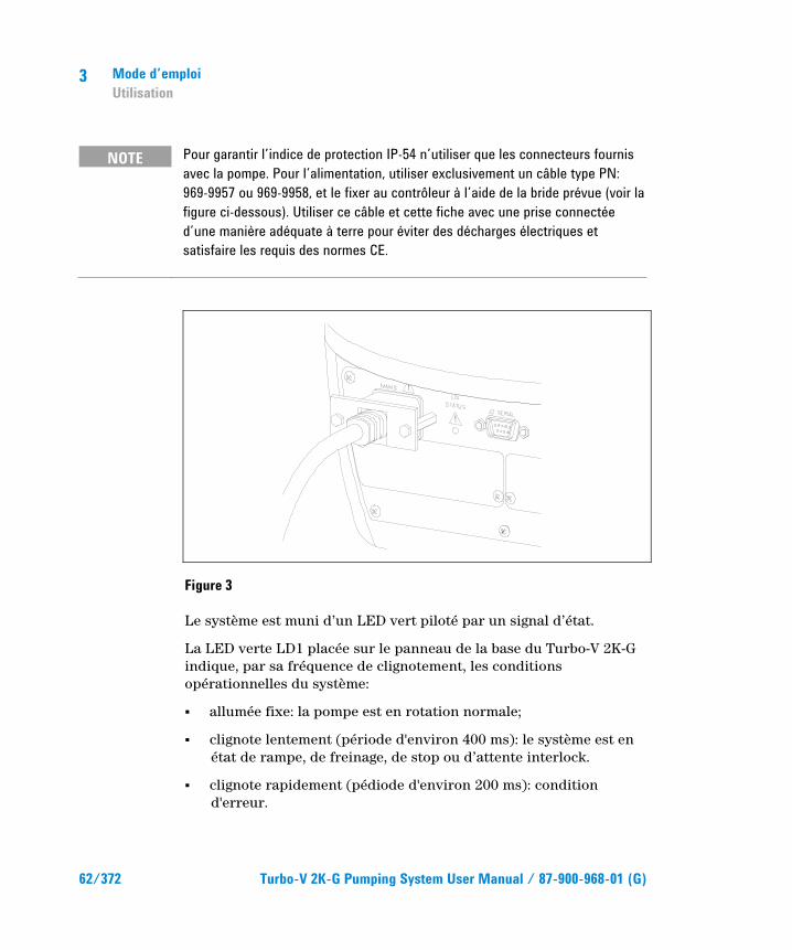
NOTE Pour garantir l’indice de protection IP-54 n’utiliser que les connecteurs fournis avec la pompe. Pour l’alimentation, utiliser exclusivement un câble type PN: 969-9957 ou 969-9958, et le fixer au contrôleur à l’aide de la bride prévue (voir la figure ci-dessous). Utiliser ce câble et cette fiche avec une prise connectée d’une manière adéquate à terre pour éviter des décharges électriques et satisfaire les requis des normes CE.
Figure 3
Le système est muni d’un LED vert piloté par un signal d’état.
La LED verte LD1 placée sur le panneau de la base du Turbo-V 2K-G indique, par sa fréquence de clignotement, les conditions opérationnelles du système:
� allumée fixe: la pompe est en rotation normale;
� clignote lentement (période d'environ 400 ms): le système est en état de rampe, de freinage, de stop ou d’attente interlock.
� clignote rapidement (pédiode d'environ 200 ms): condition d'erreur.

Mode d’emploi Utilisation
3
Turbo-V 2K-G Pumping System User Manual / 87-900-968-01 (G) 63/372
Arrêt du système Pour arrêter la pompe, opérer dans l’un des modes suivants :
1 Débrancher le connecteur E/S.
2 Envoyer un signal de STOP à distance à travers le connecteur E/S (Cf. paragraphe "J1 – REMOTE I/O [E/S À DISTANCE]" dans l’appendice "Technical Information").
3 Envoyer un signal de STOP à distance via l’interface sérielle RS 232/485 (Cf. paragraphe "RS 232/485 Communication Description" dans l’appendice "Technical Information").
Arrêt d’urgence Pour arrêter le Turbo-V 2K-G en conditions d'urgence, il faut débrancher le cordon d'alimentation du contrôleur. Il faut cependant rappeler que cette opération déshabilite non seulement l'alimentation de la pompe mais aussi toutes les autres fonctions du contrôleur comme, par exemple, la gestion de la Purge et du Vent contrôlé, ainsi que la communication avec le système dans lequel la pompe a été intégré via les E/S série ou profibus.
De plus, cette opération ne peut garantir l’arrêt immédiat du rotor dont la vitesse de rotation diminue en fonction du degré de vide présent dans le système.
3 Mode d’emploi Entretien
64/372 Turbo-V 2K-G Pumping System User Manual / 87-900-968-01 (G)
Entretien Le Turbo-V 2K-G n'exige aucun entretien particulier. Toute intervention doit être effectuée par un personnel agréé.
AVERTISSEMENT!
Avant toute intervention sur le système, le débrancher, refouler l'air de la pompe en ouvrant la soupape prévue à cet effet, attendre jusqu'à l'arrêt complet du rotor et jusqu'à ce que la température superficielle de la pompe soit inférieure à 50 °C.
En cas de panne, il est possible de bénéficier du service réparations Agilent ou du "Agilent advanced exchange service" qui permet d'obtenir un système régénéré en remplacement du système endommagé.
NOTE Avant de renvoyer une pompe au constructeur pour réparation ou "advanced exchange service", remplir et faire parvenir au bureau Agilent de votre région la fiche "Sécurité et Santé" jointe au présent manuel d'instructions. Une copie de cette fiche devra être mise dans l'emballage de la pompe avant l'expédition.
En cas de mise au rebut de la pompe, procéder à son élimination conformément aux réglementations nationales concernant la gestion des déchets.
Mode d’emploi Mise au rebut
3
Turbo-V 2K-G Pumping System User Manual / 87-900-968-01 (G) 65/372
Mise au rebut Signification du logo "WEEE" figurant sur les étiquettes. Le symbole ci-dessous est appliqué conformément à la directive CE nommée "WEEE". Ce symbole (unique-ment valide pour les pays de la Communauté euro-péenne) indique que le produit sur lequel il est appliqué NE doit PAS être mis au rebut avec les ordures ména-gères ou les déchets industriels ordinaires, mais passer par un système de collecte sélective. Après avoir vérifié les termes et conditions du contrat de vente, l’utilisateur final est donc prié de contacter le fournisseur du dispositif, maison mère ou revendeur, pour mettre en œuvre le processus de collecte et mise au rebut.

3 Mode d’emploi Mise au rebut
66/372 Turbo-V 2K-G Pumping System User Manual / 87-900-968-01 (G)

Turbo-V 2K-G Pumping System User Manual
67/372
4 Manual de istrucciones Indicaciones de Seguridad para Bombas Turbomoleculares 68 Información general 69 Almacenamiento 71 Preparación para la instalación 72 Instalación 74 Uso 77 Uso de Turbo-V 2K-G 78 Cómo poner en funcionamiento el sistema 78 Cómo detener la Turbo-V 2K-G 81 Parada de Emergencia 81 Mantenimiento 82 Eliminación 83 Traducción de las instrucciones originales
4 Manual de istrucciones Indicaciones de Seguridad para Bombas Turbomoleculares
68/372 Turbo-V 2K-G Pumping System User Manual / 87-900-968-01 (G)
Indicaciones de Seguridad para Bombas Turbomoleculares
Las bombas Turbomoleculares descritas en el siguiente manual de instrucciones tienen una elevada cantidad de energía cinética debido a la alta velocidad de rotación en combinación a la masa específica de sus rotores.
En el caso de un daño del sistema, por ejemplo por un contacto entre el rotor y el estator o por una rotura del rotor, la energía de rotación podría ser liberada.
¡ADVERTENCIA!
Para evitar daños a los equipos y prevenir lesiones a los operadores, es necesario seguir atentamente las instrucciones de instalación descritas en el presente manual!

Manual de istrucciones Información general
4
Turbo-V 2K-G Pumping System User Manual / 87-900-968-01 (G) 69/372
Información general Este equipo es para uso profesional. El usuario ha de leer atentamente el presente manual de instrucciones y cualquier otra información suplementaria facilitada por Agilent antes de usar el aparato. Agilent se considera libre de posibles responsabilidades debidas al incumplimiento total o parcial de las instrucciones, al uso impropio por parte de personal no preparado, a operaciones no autorizadas o a un uso contrario a las normas nacionales específicas.
El sistema está en condiciones de bombear diferentes tipos de gas y de compuestos gaseosos pero no es adecuado para bombear líquidos ni partículas sólidas.
El efecto de bombeo se obtiene mediante una turbina rotativa de alta velocidad (33000 r.p.m. máx.) movida por un motor eléctrico trifásico de alto rendimiento. El Turbo-V 2K-G no posee ningún agente contaminante y por lo tanto es adecuado para aplicaciones que requieren un vacío’ “limpio”.
Además cuenta con conectores auxiliares mediante los cuales es posible pilotearlo de remoto a través de un ordenador host conectado con línea serie (RS232 o RS485).
A continuación se facilita toda la información necesaria para garantizar la seguridad del operador al usar el aparato. En el anexo “Technical Information” se facilita información más detallada.
4 Manual de istrucciones Información general
70/372 Turbo-V 2K-G Pumping System User Manual / 87-900-968-01 (G)
Este manual utiliza los símbolos convencionales siguientes:
¡ADVERTENCIA!
Los mensajes de advertencia atraen la atención del operador sobre un procedimiento o una operación específica que, al no realizarse correctamente, podría provocar graves lesiones personales.
¡ATENCIÓN! Los mensajes de atención se visualizan antes de procedimientos que, al no respetarse, podrían provocar daños al equipo.
NOTA Las notas contienen información importante extraída del texto.

Manual de istrucciones Almacenamiento
4
Turbo-V 2K-G Pumping System User Manual / 87-900-968-01 (G) 71/372
Almacenamiento Para garantizar el nivel máximo de funcionalidad y fiabilidad de las bombas turbomoleculares Agilent, deberán aplicarse las siguientes instrucciones:
� durante el transporte, desplazamiento y almacenamiento de las bombas no deberán superarse las siguientes condiciones ambientales:
� temperatura: entre –20 °C y 70 °C;
� humedad relativa: entre 0 y 95 % (no condensante);
� el cliente deberá activar siempre las bombas turbomoleculares en modalidad Soft-Start al recibirlas y ponerlas en funcionamiento por primera vez;
� el período máximo de almacenamiento de una bomba turbomolecular es de diez meses a contar de la fecha de envío al cliente.
¡ATENCIÓN! En caso de superarse por cualquier motivo el período máximo permitido de almacenamiento, será necesario devolver la bomba al fabricante. Para mayores informaciones al respecto, se ruega contactar con el representante local de Agilent.

4 Manual de istrucciones Preparación para la instalación
72/372 Turbo-V 2K-G Pumping System User Manual / 87-900-968-01 (G)
Preparación para la instalación El Turbo-V 2K-G se suministra en un embalaje especial de protección; si se observan daños, que podrían haberse producido durante el transporte, ponerse en contacto con la oficina local de ventas.
Durante la operación de desembalaje, tener cuidado de que no se caiga el Turbo-V 2K-G y de no someterlo a golpes o vibraciones.
Quitar la protección de los conectores solamente después de haber fijado al sistema la turbobomba.
Debido a su peso (35 kg) para extraer la bomba del embalaje deben utilizarse las tres armellas en 120° que se encuentran enroscadas en el cuerpo bomba.
No abandonar el embalaje en el medio ambiente. El material es completamente reciclable y cumple con la directiva CEE 85/399 para la preservación del medio ambiente.
¡ATENCIÓN! Para evitar problemas de desgasificación, no tocar con las manos desnudas los componentes destinados a exponerse al vacío. Utilizar siempre guantes u otra protección adecuada.
NOTA La Turbo-V 2K-G no puede sufrir daños sólo por quedar expuesta a la acción de la atmósfera. No obstante, se aconseja mantener la bomba cerrada y sellada hasta el momento de instalarla en el sistema a fin de prevenir la contaminación del mismo.
Manual de istrucciones Preparación para la instalación
4
Turbo-V 2K-G Pumping System User Manual / 87-900-968-01 (G) 73/372
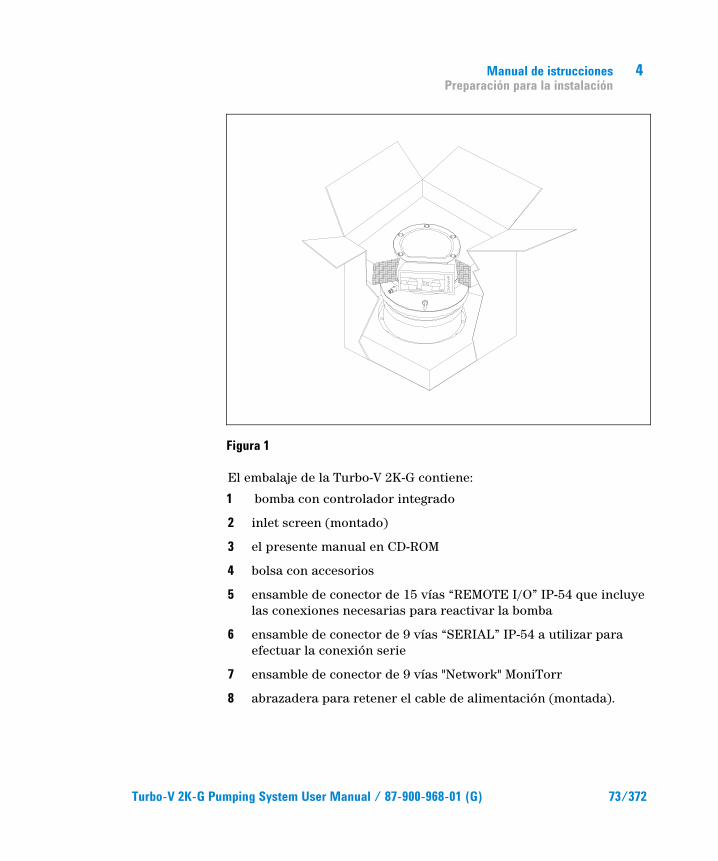
Figura 1
El embalaje de la Turbo-V 2K-G contiene:
1 bomba con controlador integrado
2 inlet screen (montado)
3 el presente manual en CD-ROM
4 bolsa con accesorios
5 ensamble de conector de 15 vías “REMOTE I/O” IP-54 que incluye las conexiones necesarias para reactivar la bomba
6 ensamble de conector de 9 vías “SERIAL” IP-54 a utilizar para efectuar la conexión serie
7 ensamble de conector de 9 vías "Network" MoniTorr
8 abrazadera para retener el cable de alimentación (montada).
4 Manual de istrucciones Instalación
74/372 Turbo-V 2K-G Pumping System User Manual / 87-900-968-01 (G)
Instalación
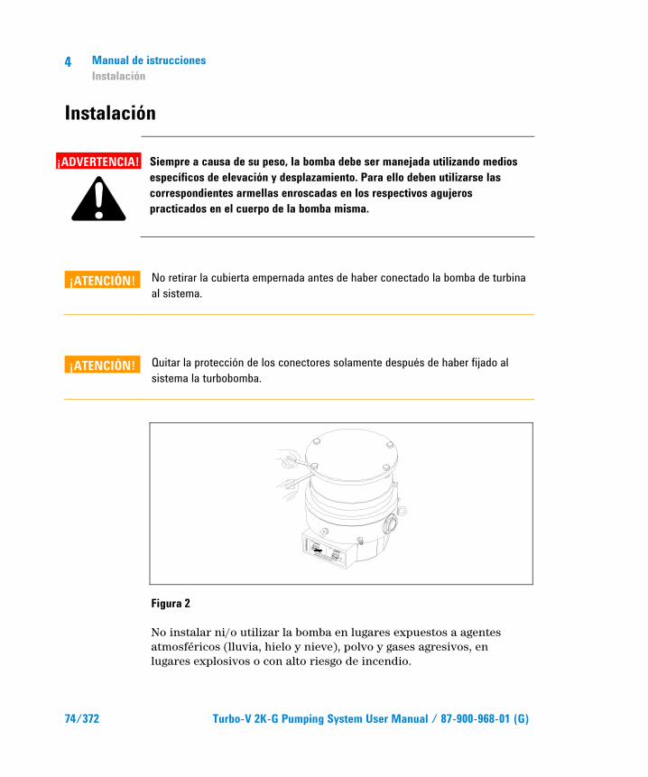
¡ADVERTENCIA!
Siempre a causa de su peso, la bomba debe ser manejada utilizando medios específicos de elevación y desplazamiento. Para ello deben utilizarse las correspondientes armellas enroscadas en los respectivos agujeros practicados en el cuerpo de la bomba misma.
¡ATENCIÓN! No retirar la cubierta empernada antes de haber conectado la bomba de turbina al sistema.
¡ATENCIÓN! Quitar la protección de los conectores solamente después de haber fijado al sistema la turbobomba.
Figura 2
No instalar ni/o utilizar la bomba en lugares expuestos a agentes atmosféricos (lluvia, hielo y nieve), polvo y gases agresivos, en lugares explosivos o con alto riesgo de incendio.
WA
RN
ING
REMOVE THIS PROTECTION AFTER
MECHANICAL INSTALLATION
NO
CHAMBER
YES

Manual de istrucciones Instalación
4
Turbo-V 2K-G Pumping System User Manual / 87-900-968-01 (G) 75/372
Durante el funcionamiento es necesario que se respeten las condiciones ambientales siguientes:
� presión máxima: 2 bares por encima de la presión atmosférica
� temperatura: de +5ºC a +40ºC (véase gráfico en el anexo “Technical Information”)
� humedad relativa: 0-95% (no condensadora).
Cuando existan campos electromagnéticos, la bomba ha de protegerse mediante pantallas oportunas. Véase el anexo “Technical Information” para más detalles.
El Turbo-V 2K-G ha de conectarse a una bomba primaria (véase diagrama en “Technical Information”).
El Turbo-V 2K-G puede instalarse en cualquier posición. Fijar el Turbo-V 2K-G en posición estable conectando la brida de entrada de la turbobomba a una contrabrida fija que puede resistir a un par de 10600 Nm alrededor de su eje.
La bomba de turbina con brida de entrada ISO debe fijarse por medio de pernos a la cámara de vacío. En la siguiente tabla se indican el número de pernos necesarios y el par de apriete aconsejado por Agilent para fijarlos.
Tab. 1
BRIDA TIPO DE MORDAZA N. PAR DE APRIETE
ISO 250 F Perno con rosca M10 12 22 Nm
NOTA La Turbo-V 2K-G no puede ser fijada por medio de su base. En efecto, el sistema puede fijarse únicamente mediante su brida ISO 250F. La fijación debe realizarse de conformidad con lo establecido por la norma ISO 1609. Deben utilizarse pernos de acero cuya clase de resistencia sea de al menos 500 N/mm2.
4 Manual de istrucciones Instalación
76/372 Turbo-V 2K-G Pumping System User Manual / 87-900-968-01 (G)
¡ATENCIÓN! El Turbo-V 2K-G pertenece a la segunda categoría de instalación (o sobretensión) prevista por la normativa EN 61010-1. Por lo tanto este dispositivo debe ser conectado a una línea de alimentación adecuada para dicha categoría. Para garantizar el aislamiento IP-54 deben utilizarse los ensambles de conectores suministrados adjuntos. El Turbo-V 2K-G tiene conectores para las entradas/salidas y para la comunicación serial que deben ser conectados a los circuitos externos de manera que ninguna parte bajo tensión quede accesible. Controlar que el aislamiento del dispositivo conectado al Turbo-V 2K-G mantenga una acción aisladora incluso en caso de verificarse una avería, de conformidad con lo establecido por la normativa EN 61010-1.
Para instalar los accesorios opcionales, véase “Technical Information”.
Manual de istrucciones Uso
4
Turbo-V 2K-G Pumping System User Manual / 87-900-968-01 (G) 77/372
Uso En este apartado se citan los procedimientos operativos principales. Antes de usar el sistema realizar todas las conexiones eléctricas y neumáticas. Durante el posible calentamiento de la cámara de vacío, la temperatura de la brida de entrada no ha de ser superior a 80 °C.
Durante el funcionamiento de la bomba la temperatura del rotor no deberá superar nunca los 120 °C.
El operador deberá verificar siempre que el modo de funcionamiento que ha predispuesto sea adecuado para el gas que se debe bombear, esto es: 1 para nitrógeno y gases más ligeros, 0 para argón (modo predeterminado). Para mayores detalles véase el apéndice "Technical Information".
¡ADVERTENCIA!
No hacer funcionar nunca la bomba si la brida de entrada no está conectada al sistema o no está cerrada con la brida de cierre. No tocar la turbobomba y sus posibles accesorios durante las operaciones de calentamiento. La alta temperatura puede provocar lesiones a las personas.
¡ATENCIÓN! Evítense golpes, oscilaciones o bruscos desplazamientos de la turbobomba durante su funcionamiento. Los cojinetes podrían dañarse. Para el envío de aire de la bomba utilizar aire o gas inerte sin polvo o partículas. La presión de entrada a través de la puerta deberá ser inferior a 1 bar (por encima de la presión atmosférica). Para bombear gases con partículas o contaminantes agresivos para los cojinetes estas bombas están dotadas de una puerta específica mediante la cual es necesario suministrar a la bomba un caudal de gas inerte (Nitrógeno o Helio) para proteger los rodamientos (véase el anexo “Technical Information”).

4 Manual de istrucciones Uso
78/372 Turbo-V 2K-G Pumping System User Manual / 87-900-968-01 (G)
¡ATENCIÓN! Nunca usar la bomba en presencia de gases o vapores corrosivos que puedan dañar los materiales del interior de la bomba.
¡ADVERTENCIA!
Cuando la bomba se utiliza para bombear gases tóxicos, inflamables o radioactivos, seguir los procedimientos apropiados típicos de cada gas. No usar la bomba cuando haya gases explosivos. La bomba ha sido proyectada para una elevada transferencia de nitrógeno, argón y gases más ligeros. En caso de que deban bombearse gases más pesados que el argón se ruega tomar contacto con la Asistencia Técnica de Agilent a fin de recibir mayores informaciones.
Uso de Turbo-V 2K-G
Cómo poner en funcionamiento el sistema Antes de activar el sistema deberá retirarse el ensamble conector I/O. Si el sistema se encuentra conectado a un dispositivo de Input/Output remoto, verificar que la señal de STOP esté activada (véase el apartado "J1 – REMOTE I/O" en el apéndice "Technical Information").
Para poner en funcionamiento del sistema se deberá proceder de la manera que a continuación se indica:
1 retirar (si está presente) el ensamble conector I/O;
2 conectar la alimentación de red;
3 disponer en 0,1 mbar la presión en el interior de la cámara de vacío;
4 dar la señal de START a la Turbo-V 2K-G mediante una de las siguientes formas:
a conectar el ensamble conector I/O suministrado adjunto;

Manual de istrucciones Uso
4
Turbo-V 2K-G Pumping System User Manual / 87-900-968-01 (G) 79/372
b dar la señal de START de remoto mediante el conector I/O (véase el apartado "J1 – REMOTE I/O" en el apéndice "Technical Information");
c dar la señal de START de remoto mediante la interfaz serie RS 232/485 (véase el apartado "RS 232/485 Communication Description" en el apéndice "Technical Information").
¡ADVERTENCIA!
Una vez que se conecta la alimentación y se activa el ensamble conector de 15 pins suministrado adjunto, la Turbo-V 2K-G parte automáticamente.
¡ATENCIÓN! El controlador se entrega ya conectado mecánica y eléctricamente a la bomba. La separación del controlador respecto del cuerpo de la bomba puede ser efectuada únicamente por personal autorizado por Agilent Vacuum Technologies.
NOTA Al activar la Turbo-V 2K-G por primera vez, el controlador activa automáticamente el sistema mediante un procedimiento especial que protege los cojinetes contra posibles daños (SOFT START). El sistema se activa paso a paso hasta alcanzar la plena velocidad, en un lapso comprendido entre 10 minutos y 1 hora. Una vez que el sistema ha alcanzado plena velocidad, el procedimiento de "soft start" se inhabilita y las sucesivas activaciones se efectúan de modo normal.

4 Manual de istrucciones Uso
80/372 Turbo-V 2K-G Pumping System User Manual / 87-900-968-01 (G)
NOTA Al activar la Turbo-V 2K-G por primera vez, el controlador activa automáticamente el sistema mediante un procedimiento especial que protege los cojinetes contra posibles daños (SOFT START). El sistema se activa paso a paso hasta alcanzar la plena velocidad, en un lapso comprendido entre 10 minutos y 1 hora. Una vez que el sistema ha alcanzado plena velocidad, el procedimiento de "soft start" se inhabilita y las sucesivas activaciones se efectúan de modo normal.
Figura 3
El sistema cuenta con un LED verde piloteado por una señal de estado. El LED verde LD1 situado en el panel de la base del TURBO-V 2K-G indica, con la frecuencia de su parpadeo, las condiciones operativas del sistema:
� encendido fijo: la bomba está en rotación normal;
� parpadea lentamente (periodo de 400 ms aproximadamente): el sistema está en estado de rampa, o de frenado, o de stop, o de “waiting for iterlock”
� parpadea rápidamente (periodo de 200 ms aproximadamente): condición de error.

Manual de istrucciones Uso
4
Turbo-V 2K-G Pumping System User Manual / 87-900-968-01 (G) 81/372
Cómo detener la Turbo-V 2K-G La detención de la bomba podrá efectuarse aplicando una de las siguientes modalidades:
1 retirando el ensamble conector de I/O suministrado adjunto;
2 enviando una señal de STOP de remoto mediante el conector I/O (véase el apartado "J1 – REMOTE I/O" en el apéndice "Technical Information");
3 enviando una señal de STOP de remoto mediante el interfaz serie RS 232/485 (véase el apartado "RS 232/485 Communication Description" en el apéndice "Technical Information").
Parada de Emergencia Para detener en condiciones de emergencia el Turbo-V 2K-G es necesario desconectar del controlador el cable de alimentación. De todas maneras, se debe tener en cuenta que esta operación además de inhabilitar completamente la alimentación de la bomba, inhabilita todas las otras funciones del controller como por ejemplo la gestión del Purge y del Vent Controlado y, la capacidad de comunicarse con el sistema en el que la bomba se integró mediante I/Os, Serial o Profibus.
Además, esta operación no puede garantizar la parada inmediata del rotor cuya velocidad de rotación disminuirá en función del grado de vacío presente en el sistema.
4 Manual de istrucciones Mantenimiento
82/372 Turbo-V 2K-G Pumping System User Manual / 87-900-968-01 (G)
Mantenimiento El TV 301 Navigator no necesita ningún mantenimiento. Cualquier operación deberá ser realizada por personal autorizado.
¡ADVERTENCIA!
Antes de realizar cualquier operación en el sistema desconectarlo de la corriente, enviar aire de la bomba abriendo la válvula oportuna, esperar hasta que el rotor se pare completamente y esperar a que la temperatura superficial de la bomba sea inferior a 50 ºC.
En caso de avería se podrá utilizar el servicio de reparación Agilent o el “Agilent advanced exchange service”, que permite obtener un sistema regenerado para sustituir el averiado.
NOTA Antes de enviar al fabricante un sistema para su reparación o “advanced exchange service”, es imprescindible cumplimentar y remitir a la oficina local de ventas la ficha de “Seguridad y Salud” adjunta al presente manual de instrucciones. Una copia de la misma se deberá introducir en el embalaje del sistema antes de enviarlo.
En caso de que el sistema se tenga que desguazar, eliminarlo respetando las normas nacionales específicas.
Manual de istrucciones Eliminación
4
Turbo-V 2K-G Pumping System User Manual / 87-900-968-01 (G) 83/372
Eliminación Significado del logotipo "WEEE" presente en las etiquetas. El símbolo que se indica a continuación, es aplicado en observancia de la directiva CE denominada "WEEE". Este símbolo (válido sólo para los países miembros de la Comunidad Europea) indica que el producto sobre el cual ha sido aplicado, NO debe ser eliminado junto con los residuos comunes sean éstos domésticos o industriales, y que, por el contrario, deberá ser sometido a un procedimiento de recogida diferenciada. Por lo tanto, se invita al usuario final, a ponerse en contacto con el proveedor del dispositivo, tanto si éste es la casa fabricante o un distribuidor, para poder proveer a la recogida y eliminación del producto, después de haber efectuado una verificación de los términos y condiciones contractuales de venta.
4 Manual de istrucciones Eliminación
84/372 Turbo-V 2K-G Pumping System User Manual / 87-900-968-01 (G)

Turbo-V 2K-G Pumping System User Manual
85/372
5 Manual de Istruções Indicações de Segurança para Bombas Turbomoleculares 86 Informações gerais 87 Armazenagem 89 Preparação para a instalação 90 Instalação 92 Utilização 95 Uso da Turbo-V 2K-G 96 Como activar o sistema 96 Como parar a Turbo-V 2K-G 99 Paragem de Emergência 99 Manutenção 100 Eliminação 101 Tradução das instruções originais
5 Manual de Istruções Indicações de Segurança para Bombas Turbomoleculares
86/372 Turbo-V 2K-G Pumping System User Manual / 87-900-968-01 (G)
Indicações de Segurança para Bombas Turbomoleculares
As bombas turbomoleculares descritas no seguinte Manual de Instruções têm uma alta quantidade de energia cinética devida à alta velocidade de rotação unida à massa específica de seus rotores.
Em caso de avaria do sistema, causada, por exemplo, por um contacto entre o rotor e o estator ou uma ruptura do rotor, a energia de rotação poderia ser liberada.
ATENÇAO!
Para evitar danos à aparelhagem e prevenir lesões aos operadores, é necessário seguir atentamente as instruções de instalação descritas neste manual!
Manual de Istruções Informações gerais
5
Turbo-V 2K-G Pumping System User Manual / 87-900-968-01 (G) 87/372
Informações gerais Esta aparelhagem destina-se a uso profissional. O utilizador deve ler atentamente o presente manual de instruções e todas as informações adicionais fornecidas pela Agilent antes de utilizar a aparelhagem. A Agilent não se responsabiliza pela inobservância total ou parcial das instruções, pelo uso indevido por parte de pessoas não treinadas, por operações não autorizadas ou pelo uso contrário às normas nacionais específicas.
O Turbo-V 2K-G é um sistema integrado, constituído por uma bomba turbomolecular para aplicações de alto e ultra-alto vácuo, integrada no relativo controller.
O sistema está em condições de bombear muitos tipos de gases ou de compostos gasosos, mas não é adequado para aspirar líquidos ou partículas sólidas.
O efeito da bomba é obtido através de uma turbina rotativa de alta velocidade (33000 r.p.m. máx.) movida por um motor eléctrico trifásico de alto rendimento. O Turbo-V 2K-G é totalmente isentos de agentes contaminadores e, portanto, é adequado para aplicações que requerem um vácuo "limpo".
Além disso, está equipado com conectores auxiliares com os quais é possível comandá-lo à distância através de um computador host ligado com linha série (RS232 ou RS485).
Nos seguintes parágrafos estão descritas todas as informações necessárias para garantir a segurança do operador durante o uso da aparelhagem. Informações detalhadas são fornecidas no apêndice "Technical Information".

5 Manual de Istruções Informações gerais
88/372 Turbo-V 2K-G Pumping System User Manual / 87-900-968-01 (G)
Este manual utiliza as seguintes convenções:
ATENÇAO!
As mensagens de atenção chamam a atenção do operador para um procedimento ou uma prática específica que, se não efectuada correctamente, pode provocar graves lesões pessoais.
CUIDADO! As mensagens de cuidado são visualizadas antes de procedimentos que, se não observados, podem causar danos à aparelhagem.
NOTA As notas contêm informações importantes destacadas do texto.

Manual de Istruções Armazenagem
5
Turbo-V 2K-G Pumping System User Manual / 87-900-968-01 (G) 89/372
Armazenagem Para garantir o nível Máximo de funcionalidade e fiabilidade das bombas Turbomoleculares Agilent, devem ser observadas as seguintes prescrições:
� durante o transporte, o deslocamento e a armazenagem das bombas as condições ambientais devem ser as seguintes:
� temperatura: de –20 °C a 70 °C
� umidade relativa: de 0 a 95 % (não condensante)
� ao acionar as bombas turbomoleculares pela primeira vez, o cliente deve ativá-las sempre em modalidade Soft-Start
� o tempo máximo de armazenagem de uma bomba turbomolecular é de 10 meses a contar da data da expedição
CUIDADO! Se, por uma razão qualquer, o período de armazenagem for superior, será necessário enviar outra vez a bomba para o fabricante. Para mais informações, contatar o representante local da Agilent.
5 Manual de Istruções Preparação para a instalação
90/372 Turbo-V 2K-G Pumping System User Manual / 87-900-968-01 (G)
Preparação para a instalação O Turbo-V 2K-G é fornecido numa embalagem protectora especial; se esta apresentar sinais de danos, que poderiam ter ocorrido durante o transporte, entrar em contacto com o escritório de vendas local.
Durante a remoção da embalagem, tomar muito cuidado para não deixar cair o controller e para não submetê-lo a choques ou vibrações.
Retirar a protecção dos conectores somente depois que a turbobomba estiver fixada ao sistema.
Devido ao seu peso (35 kg), para retirar a bomba da embalagem é necessário utilizar as três cavilhas fixadas a 120° ao corpo da bomba.
Não depositar a embalagem no meio ambiente. O material é completamente reciclável e em conformidade com a norma CEE 85/399 para a protecção do meio ambiente.
CUIDADO! Para evitar problemas de perdas de gás, não tocar com as mãos os componentes destinados à exposição do vácuo. Utilizar sempre luvas ou outra protecção adequada.
NOTA A normal exposição ao ar não pode danificar a Turbo-bomba V-2k. Aconselha-se, no entanto, mantê-la selada e bem fechada dentro da caixa até ao momento da instalação no sistema, para evitar que se suje com poeiras.

Manual de Istruções Preparação para a instalação
5
Turbo-V 2K-G Pumping System User Manual / 87-900-968-01 (G) 91/372
Figura 1
A embalagem da Turbo-V 2K-G contém:
1 bomba com controller integrado
2 inlet screen (montado)
3 este manual em CD-ROM
4 sacos dos acessórios
5 conector conjugado de 15 vias “REMOTE I/O” IP-54 com todas as ligações necessárias para activar a bomba.
6 conector conjugado de 9 vias “SERIAL” IP-54 a utilizar para a ligação série
7 conector conjugado de 9 vias "Network" MoniTorr
8 braçadeira de fixação do cabo de alimentação (montada).

5 Manual de Istruções Instalação
92/372 Turbo-V 2K-G Pumping System User Manual / 87-900-968-01 (G)
Instalação
ATENÇAO!
Devido ao seu peso, a bomba deve ser manuseada com a ajuda de equipamentos de levantamento e deslocação específicos. Para tal, utilizar as respectivas cavilhas montadas nos furos roscados existentes no corpo da bomba.
CUIDADO! Não remover a cobertura aparafusada antes de ligar a turbobomba ao sistema.
CUIDADO! Retirar a protecção dos conectores somente depois que a turbobomba estiver fixada ao sistema.
Figura 2
Não instalar e/ou usar a bomba em ambientes expostos a agentes atmosféricos (chuva, gelo, neve), poeiras, gases agressivos, em ambientes com possibilidade de explosão ou com elevado risco de incêndio.
WA
RN
ING
REMOVE THIS PROTECTION AFTER
MECHANICAL INSTALLATION
NO
CHAMBER
YES

Manual de Istruções Instalação
5
Turbo-V 2K-G Pumping System User Manual / 87-900-968-01 (G) 93/372
Durante o funcionamento é necessário que sejam respeitadas as seguintes condições ambientais:
� pressão máxima: 2 bar além da pressão atmosférica
� temperatura: de + 5ºC a + 40ºC (consultar a planilha no apêndice “Technical Information”)
� humidade relativa: 0 - 95% (não condensante).
Na presença de campos electromagnéticos, a bomba deve ser protegida através de blindagens adequadas. Para ulteriores detalhes, consultar o apêndice "Technical Information".
O Turbo-V 2K-G deve ser ligado a uma bomba primária (consultar esquema em "Technical Information").
O Turbo-V 2K-G pode ser instalado em qualquer posição. Fixar o Turbo-V 2K-G em posição estável ligando o flange de entrada da turbobomba a um contra-flange fixo capaz de resistir a um torque de 10600 Nm ao redor do próprio eixo.
A turbobomba com flange de entrada ISO deve ser fixada à câmara de vácuo através de parafusos. Damos a seguir uma tabela com o número de parafusos necessários e o tipo de torque de aperto aconselhados pela Agilent.
Tab. 1
FLANGE TIPO DE BORNE N TORQUE DE APERTO
ISO 250 F Parafuso com rosca M10. 12 22 Nm
NOTA A Turbo-V 2K-G não pode ser fixada por meio da sua base. O sistema pode ser segurado só por intermédio da sua flange ISO 250F. A fixação deve ser realizada de acordo com o estabelecido na norma ISO 1609. Devem ser utilizados parafusos de aço com uma classe de resistência de pelo menos 500 N/mm2.

5 Manual de Istruções Instalação
94/372 Turbo-V 2K-G Pumping System User Manual / 87-900-968-01 (G)
CUIDADO! O Turbo-V 2K-G pertence à segunda categoria de instalação (ou sobretensão) prevista pela norma NE 61010-1. Portanto, ligue o dispositivo a uma linha de alimentação apropriada para esta categoria. Utilizar os conectores conjugados fornecidos de série para garantir o isolamento IP-54. O Turbo-V 2K-G tem dois conectores para as entradas/saídas e para a comunicação de série que devem ser ligados aos circuitos externos de modo a não permitir o acesso às partes sob tensão. Assegure-se de que o isolamento do dispositivo ligado ao Turbo-V 2K-G esteja isolado correctamente mesmo em caso de avaria, conforme previsto pela norma NE 61010-1.
Para a instalação dos acessórios opcionais, consultar "Technical Information".

Manual de Istruções Utilização
5
Turbo-V 2K-G Pumping System User Manual / 87-900-968-01 (G) 95/372
Utilização Neste parágrafo são descritos os principais procedimentos operacionais. Antes de usar o sistema, efectuar todas as ligações eléctricas e pneumáticas. Durante o eventual aquecimento da câmara a vácuo, a temperatura no flange de entrada não deve ser superior a 80 °C. Durante o funcionamento da bomba a temperatura do rotor deve ser sempre inferior a 120 °C.
O operador deve verificar se o aparelho funciona na modalidade correcta, de acordo com o tipo de gás aspirado: 1 para Azoto e gases mais leves. 0 para Argon (modalidade pré-definida). Para maiores detalhes, consultar o apêndice “Technical Information”.
ATENÇAO!
Nunca activar a bomba se o flange de entrada não estiver ligado à câmara de vácuo ou não estiver fechado com o flange de fecho. Não tocar a turbobomba e os seus eventuais acessórios durante as operações de aquecimento. A elevada temperatura pode causar lesões às pessoas.
CUIDADO! Evitar colisões, oscilações ou deslocamentos bruscos da turbobomba quando está a funcionar. Os rolamentos poderiam sofrer danos. Para a saída de ar da bomba utilizar ar ou gás inerte sem poeiras ou partículas. A pressão de entrada através da porta específica deve ser inferior a 1 bar (acima da pressão atmosférica). Para bombear gases que contenham partículas ou poluentes daninhos para os rolamentos, estas bombas estão equipadas com uma porta específica através da qual é necessário fornecer à bomba um fluxo de gás inerte (Azoto ou Hélio) para proteger os rolamentos (consultar o apêndice "Technical Information”).

5 Manual de Istruções Utilização
96/372 Turbo-V 2K-G Pumping System User Manual / 87-900-968-01 (G)
CUIDADO! Jamais usar a bomba na presença de gases ou vapores corrosivos que possam danificar os materiais no interior da bomba.
ATENÇAO!
Quando a bomba é utilizada para bombear gases tóxicos, inflamáveis ou radioactivos, seguir os procedimentos adequados típicos para cada gás. Não usar a bomba na presença de gases explosivos. A bomba foi concebida para fornecer um elevado caudal de Azoto, Argon e gases mais leves. Se houver a necessidade de bombear gases mais pesados que o Argon, aconselha-se a entrar em contacto com a Assistência Técnica da Agilent para obter maiores informações.
Uso da Turbo-V 2K-G
Como activar o sistema Antes do arranque do sistema, assegurar-se de que o conector conjugado I/O não está montado. Se o sistema está ligado a um dispositivo de Input/Output remoto, assegurar-se de que o sinal de STOP está activo (consultar o parágrafo “J1 - REMOTE I/O” no apêndice “Technical Information”).
Para activar o sistema, executar as seguintes operações:
1 remover (se presente) o conector conjugado I/O
2 ligar o cabo à rede de alimentação eléctrica.
3 deixar aumentar a pressão dentro da câmara de vácuo até atingir 0,1 mbars.
4 fornecer à Turbo-V 2K-G o sinal de START num dos seguintes modos:
Manual de Istruções Utilização
5
Turbo-V 2K-G Pumping System User Manual / 87-900-968-01 (G) 97/372
a ligar o conector conjugado I/O fornecido de série.
b dar o comando remoto de START utilizando o conector I/O (consultar o parágrafo “J1 - REMOTE I/O” no apêndice “Technical Information”).
c dar o comando remoto de START utilizando o interface série RS 232/485 (consultar o parágrafo “RS 232/485 Communication Description” no apêndice “Technical Information”).
ATENÇAO!
Quando o aparelho está ligado à rede de alimentação eléctrica e o conector conjugado de 15 pinos, fornecido de série, está introduzido, a Turbo-V 2K-G activa-se automaticamente.
CUIDADO! O controller é fornecido com todas as ligações mecânicas e as conexões eléctricas com a bomba já instaladas. O controller pode ser separado do corpo da bomba exclusivamente por pessoal autorizado pela Agilent Vacuum Techmologies.
NOTA Quando se activa a Turbo-V 2K-G pela primeira vez, o controller activa automaticamente o sistema com um processo especial que protege os mancais contra possíveis danos (SOFT START). O sistema entra em funcionamento com uma sequência de operações sucessivas, até atingir o regime máximo num intervalo de tempo que oscila entre 10 minutos e 1 hora. Depois de o sistema chegar à velocidade de regime máxima, o processo de “soft start” é desabilitado e os arranques posteriores realizam-se na modalidade normal.
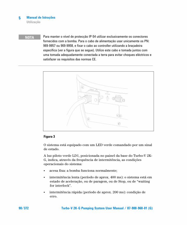
5 Manual de Istruções Utilização
98/372 Turbo-V 2K-G Pumping System User Manual / 87-900-968-01 (G)
NOTA Para manter o nível de protecção IP-54 utilizar exclusivamente os conectores fornecidos com a bomba. Para o cabo de alimentação usar unicamente os PN: 969-9957 ou 969-9958, e fixar o cabo ao controller utilizando a braçadeira específica (ver a figura que se segue). Utilize este cabo e tomada juntos com uma tomada adequadamente conectada a terra para evitar choques eléctricos e satisfazer os requisitos das normas CE.
Figura 3
O sistema está equipado com um LED verde comandado por um sinal de estado.
A luz piloto verde LD1, posicionada no painel da base do Turbo-V 2K-G, indica, através da frequência de intermitência, as condições operacionais do sistema:
� acesa fixa: a bomba funciona normalmente;
� intermitência lenta (período de aprox. 400 ms): o sistema está em estado de aceleração, ou de paragem, ou de Stop, ou de “waiting for interlock”.
� intermitência rápida (período de aprox. 200 ms): condição de erro.

Manual de Istruções Utilização
5
Turbo-V 2K-G Pumping System User Manual / 87-900-968-01 (G) 99/372
Como parar a Turbo-V 2K-G Para parar a bomba é possível utilizar um dos seguintes métodos:
1 retirando o conector conjugado de I/O fornecido de série.
2 dando o comando remoto de STOP através do conector I/O (consultar o parágrafo “J1 - REMOTE I/O” no apêndice “Technical Information”).
3 dando um comando remoto de STOP através do interface série RS 232/485 (consultar o parágrafo “RS 232/485 Communication Description” no apêndice “Technical Information”).
Paragem de Emergência Para parar o Turbo-V 2K-G em condições de emergência é necessário desligar, do controller, o cabo de alimentação. É preciso ter em conta que esta operação além de desabilitar completamente a alimentação da bomba desabilita também todas as outras funções do controller, como por exemplo a gestão do Purge e do Vent Controlado, e a capacidade de comunicar-se com o sistema no qual a bomba foi integrada via I/Os, Serial ou Profibus.
Além disso, esta operação não pode garantir a paragem imediata do rotor cuja velocidade de rotação diminuirá em função do grau de vácuo presente no sistema.
5 Manual de Istruções Manutenção
100/372 Turbo-V 2K-G Pumping System User Manual / 87-900-968-01 (G)
Manutenção O TV 301 Navigator não requer qualquer manutenção. Todas as operações devem ser efectuadas por pessoal autorizado.
ATENÇAO!
Antes de executar qualquer operação no sistema, desligá-lo da alimentação, introduzir ar na bomba abrindo a válvula específica, aguardar até a completa paragem do rotor e até que a temperatura superficial da bomba seja inferior a 50 ºC.
Em caso de defeito é possível usufruir do serviço de assistência Agilent ou do "Agilent advanced exchange service", que permite obter um sistema regenerado que substitua a bomba com defeito.
NOTA Antes de reenviar ao fabricante um sistema para as reparações ou o “advanced exchange service”, é indispensável preencher e enviar ao escritório de vendas local a ficha "Segurança e Saúde" anexa ao presente manual de instruções. A cópia da mesma deve ser colocada na embalagem do sistema antes da expedição.
Caso uma bomba deva ser destruída, proceder à sua eliminação respeitando as normas nacionais específicas.
Manual de Istruções Eliminação
5
Turbo-V 2K-G Pumping System User Manual / 87-900-968-01 (G) 101/372
Eliminação Significado do logótipo "WEEE" presente nos rótulos. O símbolo abaixo indicado é aplicado de acordo com a directiva CE denominada "WEEE". Este símbolo (válido apenas para os países da Comunidade Europeia) indica que o produto no qual está aplicado NÃO deve ser eliminado juntamente com os resíduos domésticos ou industriais comuns, mas deve ser dirigido a um sistema de recolha diferenciada. Portanto, convidamos o utilizador final a contactar o fornecedor do dispositivo, seja este o fabricante ou um revendedor, para encaminhar o processo de recolha e eliminação, após a oportuna verificação dos termos e condições do contrato de venda.

5 Manual de Istruções Eliminação
102/372 Turbo-V 2K-G Pumping System User Manual / 87-900-968-01 (G)
Turbo-V 2K-G Pumping System User Manual
103/372
6 Bedrijfshandleiding Veiligheidsinstructies voor Turbomoleculaire pompen 104 Algemene informatie 105 Opslag 107 Uitpakken 108 Installatie 110 Gebruik 113 Gebruik van de Turbo-V 2K-G 114 Hoe wordt het systeem gestart 114 Hoe wordt de Turbo-V 2K-G gestopt 117 Noodstop 117 Onderhoud 118 Afvalverwerking 119 Vertaling van de originele instructies

6 Bedrijfshandleiding Veiligheidsinstructies voor Turbomoleculaire pompen
104/372 Turbo-V 2K-G Pumping System User Manual / 87-900-968-01 (G)
Veiligheidsinstructies voor Turbomoleculaire pompen De turbomoleculaire pompen die in deze handleiding worden besproken hebben een grote hoeveelheid kinetische energie door de hoge rotatiesnelheid samen met de specifieke massa van hun rotoren.
In geval van een defect van het systeem, bijvoorbeeld door een contact tussen de rotor en de stator of doordat de rotor breekt, kan de rotatie-energie vrijkomen.
WAARSCHUWING!
Om schade aan de apparatuur en letsel bij de bedieners te voorkomen, moeten de installatie-instructies in deze handleiding nauwgezet worden opgevolgd!
Bedrijfshandleiding Algemene informatie
6
Turbo-V 2K-G Pumping System User Manual / 87-900-968-01 (G) 105/372
Algemene informatie Deze apparatuur is bestemd voor beroepsmatig gebruik. De gebruiker wordt verzocht aandachtig deze handleiding en alle overige door Agilent verstrekte informatie door te lezen alvorens het apparaat in gebruik te nemen. Agilent acht zich niet aansprakelijk voor de gevolgen van het niet of gedeeltelijk in acht nemen van de aanwijzingen, onoordeelkundig gebruik door niet hiervoor opgeleid personeel, reparaties waarvoor geen toestemming is verkregen of gebruik in strijd met de specifieke nationale wetgeving.
De Turbo-V 2K-G is een geïntegreerd systeem dat uit een turbomoleculaire pomp voor hoge en ultrahoge vacuümtoepassingen plus bijbehorende controller bestaat.
Het systeem kan vele soorten gas of gasvormige verbindingen pompen, maar is niet geschikt voor het pompen van vloeistoffen of vaste deeltjes.
Het pompeffect wordt verkregen door een zeer snel draaiende turbine (max. 33000 toeren/min.) die aangedreven wordt door een elektrische draaistroommotor met hoog rendement. De Turbo-V 2K-G is volledig vrij van verontreinigingen en is dus ook geschikt voor toepassingen die een "schoon" vacuüm verlangen.
Het is voorzien van hulpconnectoren waarmee het op afstand aangestuurd kan worden door middel van een host computer die met een seriële lijn (RS232 of RS485) is aangesloten.
In de volgende paragrafen is alle informatie vermeld om de veiligheid van de operator tijdens het gebruik van de apparatuur te verzekeren. Gedetailleerde informatie is te vinden in de bijlage "Technical information”.
6 Bedrijfshandleiding Algemene informatie
106/372 Turbo-V 2K-G Pumping System User Manual / 87-900-968-01 (G)
Deze handleiding hanteert de volgende symbolen:
WAARSCHUWING!
Bij dit symbool staat tekst die de aandacht van de operator vestigt op een speciale procedure of methode die, indien niet correct uitgevoerd, ernstig lichamelijk letsel kan veroorzaken.
VOORZICHTIG! Bij dit symbool staat tekst met procedures die, indien niet opgevolgd, schade aan apparatuur kunnen veroorzaken.
OPMERKING De opmerkingen bevatten belangrijke informatie die uit de tekst is gelicht.
Bedrijfshandleiding Opslag
6
Turbo-V 2K-G Pumping System User Manual / 87-900-968-01 (G) 107/372
Opslag Om een zo goed mogelijke werking en betrouwbaarheid van de Turbomoleculaire pompen van Agilent te garanderen, moeten de volgende voorschriften in acht worden genomen:
� tijdens transport, verplaatsing en opslag van de pompen moet aan de volgende omgevingscondities worden voldaan:
� temperatuur: van –20 °C tot 70 °C
� relatieve vochtigheid: van 0 tot 95 % (niet condenserend)
� de klant moet de turbomoleculaire pompen altijd met de Soft-Start opstarten wanneer ze ontvangen worden en voor de eerste keer in werking worden gesteld
� de opslagtijd van een turbomoleculaire pomp bedraagt 10 maanden vanaf de verzenddatum.
VOORZICHTIG! Indien om een willekeurige reden de opslagtijd langer is, moet de pomp weer naar de fabriek worden gestuurd. Voor meer informatie wordt verzocht contact op te nemen met de plaatselijke vertegenwoordiger van Agilent.

6 Bedrijfshandleiding Uitpakken
108/372 Turbo-V 2K-G Pumping System User Manual / 87-900-968-01 (G)
Uitpakken De Turbo-V 2K-G wordt in een speciale beschermende verpakking geleverd; als er schade wordt geconstateerd die tijdens het transport veroorzaakt zou kunnen zijn, meteen contact opnemen met het plaatselijke verkoopkantoor.
Zorg er bij het uitpakken voor dat de Turbo-V 2K-G niet kan vallen en geen stoten of trillingen te verduren krijgt.
Verwijder de bescherming van de connectors uitsluitend nadat de turbopomp aan het systeem is bevestigd.
Vanwege het gewicht (35 kg) van de pomp, moet deze uit de verpakking worden verwijderd met behulp van de drie oogbouten die op 120° op het pomplichaam zijn vastgeschroefd.
Laat de verpakking niet ergens buiten achter. Het verpakkingsmateriaal is volledig recyclebaar en voldoet aan de EEG milieurichtlijn 85/399.
VOORZICHTIG! Om ontgassingsproblemen te voorkomen, mogen de componenten die met het vacuüm in aanraking komen niet met de blote handen aangeraakt worden. Gebruik altijd handschoenen of een andere geschikte bescherming.
OPMERKING De Turbo-V 2K-G kan niet beschadigd raken door normale blootstelling aan de omgeving. Men adviseert echter om de pomp afgesloten en verzegeld te houden tot het moment van installatie in het systeem. Dit om contaminatie van het systeem te voorkomen.
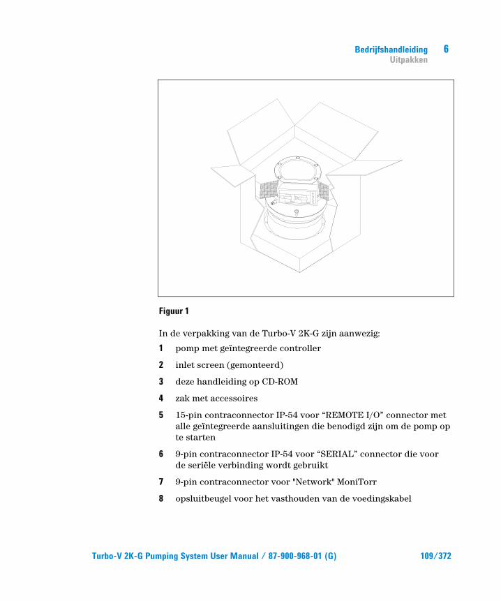
Bedrijfshandleiding Uitpakken
6
Turbo-V 2K-G Pumping System User Manual / 87-900-968-01 (G) 109/372
Figuur 1
In de verpakking van de Turbo-V 2K-G zijn aanwezig:
1 pomp met geïntegreerde controller
2 inlet screen (gemonteerd)
3 deze handleiding op CD-ROM
4 zak met accessoires
5 15-pin contraconnector IP-54 voor “REMOTE I/O” connector met alle geïntegreerde aansluitingen die benodigd zijn om de pomp op te starten
6 9-pin contraconnector IP-54 voor “SERIAL” connector die voor de seriële verbinding wordt gebruikt
7 9-pin contraconnector voor "Network" MoniTorr
8 opsluitbeugel voor het vasthouden van de voedingskabel

6 Bedrijfshandleiding Installatie
110/372 Turbo-V 2K-G Pumping System User Manual / 87-900-968-01 (G)
Installatie
WAARSCHUWING!
De pomp moet in verband met zijn gewicht met speciale hef- en transportwerktuigen worden gehanteerd. Gebruik hiervoor de speciale oogbouten die zijn vastgeschroefd in de gaten in het pomplichaam.
VOORZICHTIG! Verwijder niet de opgeboute afdekking voordat de turbopomp met het systeem wordt verbonden.
VOORZICHTIG! Verwijder de bescherming van de connectors uitsluitend nadat de turbopomp aan het systeem is bevestigd.
Figuur 2
De pomp mag niet geïnstalleerd en/of gebruikt worden in ruimten die blootgesteld zijn aan de weersomstandigheden (regen, vorst, sneeuw), stof, agressieve gassen, of in ruimten met ex¬plosiegevaar of zeer groot brandgevaar.
WA
RN
ING
REMOVE THIS PROTECTION AFTER
MECHANICAL INSTALLATION
NO
CHAMBER
YES

Bedrijfshandleiding Installatie
6
Turbo-V 2K-G Pumping System User Manual / 87-900-968-01 (G) 111/372
Tijdens de werking moeten de volgende omgevingscondities aanwezig zijn
� max. druk: 2 bar boven de atmosferische druk
� temperatuur: van +5 °C tot +40 °C (zie grafiek in de bijlage “Technical Information”)
� relatieve vochtigheid: 0 – 95 % (niet condenserend).
In aanwezigheid van magnetische velden moet de pomp op passende wijze afgeschermd worden. Zie de bijlage “Technical Information” voor meer informatie
De Turbo-V 2K-G moet op een primaire pomp aangesloten zijn (zie schema in "Technical information").
De Turbo-V 2K-G kan in alle standen worden geïnstalleerd. Bevestig de Turbo-V 2K-G in een stabiele positie en verbind de inlaatflens van de turbopomp met een vaste contraflens die een koppel van 10600 Nm rondom de eigen as kan verdragen.
De turbopomp met ISO ingangsflens moet bevestigd worden aan de vacuümkamer met behulp van bouten. De volgende tabel beschrijft het aantal benodigde bouten en met welk koppel Agilent adviseert om ze aan te halen.
Tab. 1
FLENS KLEMTYPE NR. AANHAAL KOPPEL
ISO 250 F Bout met M10 schroefdraad 12 22 Nm
OPMERKING De Turbo-V 2K-G kan niet bevestigd worden via zijn basis. Het systeem mag uitsluitend bevestigd worden via zijn ISO 250F flens. De bevestiging moet conform de norm ISO 1609 gebeuren. Er moeten stalen bouten worden gebruikt met een weerstandsklasse van minstens 500 N/mm2.

6 Bedrijfshandleiding Installatie
112/372 Turbo-V 2K-G Pumping System User Manual / 87-900-968-01 (G)
VOORZICHTIG! De Turbo-V 2K-G behoort tot de tweede installatiecategorie (of overspanningscategorie) die door de norm EN 61010-1 is voorzien. Sluit deze inrichting dus aan op een voedingslijn die aan deze categorie voldoet. Gebruik de bijgeleverde contraconnectoren om de beveiligingsgraad IP-54 te garanderen. De Turbo-V 2K-G bezit connectoren voor de ingangen/uitgangen en voor de seriële communicatie die aangesloten moeten worden op de externe circuits, zodat geen enkel deel onder spanning toegankelijk is. Controleer of de inrichting verbonden met de Turbo-V 2K-G goed geïsoleerd is, ook in geval van een enkele storing zoals voorzien door de norm EN 61010-1.
Zie “Technical Information” voor installatie van accessoires die als optie verkrijgbaar zijn.

Bedrijfshandleiding Gebruik
6
Turbo-V 2K-G Pumping System User Manual / 87-900-968-01 (G) 113/372
Gebruik In deze paragraaf worden de belangrijkste gebruiksprocedures vermeld. Breng alle elektrische en pneumatische aansluitingen tot stand alvorens het systeem te gebruiken. Tijdens de eventuele verwarming van de vacuümkamer mag de temperatuur op de inlaatflens niet meer dan 80 °C bedragen.
Tijdens de werking van de pomp, mag de temperatuur van de rotor nooit 120 °C overschrijden.
De gebruiker moet controleren of de correcte bedrijfswijze is ingesteld, afhankelijk van het te pompen gas: 1 voor stikstof en lichtere gassen, 0 voor Argon (default). Voor meer details wordt verwezen naar de bijlage "Technical Information".
WAARSCHUWING!
Laat de pomp nooit draaien als de inlaatflens niet op de vacuümkamer is aangesloten of als de afsluitflens niet gesloten is. Raak de turbopomp en eventuele accessoires niet tijdens het verwarmen aan. De hoge temperatuur kan lichamelijk letsel veroorzaken.
VOORZICHTIG! Vermijd schokken, trillingen of bruuske verplaatsingen van de turbopomp wanneer deze in werking is. De lagers kunnen anders beschadigd raken. Gebruik voor de luchttoevoer naar de pomp lucht of inert gas zonder stof of vaste deeltjes. De inlaatdruk via de hiervoor bestemde poort moet minder dan 1 bar (boven de atmosferische druk) bedragen. Deze pompen zijn voor het pompen van gassen met roetdeeltjes of vervuilende stoffen die de lagers aantasten, van een speciale poort voorzien, waardoor de pomp een stroom inert gas (stikstof of helium) ter bescherming van de lagers krijgt geleverd (zie bijlage “Technical Information”).
6 Bedrijfshandleiding Gebruik
114/372 Turbo-V 2K-G Pumping System User Manual / 87-900-968-01 (G)
VOORZICHTIG! Gebruik de pomp nooit bij corrosieve gassen of dampen die het materiaal aan de binnenkant van de pomp kunnen beschadigen.
WAARSCHUWING!
Wanneer de pomp wordt gebruikt voor het pompen van brandbare, giftige of radioactieve gassen, moeten de procedures worden gevolgd die speciaal voor elk type gas zijn opgesteld. Gebruik de pomp niet in aanwezigheid van explosieve gassen. De pomp is voor een hoge doorvoercapaciteit van stikstof, Argon en lichtere gassen ontworpen. Indien de noodzaak bestaat om zwaardere gassen dan Argon te pompen, wordt u verzocht om contact op te nemen met de Technische Service van Agilent voor informatie.
Gebruik van de Turbo-V 2K-G
Hoe wordt het systeem gestart Controleer, alvorens het systeem te starten, of de I/O contraconncetor verwijderd is. Als het systeem verbonden is met een remote I/O, controleer dan of het STOP signaal actief is (zie paragraaf "J1 – REMOTE I/O" in de bijlage "Technical Information").
Start het systeem via de volgende stappen:
1 verwijder de I/O contraconnector (indien aanwezig)
2 sluit het voedingsnet aan
3 breng de druk in de vacuümkamer op 0,1 mbar
4 geef aan de Turbo-V 2K-G het START signaal op een van de volgende manieren:
Bedrijfshandleiding Gebruik
6
Turbo-V 2K-G Pumping System User Manual / 87-900-968-01 (G) 115/372
a sluit de bijgeleverde I/O contraconnector aan
b geeft het START signaal op afstand via de I/O connector (zie paragraaf "J1 – REMOTE I/O" in de bijlage "Technical Information")
c geef het START signaal op afstand via de seriële interface RS 232/485 (zie paragraaf "RS 232/485 Communication Description" in de bijlage "Technical Information").
WAARSCHUWING!
Wanneer de voeding wordt geleverd en de bijgeleverde 15-pin connector is ingebracht, start de Turbo-V 2K-G automatisch.
VOORZICHTIG! De controller wordt reeds mechanisch en elektrisch aan de pomp verbonden geleverd. De controller kan slechts van het pomplichaam worden gescheiden door hiertoe bevoegd personeel van Agilent Vacuum Technologies.
OPMERKING Wanneer de Turbo-V 2K-G voor de eerste keer wordt gestart, start de controller automatisch het systeem met een speciale procedure die de lagers tegen mogelijke schade beschermt (SOFT START). Het systeem wordt via opeenvolgende stappen op volle snelheid gebracht, in een tijdsbestek dat van 10 minuten tot 1 uur kan variëren. Nadat het systeem de volle snelheid heeft bereikt, wordt de "soft start" procedure ontmachtigd en worden de volgende starten op de normale wijze uitgevoerd.
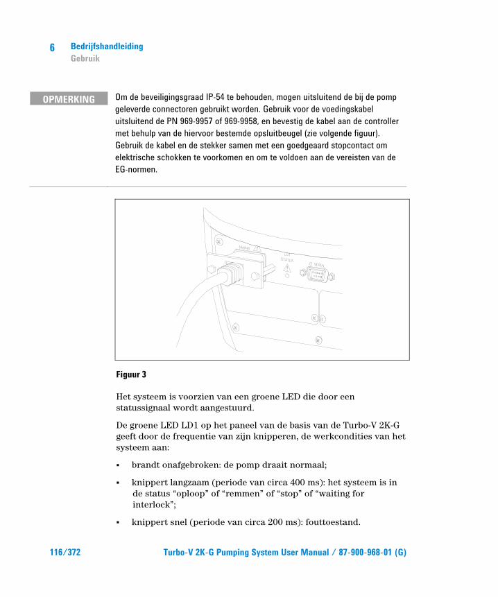
6 Bedrijfshandleiding Gebruik
116/372 Turbo-V 2K-G Pumping System User Manual / 87-900-968-01 (G)
OPMERKING Om de beveiligingsgraad IP-54 te behouden, mogen uitsluitend de bij de pomp geleverde connectoren gebruikt worden. Gebruik voor de voedingskabel uitsluitend de PN 969-9957 of 969-9958, en bevestig de kabel aan de controller met behulp van de hiervoor bestemde opsluitbeugel (zie volgende figuur). Gebruik de kabel en de stekker samen met een goedgeaard stopcontact om elektrische schokken te voorkomen en om te voldoen aan de vereisten van de EG-normen.
Figuur 3
Het systeem is voorzien van een groene LED die door een statussignaal wordt aangestuurd.
De groene LED LD1 op het paneel van de basis van de Turbo-V 2K-G geeft door de frequentie van zijn knipperen, de werkcondities van het systeem aan:
� brandt onafgebroken: de pomp draait normaal;
� knippert langzaam (periode van circa 400 ms): het systeem is in de status “oploop” of “remmen” of “stop” of “waiting for interlock”;
� knippert snel (periode van circa 200 ms): fouttoestand.

Bedrijfshandleiding Gebruik
6
Turbo-V 2K-G Pumping System User Manual / 87-900-968-01 (G) 117/372
Hoe wordt de Turbo-V 2K-G gestopt Om de pomp te stoppen, kan één van de volgende methoden worden gebruikt:
1 verwijdering van de bijgeleverde I/O contraconnector
2 verzending van een STOP signaal op afstand via de I/O connector (zie paragraaf "J1 – REMOTE I/O" in de bijlage "Technical Information")
3 verzending van een STOP signaal op afstand via de seriële interface RS 232/485 (zie paragraaf "RS 232/485 Communication Description" in de bijlage "Technical Information").
Noodstop Om de Turbo-V 2K-G in noodomstandigheden te stoppen, moet de stroomtoevoerkabel van de controller losgemaakt worden. Men moet er echter rekening mee houden dat hiermee niet alleen de pompvoeding volledig wordt uitgeschakeld, maar ook alle andere functies van de controller worden onderbroken, zoals bijvoorbeeld het beheer van de Purge en de gestuurde Vent en de mogelijkheid om te communiceren met het systeem waarin de pomp is ingebouwd, via I/O’s, seriële of Profibus verbinding.
Bovendien kan met deze handeling niet gegarandeerd worden dat de rotor onmiddellijk stopt, omdat de draaisnelheid ervan afneemt op basis van het vacuümniveau in het systeem.
6 Bedrijfshandleiding Onderhoud
118/372 Turbo-V 2K-G Pumping System User Manual / 87-900-968-01 (G)
Onderhoud De Turbo-V 2K-G is onderhoudsvrij. Eventuele werkzaamheden moeten door bevoegd perso¬neel worden uitgevoerd.
WAARSCHUWING!
Alvorens werkzaamheden aan het systeem uit te voeren, de stekker verwijderen, de pomp met behulp van de hiervoor bestemde klep ontluchten en wachten totdat de rotor volledig stil staat en de oppervlaktetemperatuur van de pomp onder een temperatuur van 50 °C is gezakt.
In geval van storing is het mogelijk om de reparatiedienst van Agilent of de "Agilent advanced exchange service" in te schakelen: zo krijgt men een ruilpomp ter vervanging van de defecte pomp.
OPMERKING Alvorens de pomp ter reparatie of ruil naar de fabrikant op te sturen, moet de bij deze handleiding gevoegde kaart "Veiligheid en Gezond¬heid" volledig ingevuld naar het plaatselijke verkoopkantoor worden gestuurd. Een kopie van deze kaart moet vóór versturing bij de pomp in de verpakking worden gevoegd.
Mocht het systeem gesloopt worden, ga dan overeenkomstig de specifieke nationale wetgeving te werk.
Bedrijfshandleiding Afvalverwerking
6
Turbo-V 2K-G Pumping System User Manual / 87-900-968-01 (G) 119/372
Afvalverwerking Betekenis van het logo "WEEE" op de etiketten. Het onderstaande symbool wordt aangebracht in overeenstemming met de EG-richtlijn "WEEE". Dit symbool (alleen geldig voor de landen van de Europese Gemeenschap) geeft aan dat het product waarop het is aangebracht, NIET mag worden afgevoerd samen met mormaal huisvuil of industrieel afval, maar gescheiden moet worden ingezameld. De eindgebruiker wordt dus verzocht contact op te nemen met de leverancier van het apparaat, zij het de fabrikant of een wederverkoper, om het proces van gescheiden inzameling en verwerking in gang te zetten, na de van toepassing zijnde termen en voorwaarden van het verkoopcontract te hebben gecontroleerd.

6 Bedrijfshandleiding Afvalverwerking
120/372 Turbo-V 2K-G Pumping System User Manual / 87-900-968-01 (G)
Turbo-V 2K-G Pumping System User Manual
121/372
7 Istruktionsbog Sikkerhedsanvisninger for Molekylære turbopumper 122 Generel Information 123 Opbevaring 125 Forberedelse før installation 126 Installation 128 Anvendelse 131 Brug af Turbo-V 2K-G 132 Start af systemet 132 Afbrydelse af Turbo-V 2K-G 134 Nødstop 135 Vedligeholdelse 136 Bortskaffelse 137 Oversættelse af originalinstruktionerne
7 Istruktionsbog Sikkerhedsanvisninger for Molekylære turbopumper
122/372 Turbo-V 2K-G Pumping System User Manual / 87-900-968-01 (G)
Sikkerhedsanvisninger for Molekylære turbopumper De molekylære turbopumper, der er beskrevet i nærværende brugsanvisning, har en stor kinetisk energi, der skyldes den høje omdrejningshastighed kombineret med deres rotorers specifikke vægt.
Hvis der er en fejl i systemet, for eksempel på grund af en kontakt mellem rotor og stator, eller fordi rotoren går i stykker, kan omdrejningsenergien spredes.
ADVARSEL!
For at undgå materielle skader samt at operatørerne kommer til skade, er det strengt nødvendigt nøje at overholde installeringsvejledningen i denne brugsanvisning!
Istruktionsbog Generel Information
7
Turbo-V 2K-G Pumping System User Manual / 87-900-968-01 (G) 123/372
Generel Information Dette udstyr er beregnet til professionel anvendelse. Brugeren bør læse denne brugsanvisning og anden yderligere information fra Agilent, før udstyret anvendes. Agilent tager ikke ansvar for skader helt eller delvis som følge af tilsidesættelse af disse instruktioner, fejlagtig brug af personer uden tilstrækkeligt kendskab, ukorrekt anvendelse af udstyret eller håndtering, der strider imod gældende lokale regler.
Turbo-V 2K-G-systemet omfatter en turbomolekylær pumpe til høje eller meget høje vakuumtilpasninger og aktuel styreenhed.
Systemet er egnet til pumpning af mange forskellige former for gas eller gasholdige blandinger, men kan ikke benyttes til pumpning af væsker eller faste partikler.
Pumpningen sker ved hjælp af en hurtigroterende turbine (33000 omdr./min.). Turbinen drives af en elektrisk trefasemotor med høj effekt. Turbo-V 2K-G er ikke fremstillet af skadelige stoffer og er derfor egnet til anvendelse, der kræver “rent” vakuum.
Endvidere er systemet udstyret med kontakter, som gør det muligt at fjernstyre systemet ved hjælp af en host computer, der er tilsluttet med seriel linie (RS232 eller RS485).
De følgende afsnit indeholder oplysningerne, der er nødvendige for at garantere sikkerhed for operatøren i forbindelse med anvendelse af udstyret. Bilaget “Technical Information” indeholder detaljerede oplysninger.

7 Istruktionsbog Generel Information
124/372 Turbo-V 2K-G Pumping System User Manual / 87-900-968-01 (G)
I brugsanvisningen anvendes følgende standard-rubrikker:
ADVARSEL!
Advarselsmeddelelserne informerer operatøren om, at en speciel procedure eller en vis type arbejde skal udføres præcist efter anvisningerne. I modsat fald er der risiko for svære personskader.
FORSIGTIG! Denne advarselsmeddelelse vises før procedurer, der skal følges nøje for ikke at risikere maskinskader.
BEMÆRK Dette gør opmærksom på vigtig information i teksten.
Istruktionsbog Opbevaring
7
Turbo-V 2K-G Pumping System User Manual / 87-900-968-01 (G) 125/372
Opbevaring Det er nødvendigt at overholde følgende forskrifter for at sikre optimal funktion og driftssikkerhed i de turbomolekylære pumper fra Agilent:
� Sørg for, at omgivelserne opfylder følgende betingelser i forbindelse med transport, flytning og opbevaring af pumperne:
� temperatur: fra –20 °C til +70 °C,
� relativ fugtighed: fra 0 til 95% (ikke kondenserende).
� Kunden skal altid starte de turbomolekylære pumper ved hjælp af Soft-Start funktionen ved modtagelse og start af pumperne for første gang.
� De turbomolekylære pumper må opbevares i 10 måneder fra forsendelsesdatoen.
FORSIGTIG! Hvis opbevaringsperioden af en eller anden grund er længere, er det nødvendigt at sende pumpen tilbage til fabrikken. Yderligere oplysninger fås ved henvendelse til den lokale Agilent repræsentant.

7 Istruktionsbog Forberedelse før installation
126/372 Turbo-V 2K-G Pumping System User Manual / 87-900-968-01 (G)
Forberedelse før installation Turbo-V 2K-G leveres i en speciel beskyttende emballage. Kontakt den lokale forhandler, hvis emballagen viser tegn på skader, der kan være opstået under transporten.
Sørg for, at Turbo-V 2K-G ikke tabes eller udsættes for stød ved udpakningen.
Fjern beskyttelsen fra konnektorerne, kun efter at turbopumpen er blevet fastgjort til systemet.
På grund af systemets vægt (35 kg) er det nødvendigt at benytte de tre øjebolte (placeret ved 120 °C), der er fastspændt på pumpehuset, for at fjerne pumpen fra emballagen.
Smid ikke emballagen ud. Materialet kan genbruges 100 % og opfylder EU-direktiv 85/399 om miljøbeskyttelse.
FORSIGTIG! Komponenter, der skal udsættes for vakuum, må ikke berøres med bare hænder, idet der er risiko for afgasning. Anvend altid handsker eller anden lignende beskyttelse.
BEMÆRK Turbo-V 2K-G beskadiges ikke, hvis den udsættes for omgivelsesluften. Det anbefales dog at holde pumpen lukket og forseglet, indtil den skal installeres i systemet. Herved undgås kontamination.
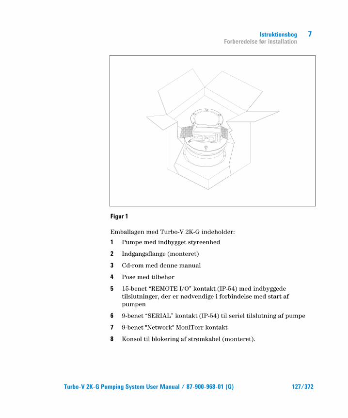
Istruktionsbog Forberedelse før installation
7
Turbo-V 2K-G Pumping System User Manual / 87-900-968-01 (G) 127/372
Figur 1
Emballagen med Turbo-V 2K-G indeholder:
1 Pumpe med indbygget styreenhed
2 Indgangsflange (monteret)
3 Cd-rom med denne manual
4 Pose med tilbehør
5 15-benet “REMOTE I/O” kontakt (IP-54) med indbyggede tilslutninger, der er nødvendige i forbindelse med start af pumpen
6 9-benet “SERIAL” kontakt (IP-54) til seriel tilslutning af pumpe
7 9-benet "Network" MoniTorr kontakt
8 Konsol til blokering af strømkabel (monteret).

7 Istruktionsbog Installation
128/372 Turbo-V 2K-G Pumping System User Manual / 87-900-968-01 (G)
Installation
ADVARSEL!
På grund af dens vægt skal pumpen håndteres ved hjælp af passende løfte- og transportudstyr. Benyt øjeboltene, der er fastspændt i gevindhullerne på pumpehuset.
FORSIGTIG! Fjern først den fastboltede afskærmning, når turbopumpen er blevet sluttet til systemet.
FORSIGTIG! Fjern beskyttelsen fra konnektorerne, kun efter at turbopumpen er blevet fastgjort til systemet.
Figur 2
Installér og anvend ikke pumpen i miljøer, der udsættes for påvirkninger fra atmosfæren (regn, sne, is), damp, aggressive gasser, og ligeledes ikke i eksplosivt eller brandfarligt miljø.
WA
RN
ING
REMOVE THIS PROTECTION AFTER
MECHANICAL INSTALLATION
NO
CHAMBER
YES
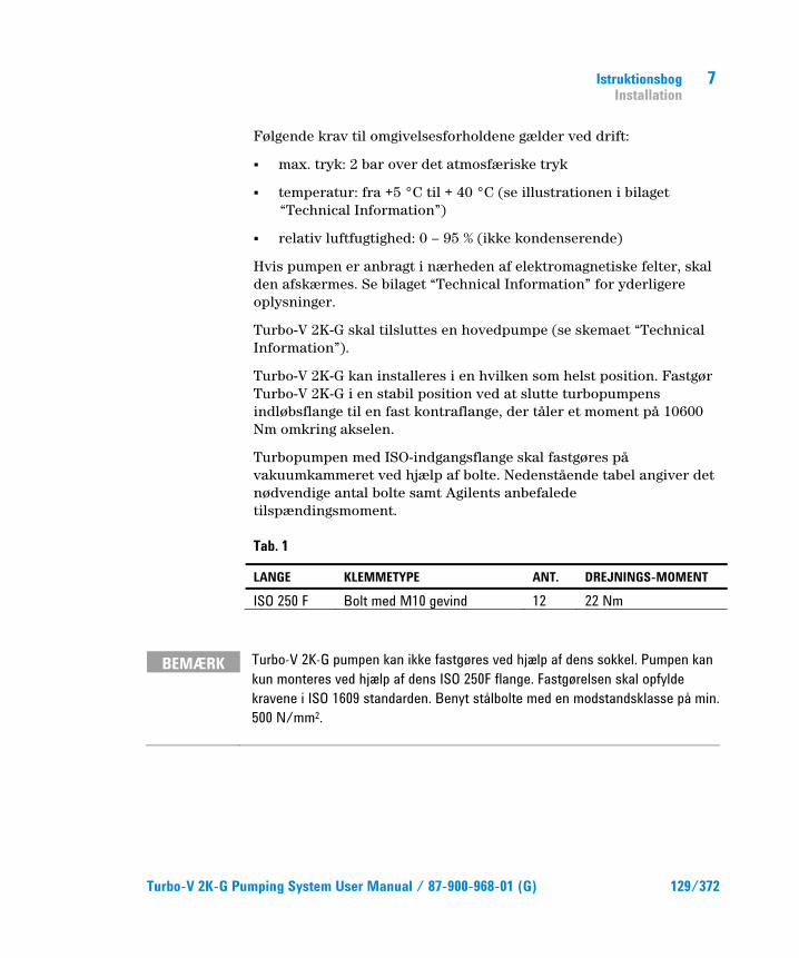
Istruktionsbog Installation
7
Turbo-V 2K-G Pumping System User Manual / 87-900-968-01 (G) 129/372
Følgende krav til omgivelsesforholdene gælder ved drift:
� max. tryk: 2 bar over det atmosfæriske tryk
� temperatur: fra +5 °C til + 40 °C (se illustrationen i bilaget “Technical Information”)
� relativ luftfugtighed: 0 – 95 % (ikke kondenserende)
Hvis pumpen er anbragt i nærheden af elektromagnetiske felter, skal den afskærmes. Se bilaget “Technical Information” for yderligere oplysninger.
Turbo-V 2K-G skal tilsluttes en hovedpumpe (se skemaet “Technical Information”).
Turbo-V 2K-G kan installeres i en hvilken som helst position. Fastgør Turbo-V 2K-G i en stabil position ved at slutte turbopumpens indløbsflange til en fast kontraflange, der tåler et moment på 10600 Nm omkring akselen.
Turbopumpen med ISO-indgangsflange skal fastgøres på vakuumkammeret ved hjælp af bolte. Nedenstående tabel angiver det nødvendige antal bolte samt Agilents anbefalede tilspændingsmoment.
Tab. 1
LANGE KLEMMETYPE ANT. DREJNINGS-MOMENT
ISO 250 F Bolt med M10 gevind 12 22 Nm
BEMÆRK Turbo-V 2K-G pumpen kan ikke fastgøres ved hjælp af dens sokkel. Pumpen kan kun monteres ved hjælp af dens ISO 250F flange. Fastgørelsen skal opfylde kravene i ISO 1609 standarden. Benyt stålbolte med en modstandsklasse på min. 500 N/mm2.
7 Istruktionsbog Installation
130/372 Turbo-V 2K-G Pumping System User Manual / 87-900-968-01 (G)
FORSIGTIG! Turbo-V 2K-G hører til den anden installationsklasse (eller overspændingsklasse) jf. normen EN 61010-1. Slut derfor anordningen til en forsyningslinie, som opfylder kravene i denne klasse. Benyt de medleverede kontakter for at sikre opretholdelse af IP-54 isoleringsbeskyttelsen. Turbo-V 2K-G er forsynet med konnektorer til ind-/udgange og til seriel kommunikation. Konnektorerne skal tilsluttes de eksterne kredsløb, således at det ikke er muligt at opnå adgang til de spændingsførende dele. Kontrollér, at anordningen, der er tilsluttet Turbo-V 2K-G, har en passende isolering. Dette gælder også i tilfælde af enkeltfejl som angivet i normen EN 61010-1.
Der henvises til bilaget “Technical Information” for oplysninger vedrørende installation af ekstraudstyret.
Istruktionsbog Anvendelse
7
Turbo-V 2K-G Pumping System User Manual / 87-900-968-01 (G) 131/372
Anvendelse Dette afsnit beskriver de vigtigste driftsprocedurer. Inden anvendelse af systemet, bør samtlige elektriske og pneumatiske tilslutninger udføres. I forbindelse med opvarmning af vakuumkammeret må indløbsflangens temperatur ikke overstige 80 °C. Rotorens temperatur må aldrig overskride 120 °C i forbindelse med brug af pumpen.
Operatøren skal kontrollere, at den korrekte funktion er indstillet i forhold til gastypen, som skal pumpes: 1 til kvælstof og lettere gasarter, 0 til argon (default indstilling). Vedrørende yderligere detaljer henvises til bilaget "Technical Information".
ADVARSEL!
Pumpen må aldrig aktiveres, hvis indløbsflangen ikke er tilsluttet vakuumkammeret, eller hvis pumpen ikke er lukket ved hjælp af lukkeflangen. Rør aldrig turbopumpen eller dens tilbehør i forbindelse med opvarmningsprocedurerne. Den høje temperatur kan resultere i skade på personer.
FORSIGTIG! Undgå sammenstød, vibrationer eller bratte bevægelser i forbindelse med brug af turbopumpen. Der er risiko for beskadigelse af lejerne. Pumpen skal forsynes med luft eller ædelgasser, der ikke indeholder støv eller faste partikler. Indgangstrykket ved den specielle dør skal være mindre end 1 bar (over atmosfærisk tryk). I forbindelse med pumpning af gasser, der indeholder partikler og andre aggressive foruredningsmidler, der skader lejerne, er disse pumper udstyret med en dør, igennem hvilken det er nødvendigt at forsyne pumpen med ædelgasser (kvælstof eller helium) for at beskytte lejerne (se bilaget “Technical Information”).
FORSIGTIG! Pumpen må aldrig bruges hvis der er gasser eller ætsende dampe, der kan beskadige pumpens indvendige dele.

7 Istruktionsbog Anvendelse
132/372 Turbo-V 2K-G Pumping System User Manual / 87-900-968-01 (G)
ADVARSEL!
Når pumpen anvendes til toksiske, brandfarlige eller radioaktive gasser, følges fremgangsmåden for den enkelte gastype. Anvend ikke pumpen til eksplosive gasser. Pumpen er projekteret til at sikre en høj pumpekapacitet for kvælstof, argon og lettere gasarter. Kontakt Agilents tekniske servicecenter vedrørende yderligere oplysninger, hvis det er nødvendigt at pumpe gasarter, som er tungere end argon.
Brug af Turbo-V 2K-G
Start af systemet Kontrollér, at I/O kontakten er blevet fjernet inden start af systemet. Kontrollér, at stopsignalet er aktiveret, hvis systemet er tilsluttet en fjernstyret I/O anordning (se afsnittet "J1 - REMOTE I/O" i bilaget "Technical Information").
Gør følgende for at starte systemet:
1 Fjern I/O kontakten (hvis den er monteret)
2 Tilslut strømmen
3 Indstil trykket i vakuumkammeret til 0,1 mbar
4 Overfør startsignalet til Turbo-V 2K-G på en af følgende måder:
a Tilslut den medleverede I/O kontakt
b Overfør det fjernstyrede startsignal ved hjælp af I/O kontakten (se afsnittet "J1 - REMOTE I/O" i bilaget "Technical Information")
c Overfør det fjernstyrede startsignal ved hjælp af den serielle grænseflade RS232/485 (se afsnittet "RS232/485 Communication Description" i bilaget "Technical Information").
Istruktionsbog Anvendelse
7
Turbo-V 2K-G Pumping System User Manual / 87-900-968-01 (G) 133/372
ADVARSEL!
Turbo-V 2K-G starter automatisk efter tilslutning af strøm og indsættelse af den medleverede 15-benede kontakt.
FORSIGITG! Ved levering er styreenheden allerede sluttet mekanisk og elektrisk til pumpen. Det er kun personale fra Agilent Vacuum Technologies, som må fjerne styreenheden fra pumpehuset.
BEMÆRK Når Turbo-V 2K-G startes for første gang, starter styreenheden automatisk systemet ved at benytte en særlig procedure, som beskytter lejerne mod potentielle skader (SOFT START). Systemet startes gradvist, indtil fuld hastighed nås (dette tidsrum varierer fra 10 minutter til 1 time). Når systemet har opnået fuld hastighed, frakobles "soft start" proceduren og de efterfølgende starter sker som normalt.
BEMÆRK Benyt udelukkende de kontakter, som leveres sammen med pumpen, for at opretholde IP-54 isoleringsbeskyttelsen. Benyt kun strømkablet art. nr. 969-9957 eller 969-9958 og fastgør strømkablet til styreenheden ved hjælp af den respektive konsol (se nedenstående figur Benyt dette kabel og stik sammen med en stikkontakt, som på passende måde er forbundet til jorden for at undgå elektriske stød og opfylde kravene ifølge CE(EF) normerne.

7 Istruktionsbog Anvendelse
134/372 Turbo-V 2K-G Pumping System User Manual / 87-900-968-01 (G)
Figur 3
Systemet er udstyret med en grøn LED, som overvåges af et signal for tilstand.
Den grønne LED LD1, der er anbragt på panelet på TURBO-V 2K-G’s fundament, angiver systemets funktion ved blink:
� konstant tændt: pumpen er i normal rotation
� langsomme blink: (periode på ca. 400 ms); systemet er i stilling for acceleration, bremsing, stop eller “Waiting for interlock”
� hurtige blink: (periode på ca. 200 ms); fejl.
Afbrydelse af Turbo-V 2K-G Benyt en af følgende metoder for at afbryde pumpen:
1 Fjern den medleverede I/O kontakt.
2 Overfør et fjernstyret stopsignal ved hjælp af I/O kontakten (se afsnittet "J1 - REMOTE I/O" i bilaget "Technical Information").
3 Overfør et fjernstyret stopsignal ved hjælp af den serielle grænseflade RS232/485 (se afsnit "RS232/485 Communication Description" i bilaget "Technical Information").
Istruktionsbog Anvendelse
7
Turbo-V 2K-G Pumping System User Manual / 87-900-968-01 (G) 135/372
Nødstop Afbrydelse af Turbo-V 2K-G i nødsituationer sker ved at koble ledningen fra styreenheden. Det er vigtigt at notere, at denne operation, ud over at afkoble fuldstændigt pumpens tilførsel, afkobler desuden også alle de andre controller funktioner, som for eksempel drift af Purge og af den Kontrollerede Ventilation og muligheden for at kommunikere med systemet hvortil pumpen er blevet tilsluttet ved brug af I/Os, Seriel eller Profibus forbindelse.
Desuden kan denne operation ikke sikre det omgående stop af rotoren: dens hastighed sænkes i henhold til vakuummet. Der findes inde i systemet.
7 Istruktionsbog Vedligeholdelse
136/372 Turbo-V 2K-G Pumping System User Manual / 87-900-968-01 (G)
Vedligeholdelse Turbo-V 2K-G behøver ikke nogen vedligeholdelse. Ethvert indgreb skal foretages af autoriseret personale.
ADVARSEL!
Inden der foretages noget som helst indgreb på systemet, skal strømmen først afbrydes, og luften i pumpen skal fjernes ved at åbne ventilen. Vent med foretagelse af indgrebet til rotoren er standset, og til temperaturen på pumpens overflade er under 50 °C.
I tilfælde af skader på systemet kontaktes et Agilent reparationsværksted eller “Agilent advanced exchange service”, der udskifter systemet med et repareret system.
BEMÆRK Inden systemet sendes til reparationsværkstedet eller “Agilent advanced axchange service” skal “Sikkerheds- og tilstandsdokumentet”, der er vedlagt denne instruktionsmanual, udfyldes. En kopi af dette dokument skal indsættes i systemets emballage inden afsendelse.
Skrotning af systemet skal foregå i overensstemmelse med det pågældende lands særlige love.

Istruktionsbog Bortskaffelse
7
Turbo-V 2K-G Pumping System User Manual / 87-900-968-01 (G) 137/372
Bortskaffelse Betydningen af "WEEE" logoet på mærkaterne. Nedenstående symbol anvendes i overensstemmelse med det såkaldte EU-direktiv "WEEE". Symbolet (kun gældende for EU-landene) viser, at produktet, som det sidder på IKKE må bortskaffes sammen med affald fra private husholdninger eller industriel affald men skal indleveres på en godkendt affaldsstation. Vi opfordrer derfor slutbrugeren til at kontakte leverandøren af anordningen, enten fabrikken eller en forhandler, for igangsættelse af afhentnings- og bortskaffelsesprocessen efter nøje at have kontrolleret betingelserne i salgskontrakten.
7 Istruktionsbog Bortskaffelse
138/372 Turbo-V 2K-G Pumping System User Manual / 87-900-968-01 (G)

Turbo-V 2K-G Pumping System User Manual
139/372
8 Bruksanvisning Säkerhetsanvisningar för Molekylära turbopumpar 140 Allmän Information 141 Förvaring 143 Förberedelser för installationen 144 Installation 146 Användning 149 Användning av Turbo-V 2K-G 150 Hur du startar systemet 150 Hur du stoppar Turbo-V 2K-G 153 Nödstopp 153 Underhåll 154 Bortskaffning 155 Översättning av originalinstruktionerna
8 Bruksanvisning Säkerhetsanvisningar för Molekylära turbopumpar
140/372 Turbo-V 2K-G Pumping System User Manual / 87-900-968-01 (G)
Säkerhetsanvisningar för Molekylära turbopumpar De molekylära turbopumparna som beskrivs i bruksanvisningen har en hög kinetisk energi beroende på den höga rotationshastigheten och rotorernas specifika massa.
I det fall fel skulle uppstå i systemet, t ex på grund av kontakt mellan rotor och stator eller om rotorn skulle skadas, kan det hända att rotationsenergin frigörs.
VARNING!
För att undvika skador på utrustningen och förhindra att skador orsakas på operatörer, måste installationsinstruktionerna som beskrivs i den här bruksanvisningen följas noga.

Bruksanvisning Allmän Information
8
Turbo-V 2K-G Pumping System User Manual / 87-900-968-01 (G) 141/372
Allmän Information Utrustningen är avsedd för yrkesmässig användning. Användaren bör läsa denna bruksanvisning, samt övrig dokumentation från Agilent före användning av utrustningen. Agilent tar inget ansvar för skador helt eller delvis till följd av åsidosättande av instruktionerna, olämplig användning av person utan tillräcklig kunskap, obehörigt bruk av utrustningen eller hantering som strider mot gällande lokala föreskrifter.
Systemet Turbo-V 2K-G bestär av en turbomolekylär pump för höga och mycket höga vakuumtillämpningar och en styrenhet.
Systemet kan pumpa många typer av gaser eller gasblandningar. Det kan dock inte användas för att pumpa vätskor eller fasta partiklar.
Pumpningen åstadkoms med hjälp av en högvarvig turbin (max 33000 varv/minut) som drivs av en trefas högeffektsmotor. Inga tillsatsämnen används i Turbo-V 2K-G, som därför passar för tillämpningar som kräver ett "rent" vakuum.
Systemet är utrustat med hjälpkontakter och via dessa kan systemet fjärrstyras med hjälp av en centraldator med seriell anslutning (RS232 eller RS485).
De följande avsnitten innehåller all information som behövs för att garantera operatörens säkerhet under användningen. Detaljerade uppgifter finns i bilagan "Technical information".

8 Bruksanvisning Allmän Information
142/372 Turbo-V 2K-G Pumping System User Manual / 87-900-968-01 (G)
I bruksanvisningen används följande standard-rubriker:
VARNING!
Varningsmeddelandena informerar operatören om att en speciell procedur eller en viss typ av arbete måste utföras exakt enligt anvisningarna. I annat fall finns risk för svåra personskador.
OBSERVER! Detta varningsmeddelande visas framför procedurer som måste följas exakt för att inte risk för maskinskada skall uppstå.
OBSERVERA Detta visar på viktig information i texten.

Bruksanvisning Förvaring
8
Turbo-V 2K-G Pumping System User Manual / 87-900-968-01 (G) 143/372
Förvaring Respektera följande anvisningar för att garantera optimal prestanda och driftsäkerhet för Agilent turbomolekylära pumpar:
� Vid transport, flytt och lagring av pumparna ska följande omgivningsförhållanden respekteras:
� Temperaturområde: -20 °C till +70 °C.
� Relativ fuktighet: 0 till 95 % (utan kondens).
� Kunden ska alltid mjukstarta de turbomolekylära pumparna när de mottas och sätts i drift för första gången.
� De turbomolekylära pumparna kan lagras i 10 månader från leveransdatumet.
OBSERVER! Om lagringstiden av någon anledning är längre måste pumpen skickas tillbaka till fabriken. Var god och kontakta den lokala Agilent-återförsäljaren för ytterligare information.

8 Bruksanvisning Förberedelser för installationen
144/372 Turbo-V 2K-G Pumping System User Manual / 87-900-968-01 (G)
Förberedelser för installationen Turbo-V 2K-G levereras i ett särskilt skyddande emballage. Kontakta det lokala försäljningskontoret om emballaget visar tecken på skador som kan ha uppstått under transporten. Se till att Turbo-V 2K-G inte tappas eller utsätts för stötar vid uppackningen.
Ta bort kontakternas skydd endast efter att turbopumpen har satts fast på systemet.
På grund av dess vikt (35 kg) bör du använda de tre 120 °C lyftöglorna på pumphuset för att ta upp pumpen ur förpackningen.
Kasta inte packmaterialet i soporna. Materialet är återvinningsbart till 100 % och uppfyller EU-direktiv 85/399 om miljöskydd.
OBSERVER! Komponenter som skall utsättas för vakuum får inte hanteras med bara händer p g a kontamineringsrisken. Använd alltid handskar eller liknande skydd.
OBSERVERA Pumpen Turbo-V 2K-G skadas inte av normal luftpåverkan. Det rekommenderas dock att hålla pumpen stängd och förseglad tills den installeras i systemet. Detta för att förebygga förorening av systemet.

Bruksanvisning Förberedelser för installationen
8
Turbo-V 2K-G Pumping System User Manual / 87-900-968-01 (G) 145/372
Figur 1
Turbo-V 2K-G förpackning innehåller:
1 Pump med inbyggd styrenhet
2 Intagsfläns (monterad)
3 Denna bruksanvisning på CD-ROM
4 Påse med tillbehör
5 15-polig kontakt IP54 "REMOTE I/O" med inbyggda anslutningar som behövs för att kunna starta pumpen
6 9- polig kontakt IP54 "SERIAL" som används för den seriella anslutningen
7 9-polig kontakt "Network" MoniTorr
8 Kabelklammer för att hålla fast strömkabeln

8 Bruksanvisning Installation
146/372 Turbo-V 2K-G Pumping System User Manual / 87-900-968-01 (G)
Installation
VARNING!
På grund av vikten måste pumpen flyttas med hjälp av lämpliga lyft- och flytthjälpmedel. Använd lyftöglorna som är fastskruvade i de gängade hålen på pumphuset.
OBSERVER! Ta inte bort skruvlocket förrän turbopumpen ansluts till systemet.
OBSERVER! Ta bort kontakternas skydd endast efter att turbopumpen har satts fast på systemet.
Figur 2
Installera och använd inte pumpen i miljöer som utsätts för påverkan från atmosfären (regn, snö, is), damm, aggressiva gaser, och inte heller i explosiv eller brandfarlig miljö.
Följande krav på omgivningsförhållanden gäller vid drift:
WA
RN
ING
REMOVE THIS PROTECTION AFTER
MECHANICAL INSTALLATION
NO
CHAMBER
YES
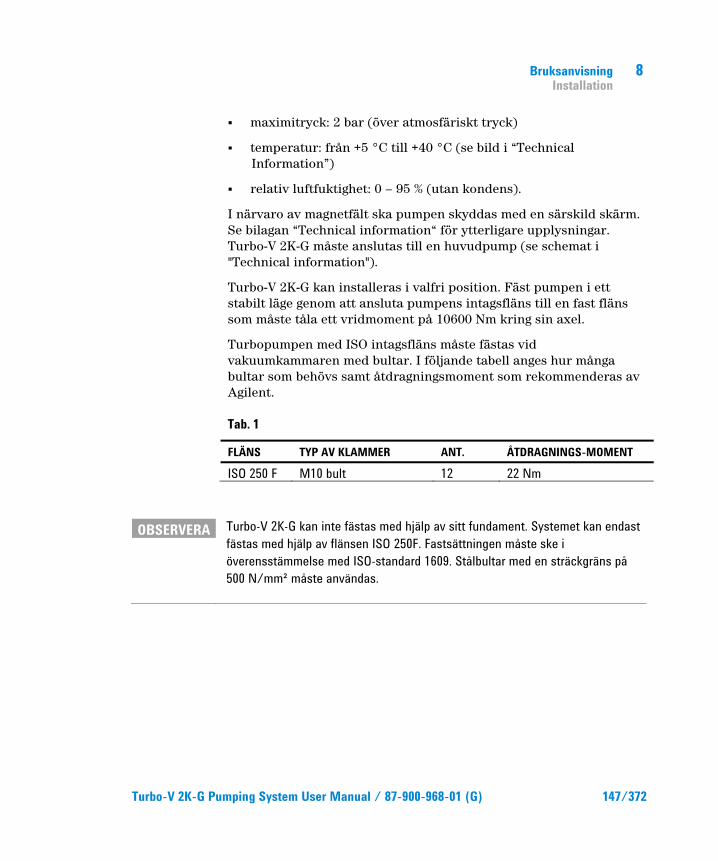
Bruksanvisning Installation
8
Turbo-V 2K-G Pumping System User Manual / 87-900-968-01 (G) 147/372
� maximitryck: 2 bar (över atmosfäriskt tryck)
� temperatur: från +5 °C till +40 °C (se bild i “Technical Information”)
� relativ luftfuktighet: 0 – 95 % (utan kondens).
I närvaro av magnetfält ska pumpen skyddas med en särskild skärm. Se bilagan “Technical information“ för ytterligare upplysningar. Turbo-V 2K-G måste anslutas till en huvudpump (se schemat i "Technical information").
Turbo-V 2K-G kan installeras i valfri position. Fäst pumpen i ett stabilt läge genom att ansluta pumpens intagsfläns till en fast fläns som måste tåla ett vridmoment på 10600 Nm kring sin axel.
Turbopumpen med ISO intagsfläns måste fästas vid vakuumkammaren med bultar. I följande tabell anges hur många bultar som behövs samt åtdragningsmoment som rekommenderas av Agilent.
Tab. 1
FLÄNS TYP AV KLAMMER ANT. ÅTDRAGNINGS-MOMENT
ISO 250 F M10 bult 12 22 Nm
OBSERVERA Turbo-V 2K-G kan inte fästas med hjälp av sitt fundament. Systemet kan endast fästas med hjälp av flänsen ISO 250F. Fastsättningen måste ske i överensstämmelse med ISO-standard 1609. Stålbultar med en sträckgräns på 500 N/mm² måste användas.
8 Bruksanvisning Installation
148/372 Turbo-V 2K-G Pumping System User Manual / 87-900-968-01 (G)
OBSERVER! Turbo-V 2K-G tillhör den andra installationsklassen (eller överspänningsklassen) enligt standard EN 61010-1. Anslut därför anordningen till en elledning som uppfyller kraven för denna klass. Använd de medlevererade kontakterna för att uppnå kapslingklass IP54. Turbo-V 2K-G är utrustad med kontaktdon för ingångarna/utgångarna och för den seriella kommunikationen som ska anslutas till de externa kretsarna så att det inte går att komma åt någon spänningsförande del. Kontrollera att anordningen som är ansluten till Turbo-V 2K-G har en lämplig isolering även vid ett enskilt fel enligt standard EN 61010-1.
Installation av tillbehörsutrustning beskrivs i "Technical Information”.
Bruksanvisning Användning
8
Turbo-V 2K-G Pumping System User Manual / 87-900-968-01 (G) 149/372
Användning Anvisningar för riktig användning finns i styrenhetens bruksanvisning.
Innan du använder systemet ska du utföra alla elektriska och pneumatiska anslutningar. Om vakuumkammaren uppvärms får temperaturen vid inloppet aldrig överstiga 80 °C.
När pumpen är i funktion får temperaturen på rotorn aldrig överstiga 120 °C. Användaren måste vara noga med välja rätt funktionssätt beroende på vilken gas som ska pumpas: 1 för kväve och lättare gaser, 0 för argon (standard). För ytterligare information, se bilagan "Technical Information".
VARNING!
Sätt aldrig igång pumpen om intagsflänsen varken är kopplad till vakuumkammaren eller är blockerad på plats med låsflänsen. Vidrör inte turbopumpen eller några tillbehör under uppvärmningen för att undvika brännskador.
OBSERVER! Undvik sammanstötningar, svängningar eller plötsliga förflyttningar av turbopumpen när den är igång. Lagren kan bli skadade. Pumpen ska förses med luft eller med ädelgaser som ärfria från damn eller andra partiklar. Ingångstrycket mot rätt dörr måsteunderstiga 1 bar (utöver det atmosfäriska trycket). För pumpning av gaser som innehåller partiklar eller föroreningar som är aggressiva för lagren, är dessa pumpar försedda med en speciell öppning igenom vilken man ska leda en ström av ädelgas (Kväve eller Helium) för att skydda lagren (se bilagan “Technical information”).
OBSERVER! Använd aldrig pumpen om det finns frätande gaser eller ångor som kan skada pumpens invändiga material.

8 Bruksanvisning Användning
150/372 Turbo-V 2K-G Pumping System User Manual / 87-900-968-01 (G)
VARNING!
Då pumpen används för pumpning av giftiga, lättantändliga eller radioaktiva gaser, bör man följa de särskilda anvisningarna för varje enskild gas. Använd ej pumpen i närheten av explosiva gaser. Pumpen är konstruerad för att pumpa stora mängder kväve, argon och lättare gaser. Om du skulle behöva pumpa gaser som är tyngre än argon, kontakta Agilents tekniska service för information.
Användning av Turbo-V 2K-G
Hur du startar systemet Kontrollera innan du startar systemet att I/O-kontakten har tagits bort. Om systemet är anslutet till en fjärrstyrd I/O-enhet måste du kontrollera att stoppsignalen är aktiv (se avsnitt “J1 - REMOTE I/O” i bilagan “Technical Information”).
Starta systemet på följande sätt:
1 Ta bort I/O-kontakten (om sådan finns)
2 Anslut pumpen till elnätet
3 Pumpa ned trycket i vakuumkammaren till 0,1 mbar
4 Skicka startsignal till Turbo-V 2K-G på något av följande sätt:
a Anslut den medlevererade I/O-kontakten
b Skicka en fjärrstyrd startsignal via I/O-kontakten (se avsnitt “J1 - REMOTE I/O” i bilagan “Technical Information”)
c Skicka en fjärrstyrd startsignal via det seriella gränssnittet RS232/485 (se avsnitt “RS232/485 Communication Description” i bilagan “Technical Information”).
Bruksanvisning Användning
8
Turbo-V 2K-G Pumping System User Manual / 87-900-968-01 (G) 151/372
VARNING!
När strömmen är påslagen och den 15-poliga kontakten (medföljer vid leveransen) är isatt startar Turbo-V 2K-G automatiskt.
OBSERVER! Styrenheten levereras mekaniskt och elektriskt ansluten till pumpen. Frånkoppling av styrenheten från pumpen får endast göras av auktoriserad personal från Agilent Vacuum Technologies.
OBSERVERA När du använder Turbo-V 2K-G för första gången startas systemet automatiskt av styrenheten med en speciell procedur som skyddar lagren mot eventuella skador (SOFT START). Systemet startas stegvis för att till slut uppnå max. hastighet. Detta tar mellan 10 min. och 1 timme. När systemet har uppnått max. hastighet deaktiveras proceduren för mjukstart. Följande starter sker därefter på normalt sätt.
OBSERVERA För att upprätthålla kapslingsklass IP54 ska du endast använda de kontakter som följer med pumpen. Använd endast strömkabeln art.nr. 969-9957 eller 969-9958. Fäst strömkabeln vid styrenheten med hjälp av en lämplig fästbygel (se följande figur). Använd sladden och kontakten tillsammans med en jordad anslutning för att undvika stötar och enligt krävande EU normer.
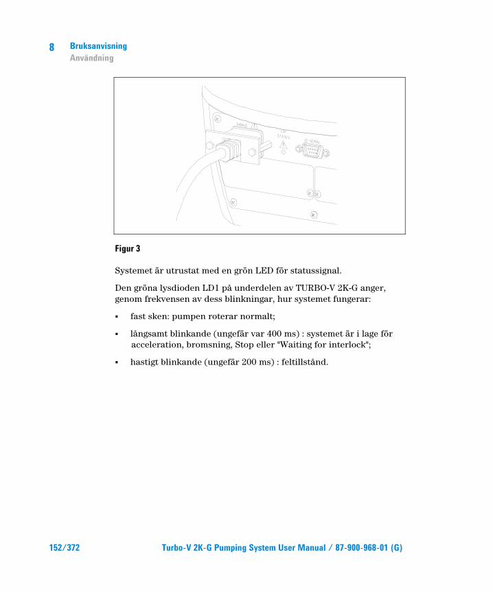
8 Bruksanvisning Användning
152/372 Turbo-V 2K-G Pumping System User Manual / 87-900-968-01 (G)
Figur 3
Systemet är utrustat med en grön LED för statussignal.
Den gröna lysdioden LD1 på underdelen av TURBO-V 2K-G anger, genom frekvensen av dess blinkningar, hur systemet fungerar:
� fast sken: pumpen roterar normalt;
� långsamt blinkande (ungefär var 400 ms) : systemet är i lage för acceleration, bromsning, Stop eller "Waiting for interlock";
� hastigt blinkande (ungefär 200 ms) : feltillstånd.

Bruksanvisning Användning
8
Turbo-V 2K-G Pumping System User Manual / 87-900-968-01 (G) 153/372
Hur du stoppar Turbo-V 2K-G Systemet kan stoppas på något av följande sätt:
1 Ta bort den medlevererade I/O-kontakten
2 Skicka en fjärrstyrd stoppsignal via I/O-kontakten (se avsnitt “J1 - REMOTE I/O” i bilagan “Technical Information”)
3 Skicka en fjärrstyrd stoppsignal via det seriella gränssnittet RS232/485 (se avsnitt “RS232/485 Communication Description” i bilagan “Technical Information”).
Nödstopp Dra ut elsladden från styrenheten för att utföra ett nödstopp av Turbo-V 2K-G. Utöver att denna operation totalt kopplar från pumpens försörjning, avaktiveras även alla andra funktioner på styrenheten, som till exempel hanteringen av rensningen och den styrda ventilatorn. Även kapaciteten att kommunicera med systemet i vilket pumpen integrerats via I/Os, Seriell eller Profibus avaktiveras.
Utöver detta, kan inte denna operation garantera ett omedelbart stopp av rotorn vars rotationshastighet minskar i funktion till vakuumet i systemet.
8 Bruksanvisning Underhåll
154/372 Turbo-V 2K-G Pumping System User Manual / 87-900-968-01 (G)
Underhåll Turbo-V 2K-G är underhållsfritt. Allt servicearbete måste utföras av auktoriserad personal.
VARNING!
Innan något arbete utförs på systemet måste pumpens strömförsörjning avbrytas och pumpen luftas genom att den aktuella ventilen öppnas. Vänta sedan tills rotorn stannat samt tills pumpens yttemperatur är lägre än 50 ºC.
Om pumpen havererar, kontakta Agilent reparationsverkstad eller Agilent utbytesservice, som kan ersätta systemet med ett renoverat system.
OBSERVERA Innan systemet lämnas in till tillverkaren för reparation eller utbyte mot en renoverad enhet, måste "hälso- och säkerhetsbladet" som medföljer bruksanvisningen fyllas i och skickas in till den lokala återförsäljaren. Bifoga dessutom en kopia av bladet med pumpen.
Skrotning av pumpen skall ske enligt gällande lagstiftning.

Bruksanvisning Bortskaffning
8
Turbo-V 2K-G Pumping System User Manual / 87-900-968-01 (G) 155/372
Bortskaffning Betydelse av logotypen "WEEE" på etiketterna. Symbolen som visas nedan har tillämpats i enlighet med CD-direktivet som har betecknats som "WEEE". Den här symbolen (gäller endast i de länder som tillhör den Europeiska Unionen) indikerar att produkten på vilken symbolen har applicerats INTE får skaffas bort tillsammans med vanliga hushålls- eller industriavfall, men att däremot ett differentierat uppsamlingssystem måste upprättas. Vi rekommenderar därför att slutanvändaren tar kontakt med leverantören av anordningen, oberoende om det handlar om moderföretaget eller återförsäljaren, för att kunna starta uppsamlings- och bortskaffningsprocessen, detta efter lämplig kontroll av kontraktsenliga tidsgränser och försäljningsvillkor.

8 Bruksanvisning Bortskaffning
156/372 Turbo-V 2K-G Pumping System User Manual / 87-900-968-01 (G)

Turbo-V 2K-G Pumping System User Manual
157/372
9 Instruksjon Manual Sikkerhetsanvisninger for Turbomolekylære pumper 158 Generell informasjon 159 Lagring 161 Klargjøre til installasjon 162 Installasjon 164 Bruk 167 Bruk av Turbo-V 2K-G 168 Hvordan starte opp systemet 168 Hvordan stoppe Turbo-V 2K-G 170 Nødstopp 171 Vedlikehold 171 Eliminering 172 Oversetting av den opprinnelige samsvarserklæringen

9 Instruksjon Manual Sikkerhetsanvisninger for Turbomolekylære pumper
158/372 Turbo-V 2K-G Pumping System User Manual / 87-900-968-01 (G)
Sikkerhetsanvisninger for Turbomolekylære pumper De turbomolekylære pumpene som er beskrevet i den følgende Bruksanvisningen har et høyt kinetisk energinivå som skyldes den høye roteringshastigheten i tillegg til den spesifikke massen til pumpenes rotor.
I tilfelle feil ved systemet, for eksempel på grunn av en kontakt mellom rotor og stator eller brudd på rotoren, kan roteringsenergien bli frigitt.
ADVARSEL!
For å unngå skader på utstyret og forebygge operatørskader må installasjonsanvisningene beskrevet i denne manualen følges nøye!

Instruksjon Manual Generell informasjon
9
Turbo-V 2K-G Pumping System User Manual / 87-900-968-01 (G) 159/372
Generell informasjon Dette utstyret er beregnet til bruk av profesjonelle brukere. Brukeren bør lese denne brukerveiledningen og all annen informasjon fra Agilent før utstyret tas i bruk. Agilent kan ikke holdes ansvarlig for hendelser som skjer på grunn av manglende oppfølging av disse instruksjonene, selv delvis, feilaktig bruk av utrent personell, ikke autoriserte endringer av utstyret eller handlinger som på noen måte er i strid med nasjonale bestemmelser.
Turbo-V 2K-G systemet består av en turbo-molekulær pumpe for bruk i høy- eller ultrahøye vakuumanlegg og en styreenhet.
Systemet kan pumpe mange typer gass eller gassblandinger, men er ikke egnet for pumping av væsker eller faste partikler.
Pumpingen oppnås med en høyhastighetsturbin (maks. 33000 opm) koplet til en trefaset elektrisk motor. Turbo-V 2K-G har ingen forurensende stoffer og er derfor egnet for anlegg med behov for "rene" vakuum.
Systemet har i tillegg hjelpekontakter slik at det kan fjernstyres med en vertsmaskin koplet gjennom en serielinje (RS232 eller RS485).
De følgende avsnitt inneholder all informasjon som er nødvendig for å sikre brukeren når utstyret er i bruk. For mer detaljert bruk vises det til tillegget "Technical Information".

9 Instruksjon Manual Generell informasjon
160/372 Turbo-V 2K-G Pumping System User Manual / 87-900-968-01 (G)
Denne veiledningen bruker følgende standard-protokoll:
ADVARSEL!
Disse meldingene skal tiltrekke seg brukerens oppmerksomhet til en spesiell fremgangsmåte eller praksis som, hvis den ikke følges, kan medføre alvorlige skader.
FORSIKTIG! Denne advarselen vises foran fremgangsmåter som, dersom de ikke følges, kan fore til at utstyret skades.
MERK Merknadene inneholder viktig informasjon som er hentet fra teksten.
Instruksjon Manual Lagring
9
Turbo-V 2K-G Pumping System User Manual / 87-900-968-01 (G) 161/372
Lagring For å garantere optimal drift og pålitelighet for Agilent turbomolekylære pumper må følgende anvisninger følges:
� Under transport, flytting og lagring av pumpene må ikke følgende miljøforhold overstiges:
� Temperatur: fra –20 °C til 70 °C.
� Relativ fuktighet: fra 0 til 95 % (uten kondensering).
� Kunden må alltid soft-starte de turbomolekylære pumpene når de mottas og startes opp første gang.
� Lagringstiden for en turbomolekylær pumpe er 10 måneder fra sendedato.
FORSIKTIG! Hvis lagringstiden av en hvilken som helst grunn er lenger må pumpen returneres til fabrikken. Vennligst kontakt den lokale Agilent-forhandleren for informasjon.

9 Instruksjon Manual Klargjøre til installasjon
162/372 Turbo-V 2K-G Pumping System User Manual / 87-900-968-01 (G)
Klargjøre til installasjon Turbo-V 2K-G leveres i en spesiell beskyttelsesemballasje. Viser denne tegn på skader som kan ha oppstått under transporten, må du ta kontakt med det lokale salgskontoret.
Når Turbo-V 2K-G pakkes ut, må du se til at det ikke slippes ned eller utsettes for noen form for støt.
Fjern beskyttelsen på koplingsstykket kun etter at turbopumpa er festet til systemet.
På grunn av vekten (35 kg), bruk de tre øyeboltene på 120 °C på pumpehuset for å trekke pumpen ut av esken.
Emballasjen må ikke kastes på en ulovlig måte. Alle materialer er 100 % resirkulerbare og er i samsvar med EU-direktiv 85/399 om miljøbeskyttelse.
FORSIKTIG! For å unngå avgassingsproblemer, må ingen del som skal utsettes for vakuum håndteres med bare hendene. Bruk alltid hansker eller andre og passende verneutstyr.
MERK Vanlig eksponering i miljøet kan ikke skade Turbo-V 2K-G. Vi anbefaler uansett å oppbevare pumpen lukket og forseglet helt til den skal installeres i systemet. Dette vil hindre at systemet forurenses.

Instruksjon Manual Klargjøre til installasjon
9
Turbo-V 2K-G Pumping System User Manual / 87-900-968-01 (G) 163/372
Figur 1
I esken med Turbo-V 2K-G finnes følgende:
1 Pump med inbyggd styrenhet
2 Intagsfläns (monterad)
3 Denna bruksanvisning på CD-ROM
4 Påse med tillbehör
5 15-polig kontakt IP54 "REMOTE I/O" med inbyggda anslutningar som behövs för att kunna starta pumpen
6 9- polig kontakt IP54 "SERIAL" som används för den seriella anslutningen
7 9-polig kontakt "Network" MoniTorr
8 Kabelklammer för att hålla fast strömkabeln
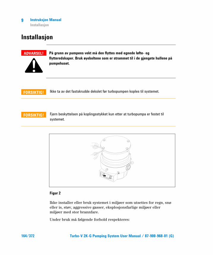
9 Instruksjon Manual Installasjon
164/372 Turbo-V 2K-G Pumping System User Manual / 87-900-968-01 (G)
Installasjon
ADVARSEL!
På grunn av pumpens vekt må den flyttes med egnede løfte- og flytteredskaper. Bruk øyeboltene som er strammet til i de gjengete hullene på pumpehuset.
FORSIKTIG! Ikke ta av det fastskrudde dekslet før turbopumpen koples til systemet.
FORSIKTIG! Fjern beskyttelsen på koplingsstykket kun etter at turbopumpa er festet til systemet.
Figur 2
Ikke installer eller bruk systemet i miljøer som utsettes for regn, snø eller is, støv, aggressive gasser, eksplosjonsfarlige miljøer eller miljøer med stor brannfare.
Under bruk må følgende forhold respekteres:
WA
RN
ING
REMOVE THIS PROTECTION AFTER
MECHANICAL INSTALLATION
NO
CHAMBER
YES

Instruksjon Manual Installasjon
9
Turbo-V 2K-G Pumping System User Manual / 87-900-968-01 (G) 165/372
� maksimalt trykk: 2 bar (over atmosfærisk trykk)
� temperatur: fra +5°C til +40°C (se diagram i tillegget “Technical Information”)
� relativ fuktighet: 0 - 95% (uten kondens)
Ved magnetfelt må pumpen beskyttes av dertil egnede skjermer. Se “Technical Information” for detaljer.
Turbo-V 2K-G må koples til en hovedpumpe (se skjema i "Technical Information").
Turbo-V 2K-G kan monteres i en valgfri stilling. Fest Turbo-V 2K-G i en stabil stilling med inngangsflensen festet mot en fast koplingsflens med et dreiemoment på 10600 Nm rundt aksen.
Turbopumpen med ISO inngangsflens må festes til vakuumkammeret med bolter. Tabellen nedenfor oppgir antall bolter som kreves, og strammemomentet anbefalt av Agilent.
Tab. 1
FLENS TYPE KLEMME ANT. STRAMME- MOMENT
ISO 250 F Bolt med M10 gjenge 12 22 Nm
MERK Turbo-V 2K-G kan ikke festes med bruk av bunnen. Systemet kan kun festes med ISO 250F flensen. Festingen må utføres i henhold til ISO 1609 standarden. Det må brukes stålbolter med en styrkeklasse på minst 500 N/mm2.
9 Instruksjon Manual Installasjon
166/372 Turbo-V 2K-G Pumping System User Manual / 87-900-968-01 (G)
FORSIKTIG! Turbo-V 2K-G hører til installasjonsklasse (eller overspenningsklasse) nummer 2 i følge EN 61010-1 standarden. Kople derfor anordningen til en hovedledning som tilfredsstiller kravene for denne klassen. Bruk kontaktene som følger med for å garantere IP54 beskyttelsen. Turbo-V 2K-G er utstyrt med koplingsstykker for inn-/utgangene og seriekommunikasjonen som må koples til de ytre strømkretsene slik at ingen deler under spenning er tilgjengelige. Forsikre deg om at isoleringen av anordningen koplet til Turbo-V 2K-G har en egnet isolering, også under forhold med en enkel feil i følge EN 61010-1 standarden.
For installasjon av tilleggsutstyr vises det til "Technical Information".
Instruksjon Manual Bruk
9
Turbo-V 2K-G Pumping System User Manual / 87-900-968-01 (G) 167/372
Bruk Alle instruksjoner for korrekt bruk finnes i dette avsnittet.
Les nøye gjennom denne manualen før systemet tas i bruk.
Mens oppvarmingen av kammeret pågår må temperaturen ved inngangsflensen ikke overskride 80 °C.
Mens pumpen er i funksjon må rotorens temperatur aldri overstige 120 °C.
Brukeren må passe på å innstille riktig driftsmodus i henhold til gassen som pumpes: 1 for nitrogen og lettere gasser, 0 for argon (standardmodus). For ytterligere detaljer, se vedlegget "Technical Information".
ADVARSEL!
Ikke start pumpen hvis inngangsflensen ikke er koplet til vakuumkammeret, eller ikke er lukket med lukkeflensen. Ikke berør turbopumpen eller noe av tilleggsutstyret under oppvarmingen. De høye temperaturene kan føre til brannskader.
FORSIKTIG! Unngå støt, svingninger eller plutselige bevegelser av turbinpumpen når den er i funksjon. Lagrene kan skades. Bruk støv- og partikkelfri luft eller inaktiv gass ved forsyning av pumpen. Trykket ved inngangen må ikke være mindre enn 1 bar (over atmosfærisk trykk). Ved pumping av gasser som inneholder partikler eller stoffer som er forurensende for lagrene, er disse pumpene utstyrt med en spesiell dør, som det er nødvendig å bruke for å mate pumpen med en strømning av uvirksom gass (nitrogen eller helium) for å beskytte lagrene (se vedlegget "Technical Information").
9 Instruksjon Manual Bruk
168/372 Turbo-V 2K-G Pumping System User Manual / 87-900-968-01 (G)
FORSIKTIG! Bruk aldri pumpen med etsende gasser eller damp som kan skade materiale inne i pumpen.
ADVARSEL!
Når pumpen brukes for å pumpe giftige, brannfarlige eller radioaktive gasser skal de relevante forskriftene for de enkelte gasstypene følges. Pumpen skal ikke brukes i eksplosjonsfarlige miljøer. Pumpen er utviklet for å pumpe store mengder med nitrogen, argon og lettere gasser. Hvis det er nødvendig å pumpe gasser som er tyngre enn argon, vennligst kontakt Agilent’s tekniske service for informasjon.
Bruk av Turbo-V 2K-G
Hvordan starte opp systemet Før systemet startes, kontroller at I/O kontakten er fjernet. Hvis systemet er koplet til en fjernstyrt I/O-anordning, forsikre deg om at stoppsignalet er aktivert (se avsnittet "J1 - REMOTE I/O" i vedlegget "Technical Information").
Gå frem på følgende måte for å starte systemet:
1 Fjern I/O kontakten (hvis finnes)
2 Kople til strømmen
3 Før trykket i vakuumkammeret til 0,1 mbar
4 Gi et startsignal til Turbo-V 2K-G på en av følgende måter:
a Kople til I/O kontakten som følger med
b Gi et fjernstyrt startsignal med I/O kontakten (se avsnittet "J1 - REMOTE I/O" i vedlegget "Technical Information")
c Gi et fjernstyrt startsignal med seriegrensesnittet RS232/485 (se avsnittet "RS232/485 Communication Description" i vedlegget "Technical Information").

Instruksjon Manual Bruk
9
Turbo-V 2K-G Pumping System User Manual / 87-900-968-01 (G) 169/372
ADVARSEL!
Turbo-V 2K-G starter automatisk når strømmen er tilkoplet og 15-veis kontakten som følger med er satt inn.
FORSIKTIG! Ved levering er styreenheten koplet mekanisk og elektrisk til pumpen. Demontering av styreenheten fra pumpehuset må kun utføres av autorisert personale fra Agilent Vacuum Technologies.
MERK Når Turbo-V 2K-G starter opp første gang, starter styreenheten automatisk systemet med en spesialprosedyre som beskytter lagrene mot mulige skader (SOFT START). Systemet kjøres trinnvis til full hastighet innen en tidsperiode som varierer fra 10 minutter til 1 time. Etter at systemet har nådd full hastighet deaktiveres "soft start" prosedyren, og de neste gangene systemet startes opp gjøres det på normal måte.
MERK For å opprettholde IP54 beskyttelsesnivået må kun kontaktene som følger med pumpen brukes. Bruk kun strömkabelen art.nr. 969-9957 eller 969-9958, og fest den til styreenheten med det bestemte festet (se figuren nedenfor). Bruk denne kabelen og støpselet sammen med en egnet jordet kontakt for å unngå elektrisk støt og for å overholde EU forskriftene.

9 Instruksjon Manual Bruk
170/372 Turbo-V 2K-G Pumping System User Manual / 87-900-968-01 (G)
Figur 3
Systemet leveres med en grønn LED styrt av et statussignal.
Den grønne lysdioden LD1 på TURBO-V 2K-G basepanel angir systemets funksjon ved hjelp av blink:
� den lyser fast: pumpen roterer normalt
� den blinker langsomt (ca. hver 400 ms): systemet er i stilling for akselerasjon, bremsing, stopp eller “Waiting for interlock”
� den blinker hurtig (ca. hver 200 ms): feiltilstand.
Hvordan stoppe Turbo-V 2K-G Stopp pumpen på en av følgende måter:
1 Kople fra I/O kontakten som følger med
2 Gi et fjernstyrt stoppsignal med I/O kontakt (se avsnittet "J1 - REMOTE I/O" i vedlegget "Technical Information")
3 Gi et fjernstyrt stoppsignal med seriegrensesnittet RS232/485 (se avsnittet "RS232/485 Communication Description" i vedlegget "Technical Information").
Instruksjon Manual Vedlikehold
9
Turbo-V 2K-G Pumping System User Manual / 87-900-968-01 (G) 171/372
Nødstopp Trekk ut nettkabelen fra styreenheten for å stoppe Turbo-V 2K-G i en nødsituasjon. Det må i alle tilfeller tas med i beregningen at dette inngrepet, foruten å koble ut pumpens mating fullstendig, kobler også ut alle andre funksjoner for kontrolleren, som for eksempel styring av Purge og kontrollert Vent samt evnen til å kommunisere med systemet der pumpen er integrert ved hjelp av I/Os, Serialport eller Profibus. Dessuten kan dette inngrepet ikke garantere at rotoren, hvis rotasjonshastighet vil senkes på grunnlag av graden vakuum som finnes i systemet, vil stanses øyeblikkelig.
Vedlikehold Turbo-V 2K-G er vedlikeholdsfritt. Alt arbeid på systemet må kun utføres av autorisert personell.
ADVARSEL!
Før noe arbeid gjøres på systemet må det frakoples tilførselen, pumpen må luftes ved å åpne den aktuelle ventilen og deretter vente til rotoren har stanset og pumpens overflatetemperatur er lavere enn 50 °C.
Dersom systemet stanser, må du ta kontakt med Agilents reparasjonservice eller med Agilents avanserte bytteservice som kan tilby overhalte system til erstatning for det ødelagte systemet.
MERK Før systemet returneres til produsenten for reparasjon, eller som innbytte for et overhalt system, må det vedlagte skjemaet "Helse og sikkerhet" fylles inn og sendes til det lokale salgskontoret. En kopi av dette arket må vedlegges systemet som sendes tilbake.
Dersom et system skal kasseres, må dette skje i henhold til nasjonale bestemmelser.
9 Instruksjon Manual Eliminering
172/372 Turbo-V 2K-G Pumping System User Manual / 87-900-968-01 (G)
Eliminering Betydelsen av symbolet på logo "WEEE" på etikettene. Symbolet nedenunder som finnes, er anvendt i henhold til EC-direktiv kalt "WEEE". Dette symbolet (som bare gjelder for land i Det europeiske fellesselskap), viser at produktet som det sitter på, IKKE må behandles som vanlig hus-industriavfall, men må legges i kildesortering. Derfor oppfordrer man den sluttelige brukeren av anordningen å henvende seg til leverandøren av anordningen, som kan være et firma eller en forhandler, som sørger for oppsamling og eliminering etter å ha kontrollert avtal og betingelser i kjøpekontrakten.
Turbo-V 2K-G Pumping System User Manual
173/372
10 Ohjekäsikirja Turbomolekyylipumppujen Turvaohjeet 174 Yleisiä tietoja 175 Varastointi 177 Valmistelut asennusta varten 178 Asennus 180 Käyttö 183 Turbo-V 2K-G -pumpun käyttö 184 Järjestelmän käynnistys 184 Turbo-V 2K-G -pumpun pysäytys 187 Hätäpysäytys 187 Huolto 188 Hävittäminen 189 Alkuperäisen ohjeiden käännös

10 Ohjekäsikirja Turbomolekyylipumppujen Turvaohjeet
174/372 Turbo-V 2K-G Pumping System User Manual / 87-900-968-01 (G)
Turbomolekyylipumppujen Turvaohjeet Tässä käyttöohjeessa kuvatuissa turbomolekyylipumpuissa on korkea määrä kineettistä energiaa, joka aiheutuu korkeasta pyörimisnopeudesta yhdistettynä pumppujen roottorien massaan.
Järjestelmän vikatilassa, esimerkiksi roottorin ja staattorin koskettaessa toisiaan tai roottorin rikkoutuessa, pyörimisenergia saattaa vapautua.
VAROITUS!
Tässä käyttöohjeessa kuvattuja asennusohjeita on noudatettava tarkasti laitteiston vaurioitumisen ja käyttäjien vahingoittumisen välttämiseksi!

Ohjekäsikirja Yleisiä tietoja
10
Turbo-V 2K-G Pumping System User Manual / 87-900-968-01 (G) 175/372
Yleisiä tietoja Tämä laite on tarkoitettu ammattimaiseen käyttöön. Ennen laitteen käyttöönottoa tulee käyttäjän lukea huolellisesti ohjekirja ja muut Agilentin toimittamat lisätiedot. Agilent ei ota vastuuta seurauksista, jotka johtuvat laitteen käyttöohjeiden täydellisestä tai osittaisesta laiminlyönnistä, ammattitaidottoman henkilön virheellisestä laitteen käytöstä, valtuuttamattomista toimenpiteistä tai kansallisen lainsäädännön vastaisesta käytöstä.
Turbo-V 2K-G on kokonaisjärjestelmä, joka muodostuu valvojalla varustetusta turbomolekyylipumpusta korkean ja ultrakorkean tyhjiön käyttöä varten.
Järjestelmä kykenee pumppaamaan monen tyyppisiä kaasuja tai kaasuyhdisteitä, mutta se ei sovellu nesteiden tai kiinteiden hiukkasten pumppaamiseen.
Pumppaus saadaan aikaan korkealla nopeudella (33000 kierrosta/min. max) pyörivän turbiinin avulla, jota käyttää korkeatehoinen kolmivaiheinen sähkömoottori. Turbo-V 2K-G -järjestelmässä ei ole lainkaan likaavia aineita, joten se soveltuu myös "puhdasta" tyhjiötä vaativiin käyttötarpeisiin.
Lisäksi pumpussa on apuliittimet, jotka mahdollistavat sen kauko-ohjauksen isäntätietokoneella, joka on kytketty siihen sarjakaapelilla (RS232 tai RS485).
Seuraavissa kappaleissa on kaikki tarpeelliset tiedot laitteen käyttäjän turvallisuuden takaamiseksi laitteen käytön aikana. Yksityiskohtaiset tiedot löytyvät osasta "Technical Information”.
10 Ohjekäsikirja Yleisiä tietoja
176/372 Turbo-V 2K-G Pumping System User Manual / 87-900-968-01 (G)
Tämä käsikirja käyttää seuraavanlaisia merkintöjä:
VAROITUS!
Vaara-merkit saavat käyttäjän kiinnittämään huomion erityiseen käyttö- tai toimintatapaan, jonka vääränlainen suoritus voi johtaa vakaviin henkilövaurioihin.
HUOMIO! Huomio-merkinnät varoittavat toiminnoista, joiden laiminlyönti voi johtaa laitteen vaurioitumiseen.
HUOM Huomautukset sisältävät tärkeää tekstissä käsiteltyä tietoa..
Ohjekäsikirja Varastointi
10
Turbo-V 2K-G Pumping System User Manual / 87-900-968-01 (G) 177/372
Varastointi Noudata seuraavia ohjeita, jotta Agilent turbomolekyylinen pumppu toimisi erittäin tehokkaasti ja luotettavasti:
� Kun pumppua kuljetetaan, siirretään ja varastoidaan, seuraavia ympäröiviä olosuhteita ei tule ylittää:
� lämpötila: -20 °C - 70 °C.
� suhteellinen kosteus: 0 – 95 % (ei tiivistävä).
� Asiakkaan tulee aina käynnistää turbomolekyylinen pumppu soft-start-tavalla vastaanottaessaan pumpun ja käyttäessään sitä ensimmäisen kerran.
� Turbomolekyylisen pumpun varastointiaika on 10 kuukautta toimituspäivästä.
HUOMIO! Jos varastointiaika on jostain syystä pidempi, pumppu tulee palauttaa tehtaalle. Pyydä lisätietoja paikalliselta Agilent-edustajalta.
10 Ohjekäsikirja Valmistelut asennusta varten
178/372 Turbo-V 2K-G Pumping System User Manual / 87-900-968-01 (G)
Valmistelut asennusta varten Turbo-V 2K-G toimitetaan erityisessä suojapakkauksessa; mikäli siinä on mahdollisesti kuljetuksen aikana tapahtuneita vaurioita, ottakaa yhteys paikalliseen myyntitoimistoon.
Pakkauksen purkamisen aikana tulee varoa erityisesti Turbo-V 2K-G putoamista tai siihen kohdistuvia iskuja tai tärinöitä. Pakkausta ei tule jättää ympäristöön.
Poista liittimien suoja ainoastaan sen jälkeen, kun turbopumppu on kiinnitetty järjestelmään.
Pumpun painosta (35 kg) johtuen se tulee nostaa pakkauksesta käyttämällä kolmea 120 ° silmukkapulttia, jotka on ruuvattu pumpun runkoon.
Pakkausmateriaali voidaan kierrättää kokonaisuudessaan ja se vastaa EY-direktiiviä 85/399 ympäristön suojelusta.
HUOMIO! Jotta kaasun vuoto-ongelmilta vältyttäisiin, ei tyhjiölle altistuviin osiin tule koskea paljain käsin. Käyttäkää aina käsineitä tai muuta sopivaa suojausta.
HUOM Turbo-V 2K-G ei vaurioidu ilmalle altistuessaan. On kuitenkin suositeltavaa säilyttää pumppu suljettuna ja sinetöitynä, kunnes se asennetaan järjestelmään. Siten estetään järjestelmän likaantuminen.

Ohjekäsikirja Valmistelut asennusta varten
10
Turbo-V 2K-G Pumping System User Manual / 87-900-968-01 (G) 179/372
Kuva 1
Turbo-V 2K-G -pumpun pakkauksessa on:
1 pompa con controller integrato
2 inlet screen (montato)
3 questo manuale su CD-ROM
4 sacchetto accessori
5 controconnettore a 15 vie “REMOTE I/O” IP-54 con integrate le connessioni necessarie a far partire la pompa
6 controconnettore a 9 vie “SERIAL” IP-54 da utilizzare per la connessione seriale
7 controconnettore a 9 pin per il "Network" MoniTorr
8 staffetta per la ritenzione del cavo di alimentazione (montata).
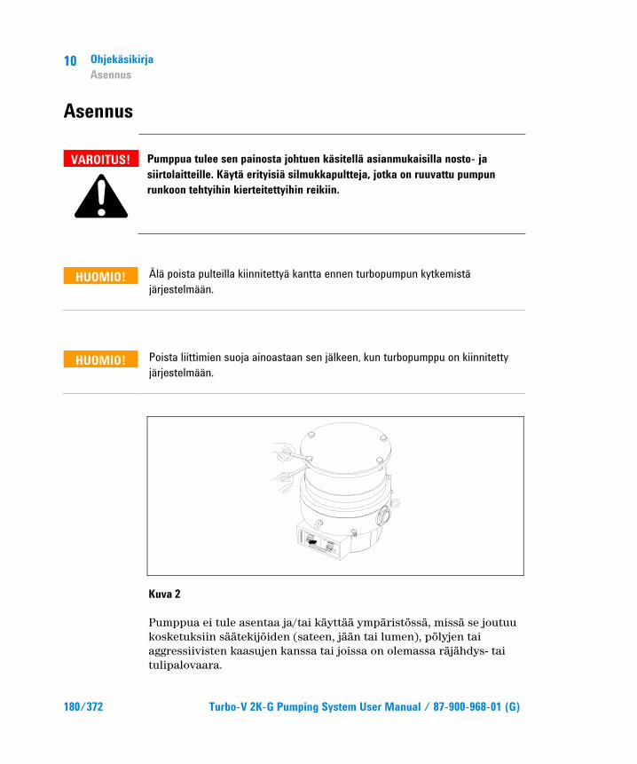
10 Ohjekäsikirja Asennus
180/372 Turbo-V 2K-G Pumping System User Manual / 87-900-968-01 (G)
Asennus
VAROITUS!
Pumppua tulee sen painosta johtuen käsitellä asianmukaisilla nosto- ja siirtolaitteille. Käytä erityisiä silmukkapultteja, jotka on ruuvattu pumpun runkoon tehtyihin kierteitettyihin reikiin.
HUOMIO! Älä poista pulteilla kiinnitettyä kantta ennen turbopumpun kytkemistä järjestelmään.
HUOMIO! Poista liittimien suoja ainoastaan sen jälkeen, kun turbopumppu on kiinnitetty järjestelmään.
Kuva 2
Pumppua ei tule asentaa ja/tai käyttää ympäristössä, missä se joutuu kosketuksiin säätekijöiden (sateen, jään tai lumen), pölyjen tai aggressiivisten kaasujen kanssa tai joissa on olemassa räjähdys- tai tulipalovaara.
WA
RN
ING
REMOVE THIS PROTECTION AFTER
MECHANICAL INSTALLATION
NO
CHAMBER
YES
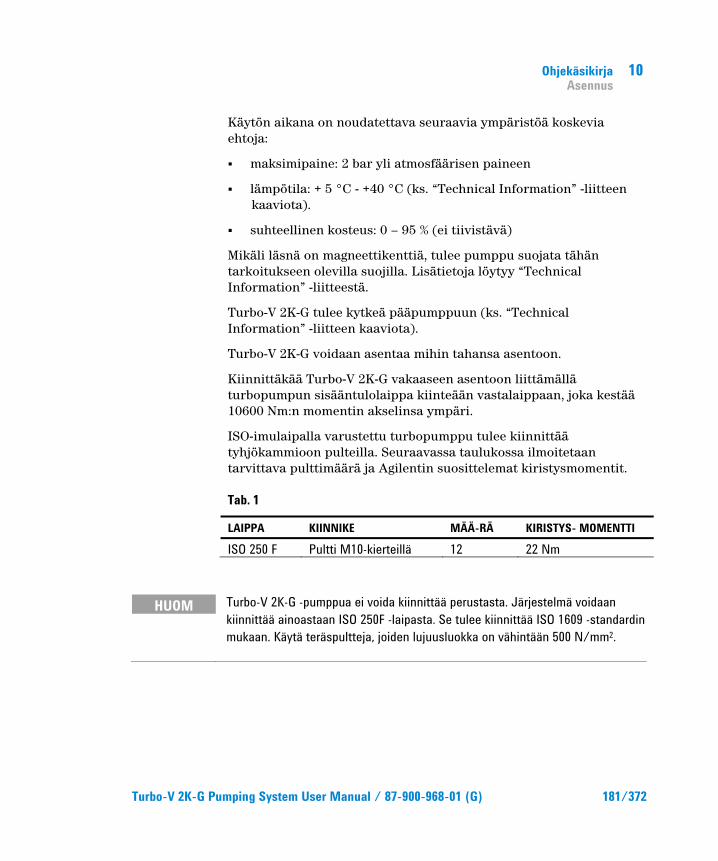
Ohjekäsikirja Asennus
10
Turbo-V 2K-G Pumping System User Manual / 87-900-968-01 (G) 181/372
Käytön aikana on noudatettava seuraavia ympäristöä koskevia ehtoja:
� maksimipaine: 2 bar yli atmosfäärisen paineen
� lämpötila: + 5 °C - +40 °C (ks. “Technical Information” -liitteen kaaviota).
� suhteellinen kosteus: 0 – 95 % (ei tiivistävä)
Mikäli läsnä on magneettikenttiä, tulee pumppu suojata tähän tarkoitukseen olevilla suojilla. Lisätietoja löytyy “Technical Information” -liitteestä.
Turbo-V 2K-G tulee kytkeä pääpumppuun (ks. “Technical Information” -liitteen kaaviota).
Turbo-V 2K-G voidaan asentaa mihin tahansa asentoon.
Kiinnittäkää Turbo-V 2K-G vakaaseen asentoon liittämällä turbopumpun sisääntulolaippa kiinteään vastalaippaan, joka kestää 10600 Nm:n momentin akselinsa ympäri.
ISO-imulaipalla varustettu turbopumppu tulee kiinnittää tyhjökammioon pulteilla. Seuraavassa taulukossa ilmoitetaan tarvittava pulttimäärä ja Agilentin suosittelemat kiristysmomentit.
Tab. 1
LAIPPA KIINNIKE MÄÄ-RÄ KIRISTYS- MOMENTTI
ISO 250 F Pultti M10-kierteillä 12 22 Nm
HUOM Turbo-V 2K-G -pumppua ei voida kiinnittää perustasta. Järjestelmä voidaan kiinnittää ainoastaan ISO 250F -laipasta. Se tulee kiinnittää ISO 1609 -standardin mukaan. Käytä teräspultteja, joiden lujuusluokka on vähintään 500 N/mm2.
10 Ohjekäsikirja Asennus
182/372 Turbo-V 2K-G Pumping System User Manual / 87-900-968-01 (G)
HUOMIO! Turbo-V 2K-G kuuluu toiseen EN 61010-1 säännösten mukaiseen asennusluokkaan (tai ylijänniteluokkaan). Kytke laite tämän vuoksi sähköverkkoon, joka täyttää tämän luokan vaatimukset. Käytä ohessa toimitettuja liittimiä taataksesi IP54-eristyksen. Turbo-V 2K-G laitteissa on liittimet sisääntuloille/ulostuloille sekä sarjakytkennälle, jotka on kytkettävä ulkoisiin järjestelmiin siten, ettei mihinkään jännitteen alaisena olevaan osaan päästä käsiksi. Varmista, että Turbo-V 2K-G laitteeseen kytketyn laitteen eristys riittää myös yksittäisen toimintahäiriön yhteydessä EN 61010-1 säännösten edellyttämällä tavalla.
Ks. “Technical Information” -liitettä lisävarusteiden asentamista varten.
Ohjekäsikirja Käyttö
10
Turbo-V 2K-G Pumping System User Manual / 87-900-968-01 (G) 183/372
Käyttö Tähän kappaleeseen on kirjattu tärkeimmät käyttötoimenpiteet. Suorittakaa ennen järjestelmän käyttöä kaikki sähkö- ja paineilmakytkennät. Tyhjiökammion mahdollisen lämmityksen aikana sisääntulolaipan lämpötila ei saa ylittää 80 °C:tta.
Pumpun toiminnan aikana roottorin lämpötila ei saa koskaan olla yli 120 °C.
Käyttäjän tulee varmistaa oikea toimintatapa pumpattavan kaasun mukaan: 1 typelle ja kevyille kaasuille, 0 argonille (oletustapa). Ks. lisätietoja "Technical Information"-liitteestä.
VAROITUS!
Älkää käyttäkö pumppua, ellei sisääntulolaippaa ole kytketty tyhjiökammioon tai pumppua suljettu sulkulaipalla. Älkää koskeko turbopumppuun tai sen lisäosiin lämmittämisen aikana. Korkea lämpötila saattaa aiheuttaa henkilöiden loukkaantumisia.
HUOMIO! Vältä kolhuja, heiluntaa tai äkkiliikkeitä turbopumpun toiminnan aikana, sillä laakerit voivat vahingoittua. Käytä pumpun ilmansyöttöön ilmaa tai jalokaasua, joissa ei ole pölyä tai hiukkasia. Erityisen aukon läpi syötettävän paineen tulee olla alle 1 baaria (yli atmosfäärisen paineen). Pumput on varustettu laakereille hiukkasia tai niitä saastuttavia aineita sisältävien aggressiivisten kaasujen pumppausta varten aukolla, jonka läpi pumppuun kuljetetaan jalokaasuja (Typpi tai Helium) laakereiden suojaamiseksi (katso “Technical Information” -liite).
HUOMIO! Älä käytä pumppua syövyttävien kaasujen tai höyryjen läheisyydessä: ne saattavat vahingoittaa pumpun sisämateriaaleja.
10 Ohjekäsikirja Käyttö
184/372 Turbo-V 2K-G Pumping System User Manual / 87-900-968-01 (G)
VAROITUS!
Kun pumppua käytetään myrkyllisten, paloherkkien tai radioaktiivisten kaasujen pumppaamiseen, noudattakaa jokaiselle kaasulle sopivaa menettelytapaa. Älkää käyttäkö pumppua räjähdysherkkien kaasujen lähellä. Pumppu on suunniteltu kuljettamaan suuria määriä typpeä, argonia ja kevyitä kaasuja. Jos joudut pumppaamaan argonia painavampia kaasuja, pyydä lisätietoja Agilentin teknisestä palvelusta.
Turbo-V 2K-G -pumpun käyttö
Järjestelmän käynnistys Tarkista ennen järjestelmän käynnistystä, että I/O-liitin on poistettu. Jos järjestelmä on kytketty I/O-etälaitteeseen, varmista että STOP-signaali on päällä (ks. "Technical Information"-liitteen kappale "J1 - REMOTE I/O").
Käynnistä järjestelmä seuraavasti:
1 rimuovere (se presente) il controconnettore I/O
2 collegare l'alimentazione di rete
3 portare la pressione all0'interno della camera a vuoto a 0,1 mbar
4 fornire alla Turbo-V 2K-G il segnale di START in uno dei seguenti modi:
a Liitä ohessa toimitettu I/O-liitin
b Anna START-etäsignaali I/O-liittimellä (ks. "Technical Information"-liitteen kappale "J1 - REMOTE I/O")
c Anna START-etäsignaali RS232/485 -sarjaliitännän kautta (ks. "Technical Information"-liitteen kappale "RS232/485 Communication Description").

Ohjekäsikirja Käyttö
10
Turbo-V 2K-G Pumping System User Manual / 87-900-968-01 (G) 185/372
VAROITUS!
Kytkettäessä sähkö päälle 15-nastaisen liittimen ollessa liitettynä Turbo-V 2K-G käynnistyy automaattisesti.
HUOMIO! Valvoja toimitetaan pumppuun mekaanisesti ja sähköisesti kytkettynä. Valvojan saa irrottaa pumpun rungosta ainoastaan Agilent Vacuum Technologies -yrityksen valtuuttama henkilö.
HUOM Kun Turbo-V 2K-G käynnistetään ensimmäisen kerran, valvoja käynnistää järjestelmän automaattisesti erikoistoimenpiteellä, joka suojaa laakereita vaurioilta (SOFT START). Järjestelmä käynnistetään peräkkäisillä askelilla täyteen nopeuteen asti 10 minuutista 1 tuntiin vaihtelevana aikana. Kun järjestelmä on saavuttanut täyden nopeuden, "soft start"-toimenpide kytketään pois ja seuraavat käynnistykset suoritetaan normaalisti.
HUOM Käytä ainoastaan pumpun ohessa toimitettuja liittimiä säilyttääksesi IP54-suojatason. Käytä sähkökaapelina ainoastaan tuotetta 969-9957 tai 969-9958 ja kiinnitä sähkökaapeli valvojaan erityisellä kannattimella (ks. seuraava kuva). Käytä tätä kaapelia ja pistoketta yhdessä oikein maadoitetun pistorasian kanssa, jotta sähköiskuilta vältytään ja CE- normien vaatimukset täyttyvät.
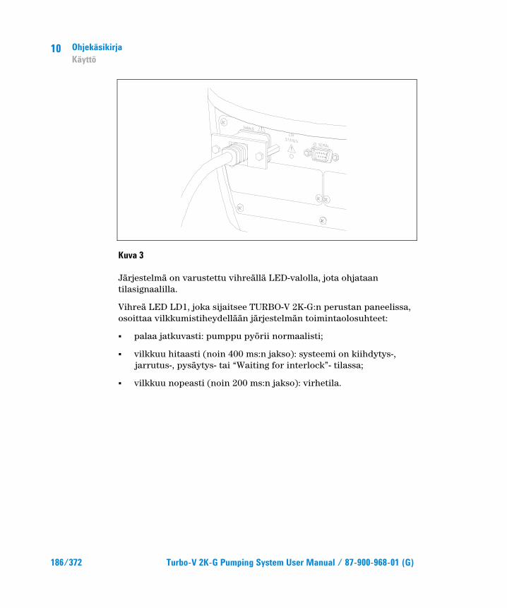
10 Ohjekäsikirja Käyttö
186/372 Turbo-V 2K-G Pumping System User Manual / 87-900-968-01 (G)
Kuva 3
Järjestelmä on varustettu vihreällä LED-valolla, jota ohjataan tilasignaalilla.
Vihreä LED LD1, joka sijaitsee TURBO-V 2K-G:n perustan paneelissa, osoittaa vilkkumistiheydellään järjestelmän toimintaolosuhteet:
� palaa jatkuvasti: pumppu pyörii normaalisti;
� vilkkuu hitaasti (noin 400 ms:n jakso): systeemi on kiihdytys-, jarrutus-, pysäytys- tai “Waiting for interlock”- tilassa;
� vilkkuu nopeasti (noin 200 ms:n jakso): virhetila.

Ohjekäsikirja Käyttö
10
Turbo-V 2K-G Pumping System User Manual / 87-900-968-01 (G) 187/372
Turbo-V 2K-G -pumpun pysäytys Pysäytä pumppu yhdellä seuraavista tavoista:
1 Poista ohessa toimitettu I/O-liitin.
2 Anna STOP-etäsignaali I/O-liittimellä (ks. "Technical Information"-liitteen kappale "J1 - REMOTE I/O").
3 Anna STOP-etäsignaali RS232/485 -sarjaliitännän kautta (ks. "Technical Information"-liitteen kappale "RS232/485 Communication Description").
Hätäpysäytys Turbo-V 2K-G on pysäytettävä hätätilassa irrottamalla sähkökaapeli ohjausyksiköstä. On kuitenkin otettava huomioon, että sen lisäksi, että tämä toiminto katkaisee täysin käytöstä poistetun pumpun virransyötön, se myös poistaa käytöstä kaikki muut ohjaimen toiminnot, kuten Purge- ja Vent-toimintojen hallinnan ja kommunikointimahdollisuuden sen järjestelmän kanssa, johon pumppu on kytketty I/O-, sarja- tai Profibus-portin välityksellä.
Lisäksi toimenpide ei takaa roottorin välitöntä pysähtymistä, koska pyörintänopeus laskee suhteessa järjestelmän alipaineen määrään.

10 Ohjekäsikirja Huolto
188/372 Turbo-V 2K-G Pumping System User Manual / 87-900-968-01 (G)
Huolto Turbo-V 2K-G ei vaadi lainkaan huoltoa. Mahdolliset toimenpiteet tulee jättää valtuutetun henkilön tehtäväksi.
VAROITUS!
Ennen minkään tyyppistä toimenpidettä järjestelmässä kytkekää se irti sähköverkosta, päästäkää pumppuun ilmaa avaamalla siihen tarkoitettu venttiili ja odottakaa roottorin täydellistä pysähtymistä. Antakaa tämän jälkeen pumpun pintalämmön laskea alle 50ºC:en.
Laitteen vahingoittuessa on mahdollista käyttää Agilentin korjauspalvelua tai "Agilent advanced exchange service" -vaihtopalvelua, jonka kautta saatte uudistetun pumpun vahingoittuneen tilalle.
HUOM Ennen järjestelmän lähettämistä valmistajalle korjausta tai vaihtopalvelua varten on ehdottomasti täytettävä ja toimitettava paikalliseen myyntitoimistoon "Turvallisuus ja Terveys” -kaavake, joka on liitteenä ohjekirjassa. Kyseisen kaavakkeen kopio tulee liittää järjestelmän pakkaukseen ennen sen lähettämistä.
Mikäli pumppu täytyy romuttaa, toimikaa sen hävittämisessä kansallisen lainsäädännön määräämällä tavalla.

Ohjekäsikirja Hävittäminen
10
Turbo-V 2K-G Pumping System User Manual / 87-900-968-01 (G) 189/372
Hävittäminen Pakkausmerkinnöissä olevan WEEE-logon merkitys. Alla näkyvä merkki on lisätty pakkaukseen EY:n ns. WEEE-direktiivin mukaisesti. Merkki (koskee ainoastaan Euroopan Unionin jäsenmaita) tarkoittaa, että tuotetta EI saa hävittää tavallisen kotitalous- tai teollisuusjätteen mukana, vaan se on toimitettava erilliseen keräyspisteeseen. Loppukäyttäjää kehotetaan sen vuoksi ottamaan keräys- ja hävittämisprosessia varten yhteyttä laitteen toimittajaan, olipa se sitten laitteen valmistaja tai jälleenmyyjä, tarkastettuaan ensin kaupan sopimusehdot.

10 Ohjekäsikirja Hävittäminen
190/372 Turbo-V 2K-G Pumping System User Manual / 87-900-968-01 (G)

Turbo-V 2K-G Pumping System User Manual
191/372
11 Felhasználói Kézikönyv Biztonsági útmutató Turbómolekuláris szivattyúkhoz 192 Általános információk 193 Tárolás 195 Elŋkészítés telepítésre 196 Telepítés 198 Használat 201 A Turbo-V 2K-G használata 202 A rendszer elindítása 202 A rendszer leállítása 205 Vészleállítás 205 Karbantartás 206 Megsemmisítés 207 Az eredeti utasítás fordítása
11 Felhasználói Kézikönyv Biztonsági útmutató Turbómolekuláris szivattyúkhoz
192/372 Turbo-V 2K-G Pumping System User Manual / 87-900-968-01 (G)
Biztonsági útmutató Turbómolekuláris szivattyúkhoz A jelen gépkönyvben leírt turbómolekuláris szivattyúk nagy mozgási energiával rendelkeznek nagy forgási sebességük és a rotorok fajlagos tömege miatt.
A rendszer hibás mşködése – például a rotor és az állórész érintkezése vagy a forgórész széttörése – esetén a forgási energia felszabadulhat.
VESZÉLY!
A berendezés károsodásának és a kezelŋ személyzet sérülésének megelŋzésére az ebben a gépkönyvben adott telepítési utasításokat szigorúan be kell tartani!

Felhasználói Kézikönyv Általános információk
11
Turbo-V 2K-G Pumping System User Manual / 87-900-968-01 (G) 193/372
Általános információk A berendezést professzionális felhasználók számára tervezték. A felhasználónak a berendezés mşködtetése elŐtt el kell olvasnia ezt a gépkönyvet és a Agilent által biztosított bármely információt. A Agilent nem vonható felelŐsségre olyan eseményekért, amelyek az ezen utasításoknak való akár részbeni meg nem felelés, szakképzetlen személyek általi nem megfelelŐ használat, a berendezésbe való jogosulatlan beavatkozás vagy a konkrét nemzeti szabványokkal ellentétes bármely mşvelet miatt történtek.
A Turbo-V 2K-G egy integrált rendszer turbo-molekuláris szivattyúval nagy és rendkívül nagy vákuumalkalmazásokhoz a megfelelŐ vezérlŐjével. A rendszer sokfajta típusú gázt vagy gázkeveréket képes szivattyúzni. Nem alkalmas folyadékok vagy szilárd részecskék szivattyúzására. A szivattyúzási mşveletet egy nagyteljesítményş 3 fázisú elektromos motorral hajtott nagysebességş turbina (max. 33000 fordulat/perc) biztosítja. A Turbo-V 2K-G szivattyú szennyezŐanyagoktól mentes, és ezért alkalmas „tiszta” vákuumot igénylŐ alkalmazásokra.
Fel van szerelve segédcsatlakozókkal, amelyeket távoli helyrŐl kell irányítani soros vonalon (RS232 vagy RS485) keresztül csatlakoztatott gazdagép segítségével.
A következŐ bekezdések a berendezést használó kezelŐ biztonságának garantálásához szükséges összes információt tartalmazzák. Részletes információt talál a „Technical Information” függelékben.

11 Felhasználói Kézikönyv Általános információk
194/372 Turbo-V 2K-G Pumping System User Manual / 87-900-968-01 (G)
Ez a kézikönyv a következŐ szabványos protokollt használja:
VESZÉLY!
A veszélyt üzenetek felhívják a kezelŋ figyelmét egy konkrét eljárásra vagy gyakorlatra, amit ha nem követnek megfelelŋen, súlyos sérüléshez vezethet.
FIGYELEM! A „Figyelem” üzenetek olyan eljárások elŋtt jelennek meg, amelyeket ha nem követnek, a berendezés károsodását okozhatják.
MEGJEGYZÉS A megjegyzések fontos, a szövegbŋl kivonatolt információkat tartalmaznak.

Felhasználói Kézikönyv Tárolás
11
Turbo-V 2K-G Pumping System User Manual / 87-900-968-01 (G) 195/372
Tárolás A Agilent turbó-molekuláris szivattyúk maximális mşködési és megbízhatósági szintjének biztosításához be kell tartaniaz alábbi elŐírásokat:
� A szivattyúk szállítása, áthelyezése és tárolása során az alábbi környezeti feltételeken belül kell maradni:
� hŐmérséklet: -20 °C és +70 °C között
� relatív nedvességtartalom: 0 – 95 % (nem lecsapódó)
� a vevŐnek a turbó-molekuláris szivattyúkat, az átvételt követŐen az elsŐ alkalommal üzembe állítva, mindig Soft-Start módban kell elindítania
� egy turbó-molekuláris szivattyú tárolási ideje a leszállítási idŐtŐl számítva 10 hónap.
FIGYELEM! Ha bármely okból kifolyólag a tárolási idŋ ezt meghaladja, vissza kell küldeni a szivattyút a gyárba. Valamennyi információ elérése érdekében kéretik kapcsolatba lépni, a Agilent helyi képviselŋjével.

11 Felhasználói Kézikönyv Elŋkészítés telepítésre
196/372 Turbo-V 2K-G Pumping System User Manual / 87-900-968-01 (G)
Elŋkészítés telepítésre A Turbo-V 2K-G-t különleges védŐcsomagolásban szállítják. Ha ez sérülés jeleit mutatja, ami szállítás közben felmerülhet, forduljon a helyi szolgáltatási irodához.
A rendszer kicsomagolásakor ügyeljen arra, hogy ne ejtse le, és kerülje annak bármilyen hirtelen ütését vagy rázkódását.
Csak azután vegye le a csatlakozók védŐburkolatát, ha a turbószivattyú már rögzítve van a rendszerhez.
A súlya miatt (35 kg) használja a szivattyú törzsébe 120°-ban becsavart három szemcsavart a szivattyúnak a csomagból való kihúzásához.
Ne ártalmatlanítsa a csomagoló anyagokat nem megengedett módon. Az anyag teljesen újrafeldolgozható, és megfelel az EEC 85/399-es direktívának.
FIGYELEM! Gázkivonási problémák elkerülésére ne használjon puszta kezeket vákuumnak kitett komponensek kezelésére. Mindig használjon kesztyťt vagy más alkalmas védelmet.
MEGJEGYZÉS A környezetnek való szokásos kitettség nem károsíthatja a Torbo-V 2K-G-t. Mégis ajánlatos azt zárva és tömítve tartani, amíg nem telepítik a rendszerbe. Ez megakadályozza a rendszer szennyezŋdését.

Felhasználói Kézikönyv Elŋkészítés telepítésre
11
Turbo-V 2K-G Pumping System User Manual / 87-900-968-01 (G) 197/372
Ábra 1
A Turbo-V 2K-G csomag a következŐket tartalmazza:
1 szivattyú beépített vezérlŐvel
2 bemeneti szşrŐ (felszerelve)
3 a kézikönyv CD-ROM-on
4 tartozékok zacskó:
5 IP 54 15 tşs csatlakozó "REMOTE I/O" számára a szivattyú indításához szükséges összes vezetékkel.
6 IP 54 9 tşs csatlakozó soros csatlakozáshoz használandó "SERIAL" csatlakozóhoz
7 9 tşs csatlakozó „Network” MoniTorr-hoz
8 Tartóbilincs a tápkábel (szerelt) megtartásához.

11 Felhasználói Kézikönyv Telepítés
198/372 Turbo-V 2K-G Pumping System User Manual / 87-900-968-01 (G)
Telepítés
VESZÉLY!
Súlya miatt a szivattyút alkalmas mozgató és kezelŋeszközökkel kell kezelni. Használja az alkalmas kezelŋkészletbŋl való, a szivattyú törzsében lévŋ lyukakba csavart szemcsavarokat.
FIGYELEM! Ne távolítsa el a csavarozott kupakot a turbószivattyúnak a rendszerhez való csatlakoztatása elŋtt.
FIGYELEM! Csak azután vegye le a csatlakozók védŋburkolatát, ha a turbószivattyú már rögzítve van a rendszerhez.
Ábra 2
WA
RN
ING
REMOVE THIS PROTECTION AFTER
MECHANICAL INSTALLATION
NO
CHAMBER
YES
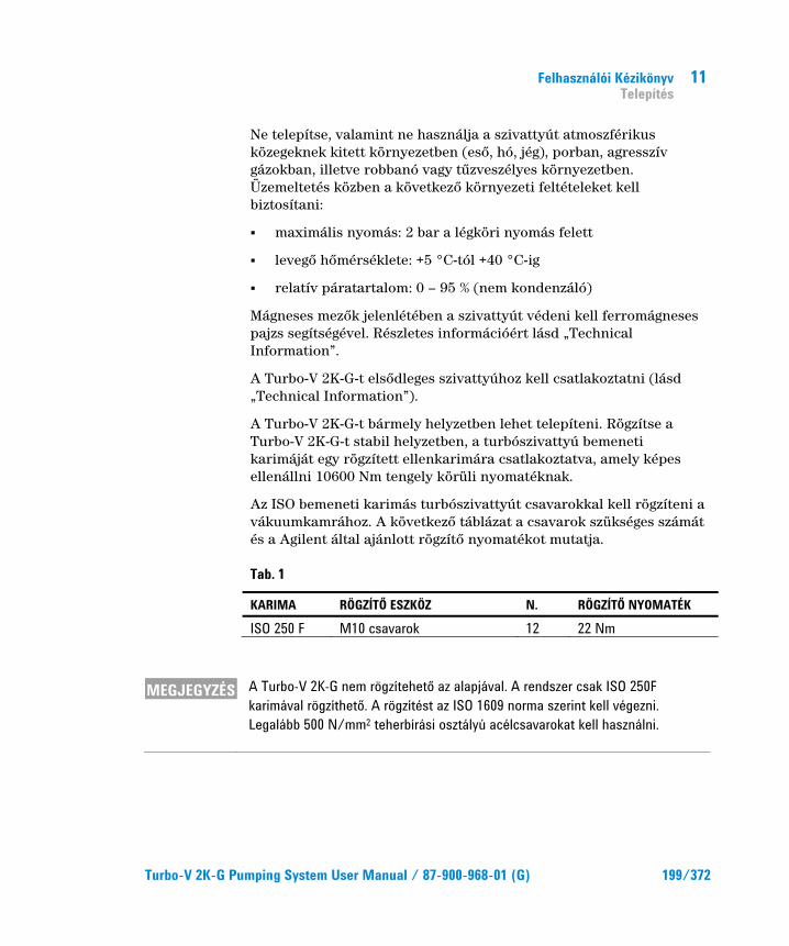
Felhasználói Kézikönyv Telepítés
11
Turbo-V 2K-G Pumping System User Manual / 87-900-968-01 (G) 199/372
Ne telepítse, valamint ne használja a szivattyút atmoszférikus közegeknek kitett környezetben (esŐ, hó, jég), porban, agresszív gázokban, illetve robbanó vagy tşzveszélyes környezetben. Üzemeltetés közben a következŐ környezeti feltételeket kell biztosítani:
� maximális nyomás: 2 bar a légköri nyomás felett
� levegŐ hŐmérséklete: +5 °C-tól +40 °C-ig
� relatív páratartalom: 0 – 95 % (nem kondenzáló)
Mágneses mezŐk jelenlétében a szivattyút védeni kell ferromágneses pajzs segítségével. Részletes információért lásd „Technical Information”.
A Turbo-V 2K-G-t elsŐdleges szivattyúhoz kell csatlakoztatni (lásd „Technical Information”).
A Turbo-V 2K-G-t bármely helyzetben lehet telepíteni. Rögzítse a Turbo-V 2K-G-t stabil helyzetben, a turbószivattyú bemeneti karimáját egy rögzített ellenkarimára csatlakoztatva, amely képes ellenállni 10600 Nm tengely körüli nyomatéknak.
Az ISO bemeneti karimás turbószivattyút csavarokkal kell rögzíteni a vákuumkamrához. A következŐ táblázat a csavarok szükséges számát és a Agilent által ajánlott rögzítŐ nyomatékot mutatja.
Tab. 1
KARIMA RÖGZÍTŊ ESZKÖZ N. RÖGZÍTŊ NYOMATÉK
ISO 250 F M10 csavarok 12 22 Nm
MEGJEGYZÉS A Turbo-V 2K-G nem rögzítehetŋ az alapjával. A rendszer csak ISO 250F karimával rögzíthetŋ. A rögzítést az ISO 1609 norma szerint kell végezni. Legalább 500 N/mm2 teherbírási osztályú acélcsavarokat kell használni.

11 Felhasználói Kézikönyv Telepítés
200/372 Turbo-V 2K-G Pumping System User Manual / 87-900-968-01 (G)
FIGYELEM! A Turbo-V 2K-G a második telepítési (vagy túlfeszültség) kategóriához tartozik az EN 61010-1 direktíva szerint. Csatlakoztassa az eszközt a fenti kategóriának megfelelŋ hálózathoz. A Turbo-V 2K-G-nek olyan bemeneti/kimeneti és soros kommunikációs csatlózásai vannak, amelyeket úgy kell külsŋ áramkörökhöz csatlakoztatni, hogy elektromos részek ne legyenek hozzáférhetŋk. Használja a mellékelt csatlakozókat az IP-54 védelmi fokozat fenntartásához. Gyŋzŋdjön meg róla, hogy a Turbo-V 2K-G-hez csatlakoztatott eszköz megfelelŋ egyes hiba esetén is az RN 61010-1 direktíva szerint.
Opcionális tartozékok telepítéséhez válassza a „Technical Information”.
Felhasználói Kézikönyv Használat
11
Turbo-V 2K-G Pumping System User Manual / 87-900-968-01 (G) 201/372
Használat Ez a bekezdés részletezi az alapvetŐ üzemeltetési eljárásokat. Végezze el az összes elektromos és pneumatikus csatlakoztatást a rendszer használata elŐtt.
A vákuumkamra melegítése közben a bemeneti szelep hŐmérséklete nem haladhatja meg a 80 °C-ot.
A szivattyú mşködtetésekor a rotor hŐmérséklete soha nem haladhatja meg a 120 °C-t. A felhasználónak ügyelnie kell, hogy a szivattyúzott gáz szerint beállítsa a helyes gázmódot. 1 az N2 és könnyebb gázokhoz, 0 az argonhoz (alapértelmezés). Részletekért lásd „Technical Information”.
VESZÉLY!
Soha ne használja a turbószivattyút, amikor a bemeneti karima nincs csatlakoztatva a vákuumkamrához vagy nincs kiiktatva. Ne érintse meg a turbószivattyút vagy annak tartozékait a melegítési folyamat közben. Magas hŋmérséklet égést okozhat.
FIGYELEM! Kerülje a szivattyú ütését, rázását vagy durva mozgatását üzem közben. A csapágyak megsérülhetnek. Használjon portól és szilárd részektŋl mentes levegŋt vagy közömbös gázt a szivattyú szellŋztetéséhez. A szellŋzŋ porton lévŋ nyomásnak 1 barnál kisebbnek kell lennie (a légköri nyomás fölött). A csapágyakra szennyezŋ vagy részecskéket tartalmazó gázok szivattyúzásához ezek a szivattyúk fel vannak szerelve egy olyan különleges porttal, amelyen keresztül a csapágyak védelme érdekében a szivattyúhoz közömbös gázt (Nitrogén vagy Hélium) kell áramoltatni (lásd „Technical Information” függelék).
FIGYELEM! A szivattyút soha ne használjuk olyan korrodáló gáz vagy gŋz jelenlétében használni, amely károsíthatja a szivattyú belsejében lévŋ anyagokat.
11 Felhasználói Kézikönyv Használat
202/372 Turbo-V 2K-G Pumping System User Manual / 87-900-968-01 (G)
VESZÉLY!
Amikor a szivattyút mérgezŋ, gyúlékony vagy radioaktív gázok szivattyúzására használja, kérem, kövesse az egyes gázok ártalmatlanításához szükséges eljárásokat. Ne használja a szivattyút robbanó gázok jelenlétében. A szivattyút N2, Ar és könnyebb gázok nagyteljesítményť szivattyúzásához tervezték. Ha az Ar-nél nehezebb gázokat kell szivattyúznia, kérem, információért forduljon a Agilent mťszaki támogatáshoz.
A Turbo-V 2K-G használata
A rendszer elindítása A rendszer elindítása elŐtt ellenŐrizze, hogy a B/K csatlakozó ki van-e húzva. Ha a rendszer távoli B/K-hoz van csatlakoztatva, ellenŐrizze, hogy stop jel (lásd „Technical Information” függelék "J1-REMOTE I/O" bekezdése) adva van-e.
A rendszer indításához kérem, kövesse a következŐ lépéseket:
1 húzza ki (ha jelen van) a rendszer B/K csatlakozóját
2 dugja be a tápkábelt
3 szivattyúzza le a vákuumkamrát 0.1 mbarra
4 adjon a Turbo-V 2K-G-nek start jelet a következŐ módszerek valamelyikével:
a a mellékelt B/K csatlakozó csatlakoztatása
b távoli start jel adása a B/K csatlakozón keresztül (lásd „Technical Information” függelék „J1 REMOTE I/O” bekezdése)
c távoli start jel adása az RS 232/485 soros interfészen keresztül (lásd „Technical Information” függelék „RS 232/485 kommunikáció leírása”).

Felhasználói Kézikönyv Használat
11
Turbo-V 2K-G Pumping System User Manual / 87-900-968-01 (G) 203/372
VESZÉLY!
Amikor a tápfeszültség rá van kapcsolva, és gyári 15 tťs csatlakozó csatlakoztatva van, a Turbo-V 2K-G automatikusan elindul.
FIGYELEM! A vezérlŋt már mechanikusan és elektromosan a szivattyúhoz csatlakoztatva szállítják. A vezérlŋnek a szivattyúról való leválasztását csak jogosult Agilent vákuumtechnológiai személyzet végezheti.
MEGJEGYZÉS Amikor legelŋször futtatja a Turbo-V 2K-G-t, a vezérlŋ egység automatikusan elindítja a rendszert egy különleges eljárással, amely védi a csapágyakat az esetleges sérülésektŋl (SOFT START). A rendszer lépésrŋl lépésre, fokozatosan indul teljes sebességig 10 perctŋl 1 órán belülig. Miután a rendszer elérte a teljes sebességet, a soft start eljárás le lesz tiltva, és a következŋ indítások szokásos úton történnek.
MEGJEGYZÉS Az IP 54 védelmi fokozat fenntartásához csak a szivattyúhoz mellékelt csatlakozókat szabad használni. Használjon PN 969-9957 vagy 969-9958 csatlakozót tápkábelhez, és rögzítse a vezérlŋhöz alkalmas tartóbilincs segítségével (lásd következŋ ábra). Ezt a kábelt és csatlakozó dugót megfelelŋen földelt csatlakozó aljazattal használja, hogy elkerülje az áramütés veszélyét, és eleget tegyen az EK normatíváiban lefektetett biztonsági követelményeknek.
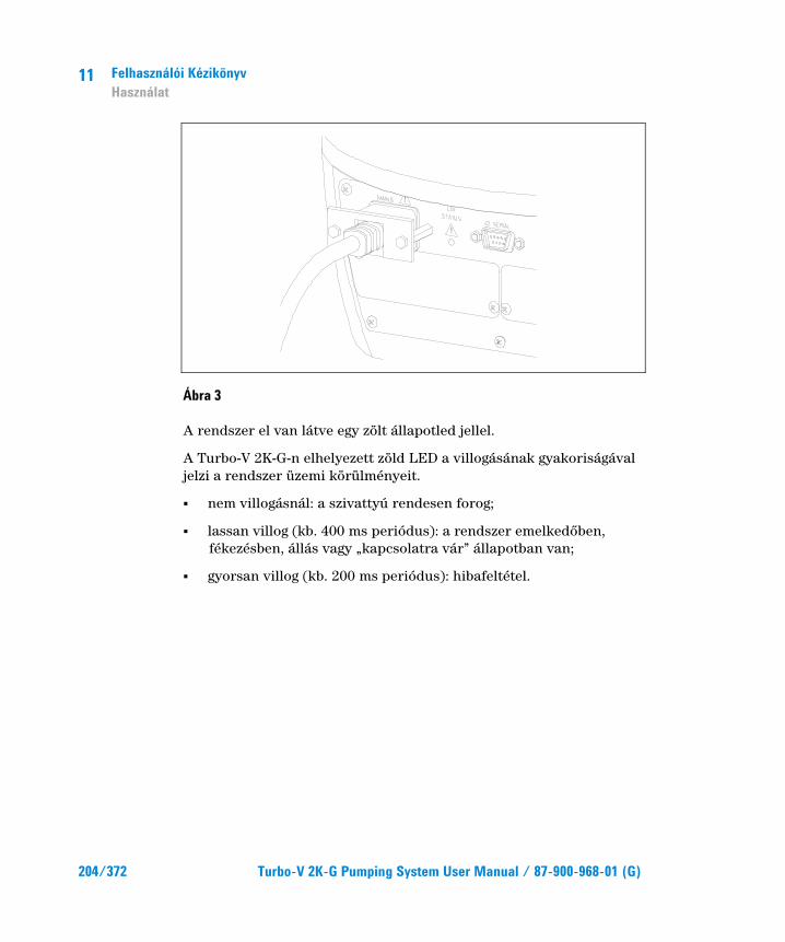
11 Felhasználói Kézikönyv Használat
204/372 Turbo-V 2K-G Pumping System User Manual / 87-900-968-01 (G)
Ábra 3
A rendszer el van látve egy zölt állapotled jellel.
A Turbo-V 2K-G-n elhelyezett zöld LED a villogásának gyakoriságával jelzi a rendszer üzemi körülményeit.
� nem villogásnál: a szivattyú rendesen forog;
� lassan villog (kb. 400 ms periódus): a rendszer emelkedŐben, fékezésben, állás vagy „kapcsolatra vár” állapotban van;
� gyorsan villog (kb. 200 ms periódus): hibafeltétel.

Felhasználói Kézikönyv Használat
11
Turbo-V 2K-G Pumping System User Manual / 87-900-968-01 (G) 205/372
A rendszer leállítása A szivattyú leállításához a következŐ módszerek egyikét használhatja:
1 a mellékelt B/K csatlakozó kihúzása
2 távoli stop jel adása a B/K csatlakozón keresztül (lásd „Technical Information” függelék „J1 REMOTE I/O” bekezdése)
3 távoli stop jel adása az RS 232/485 soros interfészen keresztül (lásd „Technical Information” függelék „RS 232/485 kommunikáció leírása”).
Vészleállítás A Turbo-V 2K-G vészhelyzetben való azonnali leállításához le kell kapcsolni a tápfeszültséget. Mindig figyelni kell arra, hogy ez a mşvelet, azonfelül, hogy teljesen kikapcsolja a szivattyú táplálását, kikapcsolja a controller minden egyéb funkcióját is, mint például a Purge és az EllenŐrzött Vent vezérlést és azt a képességet, hogy kommunikálni lehessen azzal a rendszerrel, ahová a szivattyú integrálták I/O, Seriale vagy Profibus útján.
Ezenfelül ez a mşvelet nem biztosíthatja a rotor azonnali leállását. Ennek forgási sebessége a rendszerben lévŐ vákuumszint függvényében fog csökkenni.
11 Felhasználói Kézikönyv Karbantartás
206/372 Turbo-V 2K-G Pumping System User Manual / 87-900-968-01 (G)
Karbantartás A Turbo-V 2K-G nem igényel karbantartást. A rendszeren végzett bármely munkát jogosult személyzetnek kell elvégeznie.
VESZÉLY!
A rendszeren bármely munka végzése elŋtt válassza le azt a tápfeszültségrŋl, szellŋztesse a szivattyút a megfelelŋ elektromos szelep kinyitásával, várjon, amíg a rotor forgása leáll, és amíg a szivattyú felületének hŋmérséklete 50 °C alá esik.
Meghibásodás esetén lépjen kapcsolatba a helyi Agilent szervizközponttal, ahol tudnak adni egy helyreállított rendszert a hibás helyett.
MEGJEGYZÉS Mielŋtt javításra vagy cserére visszaküldi a rendszert a gyártóhoz, az ehhez a gépkönyvhöz csatolt „Egészség és biztonság” lapot ki kell tölteni és el kell küldeni a helyi kereskedelmi irodához. A lap egy másolatát szállítás elŋtt be kell illeszteni a rendszercsomagba.
Ha a rendszert le kell selejtezni, azt ártalmatlanítani kell a konkrét nemzeti szabványoknak megfelelŐen.
Felhasználói Kézikönyv Megsemmisítés
11
Turbo-V 2K-G Pumping System User Manual / 87-900-968-01 (G) 207/372
Megsemmisítés A címkén jelenlévŐ "WEEE" logo jelentése. Az alább látható szimbólum az EK "WEEE" elnevezésş irányelvével összhangban kerül alkalmazásra. Ez a szimbólum (mely csak az Európai Közösség országaiban érvényes), azt jelzi, hogy a termék, melyen megtalálható, NEM kerülhet közönséges háztartási vagy ipari hulladékkal együtt megsemmisítésre, hanem azt egy szelektív hulladékgyşjtŐ rendszerbe kell továbbítani. A végfelhasználónak, a gyşjtési és megsemmisítési eljárás beindítása céljából, az adásvételi szerzŐdés határidŐinek és feltételeinek alapos áttanulmányozása után, fel kell vennie a kapcsolatot a berendezés szállítójával, legyen ez a gyártó vagy egy viszonteladó.

11 Felhasználói Kézikönyv Megsemmisítés
208/372 Turbo-V 2K-G Pumping System User Manual / 87-900-968-01 (G)

Turbo-V 2K-G Pumping System User Manual
209/372
12 Podrecznik Instrukcji Wskazówki dotyczĈce bezpieczeľstwa dla Pomp
Turbomolekularnych 210 Informacje ogolne 211 Magazynowanie 213 Przygotowanie do instalacji 214 Instalacja 216 Uůytkowanie 219 Uůytkowanie Turbo-V 2K-G 220 Jak uruchomiý system 220 Jak zatrzymaý Turbo-V 2K-G 223 Zatrzymanie Alarmowe 223 Konserwacja 224 Przetworstwo odpadow 225 Tãumaczenie instrukcji oryginalnej

12 Podrecznik Instrukcji Wskazówki dotyczĈce bezpieczeľstwa dla Pomp Turbomolekularnych
210/372 Turbo-V 2K-G Pumping System User Manual / 87-900-968-01 (G)
Wskazówki dotyczĈce bezpieczeľstwa dla Pomp Turbomolekularnych
Pompy Turbomolekularne opisane w niniejszej Instrukcji ObsŊugi posiadajIJ wysokIJ iloŕij energii kinetycznej spowodowanej bardzo wysokIJ prľdkoŕciIJ obrotowIJ razem z masIJ wŊaŕciwIJ wirników.
W przypadku uszkodzenia systemu, na przykŊad z powodu kontaktu miľdzy wirnikiem a stojanem lub z powodu pľkniľcia wirnika, energia obrotowa moŨe byij zwolniona.
ZAGROZENIE!
Aby uniknĈý uszkodzenia aparatury i zapobiec uszkodzeniom ciaãa operatorów, naleůy obowiĈzkowo przestrzegaý zaleceľ dotyczĈcych instalacji opisanych w niniejszej instrukcji obsãugi!

Podrecznik Instrukcji Informacje ogolne
12
Turbo-V 2K-G Pumping System User Manual / 87-900-968-01 (G) 211/372
Informacje ogolne Ta aparatura jest przeznaczona do uŨytku zawodowego. UŨytkownik musi przeczytaij bardzo uwaŨnie niniejszIJ instrukcjľ kaŨdIJ dodatkowIJ informacjľ dostarczonIJ przez firmľ Agilent przed uŨytkowaniem aparatury. Firma Agilent uchyla siľ od jakiejkolwiek odpowiedzialnoŕci w przypadku czľŕciowego lub caŊkowitego braku przestrzegania instrukcji, w przypadku niewŊaŕciwego uŨytkowania przez nieprzeszkolony personel, w przypadku nieupowaŨnionych interwencji jak i w przypadku braku zastosowania odpowiednich norm krajowych.
System Turbo-V 2K-G jest zintegrowanym systeme skŊadajIJcym siľ z pompy turbomolekularnej dla zastosowaŋ wysokich i ultra wysokich próŨni jak i przez odpowiedni system sterowania tzw. kontroler. System jest w stanie pompowaij wiele typów gazu lub mieszanek gazowych, ale nie jest przystosowany do pompowania pŊynów lub staŊych czIJstek.
Zjawisko pompowania jest uzyskane poprzez obrotowIJ turbinľ o wysokiej prľdkoŕci (max. 33000 obr./min) napľdzanIJ przez elektryczny silnik trójfazowy o wysokiej wydajnoŕci. Turbo-V 2K-G jest caŊkowicie bez czynników zanieczyszczajIJcych, i dlatego teŨ jest odpowiedni do zastosowaŋ gdzie jest wymagana tzw.”czysta” próŨnia.
Poza tym, posiada pomocnicze konektory poprzez które moŨliwe jest zdalne pilotowanie go przy pomocy gŊównego komputera poŊIJczonego z liniIJ szeregowIJ (port RS232 lub RS485).
W nastľpnych paragrafach zostaŊy przedstawione wszystkie potrzebne informacje w celu zagwarantowania bezpieczeŋstwa operatora podczas uŨytkowania aparatury. SzczegóŊowe informacje zostaŊy przedstawione w dodatku dotyczIJcym informacji technicznych „Technical Information”.

12 Podrecznik Instrukcji Informacje ogolne
212/372 Turbo-V 2K-G Pumping System User Manual / 87-900-968-01 (G)
W tej instrukcji zastosowano nastľpujIJce umowne znaczenia:
ZAGROZENIE!
Komunikaty niebezpieczeľstwa przyciĈgajĈ uwagĘ operatora co do danej procedury lub danego postĘpowania którego nieprawidãowe wykonanie mogãoby spowodowaý powaůne uszkodzenia ciaãa.
UWAGA! Komunikaty zwiĘkszonej uwagi sĈ wyœwietlane przed procedurami i w przypadku ich braku przestrzegania, moůe dojœý do uszkodzenia aparatury.
PRZYPIS SĈ to waůne informacje wyciĈgniĘte z tekstu.

Podrecznik Instrukcji Magazynowanie
12
Turbo-V 2K-G Pumping System User Manual / 87-900-968-01 (G) 213/372
Magazynowanie W celu zagwarantowania najwyŨszego poziomu funkcjonalnego i niezawodnoŕci pomp turbomolekularnych Agilent , muszIJ byij przestrzegane nastľpujIJce zalecenia:
� podczas transportu, przesuniľcia i magazynowania pomp, nie mogIJ byij przekroczone nastľpujIJce warunki ŕrodowiskowe:
� temperatura: od –20 °C do 70 °C
� wilgotnosc wzgledna: od 0 do 95 % (bez opar)
� klient po otrzymaniu i przygotowaniu po raz pierwszy pomp turbomolekularnych, musi je zawsze uruchomiij w sposób Soft-Start
� czas magazynowania danej pompy turbomolekularnej wynosi 10 miesiľcy od daty wysyŊki.
UWAGA! Jeůeli z jakiegokolwiek powodu, czas magazynowania jest dãuůszy, naleůy odesãaý pompĘ do fabryki. W celu jakiejkolwiek informacji, prosimy skontaktowaý siĘ z miejscowym przedstawicielem firmy Agilent.
12 Podrecznik Instrukcji Przygotowanie do instalacji
214/372 Turbo-V 2K-G Pumping System User Manual / 87-900-968-01 (G)
Przygotowanie do instalacji System Turbo-V 2K-G jest dostarczany w specjanym ochronnym opakowaniu; w przypadku ŕladów uszkodzeŋ do których mogŊoby dojŕij podczas transportu, naleŨy skontaktowaij siľ z miejscowym biurem sprzedaŨy.
Podczas operacji rozpakowywania, naleŨy zwróciij szczególnIJ uwagľ aby nie spowodowaij upadku systemu Turbo-V 2K-G ani nie poddawaij go uderzeniom lub wibracjom.
ZdjIJij obudowľ konektorów tylko wtedy, gdy turbopompa zostaŊa przymocowana do systemu.
Z powodu jego ciľŨaru (35 kg) aby wyciIJgnIJij pompľ z opakowania, naleŨy zastosowaij trzy zaczepy na 120° wkrľcone na korpusie pompy.
Nie porzucaij opakowania w ŕrodowisku. MateriaŊ ten nadaje siľ caŊkowicie do recyklingu zgodny jest z dyrektywIJ UE 855/399 dotyczIJcej ochrony ŕrodowiska.
UWAGA! Aby uniknĈý problemów odgazowywania, naleůy nie dotykaý goãymi rĘkoma czĘœci przeznaczonych do próůni. Naleůy zawsze stosowaý odpowiednie rĘkawice ochronne lub odpowiednie zabezpieczenie.
PRZYPIS Turbo-V 2K-G nie moůe byý uszkodzony poprzez wystawienie go na dziaãanie atmosfery. Zaleca siĘ aby pompa do momentu jej instalacji na systemie, pozostaãa dobrze zamkniĘta. Jest to w celu zabezpieczenia przed zanieczyszczeniem systemu.
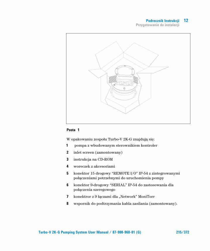
Podrecznik Instrukcji Przygotowanie do instalacji
12
Turbo-V 2K-G Pumping System User Manual / 87-900-968-01 (G) 215/372
Posta 1
W opakowaniu zespoŊu Turbo-V 2K-G znajdujIJ siľ:
1 pompa z wbudowanym sterownikiem kontroler
2 inlet screen (zamontowany)
3 instrukcja na CD-ROM
4 woreczek z akcesoriami
5 konektor 15 drogowy “REMOTE I/O” IP-54 z zintegrowanymi poŊIJczeniami potrzebnymi do uruchomienia pompy
6 konektor 9-drogowy “SERIAL” IP-54 do zastosowania dla poŊIJczenia szeregowego
7 konektror z 9 ŊIJczami dla „Network” MoniTorr
8 wspornik do podtrzymania kabla zasilania (zamontowany).

12 Podrecznik Instrukcji Instalacja
216/372 Turbo-V 2K-G Pumping System User Manual / 87-900-968-01 (G)
Instalacja
ZAGROZENIE!
Pompa z powodu wãasnego ciĘůaru, musi byý przemieszczana poprzez odpowiedni sprzĘt do tego celu. Do tego celu naleůy zastosowaý odpowiednie zawiesia wkrĘcone w gwintowane otwory znajdujĈce siĘ na korpusie pompy.
UWAGA! Nie zdejmowaý zamocowanej œrubami pokrywy przed podãĈczeniem turbopompy do systemu.
UWAGA! ZdjĈý obudowĘ konektorów tylko wtedy, gdy turbopompa zostaãa przymocowana do systemu.
Figuur 4
Nie instalowaij i / lub uŨytkowaij pompy w otoczeniach wystawionych na czynniki atmosferyczne (deszcz, mróz, ŕnieg), pyŊy, gazy chemiczne, w ŕrodowiskach wybuchowych lub z wysokim zagroŨeniem poŨaru.
WA
RN
ING
REMOVE THIS PROTECTION AFTER
MECHANICAL INSTALLATION
NO
CHAMBER
YES

Podrecznik Instrukcji Instalacja
12
Turbo-V 2K-G Pumping System User Manual / 87-900-968-01 (G) 217/372
Podczas dziaŊania obowiIJzkowo naleŨy przestrzegaij nastľpujIJce warunki otoczenia:
� maksymalne ciŕnienie: 2 bary ponad ciŕnieniem atmosferycznym
� temperatura powietrza: od +5 °C do +40 °C
� wzglľdna wilgoij 0 – 95 % (bez opar).
W obecnoŕci pól elektromagnetycznych pompa musi byij odpowiednio zabezpieczona przez odpowiednie ekranowanie. W celu szczegóŊowego zapoznania siľ z tematem patrz dodatek “Technical Information”
Turbo-V 2K-G musi byij podŊIJczony do gŊównej pompy (patrz schemat w “Informacjach Technicznych”)
Turbo-V 2K-G moŨe byij zainstalowany w jakiejkolwiek pozycji . Zamocowaij Turbo-V 2K-G w stabilnej pozycji, ŊIJczIJc koŊnierz wejŕciowy turbopompy do koŊnierza staŊego wytrzymaŊego na obciIJŨenie 10600 Nm wokóŊ wŊasnej osi.
Turbopompa z koŊnierzem wejŕciowym ISO musi byij zamocowana do komory próŨniowej poprzez ŕruby mocujIJce. Niniejsza tabela opisuje iloŕij potrzebnych ŕrub i na jaki moment, zalecany przez firmľ Agilent, naleŨy je dokrľciij.
Tab. 1
KOâNIERZ TYP MOCOWANIA Nr. MOMENT DOKRėCENIA
ISO 250 F Œruba mocujĈca z gwintem M10 12 22 Nm
PRZYPIS Turbo-V 2K-G nie moůe byý zamocowany poprzez wãasnĈ podstawĘ. System moůe byý zamocowany tylko poprzez wãasny koãnierz ISO 250 F. Mocowanie musi byý zrealizowane zgodnie z normĈ ISO 1609. MuszĈ byý zastosowane œruby mocujĈce ze stali z klasĈ wytrzymaãoœci co najmniej 500 N/mm2.

12 Podrecznik Instrukcji Instalacja
218/372 Turbo-V 2K-G Pumping System User Manual / 87-900-968-01 (G)
UWAGA! Turbo-V 2K-G naleůy do drugiej kategorii instalacji (lub nadnapiĘcia) przewidzianej przez normĘ EN 61010-1. Dlatego teů podãĈczyý urzĈdzenie do linii zasilania która speãni te wymogi. Zastosowaý konektory na wyposaůeniu aby zagwarantowaý odizolowanie IP-54. Turbo-V 2K-G posiada konektory wejœciowe/ wyjœciowe i dla komunikacji szeregowej które muszĈ byý podãĈczone do obwodów zewnĘtrznych w sposób aby ůadna czĘœý znajdujĈca siĘ pod napiĘciem nie mogãa byý dostĘpna. Naleůy upewniý siĘ ůe izolacja podãĈczonego urzĈdzenia do Turbo-V 2K-G, posiada odpowiednie odizolowanie nawet w stanie pojedynczej usterki zgodnie z wymaganiami normy EN 61010-1.
Aby zainstalowaij opcjonalne akcesoria, naleŨy zapoznaij siľ z „Technical Information”.

Podrecznik Instrukcji Uůytkowanie
12
Turbo-V 2K-G Pumping System User Manual / 87-900-968-01 (G) 219/372
Uůytkowanie W tym paragrafie zostaŊy przedstawione gŊówne procedury operacyjne.
Przed zastosowaniem systemu naleŨy wykonaij wszystkie poŊIJczenia elektryczne i pneumatyczne.
Podczas ewentualnego nagrzania komory próŨniowej, temperatura na koŊnierzu nie moŨe przekroczyij 80 °C.
Podczas dziaŊania pompy, temperatura wirnika nie moŨe nigdy przekroczyij 120 °C.
Operator musi upewniij siľ Ũe urzIJdzenie jest przygotowane do prawidŊowego sposobu dziaŊania w zaleŨnoŕci od gazu do pompowania: 1 dla Azotu i lekkich gazów, 0 dla Argonu (tryb default). W celu dodatkowych informacji naleŨy zapoznaij siľ z dodatkiem “Technical Information”
ZAGROZENIE!
Nigdy nie naleůy uruchomiý pompĘ w przypadku kiedy koãnierz wejœciowy nie jest podãĈczony do komory lub nie jest zamkniĘty z koãnierzem zamkniĘcia. Nie dotykaý turbopompy i jej ewentualnych akcesoriów podczas operacji nagrzewania. Wysoka temperatura moůe spowodowaý uszkodzenia ciaãa na osobach.
UWAGA! Unikaý uderzeľ, wahaľ lub gwaãtownych przesuniĘý turbopompy podczas jej dziaãania. MogĈ uszkodziý siĘ ãoůyska. Dla wlotu do powietrza pompy zastosowaý powietrze lub obojĘtny gaz bez pyãu lub innych czĈstek. Ciœnienie wejœciowe poprzez odpowiedni wlot musi byý niůsze od 1 bara (ponad ciœnienie atmosferyczne). Aby moůliwe byão pompowanie gazów, zawierajĈcych czĈsteczki lub zanieczyszczenia niszczĈce ãoůyska, pompy te sĈ wyposaůone w odpowiedi wlot, poprzez który naleůy dostarczyý pompie przepãyw obojĘtnego gazu (Azot i Hel) dla zabezpieczenia ãoůysk (Patrz dodatek “Technical Information”).

12 Podrecznik Instrukcji Uůytkowanie
220/372 Turbo-V 2K-G Pumping System User Manual / 87-900-968-01 (G)
UWAGA! Absolutnie nie wolno stosowaý pompy w obecnoœci gazów lub oparów korozyjnych, poniewaů mogĈ one byý przyczynĈ uszkodzenia wewnĘtrznych elementów pompy.
ZAGROZENIE!
Kiedy pompa jest zastosowana do pompowania gazów toksycznych, ãatwo palnych lub radioaktywnych, naleůy wykonaý odpowiednie procedury typowe dla kaůdego z gazów. Nie stosowaý pompy w obecnoœci gazów wybuchowych. Pompa jest zaprojektowana aby posiadaãa wysoki przepãyw Azotu, Argonu i innych lůejszych gazów. W przypadku kiedy zaistnieje potrzeba pompowania ciĘůszych gazów od Argonu, w celu informacji, naleůy skontaktowaý siĘ z Serwisem Technicznym firmy Agilent.
Uůytkowanie Turbo-V 2K-G
Jak uruchomiý system Przed uruchomieniem systemu, naleŨy skontrolowaij czy konektor I/O jest zdjľty. JeŨeli system jest podŊIJczony do zdalnego urzIJdzenia wejŕij wyjŕij Input/Output , naleŨy upewniij siľ Ũe sygnaŊ STOP jest aktywny (patrz paragraf „J1 – ZDALNE I/O” w dodatku „Technical Information”).
Aby uruchomiij system naleŨy wykonaij nastľpujIJce czynnoŕci:
1 zdjIJij (jeŕli jest obecny) konektor I/O
2 podŊIJczyij zasilanie sieci
3 doprowadziij ciŕnienie wewnIJtrz komory próŨniowej na wartoŕij 0,1 mbar
4 dostraczyij do Turbo-V 2K-G sygnaŊ STARTU w jeden z nastľpujIJcych sposobów:
a podŊIJczyij konektor I/O na wyposaŨeniu

Podrecznik Instrukcji Uůytkowanie
12
Turbo-V 2K-G Pumping System User Manual / 87-900-968-01 (G) 221/372
b podaij sygnaŊ START zdalnie poprzez konektor I/O (patrz paragraf "J1 – ZDALNE I/O" w dodatku "Technical Information")
c podaij sygnaŊ START zdalnie poprzez interfejs szeregowy RS 232/485 (patrz paragraf "RS 232/485 Opis Komunikacji" w dodatku "Technical Information").
ZAGROZENIE!
Kiedy zostanie dostarczone zasilanie i konektor 15 – ãĈczy na wyposaůeniu jest podãĈczony, Turbo-V 2K-G uruchomi siĘ automatycznie.
UWAGA! Sterownik kontroler jest dostarczony juů poãĈczony mechanicznie i elektrycznie do pompy. Odseparowanie kontrolera od korpusu pompy moůe byý tylko wykonane przez personel upowaůniony przez firmĘ Agilent Vacuum Technologies.
PRZYPIS Kiedy uruchamia siĘ Turbo-V 2K-G po raz pierwszy, kontroler automatycznie uruchamia system ze specjalnĈ procedurĈ która chroni ãoůyska przed moůliwym ich uszkodzeniem (SOFT START). System zostanie uruchomiony kolejnymi fazami aů do uzyskania peãnej prĘdkoœci w przeciĈgu odpowiedniego czasu który waha siĘ od 10 minut do 1 godziny. Po osiĈgniĘciu peãnej prĘdkoœci przez system, procedura „soft start” zostaje wyãĈczona i kolejne uruchomienia odbywajĈ siĘ w normalny sposób.
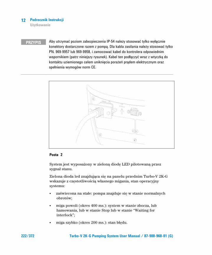
12 Podrecznik Instrukcji Uůytkowanie
222/372 Turbo-V 2K-G Pumping System User Manual / 87-900-968-01 (G)
PRZYPIS Aby utrzymaý poziom zabezpieczenia IP-54 naleůy stosowaý tylko wyãĈcznie konektory dostarczone razem z pompĈ. Dla kabla zasilania naleůy stosowaý tylko PN. 969-9957 lub 969-9958, i zamocowaý kabel do kontrolera odpowiednim wspornikiem (patrz niniejszy rysunek). Kabel ten podãĈczyý wraz z wtyczkĈ do kontaktu uziemionego celem unikniĘcia poraůeľ prĈdem elektrycznym oraz speãnienia wymogów norm CE.
Posta 2
System jest wyposaŨony w zielonIJ diodľ LED pilotowanIJ przez sygnaŊ stanu.
Zielona dioda led znajdujIJca siľ na panelu przednim Turbo-V 2K-G wskazuje z czľstotliwoŕciIJ wŊasnego migania, stan operacyjny systemu:
� zaŕwiecona na staŊe: pompa znajduje siľ w stanie normalnych obrotów;
� miga powoli (okres 400 ms.): system w stanie zbocza, lub hamowania, lub w stanie Stop lub w stanie “Waiting for interlock”;
� miga szybko (okres 200 ms.): stan bŊľdu.
Podrecznik Instrukcji Uůytkowanie
12
Turbo-V 2K-G Pumping System User Manual / 87-900-968-01 (G) 223/372
Jak zatrzymaý Turbo-V 2K-G Aby zatrzymaij pompľ moŨna zastosowaij jeden z niniejszych sposobów:
1 wyjmujIJc konektor I/O na wyposaŨeniu
2 przesyŊajIJc sygnaŊ STOPU zdalnie poprzez konektor I/O (patrz paragraf "J1 – ZDALNE I/O" w dodatku "Technical Information")
3 przesyŊajIJc sygnaŊ STOPU zdalnie poprzez interfejs szeregowy RS 232/485 (patrz paragraf "RS 232/485 Opis Komunikacji" w dodatku "Technical Information").
Zatrzymanie Alarmowe Aby zatrzymaij natychmiast w stanie alarmowym zespóŊ Turbo-V 2K-G naleŨy odŊIJczyij kabel od zasilania. W zwiIJzku z tym naleŨy pamiľtaij, Ũe ta operacja nie tylko zupeŊnie odcina zasilanie pompy, ale wyŊIJcza równieŨ wszystkie inne funkcje sterownika, na przykŊad: nadzorowanie kontrolowanych funkcji “Purge” i “Vent” oraz moŨliwoŕij komunikowania siľ z ukŊadem, do którego pompa zostaŊa wbudowana, za poŕrednictwem I/Os, linii szeregowej lub Profibus.
Ponadto ta operacja nie moŨe zagwarantowaij natychmiastowego zatrzymania wirnika, którego prľdkoŕij bľdzie siľ zmniejszaŊa w zaleŨnoŕci od stopnia próŨni w ukŊadzie.
12 Podrecznik Instrukcji Konserwacja
224/372 Turbo-V 2K-G Pumping System User Manual / 87-900-968-01 (G)
Konserwacja ZespóŊ Turbo-V 2K-G nie wymaga Ũadnej konserwacji. Jakakolwiek interwencja musi byij wykonana przez upowaŨniony personel.
ZAGROZENIE!
Przed przystapieniem do jakiejkolwiek interwencji w systemie nalezy odlaczyc go od zrodla zasilania., otworzyc odpowiedni zawor pompy odczekac az wirnik sie zatrzyma calkowicie i temperatura powierzchni obudowy pompy obnizy sie ponizej 50 °C.
W przypadku usterki moŨliwe jest skorzystanie z serwisu naprawczego Agilent lub "Agilent advanced exchange service",który pozwoli na uzyskanie zregenerowanego systemu w zastľpstwie uszkodzonego systemu.
PRZYPIS Przed wysyãkĈ do konstruktora systemu do naprawy lub advanced exchange service, naleůy obowiĈzkowo wypeãniý i przekazaý do miejscowego biura sprzedaůy kartĘ „Bezpieczeľstwo i Zdrowie” zaãĈczonĈ do niniejszej instrukcji. Jeden egzemplarz –kopia- karty musi byý wãoůony do opakowania systemu przed jego wysyãkĈ.
JeŨeli system musi byij poddany rozbiórce, naleŨy przystIJpiij do jego eliminacji zgodnie z obowiIJzujIJcymi krajowymi normami w meritum sprawy.
Podrecznik Instrukcji Przetworstwo odpadow
12
Turbo-V 2K-G Pumping System User Manual / 87-900-968-01 (G) 225/372
Przetworstwo odpadow Objasnienie znajdujacego sie na etykiecie znaczenia logo “WEEE”. Uzyty ponizej symbol jest zgodny z wymogiem zarzadzenia “WEEE” Unii Europejskiej. Symbol ten (prawomocny tylko w krajach Unii Europejskiej) oznacza, ze wyrob ktory nim zostal oznaczony NIE moze byc przetworzony jako odpad razem z innymi domowymi lub przemyslowymi natomiast musi byc skladowany w miejscu przeznaczonym dla odpadow do przerobki zroznicowanej . Dlatego tez poleca sie uzytkownikowi, , po uprzedniej weryfikacji terminu i warunkow zawartych w kontrakcie sprzedazy, nawiazac kontakt z dostawca lub sprzedawca urzadzenia w celu uruchomienia procesu zbiorki i przerobu.

12 Podrecznik Instrukcji Przetworstwo odpadow
226/372 Turbo-V 2K-G Pumping System User Manual / 87-900-968-01 (G)
Turbo-V 2K-G Pumping System User Manual
227/372
13 Návod k Použití Bezpeÿnostní návod pro Turbomolekulární vývĚvy 228 Všeobecné informace 229 UskladnĚní 231 Pőíprava k instalaci 232 Instalace 234 Použití 237 Používání zaőízení Turbo-V 2K-G 238 Jak se zaőízení uvádí do provozu 238 Jak se zaőízení zastavuje 241 Nouzové zastavení 241 Údržba 242 Likvidace 243 Pőeklad originálního návodu
13 Návod k Použití Bezpeÿnostní návod pro Turbomolekulární vývĚvy
228/372 Turbo-V 2K-G Pumping System User Manual / 87-900-968-01 (G)
Bezpeÿnostní návod pro Turbomolekulární vývĚvy Turbomolekulární vývĺvy, jak jsou popisovány v následujícím návodu, obsahují velké množství kinetické energie díky vysoké otáĵivé rychlosti v kombinaci s konkrétním objemem jejich rotorŞ.
V pœípadĺ systémové nefunkĵnosti, napœ. kontaktu rotoru anebo statoru nebo pœi zhroucení rotoru mŞže dojít k uvolnĺní rotaĵní energie.
NEBEZPEþÍ!
Pokyny k instalaci uvedené v tomto návodu musí být pőísnĚ dodržovány za úÿelem prevence poškození zaőízení a zranĚní obsluhy!

Návod k Použití Všeobecné informace
13
Turbo-V 2K-G Pumping System User Manual / 87-900-968-01 (G) 229/372
Všeobecné informace Toto zaœízení je urĵeno pro odborníky. Uživatel by si mĺl pœed použitím zaœízení pœeĵíst tento návod a všechny další informace dodané firmou Agilent. Firma Agilent neodpovídá za jakékoli nehody, které vzniknou následkem i ĵásteĵného nedodržení tĺchto pokynŞ, nesprávným používáním neznalými osobami, neoprávnĺným zásahem do zaœízení nebo jakoukoli ĵinností, která je v rozporu s pokyny uvedenými v pœíslušných státních normách.
Vývĺva Turbo-V 2K-G je integrovaný systém s turbomolekulární vývĺvou a pœíslušným regulátorem pro takové aplikace, kde se požaduje vysoké a velmi vysoké vakuum. Zaœízení mŞže odĵerpávat libovolný plyn nebo plynnou smĺs. Není vhodné na ĵerpání tekutin nebo pevných ĵástic. øerpání zajišřuje velmi rychlá turbína (max. 33000 ot/min.) pohánĺná vysoce výkonným trojfázovým elektromotorem. Zaœízení Turbo-V2K-G neobsahuje žádné kontaminující látky a proto se hodí pro aplikace vyžadující "ĵisté" vakuum.
Je vybaveno pœídavnými konektory, aby bylo možné jej ovládat ze vzdáleného místa pomocí hostitelského poĵítaĵe prostœednictvím sériové linky (RS232 nebo RS485).
Následující odstavce obsahují informace potœebné k zajištĺní bezpeĵnosti obsluhy pœi používání tohoto zaœízení. Podrobné informace jsou uvedeny v pœíloze "Technical Information".
13 Návod k Použití Všeobecné informace
230/372 Turbo-V 2K-G Pumping System User Manual / 87-900-968-01 (G)
Tento manuál používá následující standardní protokol:
NEBEZPEþÍ!
Nebezpeÿí hlášení jsou urÿena pro upozornĚní obsluhy na urÿitý postup nebo ÿinnosti, které by v pőípadĚ nedodržení mohly zpţsobit vážný úraz.
POZOR! Pozor hlášení jsou uvedena pőed postupy, které by v pőípadĚ nedodržení mohly poškodit zaőízení.
POZNÁMKA Poznámky obsahují dţležité informace pőevzaté z textu.

Návod k Použití UskladnĚní
13
Turbo-V 2K-G Pumping System User Manual / 87-900-968-01 (G) 231/372
UskladnĚní Aby byla zajištĺna maximální provozuschopnost a spolehlivost turbomolekulárních vývĺv firmy Agilent, musíte dodržovat následující pokyny:
� Pœi pœepravĺ, pœemísřování a skladování vývĺv byste nemĺli pœekraĵovat následující technické podmínky prostœedí:
� Teplotní rozpĺtí : -20 °C až 70 °C
� Rozpĺtí vlhkosti: 0 až 95% (bez srážení)
� turbomolekulární vývĺvy musí uživatel po dodávce a poprvé vždycky spouštĺt pozvolnĺ
� skladovatelnost turbomolekulární vývĺvy je 10 mĺsícŞ ode dne doruĵení.
POZOR! Pokud dojde z jakéhokoli dţvodu k pőekroÿení skladovací lhţty, vývĚvu musíte vrátit výrobci. Informujte se prosím u místního zástupce pro prodej a servis vývĚv firmy Agilent.

13 Návod k Použití Pőíprava k instalaci
232/372 Turbo-V 2K-G Pumping System User Manual / 87-900-968-01 (G)
Pőíprava k instalaci Zaœízení Turbo-V 2K-G se dodává ve speciálním ochranném obalu. Pokud toto balení vykazuje známky poškození, k nĺmuž mohlo dojít bĺhem pœepravy, kontaktujte vaši místní prodejní poboĵku.
Pœi vybalování dávejte pozor, aby zaœízení nespadlo a chraŌte jej pœed všemi nenadálými nárazy, otœesy nebo vibracemi.
Odejmĺte zakrytí konektorŞ až poté, co bude turbovývĺva pœipevnĺná k systému.
Pro vyjmutí vývĺvy z obalu a také kvŞli jeho hmotnosti (35 kg) použijte tœi šrouby s okem našroubované na tĺlese vývĺvy s rozteĵí 120°.
Balicí materiál nelikvidujte nedovoleným zpŞsobem. Tento materiál lze 100% recyklovat a splŌuje požadavky smĺrnice EEC 85/399.
POZOR! Aby se zamezilo problémţm s odplyłováním, nepoužívejte holé ruce pői manipulaci s komponenty, které budou vystaveny vakuu. Vždy používejte rukavice nebo jinou vhodnou ochranu.
POZNÁMKA V normálním prostőedí se vývĚva Turbo-V 2K-G nemţže poškodit. Pőesto doporuÿujeme, abyste ji nechali zakrytou, dokud nebude nainstalována do systému. Tím se zamezí zneÿištĚní tohoto zaőízení.

Návod k Použití Pőíprava k instalaci
13
Turbo-V 2K-G Pumping System User Manual / 87-900-968-01 (G) 233/372
Postava 1
Balení Turbo-V 2K-G obsahuje:
1 ĵerpadlo s vestavĺným regulátorem
2 vstupní síto (namontováno)
3 tento návod k použití na CD-ROM
4 brašna s pœíslušenstvím
5 15-pólový konektor IP 54 pro pœipojení ke konektor "REMOTE I/O" (dálkové vstupy a výstupy) s veškerým propojením nezbytným pro spuštĺní ĵerpadla
6 9-kolíkový konektor IP-54 pro pœipojení ke konektoru "SERIAL", který se použije k sériovému pœipojení
7 9-kolíkový konektor pro pœipojení zaœízení "Network" Moni Torr
8 Pœíchytka pro uchycení napájecího kabelu (namontována).

13 Návod k Použití Instalace
234/372 Turbo-V 2K-G Pumping System User Manual / 87-900-968-01 (G)
Instalace
NEBEZPEþÍ!
Kvţli své hmotnosti je tőeba pői manipulaci s vývĚvou používat odpovídající nástroje a náőadí. Používejte pőíslušné šrouby s okem našroubované do otvorţ v tĚlese vývĚvy.
POZOR!
Pőed pőipojením turbomolekulární vývĚvy do systému nesundávejte šroubovací víko.
POZOR! OdejmĚte zakrytí konektorţ až poté, co bude turbovývĚva pőipevnĚná k systému.
Postava 2
Vývĺvu neinstalujte v prostœedí, které je vystaveno atmosférickým vlivŞm (déšř, sníh, led), prachu, agresivním plynŞm, ve výbušném prostœedí nebo v prostœedí s vysokým nebezpeĵím požáru. Za provozu je tœeba dodržovat následující podmínky dané prostœedím:
� maximální tlak: 2 bary nad atmosférickým tlakem
WA
RN
ING
REMOVE THIS PROTECTION AFTER
MECHANICAL INSTALLATION
NO
CHAMBER
YES

Návod k Použití Instalace
13
Turbo-V 2K-G Pumping System User Manual / 87-900-968-01 (G) 235/372
� teplota vzduchu: od +5 °C do +40 °C
� relativní vlhkost: 0 – 95 % (bez srážení)
V pœítomnosti magnetických polí se vývĺva musí chránit feromagnetickým stínĺním. Viz podrobné informace v pœíloze "Technical Information".
Vývĺva Turbo-V 2K-G se musí pœipojit k primárnímu ĵerpadlu (viz "Technical Information").
Vývĺvu Turbo-V 2K-G lze instalovat v libovolné poloze. Vývĺvu Turbo-V 2K-G upevnĺte v nĺjaké stabilní poloze a pœívodní pœírubu turbovývĺvy pœipojte k pevné protipœírubĺ, která snese torzní moment 10600 Nm kolem své osy.
Turbomolekulární vývĺva se vstupní pœírubou ISO se musí pœipevnit k vakuové komoœe šrouby. Následující tabulka uvádí nezbytný poĵet šroubŞ a pœíslušný utahovací moment, který doporuĵuje firma Agilent..
Tab. 1
PŐÍRUBA PŐÍCHYTNÉ ZAŐÍZENÍ POþET UTAHOVACÍ MOMENT
ISO 250 F šrouby M10 12 22 Nm
POZNÁMKA VývĚvu Turbo-V 2K-G nelze pőipevnit pomocí její podstavy. Toto zaőízení lze pőipevnit pouze pomocí jeho pőíruby ISO 250F. UpevnĚní musí být provedeno podle normy ISO 1609.Musí se použít ocelové šrouby o pevnosti nejménĚ 500 N/mm2.
13 Návod k Použití Instalace
236/372 Turbo-V 2K-G Pumping System User Manual / 87-900-968-01 (G)
POZOR! Podle smĚrnice EN 61010-1 patőí vývĚva Turbo-V 2K-G do druhé elektroinstalaÿní (nebo pőepĚřové) tőídy. Zaőízení pőipojte do napájecí sítĚ, která splłuje uvedenou tőídu. VývĚva Turbo-V 2K-G je vybavena vstupními a výstupními konektory a konektory pro sériovou komunikaci, které se musí pőipojit k externím obvodţm tak, aby žádná elektrická souÿást nebyla pőístupná. Pro zachování ochranného krytí IP-54 použijte odpovídající dodané konektory. ZajistĚte, aby izolace zaőízení pőipojeného k vývĚvĚ Turbo-V 2K-G byla pőimĚőená i v pőípadĚ jediné poruchy podle smĚrnice EN 61010-1.
Chcete-li informace o doplŌkovém pœíslušenství, viz "Technical Information".
Návod k Použití Použití
13
Turbo-V 2K-G Pumping System User Manual / 87-900-968-01 (G) 237/372
Použití Tento odstavec popisuje podrobnosti základních pracovních postupŞ.
Pœed použitím systému proveķte všechna elektrická a pneumatická pœipojení.
Pœi zahœívání vakuové komory teplota pœívodní pœíruby nesmí pœekroĵit 80 °C.
Za chodu vývĺvy nesmí teplota rotoru nikdy pœesáhnout 120 °C. Uživatel musí zadat podle odĵerpávaného plynu pœíslušný plynový režim: 1 pro N2 a lehĵí plyny, 0 pro argon (výchozí nastavení). Viz podrobné informace v pœíloze "Technical Information".
NEBEZPEþÍ!
TurbovývĚvu nikdy nepoužívejte, nebude-li vstupní pőíruba pőipojená k vakuové komoőe. BĚhem zahőívání se turbovývĚvy ani jejího pőíslušenství nedotýkejte. Vysoká teplota mţže zpţsobit popáleniny.
POZOR! BĚhem chodu chrałte vývĚvu pőed nárazy, vibracemi a prudkými pohyby. Mohly by se poškodit ložiska. Pro odplynĚní vývĚvy používejte vzduch nebo inertní plyn, který je zbaven prachu a smítek. Tlak pői odvĚtrávacím otvoru musí být menší než 1 bary (nad atmosférickým tlakem). Pro ÿerpání plynţ s obsahem ÿástic nebo zneÿišřujících látek, agresivních vţÿi ložiskţm, jsou tyto vývĚvy vybaveny speciálním otvorem, který umožłuje plynulý pőítok inertního plynu (dusík nebo helium) pro ochranu ložisek vývĚvy (viz pőílohu Information").
POZOR! Nikdy nepoužívejte vývĚvu v pőítomnosti korozivních plynţ nebo výparţ, které by mohly poškodit materiály použité uvnitő vývĚvy.

13 Návod k Použití Použití
238/372 Turbo-V 2K-G Pumping System User Manual / 87-900-968-01 (G)
NEBEZPEþÍ!
Pokud používáte vývĚvu pro ÿerpání toxických, hoőlavých nebo radioaktivních plynţ, dodržujte prosím požadované postupy pro likvidaci každého plynu. VývĚvu nepoužívejte v pőítomnosti výbušných plynţ. VývĚva je urÿena pro vysoce výkonné odÿerpávání N2, Ar a lehÿího plynu. Pokud byste potőebovali odÿerpávat plyny tĚžší než Ar, kontaktujte technickou podporu firmy Agilent a žádejte informace.
Používání zaőízení Turbo-V 2K-G
Jak se zaőízení uvádí do provozu Pœed spuštĺním zaœízení zkontrolujte prosím, jestli je rozpojen konektor I/O. Je-li zaœízení pœipojeno k nĺjakému vzdálenému modulu I/O, zkontrolujte pœívod signálu pro zastavení (viz odstavec "J1-REMOTE I/O" v pœíloze "Technical Information").
Pœi spouštĺní tohoto zaœízení postupujte podle tĺchto krokŞ:
1 odpojte od zaœízení pœipojený I/O konektor (je-li)
2 zapojte do sířové zásuvky
3 vyĵerpejte podtlakovou komoru na 0,1 mbar
4 jedním z následujících zpŞsobŞ pœiveķte do vývĺvy Turbo-V 2K-G spouštĺcí signál:
a pœipojte dodaný odpovídající I/O konektor
b pœiveķte do konektoru I/O spouštĺcí signál ze vzdáleného místa (viz odstavec "J1-REMOTE I/O" v pœíloze "Technical Information")
c pœiveķte spouštĺcí signál ze vzdáleného místa prostœednictvím sériového rozhraní RS 232/485 (viz odstavec "Popis komunikace RS232/RS 485" v pœíloze "Technical Information").

Návod k Použití Použití
13
Turbo-V 2K-G Pumping System User Manual / 87-900-968-01 (G) 239/372
NEBEZPEþÍ!
Jakmile bude pőipojeno napájení a zasunut souhlasný 15-kolíkový konektor dodaný výrobcem, vývĚva Turbo-V 2K-G se rozbĚhne automaticky.
POZOR! Regulátor je již mechanicky a elektricky vybaven pro pőipojení k této vývĚvĚ. Odpojení regulátoru od vývĚvy musí provádĚt jenom oprávnĚní pracovníci firmy Agilent Vacuum Technologies.
POZNÁMKA Když spouštíte vývĚvu Turbo-V 2K-G úplnĚ poprvé, ovládací jednotka spustí toto zaőízení automaticky speciálním postupem, který chrání ložiska vývĚry pőed pőípadným poškozením (POZVOLNÝ ROZBęH). Zaőízení se pak postupnĚ rozbíhá až na nejvyšší obrátky bĚhem nastavitelné doby od 10 minut do 1 hodiny. Jakmile se zaőízení rozbĚhne na plné obrátky, režim pozvolného rozbĚhu se vypne a další starty již probíhají normálnĚ.
POZNÁMKA Aby byla zachována ochrana IP-54, musíte použít pouze konektory dodané s tímto zaőízením. Používejte konektory PN: 969-9957 or 969-9958 pro napájecí kabel a pőipevnĚte jej k regulátoru vhodnou pőíchytkou (viz následující obrázek). Používejte tento kabel se zástrÿkou a patőiÿnĚ uzemnĚnou zásuvku, abyste pőedešli úrazu elektrickým proudem a aby byly zaruÿené požadavky norem ES.

13 Návod k Použití Použití
240/372 Turbo-V 2K-G Pumping System User Manual / 87-900-968-01 (G)
Postava 3
Zaœízení se dodává se zelenou kontrolkou, která signalizuje provozní stav.
Zelená kontrolka umístĺná na ĵelním panelu základny vývĺvy Turbo-V 2K-G indikuje provozní stavy systému blikáním:
� bez blikání: vývĺva se otáĵí normálnĺ;
� pomalé blikání (interval cca 400 ms): systém se pozvolna rozbíhá nebo brzdí, nebo stojí, nebo je ve stavu “ĵekání na blokování”;
� rychlé blikání (interval cca 200 ms): poruchový stav.

Návod k Použití Použití
13
Turbo-V 2K-G Pumping System User Manual / 87-900-968-01 (G) 241/372
Jak se zaőízení zastavuje Vývĺvu mŞžete zastavit nĺkterým z následujících zpŞsobŞ:
1 odpojte dodaný odpovídající I/O konektor
2 pœiveķte do konektoru I/O zastavovací signál ze vzdáleného místa (viz odstavec "J1-REMOTE I/O" v pœíloze "Technical Information").
3 pœiveķte zastavovací signál ze vzdáleného místa prostœednictvím sériového rozhraní RS 232/485 (viz odstavec "Popis komunikace RS232/RS 485" v pœíloze "Technical Information").
Nouzové zastavení Chcete-li vývĺvu Turbo-V 2K-G v nouzové situaci okamžitĺ zastavit, je tœeba pœerušit sířové napájení. Je však tœeba mít na pamĺti, že tato operace nejen kompletnĺ vypne napájení ĵerpadla, ale zruší i všechny ostatní funkce kontrolního zaœízení, jako napœ. správu œízeného proplachování (Purge) a odvzdušnĺní (Vent), zruší i schopnost sériové komunikace, komunikace prostœednictvím sbĺrnice Profibus nebo prostœednictvím I/Os se systémem, do kterého bylo ĵerpadlo vestavĺno.
Kromĺ toho tato operace nedokáže zaruĵit okamžité zastavení rotoru, jehož rychlost klesne v závislosti na stupni vakua, které se nachází v systému.
13 Návod k Použití Údržba
242/372 Turbo-V 2K-G Pumping System User Manual / 87-900-968-01 (G)
Údržba Zaœízení Turbo-V 2K-G nevyžaduje žádnou údržbu. Veškeré práce na tomto zaœízení musí provádĺt oprávnĺné osoby.
NEBEZPEþÍ!
Než zaÿnete provádĚt jakékoli práce na tomto zaőízení, odpojte jej od sítĚ, odvzdušnĚte vývĚvu otevőením pőíslušného ventilu, poÿkejte, až se rotor pőestane otáÿet a poÿkejte, dokud povrchová teplota vývĚvy neklesne pod 50 °C.
V pœípadĺ poruchy kontaktujte místní servisní stœedisko firmy Agilent, které mŞže dodat náhradní repasované zaœízení výmĺnou za porouchané.
POZNÁMKA Pőed odesláním vývĚvy výrobci na opravu nebo výmĚnu za repasovaný kus, musíte list "Health and Safety" (Zdraví a bezpeÿnost) pőiložený k tomuto návodu vyplnit a odeslat do kanceláőe místního prodejního oddĚlení. Pőed odesláním zaőízení musíte k zaőízení pőibalit kopii tohoto listu.
Pokud se má zaœízení vyœadit, musí se zlikvidovat v souladu s konkrétními státními normami.
Návod k Použití Likvidace
13
Turbo-V 2K-G Pumping System User Manual / 87-900-968-01 (G) 243/372
Likvidace Význam loga "WEEE" nacházejícího se na štítku. Níže uvedený symbol odpovídá smĺrnicím CE pojmenovaným "WEEE". Tento symbol (platný jen pro státy Evropské Unie) urĵuje, že výrobek, který je takto oznaĵen NESMÍ být likvidován spoleĵnĺ s ostatními domácími nebo prŞmyslovými odpady, ale je nutno ho pœedat do patœiĵných provozních sbĺren, kde musí být tœídĺn a likvidován oddĺlenĺ od mĺstského odpadu. Uživateli, který míní výrobek likvidovat doporuĵujeme, aby se nakontaktoval pœímo s výrobcem nebo prodejcem, který se po patœiĵném provĺœení termínŞ a smluvních podmínek postará o kompletní likvidaci uvedeného výrobku.

13 Návod k Použití Likvidace
244/372 Turbo-V 2K-G Pumping System User Manual / 87-900-968-01 (G)
Turbo-V 2K-G Pumping System User Manual
245/372
14 Návod na Obsluhu Bezpeÿnostné návod pre Turbomolekulárne vývevy 246 Všeobecné informácie 247 Uchovávanie 249 Príprava na inštaláciu 250 Inštalácia 252 Použitie 255 Použitie zariadenia Turbo-V 2K-G 256 Ako zariadenie spustiř 256 Ako zariadenie zastaviř 259 Núdzové zastavenie 259 Údržba 260 Likvidácia 261 Preklad originálneho návodu
14 Návod na Obsluhu Bezpeÿnostné návod pre Turbomolekulárne vývevy
246/372 Turbo-V 2K-G Pumping System User Manual / 87-900-968-01 (G)
Bezpeÿnostné návod pre Turbomolekulárne vývevy Turbomolekulárne vývevy, opísané v nasledujúcej príruĵke, sa vyznaĵujú vysokou kinetickou energiou, a to vķaka vysokej rýchlosti otáĵania v kombinácii so špecifickou hmotnosřou svojich rotorov.
V prípade systémovej poruchy, napr. pri kontakte rotora a statora alebo pri zlomení rotora, sa može uvolniř rotaĵná energia.
NEBEZPEþÍ!
Pokyny k inštalácii uvedené v tomto návode musia byř dôsledne dodržované, aby nedošlo k poškodeniu zariadenia alebo k zraneniu obsluhy!
Návod na Obsluhu Všeobecné informácie
14
Turbo-V 2K-G Pumping System User Manual / 87-900-968-01 (G) 247/372
Všeobecné informácie Toto zariadenie je urĵené pre profesionálnych pracovníkov. Skôr než zaĵnete zariadenie používař, preĵítajte si návod na použitie a všetky ķalšie pokyny spoloĵnosti Agilent. Spoloĵnosř Agilent nenesie žiadnu zodpovednosř za akékoŇvek udalosti, zapríĵinené postupom, ktorý nie je v súlade, dokonca ani v ĵiastoĵnom súlade, s týmito pokynmi, zapríĵinené nesprávnym používaním zariadenia nepouĵenými osobami, neoprávnenou úpravou zariadenia alebo akýmkoŇvek postupom, ktorý je v rozpore so špecifickými štandardmi danej krajiny.
Zariadenie Turbo-V 2K-G predstavuje integrovaný systém s turbomolekulárnou vývevou pre vysoké a ultravysoké vákuové aplikácie s relevantným kontrolným modulom. Systém dokáže vyĵerpař ŇubovoŇný typ plynu alebo zmesi plynov. Nie je vhodný na vyĵerpávanie tekutín alebo pevných ĵastí. Vyĵerpávanie zabezpeĵuje veŇmi rýchla turbína (max. 33000 otáĵok/minútu), poháŌaná vysokovýkonným 3-fázovým elektrickým motorom. Zariadenie Turbo-V 2K-G neobsahuje žiadne kontaminaĵné ĵinidlá, a preto sa hodí pre aplikácie, vyžadujúce „ĵisté“ vákuum.
Zariadenie je vybavené pomocnými konektormi kvôli možnosti ovládania zo vzdialeného miesta pomocou hostiteŇského poĵítaĵa, pripojeného cez sériovú komunikaĵnú linku (RS232 alebo RS485).
Nasledujúce ĵasti obsahujú všetky potrebné informácie, ktoré zaruĵujú bezpeĵnosř pracovníka v priebehu práce so zariadením. Podrobné informácie sa nachádzajú v dodatku „Technical Information“.

14 Návod na Obsluhu Všeobecné informácie
248/372 Turbo-V 2K-G Pumping System User Manual / 87-900-968-01 (G)
Návod na použitie obsahuje tieto štandardné oznaĵenia:
NEBEZPEþÍE!
Nebezpeÿíe majú sústrediř pozornosř pracovníka na urÿitý postup alebo ÿinnosř, nesprávne vykonanie ktorých môže spôsobiř vážne zranenie.
POZOR! Pozor oznaÿujú postupy, nedodržanie ktorých môže spôsobiř poškodenie zariadenia.
POZNÁMKA Poznámky upozorłujú na dôležité informácie z textu.
Návod na Obsluhu Uchovávanie
14
Turbo-V 2K-G Pumping System User Manual / 87-900-968-01 (G) 249/372
Uchovávanie Ak chcete, aby turbomolekulárne vývevy znaĵky Agilent podávali maximálny a spoŇahlivý výkon, dodržiavajte nasledujú¬ce pokyny:
� neprekraĵujte nasledujúce špecifikácie prostredia poĵas prevozu, prenášania a uchovávania vývev:
� rozsah teplôt: -20 °C až 70 °C
� rozsah relatívnej vlhkosti: 0 až 95% (bez kondenzácie)
� zákazník musí pri prvom spustení turbo vývevy vždy použiř režim soft štartu
� skladovateŇnosř turbomolekulárnej vývevy je 10 mesiacov odo dŌa dodania.
POZOR! Ak z akéhokoĺvek dôvodu vyprší ÿas skladovateĺnosti zariadenia, vrářte vývevu do závodu, v ktorom bola vyrobená. Informácie získate u miestneho zastúpenia spoloÿnosti Agilent pre predaj a servis.

14 Návod na Obsluhu Príprava na inštaláciu
250/372 Turbo-V 2K-G Pumping System User Manual / 87-900-968-01 (G)
Príprava na inštaláciu Turbo-V 2K-G je dodaný v špeciálnom ochrannom obale. Ak je balenie poškodené (ĵo sa môže stař napríklad poĵas prepravy), obrářte sa na miestne zastúpenie spoloĵnosti Agilent.
Poĵas vybaŇovania systému dbajte na to, aby zariadenie nespadlo, nebolo vystavené nárazu alebo prudkému otrasu, alebo vibráciám.
Kryty z konektorov odstráŌte až po pripevnení turbovývevy k sústave.
Kvôli celkovej váhe zariadenia (35 kg), vývevu vytiahnite z obalu za skrutky s oĵkami, zaskrutkovanými na telese vývevy v polohách 120° od seba.
Obalový materiál zlikvidujte predpísaným spôsobom. Materiál je 100% recyklovateŇný a spňŌa požiadavky smernice EEC 85/399.
POZOR! Ak chcete predísř problémom s odplyłovaním, nechytajte komponenty, ktoré budú vystavené vákuu holými rukami. Vždy používajte rukavice alebo inú vhodnú ochranu.
POZNÁMKA Bežné vystavenie okolitým podmienkam nemôže Turbo-V 2K-G poškodiř. Napriek tomu je úÿelné, aby zariadenie pred montážou zostalo hermeticky uzavreté. To zabráni jeho kontaminácii.
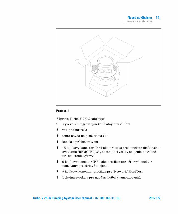
Návod na Obsluhu Príprava na inštaláciu
14
Turbo-V 2K-G Pumping System User Manual / 87-900-968-01 (G) 251/372
Postava 1
Súprava Turbo-V 2K-G zahrŌuje:
1 výveva s integrovaným kontrolným modulom
2 vstupná mriežka
3 tento návod na použitie na CD
4 kabela s príslušenstvom
5 15 kolíkový konektor IP-54 ako protikus pre konektor diaŇkového ovládania "REMOTE I/O" , obsahujúci všetky spojenia potrebné pre spustenie vývevy
6 9 kolíkový konektor IP-54 ako protikus pre sériový konektor používaný pre sériové spojenie
7 9 kolíkový konektor, protikus pre "Network" MoniTorr
8 Úchytná svorka a pre napájací kábel (namontovaná).

14 Návod na Obsluhu Inštalácia
252/372 Turbo-V 2K-G Pumping System User Manual / 87-900-968-01 (G)
Inštalácia
NEBEZPEþÍE!
Kvôli jej váhe, s vývevou manipulujte s pomocou vhodných pomôcok a nástrojov. Použite závesné oÿká zaskrutkované do otvorov v telese vývevy.
POZOR! Neodstrałujte priskrutkovaný ochranný kryt skôr, než pripojíte turbovývevu k systému.
POZOR! Kryty z konektorov odstráłte až po pripevnení turbovývevy k sústave.
Postava 2
Vývevu neinštalujte ani nepoužívajte v prostredí vystavenom vonkajším vplyvom (dážķ, sneh, Ňad), prach, korozívne plyny, ani vo výbušných prostrediach alebo tam, kde existuje vysoké riziko požiaru. Poĵas ĵinnosti zariadenia je potrebné zabezpeĵiř tieto vlastnosti prostredia:
WA
RN
ING
REMOVE THIS PROTECTION AFTER
MECHANICAL INSTALLATION
NO
CHAMBER
YES
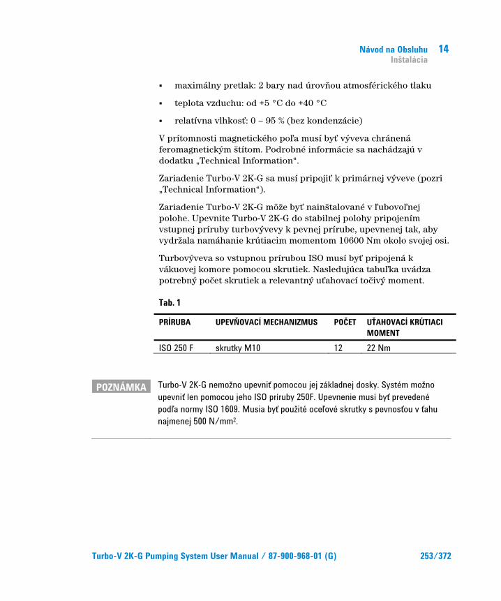
Návod na Obsluhu Inštalácia
14
Turbo-V 2K-G Pumping System User Manual / 87-900-968-01 (G) 253/372
� maximálny pretlak: 2 bary nad úrovŌou atmosférického tlaku
� teplota vzduchu: od +5 °C do +40 °C
� relatívna vlhkosř: 0 – 95 % (bez kondenzácie)
V prítomnosti magnetického poŇa musí byř výveva chránená feromagnetickým štítom. Podrobné informácie sa nachádzajú v dodatku „Technical Information“.
Zariadenie Turbo-V 2K-G sa musí pripojiř k primárnej výveve (pozri „Technical Information“).
Zariadenie Turbo-V 2K-G môže byř nainštalované v ŇubovoŇnej polohe. Upevnite Turbo-V 2K-G do stabilnej polohy pripojením vstupnej príruby turbovývevy k pevnej prírube, upevnenej tak, aby vydržala namáhanie krútiacim momentom 10600 Nm okolo svojej osi.
Turbovýveva so vstupnou prírubou ISO musí byř pripojená k vákuovej komore pomocou skrutiek. Nasledujúca tabuŇka uvádza potrebný poĵet skrutiek a relevantný uřahovací toĵivý moment.
Tab. 1
PRÍRUBA UPEVŁOVACÍ MECHANIZMUS POþET UŘAHOVACÍ KRÚTIACI MOMENT
ISO 250 F skrutky M10 12 22 Nm
POZNÁMKA Turbo-V 2K-G nemožno upevniř pomocou jej základnej dosky. Systém možno upevniř len pomocou jeho ISO príruby 250F. Upevnenie musí byř prevedené podĺa normy ISO 1609. Musia byř použité oceĺové skrutky s pevnosřou v řahu najmenej 500 N/mm2.

14 Návod na Obsluhu Inštalácia
254/372 Turbo-V 2K-G Pumping System User Manual / 87-900-968-01 (G)
POZOR! Zariadenie Turbo-V 2K-G patrí do druhej inštalaÿnej (prepäřovej) kategórie podĺa smernice EN 61010-1. Zariadenie je potrebné pripojiř ku zdroju napájania, ktorý vyhovuje uvedenej kategórii. Zariadenie Turbo-V 2K-G má konektory pre vstup/výstup a konektory sériovej komunikácie, ktoré je potrebné pripojiř k vonkajším okruhom tak, aby nebola dostupná žiadna elektrická súÿasř. Pre získanie úrovne ochrany IP-54 použite dodané protikusy konektorov. Presvedÿite sa, ÿi zariadenie, pripojené k Turbo-V 2K-G má adekvátnu izoláciu aj pre prípad samostatnej chyby podĺa smernice EN 61010-1.
O inštalácia doplnkovej výbavy pozri príruĵku “Technical Information”.

Návod na Obsluhu Použitie
14
Turbo-V 2K-G Pumping System User Manual / 87-900-968-01 (G) 255/372
Použitie Táto ĵasř popisuje základné spôsoby použitia zariadenia. Skôr než zaĵnete systém používař, zapojte všetky elektrické a pneumatické pripojenia. Teplota vstupnej príruby poĵas zahrievania vákuovej komory nesmie prekroĵiř 80 °C.
Poĵas prevádzky vývevy teplota rotora nesmie prekroĵiř 120 °C. PoužívateŇ musí zvoliř správny plynový režim, podŇa aký plyn sa ĵerpá. 1 pre N2 a Ňahké plyny, 0 pre argón (východzie nastavenie). Podrobné informácie sa nachádzajú v dodatku „Technical Information“.
NEBEZPEþÍE!
Nikdy nepoužívajte turbovývevu, ak vstupná príruba nie je pripojená k vákuovej komore, alebo nie je zablendovaná. V priebehu zahrievania sa nikdy nedotýkajte turbovývevy ani žiadneho príslušenstva. Vysoké teploty môžu spôsobiř popáleniny.
POZOR! Dbajte na to, aby výveva poÿas ÿinnosti nebola vystavená nárazom, kmitaniu alebo prudkým pohybom. Mohli by sa poškodiř ložiská. Vývevu preplachujte pomocou vzduchu alebo inertného plynu, zbaveného prachu a ÿastíc. Tlak na preplachovacom vstupe musí byř nižší než 1 bar (pretlakový). Vývevy sú vybavené špeciálnym vstupom na vyÿerpávanie plynov s obsahom ÿastic alebo zneÿišřujúcich látok, agresívních voÿi ložiskám, ktoré umožłujú stabilný tok inertného plynu (dusík a hélium) kvôli ochrane ložísk vývevy (pozri dodatok „Technical Information“).
POZOR! Nikdy nepoužívajte vývevu v pre korozívne plyne alebo výpary, ktoré by mohli poškodiř materiály, použité vo vnútri vývevy.

14 Návod na Obsluhu Použitie
256/372 Turbo-V 2K-G Pumping System User Manual / 87-900-968-01 (G)
NEBEZPEþÍE!
Ak vývevu používate na vyÿerpávanie toxických, horĺavých alebo rádioaktívnych plynov, dodržiavajte prosím požadované postupy pre likvidáciu jednotlivých plynov. Nepoužívajte vývevu v prítomnosti výbušných plynov. Výveva je navrhnuté pre veĺké prietoky dusíka, argónu a ĺahkých plynov. Ak potrebujete ÿerpař plyn řažší ako argón, informujte sa u technickej podpory firmy Agilent.
Použitie zariadenia Turbo-V 2K-G
Ako zariadenie spustiř Pre spustením systému skontrolujte, ĵi je pripojený príslušný I/O konektor. Ak je systém pripojený ku vzdialenému I/O, prerušte signál (pozri odstavec "J1-REMOTE I/O" dodatku k "Technical Information").
Systém naštartujte sledom nasledovných krokov:
1 odpojte (ak je pripojený) I/O konektor
2 zasuŌte napájaciu šnúru
3 vyĵerpajte vákuovú komoru na 0,1 mbar
4 Dajte signál pre spustenie vývevy Turbo-V 2K-G jedným z nasledovných spôsobov.
a pripojením dodaného protikusu I/O konektora
b poslaním vzdialeného signálu spustenia cez I/O konektor (pozri odstavec "J1-REMOTE I/O" dodatku k "Technical Information").
c poslaním vzdialeného signálu spustenia cez rozhranie RS 232/485 (pozri odstavec "Popis komunikácie cez RS232/RS 485" dodatku k "Technical Information").

Návod na Obsluhu Použitie
14
Turbo-V 2K-G Pumping System User Manual / 87-900-968-01 (G) 257/372
NEBEZPEþÍE!
Ak funguje napájanie a je pripojený príslušný východzí 15 kolíkový konektor, zariadenie Turbo-V 2K-G sa spustí automaticky.
POZOR! Kontrolný modul sa dodáva mechanicky aj elektricky pripojený k výveve. Odpojenie kontrolného modulu od vývevy treba zveriř autorizovaným servisným technikom firmy Agilent Vacuum Technologies.
POZNÁMKA Pri prvom spustení vývevy Turbo-V 2K-G kontrolný modul automaticky naštartuje systém zvláštnym postupom, ktorý chráni ložiská systému pred poškodením (SOFT START). Systém sa dosiahne plnú rýchlosř postupne v ÿasovom intervale od 10 minút do jednej hodiny. KeĎ systém dosiahol plnú rýchlosř, režim soft štartu je zablokovaný a Ďalšie spustenia prebiehajú normálnym spôsobom.
POZNÁMKA Pre získanie úrovne ochrany IP-54 použite konektory dodané s vývevou. Použite konektory PN: 969-9957 alebo 969-9958 pre napájaciu šnúru a pripevnite ich ku kontrolnému modulu vhodnými svorkami (pozri nasledujúci obrázok). Túto šnúru so zástrÿkou používajte spolu s vhodne uzemnenou zásuvkou, aby nedošlo k zásahu elektrickým prúdom a aby boli splnené požiadavky noriem ES.
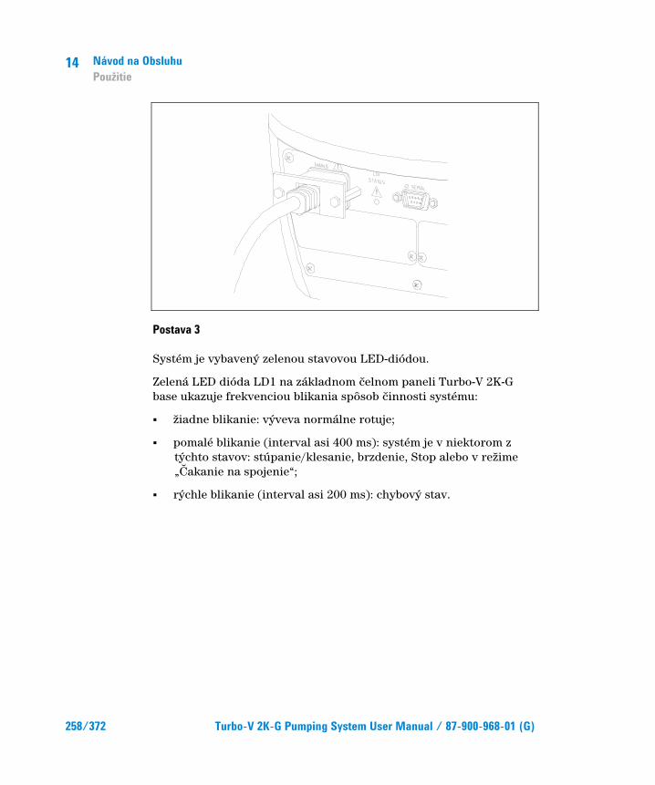
14 Návod na Obsluhu Použitie
258/372 Turbo-V 2K-G Pumping System User Manual / 87-900-968-01 (G)
Postava 3
Systém je vybavený zelenou stavovou LED-diódou.
Zelená LED dióda LD1 na základnom ĵelnom paneli Turbo-V 2K-G base ukazuje frekvenciou blikania spôsob ĵinnosti systému:
� žiadne blikanie: výveva normálne rotuje;
� pomalé blikanie (interval asi 400 ms): systém je v niektorom z týchto stavov: stúpanie/klesanie, brzdenie, Stop alebo v režime „øakanie na spojenie“;
� rýchle blikanie (interval asi 200 ms): chybový stav.
Návod na Obsluhu Použitie
14
Turbo-V 2K-G Pumping System User Manual / 87-900-968-01 (G) 259/372
Ako zariadenie zastaviř Vývevu môžete zastaviř jedným z nasledujúcich spôsobov:
1 odpojením dodaného I/O konektora opaĵného pohlavia
2 poslaním vzdialeného signálu stop cez I/O konektor (pozri odstavec "J1-REMOTE I/O" dodatku k "Technical Information")
3 poslaním vzdialeného signálu stop cez rozhranie RS 232/485 (pozri odstavec "Popis komunikácie cez RS232/RS 485" dodatku k "Technical Information").
Núdzové zastavenie Ak chcete zariadenie Turbo-V 2K-G okamžite vypnúř v stave núdze, musíte vytiahnuř kábel napájania zo zásuvky zdroja napájania. Je však potrebné mař na pamäti, že táto operácia, okrom toho, že úplne vypne napájanie vyradeného ĵerpadla i všetky ostatné funkcie kontrolného zariadenia, ako napr. správu riadeného preplachovania (Purge) a odvzdušŌovania (Vent), zruší i schopnosř sériovej komunikácie, komunikácie prostredníctvom zbernice Profibus alebo prostredníctvom I/Os so systémom, do ktorého bolo ĵerpadlo vstavané.
Okrem toho táto operácia nedokáže zaruĵiř okamžité zastavenie rotora, rýchlosř ktorého klesne v závislosti od stupŌa vákua v systéme.
14 Návod na Obsluhu Údržba
260/372 Turbo-V 2K-G Pumping System User Manual / 87-900-968-01 (G)
Údržba Zariadenie Turbo-V 2K-G nevyžaduje žiadnu údržbu. AkékoŇvek úpravy a opravy systému musí vykonař autorizovaný personál.
NEBEZPEþÍE!
Skôr než zaÿnete ÿokoĺvek robiř v systéme, odpojte ho od zdroja napájania, vyvetrajte vývevu tak, že otvoríte príslušný ventil, poÿkajte, kým sa rotor neprestane otáÿař a kým teplota povrchu vývevy neklesne pod 50 °C.
V prípade poruchy zariadenia vyhŇadajte kontaktné stredisko spoloĵnosti Agilent, kde vám pokazený systém vymenia.
POZNÁMKA Skôr než systém odošlete na opravu alebo výmenu, musíte vyplniř dotazník “Zdravie a bezpeÿnosř”, Dotazník pripojený k návodu na použitie je potrebné vyplniř a odoslař miestnemu predajcovi. Kópiu dotazníka vložte do balíka so systémom a odošlite spolu s ním.
Ak je potrebná likvidácia systému, musí prebehnúř v súlade so špecifickými predpismi danej krajiny.

Návod na Obsluhu Likvidácia
14
Turbo-V 2K-G Pumping System User Manual / 87-900-968-01 (G) 261/372
Likvidácia Význam loga "WEEE" nachádzajúceho sa na štítkoch. Aplikovanie doluozznaĵeného symbolu dodržuje smernicu EÚ s názvom "WEEE". Tento symbol (platný iba pre štáty Európskej Únie) znamená, že výrobok s týmto štítkom NESMIE byř odstránený spolu s bežným domácim alebo priemyselným odpadom, ale sa musí odstrániř ako delený odpad. Vyzývame preto koneĵného užívateŇa, aby sa skontaktoval s dodávateŇom prístroja, ĵi už je to výrobca alebo predajca za úĵelom jeho likvidácie podŇa zmluvných podmienok predaja.
14 Návod na Obsluhu Likvidácia
262/372 Turbo-V 2K-G Pumping System User Manual / 87-900-968-01 (G)

Turbo-V 2K-G Pumping System User Manual
263/372
15 Priroÿnik za Navodila Varnostna navodila za Turbomolekularne ÿrpalke 264 Splošne informacije 265 Shranjevanje 267 Priprava za montažo 268 Montaža 270 Uporaba 273 Uporaba Turbo-V 2K-G 274 Zagon sistema 274 Zaustavljanje sistema 277 Zaustavitev v sili 277 Vzdrževanje 278 Odlaganje opadkov 279 Prevod navodil v izvirniku

15 Priroÿnik za Navodila Varnostna navodila za Turbomolekularne ÿrpalke
264/372 Turbo-V 2K-G Pumping System User Manual / 87-900-968-01 (G)
Varnostna navodila za Turbomolekularne ÿrpalke Turbomolekularne ĵrpalke, opisane v naslednjih navodilih vsebujejo veliko koliĵino kinetiĵne energije zaradi visoke hitrosti v povezavi s specifiĵnimi masami rotorjev.
V primeru nepravilnega delovanje sistema, na primer pri dotiku rotorja/statorja ali poškodbe rotorja se lahko sprosti rotacijska energija.
SVARILO!
Da bi se izognili poškodbam opreme in prepreÿili poškodbe osebja morate natanÿno slediti navodilom za namešÿanje iz tega priroÿnika!
Priroÿnik za Navodila Splošne informacije
15
Turbo-V 2K-G Pumping System User Manual / 87-900-968-01 (G) 265/372
Splošne informacije Oprema je namenjena za profesionalno uporabo. Pred uporabo mora uporabnik prebrati navodila za uporabo in vse dodatne informacije, ki mu jih je posredoval Agilent. Agilent ni odgovoren za dogodke, ki bi nastali zaradi neupoštevanja teh navodil, nepravilne uporabe in nepooblašĵenega poseganja v opremo ali kakršnega koli dejanja, ki niso v skladu s standardi.
Turbo-V 2K-G je integriran sistem s turbomolekularno ĵrpalko za visoko in ultra visoko vakuumsko uporabo s primernim krmilnikom. Sistem lahko ĵrpa vse tipe plinova ali plinskih zmesi. Ni primeren za ĵrpanje tekoĵine ali trdnih delcev. ørpanje se izvaja preko hitre turbine (maks. 33000 rpm), ki jo vodi visoko uĵinkovit 3-fazni elektriĵni motor. Turbo-V 2K-G ne vsebuje onesnaževalnih agentov in je primeren za »ĵisto« vakuumiranje.
Opremljen je z auksiliarnimi prikljuĵki, ki jih lahko krmilite iz oddaljene lokacije z gostiteljskim raĵunalnikom, povezanim preko serijske povezave (RS232 ali RS485).
Naslednji odstavki vsebujejo informacije, ki so potrebne za varnost tistega, ki uporablja to opremo. Podrobne informacije lahko najdete v prilogi »Technical Information«.
15 Priroÿnik za Navodila Splošne informacije
266/372 Turbo-V 2K-G Pumping System User Manual / 87-900-968-01 (G)
Navodila so napisana po naslednjem standardnem protokolu:
SVARILO!
Svarilo so za to, da pritegnejo pozornost uporabnika na doloÿene postopke pri katerih lahko pride do resnih poškodb, ÿe se jih ne drži.
POZOR! Sporoÿila so prikazana pred postopki pri katerih lahko pride do poškodbe opreme.
OPOMBA Opombe vsebujejo vse najbolj pomembne informacije iz besedila.

Priroÿnik za Navodila Shranjevanje
15
Turbo-V 2K-G Pumping System User Manual / 87-900-968-01 (G) 267/372
Shranjevanje Da bi zagotovili maksimalni uĵinek in zanesljivost ĵrpalk Agilent Turbomolecular se morate držati naslednjih vodil:
� Pri pošiljanju, premikanju in shranjevanju ĵrpalk ne smete preseĵi naslednjih specifikacij:
� temperaturno obmoĵje: -20 °C do 70 °C
� obmoĵje relativne vlažnosti: 0 do 95 % (brez kondenza)
� Turbomolekularne ĵrpalke morate pred prvo uporabo zmerja zagnati mehko.
� Življenjska doba turbomolekularne ĵrpalke je 10 mesecev od datum pošiljanja.
POZOR! þe zaradi kakršnega koli razloga presežete življenjsko dobo, je treba ÿrpalko vrniti v tovarno. Za dodatne informacije kontaktirajte lokalnega predstavnika prodaje in storitev za Agilent Vacuum.
15 Priroÿnik za Navodila Priprava za montažo
268/372 Turbo-V 2K-G Pumping System User Manual / 87-900-968-01 (G)
Priprava za montažo Naprava Turbo-V 2K-G je dobavljena v posebni zašĵitni embalaži. øe je embalaža poškodovana, kontaktirajte lokalno prodajno pisarno.
Odstranite zašĵito spajal samo potem, ko je turboĵrpalka že prikljuĵena na sistem.
Pri odpiranju sistema pazite, da vam ne pade iz rok oz. ga ne stresajte. Zaradi teže (35 kg) uporabite tri vijake, ki jih postavite 120° na ohišje ĵrpalke, da jo izvleĵete iz embalaže.
Embalažo zavrzite v skladu s pravili. Material je možno v celoti reciklirati in je v skladu z ECC direktivo 85/399.
POZOR! Komponent, ki bodo izpostavljene vakuumu se ne dotikajte z golimi rokami, saj boste tako prepreÿili probleme pušÿanja. Zmeraj uporabite rokavice ali drugo primerno zašÿito.
OPOMBA Normalna izpostavljenost na okolje ne more poškodovati Turbo-V 2K-G naprave. Vendarle je priporoÿljivo, da je naprava zaprta, dokler je ne namestite v sistem. S tem boste onemogoÿili onesnaženje sistema.
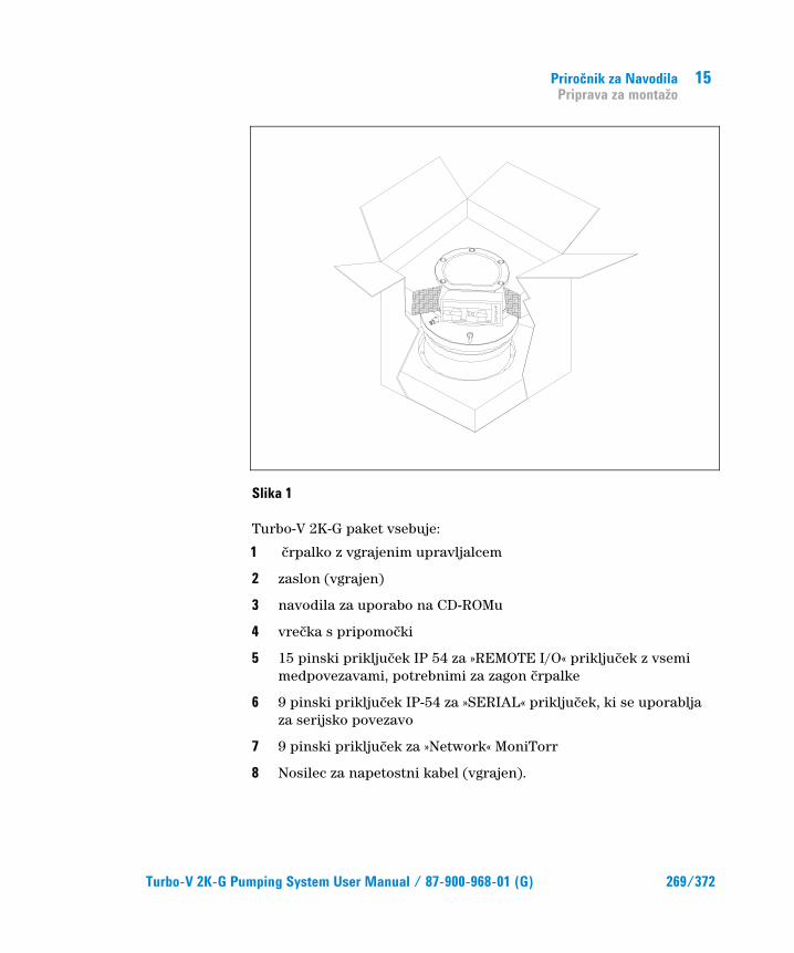
Priroÿnik za Navodila Priprava za montažo
15
Turbo-V 2K-G Pumping System User Manual / 87-900-968-01 (G) 269/372
Slika 1
Turbo-V 2K-G paket vsebuje:
1 ĵrpalko z vgrajenim upravljalcem
2 zaslon (vgrajen)
3 navodila za uporabo na CD-ROMu
4 vreĵka s pripomoĵki
5 15 pinski prikljuĵek IP 54 za »REMOTE I/O« prikljuĵek z vsemi medpovezavami, potrebnimi za zagon ĵrpalke
6 9 pinski prikljuĵek IP-54 za »SERIAL« prikljuĵek, ki se uporablja za serijsko povezavo
7 9 pinski prikljuĵek za »Network« MoniTorr
8 Nosilec za napetostni kabel (vgrajen).

15 Priroÿnik za Navodila Montaža
270/372 Turbo-V 2K-G Pumping System User Manual / 87-900-968-01 (G)
Montaža
SVARILO!
Zaradi teže je treba za rokovanje s ÿrpalko uporabiti primerne naprave za premikanje. Uporabite vijake, ki se nahajajo v luknjah na telesu ÿrpalke.
POZOR! Lepljiv in zašÿitni pokrov ne odstranjujte dokler ne povežete turbo ÿrpalko na sistem.
POZOR! Odstranite zašÿito spajal samo potem, ko je turboÿrpalka že prikljuÿena na sistem.
Slika 2
Napravo namešĵajte samo odznotraj in v nobenem primeru je ne namešĵajte v okolju, ki je izpostavljeno na atmosferske agente (dež, sneg, led), prah, agresivni plini ali v okoljih kjer obstaja nevarnost požara. Tekom delovanja je treba spošotvati naslednje pogoje:
WA
RN
ING
REMOVE THIS PROTECTION AFTER
MECHANICAL INSTALLATION
NO
CHAMBER
YES
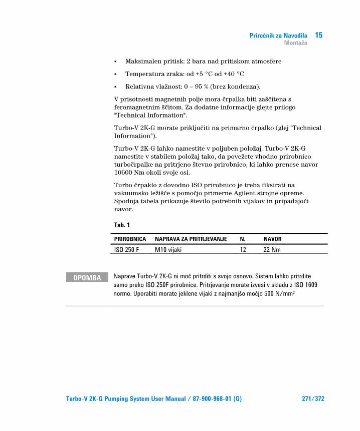
Priroÿnik za Navodila Montaža
15
Turbo-V 2K-G Pumping System User Manual / 87-900-968-01 (G) 271/372
� Maksimalen pritisk: 2 bara nad pritiskom atmosfere
� Temperatura zraka: od +5 °C od +40 °C
� Relativna vlažnost: 0 – 95 % (brez kondenza).
V prisotnosti magnetnih polje mora ĵrpalka biti zašĵitena s feromagnetnim šĵitom. Za dodatne informacije glejte prilogo "Technical Information".
Turbo-V 2K-G morate prikljuĵiti na primarno ĵrpalko (glej "Technical Information").
Turbo-V 2K-G lahko namestite v poljuben položaj. Turbo-V 2K-G namestite v stabilem položaj tako, da povežete vhodno prirobnico turboĵrpalke na pritrjeno števno prirobnico, ki lahko prenese navor 10600 Nm okoli svoje osi.
Turbo ĵrpaklo z dovodno ISO prirobnico je treba fiksirati na vakuumsko ležišĵe s pomoĵjo primerne Agilent strojne opreme. Spodnja tabela prikazuje število potrebnih vijakov in pripadajoĵi navor.
Tab. 1
PRIROBNICA NAPRAVA ZA PRITRJEVANJE N. NAVOR
ISO 250 F M10 vijaki 12 22 Nm
OPOMBA Naprave Turbo-V 2K-G ni moÿ pritrditi s svojo osnovo. Sistem lahko pritrdite samo preko ISO 250F prirobnice. Pritrjevanje morate izvesi v skladu z ISO 1609 normo. Uporabiti morate jeklene vijaki z najmanjšo moÿjo 500 N/mm2

15 Priroÿnik za Navodila Montaža
272/372 Turbo-V 2K-G Pumping System User Manual / 87-900-968-01 (G)
POZOR! Po direktivi EN 61010-1 spada Turbo-V 2K-G v skupino za drugo namešÿanje (ali prekovoltažo). Napravo priljuÿite na napetost, ki je v vskladu z zgornjo kategorijo. Naprava Turbo-V 2K-G ima vhodne/izhodne in serijske prikljuÿke, ki jih je treba povezati na zunanja vezja tako, da noben elektriÿni del ni dosegljiv. Za vzdrževanje IP-54 zašÿitnega nivoja uporabite priložene prikljuÿke. Prepriÿajte se, da je izolacija naprave, prikljuÿene na Turbo-V 2K-G, primerna tudi v primerno ene napake, kar je opisano v direktivi EN 61010-1.
Za namestitev opcijski dodatkov, glej »Technical Information«.
Priroÿnik za Navodila Uporaba
15
Turbo-V 2K-G Pumping System User Manual / 87-900-968-01 (G) 273/372
Uporaba Ta odstavek opisuje osnovne postopke za uporabo.
Pred uporabo sistema povežite vse elektriĵne in pnevmatske povezave.
Pri segrevanju vakuumskega ležišĵa temperatura dovodne prirobnice ne sme preseĵi 80 °C.
Med delovanjem ĵrpalke rotor ne sme preseĵi temperature 120 °C. Uporabnik mora nastaviti pravilen naĵin plina v skladu s plinom, ki se ĵrpa: 1 za N2 in lažje pline, 0 za Argon (privzeto). Za dodatne informacije glejte prilogo "Technical Information".
SVARILO!
Turbo ÿrpalke ne uporabljajte, ÿe dovodna prirobnica ni prikljuÿena na vakuumsko ležišÿe. Tekom segrevanja se turbo ÿrpalke ali njenih delov ne dotikajte. Visoka temperatura lahko povzroÿi opekline.
POZOR! Izogibajte se udarcem, oscilacijam ali nenadnim premikom ÿrpalke tekom delovanja. Nosilci se lahko poškodujejo. Za prezraÿevanje ÿrpalke uporabite zrak ali inertni plin brez prahu ali delcev. Pritisk na oddušniku mora biti manjši od 1 bara (nad pritiskom atmosfere). Za ÿrpanje plinov, ki vsebujejo trdne delce ali agresivnih onesnaževalnikov za ležaje, so te ÿrpalke opremljene s prikljuÿkom, ki omogoÿa stalen pretok inertnih plinov (Dušik ali Helij) za zašÿito nosilcev (glej prilogo “Technical Information”).
POZOR! þrpalke nikoli ne uporabljajte v prisotnosti razjednih plinov ali hlapov, ki bi lahko poškodovali inertne materiale ÿrpalke.
15 Priroÿnik za Navodila Uporaba
274/372 Turbo-V 2K-G Pumping System User Manual / 87-900-968-01 (G)
SVARILO!
Pri ÿrpanju strupenih, vnetljivih ali radioaktivnih plinov, sledite zahtevanim navodilom za odstranjevanje vsakega plina. þrpalke ne uporabljajte v prisotnosti eksplozivnih plinov. þrpalka je narejena za hitro ÿrpanje N2, Ar in lažjih plinov. þe želite ÿrpati pline, ki so težji od Ar, prosimo, da kontaktirate Agilent tehniÿno podporo za veÿ informacij.
Uporaba Turbo-V 2K-G
Zagon sistema Preden sistem zaženete se prepriĵajte, da je I/O prikljuĵek izkljuĵen. øe je sistem povezan na oddaljen I/O, se prepriĵajte, da je na voljo stop signal (glej odstavek "J1-REMOTE I/O" v prilogi "Technical Information").
Za zagon sistema sledite naslednjim korakom:
1 izkljuĵite (ĵe je na voljo) sistemski I/O prikljuĵek
2 prikljuĵite napetost
3 izĵrpajte vakuumsko posodo do 0.1 mbar
4 oddajte signal za zaĵetek z enim od naslednjih naĵinov:
a Prikljuĵite priložen I/O prikljuĵek
b Oddajte oddaljeni signal za zagon preko I/O prikljuĵka (glej odstavek "J1-REMOTE I/O" v prilogi "Technical Information").
c Oddajte oddaljeni signal za zagon preko RS 232/485 serijskega vmesnika (glej odstavek "RS232/RS 485 Opis komunikacij" v prilogi "Technical Information").

Priroÿnik za Navodila Uporaba
15
Turbo-V 2K-G Pumping System User Manual / 87-900-968-01 (G) 275/372
SVARILO!
Ko je dovedena napetost in je vstavljen tovarniško privzeti 15 pin se Turbo-V 2K-G samodejno zažene.
POZOR! Upravljalec je mehansko in elektronsko povezan na ÿrpalko. Odstranjevanje upravljalca iz ÿrpalke mora izvesti samo pooblašÿeno osebje Agilent Vacuum Technologies.
OPOMBA Ko prviÿ zaženete Turbo-V 2K-G, kontrolna enota samodejno zažene sistem s posedbno proceduro, ki zavaruje teÿaje proti poškodbam (SOFT START) Sistem se po korakih zažene do polne hitrosti v ÿasu od 10 minut do 1 ure. Ko sistem doseže polno hitrost se mehki zagon onemogoÿi in naslednji zagoni so normalni.
OPOMBA Za vzdrževanje IP-54 zašÿitnega nivoja morate uporabljati samo prikljuÿke, ki so bili zraven ÿrpalke. Uporabite prikljuÿke PN: 969-9957 ali 969-9958 za napetostni kabel, ki ga pritrdite na upravljalec s posebnim nosilcem (glej naslednjo skico). Uporabljajte ta kabel in vtikaÿ skupaj s primerno ozemljeno vtiÿnico, tako, da vas tok ne strese in da zadovoljite EU predpisom.
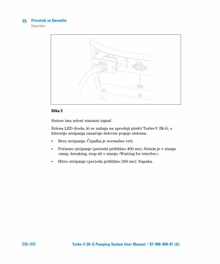
15 Priroÿnik za Navodila Uporaba
276/372 Turbo-V 2K-G Pumping System User Manual / 87-900-968-01 (G)
Slika 3
Sistem ima zeleni statusni signal
Zelena LED dioda, ki se nahaja na sprednji plošĵi Turbo-V 2K-G, s hitrostjo utripanja oznaĵuje delovne pogoje sistema:
� Brez utripanja: ørpalka je normalno vrti;
� Poĵasno utripanje (perioda približno 400 ms): Sistem je v stanju ramp, breaking, stop ali v stanju »Waiting for interloc«;
� Hitro utripanje (perioda približno 200 ms): Napaka.
Priroÿnik za Navodila Uporaba
15
Turbo-V 2K-G Pumping System User Manual / 87-900-968-01 (G) 277/372
Zaustavljanje sistema Za zaustavljanje sistema lahko uporabite eno od naslednjih metod:
1 prikljuĵite priložen I/O prikljuĵek
2 oddajte oddaljeni signal za zagon preko I/O prikljuĵka (glej odstavek "J1-REMOTE I/O" v prilogi "Technical Information")
3 Oddajte oddaljeni signal za zagon preko RS 232/485 serijskega vmesnika (glej odstavek "RS232/RS 485 Opis komunikacij" v prilogi "Technical Information").
Zaustavitev v sili Za zaustavitev naprave Turbo-V 2K-G v sili morate odstraniti napetost. Treba je vsekakor upoštevati dejstvo, da ta operacija ne le popolnoma onemogoĵi napajanje ĵrpalke, temveĵ onemogoĵi tudi vse druge funkcije krmilnika, kot so na primer upravljanje nadzorovanega øišĵenja in Izpusta in sposobnost sporoĵanja s sistemom, v katerem je ĵrpalka vgrajena s serijskim ali profibus-om I/Os.
Ta operacija tudi ne more zagotoviti hitro zaustavitev rotorja, ĵigar hitrost vrtenja bo pojenjala skladno s stopnjo vakuuma v sistemu.
15 Priroÿnik za Navodila Vzdrževanje
278/372 Turbo-V 2K-G Pumping System User Manual / 87-900-968-01 (G)
Vzdrževanje Turbo-V 2K-G ne potrebuje vzdrževanja. Kakršno koli delo na sistemu mora opraviti avtorizirano osebje.
SVARILO!
Pred zaÿetkom dela na sistemu, ga izkljuÿite iz napetosti, preÿistite ÿrpalko tako, da odprete primerno odprtino, poÿakajte, da se rotor ustavi an poÿakajte, da površinska temperatura ÿrpalke pade pod 50 °C.
V primeru okvare, kontaktirajte lokalni Agilent servisni center, ki vam lahko zamenja pokvarjen sistem z novim.
OPOMBA Preden odnesete sistem na popravilo ali zamenjavo z drugo enoto, morate izpolniti »Health and Safety« obrazec, ki je pri-ložen navodilom in ga poslate lokalni prodajni pisarni. Pred pošiljanjem morate kopijo obrazca vstaviti v embalažo sistema.
Sistem je treba uniĵiti v skladu z doloĵenimi nacionalnimi standardi.

Priroÿnik za Navodila Odlaganje opadkov
15
Turbo-V 2K-G Pumping System User Manual / 87-900-968-01 (G) 279/372
Odlaganje opadkov Pomen znamke "WEEE" na etiketah. Spodaj navedeni simbol je v skladu z direktivo ES znano pod imenom "WEEE". Ta simbol (ki velja samo v državah Evropske Skupnosti) pomeni, da izdelek NE SMETE ODSTRANITI skupaj z ostalimi komunalnimi ali pa industrijskimi odpadki, temveĵ morate poskrbeti za njihovo primerno loĵevanje. Zato pozivamo uporabnike, da se ali pri prodajalnem centru ali pa pri prodajalcu seznani o postopku loĵevanja in odstranitve odpadkov, šele nato, ko se je seznanil s pogoji in z merili kupopordajne pogodbe.

15 Priroÿnik za Navodila Odlaganje opadkov
280/372 Turbo-V 2K-G Pumping System User Manual / 87-900-968-01 (G)

Turbo-V 2K-G Pumping System User Manual
281/372
16 Instructions for Use Safety Guideline for Turbomolecular Pumps 282 General Information 283 Storage 285 Preparation for Installation 286 Installation 288 Use 291 Use of Turbo-V 2K-G 292 How to Start the System Up 292 How to Stop the System 295 Emergency Stop 295 Maintenance 296 Disposal 297 Original Instructions

16 Instructions for Use Safety Guideline for Turbomolecular Pumps
282/372 Turbo-V 2K-G Pumping System User Manual / 87-900-968-01 (G)
Safety Guideline for Turbomolecular Pumps Turbomolecular pumps as described in the following operating manual contain a large amount of kinetic energy due to the high rotational speed in combination with the specific mass of their rotors.
In case of a malfunction of the system for example rotor/stator contact or even a rotor crash the rotational energy may be released.
WARNING!
To avoid damage to equipment and to prevent injuries to operating personnel the installation instructions as given in this manual should be strictly followed!

Instructions for Use General Information
16
Turbo-V 2K-G Pumping System User Manual / 87-900-968-01 (G) 283/372
General Information This equipment is destined for use by professionals. The user should read this instruction manual and any other additional information supplied by Agilent before operating the equipment. Agilent will not be held responsible for any events occurring due to non-compliance, even partial, with these instructions, improper use by untrained persons, non-authorized interference with the equipment or any action contrary to that provided for by specific national standards.
The Turbo-V 2K-G is an integrated system with a turbo-molecular pump for high and ultra-high vacuum applica-tions with its relevant controller. The system can pump many types of gases or gas compound. It is not suitable for pumping liquids or solid particles. The pumping action is obtained through a high speed turbine (max. 33000 rpm) driven by a high-performance 3-phase electric motor. The Turbo-V 2K-G is free of contaminating agents and, therefore, is suitable for applications requiring a "clean" vacuum.
It is equipped with auxiliary connectors to be controlled from a remote site by means of an host computer connected through a serial line (RS232 or RS485).
The following paragraphs contain all the information necessary to guarantee the safety of the operator when using the equipment. Detailed information is supplied in the appendix "Technical Information".

16 Instructions for Use General Information
284/372 Turbo-V 2K-G Pumping System User Manual / 87-900-968-01 (G)
This manual uses the following standard protocol:
WARNING!
The warning messages are for attracting the attention of the operator to a particular procedure or practice which, if not followed correctly, could lead to serious injury.
CAUTION! The caution messages are displayed before procedures which, if not followed, could cause damage to the equipment.
NOTE The notes contain important information taken from the text.

Instructions for Use Storage
16
Turbo-V 2K-G Pumping System User Manual / 87-900-968-01 (G) 285/372
Storage In order to guarantee the maximum level of performance and reliability of Agilent Turbomolecular pumps, the following guidelines must be followed:
� when shipping, moving and storing pumps, the following environmental specifications should not be exceeded:
� temperature range: -20 °C to 70 °C
� relative humidity range: 0 to 95 % (non condensing)
� the turbomolecular pumps must be always soft-started when received and operated for the first time by the customer
� the shelf life of a turbomolecular pump is 10 months from the shipping date.
CAUTION! If for any reason the shelf life time is exceeded, the pump has to be returned to the factory. Please contact the local Agilent Vacuum Sales and Service representative for informations.
16 Instructions for Use Preparation for Installation
286/372 Turbo-V 2K-G Pumping System User Manual / 87-900-968-01 (G)
Preparation for Installation The Turbo-V 2K-G is supplied in a special protective pack-ing. If this shows signs of damage which may have occurred during transport, contact your local sales office.
When unpacking the system, be sure not to drop it and avoid any kind of sudden impact or shock vibration to it.
Remove connector protections only after fixing the turbopump to the system.
Cause its weight (35 kg), use the three eyebolts screwed at 120° on the pump body to extract the pump from the package.
Do not dispose of the packing materials in an unauthorized manner. The material is 100% recyclable and complies with EEC Directive 85/399.
CAUTION! In order to prevent outgassing problems, do not use bare hands to handle components which will be exposed to vacuum. Always use gloves or other appropriate protec-tion.
NOTE Normal exposure to the environment cannot damage the Tur-bo-V 2K-G. Nevertheless, it is advisable to keep it closed and sealed until it is installed in the system. This will prevent the system from contamination.

Instructions for Use Preparation for Installation
16
Turbo-V 2K-G Pumping System User Manual / 87-900-968-01 (G) 287/372
Figure 1
The Turbo-V 2K-G package includes:
1 pump with integrated controller
2 inlet screen (mounted)
3 this instruction manual on CD-ROM
4 accessories bag:
5 15 pin mating connector IP 54 for "REMOTE I/O" connector with all the interconnections necessary to start the pump.
6 9 pin mating connector IP-54 for "SERIAL" connector to be used for serial connection
7 9 pin mating connector for "Network" MoniTorr
8 Retaining bracket to retain the power cable (mounted)

16 Instructions for Use Installation
288/372 Turbo-V 2K-G Pumping System User Manual / 87-900-968-01 (G)
Installation
WARNING!
Cause its weight, the pump must be handled by means of suitable moving and handling tools. Use the suitable handling kit eyebolts screwed into the holes of the pump body.
CAUTION! Do not remove the bolted cap before connecting the tur-bopump to the system.
CAUTION! Remove connector protections only after fixing the turbopump to the system.
Figure 2
Do not install or use the pump in an environment exposed to atmospheric agents (rain, snow, ice), dust, aggressive gases, or in explosive environments or those with a high fire risk. During operation, the following environmental conditions must be respected:
� maximum pressure: 2 bar above atmospheric pressure
WA
RN
ING
REMOVE THIS PROTECTION AFTER
MECHANICAL INSTALLATION
NO
CHAMBER
YES
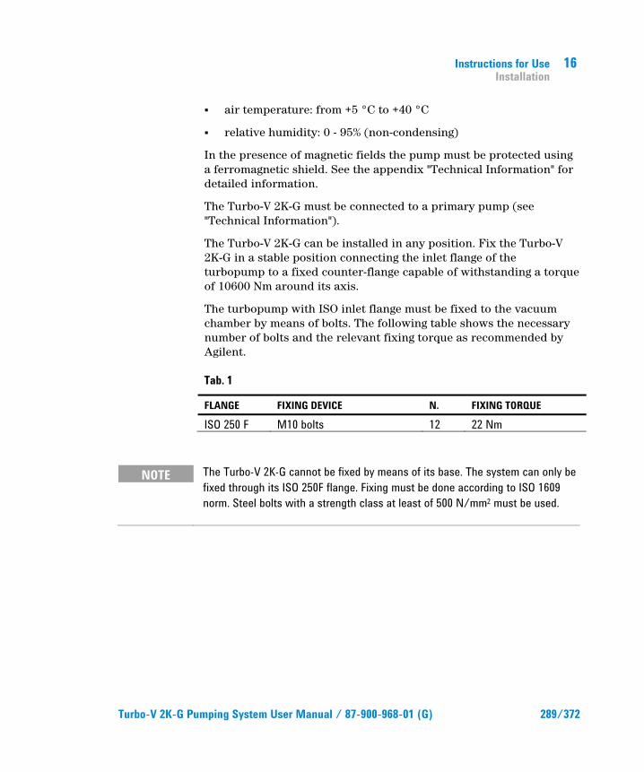
Instructions for Use Installation
16
Turbo-V 2K-G Pumping System User Manual / 87-900-968-01 (G) 289/372
� air temperature: from +5 °C to +40 °C
� relative humidity: 0 - 95% (non-condensing)
In the presence of magnetic fields the pump must be protected using a ferromagnetic shield. See the appendix "Technical Information" for detailed information.
The Turbo-V 2K-G must be connected to a primary pump (see "Technical Information").
The Turbo-V 2K-G can be installed in any position. Fix the Turbo-V 2K-G in a stable position connecting the inlet flange of the turbopump to a fixed counter-flange capable of withstanding a torque of 10600 Nm around its axis.
The turbopump with ISO inlet flange must be fixed to the vacuum chamber by means of bolts. The following table shows the necessary number of bolts and the relevant fixing torque as recommended by Agilent.
Tab. 1
FLANGE FIXING DEVICE N. FIXING TORQUE
ISO 250 F M10 bolts 12 22 Nm
NOTE The Turbo-V 2K-G cannot be fixed by means of its base. The system can only be fixed through its ISO 250F flange. Fixing must be done according to ISO 1609 norm. Steel bolts with a strength class at least of 500 N/mm2 must be used.
16 Instructions for Use Installation
290/372 Turbo-V 2K-G Pumping System User Manual / 87-900-968-01 (G)
CAUTION! The Turbo-V 2K-G belongs to the second installation (or overvoltage) category as per directive EN 61010-1. Connect the device to a mains line that satisfy the above category. The Turbo-V 2K-G has Input/Output and serial communica-tion connectors that must be connected to external circuits in such a way that no electrical part is accessible. Use the provided mating connectors in order to maintain the IP-54 protection level. Be sure that the insulation of the device connected to the Turbo-V 2K-G is adequate even in the case of single fault as per directive EN 61010-1.
For installation of optional accessories, see "Technical Information".

Instructions for Use Use
16
Turbo-V 2K-G Pumping System User Manual / 87-900-968-01 (G) 291/372
Use This paragraph details the fundamental operating procedures.
Make all electrical an pneumatic connections before the use of the system.
While heating the vacuum chamber, the temperature of the inlet flange must not exceed 80 °C.
While operating the pump the rotor temperature must never exceed 120 °C. The user must be sure to set the correct gas mode, according to the pumped gas: 1 for N2 and lighter gases, 0 for Argon (default). See the annex "Technical Information" for details.
WARNING!
Never use the turbopump when the inlet flange is not connected to the vacuum chamber or is not blanked. Do not touch the turbopump or any of its accessories during the heating process. The high temperatures may cause burns.
CAUTION! Avoid impacts, oscillations or harsh movements of the pump when in operation. The bearings may become damaged. Use air or inert gas free from dust or particles for venting the pump. The pressure at the vent port must be less than 1 bar (above atmospheric pressure). For pumping gases containing particulate or aggressive pollutants for the bearings, these pumps are fitted with a special port to allow a steady flow of inert gas (like N2, He) for pump bearing protection (see the appendix "Technical Information").
CAUTION! Never use the pump with corrosive gases or vapor to avoid damage to the internal materials of the pump.
16 Instructions for Use Use
292/372 Turbo-V 2K-G Pumping System User Manual / 87-900-968-01 (G)
WARNING!
When employing the pump for pumping toxic, flammable, or radioactive gases, please follow the required procedures for each gas disposal. Do not use the pump in presence of explosive gases. The pump is designed to pump high throughput of N2, Ar and lighter gas. Should you need to pump gases heavier than Ar, please contact Agilent technical support for information.
Use of Turbo-V 2K-G
How to Start the System Up Before starting the system, please check that the mating I/O connector is unplugged. If the system is connected to a remote I/O, make sure the stop signal (see para. "J1-REMOTE I/O" of annex "Technical Information") is given.
To start the system please follow the following steps:
1 unplug (if present) the system mating I/O connector
2 plug on the mains
3 pump the vacuum chamber down to 0.1 mbar
4 give the Turbo-V 2K-G a start signal by one of the following methods:
a connecting the provided mating I/O connector
b giving a remote start signal through the I/O connector (see para. "J1-REMOTE I/O" of annex "Technical Information")
c giving a remote start signal via the serial RS 232/485 interface (see para. "RS232/RS 485 Communication Description" of annex "Technical Information").

Instructions for Use Use
16
Turbo-V 2K-G Pumping System User Manual / 87-900-968-01 (G) 293/372
WARNING!
When power is supplied and factory default 15 pin mating connector is inserted, the Turbo-V 2K-G will start automatically.
CAUTION! The controller is furnished already mechanically and electrically connected to the pump. Detaching of the controller from the pump must be carried out by authorized Agilent Vacuum Technologies personnel only.
NOTE When you run the Turbo-V 2K-G for the very first time, the control unit automatically starts the system with a special procedure which protects the bearings from possible damages (SOFT START). The system is launched step by step at full speed in a time variable from 10 mins up to 1 hour. After the system has reached the full speed, the soft start procedure is disabled and following starts are performed in the normal way.
NOTE In order to maintain the IP-54 protection level you must use only the connectors provided with the pump. Use connectors PN: 969-9957 or 969-9958 for the power cable and fix it to the controller by means of the suitable retaining bracket (see the following figure). Use this power cord and plug in conjunction with a properly grounded power socket to avoid electrical shock and to satisfy CE requirements.

16 Instructions for Use Use
294/372 Turbo-V 2K-G Pumping System User Manual / 87-900-968-01 (G)
Figure 3
The system is provided with a green status led signal.
The green LED located on the Turbo-V 2K-G base front panel indicates with its flashing frequency the system operating conditions:
� with no flashing: the pump is normally rotating;
� slowly flashing (period of about 400 ms): the system is in ramp, or in braking, or in Stop, or in “Waiting for interlock” status;
� fast flashing (period of about 200 ms): error condition.

Instructions for Use Use
16
Turbo-V 2K-G Pumping System User Manual / 87-900-968-01 (G) 295/372
How to Stop the System To stop the pump you can use one of the following methods:
1 unplugging the provided mating I/O connector
2 giving a remote stop signal through the I/O connector (see para. "J1-REMOTE I/O" of annex "Technical Information")
3 giving a remote stop signal via the serial RS 232/485 interface (see para. "RS232/RS 485 Communication Description" of annex "Technical Information").
Emergency Stop To immediately stop the Turbo-V 2K-G in an emergency condition it is necessary to remove the mains. It must be however noted that this operation, in addition to cutting off the pump power, also cuts off all other controller functions, such as Purge and Controlled Vent management and the capability of communicating with the system in which the pump is integrated via I/Os, Serial or Profibus.
Furthermore, this operation may not ensure the immediate stopping of the rotor. Rotation speed of the rotor will decrease according to the degree of vacuum present in the system.

16 Instructions for Use Maintenance
296/372 Turbo-V 2K-G Pumping System User Manual / 87-900-968-01 (G)
Maintenance The Turbo-V 2K-G does not require any maintenance. Any work performed on the system must be carried out by authorized personnel.
WARNING!
Before carrying out any work on the system, disconnect it from the mains, vent the pump by opening the appropriate valve, wait until the rotor has stopped turning and wait until the surface temperature of the pump falls below 50 °C.
In the case of breakdown, contact your local Agilent service center who can supply a reconditioned system to replace that broken down.
NOTE Before returning the system to the constructor for repairs, or replacement with a reconditioned unit, the "Health and Safety" sheet attached to this instruction manual must be filled-in and sent to the local sales office. A copy of the sheet must be in-serted in the system package before shipping.
If a system is to be scrapped, it must be disposed of in accordance with the specific national standards.
Instructions for Use Disposal
16
Turbo-V 2K-G Pumping System User Manual / 87-900-968-01 (G) 297/372
Disposal Meaning of the "WEEE" logo found in labels
The following symbol is applied in accordance with the EC WEEE (Waste Electrical and Electronic Equipment) Directive. This symbol (valid only in countries of the European Community) indicates that the product it applies to must NOT be disposed of together with ordinary domestic or industrial waste but must be sent to a differentiated waste collection system. The end user is therefore invited to contact the supplier of the device, whether the Parent Company or a retailer, to initiate the collection and disposal process after checking the contractual terms and conditions of sale.

16 Instructions for Use Disposal
298/372 Turbo-V 2K-G Pumping System User Manual / 87-900-968-01 (G)

Turbo-V 2K-G Pumping System User Manual
299/372
17 Technical Information
Description of the Turbo-V 2K-G 301 Pump Description 302 Controller Description 305 Technical Specification 306 Turbo-V 2K-G Outline 309 Interconnections 310 J1 – Remote I/O 310 J2 – Serial 317 Serial Cable Installation 319 RS 232/RS 485 Communication Description 319 Window Meanings 325 MoniTorr 330 Powering on the MoniTorr 330 Operation 331 Maintenance 331 MoniTorr Installation on the Network
and on the Main PC 331 Original Instructions

17 Technical Information
300/372 Turbo-V 2K-G Pumping System User Manual / 87-900-968-01 (G)
MoniTorr Connectivity Kit Installation Procedure 332 Interconnections 335 Network Connector (RS 485) 335 Transmission Channel Characteristics 335 Installing the File Download Software 336 Operating Procedure 338 Download Software 339 Functionality 340 Modifying the Parameters 341 Archive Saving Method Procedure 342 Profibus Option 343 General 343 Mechanical 343 Installation 344 Configuration 344 Indicators 345 Software Operation and State Machine 346 Message Mapping 348 Profibus Message Mapping 349 Diagnostic Management 355 Diagnostic Buffer 356 Inlet Screen Installation 359 Water Cooling Connection 361 Pump Purging and Venting 362 Purge and Vent Installation 362 Pump Used With Corrosive Gases 362 High Vacuum Flange Connection 364 Fore-Vacuum Pump Connection 365 Pump Used in Presence of Magnetic Fields 365 Orderable Parts 366

Technical Information Description of the Turbo-V 2K-G
17
Turbo-V 2K-G Pumping System User Manual / 87-900-968-01 (G) 301/372
Description of the Turbo-V 2K-G The Turbo-V 2K-G pumping system consists of a pump with a dedicated controller fixed to it. The system has an ISO 250 F high vacuum flange and an on board controller supplied at 208-240 Vac. The system is also available , only on request, with an on board controller supplied at 120 Vac.
The system model part numbers are:
� 969-8871 with Monitorr
� 969-8873 with Monitorr and ProfiBus options
The following figure shows the Turbo-V 2K-G.
Figure 4
17 Technical Information Description of the Turbo-V 2K-G
302/372 Turbo-V 2K-G Pumping System User Manual / 87-900-968-01 (G)
Pump Description The pump consists of a high frequency motor driving a turbine fitted with 5 bladed stages and 2 Macrotorr stages. The turbine rotates in an anticlockwise direction when viewed from the high vacuum flange end.
The turbine rotor is supported by permanently lubricated high precision ceramic ball bearings installed on the forevacuum side of the pump.
The static blades of the stator are made of aluminium alloy. These are supported and accurately positioned by spacer rings.
The Macrotorr stators are in the form of self-positioning machined discs with pumping channels and an opening restricted by the corresponding rotor discs. These are made of aluminium alloy.
During normal operation, the motor is fed with a voltage of 54 Vac (between phases) three-phase at 555 Hz. To avoid rotor overheating, an automatic power management routine is implemented in the control unit microprocessor. The user can select (through serial line) the gas load type between “Argon” and “Nitrogen (or lighter gases)” with window 157 0=Argon and default 1=Nitrogen. When Nitrogen is selected the power limit is fixed at 400 W, for Argon selection the user must set the maximum foreseen water cooling temperature (Twater,max) by the window 158. After these settings the controller will operate as shown in the following diagram.
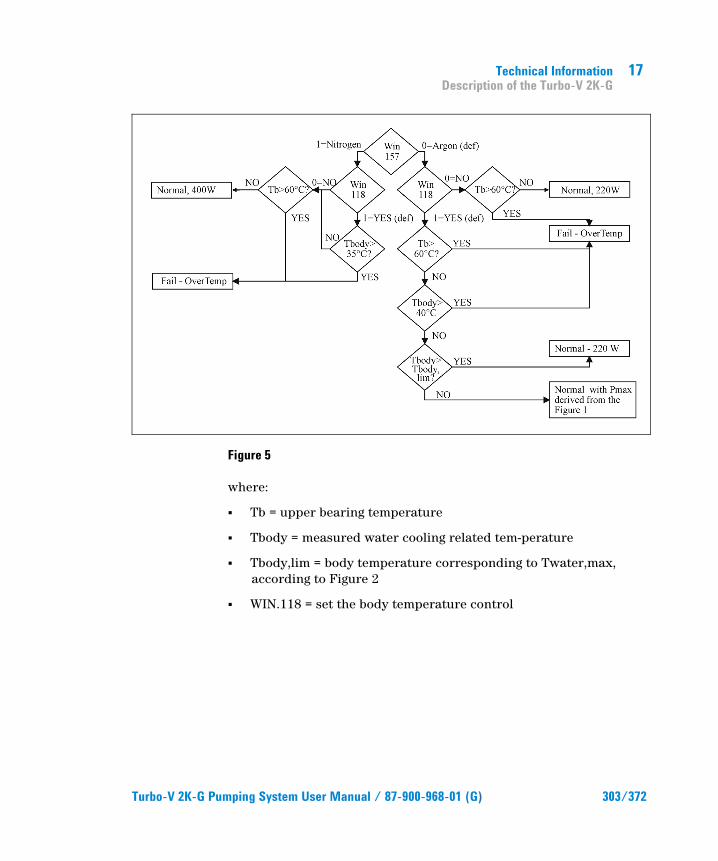
Technical Information Description of the Turbo-V 2K-G
17
Turbo-V 2K-G Pumping System User Manual / 87-900-968-01 (G) 303/372
Figure 5
where:
� Tb = upper bearing temperature
� Tbody = measured water cooling related tem-perature
� Tbody,lim = body temperature corresponding to Twater,max, according to Figure 2
� WIN.118 = set the body temperature control
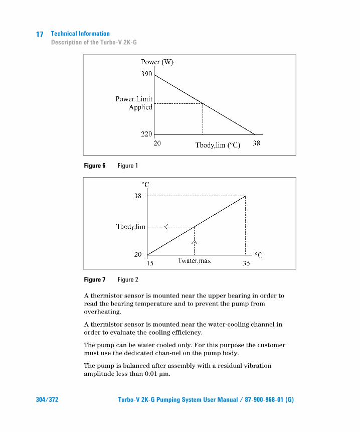
17 Technical Information Description of the Turbo-V 2K-G
304/372 Turbo-V 2K-G Pumping System User Manual / 87-900-968-01 (G)
Figure 6 Figure 1
Figure 7 Figure 2
A thermistor sensor is mounted near the upper bearing in order to read the bearing temperature and to prevent the pump from overheating.
A thermistor sensor is mounted near the water-cooling channel in order to evaluate the cooling efficiency.
The pump can be water cooled only. For this purpose the customer must use the dedicated chan-nel on the pump body.
The pump is balanced after assembly with a residual vibration amplitude less than 0.01 �m.

Technical Information Description of the Turbo-V 2K-G
17
Turbo-V 2K-G Pumping System User Manual / 87-900-968-01 (G) 305/372
The pump can operate in any position and must be supported on the high vacuum flange. The connection of the forevacuum on the side of the pump is a KF 40 NW flange.
Figure 8
Controller Description The dedicated controller is a solid-state frequency converter which is driven by a single chip micro-computer.
The controller can be operated by a remote host computer via the serial connection (a Windows-based software is available as an option), or by the remote I/O connector.
At every power-up the controller is in “Remote Mode” of operation and accepts only commands from J1 remote I/O connector. To put it in “Serial Mode” of operation please refer to the serial com-mand table.
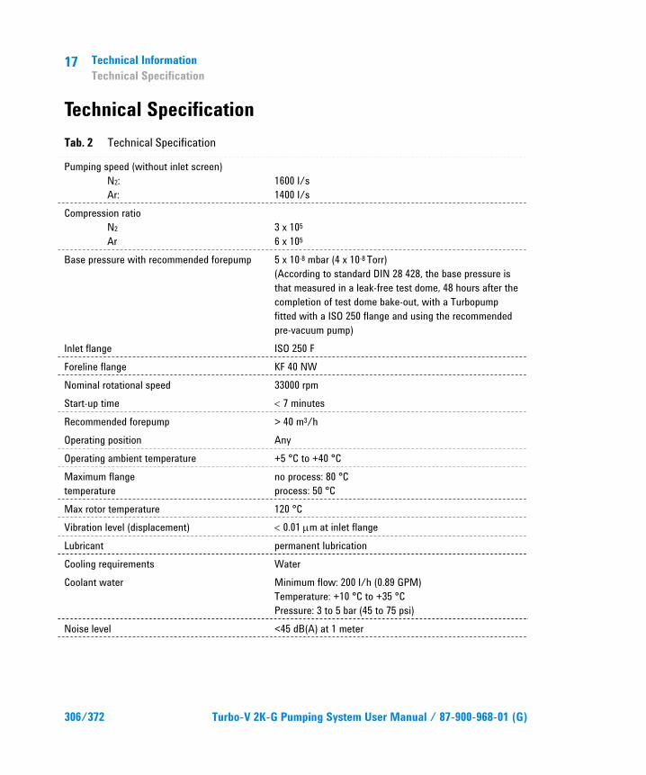
17 Technical Information Technical Specification
306/372 Turbo-V 2K-G Pumping System User Manual / 87-900-968-01 (G)
Technical Specification Tab. 2 Technical Specification
Pumping speed (without inlet screen) N2: Ar:
1600 l/s 1400 l/s
Compression ratio N2 Ar
3 x 10⁵ 6 x 10⁵
Base pressure with recommended forepump 5 x 10⁻⁸ mbar (4 x 10⁻⁸ Torr) (According to standard DIN 28 428, the base pressure is that measured in a leak-free test dome, 48 hours after the completion of test dome bake-out, with a Turbopump fitted with a ISO 250 flange and using the recommended pre-vacuum pump)
Inlet flange ISO 250 F Foreline flange KF 40 NW Nominal rotational speed 33000 rpm Start-up time � 7 minutes Recommended forepump > 40 m3/h Operating position Any Operating ambient temperature +5 °C to +40 °C Maximum flange temperature
no process: 80 °C process: 50 °C
Max rotor temperature 120 °C Vibration level (displacement) � 0.01 Pm at inlet flange Lubricant permanent lubrication Cooling requirements Water Coolant water Minimum flow: 200 l/h (0.89 GPM)
Temperature: +10 °C to +35 °C Pressure: 3 to 5 bar (45 to 75 psi)
Noise level <45 dB(A) at 1 meter

Technical Information Technical Specification
17
Turbo-V 2K-G Pumping System User Manual / 87-900-968-01 (G) 307/372
Power supply: Input voltage: Input freq.: Max input power: Stand-by power: Max operating power:
208 – 240 Vac 50 – 60 Hz 850 VA 30 to 35 W 400 W for Nitrogen and lighter gases 390 W for Argon
Protection fuse 2 x 8 A Compliance with: EN 55011 (Radio disturbance characteristics)
EN 61000-3-2 (Limits for harmonic current emissions) EN 61000-3-3 (Limitation of voltage changes, voltage fluctuations and flicker) EN 61000-6-2 and EN 61326 (Immunity for industrial environments) which recall: EN 61000-4-2 (Electrostatic discharge phenomena) EN 61000-4-3 (Radiated high-frequency phenomena) EN 61000-4-4, EN 61000-4-5, EN61000-4-6 (Conducted high-frequency phenomena) EN 61000-4-11 (Voltage fluctuation, voltage dips and short interruptions)
Installation Category II Pollution Degree 2 Max altitude 2000m MSL Power cable With European or NEMA plug 3 meters long (optional) Serial communication kit RS232 cable with a 9-pin D type male connector and a 9-
pin D type female connector, and Navigator software (optional)
Storage temperature -20 °C to +70 °C Environment protection IP54 Weight kg (lbs) 35 (77.16)
NOTE When the Turbo-V 2K-G has been stored at a temperature less than 5 °C, wait until the system has reached the above mentioned temperature before starting the pump.
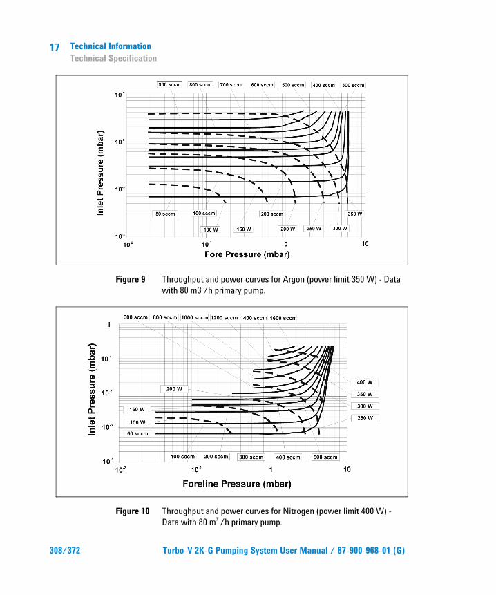
17 Technical Information Technical Specification
308/372 Turbo-V 2K-G Pumping System User Manual / 87-900-968-01 (G)
Figure 9 Throughput and power curves for Argon (power limit 350 W) - Data with 80 m3 /h primary pump.
Figure 10 Throughput and power curves for Nitrogen (power limit 400 W) - Data with 80 m3 /h primary pump.

Technical Information Turbo-V 2K-G Outline
17
Turbo-V 2K-G Pumping System User Manual / 87-900-968-01 (G) 309/372
Turbo-V 2K-G Outline The following figure shows the Turbo-V 2K-G outlines (dimensions are in mm [inches]).
Figure 11 Turbo-V 2K-G Navigator outline

17 Technical Information Interconnections
310/372 Turbo-V 2K-G Pumping System User Manual / 87-900-968-01 (G)
Interconnections The following paragraphs describe the Turbo-V 2K-G interconnections.
J1 – Remote I/O
Figure 12
This connector carries all the input and output sig-nals to remote control the Turbo-V 2K-G.
It is a 15-pins D type connector; the available sig-nals are detailed in the table, the following paragraphs describe the signal characteristics and use.
Tab. 3
PIN N. SIGNAL NAME INPUT/OUTPUT ISOLATION 1 START/STOP (+) IN Optocoupled 2 START/STOP (-) IN Optocoupled 3 INTERLOCK (+) IN Optocoupled 4 INTERLOCK (-) IN Optocoupled 5 SPEED SETTING (+) IN Optocoupled 6 FAULT COMMOMN OUT Relay 7 SOFT START (+) IN Optocoupled 8 SET POINT OUT Relay 9 +24 Vdc OUT Transformer 10 PURGE (+) IN Optocoupled 11 SET POINT OUT Relay

Technical Information Interconnections
17
Turbo-V 2K-G Pumping System User Manual / 87-900-968-01 (G) 311/372
PIN N. SIGNAL NAME INPUT/OUTPUT ISOLATION 12 VENT (+) IN Optocoupled 13 FAULT N.O. OUT Relay 14 ANALOG OUTPUT OUT Optocoupled 15 GROUND OUT Transformer
Signal Description START/STOP: input signal to start or stop the pump. With the supplied cover connector the START/STOP (+) signal is connected to the +24 Vdc pin and the START/STOP (-) signal to the GROUND pin: in this condition the pump doesn’t start.
INTERLOCK: input signal to confirm the pump rotation. With the supplied cover connector the INTERLOCK (+) signal is connected to the +24 Vdc pin and the INTERLOCK (-) signal to the GROUND pin, in this condition the pump automatically starts as soon as the controller recognises the input supply ("Plug & Pump").
SPEED SETTING: PWM input signal to set the pump speed. The PWM signal characteristics must be the following:
� frequency: 100 Hz +/-20%
� amplitude: high level from 12 to 24 V
� duty cycle range: from 25 % to 75 % corresponding to a pump speed from 475 Hz to 555 Hz linearly (see the following diagram).
Figure 13
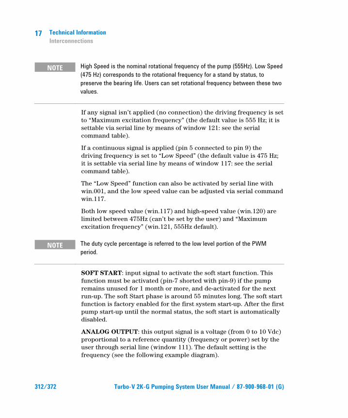
17 Technical Information Interconnections
312/372 Turbo-V 2K-G Pumping System User Manual / 87-900-968-01 (G)
NOTE High Speed is the nominal rotational frequency of the pump (555Hz). Low Speed (475 Hz) corresponds to the rotational frequency for a stand by status, to preserve the bearing life. Users can set rotational frequency between these two values.
If any signal isn’t applied (no connection) the driving frequency is set to “Maximum excitation frequency” (the default value is 555 Hz; it is settable via serial line by means of window 121: see the serial command table).
If a continuous signal is applied (pin 5 connected to pin 9) the driving frequency is set to “Low Speed” (the default value is 475 Hz; it is settable via serial line by means of window 117: see the serial command table).
The “Low Speed” function can also be activated by serial line with win.001, and the low speed value can be adjusted via serial command win.117.
Both low speed value (win.117) and high-speed value (win.120) are limited between 475Hz (can’t be set by the user) and “Maximum excitation frequency” (win.121, 555Hz default).
NOTE The duty cycle percentage is referred to the low level portion of the PWM period.
SOFT START: input signal to activate the soft start function. This function must be activated (pin-7 shorted with pin-9) if the pump remains unused for 1 month or more, and de-activated for the next run-up. The soft Start phase is around 55 minutes long. The soft start function is factory enabled for the first system start-up. After the first pump start-up until the normal status, the soft start is automatically disabled.
ANALOG OUTPUT: this output signal is a voltage (from 0 to 10 Vdc) proportional to a reference quantity (frequency or power) set by the user through serial line (window 111). The default setting is the frequency (see the following example diagram).
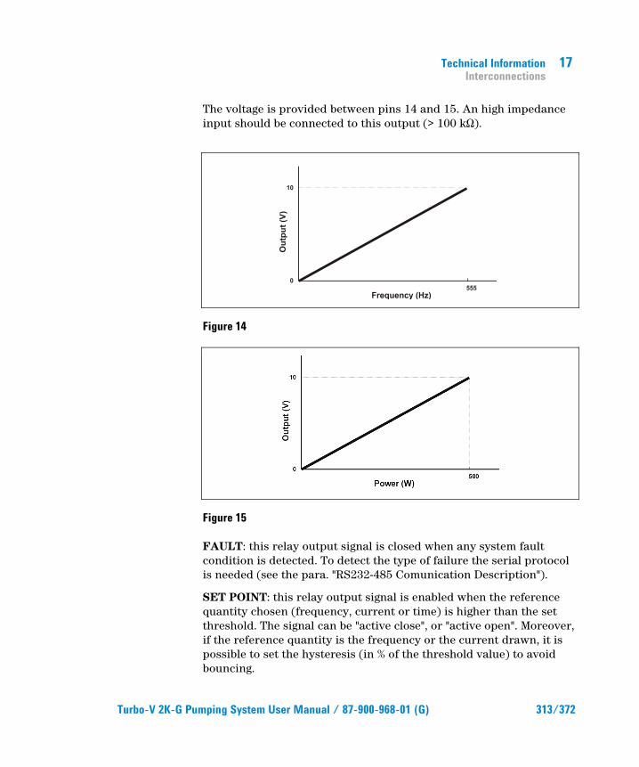
Technical Information Interconnections
17
Turbo-V 2K-G Pumping System User Manual / 87-900-968-01 (G) 313/372
The voltage is provided between pins 14 and 15. An high impedance input should be connected to this output (> 100 kƄ).
Figure 14
Figure 15
FAULT: this relay output signal is closed when any system fault condition is detected. To detect the type of failure the serial protocol is needed (see the para. "RS232-485 Comunication Description").
SET POINT: this relay output signal is enabled when the reference quantity chosen (frequency, current or time) is higher than the set threshold. The signal can be "active close", or "active open". Moreover, if the reference quantity is the frequency or the current drawn, it is possible to set the hysteresis (in % of the threshold value) to avoid bouncing.

17 Technical Information Interconnections
314/372 Turbo-V 2K-G Pumping System User Manual / 87-900-968-01 (G)
For example:
� reference quantity: frequency (window 101=0)
� threshold: 500 Hz (window 102=500)
� hysteresis: 1% (window 103=1)
� activation type: "active close" (window 104=1)
Figure 16
The set point output stays open until the frequency becomes higher than 505 Hz (that is 500 Hz + 1% of 500 Hz), then the output goes closed and stays colsed until the frequency becomes lower than 495 Hz (that is 500 Hz – 1% of 500 Hz).
It is possible to mask the set point checking for a programmable mask time (window 103).
The SET POINT signal has the following default settings:
� reference quantity: controller status
� thereshold: not relevant
� hysteresis: not relevant
� activation type: active close (NO)
� delay time: 0 second
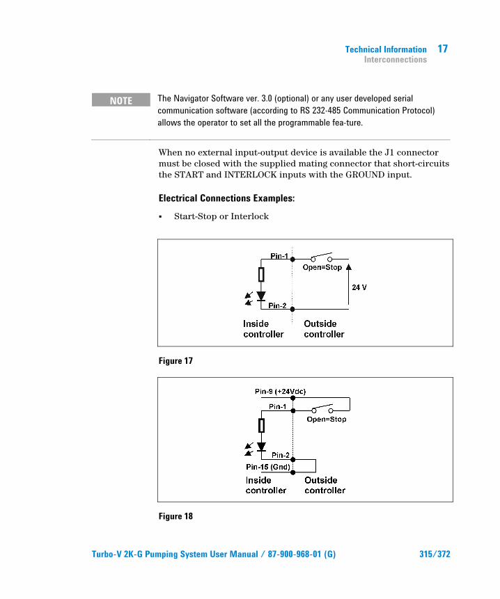
Technical Information Interconnections
17
Turbo-V 2K-G Pumping System User Manual / 87-900-968-01 (G) 315/372
NOTE The Navigator Software ver. 3.0 (optional) or any user developed serial communication software (according to RS 232-485 Communication Protocol) allows the operator to set all the programmable fea-ture.
When no external input-output device is available the J1 connector must be closed with the supplied mating connector that short-circuits the START and INTERLOCK inputs with the GROUND input.
Electrical Connections Examples: � Start-Stop or Interlock
Figure 17
Figure 18
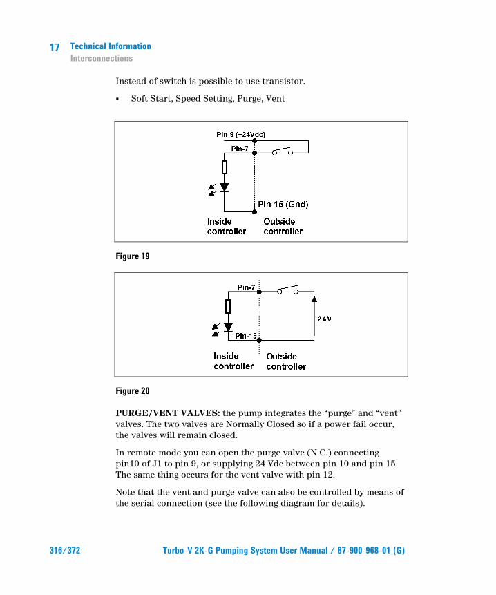
17 Technical Information Interconnections
316/372 Turbo-V 2K-G Pumping System User Manual / 87-900-968-01 (G)
Instead of switch is possible to use transistor.
� Soft Start, Speed Setting, Purge, Vent
Figure 19
Figure 20
PURGE/VENT VALVES: the pump integrates the “purge” and “vent” valves. The two valves are Normally Closed so if a power fail occur, the valves will remain closed.
In remote mode you can open the purge valve (N.C.) connecting pin10 of J1 to pin 9, or supplying 24 Vdc between pin 10 and pin 15. The same thing occurs for the vent valve with pin 12.
Note that the vent and purge valve can also be controlled by means of the serial connection (see the following diagram for details).

Technical Information Interconnections
17
Turbo-V 2K-G Pumping System User Manual / 87-900-968-01 (G) 317/372
Win125
Win146
1=OnCommand 0=Auto (def)
Pin-10 Low -> Purge ClosePin-10 High -> Purge OpenPin-12 Low ->Vent ClosePin-12 High -> Vent Open
1=Remote-I/O
0=Serial (def)
win.122=0 Vent Close (def)win.122=1 Vent Openwin.145=0 Purge Close (def)win.145=1 Purge Open
Win.126 set the “Vent Valve Opening Delay”, from 0 to 65535, 1bit=0.2s, def=10s=50bitWin.147 set the “Vent Valve Open Time”, from 0 to 65535, 1bit=0.2s, def=0=infinite
Start Command
Stop Ramp Normal AutoTunBreaking
Stop Command
Stop
Win.126
Win.147
If win.147=0
Purge
Vent
O
O
C
C
Fail -> Vent and Purge = ClosedPower Fail -> Purge and Vent = Closed
Figure 21
J2 – Serial
Figure 22
This is a 9 pin D-type serial input/output connector to control via an RS 232 or RS 485 connection the Turbo-V "K-G.
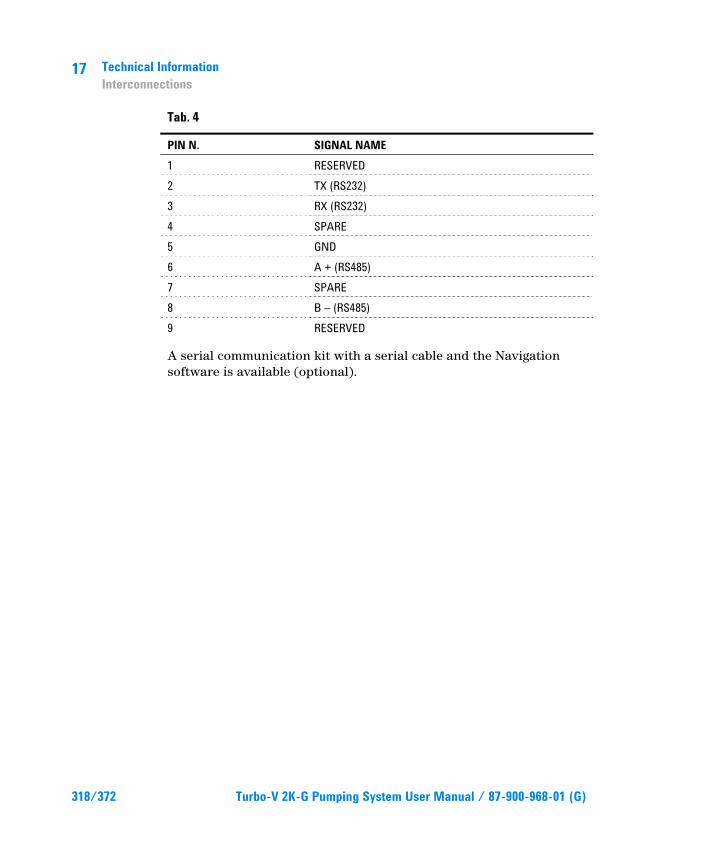
17 Technical Information Interconnections
318/372 Turbo-V 2K-G Pumping System User Manual / 87-900-968-01 (G)
Tab. 4
PIN N. SIGNAL NAME 1 RESERVED 2 TX (RS232) 3 RX (RS232) 4 SPARE 5 GND 6 A + (RS485) 7 SPARE 8 B – (RS485) 9 RESERVED
A serial communication kit with a serial cable and the Navigation software is available (optional).

Technical Information Serial Cable Installation
17
Turbo-V 2K-G Pumping System User Manual / 87-900-968-01 (G) 319/372
Serial Cable Installation In order to maintain the IP-54 protection level, please use a certified IP-54 connector or the one provided by Agilent.
RS 232/RS 485 Communication Description Both the RS 232 and the RS 485 interfaces are available on the connector P2.
The communication protocol is the same (see the structure below), but only the RS 485 manages the address field. Therefore to enable the RS 485 is necessary to select the type of communication as well as the device address by means of the Navi-gator software.
Communication Format � 8 data bit
� no parity
� 1 stop bit
� baud rate: 600/1200/2400/4800/9600 pro-grammable
Communication Protocol The communication protocol is a MASTER/SLAVE type where:
� Host = MASTER
� Controller = SLAVE
The communication is performed in the following way:
1. the host (MASTER) send a MESSAGE + CRC to the controller (SLAVE);
2. the controller answer with an ANSWER + CRC to the host.
The MESSAGE is a string with the following format:
<STX>+<ADDR>+<WIN>+<COM>+<DATA>+<ETX>+<CRC>
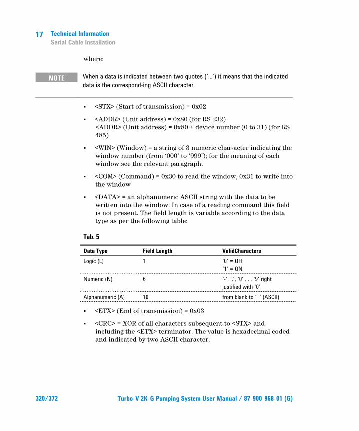
17 Technical Information Serial Cable Installation
320/372 Turbo-V 2K-G Pumping System User Manual / 87-900-968-01 (G)
where:
NOTE When a data is indicated between two quotes (‘...’) it means that the indicated data is the correspond-ing ASCII character.
� <STX> (Start of transmission) = 0x02
� <ADDR> (Unit address) = 0x80 (for RS 232) <ADDR> (Unit address) = 0x80 + device number (0 to 31) (for RS 485)
� <WIN> (Window) = a string of 3 numeric char-acter indicating the window number (from ‘000’ to ‘999’); for the meaning of each window see the relevant paragraph.
� <COM> (Command) = 0x30 to read the window, 0x31 to write into the window
� <DATA> = an alphanumeric ASCII string with the data to be written into the window. In case of a reading command this field is not present. The field length is variable according to the data type as per the following table:
Tab. 5
Data Type Field Length ValidCharacters Logic (L) 1 ‘0’ = OFF
‘1’ = ON Numeric (N) 6 ‘-‘, ‘.’, ‘0’ . . . ‘9’ right
justified with ‘0’ Alphanumeric (A) 10 from blank to ‘_’ (ASCII)
� <ETX> (End of transmission) = 0x03
� <CRC> = XOR of all characters subsequent to <STX> and including the <ETX> terminator. The value is hexadecimal coded and indicated by two ASCII character.

Technical Information Serial Cable Installation
17
Turbo-V 2K-G Pumping System User Manual / 87-900-968-01 (G) 321/372
The addressed SLAVE will respond with an ANSWER whose structure depends from the MESSAGE type.
When the MESSAGE is a reading command, the SLAVE will respond transmitting a string with the same structure of the MESSAGE.
NOTE Some error settings are foreseen:
Tab. 6
0x15 NACK foreseen with Read/Write commands 0x32 UNKNOWN WINDOW
0x33 BAD DATA TYPE foreseen only with Write commands 0x34 OUT OF RANGE
0x35 BAD OPERATION
NOTE Using the RS 485 interface, the message structure re-mains identical to the one used for the RS 232 interface, the only difference being that the value assigned to the ADDRESS <ADDR>.
The controller can answers with the following response types:
Tab. 7 Response types
Type Length Value Description Logic 1 byte - After a read instruction of a logic window Numeric 6 bytes - After a read instruction of a numeric window Alphanumeric 10 bytes - After a read instruction of an alphanumeric
window ACK 1 byte (0x6) The command execution has been
successfully completed NACK 1 byte (0x15) The command execu-tion has been failed Unknown Window
1 byte (0x32) The specified window in the command is not a valid window
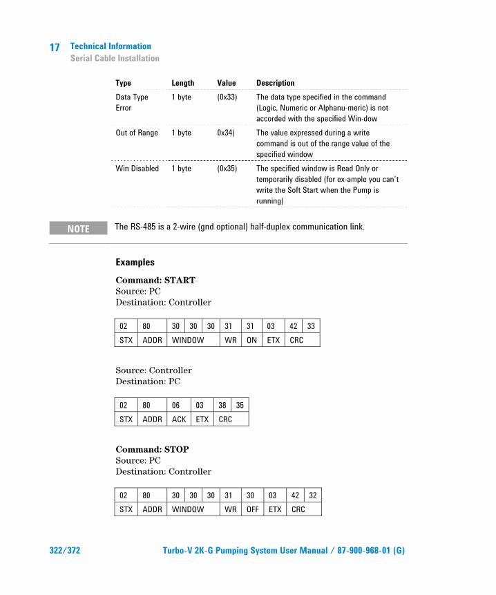
17 Technical Information Serial Cable Installation
322/372 Turbo-V 2K-G Pumping System User Manual / 87-900-968-01 (G)
Type Length Value Description Data Type Error
1 byte (0x33) The data type specified in the command (Logic, Numeric or Alphanu-meric) is not accorded with the specified Win-dow
Out of Range 1 byte 0x34) The value expressed during a write command is out of the range value of the specified window
Win Disabled 1 byte (0x35) The specified window is Read Only or temporarily disabled (for ex-ample you can’t write the Soft Start when the Pump is running)
NOTE The RS-485 is a 2-wire (gnd optional) half-duplex communication link.
Examples Command: START Source: PC Destination: Controller 02 80 30 30 30 31 31 03 42 33 STX ADDR WINDOW WR ON ETX CRC
Source: Controller Destination: PC 02 80 06 03 38 35 STX ADDR ACK ETX CRC
Command: STOP Source: PC Destination: Controller 02 80 30 30 30 31 30 03 42 32 STX ADDR WINDOW WR OFF ETX CRC

Technical Information Serial Cable Installation
17
Turbo-V 2K-G Pumping System User Manual / 87-900-968-01 (G) 323/372
Source: Controller Destination: PC 02 80 06 03 38 35 STX ADDR ACK ETX CRC
Command: SOFT-START (ON) Source: PC Destination: Inverter 02 80 31 30 30 31 31 03 42 32 STX ADDR WINDOW WR ON ETX CRC
Source: Inverter Destination: PC 02 80 06 03 38 35 STX ADDR ACK ETX CRC
Command: SOFT-START (OFF) Source: PC Destination: Inverter 02 80 31 30 30 31 30 03 42 33 STX ADDR WINDOW WR OFF ETX CRC
Source: Inverter Destination: PC 02 80 06 03 38 35 STX ADDR ACK ETX CRC

17 Technical Information Serial Cable Installation
324/372 Turbo-V 2K-G Pumping System User Manual / 87-900-968-01 (G)
Command: READ PUMP STATUS Source: PC Destination: Controller (with address = 3) 02 83 32 30 35 30 03 38 37 STX ADDR WINDOW RD ETX CRC
Source: Controller (with address = 3 in stop status) Destination: PC 02 83 32 30 35 30 30 30 30 30 30 03 38 37 STX ADDR WINDOW DATA (STATUS) ETX CRC
Command: READ SERIAL CONFIGURATION Source: PC Destination: Controller (with address = 3 in 485 mode) 02 83 35 30 34 30 03 38 31 STX ADDR WINDOW RD ETX CRC
Source: Controller Destination: PC 02 83 35 30 34 30 31 03 42 30 STX ADDR WINDOW RD DATA ETX CRC

Technical Information Serial Cable Installation
17
Turbo-V 2K-G Pumping System User Manual / 87-900-968-01 (G) 325/372
Window Meanings Tab. 8
N. Read/ Write Data Type
Description Admitted Values
000 R/W L Start/Stop (in remote mode the window is a read only)
Start = 1 Stop = 0
008 R/W L Remote (default) or Serial configuration
Remote = 1 Serial = 0 (default = 1)
100 R/W L Soft Start (write only in Stop condition)
YES = 1 NO = 0
101 R/W N Set Point type 0 = Frequency 1 = Current 2 = Time (default = 0)
102 R/W N Set Point threshold (expressed in Hz, mA or s)
(default = 500)
103 R/W N Set Point mask: time between the pump start and the set point check (seconds)
0 to 99999 (default = 0)
104 R/W L Set Point signal activation type: the signal can be "N.O." or "N.C."
0 = active close (N.O.) 1 = active open (N.C.) (default = 0)
105 R/W N Set point hysteresis (in % of threshold)
0 to 100 (default = 2)
108 R/W N Baud rate 600 = 0 1200 = 1 2400 = 2 4800 = 3 9600 = 4 (default = 4)
109 W L Pump life/ cycle time/ cycle number reset
To reset write ‘1’

17 Technical Information Serial Cable Installation
326/372 Turbo-V 2K-G Pumping System User Manual / 87-900-968-01 (G)
N. Read/ Write Data Type
Description Admitted Values
111 R/W L Analog output type: output voltage signal proportional to frequency or power
0 = frequency 1 = power (default = 0)
114 R/W N Purge gas type 0 = N2 1 = Ar
115 R/W L Threshold flowmeter sccm 117 R/W N Low speed setting (Hz) 475 to win. 121
(default = 475) 118 R/W L Body thermistor enable 0 = NO
1 = YES 120 R/W N High speed setting (Hz) 475 to win. 121
(default = 555) 121 R/W N Maximum excitation frequency
in Hz (active only in Stop condition)
475 to 555 (default = 555)
122 R/W L Set vent valve open/close (N.C.) 1 = open 0 = close (default = 0)
123 124
Reserved to Agilent service
125 R/W L Valves operating mode 0 = auto (default) 1 = on command (see win.146)
126 R/W N Vent valve opening delay (expressed in 0.2 sec)
0 to 65535 (corresponding to 0 to 13107 sec) (default = 15)
130 Reserved to Agilent service 145 R/W L Set purge valve open/close 0 = close
1 = open (default = 0)
146 R/W L Set valves command source 0 = Serial 1 = Remote (default = 0)

Technical Information Serial Cable Installation
17
Turbo-V 2K-G Pumping System User Manual / 87-900-968-01 (G) 327/372
N. Read/ Write Data Type
Description Admitted Values
147 R/W N Vent Valve Opening Time (expressed in 0.2 sec)
0 to 65535 bit (0=infinite, 1=0.2sec, max=13107 sec) (default =0)
152 R/W L HPS enable 0 = OFF 1 = ON (default = 0) write only in STOP
155 R N Power limit applied Watt 157 R/W L Gas load type 0 = Ar
1 = N2 (default = 0)
158 R/W N Max foreseen water cooling temperature (Twater,max)
°C, min = 15 max = 35 (default = 34)
159 R/W N Water cooling hysteresYs % (default = 1) 164 R N Tbody,lim: body temperature corresponding to Twater,max 200 R N Pump current in mA dc 201 R N Pump voltage in Vdc 202 R N Pump power in W (pump current
x pump voltage duty cycle)
203 R N Driving frequency in Hz 204 R N Pump temperature in °C 0 to 70 205 R N Pump status Stop = 0
Waiting intlk = 1 Starting = 2 Auto-tuning = 3 Braking = 4 Normal = 5 Fail = 6
206 R N Error code Bit description: see the following figure
211 R N Controller temperature n. 1 °C 216 R N Pump body temperature °C

17 Technical Information Serial Cable Installation
328/372 Turbo-V 2K-G Pumping System User Manual / 87-900-968-01 (G)
N. Read/ Write Data Type
Description Admitted Values
222 R N Controller temperature n. 2 °C 223 R N Flow meter reading sccm 300 R N Cycle time in minutes (zeroed by
the reset command) 0 to 999999
301 R N Cycle number (zeroed by the reset command)
0 to 9999
302 R N Pump life in hours (zeroed by the reset command)
0 to 999999
303 R N High Power Start cycles number 304 R N High Power Start tries number of
last 9
310 to 399
Reserved to Agilent service
400 R A CRC EPROM (QE) QE8XXXX (where “XXXX” are variable)
402 R A CRC Param. (PA) PA8XXXX (where “XXXX” are variable)
502 Reserved to Agilent service 503 R/W N RS 485 address 0 to 31 (default = 0) 504 R/W L Serial type select 0 = RS 232
1 = RS 485 (default = 0)

Technical Information Serial Cable Installation
17
Turbo-V 2K-G Pumping System User Manual / 87-900-968-01 (G) 329/372
7 6 5 4 3 2 1 0
TOO HIGH LOAD NO CONNECTION
SHORT CIRCUIT PUMP OVERTEMP.
OVERVOLTAGE CONTROLL. OVERTEMP.
AUX FAIL POWER FAIL
Figure 23 Window N. 206 Bit Description
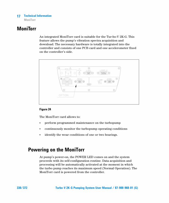
17 Technical Information MoniTorr
330/372 Turbo-V 2K-G Pumping System User Manual / 87-900-968-01 (G)
MoniTorr An integrated MoniTorr card is suitable for the Tur-bo-V 2K-G. This feature allows the pump’s vibration spectra acquisition and download. The necessary hardware is totally integrated into the controller and consists of one PCB card and one accelerometer fixed on the controller’s side.
Figure 24
The MoniTorr card allows to:
� perform programmed maintenance on the turbopump
� continuously monitor the turbopump operating conditions
� identify the wear conditions of one or two bearings.
Powering on the MoniTorr At pump’s power-on, the POWER LED comes on and the system proceeds with its self-configuration routine. Data acquisition and processing will be automatically activated at the moment in which the turbo pump reaches its maximum speed (Normal Operation). The MoniTorr card is powered from the controller.
Technical Information MoniTorr
17
Turbo-V 2K-G Pumping System User Manual / 87-900-968-01 (G) 331/372
Operation At predefined intervals, the Monitorr will also acquire the data related to the vibration spectrums, power and temperature in addition to other data detected by the Turbo controller. All the data must be transferred to a PC (by means of the “File Download” program) where are stored and where can be analyzed by Agilent’s specialised person-nel.
Maintenance The MoniTorr card doesn’t require any mainte-nance. Any intervention must be carried out by authorised personnel.
In case of failure, the Agilent Repair Service is available or Advanced Exchange Service that pro-vides you with a regenerated controller in replacement of the faulty one.
MoniTorr Installation on the Network and on the Main PC
The RS-485 interface allows connecting more than one system in network (up to 32). In this way it is possible to download all the spectrums data with a single PC through a protocol converter (not yet available) which operate as a gateway from 485 to 232 link.
The controller provides the serial address of the MoniTorr option. Every controller must therefore have a different serial address so as to avoid conflicts on the network. Every controller has “0” default serial address. So the user must set the controller’s address.
The following figure shows the connection of the MoniTorr to the RS485 network.

17 Technical Information MoniTorr
332/372 Turbo-V 2K-G Pumping System User Manual / 87-900-968-01 (G)
Figure 25 Network connection
NOTE The protocol converter is not strictly needed for MoniTorr operation. It is also possible to use the standard RS232 to RS485 converter and the standard optical to RS232 converter.
In order to install and operate the MoniTorr card of the Turbo-V 2K-G it’s necessary to get the Monitor Connectivity Kit (P/N 969-9260). The user should install it on any windows based PC with at least one RS232 port.
MoniTorr Connectivity Kit Installation Procedure 1 Install the File VT Serial Address Configurator on PC (launch VT-
SAC\setup.exe on CD Rom)
2 Connect the RS232 cable between the PC se-rial port and the first TV 2KG serial port
Figure 26
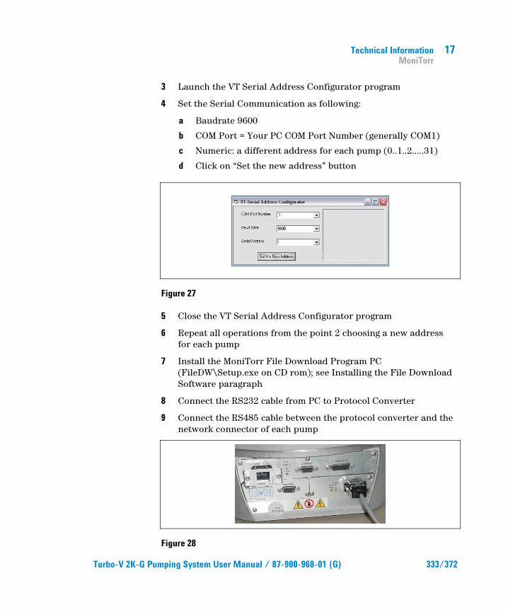
Technical Information MoniTorr
17
Turbo-V 2K-G Pumping System User Manual / 87-900-968-01 (G) 333/372
3 Launch the VT Serial Address Configurator program
4 Set the Serial Communication as following:
a Baudrate 9600
b COM Port = Your PC COM Port Number (generally COM1)
c Numeric: a different address for each pump (0..1..2…..31)
d Click on “Set the new address” button
Figure 27
5 Close the VT Serial Address Configurator program
6 Repeat all operations from the point 2 choosing a new address for each pump
7 Install the MoniTorr File Download Program PC (FileDW\Setup.exe on CD rom); see Installing the File Download Software paragraph
8 Connect the RS232 cable from PC to Protocol Converter
9 Connect the RS485 cable between the protocol converter and the network connector of each pump
Figure 28

17 Technical Information MoniTorr
334/372 Turbo-V 2K-G Pumping System User Manual / 87-900-968-01 (G)
10 Check if Baud Rate of protocol converter is fixed at 115K2 (switch between 9 position and F position)
Figure 29
11 Connect the power supply to protocol converter
12 Launch the file download software
13 Select menu File/Download Mode and check the following fields:
� Trigger 1
� Mode: Number of file (# file)
14 Select menu File/Archive Time and select the number of days for a periodical file download to be sent (for example 7 days)
15 Read the Archive Saving Method Procedure Paragraph
16 Start the system
NOTE The computer must be always connected to the MoniTorr. Please, be sure that the PC hasn’t au-tomatically Standby or Suspend procedure active.
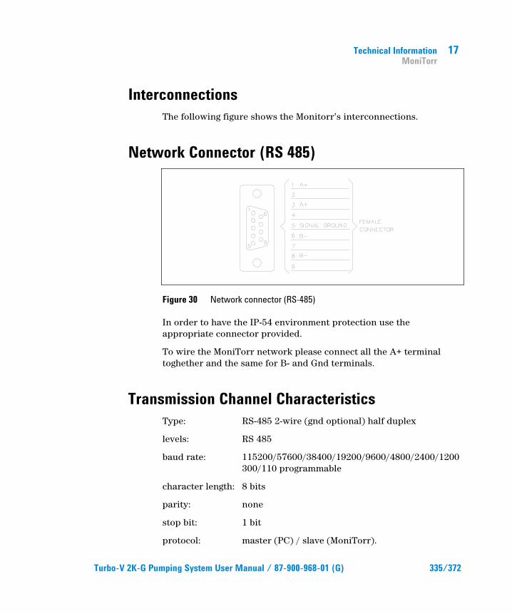
Technical Information MoniTorr
17
Turbo-V 2K-G Pumping System User Manual / 87-900-968-01 (G) 335/372
Interconnections The following figure shows the Monitorr’s interconnections.
Network Connector (RS 485)
Figure 30 Network connector (RS-485)
In order to have the IP-54 environment protection use the appropriate connector provided.
To wire the MoniTorr network please connect all the A+ terminal toghether and the same for B- and Gnd terminals.
Transmission Channel Characteristics Type: RS-485 2-wire (gnd optional) half duplex
levels: RS 485
baud rate: 115200/57600/38400/19200/9600/4800/2400/1200 300/110 programmable
character length: 8 bits
parity: none
stop bit: 1 bit
protocol: master (PC) / slave (MoniTorr).
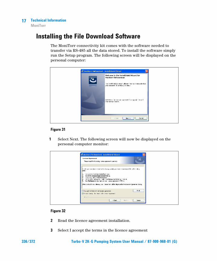
17 Technical Information MoniTorr
336/372 Turbo-V 2K-G Pumping System User Manual / 87-900-968-01 (G)
Installing the File Download Software The MoniTorr connectivity kit comes with the software needed to transfer via RS-485 all the data stored. To install the software simply run the Setup program. The following screen will be displayed on the personal computer:
Figure 31
1 Select Next. The following screen will now be displayed on the personal computer monitor:
Figure 32
2 Read the licence agreement installation.
3 Select I accept the terms in the licence agreement
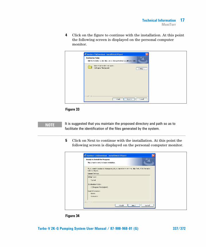
Technical Information MoniTorr
17
Turbo-V 2K-G Pumping System User Manual / 87-900-968-01 (G) 337/372
4 Click on the figure to continue with the installation. At this point the following screen is displayed on the personal computer monitor.
Figure 33
NOTE It is suggested that you maintain the proposed directory and path so as to facilitate the identification of the files generated by the system.
5 Click on Next to continue with the installation. At this point the following screen is displayed on the personal computer monitor.
Figure 34

17 Technical Information MoniTorr
338/372 Turbo-V 2K-G Pumping System User Manual / 87-900-968-01 (G)
6 Select Install to go on with the installation. Thefollowing screen is displayed on the personal computer monitor.
Figure 35
7 Select Finish to conclude the installation.
NOTE If during installation the program finds some system files that are out of date, you will be prompted to restart the computer. In this case proceed to restart the computer and repeat the installation procedure.
Operating Procedure Proceed as follows to correctly use the controller:
1 Power on the system. The related LED on the front panel will come on.
The MoniTorr detects when the pump's maximum rotation speed is reached. At this point the acquisition and analysis of the data deriving from the pump begins and is signalled by the flashing of the Data Acquisition LED (yellow).

Technical Information MoniTorr
17
Turbo-V 2K-G Pumping System User Manual / 87-900-968-01 (G) 339/372
Download Software The File Download program acquires the file from the MoniTorrs connected in the network and stores them on hard disk. This is automatically performed by the program when it is launched, or at regular intervals depending on the parameters set.
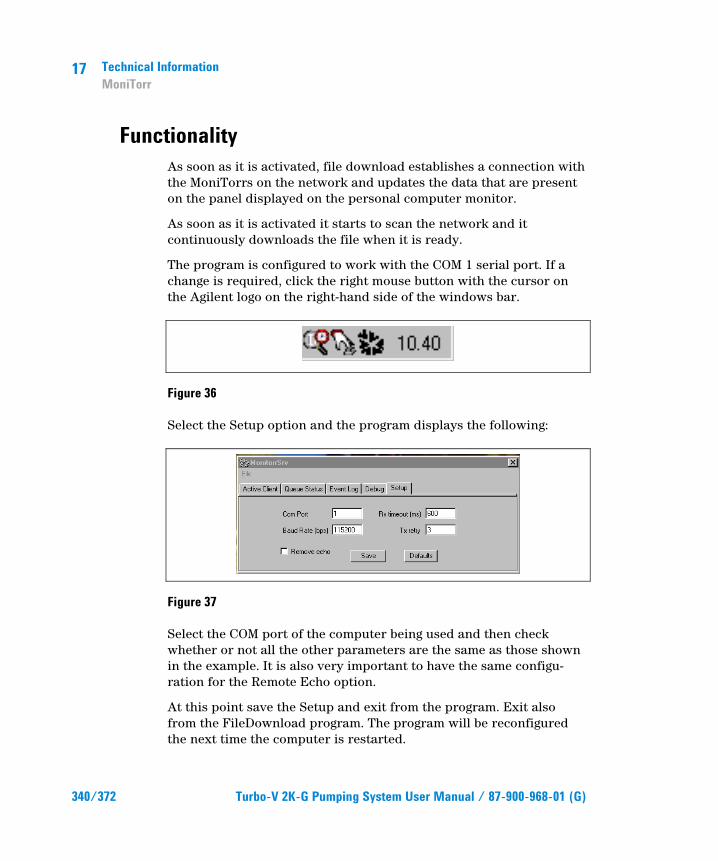
17 Technical Information MoniTorr
340/372 Turbo-V 2K-G Pumping System User Manual / 87-900-968-01 (G)
Functionality As soon as it is activated, file download establishes a connection with the MoniTorrs on the network and updates the data that are present on the panel displayed on the personal computer monitor.
As soon as it is activated it starts to scan the network and it continuously downloads the file when it is ready.
The program is configured to work with the COM 1 serial port. If a change is required, click the right mouse button with the cursor on the Agilent logo on the right-hand side of the windows bar.
Figure 36
Select the Setup option and the program displays the following:
Figure 37
Select the COM port of the computer being used and then check whether or not all the other parameters are the same as those shown in the example. It is also very important to have the same configu-ration for the Remote Echo option.
At this point save the Setup and exit from the program. Exit also from the FileDownload program. The program will be reconfigured the next time the computer is restarted.
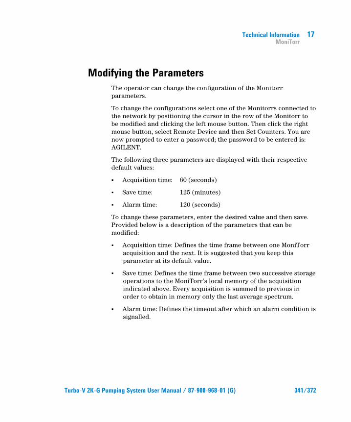
Technical Information MoniTorr
17
Turbo-V 2K-G Pumping System User Manual / 87-900-968-01 (G) 341/372
Modifying the Parameters The operator can change the configuration of the Monitorr parameters.
To change the configurations select one of the Monitorrs connected to the network by positioning the cursor in the row of the Monitorr to be modified and clicking the left mouse button. Then click the right mouse button, select Remote Device and then Set Counters. You are now prompted to enter a password; the password to be entered is: AGILENT.
The following three parameters are displayed with their respective default values:
� Acquisition time: 60 (seconds)
� Save time: 125 (minutes)
� Alarm time: 120 (seconds)
To change these parameters, enter the desired value and then save. Provided below is a description of the parameters that can be modified:
� Acquisition time: Defines the time frame between one MoniTorr acquisition and the next. It is suggested that you keep this parameter at its default value.
� Save time: Defines the time frame between two successive storage operations to the MoniTorr’s local memory of the acquisition indicated above. Every acquisition is summed to previous in order to obtain in memory only the last average spectrum.
� Alarm time: Defines the timeout after which an alarm condition is signalled.

17 Technical Information MoniTorr
342/372 Turbo-V 2K-G Pumping System User Manual / 87-900-968-01 (G)
Archive Saving Method Procedure Periodically (every Archive Time days) the file download program creates a file .cab (special compressed Microsoft Windows file) with the name of the registration day. In the file download window the customer can view a new text on green back screen with the date of the registration. By clicking on the OK button automatically an explore window* appears on the screen. You will find some acquisition files (*.mon) and a compressed archive file named according to the registration day (date.CAB). The customer should send by e-mail the compressed (.CAB) file every archive time period to Agilent Technical support at the following address: [email protected]
Figure 38
*Only for information: all files are automatically stored in the directory C:\Agilent\
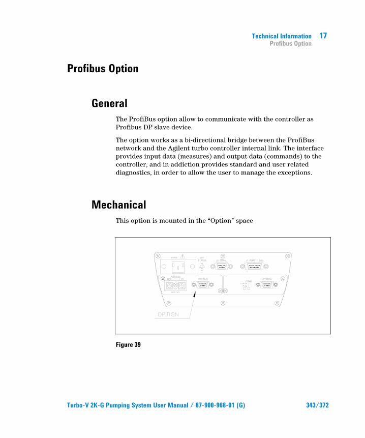
Technical Information Profibus Option
17
Turbo-V 2K-G Pumping System User Manual / 87-900-968-01 (G) 343/372
Profibus Option
General The ProfiBus option allow to communicate with the controller as Profibus DP slave device.
The option works as a bi-directional bridge between the ProfiBus network and the Agilent turbo controller internal link. The interface provides input data (measures) and output data (commands) to the controller, and in addiction provides standard and user related diagnostics, in order to allow the user to manage the exceptions.
Mechanical This option is mounted in the “Option” space
Figure 39

17 Technical Information Profibus Option
344/372 Turbo-V 2K-G Pumping System User Manual / 87-900-968-01 (G)
Installation This option can be factory installed or on the field by Agilent personnel.
The profibus connector pin-out is reported in the following figure. Please in order to obtain best performance use profibus certified cables.
CAUTION! To maintain the IP-54 protection level, use the appropriate connector provided with the pump.
Figure 40 ProfiBus connector
Configuration Before power-on the controller set the Profibus address by the 2 rotary switches.
Up to 126 different addresses (from 0 to 125) can be selected. The address value sets by the 2 switches is expressed in hexadecimal notation, so value from 00 to 7D are permitted; this setting is read by the interface during the power-on phase, so any change of the switch position after the power-on is ignored.
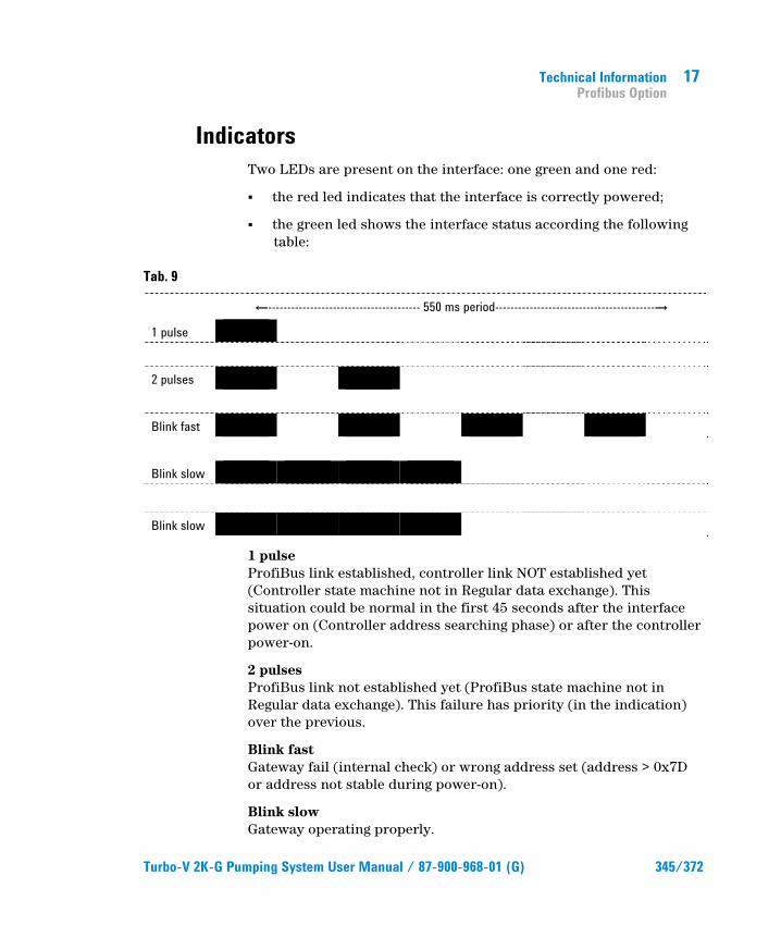
Technical Information Profibus Option
17
Turbo-V 2K-G Pumping System User Manual / 87-900-968-01 (G) 345/372
Indicators Two LEDs are present on the interface: one green and one red:
� the red led indicates that the interface is correctly powered;
� the green led shows the interface status according the following table:
Tab. 9
ȸ---------------------------------------- 550 ms period------------------------------------------Ⱥ 1 pulse
2 pulses
Blink fast
Blink slow
Blink slow
1 pulse ProfiBus link established, controller link NOT established yet (Controller state machine not in Regular data exchange). This situation could be normal in the first 45 seconds after the interface power on (Controller address searching phase) or after the controller power-on.
2 pulses ProfiBus link not established yet (ProfiBus state machine not in Regular data exchange). This failure has priority (in the indication) over the previous.
Blink fast Gateway fail (internal check) or wrong address set (address > 0x7D or address not stable during power-on).
Blink slow Gateway operating properly.

17 Technical Information Profibus Option
346/372 Turbo-V 2K-G Pumping System User Manual / 87-900-968-01 (G)
Software Operation and State Machine From the software point of view, the interface can be seen as two devices (one for ProfiBus and the other for the internal link) linked together.
Each device has its own state machine to manage the device operation.
Figure 41
Tab. 10 Profibus State Machine
PROFIBUS STATE MACHINE Status Meaning POWER_ON Interface set-up WAIT_PRM Wait for parameterisation from the master WAIT_CFG Wait for configuration from the master DATA_EX Regular data exchange

Technical Information Profibus Option
17
Turbo-V 2K-G Pumping System User Manual / 87-900-968-01 (G) 347/372
Figure 42
Tab. 11 Internal Link State Machine
INTERNAL LINK STATE MACHINE Status Meaning POWER_ON Interface set-up SRC_ADDR Search for the controller serial address IDENTIFY Identify controller model and protocol DATA_EX Regular data exchange
The two machines continuously share I/O data with the relative bus, and interact each other only in following conditions:
� ProfiBus Data Exchange is suspended (static diagnosis activated) if the internal serial link in not established
� Internal serial link Data Exchange is suspended (only for output data) if the ProfiBus State machine is not in Data Exchange mode
As a general rule, unrecoverable communication errors make each machine to jump to the state immediately following the power-on state (WAIT_PRM or SRC_ADDR).

17 Technical Information Profibus Option
348/372 Turbo-V 2K-G Pumping System User Manual / 87-900-968-01 (G)
Message Mapping The communication is based on the continuous data exchange capability of the ProfiBus standard, where the master sends continuously the entire slave configuration and reads back the entire slave status.
For this purpose one Input (from slave to master) and one Output (from master to slave) buffers are provided. All the needed parameters are mapped inside each buffer.
The following tables summarise the ProfiBus parameter access, related to the corresponding windows serial protocol (for this protocol please refers to the serial interface paragraph).
The interface doesn’t any scaling operation on the read/written parameters. It acts only as a gateway between the ProfiBus network and the pump’s controller serial interface. As a consequence of this, the scale and the meaning of some parameters depends directly to the specific model of Turbo Pump controller connected to the interface.
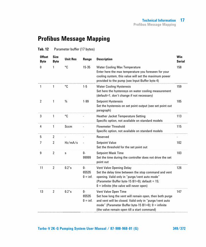
Technical Information Profibus Message Mapping
17
Turbo-V 2K-G Pumping System User Manual / 87-900-968-01 (G) 349/372
Profibus Message Mapping Tab. 12 Parameter buffer (17 bytes)
Offset Byte
Size Byte Unit Res Range Description Win
Serial 0 1 °C 15-35 Water Cooling Max Temperature
Enter here the max temperature you foreseen for your cooling system, this value will set the maximum power provided to the pump (see Input Buffer byte-4)
158
1 1 °C 1-5 Water Cooling Hysteresis Set here the hysteresys on water cooling measurement (default=1, don’t change if not necessary)
159
2 1 % 1-99 Setpoint Hysteresis Set the hysteresis on set point output (see set point out paragraph)
105
3 1 °C - Heather Jacket Temperature Setting Specific option, not available on standard models
113
4 1 Sccm - Flowmeter Threshold Specific option, not available on standard models
115
5 2 - - Reserved - 7 2 Hz/mA/s - Setpoint Value
Set the threshold for the set point out 102
9 2 s 0-99999
Setpoint Mask Time Set the time during the controller does not drive the set point out
103
11 2 0.2*s 0-65535 0 = inf.
Vent Valve Opening Delay Set the delay time between the stop command and vent opening. Valid only in “purge/vent auto mode” (Parameter Buffer byte-15 B1=0); default = 15; 0 = infinite (the valve will never open)
126
13 2 0.2*s 0-65535 0 = inf.
Vent Valve Open Time Set how long the vent will remain open, then both purge and vent will be closed. Valid only in “purge/vent auto mode” (Parameter Buffer byte-15 B1=0); 0 = infinite (the valve remain open till a start command)
147
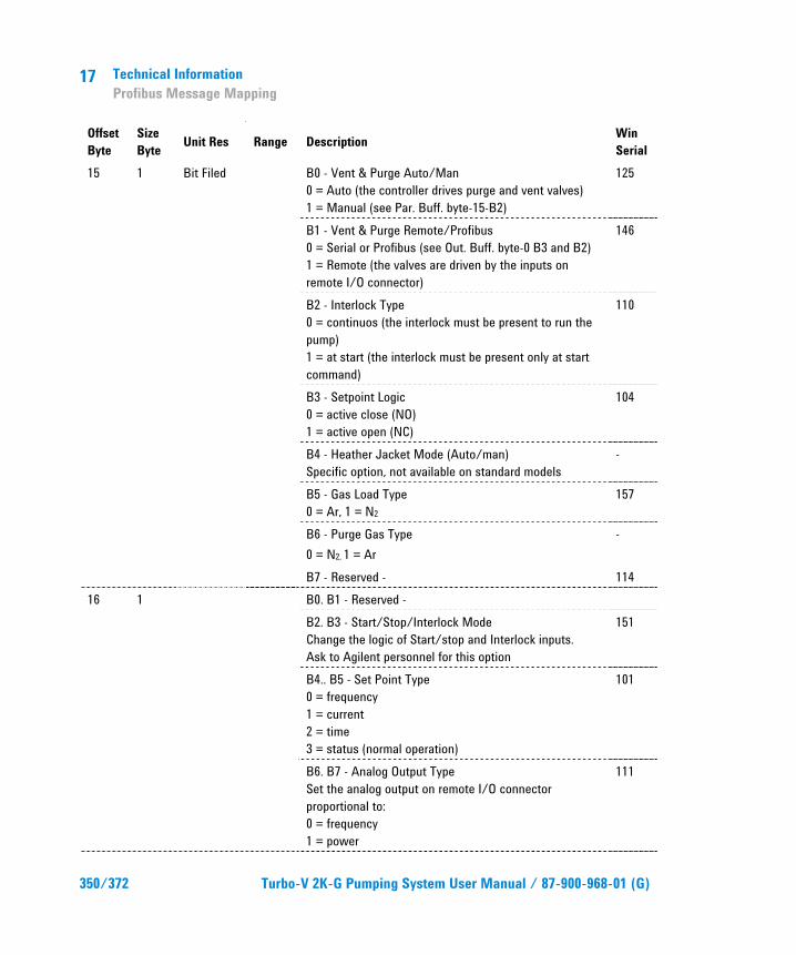
17 Technical Information Profibus Message Mapping
350/372 Turbo-V 2K-G Pumping System User Manual / 87-900-968-01 (G)
Offset Byte
Size Byte Unit Res Range Description Win
Serial 15 1 Bit Filed B0 - Vent & Purge Auto/Man
0 = Auto (the controller drives purge and vent valves) 1 = Manual (see Par. Buff. byte-15-B2)
125
B1 - Vent & Purge Remote/Profibus 0 = Serial or Profibus (see Out. Buff. byte-0 B3 and B2) 1 = Remote (the valves are driven by the inputs on remote I/O connector)
146
B2 - Interlock Type 0 = continuos (the interlock must be present to run the pump) 1 = at start (the interlock must be present only at start command)
110
B3 - Setpoint Logic 0 = active close (NO) 1 = active open (NC)
104
B4 - Heather Jacket Mode (Auto/man) Specific option, not available on standard models
-
B5 - Gas Load Type 0 = Ar, 1 = N2
157
B6 - Purge Gas Type 0 = N2, 1 = Ar
-
B7 - Reserved - 114 16 1 B0. B1 - Reserved - B2. B3 - Start/Stop/Interlock Mode
Change the logic of Start/stop and Interlock inputs. Ask to Agilent personnel for this option
151
B4.. B5 - Set Point Type 0 = frequency 1 = current 2 = time 3 = status (normal operation)
101
B6. B7 - Analog Output Type Set the analog output on remote I/O connector proportional to: 0 = frequency 1 = power
111
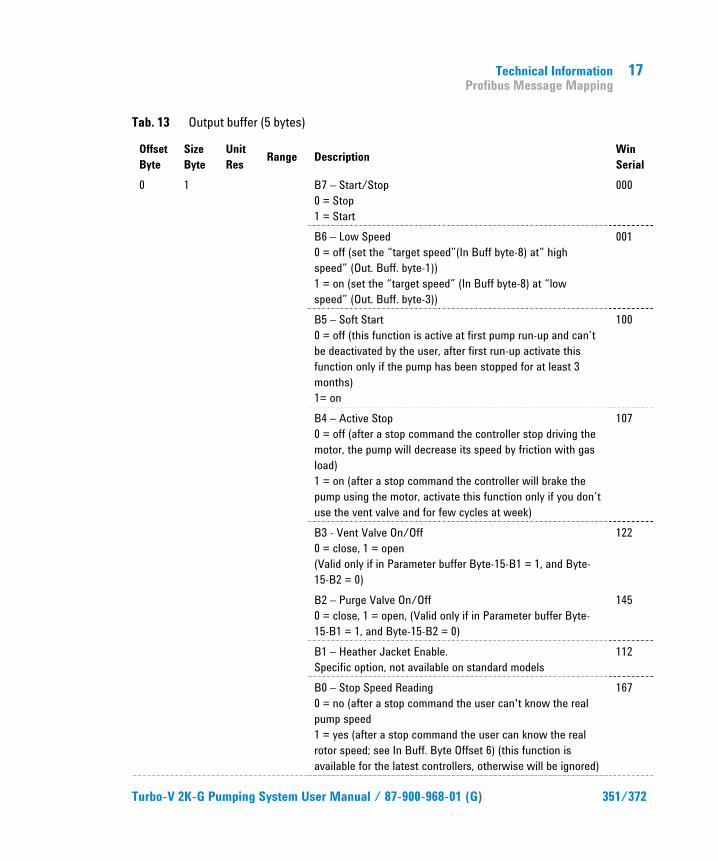
Technical Information Profibus Message Mapping
17
Turbo-V 2K-G Pumping System User Manual / 87-900-968-01 (G) 351/372
Tab. 13 Output buffer (5 bytes)
Offset Byte
Size Byte
Unit Res Range Description Win
Serial 0 1 B7 – Start/Stop
0 = Stop 1 = Start
000
B6 – Low Speed 0 = off (set the “target speed”(In Buff byte-8) at” high speed” (Out. Buff. byte-1)) 1 = on (set the “target speed” (In Buff byte-8) at “low speed” (Out. Buff. byte-3))
001
B5 – Soft Start 0 = off (this function is active at first pump run-up and can’t be deactivated by the user, after first run-up activate this function only if the pump has been stopped for at least 3 months) 1= on
100
B4 – Active Stop 0 = off (after a stop command the controller stop driving the motor, the pump will decrease its speed by friction with gas load) 1 = on (after a stop command the controller will brake the pump using the motor, activate this function only if you don’t use the vent valve and for few cycles at week)
107
B3 - Vent Valve On/Off 0 = close, 1 = open (Valid only if in Parameter buffer Byte-15-B1 = 1, and Byte-15-B2 = 0)
122
B2 – Purge Valve On/Off 0 = close, 1 = open, (Valid only if in Parameter buffer Byte-15-B1 = 1, and Byte-15-B2 = 0)
145
B1 – Heather Jacket Enable. Specific option, not available on standard models
112
B0 – Stop Speed Reading 0 = no (after a stop command the user can't know the real pump speed 1 = yes (after a stop command the user can know the real rotor speed; see In Buff. Byte Offset 6) (this function is available for the latest controllers, otherwise will be ignored)
167
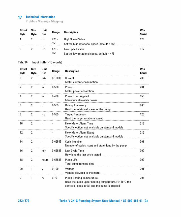
17 Technical Information Profibus Message Mapping
352/372 Turbo-V 2K-G Pumping System User Manual / 87-900-968-01 (G)
Offset Byte
Size Byte
Unit Res Range Description Win
Serial 1 2 Hz 475 -
555 High Speed Value Set the high rotational speed, default = 555
120
3 2 Hz 475 - 555
Low Speed Value Set the low rotational speed, default = 475
117
Tab. 14 Input buffer (15 words)
Offset Byte
Size Byte
Unit Res Range Description Win
Serial 0 2 mA 0-10000 Current
Motor current consumption 200
2 2 W 0-500 Power Motor power absorption
201
4 2 W 0-400 Power Limit Applied Maximum allowable power
155
6 2 Hz 0-555 Driving Frequency Read the rotational speed of the pump
203
8 2 Hz 0-555 Target Frequency Read the target rotational speed
120
10 2 - - Flow Meter Alarm Time Specific option, not available on standard models
213
12 2 - - Flow Meter Alarm Event Specific option, not available on standard models
215
14 2 - 0-65536 Cycle Number Number of cycles (start and stop) done by the pump
301
16 2 min 0-65536 Last Cycle Time How long the last cycle lasted
300
18 2 hours 0-65536 Pump Life Total pump running time
302
20 1 V 0-100 Voltage Voltage provided to the motor
201
21 1 °C 0-70 Pump Bearing Temperature Read the pump upper bearing temperature.If > 60°C the controller goes in fail and the pump is stopped
204
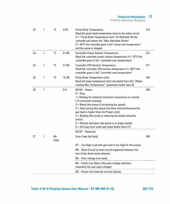
Technical Information Profibus Message Mapping
17
Turbo-V 2K-G Pumping System User Manual / 87-900-968-01 (G) 353/372
22 1 °C 0-45 Pump Body Temperature Read the pump body temperature close to the water circuit. If > “Pump Body Temperature Limit” (In Buff byte-25) the controller will reduce the "Max Allowable Power" If > 38°C the controller goes in fail “pump over-temperature” and the pump is stopped
216
23 1 °C 0-100 Controller Power Section Temperature Read the controller power section temperature if > 75°C the controller goes in fail “controller over-temperature”
222
24 1 °C 0-100 Controller CPU Section Temperature Read the controller CPU section temperature if > 80°C the controller goes in fail “controller over-temperature”
211
25 1 °C 15-38 Pump Body Temperature Limit Read the body temperature limit calculated from the” Water Cooling Max Temperature” (parameter buffer byte-0)
164
26 1 - 0-6 B0-B3 – Status 0 = Stop 1= Waiting for interlock (interlock connections on remote I/O connector missing) 2 = Ramp (the pump is increasing the speed) 3 = Auto tuning (the speed has been reduced because the gas load is higher than the Power Limit) 4 = Braking (the pump is reducing the speed using the motor) 5 = Normal operation (the pump is at target speed) 6 = Fail (see error code byte Input Buffer Byte-27)
205
B4-B7 – Reserved 27 1 Bit
Field Error Code (bit field) 206
B7 – Too High Load (the gas load is too high for the pump) B6 – Short Circuit (a short circuit happened between the two of the three motor phases)
B5 – Over-voltage (not used) B4 – Verify Line Select (the auto voltage selection mismatch the real input voltage)
B3 – Power Fail (internal circuitry failure)
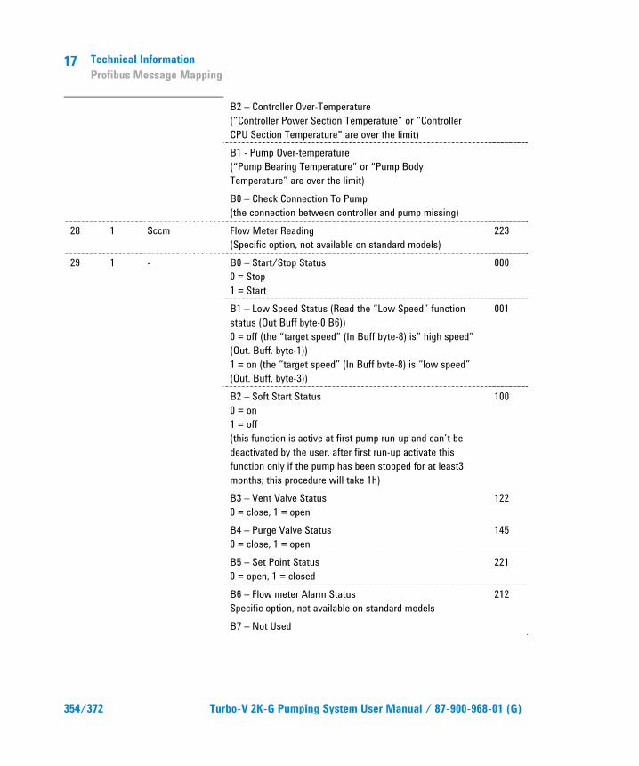
17 Technical Information Profibus Message Mapping
354/372 Turbo-V 2K-G Pumping System User Manual / 87-900-968-01 (G)
B2 – Controller Over-Temperature (“Controller Power Section Temperature” or “Controller CPU Section Temperature" are over the limit)
B1 - Pump Over-temperature (“Pump Bearing Temperature” or “Pump Body Temperature” are over the limit)
B0 – Check Connection To Pump (the connection between controller and pump missing)
28 1 Sccm Flow Meter Reading (Specific option, not available on standard models)
223
29 1 - B0 – Start/Stop Status 0 = Stop 1 = Start
000
B1 – Low Speed Status (Read the “Low Speed” function status (Out Buff byte-0 B6)) 0 = off (the “target speed” (In Buff byte-8) is” high speed” (Out. Buff. byte-1)) 1 = on (the “target speed” (In Buff byte-8) is “low speed” (Out. Buff. byte-3))
001
B2 – Soft Start Status 0 = on 1 = off (this function is active at first pump run-up and can’t be deactivated by the user, after first run-up activate this function only if the pump has been stopped for at least3 months; this procedure will take 1h)
100
B3 – Vent Valve Status 0 = close, 1 = open
122
B4 – Purge Valve Status 0 = close, 1 = open
145
B5 – Set Point Status 0 = open, 1 = closed
221
B6 – Flow meter Alarm Status Specific option, not available on standard models
212
B7 – Not Used
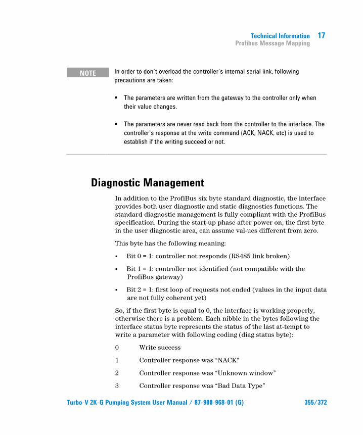
Technical Information Profibus Message Mapping
17
Turbo-V 2K-G Pumping System User Manual / 87-900-968-01 (G) 355/372
NOTE In order to don’t overload the controller’s internal serial link, following precautions are taken:
� The parameters are written from the gateway to the controller only when their value changes.
� The parameters are never read back from the controller to the interface. The controller’s response at the write command (ACK, NACK, etc) is used to establish if the writing succeed or not.
Diagnostic Management In addition to the ProfiBus six byte standard diagnostic, the interface provides both user diagnostic and static diagnostics functions. The standard diagnostic management is fully compliant with the ProfiBus specification. During the start-up phase after power on, the first byte in the user diagnostic area, can assume val-ues different from zero.
This byte has the following meaning:
� Bit 0 = 1: controller not responds (RS485 link broken)
� Bit 1 = 1: controller not identified (not compatible with the ProfiBus gateway)
� Bit 2 = 1: first loop of requests not ended (values in the input data are not fully coherent yet)
So, if the first byte is equal to 0, the interface is working properly, otherwise there is a problem. Each nibble in the bytes following the interface status byte represents the status of the last at-tempt to write a parameter with following coding (diag status byte):
0 Write success
1 Controller response was “NACK”
2 Controller response was “Unknown window”
3 Controller response was “Bad Data Type”

17 Technical Information Profibus Message Mapping
356/372 Turbo-V 2K-G Pumping System User Manual / 87-900-968-01 (G)
4 Controller response was “Over range”
5 Controller response was “Bad operation”
6 Controller response was an unknown response
F Parameter not supported by the controller
The ProfiBus external diagnosis services are used to report following unexpected situations:
� Controller fail: if the controller goes in fail mode, an external diagnostic service is re-quired and one byte in the diagnostic buffer signals the type of failure.
� User parameter mismatch: if the user sets one or more parameters out of their allowed range, a ProfiBus external diagnostic service is required and some bits in the diagnosis frame signals which parameter is wrong (i.e. over range or under range).
Diagnostic Buffer Tab. 15 Diagnostic buffer
Offset Meaning 0 B0 station non exist (set by master)
B1 station not ready (slave not ready for data exchange) B2 cfg fault (configuration data doesn’t match) B3 ext diag (slave has external diagnostic data) B4 not supported (slave doesn’t support requested function) B5 invalid slave response ( slave sets permanent ‘0’) B6 prm fault (wrong parameter assignment) B7 master_lock (slave is parameterised by another master)
Stan
dard
diag
nost
ic
1 B0 prm req (slave has to be re-parameterised) B1 stat diag (static diagnosis) B2 fixed ‘1’ B3 wd_on (response monitoring active) B4 Freeze mode (received freeze command) B5 Synch mode (received synch command) B6 reserved B7 diag deactivated (slave is parameterised by another master)
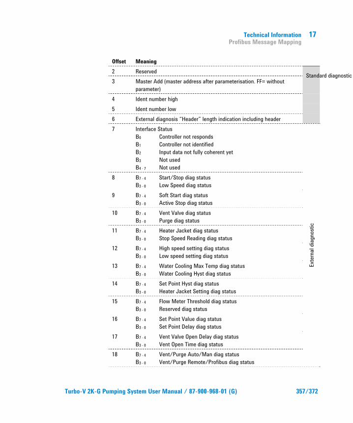
Technical Information Profibus Message Mapping
17
Turbo-V 2K-G Pumping System User Manual / 87-900-968-01 (G) 357/372
Offset Meaning 2 Reserved 3 Master Add (master address after parameterisation. FF= without
parameter) 4 Ident number high 5 Ident number low 6 External diagnosis “Header” length indication including header 7 Interface Status
B0 Controller not responds B1 Controller not identified B2 Input data not fully coherent yet B3 Not used B4 - 7 Not used
Exte
rnal
diagn
ostic
8 B7 - 4 Start/Stop diag status B3 - 0 Low Speed diag status
9 B7 - 4 Soft Start diag status B3 - 0 Active Stop diag status
10 B7 - 4 Vent Valve diag status B3 - 0 Purge diag status
11 B7 - 4 Heater Jacket diag status B3 - 0 Stop Speed Reading diag status
12 B7 - 4 High speed setting diag status B3 - 0 Low speed setting diag status
13 B7 - 4 Water Cooling Max Temp diag status B3 - 0 Water Cooling Hyst diag status
14 B7 - 4 Set Point Hyst diag status B3 - 0 Heater Jacket Setting diag status
15 B7 - 4 Flow Meter Threshold diag status B3 - 0 Reserved diag status
16 B7 - 4 Set Point Value diag status B3 - 0 Set Point Delay diag status
17 B7 - 4 Vent Valve Open Delay diag status B3 - 0 Vent Open Time diag status
18 B7 - 4 Vent/Purge Auto/Man diag status B3 - 0 Vent/Purge Remote/Profibus diag status
Standard diagnostic
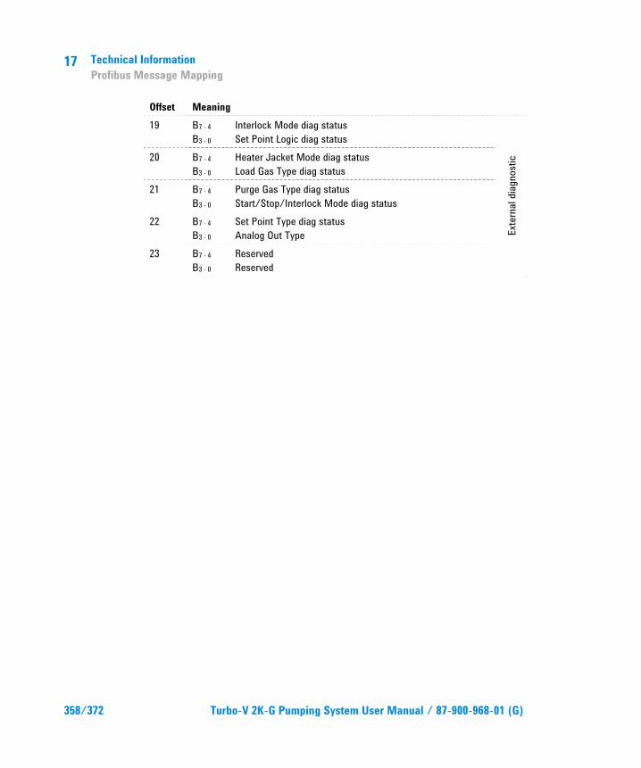
17 Technical Information Profibus Message Mapping
358/372 Turbo-V 2K-G Pumping System User Manual / 87-900-968-01 (G)
Offset Meaning 19 B7 - 4 Interlock Mode diag status
B3 - 0 Set Point Logic diag status
Exte
rnal
diagn
ostic
20 B7 - 4 Heater Jacket Mode diag status B3 - 0 Load Gas Type diag status
21 B7 - 4 Purge Gas Type diag status B3 - 0 Start/Stop/Interlock Mode diag status
22 B7 - 4 Set Point Type diag status B3 - 0 Analog Out Type
23 B7 - 4 Reserved B3 - 0 Reserved

Technical Information Inlet Screen Installation
17
Turbo-V 2K-G Pumping System User Manual / 87-900-968-01 (G) 359/372
Inlet Screen Installation
Figure 43
The inlet screen mod. 969-9138 prevents the blades of the pump from being damaged by debris greater than 5.2 mm diameter.
The inlet screen, however, does reduce the pumping speed by about 10%.
The inlet screen is fitted in the upper part of the pump, as shown in the figure.
It is welded to the center ring of the ISO 250 F viton gasket.
Figure 44
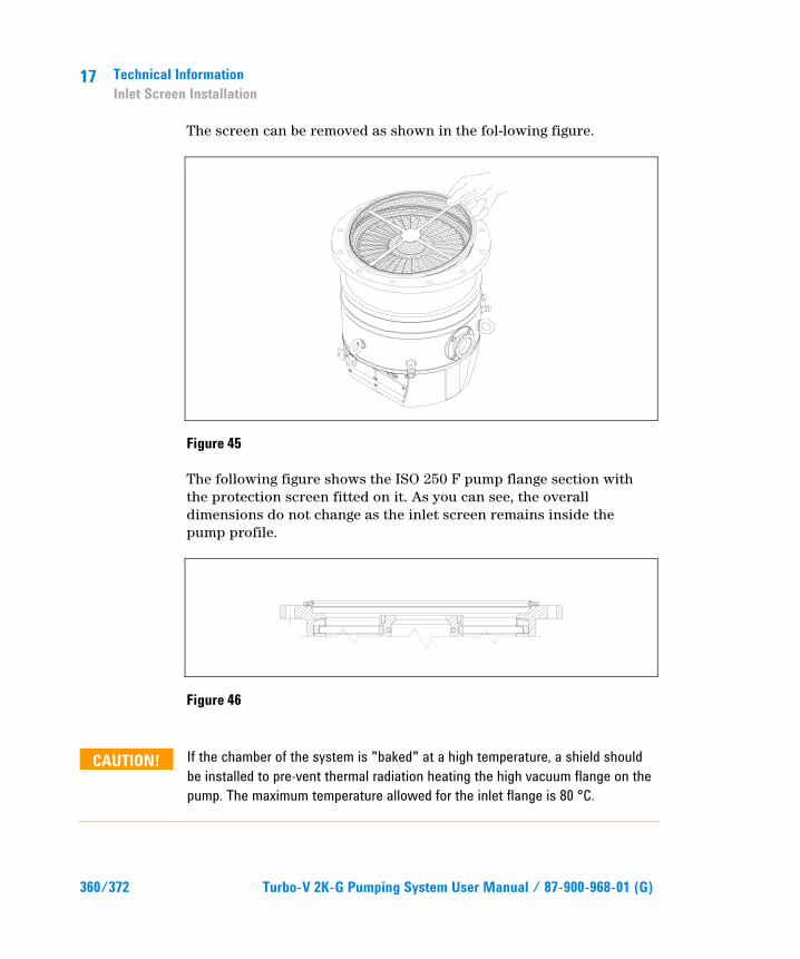
17 Technical Information Inlet Screen Installation
360/372 Turbo-V 2K-G Pumping System User Manual / 87-900-968-01 (G)
The screen can be removed as shown in the fol-lowing figure.
Figure 45
The following figure shows the ISO 250 F pump flange section with the protection screen fitted on it. As you can see, the overall dimensions do not change as the inlet screen remains inside the pump profile.
Figure 46
CAUTION! If the chamber of the system is "baked" at a high temperature, a shield should be installed to pre-vent thermal radiation heating the high vacuum flange on the pump. The maximum temperature allowed for the inlet flange is 80 °C.

Technical Information Water Cooling Connection
17
Turbo-V 2K-G Pumping System User Manual / 87-900-968-01 (G) 361/372
Water Cooling Connection The pumping system is supplied with a metallic model water cooling kit.
Figure 47
Two 9 – 10 mm internal diameter rubber or plastic tubes from the water supply must be fitted to the two dedicated nozzles.
NOTE These tubes must be held on the respective nozzles using hose clips to avoid that the tube(s) gets loose or disconnected during operation.
Cooling may be carried out either through an open circuit with eventual discharge of the water, or using a closed circuit cooling system.
The water temperature must be between +10 °C and +35 °C, with an inlet pressure between 3 and 5 bar. In any case the water flow must not be less than 200 l/h.
The customer can alternatively order the 90 °C bend water cooling kit, plastic model (969-9348) or me-tallic model (969-9338).
NOTE The water electrical conductance must be � 500 µs/cm. When the conductance is higher, in closed water circuit, the use of up to 20 % of Ethyl-Glycole is suggested.

17 Technical Information Pump Purging and Venting
362/372 Turbo-V 2K-G Pumping System User Manual / 87-900-968-01 (G)
Pump Purging and Venting The Turbo-V 2K-G pump is equipped with an integrated purging and venting valve device. Both valves are fed through a single gas port, with 1/8 NPT thread or Swagelok connector.
Purge and Vent Installation To install the gas purge and vent line it is necessary to unscrew the purge/vent port cover, and then connect the gas line.
Pump Used With Corrosive Gases To prevent damage to the bearings, an inert gas must flow into the pump body around the upper bearing towards the forevacuum line. To supply the inert purge gas (e. g. nitrogen) to the pump through the purge port, connect a gas purge line to the pump.
The purging device automatically provides 20 sccm when fed with 1 bar (14 psi) absolute (at-mospheric pressure).
CAUTION! To prevent bearing damage, Agilent suggests a minimum purge gas flow rate of 20 sccm (0.33 mbar l/s). This value can be exceeded, according to the process requirements. Please contact Agilent for specific applications.
The purge gas throughput of 20 sccm with the rec-ommended forepump allows to achieve a high vacuum pressure in the 10-6 mbar range.
The recommended gas flow maintains a pressure into the pump body higher than the forevacuum pressure.
The recommended procedure to vent the system and the pump avoiding the contact between the pump bearings and the corrosive gas is described in the following points:

Technical Information Pump Purging and Venting
17
Turbo-V 2K-G Pumping System User Manual / 87-900-968-01 (G) 363/372
1 Close the corrosive gas flow into the system.
2 Leaving the Turbo-V 2K-G pump and the backing pump running and the purge gas flowing, wait for enough time to evacuate the corrosive gas from the system.
3 Turn off the Turbopump.
4 Open the Turbo-V 2K-G vent electro valve up to the atmospheric pressure in the system.
5 When the Turbo-V 2K-G pump and the backing pump are stopped and the system is at atmospheric pressure, for a better bearing protection it is advisable to leave the purge gas flowing into the Turbo-V pump, with the chamber or the Turbo-V vent valve opened, to avoid system overpressures. If the vent valve can’t be kept opened, the backing pump should be left operating.
Figure 48 Purge and vent layout
VACUUM TECHNOLOGIES
1 Purge gas line 2 Pressure regulator 3 Purge and vent port 4 Forevacuum pump 5 Turbopump 6 Water line

17 Technical Information High Vacuum Flange Connection
364/372 Turbo-V 2K-G Pumping System User Manual / 87-900-968-01 (G)
High Vacuum Flange Connection To connect the Turbo-V 2K-G pump to the ISO F inlet flange position the integrated inlet screen - centering ring as shown in the figure.
Figure 49
Then fix the two flanges with the bolts as shown in the following figures. (according to Norm ISO 1609)
Figure 50
Figure 51
Technical Information Fore-Vacuum Pump Connection
17
Turbo-V 2K-G Pumping System User Manual / 87-900-968-01 (G) 365/372
Fore-Vacuum Pump Connection A flange KF 40 NW is available to connect the Turbo V2K-G pump to the fore-vacuum pump. A hose or vacuum approved pipe can be used. If a rigid pipe is used, any vibration generated by the mechanical pump must be eliminated through the use of bellows.
NOTE The Turbo-V 2K-G pump is characterized by its high compression ratio also for oil vapors. When using a mechanical oil-sealed pump, it is advisable to install a suitable trap between the turbopump and the fore-vacuum pump in order to prevent oil backstreaming.
Pump Used in Presence of Magnetic Fields Magnetic fields induce eddy currents in the rotor of a turbomolecular pump that tend to oppose to its rotation.
The result is increased electrical power consumption by the motor, most of which is dissipated in the rotor.
Since the rotor is not in contact with the stator the above power can leave the rotor mainly by radiation and hence the rotor may be overheated while static parts of the pump remain cool.
This effect is strongly dependant from the intensity, time function and distribution of the magnetic field.
In general, therefore, an increase in pump current can be expected.
If this increase is lower than 50 % of the current value drawn by the motor in high vacuum operation, no particular problem should be expected.
However if the effect is greater, than the case should be carefully reviewed by Agilent’s specialist. As a matter of fact, in case of high magnetic fields, also important forces might be generated and applied to the rotor.
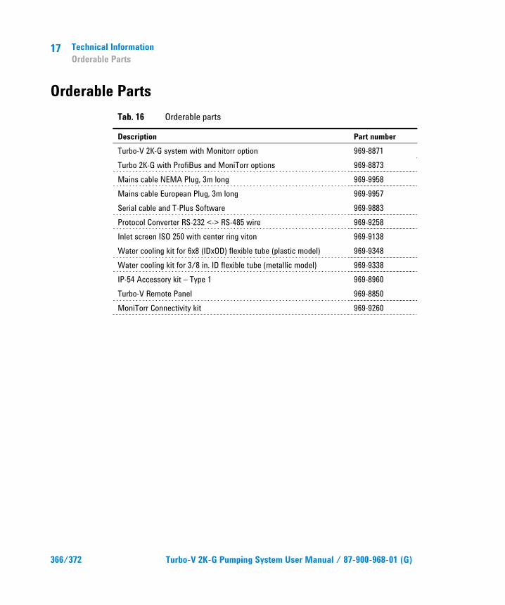
17 Technical Information Orderable Parts
366/372 Turbo-V 2K-G Pumping System User Manual / 87-900-968-01 (G)
Orderable Parts Tab. 16 Orderable parts
Description Part number Turbo-V 2K-G system with Monitorr option 969-8871 Turbo 2K-G with ProfiBus and MoniTorr options 969-8873 Mains cable NEMA Plug, 3m long 969-9958 Mains cable European Plug, 3m long 969-9957 Serial cable and T-Plus Software 969-9883 Protocol Converter RS-232 <-> RS-485 wire 969-9258 Inlet screen ISO 250 with center ring viton 969-9138 Water cooling kit for 6x8 (IDxOD) flexible tube (plastic model) 969-9348 Water cooling kit for 3/8 in. ID flexible tube (metallic model) 969-9338 IP-54 Accessory kit – Type 1 969-8960 Turbo-V Remote Panel 969-8850 MoniTorr Connectivity kit 969-9260
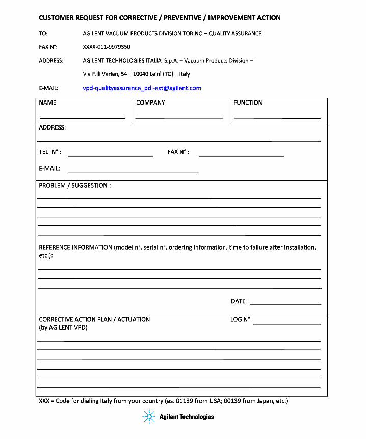
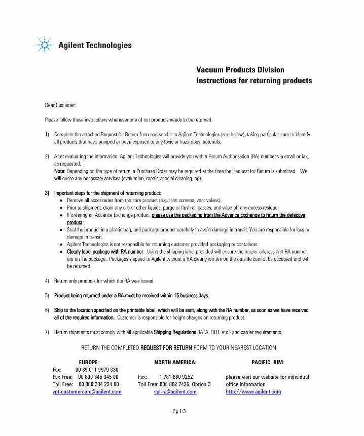


Request for Return Form Sales and Service Offices
United States Agilent Technologies Vacuum Products Division 121 Hartwell Avenue Lexington, MA 02421 - USA Tel.: +1 781 861 7200 Fax: +1 781 860 5437 Toll-Free: +1 800 882 7426
India Agilent Technologies India Pvt. Ltd. Vacuum Product Division G01. Prime corporate Park, 230/231, Sahar Road, Opp. Blue Dart Centre, Andheri (East), Mumbai – 400 099.India Tel: +91 22 30648287/8200 Fax: +91 22 30648250 Toll Free: 1800 113037
Southeast Asia Agilent Technologies Sales Sdn Bhd Vacuum Products Division Unit 201, Level 2 uptown 2, 2 Jalan SS21/37, Damansara Uptown 47400 Petaling Jaya, Selangor, Malaysia Tel : +603 7712 6106 Fax: +603 6733 8121
Benelux Agilent Technologies Netherlands B.V. Vacuum Products Division Herculesweg 8 4338 PL Middelburg The Netherlands Tel.: +31 118 671570 Fax: +31 118 671569 Toll-Free: 00 800 234 234 00
Italy Agilent Technologies Italia S.p.A. Vacuum Products Division Via F.lli Varian, 54 10040 Leinì, (Torino) - Italy Tel.: +39 011 997 9111 Fax: +39 011 997 9350 Toll-Free: 00 800 234 234 00
Taiwan Agilent Technologies Taiwan Limited Vacuum Products Division (3F) 20 Kao-Shuang Rd., Pin-Chen City, 324 Taoyuan Hsien , Taiwan, R.O.C. Tel. +886 34959281 Toll Free: 0800 051 342
Canada Central coordination through: Agilent Technologies Vacuum Products Division 121 Hartwell Avenue Lexington, MA 02421 - USA Tel.: +1 781 861 7200 Fax: +1 781 860 5437 Toll-Free: +1 800 882 7426
Japan Agilent Technologies Japan, Ltd. Vacuum Products Division 8th Floor Sumitomo Shibaura Building 4-16-36 Shibaura Minato-ku Tokyo 108-0023 - Japan Tel.: +81 3 5232 1253 Fax: +81 3 5232 1710 Toll-Free: 0120 655 040
UK and Ireland Agilent Technologies UK, Ltd. Vacuum Products Division 6 Mead Road Oxford Industrial Park Yarnton, Oxford OX5 1QU – UK Tel.: +44 (0) 1865 291570 Fax: +44 (0) 1865 291571 Toll free: 00 800 234 234 00
China Agilent Technologies (China) Co. Ltd Vacuum Products Division No.3, Wang Jing Bei Lu, Chao Yang District, Beijing, 100102 China Tel.: +86 (10) 6439 7718 Toll-Free: 800 820 6556
Korea Agilent Technologies Korea, Ltd. Vacuum Products Division Shinsa 2nd Bldg. 2F 966-5 Daechi-dong Kangnam-gu, Seoul Korea 135-280 Tel.: +82 2 3452 2452 Fax: +82 2 3452 2451 Toll-Free: 080 222 2452
Other Countries Agilent Technologies Italia S.p.A. Vacuum Products Division Via F.lli Varian, 54 10040 Leinì, (Torino) - Italy Tel.: +39 011 997 9111 Fax: +39 011 997 9350 Toll-Free: 00 800 234 234 00
France Agilent Technologies France Vacuum Products Division 7 Avenue des Tropiques Z.A. de Courtaboeuf - B.P. 12 91941 Les Ulis cedex - France Tel.: +33 (0) 1 69 86 38 84 Fax: +33 (0) 1 69 86 29 88 Toll free: 00 800 234 234 00
Mexico Agilent Technologies Vacuum Products Division Concepcion Beistegui No 109 Col Del Valle C.P. 03100 – Mexico, D.F. Tel.: +52 5 523 9465 Fax: +52 5 523 9472
Customer Support & Service NORTH AMERICA: Toll Free: 800 882 7426, Option 3 [email protected] EUROPE: Toll Free: 00 800 234 234 00 [email protected] PACIFIC RIM: please visit our website for individual office information http://www.agilent.com Worldwide Web Site, Catalog and Order On-line: www.agilent.com Representative in most countries 12/10
Germany and Austria Agilent Technologies Vacuum Products Division Alsfelder Strasse 6 Postfach 11 14 35 64289 Darmstadt – Germany Tel.: +49 (0) 6151 703 353 Fax: +49 (0) 6151 703 302 Toll free: 00 800 234 234 00
Singapore Agilent Technologies Singapore Pte. Ltd, Vacuum Products Division Agilent Technologies Building, 1 Yishun Avenue 7, Singapore 768923 Tel : (65) 6215 8045 Fax : (65) 6754 0574
© Agilent Technologies, Inc. 2011 Printed in ITALY 04/2011 Publication Number: 87-900-968-01 (G)