turbo machinesturbo machines - kopykitab€¦ · turbo machinesturbo machines ... application of...
TRANSCRIPT

2
TURBO MACHINESTURBO MACHINESTURBO MACHINESTURBO MACHINES
VTU Syllabus
Subject Code : 06ME55 IA Marks : 25
No. of Lecture Hrs./Week : 04 Exam Hours : 03
Total No.of Lecture Hrs. : 52 Exam Marks : 100
PART – A
UNIT – 1
INTRODUCTION: Definition of a Turbomachine; parts of a Turbomachine; Comparison with positive
displacement machine; Classification: Application of First and Second Laws to Turbomachines, Efficiencies.
Dimensionless parameters and their physical significance; Effect of Reynolds number; Specific speed; Illustrative
examples on dimensional analysis and model studies. 6 Hours
UNIT – 2
ENERGY TRANSFER IN TURBO MACHINE: Euler Turbine equation; Alternate form of Euler
turbine equation – components of energy transfer; Degree of reaction; General analysis of a Turbo machine – effect
of blade discharge angle on energy transfer and degree of reaction; General analysis of centrifugal pumps and
compressors – Effect of blade discharge angle on performance; Theoretical head – capacity relationship
6 Hours
UNIT – 3
GENERAL ANALYSIS OF TURBO MACHINES: Axial flow compressors and pumps – general
expression for degree of reaction; velocity triangles for different values of degree of reaction; General analysis of axial
and radial flow turbines – Utilization factor; Vane efficiency; Relation between utilization factor and degree of reaction;
condition for maximum utilization factor – optimum blade speed ratio for different types of turbines 7 Hours
UNIT – 4
THERMODYNAMICS OF FLUID FLOW AND THERMODYNAMIC ANALYSIS
OF COMPRESSION AND EXPANSION PROCESSES: Sonic velocity and Mach number;
Classification of fluid flow based on Mach number; Stagnation and static properties and their relations; Compression
process – Overall isentropic efficiency of compression; Stage efficiency; Comparison and relation between overall
efficiency and stage efficiency; Polytrophic efficiency; Preheat factor, Expansion Process – Overall isentropic
efficiency for a turbine; Stage efficiency for a turbine; Comparison and relation between stage efficiency and overall
efficiency for expansion process, polytrophic efficiency of expansion; Reheat factor for expansion process.
7 Hours

3
PART – B
UNIT – 5
CENTRIFUGAL COMPRESSORS: Classification; Expression for overall pressure ratio developed;
Blade angles at impeller eye root and eye tip; Slip factor and power input factor; width of the impeller channel;
Compressibility effect – need for pre-whirl vanes; Diffuser design: Flow in the vaneless space, determination of
diffuser inlet vane angle, width and length of the diffuser passages; Surging of centrifugal compressors;
AXIAL FLOW COMPRESSORS: Classification; Expression for Pressure ratio developed per stage –
work done factor, radial equilibrium conditions. 6 Hours
UNIT – 6
CENTRIFUGAL PUMPS: Definition of terms used in the design of centrifugal pumps like manometric
head, suction head, delivery head, pressure rise, manometric efficiency, hydraulic efficiency, volumetric efficiency,
overall efficiency, multistage centrifugal pumps, minimum starting speed, slip, priming, cavitation, NPSH.
6 Hours
UNIT – 7
STEAM TURBINES: Classification, Single stage impulse turbine; Condition for maximum blade efficiency,
stage efficiency, Compounding – Need for compounding, method of compounding. Impulse Staging – Condition of
maximum utilization factor for multi stage turbine with equiangular blades; effect of blades and nozzle losses.
Reaction turbine; Parson’s reaction turbine, condition for maximum blade efficiency, reaction staging. 7 Hours
UNIT – 8
HYDRAULIC TURBINES: Classification; Pelton Turbine-velocity triangles, Design parameters, turbine
efficiency, volumetric efficiency; Francis turbine – velocity triangles, runner shapes for different blade speeds, Design
of Francis turbine; Function of a Draft tube, types of draft tubes; Kaplan and Propeller turbines – Velocity triangles
and design parameters. 7 Hours
TEXT BOOKS: 1. An Introduction to energy conversion, Volume III – Turbo machinery, V. Kadambi and Manohar Prasad,
New Age International Publishers (P) Ltd.
2. “Turbines, Compressors & Fans”, S.M. Yahya, Tata-McGraw Hill Co., 2nd
Edition (2002).
REFERENCE BOOKS: 1. “Principles of Turbo Machinery”, D.G. Shepherd, The Macmillan Company (1964).
2. Fundamentals of Turbomachinery: William W. Perg, John Wiley & Sons, Inc. 2008.
3. A Text book of Turbo Machines - M.S.Govindgouda & A.M. Nagaraj-M.M.Publications-IV Edition-2008
4. “Fluid Machinery” B.K. Venkanna, PHI.
4
� In these lectures, we will learn different type of turbo machines, their action,
as power generating turbo machines or power absorbing turbo machines.
� You will be shown schematic diagrams of various turbo machines with flow
directions.
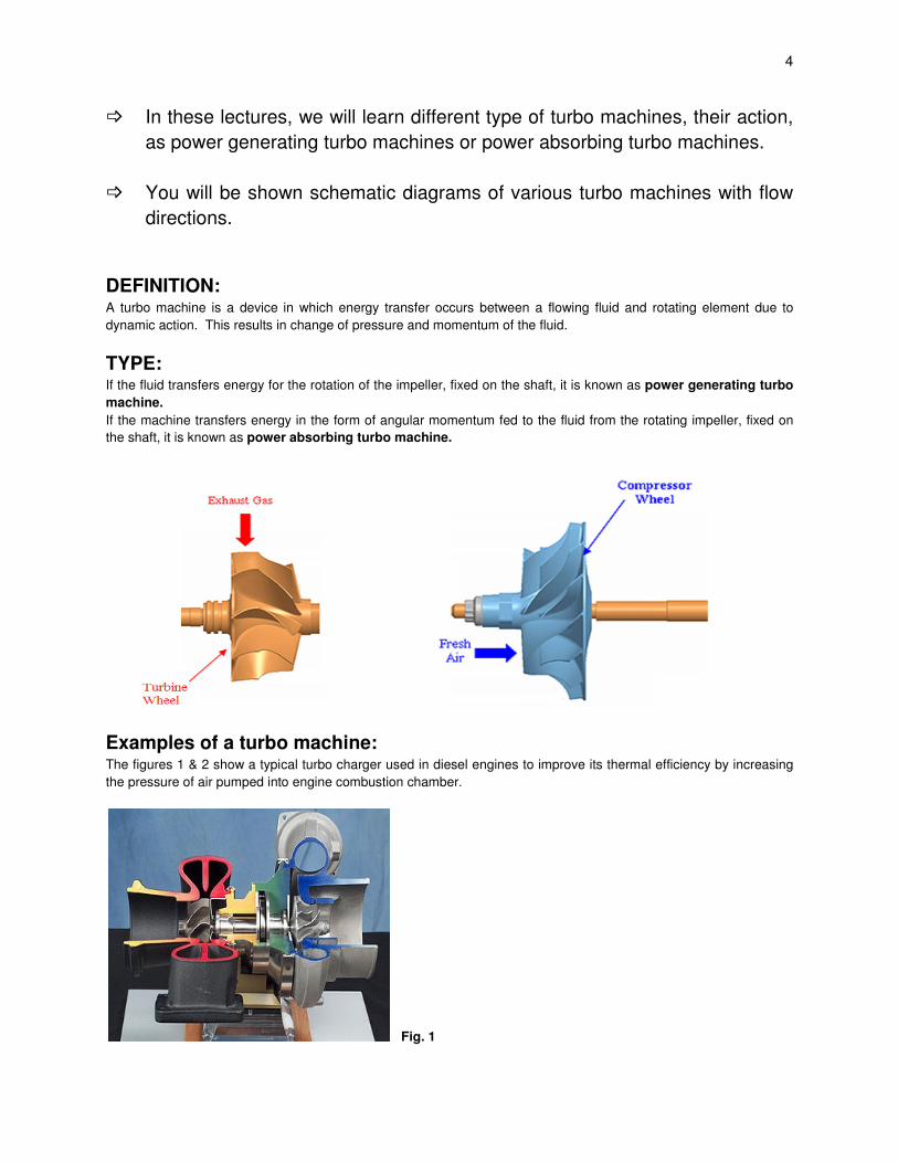
DEFINITION: A turbo machine is a device in which energy transfer occurs between a flowing fluid and rotating element due to
dynamic action. This results in change of pressure and momentum of the fluid.
TYPE: If the fluid transfers energy for the rotation of the impeller, fixed on the shaft, it is known as power generating turbo
machine.
If the machine transfers energy in the form of angular momentum fed to the fluid from the rotating impeller, fixed on
the shaft, it is known as power absorbing turbo machine.
Examples of a turbo machine: The figures 1 & 2 show a typical turbo charger used in diesel engines to improve its thermal efficiency by increasing
the pressure of air pumped into engine combustion chamber.
Fig. 1
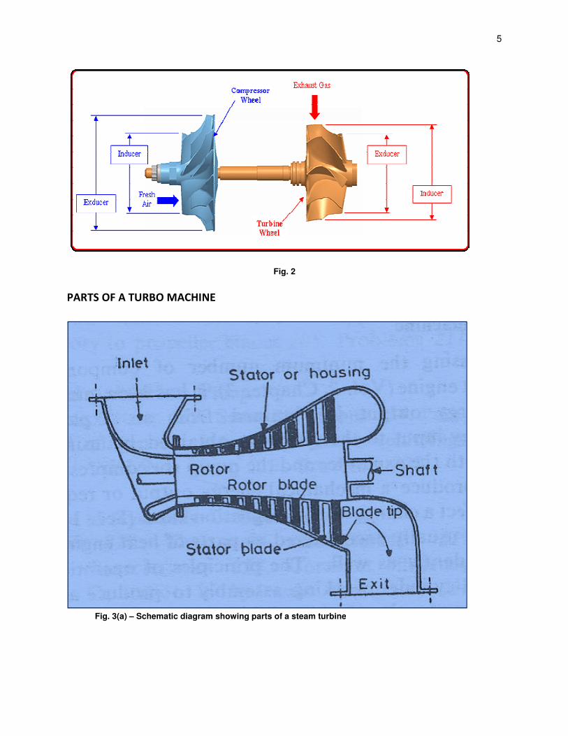
PARTS OF A TURBO MACHINE
Fig. 3(a) – Schematic diagram showing parts of a steam turbine
Fig. 2
PARTS OF A TURBO MACHINE
diagram showing parts of a steam turbine
5
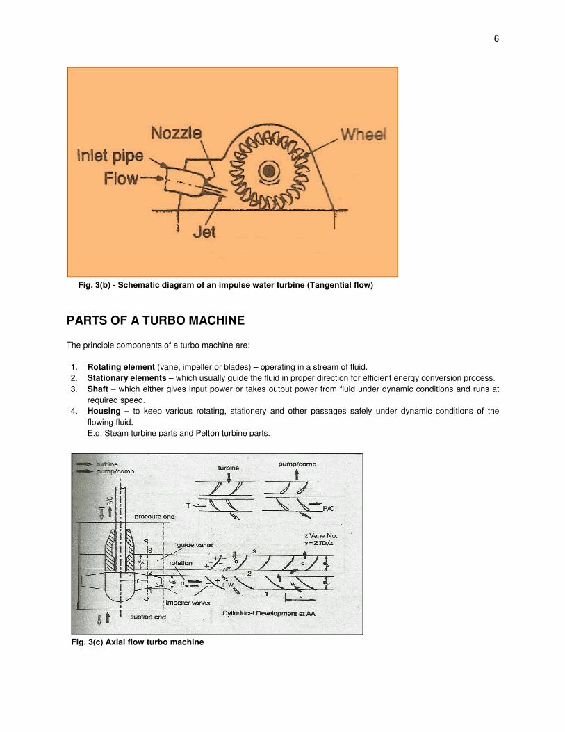
Fig. 3(b) - Schematic diagram of an impulse water turbine (Tangential flow)
PARTS OF A TURBO MACHINE
The principle components of a turbo machine are:
1. Rotating element (vane, impeller or blades)
2. Stationary elements – which usually guide the fluid in proper direction for efficient energy conversion process.
3. Shaft – which either gives input power or takes output power from fluid under dyn
required speed.
4. Housing – to keep various rotating, stationery and other passages safely under dynamic conditions of the
flowing fluid.
E.g. Steam turbine parts and Pelton turbine parts.
Fig. 3(c) Axial flow turbo machine
Schematic diagram of an impulse water turbine (Tangential flow)
PARTS OF A TURBO MACHINE
The principle components of a turbo machine are:
(vane, impeller or blades) – operating in a stream of fluid.
which usually guide the fluid in proper direction for efficient energy conversion process.
which either gives input power or takes output power from fluid under dynamic conditions and runs at
to keep various rotating, stationery and other passages safely under dynamic conditions of the
E.g. Steam turbine parts and Pelton turbine parts.
6
which usually guide the fluid in proper direction for efficient energy conversion process.
amic conditions and runs at
to keep various rotating, stationery and other passages safely under dynamic conditions of the

7
Fig. 3(d) Radial flow turbo machine
CLASSIFICATION OF TURBO MACHINES
1. Based on energy transfer
a) Energy is given by fluid to the rotor - Power generating turbo machine E.g. Turbines
b) Energy given by the rotor to the fluid – Power absorbing turbo machine
c) E.g. Pumps, blowers and compressors
2. Based on fluid flowing in turbo machine
a) Water
b) Air
c) Steam
d) Hot gases
e) Liquids like petrol etc.
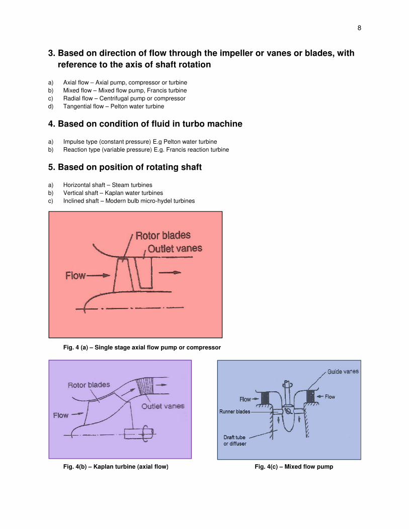
3. Based on direction of flow through the impeller or vanes or blades, with
reference to the axis of shaft rotation
a) Axial flow – Axial pump, compressor or turbine
b) Mixed flow – Mixed flow pump, Francis turbine
c) Radial flow – Centrifugal pump or compressor
d) Tangential flow – Pelton water turbine
4. Based on condition of fluid in turbo machine
a) Impulse type (constant pressure) E.g Pelton water turbine
b) Reaction type (variable pressure) E.g. Francis reaction turbine
5. Based on position of rotating shaft
a) Horizontal shaft – Steam turbines
b) Vertical shaft – Kaplan water turbines
c) Inclined shaft – Modern bulb micro
Fig. 4 (a) – Single stage axial flow pump or compressor
Fig. 4(b) – Kaplan turbine (axial flow)
Based on direction of flow through the impeller or vanes or blades, with
reference to the axis of shaft rotation
Axial pump, compressor or turbine
Mixed flow pump, Francis turbine
Centrifugal pump or compressor
Pelton water turbine
4. Based on condition of fluid in turbo machine
Impulse type (constant pressure) E.g Pelton water turbine
Reaction type (variable pressure) E.g. Francis reaction turbine
5. Based on position of rotating shaft
Kaplan water turbines
Modern bulb micro-hydel turbines
Single stage axial flow pump or compressor
Kaplan turbine (axial flow) Fig. 4(c) – Mixed flow pump
8
Based on direction of flow through the impeller or vanes or blades, with
Mixed flow pump
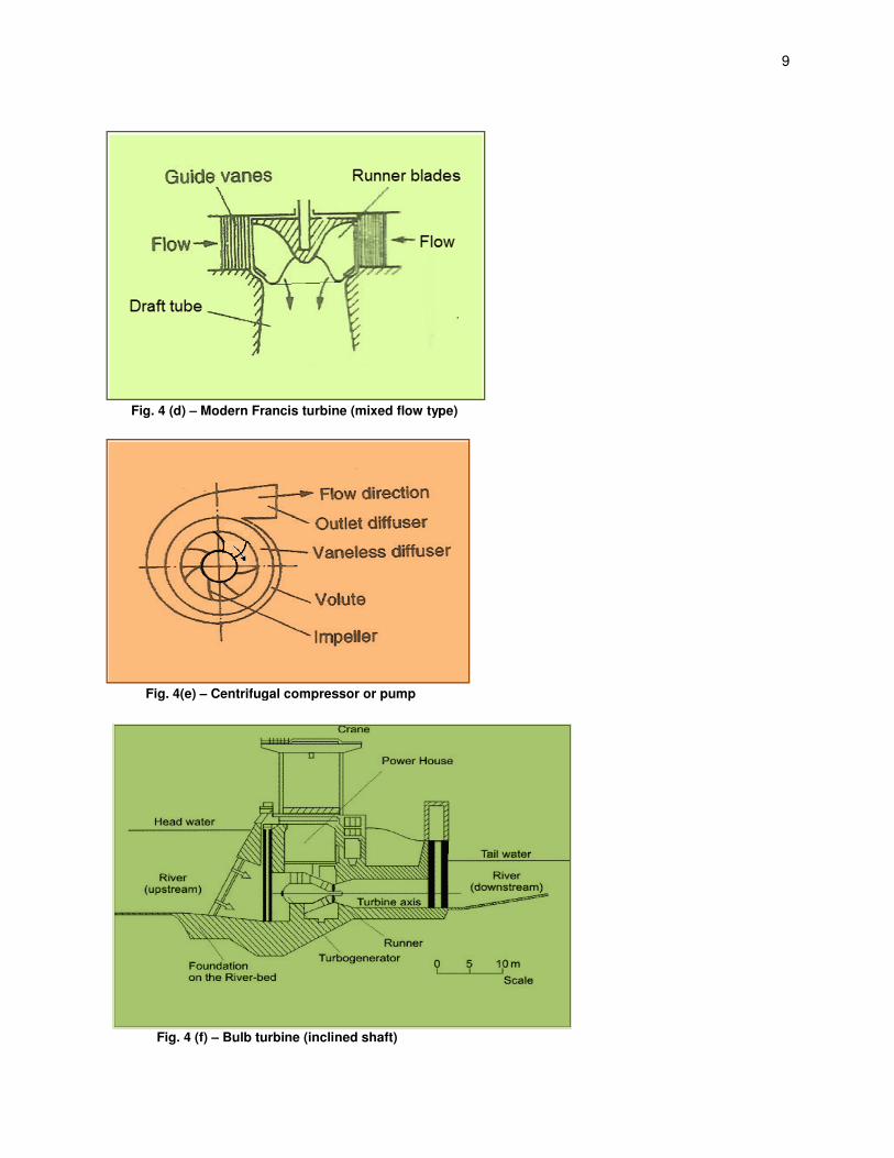
Fig. 4 (d) – Modern Francis turbine (mixed flow type)
Fig. 4(e) – Centrifugal compressor
Fig. 4 (f) – Bulb turbine (inclined shaft)
Modern Francis turbine (mixed flow type)
Centrifugal compressor or pump
Bulb turbine (inclined shaft)
9
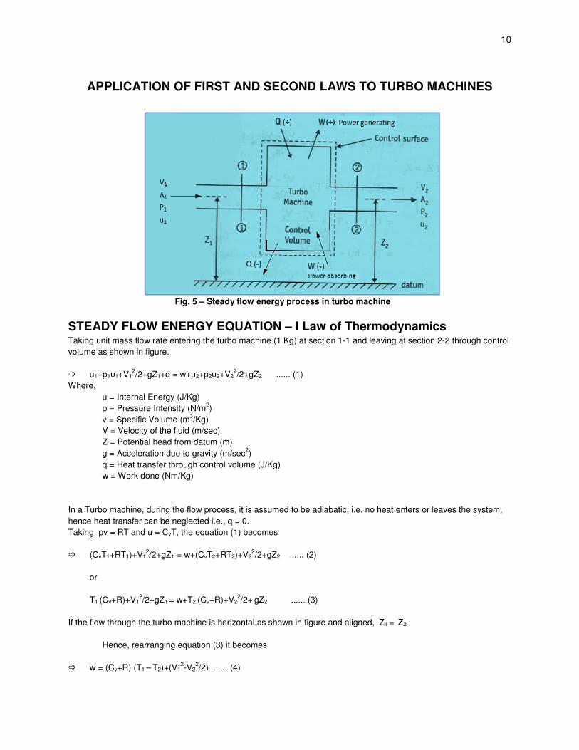
APPLICATION OF FIRST AND SECOND LAWS TO TURBO MACHINES
Fig. 5 – Steady flow energy process in turbo
STEADY FLOW ENERGY EQUATION Taking unit mass flow rate entering the turbo machine (1 Kg) at section 1
volume as shown in figure.
� u1+p1υ1+V12/2+gZ1+q = w+u2+p2υ2
Where,
u = Internal Energy (J/Kg)
p = Pressure Intensity (N/m2)
v = Specific Volume (m3/Kg)
V = Velocity of the fluid (m/sec)
Z = Potential head from datum (m)
g = Acceleration due to gravity (m/sec
q = Heat transfer through control volume (J/Kg)
w = Work done (Nm/Kg)
In a Turbo machine, during the flow process, it is assumed to be adiabatic, i.e. no heat enters or leaves the system,
hence heat transfer can be neglected i.e., q = 0.
Taking pv = RT and u = CvT, the equation (1) becomes
� (CvT1+RT1)+V12/2+gZ1 = w+(CvT2+RT
or
T1 (Cv+R)+V12/2+gZ1 = w+T2 (Cv+R)+V
If the flow through the turbo machine is horizontal as shown in figure and aligned, Z
Hence, rearranging equation (3) it becomes
� w = (Cv+R) (T1 – T2)+(V12-V2
2/2) ...... (4)
APPLICATION OF FIRST AND SECOND LAWS TO TURBO MACHINES
Steady flow energy process in turbo machine
STEADY FLOW ENERGY EQUATION – I Law of Thermodynamics Taking unit mass flow rate entering the turbo machine (1 Kg) at section 1-1 and leaving at section 2
2+V22/2+gZ2 ...... (1)
Velocity of the fluid (m/sec)
Potential head from datum (m)
Acceleration due to gravity (m/sec2)
gh control volume (J/Kg)
In a Turbo machine, during the flow process, it is assumed to be adiabatic, i.e. no heat enters or leaves the system,
hence heat transfer can be neglected i.e., q = 0.
T, the equation (1) becomes
+RT2)+V22/2+gZ2 ...... (2)
+R)+V22/2+ gZ2 ...... (3)
If the flow through the turbo machine is horizontal as shown in figure and aligned, Z1 = Z2
Hence, rearranging equation (3) it becomes
/2) ...... (4)
10
APPLICATION OF FIRST AND SECOND LAWS TO TURBO MACHINES
I Law of Thermodynamics 1 and leaving at section 2-2 through control
In a Turbo machine, during the flow process, it is assumed to be adiabatic, i.e. no heat enters or leaves the system,

VTU eNotes On Turbo Machines(Mechanical Engineering)
Publisher : VTU eLearning Author : Panel Of Experts
Type the URL : http://www.kopykitab.com/product/9157
Get this eBook
50%OFF