tunneling design in autodesk® autocad® civil 3d® and...
TRANSCRIPT

Tunneling Design in Autodesk® AutoCAD® Civil 3D® and Autodesk® Revit® Structure
Edmundo Herrera, P.E. – Autodesk, Inc.
CI1671 The class will focus on how to create model solids for tunnels in Autodesk AutoCAD Civil 3D software. Users will learn how Civil 3D interacts with Autodesk Revit Structure software and how to manipulate tunnel solids, obtain drawings, and create reports, volumetrics, and visualization in Revit Structure. The class will also address on how to Place Rebar on Tunnel Solids in Revit Structure . Finally, users will learn how to model a tunnel natively in Revit Structure and export it to Civil 3D.
Learning Objectives At the end of this class, you will be able to:
Build tunnel solids in Civil3D
Importing Civil3D solids into Revit
Place Rebar on Tunnel Solids
Compute Volumes, Drawings and Reports into Revit
Create a Tunnel in Revit and export to Civil3D
About the Speaker
Transportation Engineer for Autodesk's civil engineering and structural engineering
applications, including Civil 3D, Infraworks and Revit Structural. Responsible for pre-sales
presentations of Autodesk’s civil engineering/structural products as well as development of
techniques for improving and optimizing customer’s daily workflows. Proven history of civil
engineering software deployments at several DOT’s, private and public companies in the US,
Canada, Latin America, Europe and the Middle East for more than 18 years.
Contact: [email protected]
Tunneling Design in Autodesk® AutoCAD® Civil 3D® and Autodesk® Revit® Structure
2
Build Solids in Civil3D
1. Using Civil3D, open the Tunnel.dwg file located under the class file directory.
The file contains a horizontal alignment, a profile surface and a proposed profile.
2. If the Tool Palettes Civil Metric Subassemblies is not displayed, press the Ctrl and 3
keys simultaneously from the keyboard to visualize it.
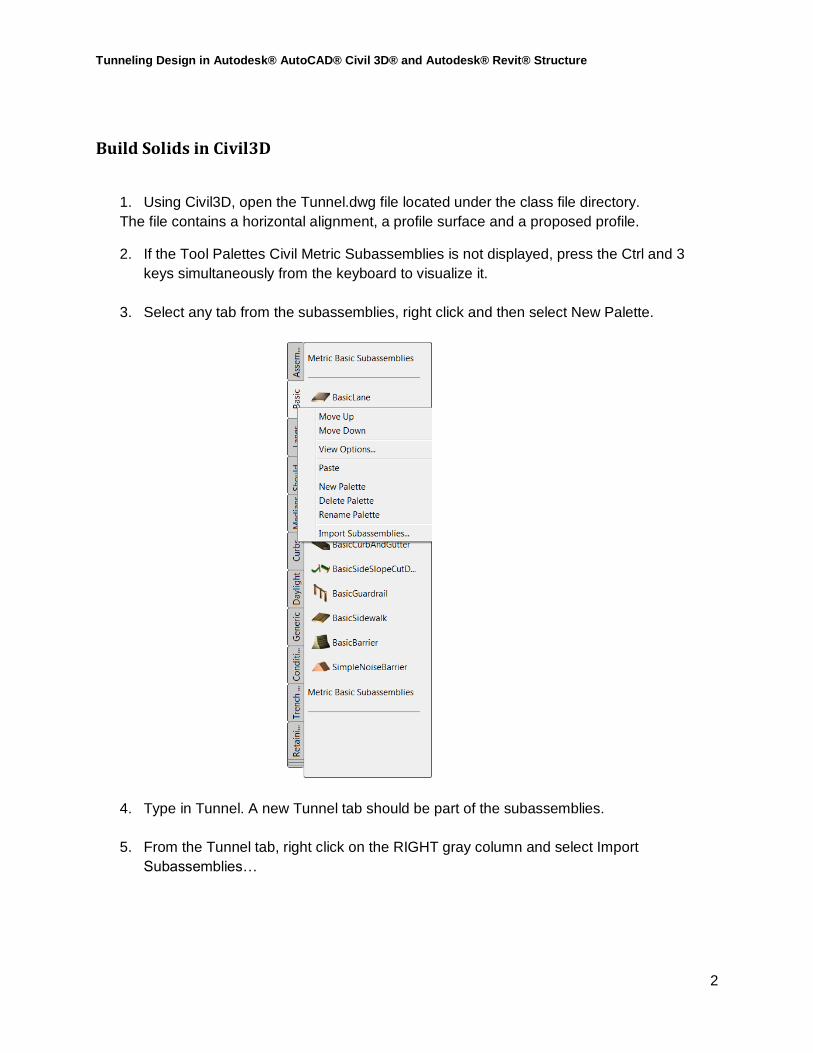
3. Select any tab from the subassemblies, right click and then select New Palette.
4. Type in Tunnel. A new Tunnel tab should be part of the subassemblies.
5. From the Tunnel tab, right click on the RIGHT gray column and select Import
Subassemblies…

Tunneling Design in Autodesk® AutoCAD® Civil 3D® and Autodesk® Revit® Structure
3
6. Select the Tunnel.pkt file from the working class directory. Import it to the Tunnel Palette.
7. From the Civil3D ribbon Home tab, select Assembly > Create Assembly.
8. Keyin Tunnel on the Name field, and select OK. Place the marker anywhere on the file.

Tunneling Design in Autodesk® AutoCAD® Civil 3D® and Autodesk® Revit® Structure
4
9. Click on the Tunnel name on the subassemblies menu, the properties dialog box will
appear and click on the marker. The tunnel subassembly will appear on the drawing:
Close the properties dialog box.
10. From the Ribbon, select the Home tab > Corridor command. Type in Tunnel under
Name, select bl for the Alignment and Profile and Tunnel for the Assembly. Do not mind
about the Target Surface and turn on Set baseline and region parameters. Select OK.
Tunneling Design in Autodesk® AutoCAD® Civil 3D® and Autodesk® Revit® Structure
5
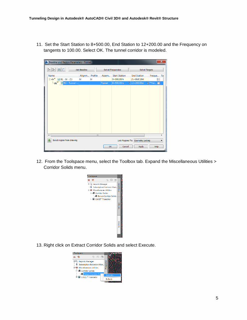
11. Set the Start Station to 8+500.00, End Station to 12+200.00 and the Frequency on
tangents to 100.00. Select OK. The tunnel corridor is modeled.
12. From the Toolspace menu, select the Toolbox tab. Expand the Miscellaneous Utilities >
Corridor Solids menu.
13. Right click on Extract Corridor Solids and select Execute.

Tunneling Design in Autodesk® AutoCAD® Civil 3D® and Autodesk® Revit® Structure
6
14. Highlight the first row on the dialog box and select the Add All Baseline Regions option.
The Regions, Start Station, End Station values are automatically computed.
15. From the left side of the window, select Output Options and select Add to a new
drawing. Name the file Solids.dwg and place it under the working class directory:
Select Create Solids from the bottom of the dialog box. The Solids file is created. Select
Cancel at the bottom of the dialog box.

Tunneling Design in Autodesk® AutoCAD® Civil 3D® and Autodesk® Revit® Structure
7
16. Open the Solids file recently created. Zoom Extents to visualize the content. The tunnel
solids are displayed. Right click on the solid and select Object Viewer. The tunnel solid is
visualized:
17. Close the Object Viewer window.
Tunneling Design in Autodesk® AutoCAD® Civil 3D® and Autodesk® Revit® Structure
8
Importing Civil3D Solids into Revit
Creating Families in Revit from Solids.
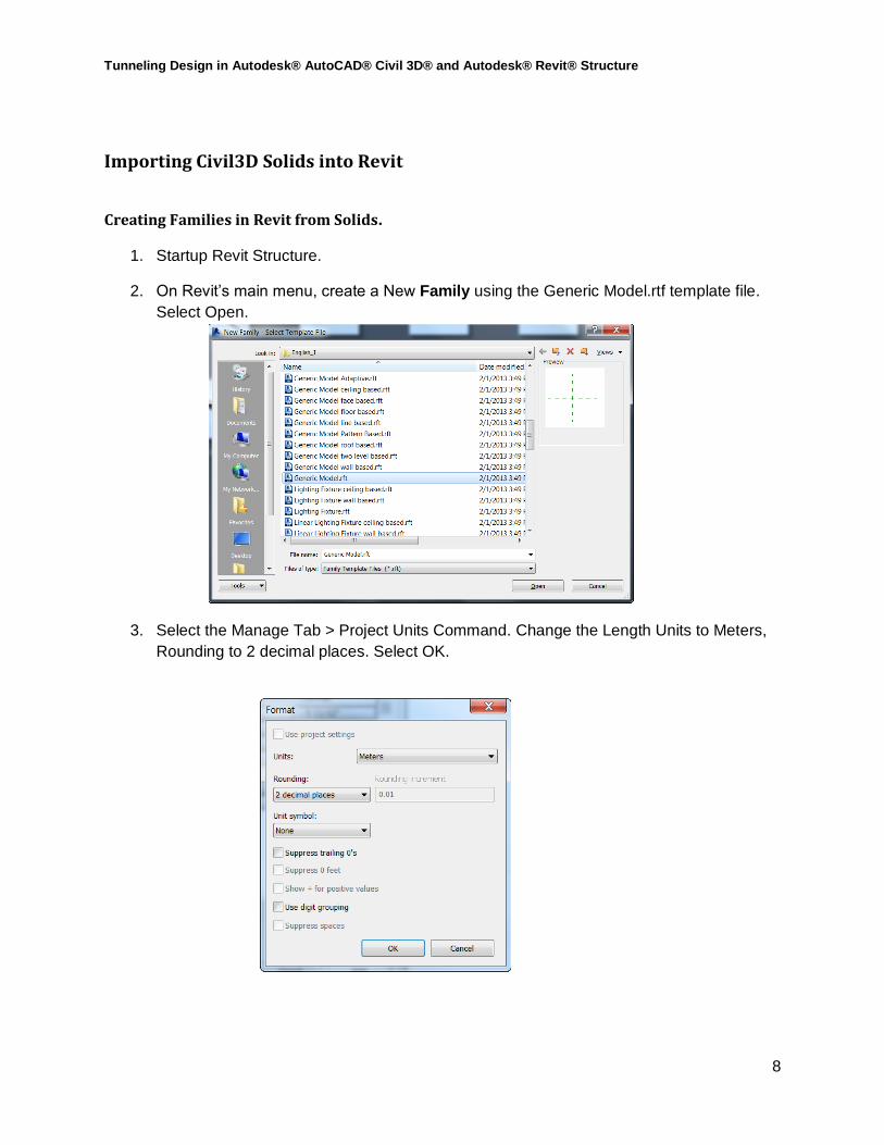
1. Startup Revit Structure.
2. On Revit’s main menu, create a New Family using the Generic Model.rtf template file.
Select Open.
3. Select the Manage Tab > Project Units Command. Change the Length Units to Meters,
Rounding to 2 decimal places. Select OK.

Tunneling Design in Autodesk® AutoCAD® Civil 3D® and Autodesk® Revit® Structure
9
4. Change the Area to m2,Select OK.
5. Select the Insert Tab from the Ribbon, Import CAD command. Select the Solids.dwg file
created on the previous exercise located on the working file directory. Select the Import
units to meter, leave the rest of the default values. Select Open.
6. Disregard the Import Geometry Not Visible message by selecting Close. Close as well
the warning window that appears upon importing.
7. From the Project browser on the left side of Revit, select under Floor Plans > Ref. Level.
By doing so, the Properties window appears at the top. Scroll down until you find View
Range Edit…

Tunneling Design in Autodesk® AutoCAD® Civil 3D® and Autodesk® Revit® Structure
10
Select the Edit… button. Change the Top, Bottom and Level values to Unlimited. Select
OK.
8. Click anywhere in the blank space on the screen. On the left side of the screen, in the
Properties window, turn on Can host rebar.

Tunneling Design in Autodesk® AutoCAD® Civil 3D® and Autodesk® Revit® Structure
11
9. From the upper left corner of Revit, select the R icon > Save As> Family. Name the file
Tunnel.rfa. Place it under the working file directory. Select Save.
10. From Revit, select R icon > Close.
Place Rebar on Tunnel Solids
Transverse Rebar
1. Select New Project. Use the Structural Template File. Select OK.
2. From the Screen, select with the mouse all the default symbols. Select the delete key on
the keyboard to erase all existing symbols delivered with the template. Select OK to
accept.
3. Select the Manage tab from the ribbon > Project Units. Change the Length and Area,
values to the same settings as done in the families. Select OK.

Tunneling Design in Autodesk® AutoCAD® Civil 3D® and Autodesk® Revit® Structure
12
4. From the Structure tab, select Component > Place a Component. From the new created
tab select, Modify | Place Component > Load Family. Load the Tunnel.rfa file created on
the families section. Select Open. Click anywhere on the blank drawing Level 2 window.
Close the warning window.
5. From the left side of Revit, under the Project Browser window, highlight the Level 2
Structural Plan view. By doing so, the Properties window appears at the top. Scroll down
until you find View Range Edit…

Tunneling Design in Autodesk® AutoCAD® Civil 3D® and Autodesk® Revit® Structure
13
6. Select the Edit… button. Change the Top, Bottom and Level values to Unlimited. Select
OK.
The tunnel solids are now visualized on the Level 2 window.
7. Zoom to the upper left corner of the tunnel:
8. From the Ribbon, select under Structure tab > Work Plane > Ref Plane

Tunneling Design in Autodesk® AutoCAD® Civil 3D® and Autodesk® Revit® Structure
14
9. From the Modify | Place Reference Plane command, select the green line with the arrow
icon (Pick Lines), and select the middle longitudinal line to become a new reference
plane.
10. From the View tab, select the Section command. Place the Starting point at the top of
the solid, drag the symbol down until the symbol locks visually perpendicular to the
reference plane. A new section view is created.

Tunneling Design in Autodesk® AutoCAD® Civil 3D® and Autodesk® Revit® Structure
15
11. Double click on the section symbol. The section view is automatically opened:
12. Select from the Structure tab > Work Plane > the Ref Plane command. From the Modify |
Place Reference Plane command, under the Draw command, select Line
Type 0.10 for the Offset located at the bottom left of the Modify |Place Reference Plane.
13. Draw a line representing the reference plane from the external bottom left corner of the
tunnel to the external right corner of the tunnel. Notice that the reference plane will be
offset 0.10 as desired (representing the cover):
Tunneling Design in Autodesk® AutoCAD® Civil 3D® and Autodesk® Revit® Structure
16
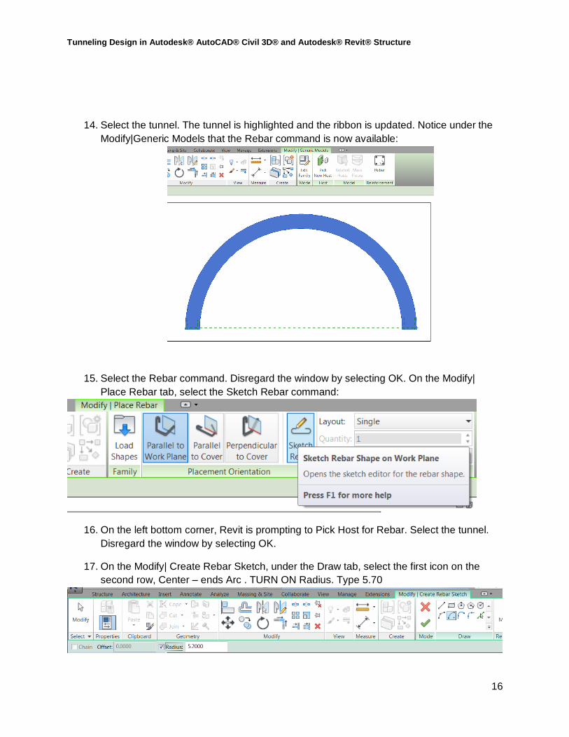
14. Select the tunnel. The tunnel is highlighted and the ribbon is updated. Notice under the
Modify|Generic Models that the Rebar command is now available:
15. Select the Rebar command. Disregard the window by selecting OK. On the Modify|
Place Rebar tab, select the Sketch Rebar command:
16. On the left bottom corner, Revit is prompting to Pick Host for Rebar. Select the tunnel.
Disregard the window by selecting OK.
17. On the Modify| Create Rebar Sketch, under the Draw tab, select the first icon on the
second row, Center – ends Arc . TURN ON Radius. Type 5.70

Tunneling Design in Autodesk® AutoCAD® Civil 3D® and Autodesk® Revit® Structure
17
18. For the Center Point, select the intersection of the planes:
19. For the Arc Start Point, select the left side. Revit will automatically snap to the reference
plane at the correct radius from the Center:
Tunneling Design in Autodesk® AutoCAD® Civil 3D® and Autodesk® Revit® Structure
18
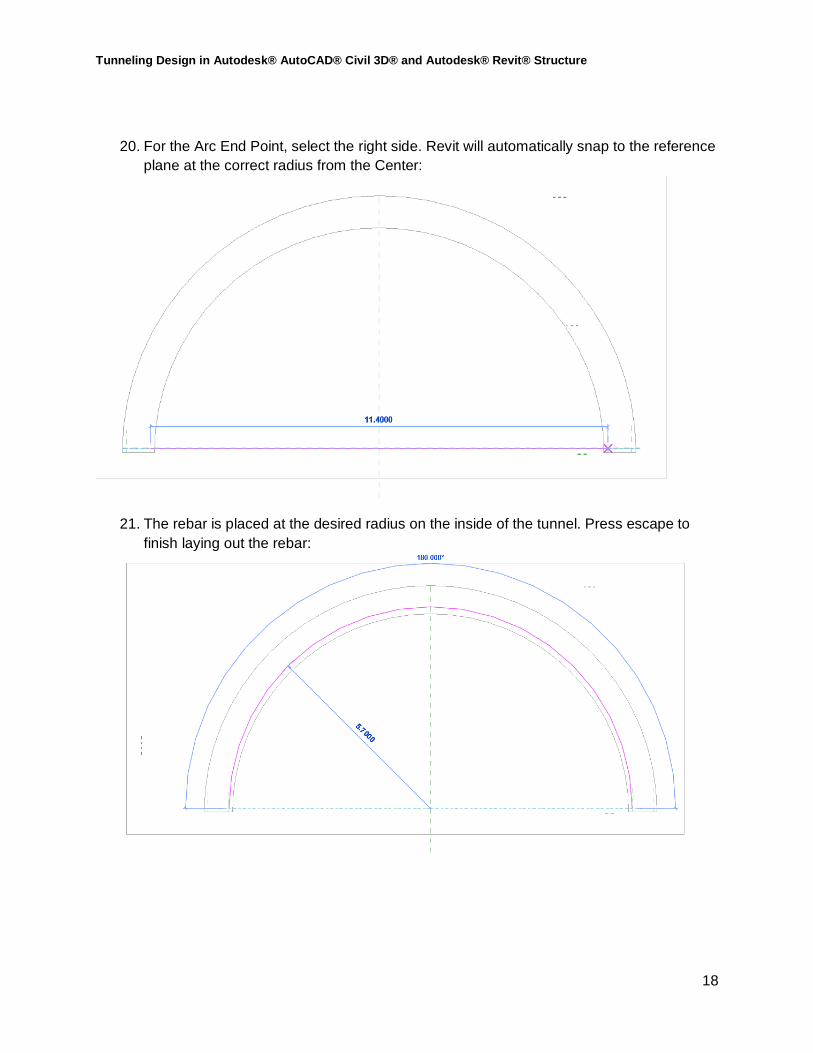
20. For the Arc End Point, select the right side. Revit will automatically snap to the reference
plane at the correct radius from the Center:
21. The rebar is placed at the desired radius on the inside of the tunnel. Press escape to
finish laying out the rebar:
Tunneling Design in Autodesk® AutoCAD® Civil 3D® and Autodesk® Revit® Structure
19
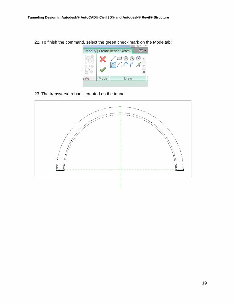
22. To finish the command, select the green check mark on the Mode tab:
23. The transverse rebar is created on the tunnel.

Tunneling Design in Autodesk® AutoCAD® Civil 3D® and Autodesk® Revit® Structure
20
24. Repeat the same process for the external transverse rebar. Use a 6.20 Radius:
25. At the very top of the menu, select the house icon to open up a 3D view:

Tunneling Design in Autodesk® AutoCAD® Civil 3D® and Autodesk® Revit® Structure
21
26. Navigate to the top left corner on the tunnel. Use the Cube to rotate the tunnel view to
visualize the rebar in isometric:
27. Click on any of the rebar elements. Notice the Ribbon changing to Modify | Structural
Rebar. The layout for the moment is Single.

Tunneling Design in Autodesk® AutoCAD® Civil 3D® and Autodesk® Revit® Structure
22
28. Change the Layout to Fixed Number. For the Quantity, type in 1000.00
One thousand rebar elements are placed along the tunnel.
29. Repeat the same process for the other transverse single rebar element:

Tunneling Design in Autodesk® AutoCAD® Civil 3D® and Autodesk® Revit® Structure
23
Longitudinal Rebar
1. Switch to Section 1 (Project Browser in Revit > Sections > Double click on Section 1)
`
2. From the View tab, Create a Section View along the Vertical Reference Plane:

Tunneling Design in Autodesk® AutoCAD® Civil 3D® and Autodesk® Revit® Structure
24
3. Double click on the symbol to open up Section View 2. Zoom to the left side of the
tunnel:
4. Highlight the BOTTOM rebar set. Right click and select Hide in View > Elements. The
bottom transverse rebar set is hidden from the section view.

Tunneling Design in Autodesk® AutoCAD® Civil 3D® and Autodesk® Revit® Structure
25
5. Highlight the Tunnel Solid. From the Modify | Generic Models tab, select the Rebar
command. Select Sketch Rebar and select the Tunnel Solid again. Select the Line
command from Modify | Create Rebar Sketch > Draw
6. To place the line start point, zoom closely to the left side of the tunnel visualizing the first
top transverse rebar.
`

Tunneling Design in Autodesk® AutoCAD® Civil 3D® and Autodesk® Revit® Structure
26
7. Select the intersection of the transverse rebar with the longitudinal line of the solid.
8. Drag the line to the right, zoom out and find the last transverse rebar on the right side of
the tunnel to finish the first longitudinal rebar:
9. Press the escape key to exit out of the command. Select the green check mark under
Modify | Create Rebar Sketch to finalize placing the rebar. The longitudinal rebar at the
top layer of the tunnel is placed.

Tunneling Design in Autodesk® AutoCAD® Civil 3D® and Autodesk® Revit® Structure
27
10. Switch to Section 1 (Project Browser in Revit > Sections > Double click on Section 1).
Zoom to the center at the top layer transverse rebar location. Notice the dot depicting the
longitudinal recently placed rebar.
11. Select the Longitudinal bar (Data point from left to right to encompass the entire rebar).
The ribbon changes. Select the Modify | Structural Rebar tab > Array icon (Four
squares)
Tunneling Design in Autodesk® AutoCAD® Civil 3D® and Autodesk® Revit® Structure
28
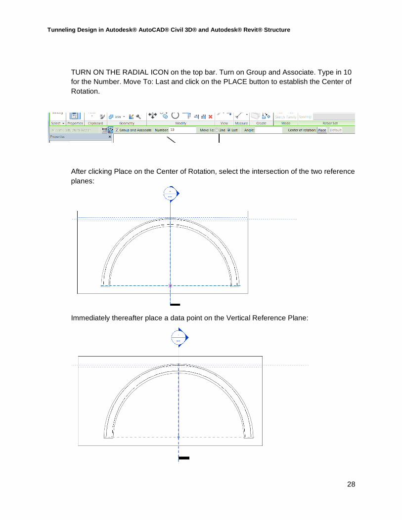
TURN ON THE RADIAL ICON on the top bar. Turn on Group and Associate. Type in 10
for the Number. Move To: Last and click on the PLACE button to establish the Center of
Rotation.
After clicking Place on the Center of Rotation, select the intersection of the two reference
planes:
Immediately thereafter place a data point on the Vertical Reference Plane:
Tunneling Design in Autodesk® AutoCAD® Civil 3D® and Autodesk® Revit® Structure
29
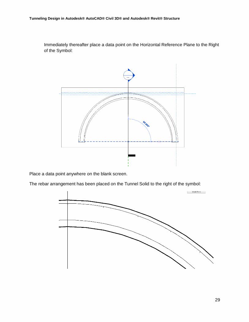
Immediately thereafter place a data point on the Horizontal Reference Plane to the Right
of the Symbol:
Place a data point anywhere on the blank screen.
The rebar arrangement has been placed on the Tunnel Solid to the right of the symbol:

Tunneling Design in Autodesk® AutoCAD® Civil 3D® and Autodesk® Revit® Structure
30
12. Repeat the same process to create an array to the left of the symbol. Both sides should
now be completed:
13. Switch to the Section 2 View. Zoom to the left top corner of the solid:
14. From the bottom of the Window, select the light bulb icon: Reveal Hidden Elements:

Tunneling Design in Autodesk® AutoCAD® Civil 3D® and Autodesk® Revit® Structure
31
15. The bottom transverse element is revealed.
Highlight any of the transverse elements. Select Unhide in View > Elements.
At the bottom of the window, click again on the light bulb icon Close Reveal Hidden
Elements. The bottom rebar elements are now re-visualized on the Window.
Tunneling Design in Autodesk® AutoCAD® Civil 3D® and Autodesk® Revit® Structure
32
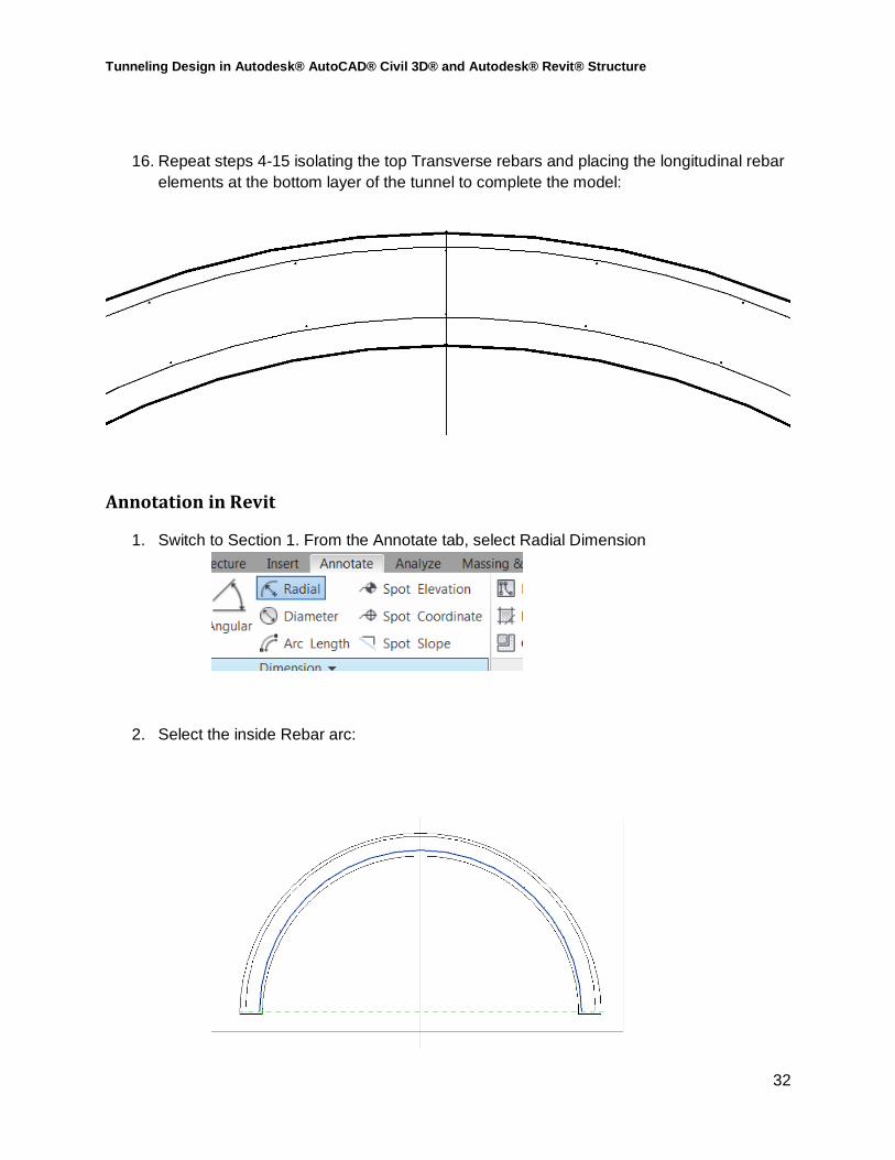
16. Repeat steps 4-15 isolating the top Transverse rebars and placing the longitudinal rebar
elements at the bottom layer of the tunnel to complete the model:
Annotation in Revit
1. Switch to Section 1. From the Annotate tab, select Radial Dimension
2. Select the inside Rebar arc:

Tunneling Design in Autodesk® AutoCAD® Civil 3D® and Autodesk® Revit® Structure
33
Select the Center of the tunnel. The Radial dimension is placed:
3. Repeat the dimension for the External Transverse rebar:
Tunneling Design in Autodesk® AutoCAD® Civil 3D® and Autodesk® Revit® Structure
34
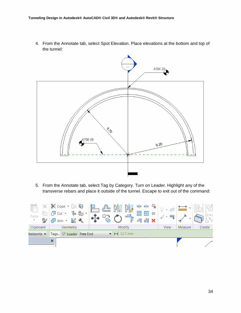
4. From the Annotate tab, select Spot Elevation. Place elevations at the bottom and top of
the tunnel:
5. From the Annotate tab, select Tag by Category. Turn on Leader. Highlight any of the
transverse rebars and place it outside of the tunnel. Escape to exit out of the command:

Tunneling Design in Autodesk® AutoCAD® Civil 3D® and Autodesk® Revit® Structure
35
6. Highlight the default rebar annotation. On the left side of Revit, under Properties, select
Edit Type.
Under Type Properties, turn off Type, Turn on Quantity Type & Spacing – 2 Line and for
the Leader Arrowhead, select Arrow Filled 20 Degrees. Select OK.

Tunneling Design in Autodesk® AutoCAD® Civil 3D® and Autodesk® Revit® Structure
36
7. The rebar is now annotated with diameter, number of elements:

Tunneling Design in Autodesk® AutoCAD® Civil 3D® and Autodesk® Revit® Structure
37
Reporting in Revit
1. From the Project Browser on the left side of Revit, right click on Schedule/Quantities and
select New Schedule/Quantities:
2. On the New Schedule window, select the Structural Rebar Category on the left side.
Type Tunnel Rebar Schedule. Select OK:
Tunneling Design in Autodesk® AutoCAD® Civil 3D® and Autodesk® Revit® Structure
38
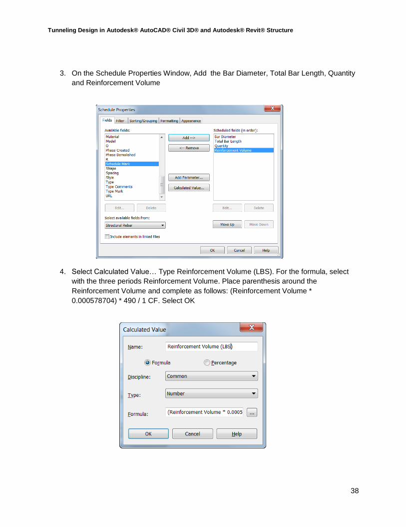
3. On the Schedule Properties Window, Add the Bar Diameter, Total Bar Length, Quantity
and Reinforcement Volume
4. Select Calculated Value… Type Reinforcement Volume (LBS). For the formula, select
with the three periods Reinforcement Volume. Place parenthesis around the
Reinforcement Volume and complete as follows: (Reinforcement Volume *
0.000578704) * 490 / 1 CF. Select OK

Tunneling Design in Autodesk® AutoCAD® Civil 3D® and Autodesk® Revit® Structure
39
5. The report is created:
Tunneling Design in Autodesk® AutoCAD® Civil 3D® and Autodesk® Revit® Structure
40
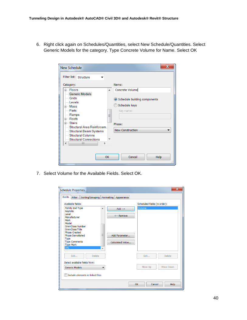
6. Right click again on Schedules/Quantities, select New Schedule/Quantities. Select
Generic Models for the category. Type Concrete Volume for Name. Select OK
7. Select Volume for the Available Fields. Select OK.

Tunneling Design in Autodesk® AutoCAD® Civil 3D® and Autodesk® Revit® Structure
41
8. The concrete volume report is created:
Drawing Composition in Revit
1. From the Project Browser on the left side of Revit, right click on Sheets (all) and select
New Sheet:
2. On the New Sheet dialog box, select Load…Scroll down to the bottom of the available
directories list. Double click on Titleblocks. Select D 22 x 34 Horizontal.rfa. Select Open.
Select OK.

Tunneling Design in Autodesk® AutoCAD® Civil 3D® and Autodesk® Revit® Structure
42
3. From the available Sections list, drag the Section 1 view to the drawing sheet.
4. Drag the Tunnel Rebar Schedule to the current Sheet.
Note that if any of the rebar diameters change, the schedule will be automatically updated.
5. From the R icon in Revit, select Save. Save the .rvt project on the class working
directory.
Tunneling Design in Autodesk® AutoCAD® Civil 3D® and Autodesk® Revit® Structure
43
Creating a Tunnel in Revit Native Format
Creating a Typical Section inside a Revit Family
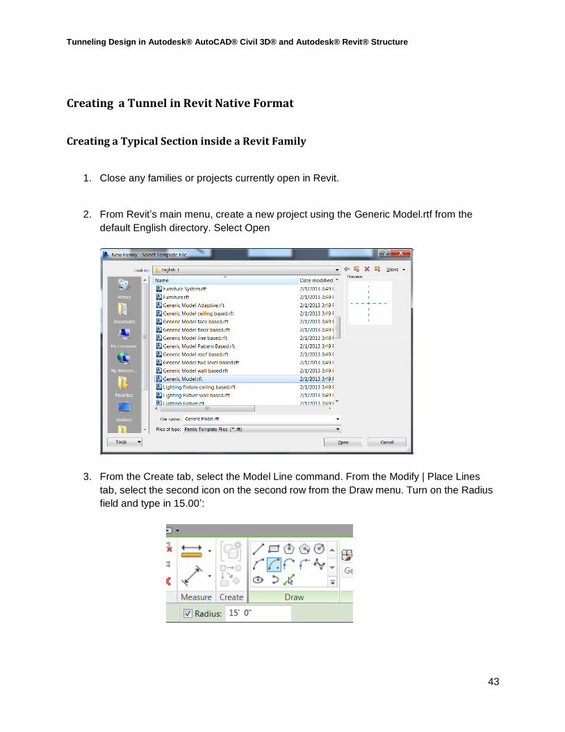
1. Close any families or projects currently open in Revit.
2. From Revit’s main menu, create a new project using the Generic Model.rtf from the
default English directory. Select Open
3. From the Create tab, select the Model Line command. From the Modify | Place Lines
tab, select the second icon on the second row from the Draw menu. Turn on the Radius
field and type in 15.00’:

Tunneling Design in Autodesk® AutoCAD® Civil 3D® and Autodesk® Revit® Structure
44
4. Place the center at the intersection of the reference planes, place a data point to the
right and sweep the arc to the left
Until the arc is locked to 180 degrees. Press the Escape Key to exit the
command:
Tunneling Design in Autodesk® AutoCAD® Civil 3D® and Autodesk® Revit® Structure
45
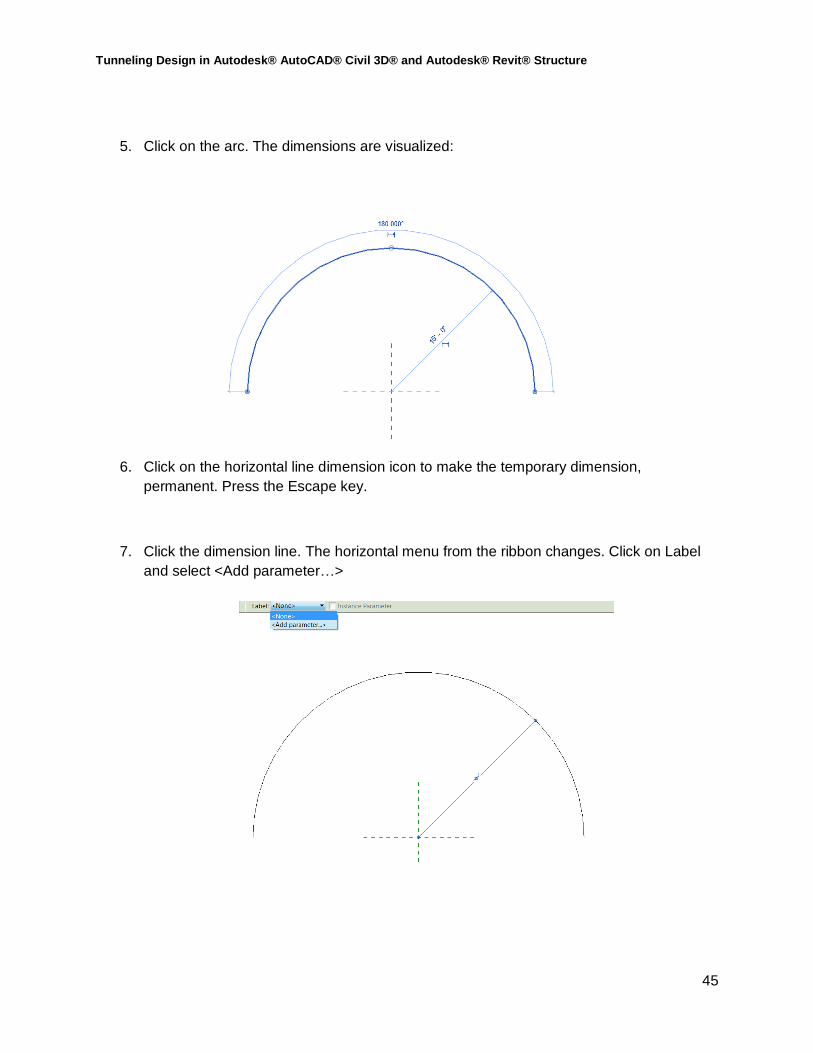
5. Click on the arc. The dimensions are visualized:
6. Click on the horizontal line dimension icon to make the temporary dimension,
permanent. Press the Escape key.
7. Click the dimension line. The horizontal menu from the ribbon changes. Click on Label
and select <Add parameter…>
Tunneling Design in Autodesk® AutoCAD® Civil 3D® and Autodesk® Revit® Structure
46
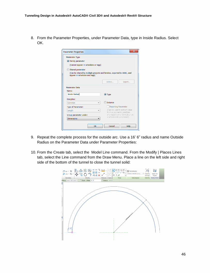
8. From the Parameter Properties, under Parameter Data, type in Inside Radius. Select
OK.
9. Repeat the complete process for the outside arc. Use a 16’ 6” radius and name Outside
Radius on the Parameter Data under Parameter Properties:
10. From the Create tab, select the Model Line command. From the Modify | Places Lines
tab, select the Line command from the Draw Menu. Place a line on the left side and right
side of the bottom of the tunnel to close the tunnel solid:
Tunneling Design in Autodesk® AutoCAD® Civil 3D® and Autodesk® Revit® Structure
47
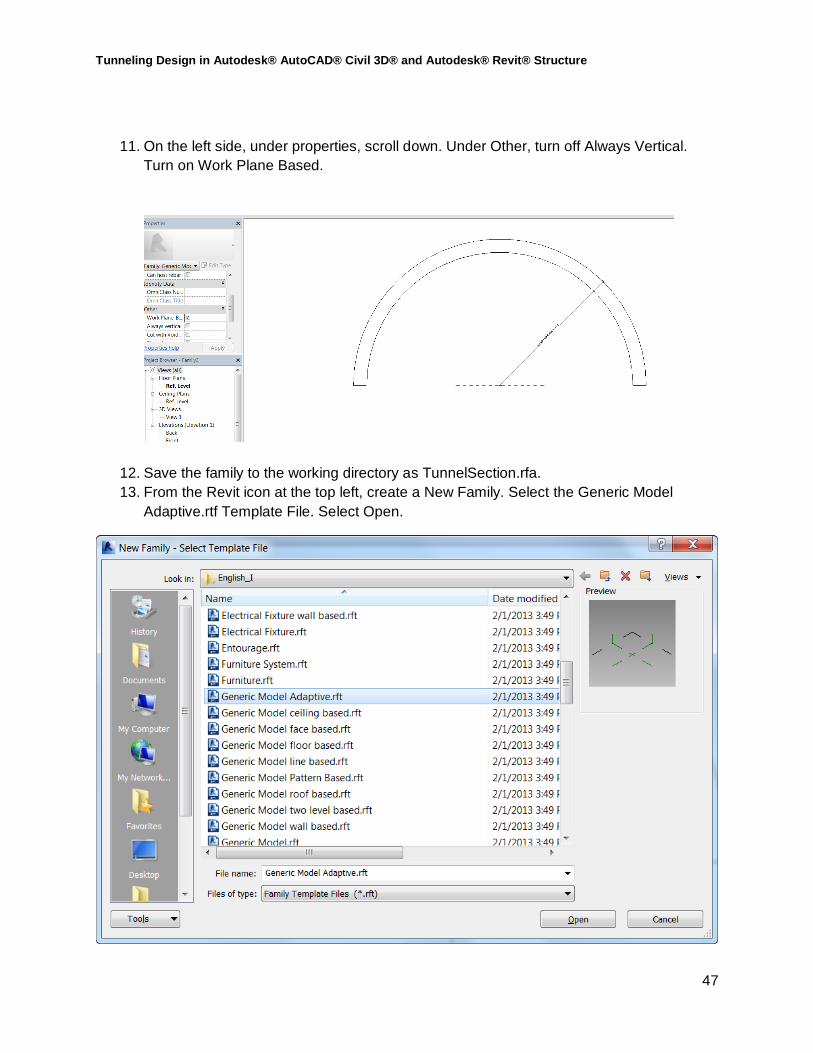
11. On the left side, under properties, scroll down. Under Other, turn off Always Vertical.
Turn on Work Plane Based.
12. Save the family to the working directory as TunnelSection.rfa.
13. From the Revit icon at the top left, create a New Family. Select the Generic Model
Adaptive.rtf Template File. Select Open.

Tunneling Design in Autodesk® AutoCAD® Civil 3D® and Autodesk® Revit® Structure
48
14. On the left side, under Project Browser > Floor Plans, double click on Ref. Level.
15. From the Create tab, on the Draw Menu, click on Reference lines on the Draw menu and
then select Spline Through Points.
16. Place the first line at the intersection of planes, and then place two points to the right at
any location along the reference horizontal plane.
17. Switch to the {3D} View
Tunneling Design in Autodesk® AutoCAD® Civil 3D® and Autodesk® Revit® Structure
49
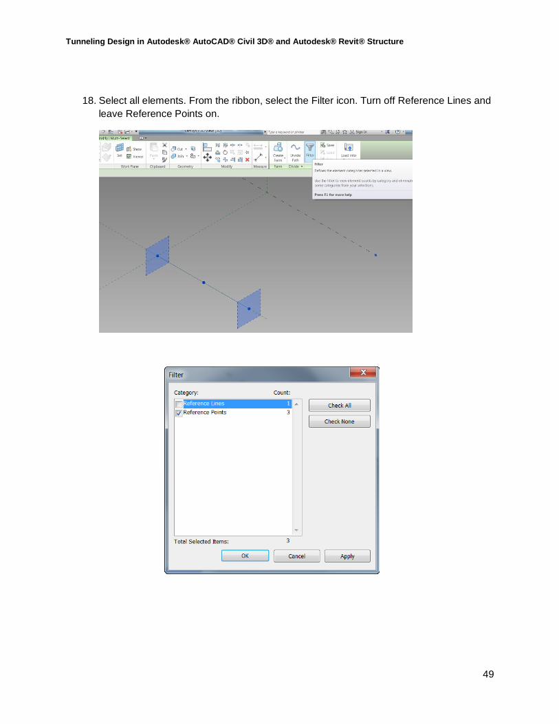
18. Select all elements. From the ribbon, select the Filter icon. Turn off Reference Lines and
leave Reference Points on.

Tunneling Design in Autodesk® AutoCAD® Civil 3D® and Autodesk® Revit® Structure
50
19. From the ribbon, select Make Adaptive from the Adaptive Component menu. The points
are now adaptive.
20. On the Create tab, select the Set Work Plane Command from the Work Plane menu
21. Select the plane normal to the horizontal axis on the first point of the reference line.

Tunneling Design in Autodesk® AutoCAD® Civil 3D® and Autodesk® Revit® Structure
51
22. From the Insert tab in Revit, select Import Family and load the TunnelSection family
previously created.
23. From the left side of the Project, under the Project Browser window, select Families,
expand the Generic Model family and find Tunnel Section. Right Click and select Create
Instance.
24. From the Ribbon, select Place on Work Plane.
25. Place the section at the first point.
Tunneling Design in Autodesk® AutoCAD® Civil 3D® and Autodesk® Revit® Structure
52
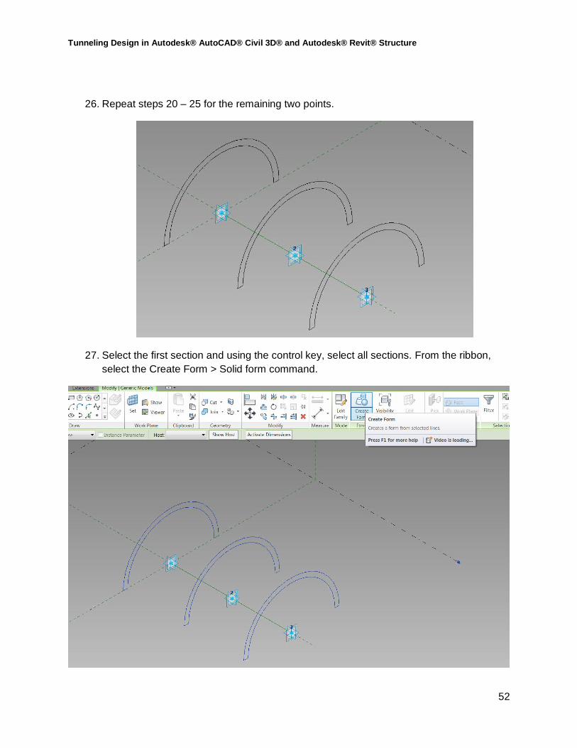
26. Repeat steps 20 – 25 for the remaining two points.
27. Select the first section and using the control key, select all sections. From the ribbon,
select the Create Form > Solid form command.
Tunneling Design in Autodesk® AutoCAD® Civil 3D® and Autodesk® Revit® Structure
53
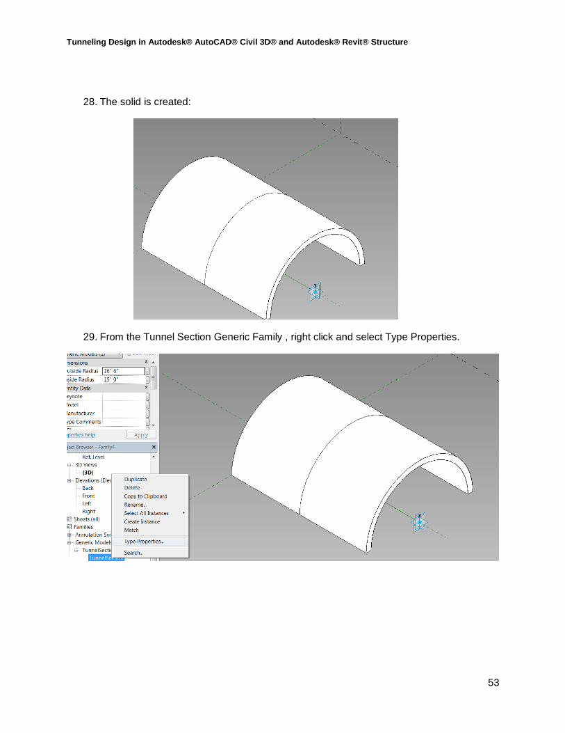
28. The solid is created:
29. From the Tunnel Section Generic Family , right click and select Type Properties.

Tunneling Design in Autodesk® AutoCAD® Civil 3D® and Autodesk® Revit® Structure
54
30. Change the Outside Radius to 18’. Select OK. The solid automatically changes.
31. Save the family as Adaptive Tunnel
32. From the Revit R icon on the top left side, create a new project.
33. From the Structure tab, select Component. From the Modify | Place Component, select
Load Family. Load the Adaptive Tunnel family.
34. Place the component on the top view by clicking three points for the tunnel geometry

Tunneling Design in Autodesk® AutoCAD® Civil 3D® and Autodesk® Revit® Structure
55
35. Open a 3D view. Since the primitive section was constructed in the opposite order, the
tunnel will be upside down:
36. Highlight the solid. From the left side in Revit, under Properties, scroll down and turn on
Flip on Adaptive Component. Select Apply.
37. The tunnel is correctly placed.

Tunneling Design in Autodesk® AutoCAD® Civil 3D® and Autodesk® Revit® Structure
56
38. Save the project. If the solid wants to be exported to Civil 3D, select Export > CAD
Formats. The solid can be exported to a dwg, dxf , dgn or a solid format (.sat).