tst a-pfn 2018 engtstsan.com/__files__/dosyalar/tst_a_pfn_2018eng.pdf · 2018-11-07 · a-pfn nail...
TRANSCRIPT

Medical Devices
A-PFN Antirotator Proximal Femoral Nail
PATENTED

Introductions
Table of Contents
IntroductionsIndicationsFeatures
23
1
Surgical Technique5
ImplantsInstruments 1Instruments 2Instruments 3
15171819
15 Set Detail
20 Radiographic Cases
Warning: This descriptive catalog is not sufficient as being unaided for proper use of the products intraoperatively. It is highly
recommended that implantation and instrument sets must be used by a surgeon who is trained-experienced
about the product performances and usage.
Intertrochanteric femoral fractures constitute 10% ofall the bone fractures. They are frequently seen in elderly patients above 65 years.
Proximal femoral fractures frequently occur as a result of ordinary traumas in elderly patients with osteoporosis. Besides, these kinds of fractures rarely occur in young patients who have high energy trauma.
Fractures take place in proximal femur area have an effect on patients' general health and on their psychological, social, economical conditions. Treatment of these fractures may end up with worse results than expected, despite the advanced patient care and surgical techniques in recent years. In some cases, ideal treatment is determined contentiously because of having poor bone quality may accompany systemic diseases.
The purpose of the hip fracture treatment in elderly patients is to return them to their health condition in the pre-fracture level by enabling them to move within the shortest time and avoid complications that can occur due to immobility. In today, sufficient amount of reduction and rigid internal fixation are the most valid treatment methods for unstable intertrochanteric femoral fractures.
Proximal Femoral Nail (PFN) System usage becomes prevalent for fixation among orthopedic surgeons in recent years by means of having anatomical and mechanical biocompatibility.
Intramedullary implants provide better weight distribution over the calcar by means of their medial position when compared to extramedullary implants (DHS-Dynamic Hip Screw) that have usage indications in the treatment of proximal femur fractures. They reduce the risk of implant failure by decreasing the tensile strengths that act on the implant by virtue of their short motion arms. They provide controlled impaction as sliding nails. A closed entry through the entrance hole brings some theoretical advantages such as short operation time, less soft tissue dissection, less bleeding and as the most important one; protection of fracture hematoma which is the main element of bone fusion.
Patients are easily rehabilitated in consequence of weight bearing as early as possible in the postoperative period.

Indications
This feature of the nail brings too many advantages.As a result of sliding, fracture lines are converged thus provides reinforcement to the bone union process.
The length of the moment arm is decreased by telescopic effect which ensures a decrease in bending force over the implant. As a result, fixation failure rate becomes less.
Compressive forces that press to medial are equal with tensile forces that press lateral in stable fractures. However; pressure on the lateral cortex increases in unstable fractures. According to these results -made by considering the hip biomechanics-, there is a similar success rate for using intramedullary and extramedullary implants in stable fractures. Nevertheless, when unstable fractures are taken into consideration, success rate of intramedullary implants is higher and the complication rate is lower.The system has an indication for both stable and unstable fractures, however it is more important for unstable fractures.
Although there are some important advantages of using PFN,considering the amount of bleeding, local or systemiccomplications, stripping, implant inefficacy, mechanical problemsand operation time. Femur diaphysis fracture couldbe seen owing to different reasons such as squeezing of nail inthe medulla because of the nail thickness in some PFN systems,usage of a hammer to send the nail, stress that occurs at the endof the nail due to thickness of the nail distal diameter duringthese operations and in the post-operative period.
Likewise, sending one proximal screw to the collum weakens stability and can not prevent rotation which will occur in the proximal area. It also increases -stress forces thus cut-out risk as well.
Design of proximal femur nails has been changed to minimize complications and improve benefits of these nails which have been used nowadays.
A-PFN which is developed by TST aims to achieve the desired results, enables impaction of the fracture by allowing sliding compression and increases rotational stability by the special blade.
Proximal femur upper fractures; pertrochanteric, intertrochanteric, subtrochanteric fractures are included in the indication field.
2

FeaturesA-PFN nail is developed via making important additions to PFN system. A-PFN nail ensures rotational stability through a special blade which can be sent over the cannulated proximal screw that fronts to the neck with an angle of 125°, allows impaction of fracture by means of sliding compression. Other features of A-PFN are written below.
A body which has a 6° of anatomical angle provides an easy insertion to the trochanter major tip with a little incision.
The proximal diameter of the nail is 16 mm thus minimizes the bone loss.
Cannulated proximal screw that goes to the neck has a collodiaphyseal angle of 125°.
The nail has 4 diameter options of 9, 10, 11, 12 mm and 2 length options of 160-220 mm.
The cannulated structure of the screw enables a guide wire with the diameter of 2.5 mm to pass through itself.
Design of the nail enables to compress femur neck and intertrochanteric space. There is a cannulated proximal lag screw present in the system.
Cannulated proximal lag screw has a special blade gutter to inhibit the femur head rotation.
Special anti-rotator blades with different lengths which are compatible with their proximal cannulated screws can be driven through the gutter so that they provide complete rotational stability.
Cannulated proximal Lag Screw which can be sent over a guide wire and by means of broad cancellous threads of Ø 10 mm, proximal fragment fixing is much better and stronger. A special designed oval hole operating with tap screw enables locking and compression. It has a sliding compression feature nevertheless, it has a special tap screw to inhibit this function. Besides standard tap screws are available too.
Through the unique design of distal locking screw, it is fixed to the driver and possible undesirable conditions such as dropping and wrong way dispatching problems are removed.
The nail driven is facilitated by the inventively head design of distal end and the distal end is formed with distal slit to enable flexibility thus reduce stress focusing.
According to literature, stress forces at the distal part of the short nail may induce femur diaphysis breakage.It is prevented in virtue of this new design.
By means of external modular targeting guide arm and other helper instruments, fast and troubleless placing is ensured.
Nail distal locking is realized by considering condition of the fracture via the static and dynamic holes presentat the distal part by self-tapping cortical screws in the diameter of Ø 5 mm.
By means of the short external guide system, distal locking is accomplished easily.
All of the implants are made of robust and biocompatible implant material which meets the requirements of Ti6Al4V Eli 136 standards.
Lag screw and the blade operates as a monoblock by means of the special locking mechanism in this system, thus the 'Z effect' is removed.
In the A-PFN System the compression can be realized in three different ways:Primary compression by the lag screw, secondary compression by the Cannulated Compression Screw and tertiary compression by the sliding effect.
3

MEDIOLATERALSLOPE6°
collodiaphysial angle125°
LENGTH OPTIONS160-220 mm*h
NAIL BODY DIAMETER 9, 10, 11, 12 mmØ
5 mm increment65 . . . .120 mm
Ti6Al4V Eli F 136biocompatible
material
distal slitwhich enablesstretching thus
reduces stress focusing
compression6mm
COMMONDESIGN FORBOTH LEFTAND RIGHT
12 lag screw
2 mm increment30 . . .48 mm
*optional 320, 340, 360 mm
Ø5 mmself-tappingcortical screw
lag screw Ø 10 mm
compressionend cap
2,5 mmcannulated nail
antirotator blade
cannulatedcompression
screw
staticlocking
hole
dynamiclocking
hole
4

15°
*Axial ve AP View of the Guide Wire Entrance
AnatomicAxis
Guide WirePosition
6°
1 PATIENT POSITION
The patient is placed on the traction table in supine position. Trochanter major is palpated and 5 cm longitudinal incision is made from top to the proximal. Then the reduction is controlled under the fluoroscopy. After achieving the suitable position, it is reached to trochanter major by incision of the skin, subcutaneous and tensor fasciae latae. Gluteus medius is incised parallel to the muscle fibers.
2 NAIL ENTRY POINT
A Ø 2.5 x 400 mm K wire is sent via IM from tip of the trochanter major.
After conforming that the K-Wire is in the medulla from the standpoint of both two plans, femur proximal is carved using AWL over the K-Wire or Trochanteric Reamer with soft tissue protector.
Surgical Technique
5

Screw GuideLocking Device
3 NAIL INSERTING
After designating proper nail with regard to diameter and length, the nail is fixed to Insertion Handle.
The nail is sent under rotational forces through the trochanteric major tip. Hammer should not be used at this stage. If it is not possible to send the nail, one size smaller nail should be sent. If the medullar canal is still tight, the medulla should be widen up to 10 mm.
4 TISSUE PROTECTOR PLACEMENT FOR PROXIMAL SCREW-BLADE
If the nail is placed over the guide wire, K-Wire is taken out.
After sending the nail, tissue protector system (A-PFN Blade Drill & Proximal Screw K-Wire Guide) is placed to send Proximal Lag Screw and the Antirotator Blade.
System is fixed by PFN Screw Guide Locking Device when tissue protector and the bone are in contact.
L
6

120
115
110
105
100
9590
8580
7570
65
160OBL.
OBL.
PRX
ST.
DYN.
DYN.
ST.
160
160
220
220
220
A-PFN5 K -WIRE PLACEMENT FOR BLADE
6 K-WIRE PLACEMENT FOR PROXIMAL SCREW
To send the proximal lag screw, Threaded End Ø 2,5 x 340 mm K-Wire is sent until subchondral area through proximal K-Wire hole which is in the tissue protector. After that, the position is controlled by fluoroscopy.
The K-Wire is always sent 5 mm longer than the planned screw size.
*It is important to pay attention that instruments belong to external targeting guide system such as tissue protector, screw-blade, guide-sleeve should be in complete contact with the bone during applications.
Before sending the screw and blade, the anteversion of the nail should be considered.
To send neck screw and blade, A-PFN Blade K-Wire Guide is placed into the tissue protector, then Ø 2 x 340 mm of K-Wire is sent through it until arriving subchondral part.
After sending Ø 2 x 340 mm of K-Wire, fluoroscopy control is achieved. The K-Wire should be at the down half part of the femoral head on the AP view and be at the center on the lateral view.
If the position is convenient, length is measured by Measuring Device over the K-Wire for proximal screw. The Blade K-Wire Guide is taken off.
MeasuringDevice
7

100
105
110
115
120
120115
110
7 CARVING OPERATIONFOR BLADE
Guide hole is opened by A-PFN Blade Drill over the Ø 2x340 mm of K-Wire exists at the distal for blade.
8 CARVING OPERATION FOR PROXIMAL LAG SCREW
Tissue protector system is changed. A-PFN Blade Drill & Prox. Screw K-Wire Guide is taken off and A-PFN Proximal Screw-Blade Guide is placed instead.
A-PFN Proximal Screw-Reamer Guide is fixed into it then 1. Reamer and 2. Reamer are sent until determined depth thus carving operation is realized.
8

120115
stopper
2. Reamer is used just for widening lateral cortex. A stopper exists on the drill.
9 TAP OPERATION FOR PROXIMAL SCREW
For the Proximal Lag Screw, a threaded guide way is opened by Tap held to the T-Handle. Tapping operation should be done especially on the young patients because of their hard bone structure.
9

5 mm wrench
0
6
laser marksshould be on the same plane
for blade transmission
10A Proximal Screw in the proper length is fixed to A-PFN Proximal Screw Inserter as in the figure.
After pulling out the Proximal Screw Reamer Guide, the Proximal Screw is sent over the K-Wire toward the head. The position of the proximal screw is controlled by the fluoroscopy. Required compression amount (0, 3, 6 mm) is determined by checking window on the tissue protector.
For an accurate placement, laser marks on the Inserter and the Tissue Protector should be on the same plane.
INSERTING OFTHE PROXIMAL SCREW
10

blade
bladeinserter
proximal screwinserter
direction should beplaced upwards
11 INSERTING OF THE BLADE
A-PFN Antirotator Blade which is in the same length with the proximal screw is assembled to the Blade Inserter as in the figure.
Blade is sent after placing to the slide which is in the inferior of Proximal Screw Inserter. It is sent until the sign on the blade inserter that arrives Screw Inserter level with the help of slight Hammer strikes.
In this system, the Blade is settled to blade gutter exists in the inferior of Proximal Screw thus provides rotational stability.
11

staticlocking hole
dynamicloking hole
13 REAMERIZATION FOR DISTAL LOCKING
Proximal Tissue Protector is removed. K-Wire is shortened by cutting until 2-3 cm remains outside the skin.Distal locking changes according to condition of the fracture, however locking is made from proximal
screw hole for static locking and distal screw hole for dynamic locking.Locking can be made using 2 screws for subtrochanteric fractures. According to the static locking or dynamic locking construction, carving is operated for cortical screw over Tissue Protector by 4.2 mm of Drill.
Length is measured for Ø 5 mm of Cortical Screw over Drill Guide, therefore Depth Gauge is available in the set.
12 COMPRESSION SCREW INSERTION
A-PFN Blade Inserter and Inner Part of the Proximal Screw Inserter are removed. Cannulated Compression Screw is sent by Ø 4 mm Cannulated Screw Driver inside of the Proximal Screw Inserter to Proximal Screw as providing 3 or 4 threads held.
12

laser mark
assembling of the distal locking screw to t-handle screw inserter
static and dynamic locking options
14 DISTAL LOCKING
Distal locking is completed after the transfer of Cortical Screw which is assembled to T-Handle Screw Inserter, in available length, through Tissue Protector. It is sent until laser line on the T-Handle Screw Inserter.
13

End Cap should be squeezed after compression.
K-Wire pulls back until Compression Screw to avoid overlapping with End Cap. On the AP view, End Cap should place 1-2 mm above the nail top point and it should not squeeze completely. Because in this system, compression is realized by the Compression Screw operates in interaction with Proximal Screw and End Cap.
Required compression is realized from lateral using Screw Driver Ø 4x175 mm.
*In cases where the fracture impaction is needed End Cap is not squeezed completely thus sliding effect of the system is allowed.
15 END CAP INSERTION ANDCOMPRESSION
Insertion Handle is removed. K-Wire is pulled back until Compression Screw to avoid overlapping with End Cap. End Cap is placed to screw top from proximal of the nail.
Proximal of the end cap should be placed meticulously considering to leave 1-2 mm of it from nail top point, from the standpoint of AP and it should not squeeze completely. Because in this system, compression is ensured by Compression Screw that operates in interaction with Proximal Screw and End Cap.
After that, required compression is realized from lateral using Screw Driver Ø 4x175 mm. This operation can be realized using Cannulated Screwdriver over K-Wire in overweight patients.
End Cap screw should be squeezed completely after compression.
Whether the screws are in screw holes, the lenght and final position of the fracture are controlled via fluoroscopy. After the approval process, the incision area is closed considering subcutaneous layers anatomy.
14
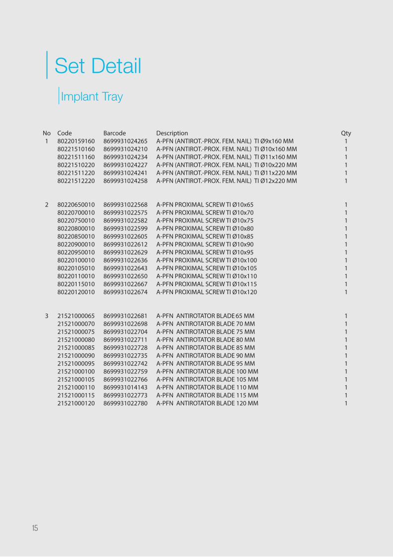
Set DetailImplant Tray
Code802201591608022151016080221511160802215102208022151122080221512220
802206500108022070001080220750010802208000108022085001080220900010802209500108022010001080220105010802201100108022011501080220120010
215210000652152100007021521000075215210000802152100008521521000090215210000952152100010021521000105215210001102152100011521521000120
Barcode869993102426586999310242108699931024234869993102422786999310242418699931024258
869993102256886999310225758699931022582869993102259986999310226058699931022612869993102262986999310226368699931022643869993102265086999310226678699931022674
869993102268186999310226988699931022704869993102271186999310227288699931022735869993102274286999310227598699931022766869993101414386999310227738699931022780
DescriptionA-PFN (ANTIROT.-PROX. FEM. NAIL) TI Ø9x160 MMA-PFN (ANTIROT.-PROX. FEM. NAIL) TI Ø10x160 MMA-PFN (ANTIROT.-PROX. FEM. NAIL) TI Ø11x160 MMA-PFN (ANTIROT.-PROX. FEM. NAIL) TI Ø10x220 MMA-PFN (ANTIROT.-PROX. FEM. NAIL) TI Ø11x220 MMA-PFN (ANTIROT.-PROX. FEM. NAIL) TI Ø12x220 MM
A-PFN PROXIMAL SCREW TI Ø10x65A-PFN PROXIMAL SCREW TI Ø10x70A-PFN PROXIMAL SCREW TI Ø10x75A-PFN PROXIMAL SCREW TI Ø10x80A-PFN PROXIMAL SCREW TI Ø10x85A-PFN PROXIMAL SCREW TI Ø10x90A-PFN PROXIMAL SCREW TI Ø10x95A-PFN PROXIMAL SCREW TI Ø10x100A-PFN PROXIMAL SCREW TI Ø10x105A-PFN PROXIMAL SCREW TI Ø10x110A-PFN PROXIMAL SCREW TI Ø10x115A-PFN PROXIMAL SCREW TI Ø10x120
A-PFN ANTIROTATOR BLADE 65 MMA-PFN ANTIROTATOR BLADE 70 MMA-PFN ANTIROTATOR BLADE 75 MMA-PFN ANTIROTATOR BLADE 80 MMA-PFN ANTIROTATOR BLADE 85 MMA-PFN ANTIROTATOR BLADE 90 MMA-PFN ANTIROTATOR BLADE 95 MMA-PFN ANTIROTATOR BLADE 100 MMA-PFN ANTIROTATOR BLADE 105 MMA-PFN ANTIROTATOR BLADE 110 MMA-PFN ANTIROTATOR BLADE 115 MMA-PFN ANTIROTATOR BLADE 120 MM
Qty111111
111111111111
111111111111
No1
2
3
15

123654
K-Wire pulls back until Compression Screw to avoid overlapping with End Cap. On the AP view, End Cap should place 1-2 mm above the nail top point and it should not squeeze completely. Because in this system, compression is realized by the Compression Screw operates in interaction with Proximal Screw and End Cap.
Code202201001008022010000280220100000
20124300050201243200502012434005020124360050201243800502012440005020124420050201244400502012446005020124480050
06040000604100
Barcode869993102279786999310228278699931022810
8699931022339869993102234686999310223538699931022360869993102237786999310223848699931030945869993103095286999310309698699931030976
86999310265668699931026573
DescriptionA-PFN CANNULATED COMPRESSION SCREW TIA-PFN END CAP FOR COMPRESSION AND LOCKINGA-PFN END CAP
CORTEX SCREW FOR NAILS TI Ø5x30 MMCORTEX SCREW FOR NAILS TI Ø5x32 MMCORTEX SCREW FOR NAILS TI Ø5x34 MMCORTEX SCREW FOR NAILS TI Ø5x36 MMCORTEX SCREW FOR NAILS TI Ø5x38 MMCORTEX SCREW FOR NAILS TI Ø5x40 MMCORTEX SCREW FOR NAILS TI Ø5X42 MMCORTEX SCREW FOR NAILS TI Ø5X44 MMCORTEX SCREW FOR NAILS TI Ø5X46 MMCORTEX SCREW FOR NAILS TI Ø5X48 MM
A-PFN SCREW BOXA-PFN IMPLANT 1.DESIGN TRAY
Qty211
2222222222
11
No4
5
6
16

5 1 3 1211 10 9 413 14 7826
Instrument Tray 1
No1
23456789
1011121314
Code045510003502341006002523412340025234123400202341034012523410340120011940020090830000002500250005002011950010090025004033000250040175020101010020205010105002020111005020600180500025010001000250031002080610000300604200
Barcode86999310306868699931028744869993102283486999310140998699931026344869993101399386999310281648699931021738869993102290286999310281958699931022971869993102296486986734933088699931029031869993103037286808584058868699931023015869993102295786808584083998699931026580
DescriptionK-WIRE TUBE Ø10XØ8X350 MMKIRSCHNER WIRE Ø2,5x600 mmKIRSCHNER WIRE THREADED POINT Ø2,5x340 MMKIRSCHNER WIRE THREADED POINT Ø2x340 MMKIRSCHNER WIRE TROCAR POINT Ø2,5x340 MMKIRSCHNER WIRE TROCAR POINT Ø2x340 MMBONE HAMMER MEDIUM WITH SLOTTED ENDGUIDE WIRE PUSHERA-PFN PROXIMAL SCREW INSERTERHINGED SLOTTED HAMMER LARGE
CANN. T-SCREW DRIVER HEXAGONAL 4X330 MM
SCREW DRIVER QUICK TIP HEGZAGONAL Ø4x175MMSOFT SCREW DRIVER QUICK LARGEQUICK SCRW DRVR SHAFT WITH SWIVEL 5MM HX.BITQUICK FLEXIBLE SCREW DRIVER BIT Ø5 MMSCREW DRIVER QUICK TIP HEGZAGONAL Ø5.0X180 MMT HANDLE SCREW INSERTER 260 MMA-PFN BLADE INSERTERPFN NAIL EXTRACTORA-PFN INSTRUMENT 1.DESIGN TRAY
Qty21112211111111111111
17

26 25 16 17 22 23 15 2719 18 202124
Instrument Tray 2
Code002500410020121003004221510250150082010000030025020000102025100500011930000230025000410200250001002002501200500025020010200250002002080440000120604300
Barcode86999310229888699931030747869867345414986986734962488699931023046869993100517286986734937808699931022896869993102286586999310230398699931023060869993102287286999310157448699931026597
DescriptionA-PFN BLADE DRILLGRADUATED DRILL BIT Ø4,2 MM x300 MM (PFN)STEINMANN PINS 5X250 MMAWLAWL (A-PFN)T-SCREW DRIVER 5 MMT QUICK HANDLEA-PFN PROXIMAL SCREW TAPA-PFN PROXIMAL SCREW 1.REAMERDEPTH GAUGE - PROFIN & A-PFN 0-50 MM A-PFN TROCHANTERIC REAMERA-PFN PROXIMAL SCREW 2.REAMERWRENCH Ø 12 MMA-PFN INSTRUMENT 2.DESIGN TRAY
Qty12111111111111
No15161718192021222324252627
18

28 37 39 3840 36 4130343235293331
Instrument Tray 3
No2829303132333435363738394041
Code002500240020025020080200250008002002500040020025010060200250008101080600802200025000103100250250600002502000320250040001002500803450025002000100250000002060440000560270170
Barcode8699931022940869993102314586999310229198699931022889869993102302286999310229268699931032253869993102665886999310230848699931023053868085843071086999310230088699931022933869993102285886999310266038699931010787
DescriptionA-PFN PROXIMAL SCREW-BLADE GUIDEA-PFN BLADE KIRSCHNER WIRE GUIDEA-PFN BLADE DRILL-PROX. SCREW K-WIRE GUIDEA-PFN PROXIMAL SCREW REAMER GUIDESLEEVE FOR CORTEX SCREW OF NAILS (A-PFN&PFN)DRILL GUIDE FOR CORTEX SCRW OF NAILS (A-PFN&PFN)DISTAL TROCAR (A-PFN&PFN) Ø 8 X 220 MM PFN INSERTION KNOBA-PFN KIRSCHNER WIRE GUIDE Ø2.5X600MMA-PFN TROCHANTERIC SLEEVELENGTH MEASURING DEVICE - A PFNWRENCH 5 MM (A-PFN)PFN SCREW GUIDE LOCKING DEVICEINSERTION HANDLE FOR A-PFNA-PFN INSTRUMENT 3.DESIGN TRAYKONTEYNER 560X270X170
Qty1111111111113111
19

REV0
0/01
.01.
2017
www.tstsan.com
TST
Med
ical
Dev
ices
rese
rves
the
right
to u
pdat
e, c
hang
e or
mod
ify c
onte
nts
and
prod
ucts
at a
ny ti
me
with
out a
ny n
otic
e or
liab
ility
.