tsa 3-5 ton standard efficiency air conditioners air
TRANSCRIPT

SEER up to 14.503 to 5 Tons
Cooling Capacity - 32,400 to 92,000 Btuh
T S A 036 S 4 N 4 1 Y
Major Design Sequence A = 1st Generation B = 2nd Generation
Unit Type S = Split System Air Conditioner
Brand/Family T = Product Line
Cooling Efficiency S = Standard Efficiency
Minor Design Sequence 1 = 1st Revision 2 = 2nd Revision 3 = 3rd Revision
Voltage Y = 208/230V-3 phase-60hz G = 460V-3 phase-60Hz J - 575V-3 phase-60Hz
Nominal Cooling Capacity − Tons 036 = 3 Tons
042 = 3.5 Tons 048 = 4 Tons 060 = 5 Tons
TSA Split System Units
Standard Efficiency - R-410A - Three-Phase - 60 Hz Bulletin No. 310838
November 2020 Supersedes May 2020
TSA 3-5 TON STANDARD EFFICIENCY AIR CONDITIONERS
C O M M E R C I A L P R O D U C T S P E C I F I C AT I O N S
A I R C O N D I T I O N E R S
MODEL NUMBER IDENTIFICATION
Coil Type 4 = Four-Sided
Part Load Capability N = No Part Load, Single Circuit
Refrigerant Type 4 = R−410A
TSA - 3 to 5 Ton Standard-Efficiency R-410A Air Conditioners / Page 2
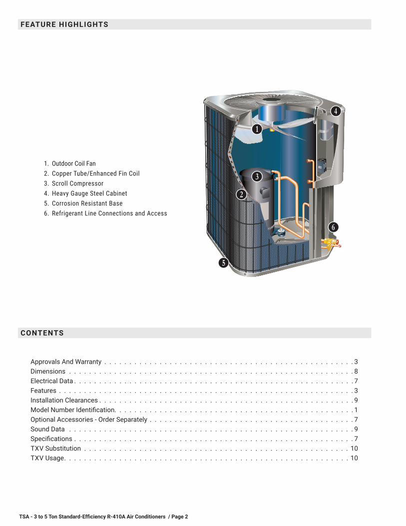
FEATURE HIGHLIGHTS
1. Outdoor Coil Fan2. Copper Tube/Enhanced Fin Coil3. Scroll Compressor4. Heavy Gauge Steel Cabinet5. Corrosion Resistant Base6. Refrigerant Line Connections and Access
CONTENTS
BB
CC
FF
EE
DD
Approvals And Warranty . . . . . . . . . . . . . . . . . . . . . . . . . . . . . . . . . . . . . . . . . . . . . . . . . . 3Dimensions . . . . . . . . . . . . . . . . . . . . . . . . . . . . . . . . . . . . . . . . . . . . . . . . . . . . . . . . . 8Electrical Data . . . . . . . . . . . . . . . . . . . . . . . . . . . . . . . . . . . . . . . . . . . . . . . . . . . . . . . . 7Features . . . . . . . . . . . . . . . . . . . . . . . . . . . . . . . . . . . . . . . . . . . . . . . . . . . . . . . . . . . 3Installation Clearances . . . . . . . . . . . . . . . . . . . . . . . . . . . . . . . . . . . . . . . . . . . . . . . . . . . 9Model Number Identification. . . . . . . . . . . . . . . . . . . . . . . . . . . . . . . . . . . . . . . . . . . . . . . . 1Optional Accessories - Order Separately . . . . . . . . . . . . . . . . . . . . . . . . . . . . . . . . . . . . . . . . . 7Sound Data . . . . . . . . . . . . . . . . . . . . . . . . . . . . . . . . . . . . . . . . . . . . . . . . . . . . . . . . . 9Specifications . . . . . . . . . . . . . . . . . . . . . . . . . . . . . . . . . . . . . . . . . . . . . . . . . . . . . . . . 7TXV Substitution . . . . . . . . . . . . . . . . . . . . . . . . . . . . . . . . . . . . . . . . . . . . . . . . . . . . . 10TXV Usage. . . . . . . . . . . . . . . . . . . . . . . . . . . . . . . . . . . . . . . . . . . . . . . . . . . . . . . . . 10
GG
TSA - 3 to 5 Ton Standard-Efficiency R-410A Air Conditioners / Page 3
APPLICATIONS• 3 through 5 tons• Three-phase power supply• Sound levels as low as 76 dBA• Vertical air discharge• Applicable to indoor air handlers or gas furnaces with
indoor add-on coils• Shipped completely factory assembled, piped and wired• Factory test operated
REFRIGERATION SYSTEM
R-410A Refrigerant• Non-chlorine, ozone friendly• Unit is factory pre-charged
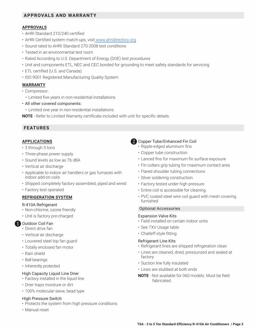
Outdoor Coil Fan• Direct drive fan• Vertical air discharge• Louvered steel top fan guard• Totally enclosed fan motor• Rain shield• Ball bearings• Inherently protected
High Capacity Liquid Line Drier• Factory installed in the liquid line• Drier traps moisture or dirt• 100% molecular-sieve, bead type
High Pressure Switch• Protects the system from high pressure conditions• Manual reset
BB
Copper Tube/Enhanced Fin Coil• Ripple-edged aluminum fins• Copper tube construction• Lanced fins for maximum fin surface exposure• Fin collars grip tubing for maximum contact area• Flared shoulder tubing connections• Silver soldering construction.• Factory tested under high pressure• Entire coil is accessible for cleaning.• PVC coated steel wire coil guard with mesh covering
furnished
Optional Accessories
Expansion Valve Kits• Field installed on certain indoor units• See TXV Usage table• Chatleff-style fitting
Refrigerant Line Kits• Refrigerant lines are shipped refrigeration clean• Lines are cleaned, dried, pressurized and sealed at
factory• Suction line fully insulated• Lines are stubbed at both endsNOTE - Not available for 060 models. Must be field
fabricated.
CC
APPROVALS AND WARRANTY
FEATURES
APPROVALS• AHRI Standard 210/240 certified• AHRI Certified system match-ups, visit www.ahridirectory.org• Sound rated to AHRI Standard 270-2008 test conditions• Tested in an environmental test room• Rated According to U.S. Department of Energy (DOE) test procedures• Unit and components ETL, NEC and CEC bonded for grounding to meet safety standards for servicing• ETL certified (U.S. and Canada)• ISO 9001 Registered Manufacturing Quality System
WARRANTY• Compressor:
• Limited five years in non-residential installations• All other covered components:
• Limited one year in non-residential installationsNOTE - Refer to Limited Warranty certificate included with unit for specific details.

TSA - 3 to 5 Ton Standard-Efficiency R-410A Air Conditioners / Page 4
COMPRESSOR
Scroll Compressor• High efficiency with uniform
suction flow• Constant discharge flow, high
volumetric efficiency and quiet operation
• Low gas pulses during compression reduces operational sound levels
• Compressor motor is internally protected from excessive current and temperature
• Muffler in discharge line reduces operating sound levels
• Compressor is installed in the unit on resilient rubber mounts for vibration free operation
Scroll Compressor Operation• Two involute spiral scrolls matched together generate a
series of crescent-shaped gas pockets between them• During compression, one scroll remains stationary while
the other scroll orbits around it• Gas is drawn into the outer pocket, the pocket is sealed
as the scroll rotates• As the spiral movement continues, gas pockets are
pushed to the center of the scrolls. Volume between the pockets is simultaneously reduced
• When the pocket reaches the center, gas is now at high pressure and is forced out of a port located in the center of the fixed scrolls
• During compression, several pockets are compressed simultaneously resulting in a smooth continuous compression cycle
• Continuous flank contact, maintained by centrifugal force, minimizes gas leakage and maximizes efficiency
• Compressor is tolerant to the effects of slugging and contaminants. If this occurs, scrolls separate, allowing liquid or contaminants to be worked toward the center and discharged
Compressor Crankcase Heater• Protects against refrigerant migration that can occur
during low ambient operation
Optional Accessories
Compressor Sound Cover• A reinforced vinyl compressor cover containing a 1-1/2
inch thick batt of fiberglass insulation.• All open edges are sealed with a one-inch wide hook and
loop fastening tape.
DD
CABINET• Heavy gauge steel cabinet• Five station metal wash process• Powder paint finish for superior rust and corrosion
protection• Control box is conveniently located with all controls
factory wired• Corner patch plate allows compressor access• Drainage holes provided in base section
Unit Base• Durable zinc-coated base section resists rust and
corrosion
Refrigerant Line Connections, Electrical Inlets, Service Valves• Sweat connection suction and liquid lines• Located on corner of unit cabinet• Suction valve can be fully shut off, while liquid valve
may be front seated to manage refrigerant charge while servicing system
• Refrigerant line connections and field wiring inlets are located in one central area of cabinet for easy access
• See dimension drawing
Optional Accessories
Hail Guards• Heavy-gauge steel construction• Painted to match cabinet• Surrounds unit on all four sides• Prevent damage to the coil
Unit Stand-Off Kit• Black high density polyethylene feet• Raises unit off mounting surface• Four feet furnished per order number
EE
GG
FEATURES
TSA - 3 to 5 Ton Standard-Efficiency R-410A Air Conditioners / Page 5
FEATURES
CONTROLS
Optional Accessories
Compressor Low Ambient Cut-Off Switch• Non-adjustable switch (low ambient cut-out)• Prevents compressor operation when outdoor
temperature is below 35°F
Compressor Time-Off Control• Kit prevents compressor short-cycling• Allows time for suction and discharge pressure to
equalize• Permits compressor start-up in an unloaded condition• Automatic reset• Five minute delay between compressor shut-off and
start-up
Indoor Blower Off Delay Relay Kit• Delays indoor blower-off time during the cooling cycle
Low Ambient Kit• Heat pump can operate in the cooling mode down to
45°F outdoor air temperature without additional controls• Two low ambient control options are available for field
installation:1. Low Ambient Control Kit (30°F)2. Low Ambient Control (0°F)
Requires Speed Control and Weatherproof Kit (ordered separately). Available for 208/230V models only.
NOTE - Freezestat should be installed on compressors equipped with a low ambient kit.
Freezestat• Installs on or near the vapor line of the indoor coil or on
the suction line• Senses suction line temperature and cycles the
compressor off when suction line temperature falls below it’s setpoint
• Opens at 29°F and closes at 58°F
Thermostat• For thermostat options, see Optional Conventional
Temperature Control Systems on page 6
TSA - 3 to 5 Ton Standard-Efficiency R-410A Air Conditioners / Page 6
THIS PAGE INTENTIONALLY LEFT BLANK
TSA - 3 to 5 Ton Standard-Efficiency R-410A Air Conditioners / Page 7
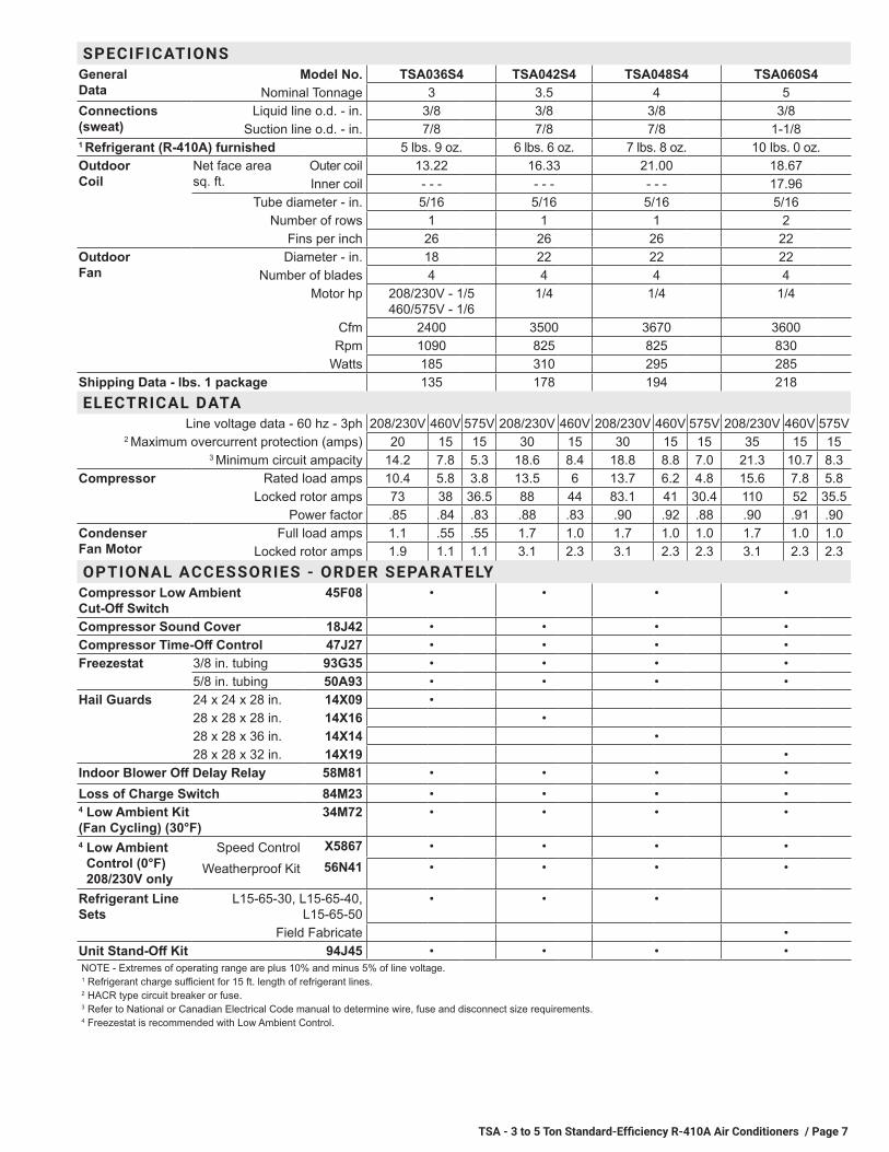
SPECIFICATIONSGeneral Data
Model No. TSA036S4 TSA042S4 TSA048S4 TSA060S4Nominal Tonnage 3 3.5 4 5
Connections (sweat)
Liquid line o.d. - in. 3/8 3/8 3/8 3/8Suction line o.d. - in. 7/8 7/8 7/8 1-1/8
1 Refrigerant (R-410A) furnished 5 lbs. 9 oz. 6 lbs. 6 oz. 7 lbs. 8 oz. 10 lbs. 0 oz.Outdoor Coil
Net face area sq. ft.
Outer coil 13.22 16.33 21.00 18.67Inner coil - - - - - - - - - 17.96
Tube diameter - in. 5/16 5/16 5/16 5/16Number of rows 1 1 1 2
Fins per inch 26 26 26 22Outdoor Fan
Diameter - in. 18 22 22 22Number of blades 4 4 4 4
Motor hp 208/230V - 1/5 460/575V - 1/6
1/4 1/4 1/4
Cfm 2400 3500 3670 3600Rpm 1090 825 825 830
Watts 185 310 295 285Shipping Data - lbs. 1 package 135 178 194 218ELECTRICAL DATA
Line voltage data - 60 hz - 3ph 208/230V 460V 575V 208/230V 460V 208/230V 460V 575V 208/230V 460V 575V2 Maximum overcurrent protection (amps) 20 15 15 30 15 30 15 15 35 15 15
3 Minimum circuit ampacity 14.2 7.8 5.3 18.6 8.4 18.8 8.8 7.0 21.3 10.7 8.3Compressor Rated load amps 10.4 5.8 3.8 13.5 6 13.7 6.2 4.8 15.6 7.8 5.8
Locked rotor amps 73 38 36.5 88 44 83.1 41 30.4 110 52 35.5Power factor .85 .84 .83 .88 .83 .90 .92 .88 .90 .91 .90
Condenser Fan Motor
Full load amps 1.1 .55 .55 1.7 1.0 1.7 1.0 1.0 1.7 1.0 1.0Locked rotor amps 1.9 1.1 1.1 3.1 2.3 3.1 2.3 2.3 3.1 2.3 2.3
OPTIONAL ACCESSORIES - ORDER SEPARATELYCompressor Low Ambient Cut-Off Switch
45F08 • • • •
Compressor Sound Cover 18J42 • • • •Compressor Time-Off Control 47J27 • • • •Freezestat 3/8 in. tubing 93G35 • • • •
5/8 in. tubing 50A93 • • • •Hail Guards 24 x 24 x 28 in. 14X09 •
28 x 28 x 28 in. 14X16 •28 x 28 x 36 in. 14X14 •28 x 28 x 32 in. 14X19 •
Indoor Blower Off Delay Relay 58M81 • • • •Loss of Charge Switch 84M23 • • • •4 Low Ambient Kit (Fan Cycling) (30°F)
34M72 • • • •
4 Low Ambient Control (0°F) 208/230V only
Speed Control X5867 • • • •
Weatherproof Kit 56N41 • • • •
Refrigerant Line Sets
L15-65-30, L15-65-40, L15-65-50
• • •
Field Fabricate •Unit Stand-Off Kit 94J45 • • • •NOTE - Extremes of operating range are plus 10% and minus 5% of line voltage.1 Refrigerant charge sufficient for 15 ft. length of refrigerant lines.2 HACR type circuit breaker or fuse.3 Refer to National or Canadian Electrical Code manual to determine wire, fuse and disconnect size requirements.4 Freezestat is recommended with Low Ambient Control.

TSA - 3 to 5 Ton Standard-Efficiency R-410A Air Conditioners / Page 8
SIDE VIEW
SUCTION &LIQUID LINE
CONNECTIONS
INLET
AIR
INLET
AIR
DISCHARGE AIR
SIDE VIEW
TOP VIEW
CONDENSERCOIL FAN
COMPRESSOR
INLET AIR
INLET AIR
SUCTION LINECONNECTION
2-3/4 (70)
A
ELECTRICALINLETS
LIQUID LINECONNECTION
6-3/8(162)
TOP VIEW BASE SECTION
COMPRESSOR
COIL DRAIN OUTLETS(Around perimeter of base)
OPTIONAL UNITSTAND-OFF KIT (4)
(Field Installed)
B
A
OPTIONAL UNITSTAND-OFF KIT (4)
(Field Installed)
2 (51)
3/4(19)
4-3/8(111)
4-3/8(111)
4-3/8(111)
4-3/8(111)
4-3/8(111)
4-3/8(111)
6-3/8(162)
C
DIMENSIONS
Model No.A B C
inches mm inches mm inches mmTSA036S4 24-1/4 616 29-1/4 743 28-1/2 724TSA042S4 28-1/4 718 29-1/4 743 28-1/2 724TSA048S4 28-1/4 718 37-1/4 946 36-1/2 927TSA060S4 28-1/4 718 33-1/4 845 32-1/2 826

TSA - 3 to 5 Ton Standard-Efficiency R-410A Air Conditioners / Page 9
SeeNOTES
See NOTES
See NOTES
SeeNOTES
CONTROLBOX
NOTES:Service clearance of 30 in. (762 mm) must be maintained on
one of the sides adjacent to the control box.Clearance to one of the other three sides must be 36 in.
(914 mm)Clearance to one of the remaining two sides may be 12 in.
(305 mm) and the final side may be 6 in. (152 mm).A clearance of 24 in. must be maintained between two units.48 in. (1219 mm) clearance required on top of unit.
INSTALLATION CLEARANCES
SOUND DATA
1 Unit Model
Octave Band Sound Power Levels dBA, re 10-12 Watts Center Frequency - HZ
1 Sound Rating
Number (dBA)
² Estimated Sound Pressure Level at Distance From Unit (dBA at distance in ft.)
125 250 500 1000 2000 4000 8000 3 5 10 15 50
TSA036S4 70.5 67.5 69.5 72.5 69.5 63 59 76 69 64 58 55 44TSA042S4 74 76.5 76.5 75.5 72 68 63.5 80 73 68 62 59 48TSA048S4 73.5 76 76 76.5 72.5 69.5 64.5 80 73 68 62 59 48TSA060S4 73.5 74.5 77 75 72 69 64.5 80 73 68 62 59 48
NOTE - the octave sound power data does not include tonal correction.1 Tested according to AHRI Standard 270-2008 test conditions.2 Estimated sound pressure level at distance based on AHRI Standard 275-2010 method for equipment located on the ground, roof, or on side of building wall with no
adjacent reflective surface within 9.8 feet. Sound pressure levels will increase based on changes to assumptions. For other applications, refer to AHRI Standard 275.
TSA - 3 to 5 Ton Standard-Efficiency R-410A Air Conditioners / Page 10
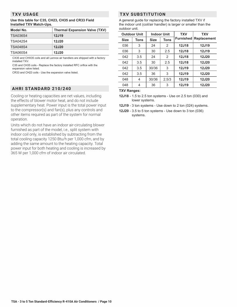
TXV USAGEUse this table for C35, CH23, CH35 and CR33 Field Installed TXV Match-Ups.Model No. Thermal Expansion Valve (TXV)TSA036S4 12J19TSA042S4 12J20TSA048S4 12J20TSA060S4 12J20
CX35 and CHX35 coils and all Lennox air handlers are shipped with a factory installed TXV.C35 and CH35 coils - Replace the factory installed RFC orifice with the expansion valve listed.CR33 and CH23 coils - Use the expansion valve listed.
AHRI STANDARD 210/240
Cooling or heating capacities are net values, including the effects of blower motor heat, and do not include supplementary heat. Power input is the total power input to the compressor(s) and fan(s), plus any controls and other items required as part of the system for normal operation.Units which do not have an indoor air-circulating blower furnished as part of the model, i.e., split system with indoor coil only, is established by subtracting from the total cooling capacity 1250 Btu/h per 1,000 cfm, and by adding the same amount to the heating capacity. Total power input for both heating and cooling is increased by 365 W per 1,000 cfm of indoor air circulated.
TXV SUBSTITUTIONA general guide for replacing the factory installed TXV if the indoor unit (coil/air handler) is larger or smaller than the outdoor unit.
Outdoor Unit Indoor Unit TXV Furnished
TXV ReplacementSize Tons Size Tons
036 3 24 2 12J18 12J19036 3 30 2.5 12J18 12J19042 3.5 24 2 12J18 12J20042 3.5 30 2.5 12J18 12J20042 3.5 30/36 3 12J19 12J20042 3.5 36 3 12J19 12J20048 4 30/36 2.5/3 12J19 12J20048 4 36 3 12J19 12J20
TXV Ranges:12J18 - 1.5 to 2.5 ton systems - Use on 2.5 ton (030) and
lower systems.12J19 - 3 ton systems - Use down to 2 ton (024) systems.12J20 - 3.5 to 5 ton systems - Use down to 3 ton (036)
systems.


REVISIONS
REVISIONS
Sections Description of Change
TXV Substitution Updated.
Visit us at www.allied-commercial.com For the latest technical information, visit us at www.allied-commercial.com Contact us at 1-800-448-5872
NOTE - Due to Allied Commercial ongoing commitment to quality, Specifications, Ratings and Dimensions subject to change without notice and without incurring liability. Improper installation, adjustment, alteration, service or maintenance can cause property damage or personal injury. Installation and service must be performed by a qualified installer and servicing agency.
©2019 Allied Air Enterprises LLC, a International Inc. Company