ts4000 user's manual - teledesign systemsteledesignsystems.com/downloads/ts4000/ts4000 manual...
TRANSCRIPT

TS4000 Radio Modem
User’s Manual
Version 6.40
1729 South Main Street
Milpitas, CA 95035
(408) 941-1808 (800) 663-3674
(408) 941-1818 Fax
www.teledesignsystems.com
This document is copyrighted by Teledesign Systems Inc. with all rights reserved. No part of this document may be reproduced in any form without the prior written consent of Teledesign Systems Inc.
Copyright
Copyright © 1995 - 2012 by Teledesign Systems Inc. All rights reserved. This manual has been thoroughly reviewed for accuracy, and every effort has been made to ensure that the information is accurate and complete. However, different versions of this product have different features and capabilities, and this manual reflects only one of those versions. Therefore, Teledesign Systems Inc. assumes no responsibility for errors, omissions or defects in this material, and shall not be liable for any damages resulting from their use.
Disclaimer
The information in this document is subject to change without notice. TELEDESIGN SYSTEMS INC. MAKES NO WARRANTY OF ANY KIND WITH RESPECT TO THIS DOCUMENT AND SOFTWARE, EITHER EXPRESSED OR IMPLIED, INCLUDING WITHOUT LIMITATION ANY IMPLIED WARRANTIES OF MERCHANTABILITY OR FITNESS FOR A PARTICULAR PURPOSE.

Emissions FCC The TS4000 complies with Part 15 of the FCC Rules (Code of Federal Regulations 47CFR Part 15). Operation is subject to the following two conditions: (1) This device does not cause harmful interference, and (2) this device must accept any interference received, including interference that may cause undesired operation.
Part 15
The TS4000 has been type accepted for operation by the FCC in accordance with Part 90 of the FCC rules (47CFR Part 90). See the label on the unit for the specific FCC ID and any other certification designations.
Part 90
The TS4000 has been type accepted for operation by the FCC in accordance with Part 101 of the FCC rules (47CFR Part 101). See the label on the unit for the specific FCC ID and any other certification designations.
Part 101
Industry Canada This Class B digital apparatus meets all requirements of the Canadian Interference-Causing Equipment Regulations.
ICES-003
The TS4000 has been certified for operation by Industry Canada in accordance with RSS-119 and RSS-210 of the Industry Canada rules. See the label on the unit for the specific Industry Canada certification number and any other certification designations.
RSS-119
Changes or modifications not expressly approved by Teledesign Systems Inc. could void the user’s authority to operate this equipment. Notice Shielded cable must be used with this equipment in order to ensure that it meets the emissions limits for which it was designed. It is the responsibility of the user to obtain and use good quality shielded cables with this device. Shielded cables are available from most retail and commercial suppliers of cables designed to work with radio equipment and personal computer peripherals. The frequency band from 406.0 to 406.1 MHz is reserved for use by distress beacons. As such, the TS4000 should not be programmed to transmit on any frequency within this band. Caution should be used when programming frequencies into the TS4000 to eliminate the possibility of TS4000 users interfering with rescue operations on this band.
406.0 to 406.1 MHz Operation
In order to ensure the safe operation of this radio equipment, the following practices should be observed. Safety Warning • DO NOT operate radio equipment near electrical blasting caps or in an
explosive atmosphere. • DO NOT operate any radio transmitter unless all RF connectors are secure
and any open connectors are properly terminated. • DO NOT allow the antenna to come close to, or touch, the eyes, face, or any
exposed body parts while the radio is transmitting.
TS4000 Radio Modem User’s Manual Emissions iii
In order to ensure the safe operation of this radio equipment, the minimum distance that a person should be from the attached antenna when this equipment is transmitting is 5.5 ft. (165 cm). This is based on using the TS4000 at a power of 5 watts with a 10dBd (12.1dbi) gain antenna.
RF Exposure
TS4000 Radio Modem User’s Manual Emissions iv
Table of Contents
Emissions ......................................................................................................iii FCC.................................................................................................... iii Industry Canada................................................................................. iii
Notice.......................................................................................................iii 406.0 to 406.1 MHz Operation ...............................................................iii Safety Warning .......................................................................................iii RF Exposure ...........................................................................................iv
Table of Contents...........................................................................................v
TS4000 Overview ...........................................................................................1 Introduction..............................................................................................1 Features....................................................................................................1 Model Numbers........................................................................................3 Radio Modules.........................................................................................3
Frequency Bands................................................................................4 Transmit Power...................................................................................4 Channel Spacing and Bandwidth........................................................4
Enclosure .................................................................................................5 Standard .............................................................................................5 Watertight............................................................................................5
Connections.............................................................................................5 Serial Port ...........................................................................................5 Antenna Connector .............................................................................5 Power Connection...............................................................................5
Mounting ..................................................................................................6 Configuring the TS4000 ..........................................................................6 AirTest - Data Testing .............................................................................6 Upgrading the TS4000 Firmware ...........................................................7 AirScan .....................................................................................................7 Remote Diagnostics................................................................................7 AirCalc - Range Estimation ....................................................................7 Status Lights............................................................................................8
Configuration Program..................................................................................9 Using Help................................................................................................9 System Requirements.............................................................................9 Installation................................................................................................9 TS4000 to PC Connection.......................................................................9 Programming and Retrieving Configurations ....................................10 Storing Configurations .........................................................................10 Diagnostics ............................................................................................11
Diagnostics Screen...........................................................................11 Modem Hardware Screen.................................................................12 Radio Hardware Screen ...................................................................12
Serial Port .....................................................................................................13 RS-232 Serial Port Basics.....................................................................13
Connectors........................................................................................13 DCE vs. DTE.....................................................................................13 Asynchronous Data ..........................................................................13 Flow Control......................................................................................13
Serial Port Connector ...........................................................................14
TS4000 Radio Modem User’s Manual Table of Contents v
Signal Levels..........................................................................................14 Signal Options .......................................................................................14
RI Pin Signal Options........................................................................15 DSR Pin Signal Options....................................................................15 DTR Pin Signal Options....................................................................15
Configuration Options – Serial Port 1 .................................................16 Serial Port 2............................................................................................20
Radio Setup ..................................................................................................23 Configuration Options ..........................................................................23
Clear Channel Scan..........................................................................25 Redundancy......................................................................................25
Frequency Programming......................................................................28 406.0 to 406.1 MHz Operation..........................................................28 Methods of Programming Channels .................................................28 Frequency Configuration Screen......................................................29
Channel Switching ................................................................................30 Channel Change with a Control String .............................................30
Compatibility..........................................................................................31
AirNet Packet Protocol ................................................................................33 Overview.................................................................................................33 Configuration Options ..........................................................................35
Packet General .................................................................................35 Packet for Port 1 / Packet for Port 2 .................................................38
Control and Status Strings...................................................................42 Control Strings ..................................................................................42 Status Strings....................................................................................43
Master-Slave System Setup .................................................................44 Setting Packet Timeout.....................................................................44 Data Packet Transmit Time ..............................................................45
Polled System with Store and Forward Repeaters............................46 Single Repeater System ...................................................................47 Dual Repeater System......................................................................49 Three Repeater System....................................................................51 Chain Repeater System....................................................................54 Other System Topologies .................................................................56
CSMA System Setup .............................................................................57 Basic System - Setup Summary .......................................................57 System with Repeaters - Setup Summary........................................58 Setting Slot Time...............................................................................60 Setting Min Idle Slots ........................................................................60 Setting Tx Index ................................................................................61 Setting Packet Timeout.....................................................................63 Data Packet Delay ............................................................................64
GPS Configuration.......................................................................................66 Configuration Options ..........................................................................66
Testing ..........................................................................................................69 AirTest ....................................................................................................69
Data Test ..........................................................................................69 BER Test...........................................................................................70
AirScan ...................................................................................................71 AirScan Controls ...............................................................................71
Remote Diagnostics ....................................................................................72
TS4000 Radio Modem User’s Manual Table of Contents vi

Remote Diagnostics with Repeaters ................................................72 Remote Diagnostics Screen .............................................................72 Remote Diagnostic Controls .............................................................72 Remote Diagnostics Request and Response Strings ......................74
Upgrading Firmware....................................................................................75 Upgrading...............................................................................................75
Licensing ......................................................................................................76 User’s License .......................................................................................76
Channel Spacing and Occupied Bandwidth .....................................76 USA (FCC)........................................................................................77 International ......................................................................................77
Unlicensed Operation ...........................................................................77 Frequencies and Channel Bandwidth...............................................77 Power................................................................................................78
Manufacturer’s Certification ................................................................78 USA (FCC)........................................................................................78 Industry Canada................................................................................79 International ......................................................................................79
Service and Support ....................................................................................80 Contacting Teledesign..........................................................................80 Returning Equipment............................................................................80
Warranty........................................................................................................81
Appendix A - Serial Ports............................................................................82 Standard Case .......................................................................................82
Serial Port 1 Pinout ...........................................................................82 Serial Port 2 Pinout ...........................................................................82
Watertight Case .....................................................................................82 Pinout ................................................................................................82
Standard RS-232 Serial Port Pinout ....................................................84 Standard Usage of the RS-232 Control Signals .................................84 Signal Levels..........................................................................................85
Appendix B – ASCII Character Set.............................................................86
Appendix C - Specifications .......................................................................87 General ...................................................................................................87 Specifications: TS4000-02A .................................................................88 Specifications: TS4000-05B .................................................................89 Specifications: TS4000-05C .................................................................90 Specifications: TS4000-05D .................................................................91 Specifications: TS4000-05E..................................................................92 Specifications: TS4000-05F..................................................................93
Appendix D - Case Dimensions..................................................................94
Appendix E – Control and Status Strings .................................................96 General Strings .................................................................................96 Frequency Control Strings ................................................................96 Modem Configuration Strings ...........................................................96 Packet Strings...................................................................................97 Diagnostics Strings ...........................................................................99
TS4000 Radio Modem User’s Manual Table of Contents vii

Appendix F – Internal Jumper Block .......................................................102 Factory Default Jumper Settings ....................................................102 Instructions for Accessing the Jumpers..........................................102 Jumper Settings for Power on Serial Port 1 - Pin 9 ........................103 Jumper Settings for Power on Serial Port 1 - Pin 4 ........................103 Jumper Settings for Power on Serial Port 2 - Pin 9 ........................104 Jumper Settings for TTL Levels on Serial Port 1............................104
Appendix G – FCC MURS Rules...............................................................105
TS4000 Radio Modem User’s Manual Table of Contents viii
TS4000 Radio Modem User’s Manual TS4000 Overview 1
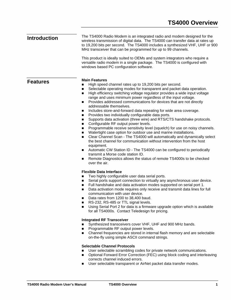
TS4000 Overview The TS4000 Radio Modem is an integrated radio and modem designed for the wireless transmission of digital data. The TS4000 can transfer data at rates up to 19,200 bits per second. The TS4000 includes a synthesized VHF, UHF or 900 MHz transceiver that can be programmed for up to 99 channels.
Introduction
This product is ideally suited to OEMs and system integrators who require a versatile radio modem in a single package. The TS4000 is configured with windows based PC configuration software. Main Features Features
High speed channel rates up to 19,200 bits per second. Selectable operating modes for transparent and packet data operation. High efficiency switching voltage regulator provides a wide input voltage
range and uses minimum power regardless of the input voltage. Provides addressed communications for devices that are not directly
addressable themselves. Includes store-and-forward data repeating for wide area coverage. Provides two individually configurable data ports. Supports data activation (three wire) and RTS/CTS handshake protocols. Configurable RF output power levels. Programmable receive sensitivity level (squelch) for use on noisy channels. Watertight case option for outdoor use and marine installations. Clear Channel Scan - The TS4000 will automatically and dynamically select
the best channel for communication without intervention from the host equipment.
Automatic CW Station ID - The TS4000 can be configured to periodically transmit a Morse code station ID.
Remote Diagnostics allows the status of remote TS4000s to be checked over the air.
Flexible Data Interface
Two highly configurable user data serial ports. Serial ports support connection to virtually any asynchronous user device. Full handshake and data activation modes supported on serial port 1. Data activation mode requires only receive and transmit data lines for full
communication with user device. Data rates from 1200 to 38,400 baud. RS-232, RS-485 or TTL signal levels. Using Serial Port 2 for data is a firmware upgrade option which is available
for all TS4000s. Contact Teledesign for pricing. Integrated RF Transceiver
Synthesized transceivers cover VHF, UHF and 900 MHz bands. Programmable RF output power levels. Channel frequencies are stored in internal flash memory and are selectable
on-the-fly using simple ASCII command strings. Selectable Channel Protocols
User selectable scrambling codes for private network communications. Optional Forward Error Correction (FEC) using block coding and interleaving
corrects channel induced errors. User selectable transparent or AirNet packet data transfer modes.
TS4000 Radio Modem User’s Manual TS4000 Overview 2
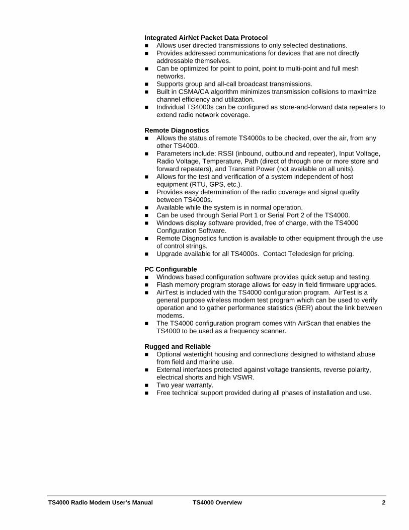
Integrated AirNet Packet Data Protocol Allows user directed transmissions to only selected destinations. Provides addressed communications for devices that are not directly
addressable themselves. Can be optimized for point to point, point to multi-point and full mesh
networks. Supports group and all-call broadcast transmissions. Built in CSMA/CA algorithm minimizes transmission collisions to maximize
channel efficiency and utilization. Individual TS4000s can be configured as store-and-forward data repeaters to
extend radio network coverage. Remote Diagnostics
Allows the status of remote TS4000s to be checked, over the air, from any other TS4000.
Parameters include: RSSI (inbound, outbound and repeater), Input Voltage, Radio Voltage, Temperature, Path (direct of through one or more store and forward repeaters), and Transmit Power (not available on all units).
Allows for the test and verification of a system independent of host equipment (RTU, GPS, etc,).
Provides easy determination of the radio coverage and signal quality between TS4000s.
Available while the system is in normal operation. Can be used through Serial Port 1 or Serial Port 2 of the TS4000. Windows display software provided, free of charge, with the TS4000
Configuration Software. Remote Diagnostics function is available to other equipment through the use
of control strings. Upgrade available for all TS4000s. Contact Teledesign for pricing.
PC Configurable
Windows based configuration software provides quick setup and testing. Flash memory program storage allows for easy in field firmware upgrades. AirTest is included with the TS4000 configuration program. AirTest is a
general purpose wireless modem test program which can be used to verify operation and to gather performance statistics (BER) about the link between modems.
The TS4000 configuration program comes with AirScan that enables the TS4000 to be used as a frequency scanner.
Rugged and Reliable
Optional watertight housing and connections designed to withstand abuse from field and marine use.
External interfaces protected against voltage transients, reverse polarity, electrical shorts and high VSWR.
Two year warranty. Free technical support provided during all phases of installation and use.
TS4000 Radio Modem User’s Manual TS4000 Overview 3
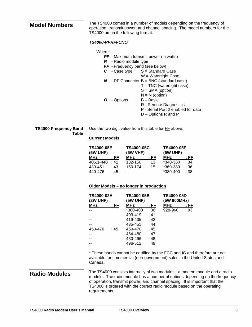
The TS4000 comes in a number of models depending on the frequency of operation, transmit power, and channel spacing. The model numbers for the TS4000 are in the following format.
Model Numbers
TS4000-PPRFFCNO Where: PP - Maximum transmit power (in watts) R - Radio module type
FF - Frequency band (see below) C - Case type: S = Standard Case W = Watertight Case N - RF Connector: B = BNC (standard case) T = TNC (watertight case) S = SMA (option) N = N (option) O - Options B – Basic R - Remote Diagnostics P - Serial Port 2 enabled for data D – Options R and P
Use the two digit value from this table for FF above. TS4000 Frequency Band
Table Current Models TS4000-05E TS4000-05C TS4000-05F (5W UHF) (5W VHF) (5W UHF) MHz : FF MHz : FF MHz : FF 406.1-440 : 41 132-150 : 13 *340-360 : 34 430-451 : 43 150-174 : 15 *360-380 : 36 440-476 : 45 -- *380-400 : 38 Older Models – no longer in production TS4000-02A TS4000-05B TS4000-05D (2W UHF) (5W UHF) (5W 900MHz) MHz : FF MHz : FF MHz : FF -- *380-403 : 38 928-960 : 93 -- 403-419 : 41 -- -- 419-435 : 42 -- 435-451 : 44 450-470 : 45 450-470 : 45 -- 464-480 : 47 -- 480-496 : 48 -- 496-512 : 49 * These bands cannot be certified by the FCC and IC and therefore are not available for commercial (non-government) sales in the United States and Canada. The TS4000 consists internally of two modules - a modem module and a radio module. The radio module has a number of options depending on the frequency of operation, transmit power, and channel spacing. It is important that the TS4000 is ordered with the correct radio module based on the operating requirements.
Radio Modules
TS4000 Radio Modem User’s Manual TS4000 Overview 4
The radio module of the TS4000 comes in various frequency bands including VHF, UHF and 900 MHz. Within each of these bands, there are sub-bands that define the specific frequency range over which a particular radio module will operate (i.e. 450 to 470 MHz).
Frequency Bands
For some of the frequency bands, there several options for the radio module transmit power. The most common transmit power levels available are 2 watts and 5 watts. The transmit power can be reduced from the maximum power with the transmit power level setting control (See Radio Setup).
Transmit Power
The transmit power of the radio module effects the maximum transmit duty cycle that the TS4000 can be operated with. Transmit duty cycle is the percentage of time that the modem is transmitting (i.e. 50 %). If the TS4000 is operated with too high a transmit duty cycle, then the radio module may get too hot which can result in damage. The maximum safe transmit duty can be increased by reducing the maximum environmental temperature, adding a heat sink to the back plate of the TS4000, or reducing the transmit output power output.
Transmit Duty Cycle
If more transmit power is desired than the internal TS4000 radio module can provide then an external power amplifier can be used to boost the power. For connection to the TS4000 it is important that the power amplifier have automatic power sensing to switch between receive and transmit modes. It is also important that the power amplifier has fast power switching so that the TS4000 transmit attack time (amount of time to initiate a transmission) does not have to increased excessively.
Power Amplifiers
For some frequency bands, there are multiple options for the radio module channel spacing and bandwidth.
Channel Spacing and Bandwidth
The channel spacing defines how close together the channels are within a band (i.e. 12.5 kHz). To use channels with a particular channel spacing, the radio module’s frequency synthesizer must be programmable to multiples or sub-multiples of the channel spacing. The TS4000 radio module should be ordered based on the channel spacing of the channels to be used.
Channel Spacing
The channel bandwidth is the amount of frequency spectrum that the radio transmit signal is allowed to occupy (i.e. 16 kHz). This bandwidth must be controlled in order to minimize the interference between users on adjacent channels.
Channel Bandwidth
For the TS4000, the data rate and the type of modulation control the transmitted channel bandwidth. Therefore, it is important that the TS4000 is setup so that its transmitted bandwidth is less than that prescribed for the channels being used (See Radio Setup, Licensing).
Transmit Channel Bandwidth
The receive filters of the TS4000 radio module are designed for a specific channel bandwidth. The radio module should be ordered with a receive filter bandwidth that matches the bandwidth of the channels used.
Receive Channel Bandwidth
Note that if multiple channel bandwidths are to be used, then the radio module should be ordered for the channel with the highest channel bandwidth. This may result in less than optimal performance on channels with narrower channel bandwidths.
TS4000 Radio Modem User’s Manual TS4000 Overview 5
The TS4000 is available in either a standard or watertight enclosure (see Appendix D - Case Dimensions). Enclosure The standard enclosure has four external connectors - an antenna connector, a power connector and two serial port connectors.
Standard The watertight enclosure is environmentally sealed and is designed to withstand dust, rain and water splashes.
Watertight Caution: The watertight enclosure should not be submerged in water. The watertight enclosure has two external connectors - an antenna connector and an interface connector that provides the serial port and power connections. The interface connector is a 19 pin LEMO connector. The mating connector for this is a LEMO FGG.2B.319 series connector. Connections The TS4000 has two serial ports that provide a data connection between the TS4000 and the host equipment. The serial ports are standard RS-232 asynchronous serial interfaces and are setup as DCEs. The serial ports provide all the standard RS-232 handshake lines. In addition, the TS4000 provides a number of configuration options that allow the serial port line usage to be customized for different host equipment (see Serial Port Configuration Options).
Serial Port
Serial port 1 can be configured for either RS-232 or TTL signal levels. To change the signal level setting, the modem must be opened and the four jumper plugs next to the serial port connector moved to the desired position (See Appendix A - Serial Port, Appendix F - Internal Jumper Block).
Signal Levels
The serial port connectors are standard 9 pin subminiature D with female pins. These ports can be mated to with standard PC serial cables. To minimize emissions and interference, the serial cables used should be good quality shielded cable (See Appendix A - Serial Port).
Standard Case
The watertight case provides the serial port connections through a single sealed interface connector (See Appendix A - Serial Port).
Watertight Case
A variety of antennas can be used with the TS4000, but it is important that the antenna provides a 50 ohm load at the radio’s operational frequencies. In addition, all cabling used with the antenna must be good quality coaxial cable with 50 ohm impedance.
Antenna Connector
Caution: The modem should never be allowed to transmit without an antenna or dummy load attached to the antenna connector. The standard case comes with a 50 ohm female BNC antenna connector. Standard Case The watertight case comes with a 50 ohm female TNC antenna connector. Watertight Case The TS4000 requires a DC supply voltage between 9 and 28 volts. Note that the minimum supply voltage depends on the particular radio module in the TS4000. In addition, the power (watts) used by the TS4000 also depends on the particular radio module.
Power Connection

TS4000 Radio Modem User’s Manual TS4000 Overview 6
Internally, the TS4000 has a high efficiency switching voltage regulator (as opposed to a linear voltage regulator). The switching regulator minimizes the amount of power that the TS4000 requires. Also, the power required (watts) is independent of the input supply voltage.
Switching Regulator
The power supply current required depends on the input voltage used. This can be calculated with the following formula.
Power Supply Current
Max Power Supply Current (amps) = Max Power (watts) / Input Voltage Max Power = 10 watts (The actual value depends on the particular radio module
in the TS4000). Example
Power Supply Voltage = 20 volts Max Power Supply Current = 10 / 20 = 0.5 amps With the standard case power can be connected through either the power connector or one of the serial port connectors. The power connector is a 2 pin Molex Micro-Fit 3.0 (Molex P/N 43045-0202) with pin 1 as ground and pin 2 as power. The mating plug for this connector is a Molex P/N 43025-0200. See the Serial Port section for details on connecting power through the serial ports.
Standard Case
With the watertight case power is connected through the sealed interface connector.
Watertight Case
The TS4000 has an internal 4 amp fuse for each of the three possible power connections. The power source used with the TS4000 should also be fused with an in-line power fuse.
Fuses
The preferred method of mounting the TS4000 is to use the mounting bracket supplied with the modem. An alternative is to use the threaded mounting holes in the bottom of the TS4000 (see Appendix D - Case Dimensions).
Mounting
The TS4000 is supplied with a windows based PC configuration program. Configuring the TS4000 consists of configuring the modem operating parameters and also configuring the frequency channels. For details on how to load and start the configuration program see Installation in the TS4000 Configuration Program section.
Configuring the TS4000
Making selections with the controls on the various configuration screens sets a configuration. Once set, configurations can be programmed into the TS4000. In addition, configurations can be retrieved from the TS4000. Configurations can also be stored and recalled as PC files. Details about the configuration controls are available later in this manual and in the on line help of the configuration program.
Teledesign provides general-purpose wireless modem test software called AirTest. AirTest can send data and gather performance statistics, including BER (Bit Error Rate), about the link between two modems.
AirTest is accessed with the AirTest button on the main screen of the configuration program (See Testing - AirTest).
AirTest - Data Testing
TS4000 Radio Modem User’s Manual TS4000 Overview 7
The TS4000 comes with flash program memory that allows the firmware to be easily upgraded in the field. Firmware is upgraded with the upgrade program which is included as part of the TS4000 configuration program. The upgrade program is started with the Upgrade Firmware button on the main screen of the configuration program (See Upgrading Firmware).
Upgrading the TS4000 Firmware
AirScan is a program that comes with the TS4000 configuration program and enables the TS4000 to be used as a frequency scanner. AirScan is useful for determining the frequency and magnitude of potential interference within the TS4000’s frequency band. AirScan is started with the AirScan button on the main screen of the configuration program (See Testing - AirScan).
AirScan
Remote diagnostics is used to check the status of remote TS4000s over the air. This allows the radio communication to be setup and tested independent of the host equipment.
Remote Diagnostics
Remote diagnostics is an extra cost firmware option which can be used with any TS4000. The remote diagnostics firmware option upgrade is accomplished the same way as a standard firmware upgrade (see Upgrading Firmware). Please contact Teledesign for ordering information. The remote diagnostics can be accessed using the Remote Diagnostics screen in the TS4000 Configuration Program and can be operated through either serial port. For more details see Remote Diagnostics.
Teledesign provides wireless range estimation software called AirCalc. AirCalc provides estimates of the flat terrain range of wireless data communication systems. Actual range of a system can vary
dramatically, and therefore it is important that range is verified with in field tests in the area of operation. AirCalc is accessed with the AirCalc button on the main screen of the configurati
AirCalc - Range Estimation
on program.
TS4000 Radio Modem User’s Manual TS4000 Overview 8
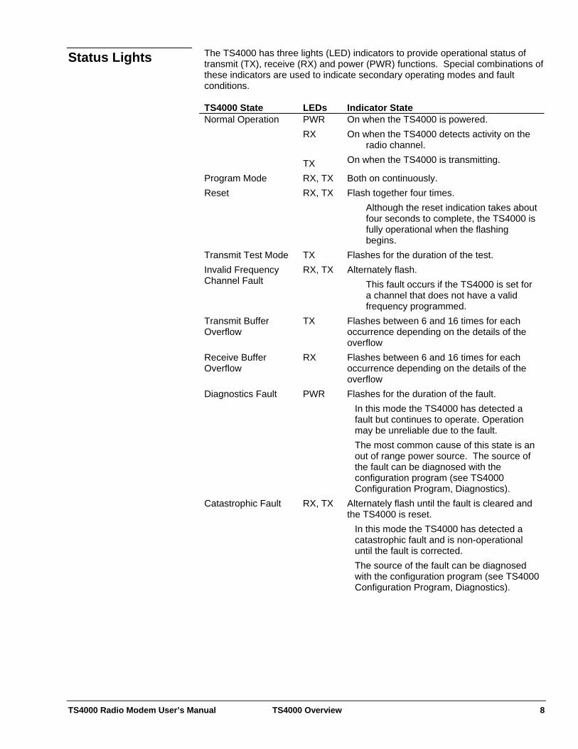
The TS4000 has three lights (LED) indicators to provide operational status of transmit (TX), receive (RX) and power (PWR) functions. Special combinations of these indicators are used to indicate secondary operating modes and fault conditions.
Status Lights
TS4000 State LEDs Indicator State Normal Operation PWR
RX TX
On when the TS4000 is powered. On when the TS4000 detects activity on the
radio channel. On when the TS4000 is transmitting.
Program Mode RX, TX Both on continuously. Reset RX, TX Flash together four times.
Although the reset indication takes about four seconds to complete, the TS4000 is fully operational when the flashing begins.
Transmit Test Mode TX Flashes for the duration of the test. Invalid Frequency Channel Fault
RX, TX Alternately flash. This fault occurs if the TS4000 is set for a channel that does not have a valid frequency programmed.
Transmit Buffer Overflow
TX Flashes between 6 and 16 times for each occurrence depending on the details of the overflow
Receive Buffer Overflow
RX Flashes between 6 and 16 times for each occurrence depending on the details of the overflow
Diagnostics Fault PWR Flashes for the duration of the fault. In this mode the TS4000 has detected a fault but continues to operate. Operation may be unreliable due to the fault. The most common cause of this state is an out of range power source. The source of the fault can be diagnosed with the configuration program (see TS4000 Configuration Program, Diagnostics).
Catastrophic Fault RX, TX Alternately flash until the fault is cleared and the TS4000 is reset.
In this mode the TS4000 has detected a catastrophic fault and is non-operational until the fault is corrected. The source of the fault can be diagnosed with the configuration program (see TS4000 Configuration Program, Diagnostics).
TS4000 Radio Modem User’s Manual Configuration Program 9
Configuration Program The configuration program is used to configure the TS4000 for operation. Configuring the TS4000 consists of independently configuring both the modem operation and the radio frequency channels. The configuration program consists of controls and menus. The controls set the configuration and test options. The menus (line items at the top of the screen) execute program commands. In addition to configuring the TS4000, the configuration program provides access to AirTest (wireless modem test software), AirCalc (wireless range estimation), AirScan (frequency scanning), TS4000 firmware upgrade program (see Testing, Upgrading Firmware) and remote diagnostics (see Remote Diagnostics). The configuration program has on-line help that contains information on how to use the program and also detailed information on specific controls and menus. Help is accessed by selecting a command from the help menu, pressing the question button or pressing the F1 key.
Using Help
Personal computer using a 486 or faster System Requirements
Microsoft Windows 95 or later CD-ROM disk drive.
1) Put the CD-ROM in the PC. Installation 2) Run the installation program. 3) Follow the installation instructions.
Serial Cable TS4000 to PC Connection
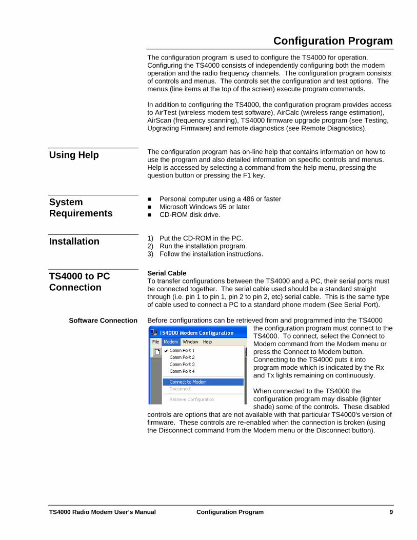
To transfer configurations between the TS4000 and a PC, their serial ports must be connected together. The serial cable used should be a standard straight through (i.e. pin 1 to pin 1, pin 2 to pin 2, etc) serial cable. This is the same type of cable used to connect a PC to a standard phone modem (See Serial Port). Before configurations can be retrieved from and programmed into the TS4000
the configuration program must connect to the TS4000. To connect, select the Connect to Modem command from the Modem menu or press the Connect to Modem button. Connecting to the TS4000 puts it into program mode which is indicated by the Rxand Tx lights remaining on contin
Software Connection
uously.
When connected to the TS4000 the configuration program may disable (lighter shade) some of the controls. These disabled
controls are options that are not available with that particular TS4000's version of firmware. These controls are re-enabled when the connection is broken (using the Disconnect command from the Modem menu or the Disconnect button).
TS4000 Radio Modem User’s Manual Configuration Program 10
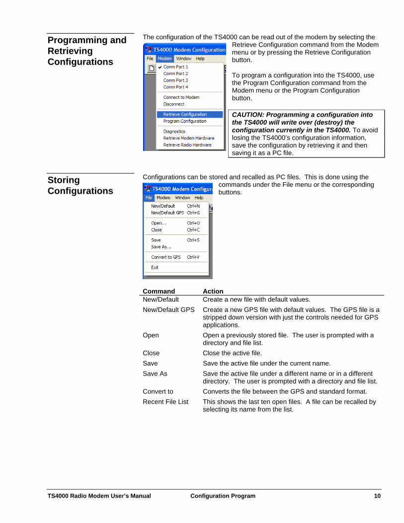
The configuration of the TS4000 can be read out of the modem by selecting the Retrieve Configuration command from the Modem menu or by pressing the Retrieve Configuration button.
Programming and Retrieving Configurations
To program a configuration into the TS4000, use the Program Configuration command from the Modem menu or the Program Configuration button. CAUTION: Programming a configuration into the TS4000 will write over (destroy) the configuration currently in the TS4000. To avoid losing the TS4000’s configuration information, save the configuration by retrieving it and then saving it as a PC file.
red and recalled as PC files. This is done using the commanStoring
Configurations Configurations can be sto
ds under the File menu or the corresponding
buttons.
Command Action New/Default Create a new file with default values. New/Default GPS
version with just the controls needed for GPS
Open red file. The user is prompted with a
Save As st.
Recent File List s. A file can be recalled by selecting its name from the list.
Create a new GPS file with default values. The GPS file is a stripped downapplications. Open a previously stodirectory and file list.
Close Close the active file. Save Save the active file under the current name.
Save the active file under a different name or in a different directory. The user is prompted with a directory and file li
Convert to Converts the file between the GPS and standard format. This shows the last ten open file
TS4000 Radio Modem User’s Manual Configuration Program 11
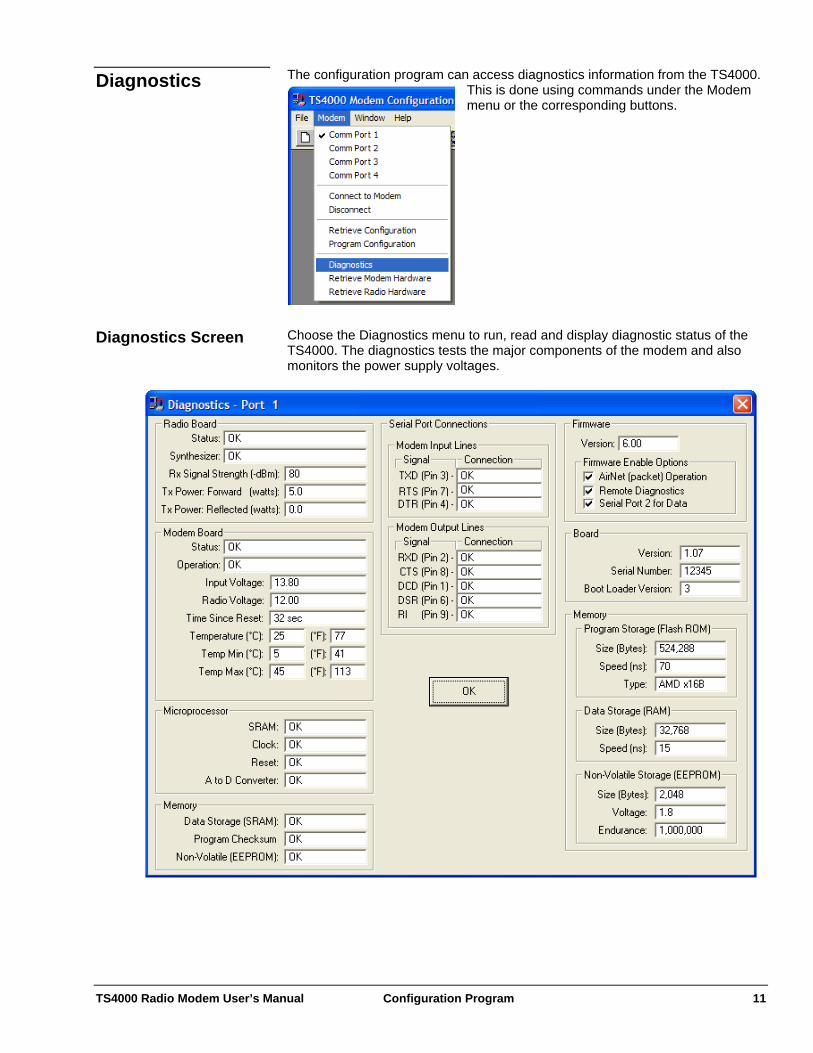
The configuration program can access diagnostics information from the TS4000. This is done using commands under the Modem menu or the corresponding buttons.
Diagnostics
Choose the Diagnostics menu to run, read and display diagnostic status of the TS4000. The diagnostics tests the major components of the modem and also monitors the power supply voltages.
Diagnostics Screen

TS4000 Radio Modem User’s Manual Configuration Program 12
Choose the Retrieve Modem Hardware menu to read and display the modem hardware details. These include details on the firmware version and memory configuration. These modem hardware values are set at the factory based on the modem hardware included in the TS4000 and cannot be changed.
Modem Hardware Screen
Choose the Retrieve Radio Hardware menu to read and display the radio hardware details. This includes details about the radio’s frequency, channel spacing and transmit power. These values are set at the factory based on the radio hardware included in the TS4000 and cannot be changed.
Radio Hardware Screen
TS4000 Radio Modem User’s Manual Serial Port 13
Serial Port The serial port provides an asynchronous data connection between the TS4000 and the host equipment. The TS4000 serial port is a standard RS-232 serial port with a number of options to allow connection to a wide variety of serial host equipment. The EIA (Electronic Industries Association) RS-232C standard is a standard for short distance (less than 50 feet) serial communications. The standard defines the electrical signal levels, interface characteristics and the operation of the control signals (handshake lines). Although the standard defines the operation of the handshake lines, there is significant variation in the way these signals are used by different equipment.
RS-232 Serial Port Basics
The RS-232 standard does not require the use of a specific connector. However, most asynchronous RS-232 serial ports use either a 9 pin or 25 pin subminiature D connector. The same signals are provided with both connectors, but of course the pinouts are different (see Appendix A - Serial Port).
Connectors
RS-232 serial ports come in two varieties - DCE (Data Communication Equipment) and DTE (Data Terminal Equipment). This defines the direction of the serial port’s lines (driven or received). It also typically defines the polarity of the connector. DCEs typically use female pin connectors and DTEs typically use male pin connectors.
DCE vs. DTE
Connecting a DCE port to a DTE is the most common setup and requires a standard straight through cable (i.e. pin 1 to pin 1, pin 2 to pin 2, etc.). When connecting two DCEs or two DTEs together a null modem cable is required. The purpose of a null modem cable is to cross connect the appropriate signals. However, null modem cables are not all the same and therefore it is important to verify that a specific cable is appropriate for a specific application. The TS4000 is designed to work with asynchronous serial ports. Asynchronous ports do not use clocks or timing signals to synchronize data transfers. Instead data is framed into asynchronous characters which the ports synchronize to.
Asynchronous Data
An asynchronous character consists of a start bit, data bits and stop bits. The start bit indicates the beginning of a character. The number of data bits varies, but is typically between 7 and 9 bits. The data bits sometimes include a parity bit that provides error check information with each character. The number of stop bits also varies but is typically 1 or 2 bits. Flow control is the method for controlling the flow of data between the DCE and DTE. Flow control is used to prevent the DTE and DCE data receive buffers from overflowing. There are several different methods used for flow control and as with everything related to RS-232 there is no one standard. The two main variations of flow control are hardware flow control that utilizes the RS-232 handshake lines and software flow control that utilizes characters sent along with the normal data.
Flow Control
Hardware flow control typically uses two control lines, one for each direction of data. When a port activates its flow control signal it is indicating its readiness to receive data. Deactivating the flow control signal indicates that the port can no longer receive data because its buffer is full or close to full.
Hardware Flow Control
TS4000 Radio Modem User’s Manual Serial Port 14
The most common form of hardware flow control, and the one used by most full duplex wired (as opposed to wireless) modems, is RTS/CTS. With RTS/CTS flow control, RTS provides flow control for the DTE and CTS provides flow control for the DCE. One problem with RTS/CTS flow control is that for many half duplex modems (most wireless modems) the RTS signal is used to frame transmit data going from the DTE to the DCE. This use of RTS conflicts with using RTS for flow control of data to the DTE. An alternative form of hardware flow control is DTR/DSR. With DTR/DSR flow control, DTR provides the flow control for the DTE and DSR provides the flow control for the DCE. Software flow control uses characters sent over the data lines to control data flow. These characters are sent along with the normal flow of data between the DTE and DCE. There is typically one character that is used to stop the flow of data and a different character to restart data flow. Software flow control can use any characters to start and stop flow. However the most common characters used are the ASCII XON (starts flow) and XOFF (stops flow) characters. Because these are the most common characters used, software flow control is often referred to as XON/XOFF flow control. The ASCII XON character is the decimal character 17 (0x11 hex) and is also known as DC1 or Ctrl-Q. The ASCII XOFF character is the decimal character 19 (0x13 hex) and is also known as DC3 or Ctrl-S (See Appendix B - ASCII Character Set).
Software Flow Control
A problem with software flow control is that the normal data passed over the communications link cannot include the flow control characters. If it does, the flow of data will be incorrectly stopped or started. This limits the characters that can be used by the host application and also prevents the sending of binary (all character numbers) data. The TS4000 serial ports are setup as DCEs (Data Communication Equipment). The TS4000 with the standard case uses two 9 pin subminiature D connectors with female pins for the serial ports. The TS4000 with the watertight case uses a 19 pin environmentally sealed LEMO connector (see Appendix A - Serial Port).
Serial Port Connector
Signal Levels Serial port 1 can be configured for either RS-232 or TTL signal levels. To change the signal levels, the modem must be opened and the four jumper plugs next to the serial port connector set to the desired position (see Appendix A - Serial Port, Appendix F - Internal Jumper Block).
Serial Port 1
Serial port 2 is always set for RS-232 signal levels. Serial Port 2 The serial ports can be used with RS-485 signal levels through the use of an external signal converter. These external signal converters can be obtained from Teledesign.
RS-485
The serial ports can be setup to provide different internal electrical connections to the DTR, DSR and RI pins. To change the pin connections, the modem must be opened and the jumper plugs next to the serial port connector set to the desired position (see Appendix F - Internal Jumper Block).
Signal Options
TS4000 Radio Modem User’s Manual Serial Port 15
The RI (Ring Indicator) pin is pin 9 of a standard 9 pin subminiature D connector and is an output for DCEs (the TS4000). The TS4000 has no internal RI signal and therefore the RI pin is normally left unconnected.
RI Pin Signal Options
As an alternative, the RI pin can be connected as a power pin into the TS4000. This is non-standard use of this pin and therefore care should be taken when connecting the TS4000 to other serial devices. For most serial devices this is not a problem because RI is a modem (DCE) output and the TS4000 power supply mostly falls within the allowed voltage range for RS-232 signals. Therefore the power voltage on this pin is interpreted as an active RI signal. For systems that use the RI signal differently, or cannot operate with power on this pin, this pin should be disconnected between the TS4000 and the host equipment.
RI for Modem Power
As an alternative, the RI pin can be connected to the internal DSR output signal. RI Connected for DSR The DSR (Data Set Ready) pin is pin 6 of a standard 9 pin subminiature D connector and is an output for DCEs (the TS4000). For the TS4000, the DSR pin is normally connected to the internal DSR output signal.
DSR Pin Signal Options
As an alternative, the DSR pin can be set to always be in the active high state. In this case it is internally connected to +5 volts through a 1 K ohm resistor.
DSR Always High
The DTR (Data Terminal Ready) pin is pin 4 of a standard 9 pin subminiature D connector and is an input for DCEs (the TS4000). For the TS4000, the DTR pin is normally connected to the internal DTR input signal.
DTR Pin Signal Options
As an alternative, the DTR pin of serial port 1 can be connected as a power pin into the TS4000. This option is only available for serial port 1.
DTR for Modem Power
Caution: The use of the DTR pin for power is non-standard. Therefore the TS4000 serial port must not be connected to a standard serial device that drives the DTR pin (i.e. a PC). Connecting a TS4000, that is configured for power through the DTR pin, to a device that drives the DTR pin can result in the power supply voltage of the TS4000 being shorted to the DTR output of the host serial port. This could damage to the host device. Therefore, when connecting the TS4000 to a PC for configuration, make sure that the cable does not have a DTR (pin 4) connection.
TS4000 Radio Modem User’s Manual Serial Port 16
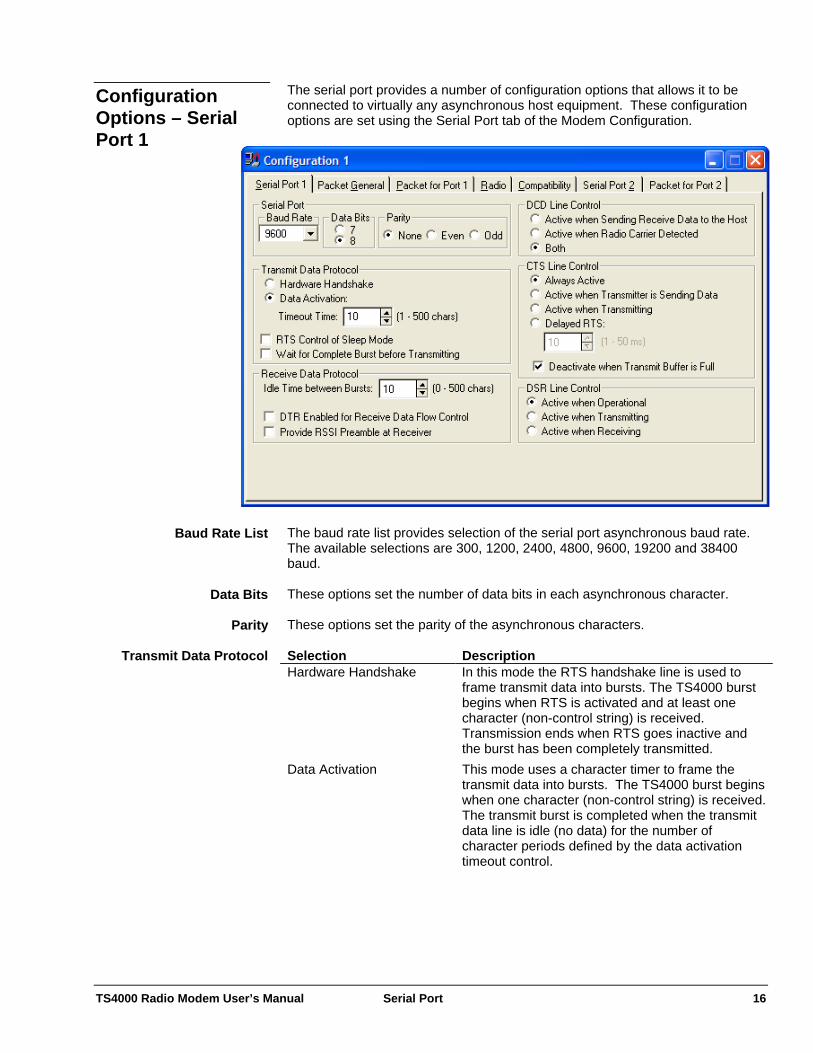
The serial port provides a number of configuration options that allows it to be connected to virtually any asynchronous host equipment. These configuration options are set using the Serial Port tab of the Modem Configuration.
Configuration Options – Serial Port 1
The baud rate list provides selection of the serial port asynchronous baud rate. The available selections are 300, 1200, 2400, 4800, 9600, 19200 and 38400 baud.
Baud Rate List
These options set the number of data bits in each asynchronous character. Data Bits These options set the parity of the asynchronous characters. Parity Selection Description Hardware Handshake In this mode the RTS handshake line is used to
frame transmit data into bursts. The TS4000 burst begins when RTS is activated and at least one character (non-control string) is received. Transmission ends when RTS goes inactive and the burst has been completely transmitted.
Data Activation This mode uses a character timer to frame the transmit data into bursts. The TS4000 burst begins when one character (non-control string) is received. The transmit burst is completed when the transmit data line is idle (no data) for the number of character periods defined by the data activation timeout control.
Transmit Data Protocol
TS4000 Radio Modem User’s Manual Serial Port 17
Selection Description Data Activation Timeout (Timeout Time)
This control sets the number of character periods of idle required on the serial port's transmit data line to declare the end of a transmit burst.
Char Period = Char Length / Baud Rate Where: Char Length = Data Bits + Parity + 2
Data Bits is the value selected from the Data Bits control. Parity is 0 if none is selected from the Parity control and 1 if even or odd is selected. The 2 added to the accounts for the start and stop bits of an asynchronous character. Baud Rate is the value selected from the baud rate list.
When this is active RTS is used to control sleep mode. When RTS is inactive, the modem will enter sleep mode until RTS is activated.
RTS Control of Sleep Mode
This option only has effect only in transparent (non-packet) mode. In packet mode the TS4000 always waits for a complete burst before beginning transmission.
Wait For Complete Burst Before Beginning
Transmission Selection Description Disabled The modem begins transmitting as soon as it
receives the first non-control character of a transmit burst.
Enabled The modem waits for a complete transmit burst before it begins transmitting.
TS4000 Radio Modem User’s Manual Serial Port 18
Selection Description Idle Time Between Bursts This sets the minimum amount of time (in character
periods) that the receive data (RXD) line will be idle (inactive) between received bursts of data. If this value is set to zero, the receive data line may remain active continuously when multiple bursts of receive data are transferred to the host. If the DCD line option is set for the Active when Sending Receive Data to the User then the DCD line will also be inactive during the receive data line idle times.
DTR Enabled for Receive Data Flow Control
When enabled, DTR acts as flow control for receive data coming from the TS4000 to the host. When DTR is inactive, data received by the TS4000 is stored in an internal buffer and inhibited from being sent to the host equipment. The flow of receive data out of the serial port resumes when DTR is activated.
Provide RSSI at Receiver When this control is activated, the RSSI (Receive Signal Strength Indication) of the received packet is sent as a prefix string to the data. The string is made up of ASCII characters as follows: +TSRxxx
where xxx = receive signal level in –dBms (i.e. +TSR087 = a –87dBm signal level)
Note that because the value is in –dBms (negative dBms) a larger receive signal is represented with a smaller 3 digit number.
Receive Data Protocol
Selection Description Active when Sending Receive Data to the User
DCD is active when receive data is sent out of the TS4000 via the serial port.
Active when Receiving DCD is active when the TS4000 detects a signal on the radio channel. This mode can be used to remote the receive light.
Both DCD is active when either receive data is being sent out the serial port or when a signal is detected on the radio channel. Note that for most conditions and configurations these states overlap.
DCD Line Control

TS4000 Radio Modem User’s Manual Serial Port 19
Selection Description Always Active The CTS line is active. Active when Transmitter is Sending Data
CTS is normally inactive and is activated when the TS4000 is transmitting and the radio channel is ready for the transmission of data.
Active when Transmitting CTS is normally inactive and is activated when the TS4000 is transmitting. Note that the modem begins transmitting only after it has received at least one character (non-control string) of data. This selection can be used to remote the transmit light.
Delayed RTS CTS is normally inactive and is activated a fixed time after RTS becomes active. The time is controlled with the RTS to CTS delay value.
Deactivate when Transmit Buffer is Full
When this is enabled, CTS is deactivated when the transmit buffer is full. This setting effects all of the above options.
CTS Line Control
Selection Description Active when Operational DSR is active when the TS4000 is powered and
has passed self test. Active when Transmitting DSR is active when the TS4000 is transmitting.
This selection can be used to remote the transmit light.
Active when Receiving DSR is active when the TS4000 detects a signal on the radio channel. This mode can be used to remote the receive light.
DSR Line Control
TS4000 Radio Modem User’s Manual Serial Port 20
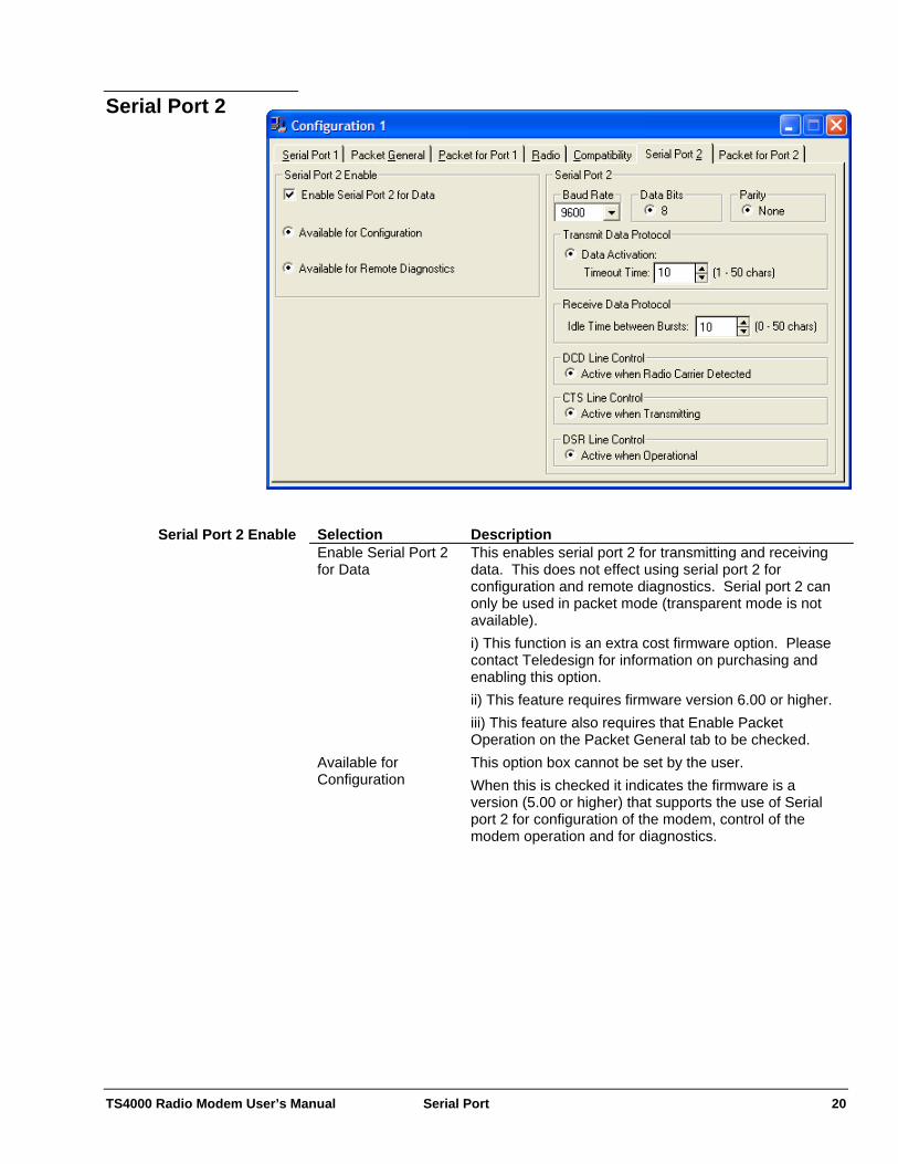
Serial Port 2
Selection Description Enable Serial Port 2 for Data
This enables serial port 2 for transmitting and receiving data. This does not effect using serial port 2 for configuration and remote diagnostics. Serial port 2 can only be used in packet mode (transparent mode is not available). i) This function is an extra cost firmware option. Please contact Teledesign for information on purchasing and enabling this option. ii) This feature requires firmware version 6.00 or higher. iii) This feature also requires that Enable Packet Operation on the Packet General tab to be checked.
Available for Configuration
This option box cannot be set by the user. When this is checked it indicates the firmware is a version (5.00 or higher) that supports the use of Serial port 2 for configuration of the modem, control of the modem operation and for diagnostics.
Serial Port 2 Enable
TS4000 Radio Modem User’s Manual Serial Port 21
Selection Description Available for Remote Diagnostics
This option box cannot be set by the user. When this is checked it indicates that the remote diagnostics firmware option is enabled (see Remote Diagnostics). i) This function is an extra cost firmware option. Please contact Teledesign for information on purchasing and enabling this option. ii) This function also requires version 5.00 or higher firmware. iii) Remote diagnostics also requires that AirNet packet operation is enabled (see AirNet Packet Protocol).
The baud rate list provides selection of the serial port asynchronous baud rate. The serial port 2 baud rate is fixed at 9600 baud.
Baud Rate List
The number of data bits for serial port 2 is fixed at eight. Data Bits The parity of serial port 2 is fixed at no parity. Parity Selection Description Data Activation This mode uses a character timer to frame the
transmit data into bursts. The TS4000 burst begins when one character (non-control string) is received. The transmit burst is completed when the transmit data line is idle (no data) for the number of character periods defined by the data activation timeout control.
Timeout Time This control sets the number of character periods of idle required on the serial port's transmit data line to declare the end of a transmit burst.
Char Period = Char Length / Baud Rate Where: Char Length = Data Bits + Parity + 2
Data Bits is the value selected from the Data Bits control. Parity is 0 if none is selected from the Parity control and 1 if even or odd is selected. The 2 added to the accounts for the start and stop bits of an asynchronous character. Baud Rate is the value selected from the baud rate list.
Transmit Data Protocol
This sets the minimum amount of time (in character periods) that the receive data (RXD) line will be idle (inactive) between received bursts of data. If this value is set to zero, the receive data line may remain active continuously when multiple bursts of receive data are transferred to the host.
Receive Data Protocol – Idle Time Between Bursts
If the DCD line option is set for the Active when Sending Receive Data to the User then the DCD line will also be inactive during the receive data line idle times. DCD is active when the TS4000 detects a signal on the radio channel. This mode can be used to remote the receive light.
DCD Line Control – Active when Radio Carrier
Detected
TS4000 Radio Modem User’s Manual Serial Port 22
CTS is active when the TS4000 is transmitting. This selection can be used to remote the transmit light.
CTS Line Control – Active when Transmitting
DSR is active when the TS4000 is powered and there are no active faults. An active fault is indicated by a flashing power light.
DSR Line Control – Active when Operational
TS4000 Radio Modem User’s Manual Radio Setup 23
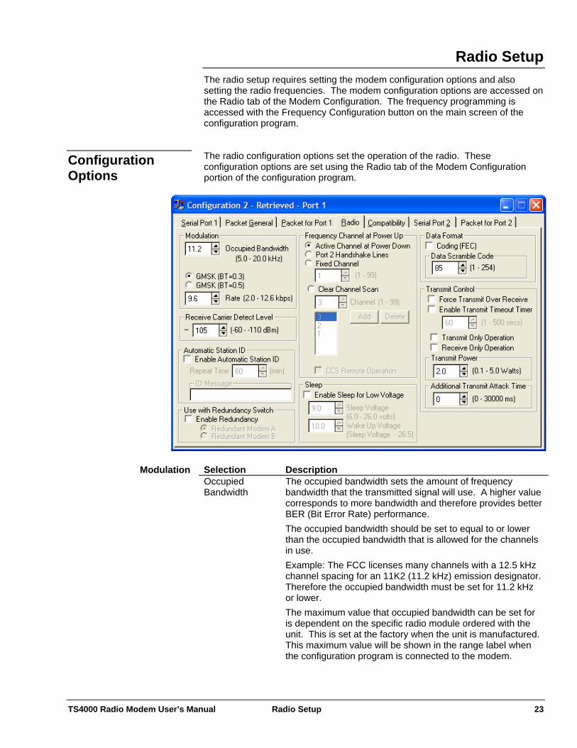
Radio Setup The radio setup requires setting the modem configuration options and also setting the radio frequencies. The modem configuration options are accessed on the Radio tab of the Modem Configuration. The frequency programming is accessed with the Frequency Configuration button on the main screen of the configuration program. The radio configuration options set the operation of the radio. These configuration options are set using the Radio tab of the Modem Configuration portion of the configuration program.
Configuration Options
Selection Description Occupied Bandwidth
The occupied bandwidth sets the amount of frequency bandwidth that the transmitted signal will use. A higher value corresponds to more bandwidth and therefore provides better BER (Bit Error Rate) performance. The occupied bandwidth should be set to equal to or lower than the occupied bandwidth that is allowed for the channels in use. Example: The FCC licenses many channels with a 12.5 kHz channel spacing for an 11K2 (11.2 kHz) emission designator. Therefore the occupied bandwidth must be set for 11.2 kHz or lower. The maximum value that occupied bandwidth can be set for is dependent on the specific radio module ordered with the unit. This is set at the factory when the unit is manufactured. This maximum value will be shown in the range label when the configuration program is connected to the modem.
Modulation
TS4000 Radio Modem User’s Manual Radio Setup 24
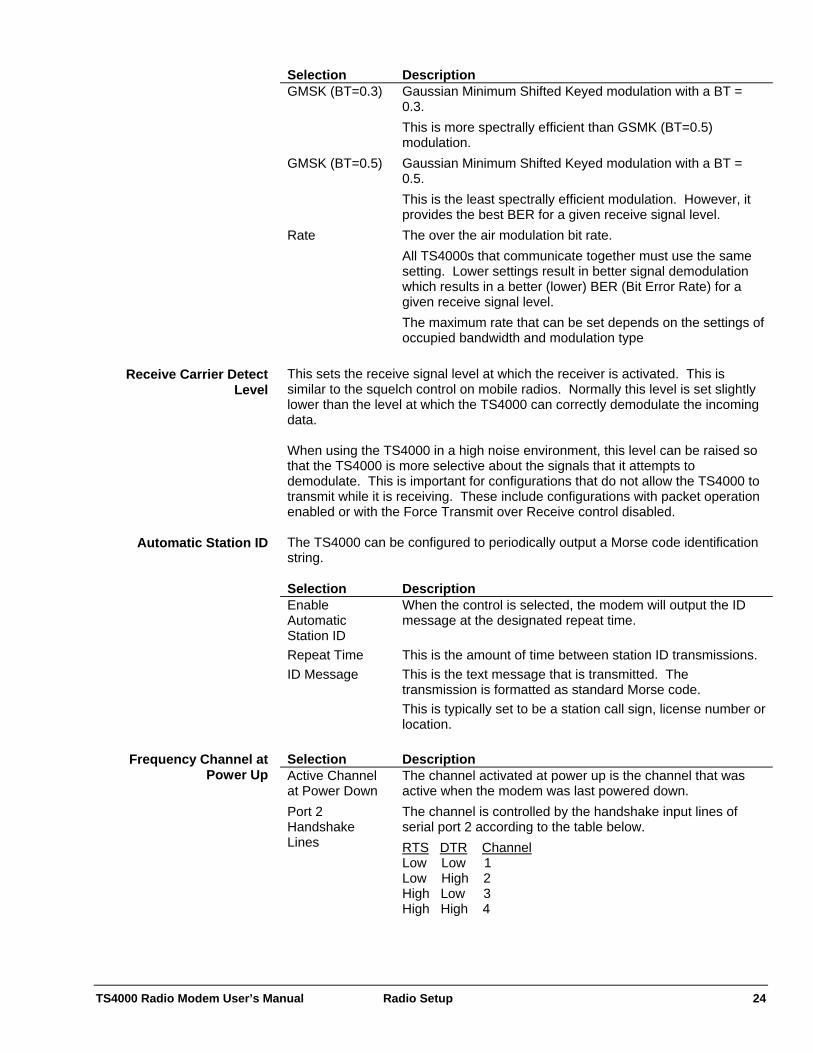
Selection Description GMSK (BT=0.3) Gaussian Minimum Shifted Keyed modulation with a BT =
0.3. This is more spectrally efficient than GSMK (BT=0.5) modulation.
GMSK (BT=0.5) Gaussian Minimum Shifted Keyed modulation with a BT = 0.5. This is the least spectrally efficient modulation. However, it provides the best BER for a given receive signal level.
Rate The over the air modulation bit rate. All TS4000s that communicate together must use the same setting. Lower settings result in better signal demodulation which results in a better (lower) BER (Bit Error Rate) for a given receive signal level. The maximum rate that can be set depends on the settings of occupied bandwidth and modulation type
This sets the receive signal level at which the receiver is activated. This is similar to the squelch control on mobile radios. Normally this level is set slightly lower than the level at which the TS4000 can correctly demodulate the incoming data.
Receive Carrier Detect Level
When using the TS4000 in a high noise environment, this level can be raised so that the TS4000 is more selective about the signals that it attempts to demodulate. This is important for configurations that do not allow the TS4000 to transmit while it is receiving. These include configurations with packet operation enabled or with the Force Transmit over Receive control disabled. The TS4000 can be configured to periodically output a Morse code identification string.
Automatic Station ID
Selection Description Enable Automatic Station ID
When the control is selected, the modem will output the ID message at the designated repeat time.
Repeat Time This is the amount of time between station ID transmissions. ID Message This is the text message that is transmitted. The
transmission is formatted as standard Morse code. This is typically set to be a station call sign, license number or location.
Selection Description Active Channel at Power Down
The channel activated at power up is the channel that was active when the modem was last powered down.
Port 2 Handshake Lines
The channel is controlled by the handshake input lines of serial port 2 according to the table below. RTS DTR Channel Low Low 1 Low High 2 High Low 3 High High 4
Frequency Channel at Power Up
TS4000 Radio Modem User’s Manual Radio Setup 25
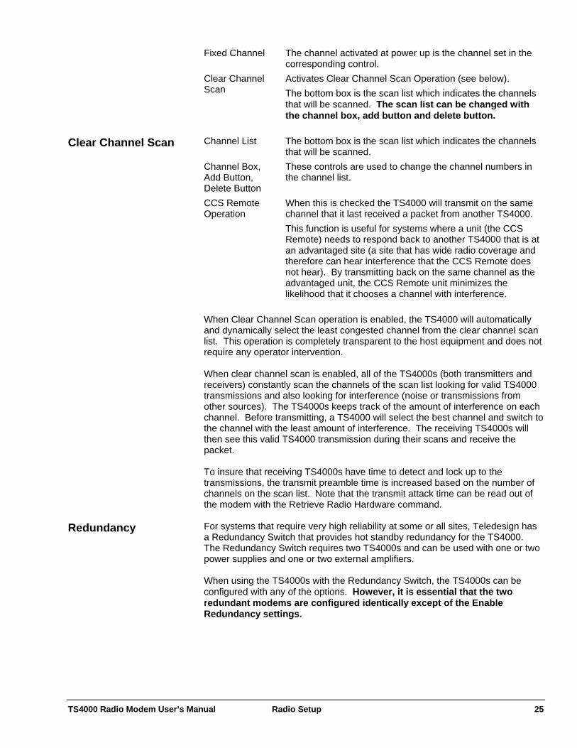
Fixed Channel The channel activated at power up is the channel set in the corresponding control.
Clear Channel Scan
Activates Clear Channel Scan Operation (see below). The bottom box is the scan list which indicates the channels that will be scanned. The scan list can be changed with the channel box, add button and delete button.
Channel List The bottom box is the scan list which indicates the channels
that will be scanned. Channel Box, Add Button, Delete Button
These controls are used to change the channel numbers in the channel list.
CCS Remote Operation
When this is checked the TS4000 will transmit on the same channel that it last received a packet from another TS4000. This function is useful for systems where a unit (the CCS Remote) needs to respond back to another TS4000 that is at an advantaged site (a site that has wide radio coverage and therefore can hear interference that the CCS Remote does not hear). By transmitting back on the same channel as the advantaged unit, the CCS Remote unit minimizes the likelihood that it chooses a channel with interference.
Clear Channel Scan
When Clear Channel Scan operation is enabled, the TS4000 will automatically and dynamically select the least congested channel from the clear channel scan list. This operation is completely transparent to the host equipment and does not require any operator intervention. When clear channel scan is enabled, all of the TS4000s (both transmitters and receivers) constantly scan the channels of the scan list looking for valid TS4000 transmissions and also looking for interference (noise or transmissions from other sources). The TS4000s keeps track of the amount of interference on each channel. Before transmitting, a TS4000 will select the best channel and switch to the channel with the least amount of interference. The receiving TS4000s will then see this valid TS4000 transmission during their scans and receive the packet. To insure that receiving TS4000s have time to detect and lock up to the transmissions, the transmit preamble time is increased based on the number of channels on the scan list. Note that the transmit attack time can be read out of the modem with the Retrieve Radio Hardware command. For systems that require very high reliability at some or all sites, Teledesign has a Redundancy Switch that provides hot standby redundancy for the TS4000. The Redundancy Switch requires two TS4000s and can be used with one or two power supplies and one or two external amplifiers.
Redundancy
When using the TS4000s with the Redundancy Switch, the TS4000s can be configured with any of the options. However, it is essential that the two redundant modems are configured identically except of the Enable Redundancy settings.
TS4000 Radio Modem User’s Manual Radio Setup 26
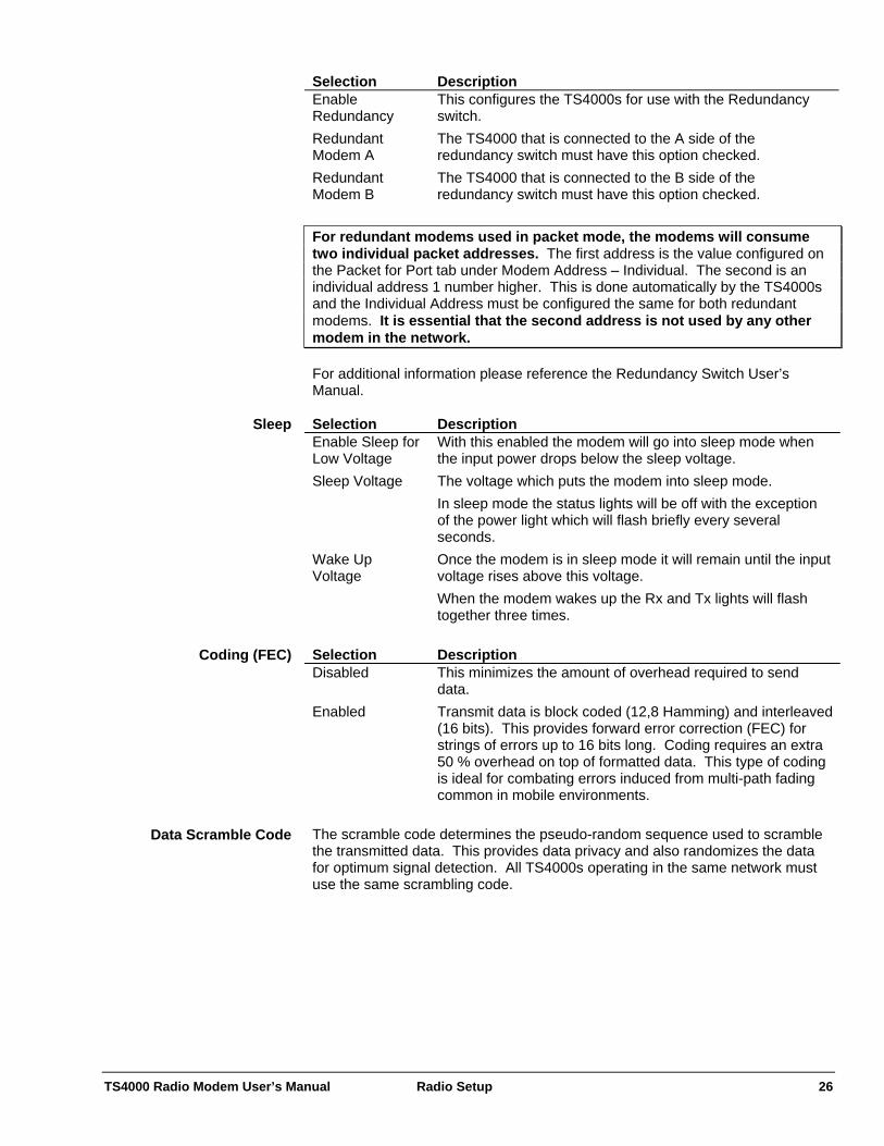
Selection Description Enable Redundancy
This configures the TS4000s for use with the Redundancy switch.
Redundant Modem A
The TS4000 that is connected to the A side of the redundancy switch must have this option checked.
Redundant Modem B
The TS4000 that is connected to the B side of the redundancy switch must have this option checked.
For redundant modems used in packet mode, the modems will consume two individual packet addresses. The first address is the value configured on the Packet for Port tab under Modem Address – Individual. The second is an individual address 1 number higher. This is done automatically by the TS4000s and the Individual Address must be configured the same for both redundant modems. It is essential that the second address is not used by any other modem in the network. For additional information please reference the Redundancy Switch User’s Manual. Selection Description Enable Sleep for Low Voltage
With this enabled the modem will go into sleep mode when the input power drops below the sleep voltage.
Sleep Voltage The voltage which puts the modem into sleep mode. In sleep mode the status lights will be off with the exception of the power light which will flash briefly every several seconds.
Wake Up Voltage
Once the modem is in sleep mode it will remain until the input voltage rises above this voltage. When the modem wakes up the Rx and Tx lights will flash together three times.
Sleep
Selection Description Disabled This minimizes the amount of overhead required to send
data. Enabled Transmit data is block coded (12,8 Hamming) and interleaved
(16 bits). This provides forward error correction (FEC) for strings of errors up to 16 bits long. Coding requires an extra 50 % overhead on top of formatted data. This type of coding is ideal for combating errors induced from multi-path fading common in mobile environments.
Coding (FEC)
The scramble code determines the pseudo-random sequence used to scramble the transmitted data. This provides data privacy and also randomizes the data for optimum signal detection. All TS4000s operating in the same network must use the same scrambling code.
Data Scramble Code
TS4000 Radio Modem User’s Manual Radio Setup 27
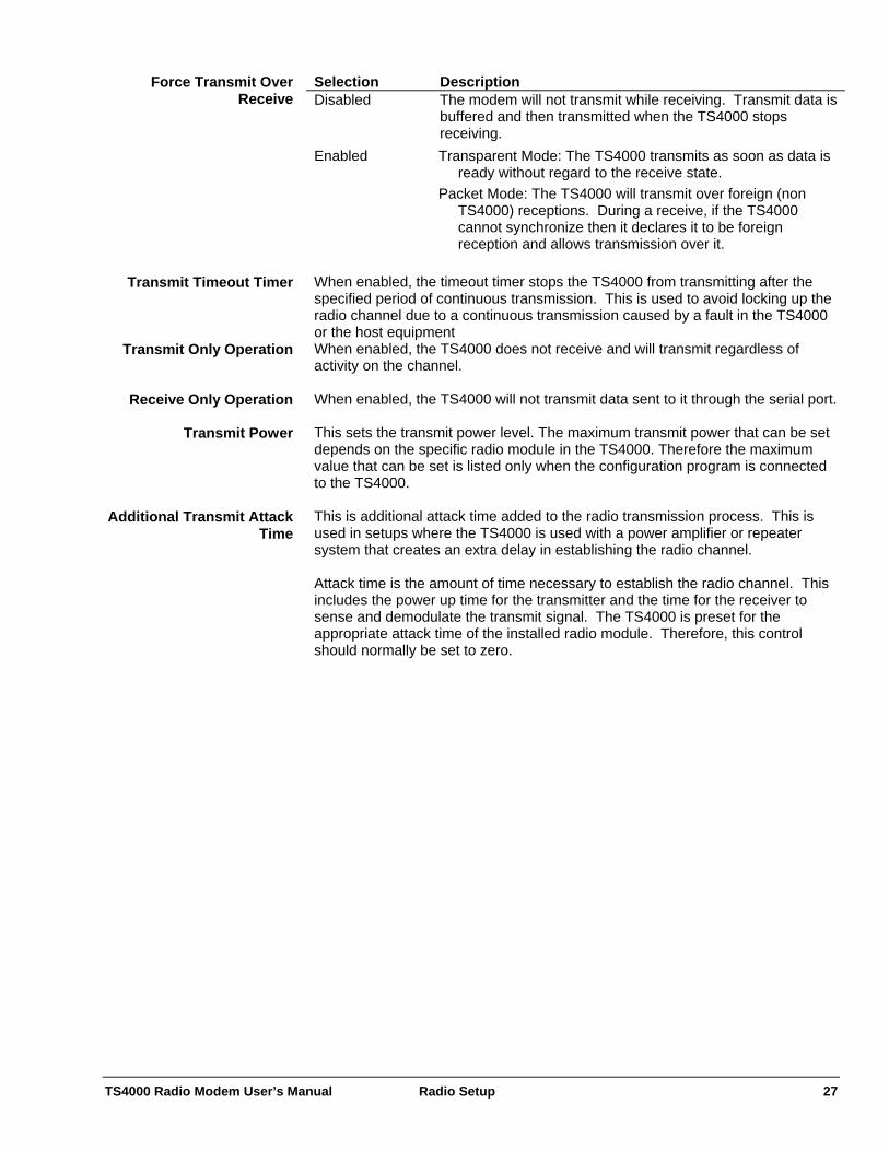
Selection Description Disabled The modem will not transmit while receiving. Transmit data is
buffered and then transmitted when the TS4000 stops receiving.
Enabled Transparent Mode: The TS4000 transmits as soon as data is ready without regard to the receive state.
Packet Mode: The TS4000 will transmit over foreign (non TS4000) receptions. During a receive, if the TS4000 cannot synchronize then it declares it to be foreign reception and allows transmission over it.
Force Transmit Over Receive
When enabled, the timeout timer stops the TS4000 from transmitting after the specified period of continuous transmission. This is used to avoid locking up the radio channel due to a continuous transmission caused by a fault in the TS4000 or the host equipment
Transmit Timeout Timer
When enabled, the TS4000 does not receive and will transmit regardless of activity on the channel.
Transmit Only Operation
When enabled, the TS4000 will not transmit data sent to it through the serial port. Receive Only Operation This sets the transmit power level. The maximum transmit power that can be set depends on the specific radio module in the TS4000. Therefore the maximum value that can be set is listed only when the configuration program is connected to the TS4000.
Transmit Power
This is additional attack time added to the radio transmission process. This is used in setups where the TS4000 is used with a power amplifier or repeater system that creates an extra delay in establishing the radio channel.
Additional Transmit Attack Time
Attack time is the amount of time necessary to establish the radio channel. This includes the power up time for the transmitter and the time for the receiver to sense and demodulate the transmit signal. The TS4000 is preset for the appropriate attack time of the installed radio module. Therefore, this control should normally be set to zero.

TS4000 Radio Modem User’s Manual Radio Setup 28
The TS4000 comes in various frequency bands (i.e. 450 to 470 MHz) and can be programmed for any valid channel within a given frequency band. The TS4000 can be set for up to 99 channels. A channel consists of a receive frequency and a transmit frequency which can be set to the same or different frequencies.
Frequency Programming
406.0 to 406.1 MHz Operation
The frequency band from 406.0 to 406.1 MHz is reserved for use by distress beacons. Therefore, the TS4000 should not be programmed to transmit on any frequency within this band. Caution should be used when programming frequencies into the TS4000 to eliminate the possibility of TS4000 users interfering with rescue operations on this band. Frequency channels are programmed into the TS4000 using the configuration program. To access the frequency program screen press the Frequency Configuration button on the main screen of the configuration program. Frequency channel configuration settings are programmed into and retrieved from the TS4000 the same as the modem configuration settings. There are three ways to program frequencies into the TS4000 - cloning, using a preprogrammed file and being an authorized service organization.
Methods of Programming Channels
The FCC rules state that only authorized organizations should be allowed to arbitrarily change the frequencies programmed into radio devices. Because of this, a software enable code is required to enable the arbitrary frequency programming capability of the TS4000 configuration program. Note that this enable code is not required to retrieve and display the channel frequencies programmed in the TS4000.
1) Frequency Programming for
Authorized Organizations
Contact Teledesign Systems to find the nearest authorized service center. Cloning is copying the channels from one unit into another unit. Cloning can be done by any user and does not require a software enable code. Cloning is accomplished by first retrieving the desired frequency configuration from a unit. This retrieved file can then be used to program another unit. Note that if the retrieved frequency file is changed it can no longer be used to program another unit.
2) Frequency Cloning
Frequency programming can also be accomplished using a preprogrammed frequency file. Preprogrammed frequency files must be obtained from Teledesign. To use the preprogrammed file, first open the file with the frequency configuration program, then program the TS4000 with the opened file.
3) Preprogrammed Frequency File
TS4000 Radio Modem User’s Manual Radio Setup 29
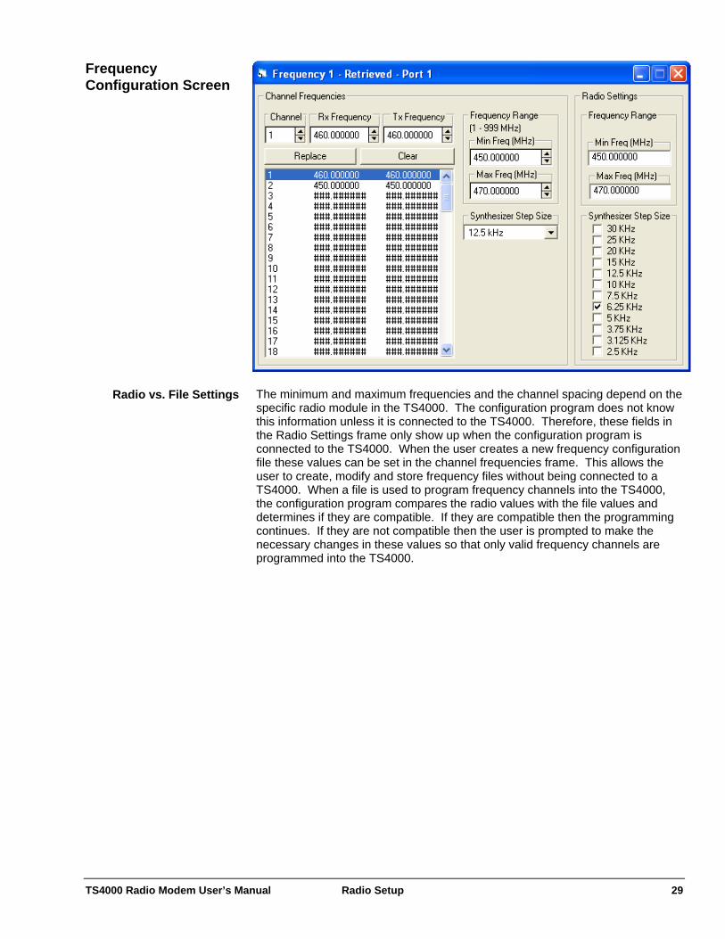
Frequency Configuration Screen
The minimum and maximum frequencies and the channel spacing depend on the specific radio module in the TS4000. The configuration program does not know this information unless it is connected to the TS4000. Therefore, these fields in the Radio Settings frame only show up when the configuration program is connected to the TS4000. When the user creates a new frequency configuration file these values can be set in the channel frequencies frame. This allows the user to create, modify and store frequency files without being connected to a TS4000. When a file is used to program frequency channels into the TS4000, the configuration program compares the radio values with the file values and determines if they are compatible. If they are compatible then the programming continues. If they are not compatible then the user is prompted to make the necessary changes in these values so that only valid frequency channels are programmed into the TS4000.
Radio vs. File Settings
TS4000 Radio Modem User’s Manual Radio Setup 30
During normal operation, the frequency channel can be switched on the fly with: Channel Switching 1) A control String through either serial port.
2) The DTR and RTS control lines on serial port 2. For details, see Radio Setup – Frequency Channel at Power Up.
3) Automatically with the Clear Channel Scan function. For details, see Radio Setup – Frequency Channel at Power Up.
The channel is switched by sending the following ASCII character string to either of the TS4000’s serial port.
Channel Change with a Control String
+TSCxx Where: xx = Channel number from 01 to 99
Note: The letter characters must be upper case. The channel change control string is sent to the modem the same as standard transmit data. For the control string to be recognized it must be the first characters of a burst of transmit data. If the control string is sent alone (no data following), then the TS4000 will switch to the receive frequency of the new channel pair and wait in receive mode. If the control string is sent with a transmit data burst following it, then the TS4000 will switch to the transmit frequency of the new channel pair and transmit the burst. The active channel can be determined with the channel query string. This is done with the following ASCII character string.
Determining the Active Channel
+TSC? Note: The letter characters must be upper case. The response string is sent out the serial port and is as follows. 1) +TSCxx For single channel systems
Where: xx = Channel number from 01 to 99 2) +TSCCS For modems configured for clear channel scan If a frequency channel is selected that has not been programmed with valid frequencies, the modem will not receive or transmit and the RX and TX lights will alternately flash.
Invalid Channel Selection
The channel that the TS4000 activates at power up depends on the setting of the Frequency Channel at Power Up control (see Radio Setup – Frequency Channel at Power Up).
Channel at Power Up

TS4000 Radio Modem User’s Manual Radio Setup 31
Compatibility mode allows the TS4000 to be setup to be compatible with our previous generation TSI9600 radio modem. Compatibility
Selection Description Trimble Compatible Mode
This mode allows the TS4000 to communicate with Trimble TrimMark and TrimTalk GPS data links.
TSI9600 Compatibility Mode
This mode allows the TS4000 to communicate with Teledesign TSI9600s.
3295 Compatibility
This configures the TSI9600 compatibility mode to be suitable for operation with JDT-3295 modems. The JDT-3295 is a TSI9600 with slightly different firmware. Typically the 3295 consisted of an enclosed TSI9600 modem and interface board connected with a cable to a separately enclosed radio transceiver.
Enable
Selection Description Data Scrambling This control is equivalent to the data scrambling DIP switch
on the TSI9600 modem board. On the TSI9600 this switch is marked “H-F”.
Transmit Deviation
This sets the amount of transmit deviation. This should be set to match the level of the TSI9600. Normally this should not be changed from the default value.
Data Protocol

TS4000 Radio Modem User’s Manual Radio Setup 32
Selection Description Transmit Data Inversion
This controls the transmit data polarity in 3295 mode. This control corresponds to the transmit polarity jumper on the interface board.
Receive Data Inversion
This controls the receive data polarity in 3295 mode. This control corresponds to the receive polarity jumper on the interface board.
Data Polarity
This should be set to match the type of Trimble data link that the TS4000 must operate with.
Trimble Options - Mode
This should be set to match the channel spacing of the Trimble data link that the TS4000 must operate with.
Trimble Options – Channel Spacing
These controls enable store and forward repeater operation in Trimble compatible mode.
Trimble Options – Store and Forward Repeaters
TS4000 Radio Modem User’s Manual AirNet Packet Protocol 33
AirNet Packet Protocol AirNet is an embedded packet protocol available in some Teledesign Systems modems. AirNet provides a complete protocol that manages the end to end data transfers of wireless networks. The AirNet protocol is flexible and configurable so that it can be used with any host (user) system or network architecture.
Overview
The basic purpose of the AirNet packet protocol is to ensure that data is reliably transferred between nodes in the network. This means preventing data from being lost, repeated or corrupted at the receiving nodes. This is accomplished by combining transmit data into packets which contain user data and control information. The control information includes addressing, sequencing and error detection. Addressing information allows receiving nodes to determine if a packet is intended for them and also who the source of the packet was. Sequence information is used so that the data can be reconstructed in the correct order, and so that repeated packets of the same data are not given to the user. Error detection is provided by adding a CRC (Cyclic Redundancy Check) onto the packet so that any corruption of the packet can be detected.
Packet Basics
The key feature of any packet data protocol is its ability to identify and coordinate data transfers between individual nodes in a network. In order to move data between nodes, each node is assigned a unique address. With the AirNet protocol each node is assigned a unique individual and group address. Group addresses allow the nodes in a network to be partitioned into classes of service or segmented into regions. The AirNet protocol allows a data packet to be transferred to an individual node, to all nodes in a group (group broadcast), or to all nodes in all groups (network broadcast).
Addressability
The AirNet protocol also includes multicast reception. Multicast reception is the ability of a node to receive group broadcasts for groups other than its own. This allows a node to be a member of a number of different groups at the same time. Individual node to node data transfers can be sent with or without positive acknowledgment from the destination node. Positive acknowledgment is the process where a destination node which receives an error free packet sends a return packet (without user data) to tell the source node that the packet was received correctly. This allows the source node to be sure that the data has been transferred. If the sending node does not receive an acknowledgment (ACK) packet within a preset period of time then it automatically re-sends (or retries) the data packet.
Acknowledgment and Retries
Note that broadcast packets are never acknowledged and therefore the source node cannot be sure that they have been received correctly by all the destination nodes. For most wireless data networks, there is the possibility that more than one node will attempt to transmit simultaneously. This is termed a collision and typically results in the data from both nodes being lost. To minimize collisions, the nodes must have an orderly means of accessing the shared channel. The AirNet protocol uses a CSMA/CA (Carrier Sense Multiple Access with Collision Avoidance) protocol to coordinate channel access (see CSMA System for details).
Channel Access
In many networks some nodes are unable to directly communicate with all other nodes in the system due to insufficient RF coverage. To combat this many systems use frequency translating repeaters that are located at advantaged
Store and Forward Repeater

TS4000 Radio Modem User’s Manual AirNet Packet Protocol 34
(mountaintop) locations. In some situations, the use of a repeater may be logistically difficult and may not completely solve all propagation problems. The AirNet protocol provides an option where nodes can be set up as store and forward repeaters. The relay nodes store packets that they receive and repeat (forward) the packets when the channel is idle. The relay nodes can be set to relay all packets or only packets with certain source or destination addresses. Complete Packet Capability Features
Nodes automatically re-send packets which are not received correctly. Robust 32 bit CRC ensures that packets are received correctly. Adjustable maximum number of retries. Adjustable maximum packet size - Large packets can be automatically
broken up into smaller packets for reliable transmission. Easy to Use Host Control and Status
The host (user equipment) controls operation of the packet protocol with simple ASCII command strings.
No special formatting of user data is required. Status strings can be enabled to provide information on the success or
failure of packet transmissions. Addressing
Individual addresses from 1 to 999. Group addresses from 1 to 60. Various transfer types
Individual (point to point with acknowledge) - The acknowledgment provides for guaranteed delivery of the data packets.
Individual without acknowledgment. Group broadcast - Unacknowledged transfer to all members of a group. Network broadcast - Unacknowledged transfer to all modems.
Multicast receptions - Allows a modem to receive group broadcasts to groups other than its own. This can be used to create sub-groups or super-groups of modems.
Channel Access
CSMA/CA - Carrier Sense Multiple Access with Collision Avoidance. Adjustable Transmission Index (transmit probability) - Allows a network to be
optimized for maximum efficiency. Adjustable Slot Time - Allows the modem to be optimized for different radios
and repeater systems. Store and Forward Data Repeater
Any unit can be configured as a relay node. Allows for easy expansion of the network.
Repeater filter allows for repeating of only packets to or from select nodes. This minimizes the amount of repeater traffic created.

TS4000 Radio Modem User’s Manual AirNet Packet Protocol 35
Configuration
Options These configuration options are set using the Packet General tab of the Modem Configuration.
Packet General
Selection Description Enable Packet Operation
This activates packet operation for all user data. Packet Activate
The type of Medium Access Control (MAC) determines how a modem decides when to transmit packets. This effects the transmission of both data and acknowledgment packets.
Medium (Channel) Access Control (MAC)
Selection Description Master-Slave The modem will transmit data as soon as the channel
becomes idle. This mode should only be used for master-slave systems where two modems will never attempt to transmit at the same time. This also implies that store and forward repeaters are not used in the system.
CSMA Carrier Sense Multiple Access. This mode should be selected for systems where multiple modems may attempt to transmit simultaneously. With this setting, the modem waits until the channel becomes idle and then transmits in each following idle slot based on a random probability of transmission (see CSMA MAC Options - Transmission Index). This minimizes the potential for collisions in multi-access systems.
TS4000 Radio Modem User’s Manual AirNet Packet Protocol 36
Control Description Slot Time This sets the transmit slot time (see Setting Slot Time). Min Idle Slots This sets the minimum number of idle slots before a
modem attempts transmission (see Setting Min Idle Slots). If the minimum number of idle slots is set to zero the modem randomizes its transmission attempts with the first slot after the channel becomes idle. For values greater than zero, the modem waits that many slots before randomizing its transmission attempts.
Tx Index The transmission index (TI) is the inverse of the probability of transmitting in an idle slot. An index of 4 corresponds to a 1/4 or 25% chance of transmitting in an idle slot. The goal of setting TI is to maximize efficiency on the channel. If TI is set too low then transmissions collide too often. If TI is set too high then there is excessive unused channel time in the system (see Setting Transmission Index).
CSMA MAC Setup
Min Idle Slots and Tx Index can be set differently for different types of packets. The following table describes the different packet types. Type Description Data Packets These are any packets that carry user data. These include
data packets for all the different types of transfers (i.e. Individual, Individual w/o ACK, Broadcast). These values are set on the Packet for Port tab.
ACK Packets These are the acknowledgment packets for the individually addressed data packets. These values are set on the Packet for Port tab.
Relay Packets These are any packets that repeated with the store and forward repeater option. Both data packets and ACK packets can be repeated.
Selection Description Packet Type The store and forward filtering is based on the packet type.
For most applications the newer Address based filtering is simpler and more versatile.
Address The store and forward filtering is based on the address of the source and destination units. This selection requires that the modem firmware is version 5.20 or higher.
Repeater Filtering
Selection Description None No packets are repeated. Some The packets repeated are determined by the address list
control (see below). All All packets are repeated.
Addresses
This control consists of a list of address ranges. Each item in the list represents a range of addresses that are repeated. A packet is repeated if the packet’s source or destination address matches an address range in the list. The addresses consist of a group address and a minimum and maximum individual
Repeater Address List
TS4000 Radio Modem User’s Manual AirNet Packet Protocol 37
address. The user can use as few as one or as many (up to the list size) address ranges as desired. Repeating All Network Broadcast Packets In network broadcast packets the destination group and individual destination address are zeros. Therefore, setting these addresses to zero in the list will cause all network broadcast packets, regardless of their source address, to be repeated Repeating All Group Broadcast Packets In group broadcast packets the destination individual address is zero. Therefore, setting the individual address to zero in the list, for a particular group address, will cause all group broadcast packets going to that group to be repeated, regardless of their source address.
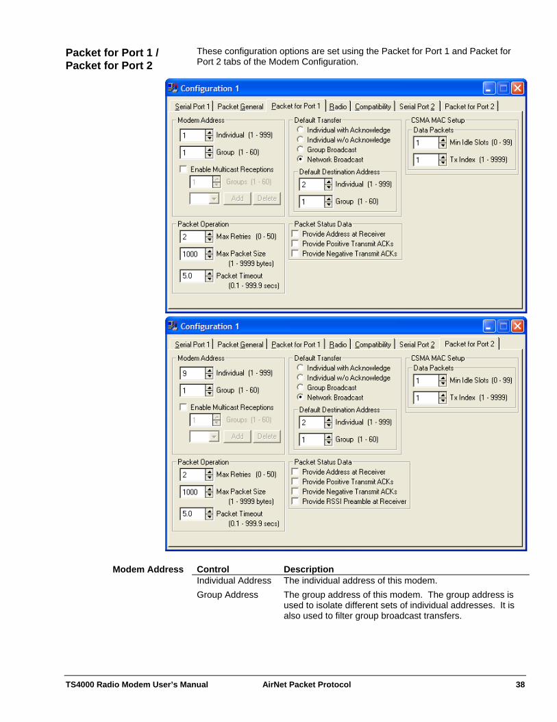
TS4000 Radio Modem User’s Manual AirNet Packet Protocol 38
These configuration options are set using the Packet for Port 1 and Packet for Port 2 tabs of the Modem Configuration.
Packet for Port 1 / Packet for Port 2
Control Description Individual Address The individual address of this modem. Group Address The group address of this modem. The group address is
used to isolate different sets of individual addresses. It is also used to filter group broadcast transfers.
Modem Address
TS4000 Radio Modem User’s Manual AirNet Packet Protocol 39
Modem Addresses of the two ports The Modem Addresses of the two ports can be the same or different. If the addresses are set the same then receive packets addressed for the modem will be sent out of both serial ports. If the addresses are different then the data coming out of the serial ports can be separated by address. Multicast groups allow a modem to receive group broadcasts to groups other than its own. This allows modems to be combined in subsets and supersets of their basic groups.
Multicast Group Reception
Control Description Enable Multicast Reception
This control enables the multicast capability of the modem and also enables the entry of multicast groups.
Multicast Groups This control is a list of multicast addresses. These addresses have the same range as the group addresses. The user can use as few or as many (up to the list size) multicast groups as desired.
By default, a modem accepts two kinds of broadcasts.
Network broadcasts are received by all modems. Group broadcasts are received by modems with the same group address as
the transmitting modem. Control Description Max Retries This control sets the maximum number of transmit retries.
A retry is attempted if a packet is sent and an acknowledge packet is not received within the time defined by the packet timeout control. After the maximum number of retries have been attempted the packet is cleared from the transmit buffer. Retries do not apply to any kind of broadcast transfers or individual transfers without acknowledgment.
Max Packet Size This control defines the maximum packet size in bytes. Any burst that is larger than this number of bytes will be broken up into multiple packets with this maximum packet size. Note that there is a difference between bytes and asynchronous characters. A byte is always eight bits of data. The number of bits in an asynchronous character is dependent on the setting of the asynchronous character control fields.
Packet Timeout The packet timeout is the amount of time the modem waits for an acknowledgment before re-sending a packet (see Network Setup - Setting Packet Timeout).
Packet Operation
TS4000 Radio Modem User’s Manual AirNet Packet Protocol 40
This field selects the type of transfer that the modem defaults to at power up. This will remain as the transfer type until it is switched using the appropriate control string.
Default Transfer
Selection Description Individual Transfer This is a standard point to point data transfer with
acknowledgments. Individual Transfer w/o Acknowledge
This is a point to point data transfer but without any acknowledgments. This implies that there are no transmit retries if the packet is received with errors.
Group Broadcast This is a broadcast to a group of modems. Receiving modems will accept two types of group broadcasts.
Group broadcasts - Broadcasts where the destination group matches the receiving modem's group.
Multicast broadcasts - Broadcasts where the destination group matches a group from the receive modem's multicast group list. For these broadcasts to be received, the receiving modem must have multicast reception enabled.
Network Broadcast
This is a broadcast to all modems.
These fields select the default destination address that the modem defaults to at power up. This address will remain as the default until it is switched using the appropriate control strings.
Default Destination Address
Type Description Individual Address The default destination individual address. Group Address The default destination group address.
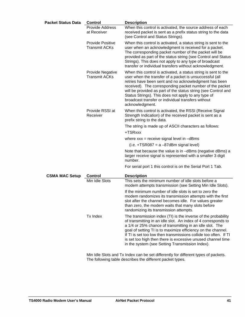
TS4000 Radio Modem User’s Manual AirNet Packet Protocol 41
Control Description Provide Address at Receiver
When this control is activated, the source address of each received packet is sent as a prefix status string to the data (see Control and Status Strings).
Provide Positive Transmit ACKs
When this control is activated, a status string is sent to the user when an acknowledgment is received for a packet. The corresponding packet number of the packet will be provided as part of the status string (see Control and Status Strings). This does not apply to any type of broadcast transfer or individual transfers without acknowledgment.
Provide Negative Transmit ACKs
When this control is activated, a status string is sent to the user when the transfer of a packet is unsuccessful (all retries have been sent and no acknowledgment has been received). The corresponding packet number of the packet will be provided as part of the status string (see Control and Status Strings). This does not apply to any type of broadcast transfer or individual transfers without acknowledgment.
Provide RSSI at Receiver
When this control is activated, the RSSI (Receive Signal Strength Indication) of the received packet is sent as a prefix string to the data. The string is made up of ASCII characters as follows: +TSRxxx where xxx = receive signal level in –dBms (i.e. +TSR087 = a –87dBm signal level) Note that because the value is in –dBms (negative dBms) a larger receive signal is represented with a smaller 3 digit number. For serial port 1 this control is on the Serial Port 1 Tab.
Packet Status Data
Control Description Min Idle Slots This sets the minimum number of idle slots before a
modem attempts transmission (see Setting Min Idle Slots). If the minimum number of idle slots is set to zero the modem randomizes its transmission attempts with the first slot after the channel becomes idle. For values greater than zero, the modem waits that many slots before randomizing its transmission attempts.
Tx Index The transmission index (TI) is the inverse of the probability of transmitting in an idle slot. An index of 4 corresponds to a 1/4 or 25% chance of transmitting in an idle slot. The goal of setting TI is to maximize efficiency on the channel. If TI is set too low then transmissions collide too often. If TI is set too high then there is excessive unused channel time in the system (see Setting Transmission Index).
CSMA MAC Setup
Min Idle Slots and Tx Index can be set differently for different types of packets. The following table describes the different packet types.

TS4000 Radio Modem User’s Manual AirNet Packet Protocol 42
Type Description Data Packets These are any packets that carry user data. These include
data packets for all the different types of transfers (i.e. Individual, Individual w/o ACK, Broadcast).
ACK Packets These are the acknowledgment packets for the individually addressed data packets.
Relay Packets These are any packets that are repeated with the store and forward repeater option. Both data packets and ACK packets can be repeated. These values are set on the Packet General tab.
Control strings are used to control the operation of the modem. Status strings are used to provide status information from the modem. Status strings from the modem can be disabled if they are not needed for a given application. All control and status strings begin with the ASCII string “+TS”, followed by specific ASCII letters and numbers corresponding to the particular control field or status value provided (See Appendix B - ASCII Character Set).
Control and Status Strings
All numbers are formatted as ASCII digits and sent most significant digit first. iii - Represents a three digit individual address. gg - Represents a two digit group address. nn - Represents a two digit packet number. Control String Description +TSI Set for individual transfer. +TSIAiii Set for individual transfer with address change. The three
address characters change the individual destination address.
+TSICggiii Set for individual transfer with complete address change. The first two characters are for the group address and the remaining three are for the individual destination address.
+TSN Set for individual without acknowledgment transfer. +TSNAiii Set for individual without acknowledgment transfer with
address change. The three address characters change the individual destination address.
+TSNCggiii Set for individual without acknowledgment transfer with complete address change. The first two characters are for the group address and the remaining three are for the individual destination address.
+TSG Set for group broadcast transfer. +TSGAgg Set for group broadcast transfer with address change. The
two address characters change the group destination address.
+TSB Set for a network broadcast transfer (to all modems). +TSFAggiii Change the modem destination address. The first two
address characters are for the group address and the remaining three are for the individual address. The type of transfer remains unchanged. This command will change the destination address of the serial port that the command is sent to. If serial port 2 is not enabled for data, then the command will always change the serial port 1 destination address regardless of which
Control Strings

TS4000 Radio Modem User’s Manual AirNet Packet Protocol 43
Control String Description port it is sent to.
+TSFA? Query the modem destination address. Response: +TSFAggiii
+TSSnn Set the packet number of the next packet transmitted. Packet numbers are used in status strings to indicate the success or failure of the transmission of a particular transmit packet. The packet number is set to 0 when the modem is reset.
+TSLAggiii Change the modem source address. The first two address characters are for the group address and the remaining three are for the individual address. This command will change the source address of the serial port that the command is sent to. If serial port 2 is not enabled for data, then the command will always change the serial port 1 source address regardless of which port it is sent to.
+TSLA? Query the modem source address. Response: +TSLAggiii
Status String Description +TSIAggiii Received an individual packet from this address. The first
two address characters represent the group address and the next three the individual address.
+TSNAggiii Received an individual without acknowledgment packet from this address. The first two address characters represent the group address and the next three the individual address.
+TSGAggiii Received a group broadcast packet from this address. The first two address characters represent the group address and the next three the individual address.
+TSBAggiii Received a network broadcast packet from this address. The first two address characters represent the group address and the next three the individual address.
+TSSFnn Indicates that the transfer of this packet number was not successful. This status string is returned after the last retry of this packet has timed out. This does not apply to any type of broadcast packet or individual without acknowledgment packets.
+TSSPnn Indicates that the transfer of this packet number was successful. This does not apply to any type of broadcast packet or individual without acknowledgment packets.
Status Strings
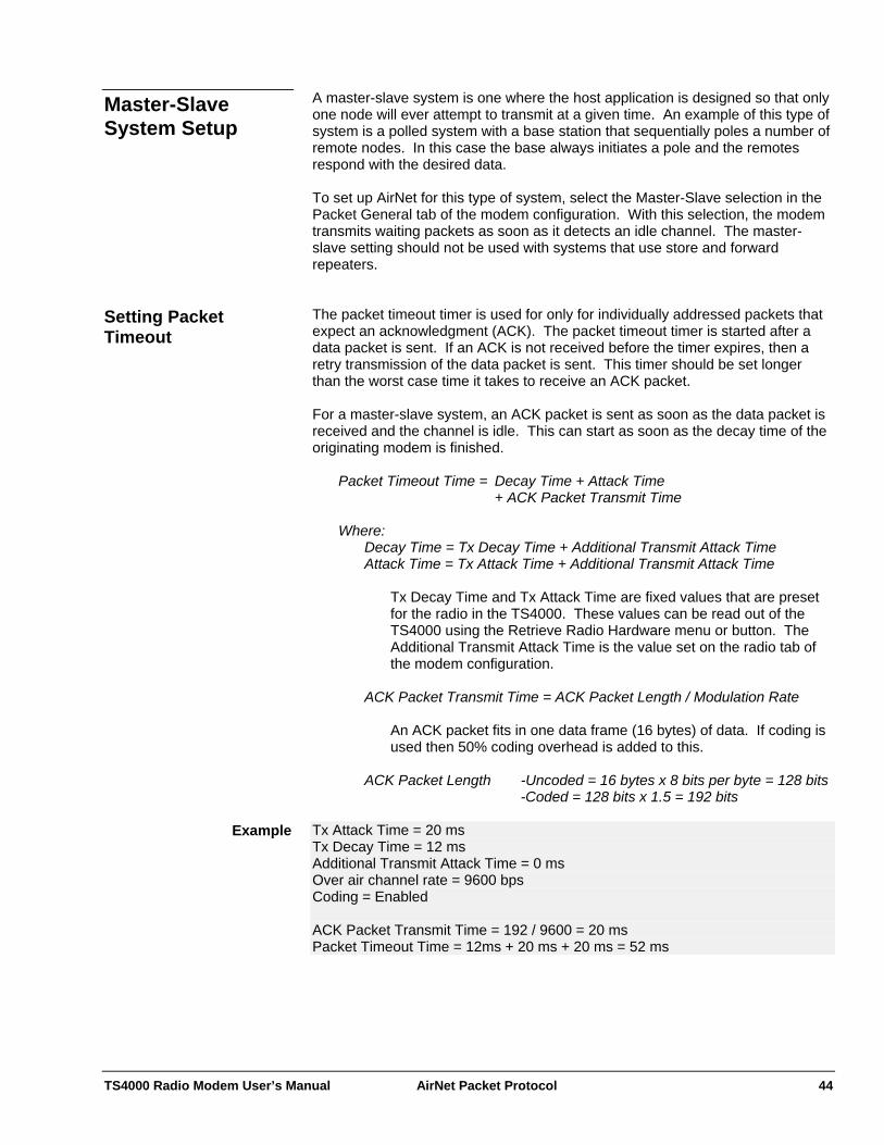
TS4000 Radio Modem User’s Manual AirNet Packet Protocol 44
A master-slave system is one where the host application is designed so that only one node will ever attempt to transmit at a given time. An example of this type of system is a polled system with a base station that sequentially poles a number of remote nodes. In this case the base always initiates a pole and the remotes respond with the desired data.
Master-Slave System Setup
To set up AirNet for this type of system, select the Master-Slave selection in the Packet General tab of the modem configuration. With this selection, the modem transmits waiting packets as soon as it detects an idle channel. The master-slave setting should not be used with systems that use store and forward repeaters. The packet timeout timer is used for only for individually addressed packets that expect an acknowledgment (ACK). The packet timeout timer is started after a data packet is sent. If an ACK is not received before the timer expires, then a retry transmission of the data packet is sent. This timer should be set longer than the worst case time it takes to receive an ACK packet.
Setting Packet Timeout
For a master-slave system, an ACK packet is sent as soon as the data packet is received and the channel is idle. This can start as soon as the decay time of the originating modem is finished. Packet Timeout Time = Decay Time + Attack Time + ACK Packet Transmit Time Where:
Decay Time = Tx Decay Time + Additional Transmit Attack Time Attack Time = Tx Attack Time + Additional Transmit Attack Time
Tx Decay Time and Tx Attack Time are fixed values that are preset for the radio in the TS4000. These values can be read out of the TS4000 using the Retrieve Radio Hardware menu or button. The Additional Transmit Attack Time is the value set on the radio tab of the modem configuration.
ACK Packet Transmit Time = ACK Packet Length / Modulation Rate
An ACK packet fits in one data frame (16 bytes) of data. If coding is used then 50% coding overhead is added to this.
ACK Packet Length -Uncoded = 16 bytes x 8 bits per byte = 128 bits
-Coded = 128 bits x 1.5 = 192 bits Tx Attack Time = 20 ms Example Tx Decay Time = 12 ms Additional Transmit Attack Time = 0 ms Over air channel rate = 9600 bps Coding = Enabled ACK Packet Transmit Time = 192 / 9600 = 20 ms Packet Timeout Time = 12ms + 20 ms + 20 ms = 52 ms
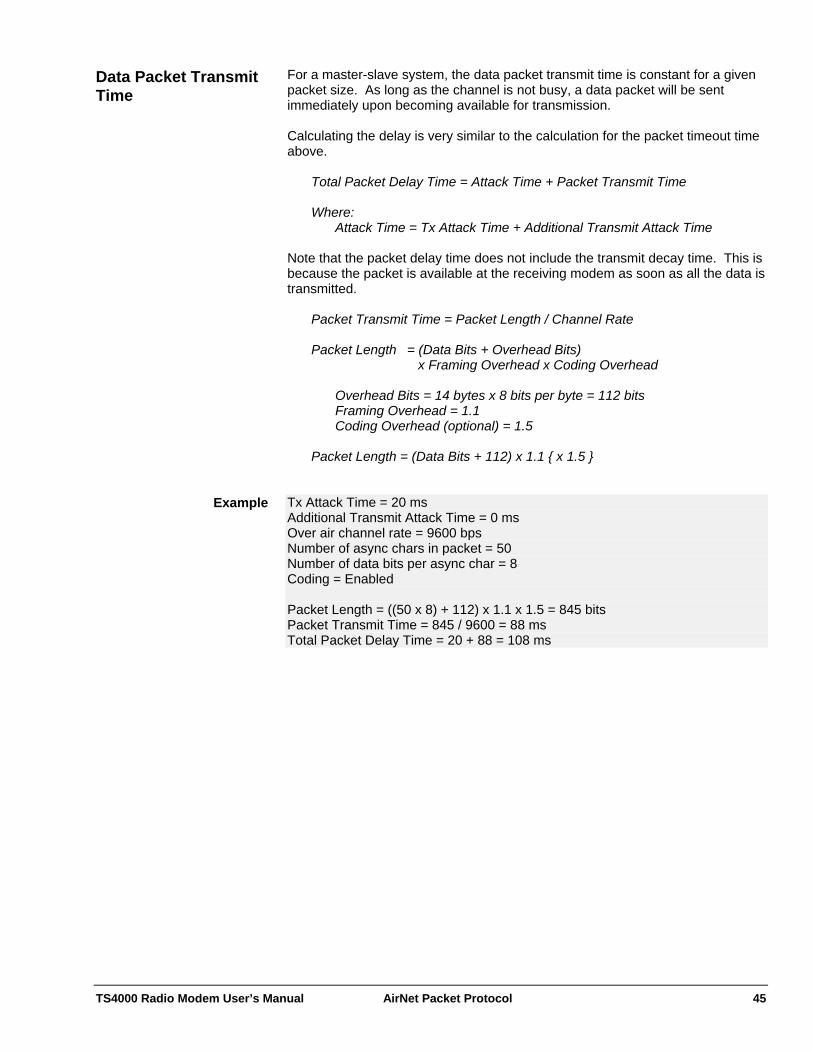
TS4000 Radio Modem User’s Manual AirNet Packet Protocol 45
For a master-slave system, the data packet transmit time is constant for a given packet size. As long as the channel is not busy, a data packet will be sent immediately upon becoming available for transmission.
Data Packet Transmit Time
Calculating the delay is very similar to the calculation for the packet timeout time above. Total Packet Delay Time = Attack Time + Packet Transmit Time Where:
Attack Time = Tx Attack Time + Additional Transmit Attack Time Note that the packet delay time does not include the transmit decay time. This is because the packet is available at the receiving modem as soon as all the data is transmitted. Packet Transmit Time = Packet Length / Channel Rate Packet Length = (Data Bits + Overhead Bits) x Framing Overhead x Coding Overhead Overhead Bits = 14 bytes x 8 bits per byte = 112 bits Framing Overhead = 1.1 Coding Overhead (optional) = 1.5 Packet Length = (Data Bits + 112) x 1.1 { x 1.5 } Tx Attack Time = 20 ms Example Additional Transmit Attack Time = 0 ms Over air channel rate = 9600 bps Number of async chars in packet = 50 Number of data bits per async char = 8 Coding = Enabled Packet Length = ((50 x 8) + 112) x 1.1 x 1.5 = 845 bits Packet Transmit Time = 845 / 9600 = 88 ms Total Packet Delay Time = 20 + 88 = 108 ms
TS4000 Radio Modem User’s Manual AirNet Packet Protocol 46
A polled system is one where a master (or base) station unit polls a number of remotes in sequence. The master is always the unit that initiates the communication and one and only one remote unit responds to the master’s request. This type of system is very common for SCADA (Supervisory Control and Data Acquisition) and telemetry systems
Polled System with Store and Forward Repeaters
Polled systems are relatively easy to configure and test because the order of communication is predictable and therefore it is possible to eliminate collisions. The following section will show a number of system topologies and the appropriate settings for the TS4000. All of these systems operate on a single frequency (simplex) although clear channel scan can be used. Note that the repeater TS4000s can also be connected to host devices and used as remotes. There is no forced limit to the number of repeaters that can be in a system. However, in most cases it is best to use the fewest repeaters possible. Each additional repeater will add complexity and delay to the system.

TS4000 Radio Modem User’s Manual AirNet Packet Protocol 47
A single repeater system is one where all communication goes through a single store and forward repeater.
Single Repeater System
Polling HostBase
Remote
Repeater
Remote
Remote
Remote
BlindRemote
BlindRemote
Configuration Parameter Setting All Units Enable Packet Operation Checked Medium Access Control (MAC) CSMA Store and Forward Repeater Operation: Repeater Filtering Address Default Transfer Network Broadcast CSMA MAC Setup: Data Packets: Tx Index 1 CSMA MAC Setup: Relay Packets: Tx Index 1 Modem Address: Group 1 Base Site Modem Address: Individual 1 CSMA MAC Setup: Data Pkts: Min Idle Slots 2 Repeater Site Modem Address: Individual 2 CSMA MAC Setup: Data Pkts: Min Idle Slots 1 CSMA MAC Setup: Relay Pkts: Min Idle Slots 0 Store and Forward Repeater Operation: All Packets Relay All Remote Sites - that hear the repeaterModem Address: Individual 10+ (each remote must have a unique
address) CSMA MAC Setup: Data Pkts: Min Idle Slots 1
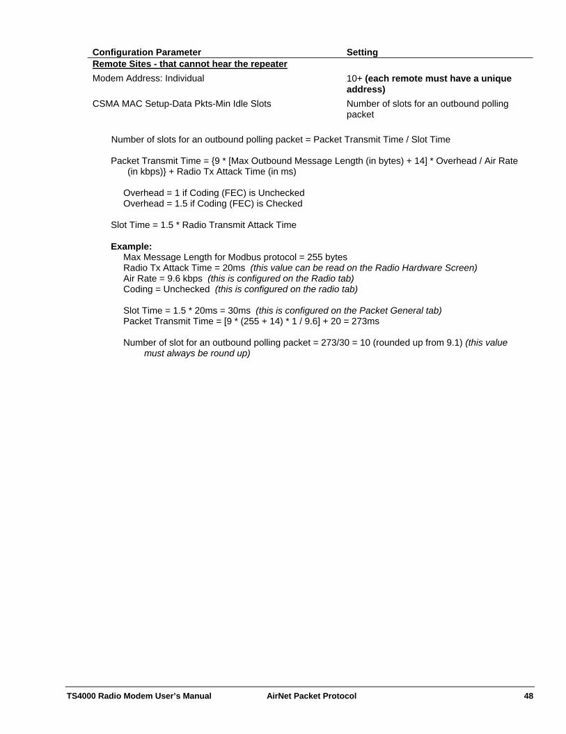
TS4000 Radio Modem User’s Manual AirNet Packet Protocol 48
Configuration Parameter Setting Remote Sites - that cannot hear the repeaterModem Address: Individual 10+ (each remote must have a unique
address) CSMA MAC Setup-Data Pkts-Min Idle Slots Number of slots for an outbound polling
packet Number of slots for an outbound polling packet = Packet Transmit Time / Slot Time
Packet Transmit Time = {9 * [Max Outbound Message Length (in bytes) + 14] * Overhead / Air Rate
(in kbps)} + Radio Tx Attack Time (in ms)
Overhead = 1 if Coding (FEC) is Unchecked Overhead = 1.5 if Coding (FEC) is Checked
Slot Time = 1.5 * Radio Transmit Attack Time
Example: Max Message Length for Modbus protocol = 255 bytes Radio Tx Attack Time = 20ms (this value can be read on the Radio Hardware Screen) Air Rate = 9.6 kbps (this is configured on the Radio tab) Coding = Unchecked (this is configured on the radio tab) Slot Time = 1.5 * 20ms = 30ms (this is configured on the Packet General tab) Packet Transmit Time = [9 * (255 + 14) * 1 / 9.6] + 20 = 273ms Number of slot for an outbound polling packet = 273/30 = 10 (rounded up from 9.1) (this value
must always be round up)

TS4000 Radio Modem User’s Manual AirNet Packet Protocol 49
A dual repeater system has two repeaters. For the specific configurations defined in this example, the two repeaters must be able to hear each other.
Dual Repeater System
Polling HostBase
Remote
Repeater B
Remote
Remote
Remote
Repeater A
Remote
Remote
Configuration Parameter Setting All Units Enable Packet Operation Checked Medium Access Control (MAC) CSMA Store and Forward Repeater Operation: Repeater Filtering Address Default Transfer Network Broadcast CSMA MAC Setup: Data Packets: Tx Index 1 CSMA MAC Setup: Relay Packets: Tx Index 1 Modem Address: Group 1 Base Site Modem Address: Individual 1 CSMA MAC Setup: Data Pkts: Min Idle Slots 3 Repeater A Site Modem Address: Individual 2 CSMA MAC Setup: Data Pkts: Min Idle Slots 2 CSMA MAC Setup: Relay Pkts: Min Idle Slots 0 Store and Forward Repeater Operation: All Packets Relay All Repeater B Site Modem Address: Individual 3 CSMA MAC Setup: Data Pkts: Min Idle Slots 2 CSMA MAC Setup: Relay Pkts: Min Idle Slots 1 Store and Forward Repeater Operation: All Packets Relay All

TS4000 Radio Modem User’s Manual AirNet Packet Protocol 50
Configuration Parameter Setting Remote Sites - that reliably hear both repeatersModem Address: Individual 10+ (each remote must have a unique
address) CSMA MAC Setup: Data Pkts: Min Idle Slots 2 Remote Sites – that hear only one of the repeatersModem Address: Individual 10+ (each remote must have a unique
address) CSMA MAC Setup: Data Pkts: Min Idle Slots Base packet transmit slots + Largest Relay
Pkt: Min Idle Slot Remote Sites – that hear only the baseModem Address: Individual 10+ (each remote must have a unique
address) CSMA MAC Setup: Data Pkts: Min Idle Slots (2 x Base packet transmit slots) + Largest
Relay Pkt: Min Idle Slot
Equations: Base packet transmit slots = Packet Transmit Time / Slot Time
Packet Transmit Time = {9 * [Max Outbound Message Length (in bytes) + 14] * Overhead / Air Rate (in
kbps)} + Radio Tx Attack Time (in ms)
Overhead = 1 if Coding (FEC) is Unchecked Overhead = 1.5 if Coding (FEC) is Checked
Slot Time = 1.5 * Radio Transmit Attack Time
Example: Remote Sites – that hear only the base:
Max Message Length for Modbus protocol = 255 bytes Radio Tx Attack Time = 20ms (this value can be read on the Radio Hardware Screen) Air Rate = 9.6 kbps (this is configured on the Radio tab) Coding = Unchecked (this is configured on the Radio tab) Largest Relay Pkt: Min Idle Slots = Repeater B: Relay Pkts: Min Idle Slots = 1 Slot Time = 1.5 * 20ms = 30ms (this is configured on the Packet General tab) Packet Transmit Time = [9 * (255 + 14) * 1 / 9.6] + 20 = 273ms Base packet transmit slots = 273/30 = 10 (rounded up from 9.1)(this value must be rounded up) CSMA MAC Setup: Data Pkts: Min Idle Slots = (2 x 10) + 1 = 21
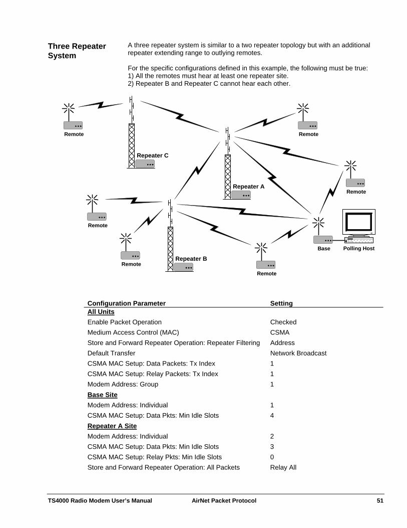
TS4000 Radio Modem User’s Manual AirNet Packet Protocol 51
A three repeater system is similar to a two repeater topology but with an additional repeater extending range to outlying remotes.
Three Repeater System
For the specific configurations defined in this example, the following must be true: 1) All the remotes must hear at least one repeater site. 2) Repeater B and Repeater C cannot hear each other.
Remote
Polling HostBase
Remote
Repeater B
Remote
Remote
Repeater A
Remote
Remote
Repeater C
Configuration Parameter Setting All Units Enable Packet Operation Checked Medium Access Control (MAC) CSMA Store and Forward Repeater Operation: Repeater Filtering Address Default Transfer Network Broadcast CSMA MAC Setup: Data Packets: Tx Index 1 CSMA MAC Setup: Relay Packets: Tx Index 1 Modem Address: Group 1 Base Site Modem Address: Individual 1 CSMA MAC Setup: Data Pkts: Min Idle Slots 4 Repeater A Site Modem Address: Individual 2 CSMA MAC Setup: Data Pkts: Min Idle Slots 3 CSMA MAC Setup: Relay Pkts: Min Idle Slots 0 Store and Forward Repeater Operation: All Packets Relay All
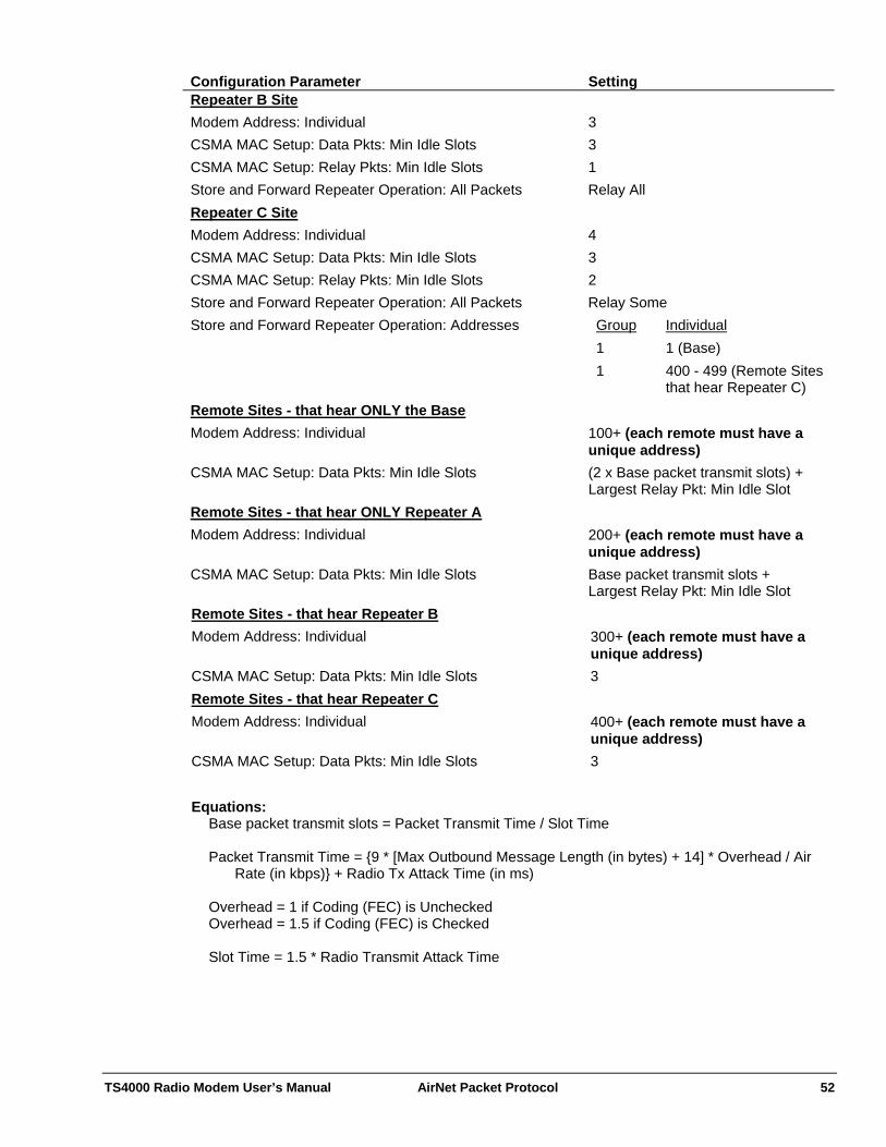
TS4000 Radio Modem User’s Manual AirNet Packet Protocol 52
Configuration Parameter Setting Repeater B Site Modem Address: Individual 3 CSMA MAC Setup: Data Pkts: Min Idle Slots 3 CSMA MAC Setup: Relay Pkts: Min Idle Slots 1 Store and Forward Repeater Operation: All Packets Relay All Repeater C Site Modem Address: Individual 4 CSMA MAC Setup: Data Pkts: Min Idle Slots 3 CSMA MAC Setup: Relay Pkts: Min Idle Slots 2 Store and Forward Repeater Operation: All Packets Relay Some Store and Forward Repeater Operation: Addresses
Group Individual1 1 (Base) 1 400 - 499 (Remote Sites
that hear Repeater C) Remote Sites - that hear ONLY the BaseModem Address: Individual 100+ (each remote must have a
unique address) CSMA MAC Setup: Data Pkts: Min Idle Slots (2 x Base packet transmit slots) +
Largest Relay Pkt: Min Idle Slot Remote Sites - that hear ONLY Repeater AModem Address: Individual 200+ (each remote must have a
unique address) CSMA MAC Setup: Data Pkts: Min Idle Slots Base packet transmit slots +
Largest Relay Pkt: Min Idle Slot Remote Sites - that hear Repeater BModem Address: Individual 300+ (each remote must have a
unique address) CSMA MAC Setup: Data Pkts: Min Idle Slots 3 Remote Sites - that hear Repeater CModem Address: Individual 400+ (each remote must have a
unique address) CSMA MAC Setup: Data Pkts: Min Idle Slots 3 Equations:
Base packet transmit slots = Packet Transmit Time / Slot Time Packet Transmit Time = {9 * [Max Outbound Message Length (in bytes) + 14] * Overhead / Air
Rate (in kbps)} + Radio Tx Attack Time (in ms) Overhead = 1 if Coding (FEC) is Unchecked Overhead = 1.5 if Coding (FEC) is Checked Slot Time = 1.5 * Radio Transmit Attack Time
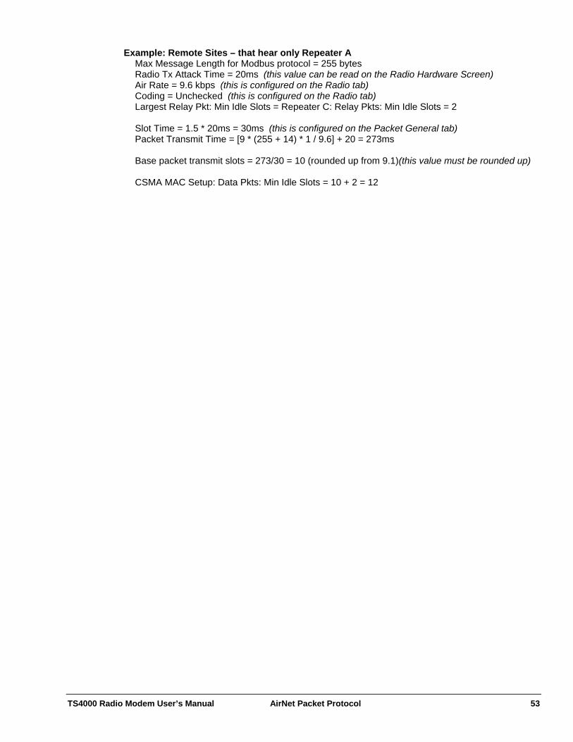
TS4000 Radio Modem User’s Manual AirNet Packet Protocol 53
Example: Remote Sites – that hear only Repeater A Max Message Length for Modbus protocol = 255 bytes Radio Tx Attack Time = 20ms (this value can be read on the Radio Hardware Screen) Air Rate = 9.6 kbps (this is configured on the Radio tab) Coding = Unchecked (this is configured on the Radio tab) Largest Relay Pkt: Min Idle Slots = Repeater C: Relay Pkts: Min Idle Slots = 2 Slot Time = 1.5 * 20ms = 30ms (this is configured on the Packet General tab) Packet Transmit Time = [9 * (255 + 14) * 1 / 9.6] + 20 = 273ms Base packet transmit slots = 273/30 = 10 (rounded up from 9.1)(this value must be rounded up) CSMA MAC Setup: Data Pkts: Min Idle Slots = 10 + 2 = 12
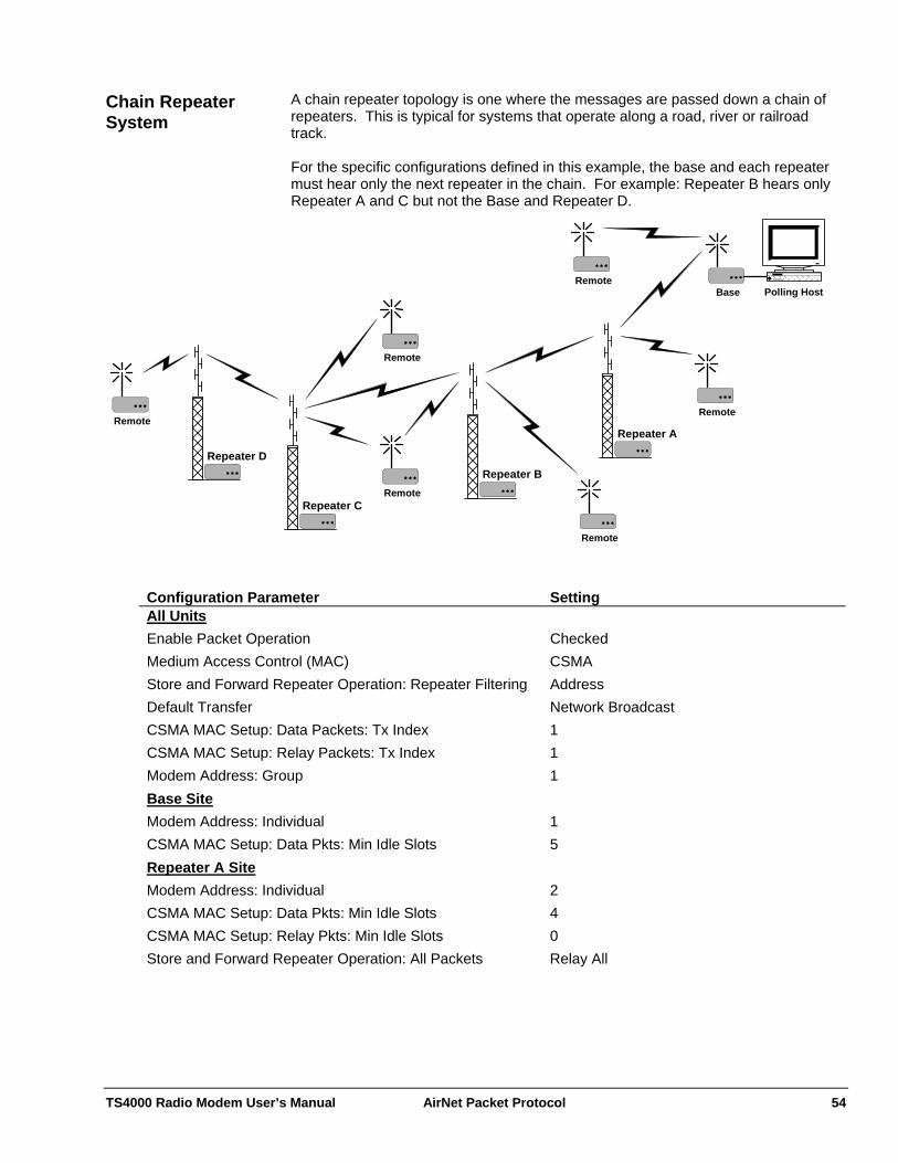
TS4000 Radio Modem User’s Manual AirNet Packet Protocol 54
A chain repeater topology is one where the messages are passed down a chain of repeaters. This is typical for systems that operate along a road, river or railroad track.
Chain Repeater System
For the specific configurations defined in this example, the base and each repeater must hear only the next repeater in the chain. For example: Repeater B hears only Repeater A and C but not the Base and Repeater D.
RemotePolling HostBase
Repeater B
Remote
Remote
Repeater A
Remote
Remote
Repeater C
Repeater D
Remote
Configuration Parameter Setting All Units Enable Packet Operation Checked Medium Access Control (MAC) CSMA Store and Forward Repeater Operation: Repeater Filtering Address Default Transfer Network Broadcast CSMA MAC Setup: Data Packets: Tx Index 1 CSMA MAC Setup: Relay Packets: Tx Index 1 Modem Address: Group 1 Base Site Modem Address: Individual 1 CSMA MAC Setup: Data Pkts: Min Idle Slots 5 Repeater A Site Modem Address: Individual 2 CSMA MAC Setup: Data Pkts: Min Idle Slots 4 CSMA MAC Setup: Relay Pkts: Min Idle Slots 0 Store and Forward Repeater Operation: All Packets Relay All
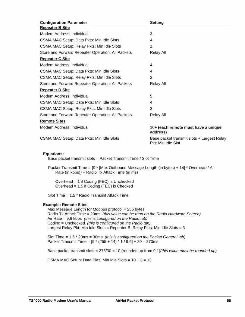
TS4000 Radio Modem User’s Manual AirNet Packet Protocol 55
Configuration Parameter Setting Repeater B Site Modem Address: Individual 3 CSMA MAC Setup: Data Pkts: Min Idle Slots 4 CSMA MAC Setup: Relay Pkts: Min Idle Slots 1 Store and Forward Repeater Operation: All Packets Relay All Repeater C Site Modem Address: Individual 4 CSMA MAC Setup: Data Pkts: Min Idle Slots 4 CSMA MAC Setup: Relay Pkts: Min Idle Slots 2 Store and Forward Repeater Operation: All Packets Relay All Repeater D Site Modem Address: Individual 5 CSMA MAC Setup: Data Pkts: Min Idle Slots 4 CSMA MAC Setup: Relay Pkts: Min Idle Slots 3 Store and Forward Repeater Operation: All Packets Relay All Remote SitesModem Address: Individual 10+ (each remote must have a unique
address) CSMA MAC Setup: Data Pkts: Min Idle Slots Base packet transmit slots + Largest Relay
Pkt: Min Idle Slot
Equations: Base packet transmit slots = Packet Transmit Time / Slot Time
Packet Transmit Time = {9 * [Max Outbound Message Length (in bytes) + 14] * Overhead / Air
Rate (in kbps)} + Radio Tx Attack Time (in ms)
Overhead = 1 if Coding (FEC) is Unchecked Overhead = 1.5 if Coding (FEC) is Checked
Slot Time = 1.5 * Radio Transmit Attack Time
Example: Remote Sites
Max Message Length for Modbus protocol = 255 bytes Radio Tx Attack Time = 20ms (this value can be read on the Radio Hardware Screen) Air Rate = 9.6 kbps (this is configured on the Radio tab) Coding = Unchecked (this is configured on the Radio tab) Largest Relay Pkt: Min Idle Slots = Repeater B: Relay Pkts: Min Idle Slots = 3 Slot Time = 1.5 * 20ms = 30ms (this is configured on the Packet General tab) Packet Transmit Time = [9 * (255 + 14) * 1 / 9.6] + 20 = 273ms Base packet transmit slots = 273/30 = 10 (rounded up from 9.1)(this value must be rounded up) CSMA MAC Setup: Data Pkts: Min Idle Slots = 10 + 3 = 13
TS4000 Radio Modem User’s Manual AirNet Packet Protocol 56
The TS4000 is very versatile and can be configured for virtually any system topology. If one of the above topologies cannot be adapted to match a particular network then Teledesign can work with you to create a suitable configuration.
Other System Topologies
The TS4000 also has the capability to selectively repeat messages from groups or individual remotes. This feature can be used to allow for more complicated topologies and to minimize the throughput delay. The following questions will need to be answered prior to creating a suitable configuration.
1) What sites (base, repeater and remote) can hear each other? In many cases this can be adjusted by using a directional antenna at the remotes and pointing them appropriately.
2) What is the maximum message size of the polling message outbound from the base site to the remotes?
3) What is the maximum message size of the response message inbound from the remotes to the base site?

TS4000 Radio Modem User’s Manual AirNet Packet Protocol 57
The CSMA MAC (Medium Access Control) is used for systems in which multiple modems will attempt to access the radio channel simultaneously (multi-access systems). If two modems attempt to transmit simultaneously, a collision results which prevents both transmissions from being successfully sent. The AirNet protocol uses CSMA/CA (Carrier Sense Multiple Access with Collision Avoidance) to provide multi-access capability. The CSMA refers to monitoring the channel to ensure that it is unused before transmitting a packet.
CSMA System Setup
Collision Avoidance For multi-access radio systems CSMA alone is typically not enough to prevent excessive collisions. The problem occurs when one modem is transmitting and multiple other modems receive data for their hosts and become ready to transmit. These other modems will wait until the first modem finishes its transmission and then they will all attempt to transmit simultaneously, resulting in a collision. This creates the need for collision avoidance. The AirNet protocol provides this by having modems randomize their transmissions once they detect an idle channel. In each slot after a modem detects an idle channel, it will decide with some probability (based on the Transmission Index) whether or not to transmit. This does not eliminate collisions, but, if the probability is set correctly, minimizes the collisions to allow for efficient multi-access use of the radio channel. Slot Time The AirNet protocol uses timing slots to determine when to attempt transmissions. These slots are slightly different from the slots used in conventional multi-access slotted MACs. The AirNet slots are the minimum channel detection times or the minimum time from when one modem begins transmission to when all other modems will detect that transmission. This size slot guarantees that modems waiting to transmit in consecutive slots will not collide and allows for very efficient use of the radio channel. The following is a summary of the suggested settings for a basic CSMA system. A basic system does not have any store and forward repeaters. Note that more detail on the parameters and equations can be found later in this section.
Basic System - Setup Summary
Slot Time = Attack Time + Maximum Carrier Detect Time Variation Slot Time = 1.5 x Attack Time Where:
Attack Time = Radio Attack Time + Additional Transmit Attack Time
Tx Decay Time and Tx Attack Time are fixed values that are preset for the radio in the TS4000. These values can be read out of the TS4000 using the Retrieve Radio Hardware menu or button. The Additional Transmit Attack Time is the value set on the radio tab of the modem configuration.
Min Idle Slots - ACK Packets = 0 Min Idle Slots Min Idle Slots - Data Packets = 1 Tx Index - ACK Packets = 1 Tx Index Tx Index - Data Packets = Estimated Backlogged Nodes / Attempt Rate Where: Attempt Rate = (Packet Detection Ratio)1/2
Packet Detection Ratio = Slot Time / Total Packet Time Total Packet Time = Attack Time + Packet Transmit Time + Decay Time

TS4000 Radio Modem User’s Manual AirNet Packet Protocol 58
Packet Transmit Time = Packet Length / Channel Rate Packet Length = (Data Bits + Overhead Bits) x Framing Overhead x Coding Overhead = (Data Bits + 112) x 1.1 { x 1.5 } Overhead Bits = 14 bytes x 8 bits per byte = 112 bits Framing Overhead = 1.1 Coding Overhead (optional) = 1.5 Packet Timeout = Decay Time + Attack Time + ACK Packet Transmit Time Packet Timeout Where:
Decay Time = Tx Decay Time + Additional Transmit Attack Time Attack Time = Tx Attack Time + Additional Transmit Attack Time
ACK Packet Transmit Time = ACK Packet Length / Channel Rate
ACK Packet Length -Uncoded = 16 bytes x 8 bits per byte = 128 bits -Coded = 128 bits x 1.5 = 192 bits The following is a summary of the suggested settings for a system that has one or more store and forward repeaters. Note that more detail on the parameters and equations can be found later in this section.
System with Repeaters - Setup Summary
Slot Time = Attack Time + Maximum Carrier Detect Time Variation Slot Time = 1.5 x Attack Time Where:
Attack Time = Radio Attack Time + Additional Transmit Attack Time
Tx Decay Time and Tx Attack Time are fixed values that are preset for the radio in the TS4000. These values can be read out of the TS4000 using the Retrieve Radio Hardware menu or button. The Additional Transmit Attack Time is the value set on the radio tab of the modem configuration.
Min Idle Slots - ACK Packets = 0 Min Idle Slots Min Idle Slots - Relay Packets (Relay #1) = 1 Min Idle Slots - Relay Packets (Relay #2) = 2 ... ... Min Idle Slots - Relay Packets (Relay #Z) = Z Min Idle Slots - Data Packets = Highest Relay # + 1 = Z + 1 Tx Index - ACK Packets = 1 Tx Index Tx Index - Relay Packets = 1 Tx Index - Data Packets = Estimated Backlogged Nodes / Attempt Rate Where: Estimated Backlogged Nodes (number of nodes that simultaneously want to transmit) = the greater of A) Average Number of Backlogged Nodes or B) 1/4 Maximum Possible Number of Backlogged Nodes Attempt Rate = (Packet Detection Ratio)1/2
Packet Detection Ratio = Slot Time / Total Packet Time
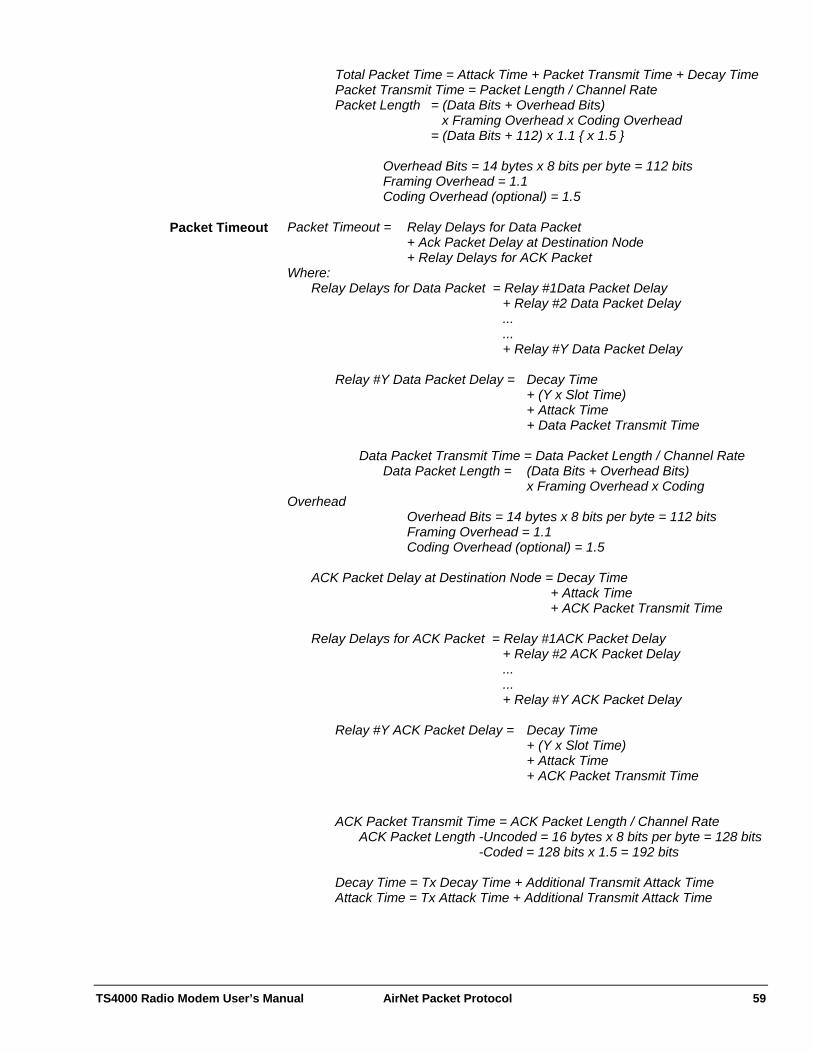
TS4000 Radio Modem User’s Manual AirNet Packet Protocol 59
Total Packet Time = Attack Time + Packet Transmit Time + Decay Time Packet Transmit Time = Packet Length / Channel Rate Packet Length = (Data Bits + Overhead Bits) x Framing Overhead x Coding Overhead = (Data Bits + 112) x 1.1 { x 1.5 } Overhead Bits = 14 bytes x 8 bits per byte = 112 bits Framing Overhead = 1.1 Coding Overhead (optional) = 1.5 Packet Timeout = Relay Delays for Data Packet Packet Timeout + Ack Packet Delay at Destination Node + Relay Delays for ACK Packet Where: Relay Delays for Data Packet = Relay #1Data Packet Delay + Relay #2 Data Packet Delay ... ... + Relay #Y Data Packet Delay Relay #Y Data Packet Delay = Decay Time + (Y x Slot Time) + Attack Time + Data Packet Transmit Time Data Packet Transmit Time = Data Packet Length / Channel Rate Data Packet Length = (Data Bits + Overhead Bits) x Framing Overhead x Coding Overhead Overhead Bits = 14 bytes x 8 bits per byte = 112 bits Framing Overhead = 1.1 Coding Overhead (optional) = 1.5 ACK Packet Delay at Destination Node = Decay Time + Attack Time + ACK Packet Transmit Time Relay Delays for ACK Packet = Relay #1ACK Packet Delay + Relay #2 ACK Packet Delay ... ... + Relay #Y ACK Packet Delay Relay #Y ACK Packet Delay = Decay Time + (Y x Slot Time) + Attack Time + ACK Packet Transmit Time ACK Packet Transmit Time = ACK Packet Length / Channel Rate ACK Packet Length -Uncoded = 16 bytes x 8 bits per byte = 128 bits -Coded = 128 bits x 1.5 = 192 bits
Decay Time = Tx Decay Time + Additional Transmit Attack Time Attack Time = Tx Attack Time + Additional Transmit Attack Time

TS4000 Radio Modem User’s Manual AirNet Packet Protocol 60
The slot time should be set to the attack time of the radio plus the maximum variation (uncertainty) in the carrier detection circuit. The variation in the carrier detection circuit is the difference in the carrier detect time between the radio with the fastest carrier detect time and the radio with the slowest carrier detect time. Note that the attack time is made up of the worst case transmitter power ramp up time plus the worst case carrier detect time. Typically the maximum variation of the carrier detect circuit is less than half (50%) of the attack time.
Setting Slot Time
Slot Time = Attack Time + Maximum Carrier Detect Time Variation = 1.5 x Attack Time
Attack Time = Tx Attack Time + Additional Transmit Attack Time Tx Attack Time is a fixed value that is preset for the radio in the TS4000. This value can be read out of the TS4000 using the Retrieve Radio Hardware menu or button. The Additional Transmit Attack Time is the value set on the radio tab of the modem configuration.
The minimum idle slot setting defines the number of slots which a modem will leave vacant after the modem detects an idle channel and before the modem attempts to transmit. A setting of 0 means that the modem will attempt transmission in the first slot after the channel becomes available (idle). A setting of 1 means that the modem will wait 1 slot after the channel is available before attempting to transmit. The number of minimum idle slots can be set differently for each packet type (data, ACK or relay).
Setting Min Idle Slots
The simplest and most efficient system setup is where ACK (acknowledgment) packets are sent immediately after a valid data packet is received. With this setup the ACK packets do not contend for the channel the way data packets do. Correspondingly, the data packets are set so that they will leave the first slot open for the ACK packets.
Systems without Repeaters
This type of setup has the advantage that the delay for receiving an ACK packet is consistent and predictable. This makes it much easier to set an appropriate packet timeout (see Setting Packet Timeout). Min Idle Slots - ACK Packets = 0 Min Idle Slots - Data Packets = 1 Tx Index - ACK Packets = 1 (Always transmit in the first slot) Tx Index - Data Packets = Attempt Rate (see Setting Tx Index) For systems with one or more relay nodes, the simplest and most efficient system setup is where each relay is assigned a particular slot. This way the repeaters do not collide or contend for the channel the way data packets do. The data packets are set so that they will leave the necessary number of slots open for the repeaters and ACK packets.
Systems with Repeaters
This type of setup has the advantage that the delay for sending data through the relay(s) is consistent and predictable. This makes it much easier to set an appropriate packet timeout (see Setting Packet Timeout).
Min Idle Slots Min Idle Slots - ACK Packets = 0 Min Idle Slots - Relay #1 = 1 Min Idle Slots - Relay #2 = 2
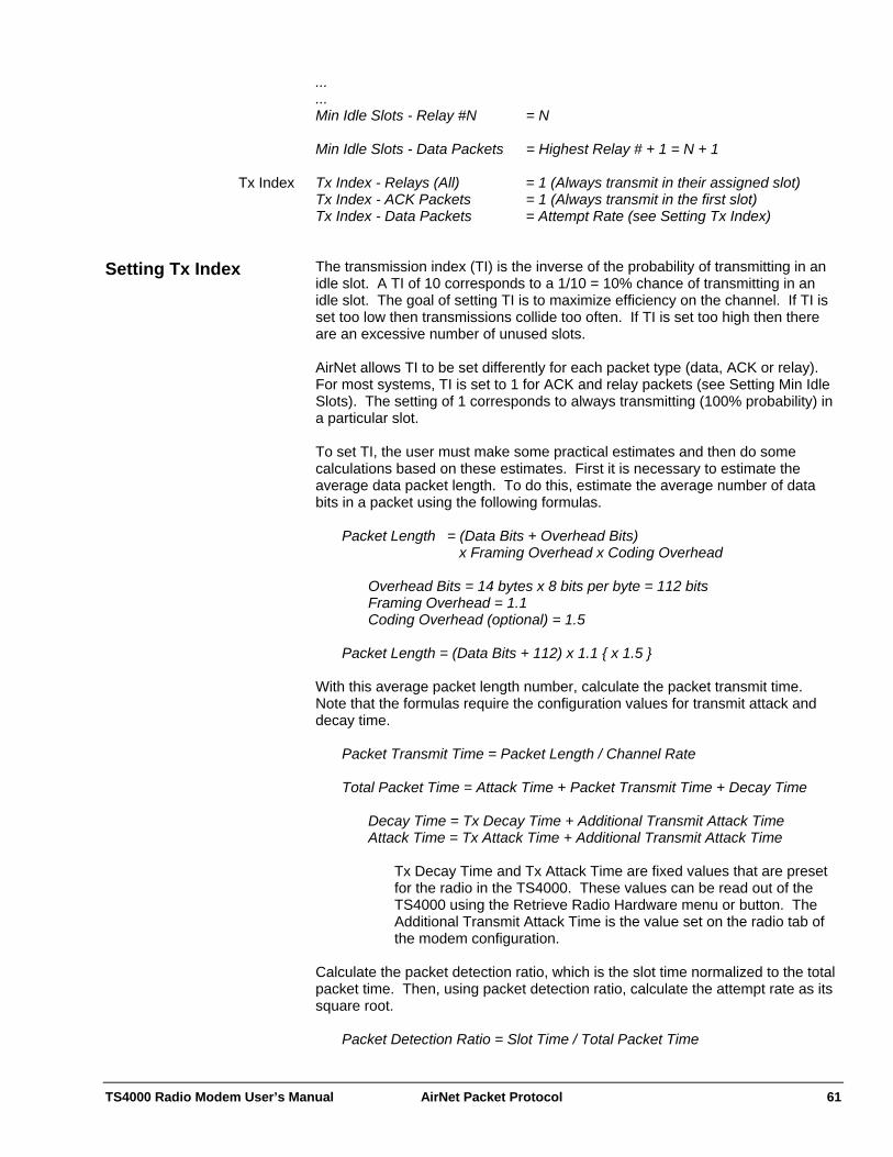
TS4000 Radio Modem User’s Manual AirNet Packet Protocol 61
...
... Min Idle Slots - Relay #N = N Min Idle Slots - Data Packets = Highest Relay # + 1 = N + 1
Tx Index Tx Index - Relays (All) = 1 (Always transmit in their assigned slot) Tx Index - ACK Packets = 1 (Always transmit in the first slot) Tx Index - Data Packets = Attempt Rate (see Setting Tx Index) The transmission index (TI) is the inverse of the probability of transmitting in an idle slot. A TI of 10 corresponds to a 1/10 = 10% chance of transmitting in an idle slot. The goal of setting TI is to maximize efficiency on the channel. If TI is set too low then transmissions collide too often. If TI is set too high then there are an excessive number of unused slots.
Setting Tx Index
AirNet allows TI to be set differently for each packet type (data, ACK or relay). For most systems, TI is set to 1 for ACK and relay packets (see Setting Min Idle Slots). The setting of 1 corresponds to always transmitting (100% probability) in a particular slot. To set TI, the user must make some practical estimates and then do some calculations based on these estimates. First it is necessary to estimate the average data packet length. To do this, estimate the average number of data bits in a packet using the following formulas. Packet Length = (Data Bits + Overhead Bits) x Framing Overhead x Coding Overhead Overhead Bits = 14 bytes x 8 bits per byte = 112 bits Framing Overhead = 1.1 Coding Overhead (optional) = 1.5 Packet Length = (Data Bits + 112) x 1.1 { x 1.5 } With this average packet length number, calculate the packet transmit time. Note that the formulas require the configuration values for transmit attack and decay time. Packet Transmit Time = Packet Length / Channel Rate Total Packet Time = Attack Time + Packet Transmit Time + Decay Time
Decay Time = Tx Decay Time + Additional Transmit Attack Time Attack Time = Tx Attack Time + Additional Transmit Attack Time
Tx Decay Time and Tx Attack Time are fixed values that are preset for the radio in the TS4000. These values can be read out of the TS4000 using the Retrieve Radio Hardware menu or button. The Additional Transmit Attack Time is the value set on the radio tab of the modem configuration.
Calculate the packet detection ratio, which is the slot time normalized to the total packet time. Then, using packet detection ratio, calculate the attempt rate as its square root. Packet Detection Ratio = Slot Time / Total Packet Time
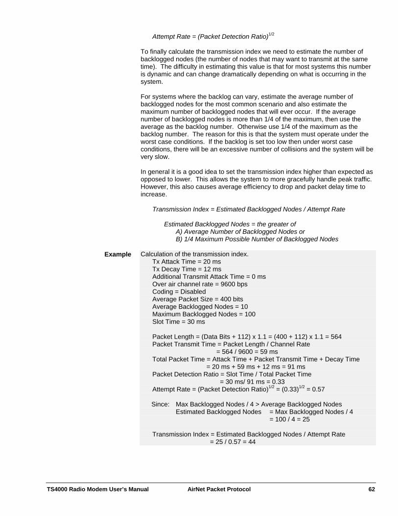
TS4000 Radio Modem User’s Manual AirNet Packet Protocol 62
Attempt Rate = (Packet Detection Ratio)1/2
To finally calculate the transmission index we need to estimate the number of backlogged nodes (the number of nodes that may want to transmit at the same time). The difficulty in estimating this value is that for most systems this number is dynamic and can change dramatically depending on what is occurring in the system. For systems where the backlog can vary, estimate the average number of backlogged nodes for the most common scenario and also estimate the maximum number of backlogged nodes that will ever occur. If the average number of backlogged nodes is more than 1/4 of the maximum, then use the average as the backlog number. Otherwise use 1/4 of the maximum as the backlog number. The reason for this is that the system must operate under the worst case conditions. If the backlog is set too low then under worst case conditions, there will be an excessive number of collisions and the system will be very slow. In general it is a good idea to set the transmission index higher than expected as opposed to lower. This allows the system to more gracefully handle peak traffic. However, this also causes average efficiency to drop and packet delay time to increase. Transmission Index = Estimated Backlogged Nodes / Attempt Rate Estimated Backlogged Nodes = the greater of A) Average Number of Backlogged Nodes or B) 1/4 Maximum Possible Number of Backlogged Nodes Calculation of the transmission index. Example
Tx Attack Time = 20 ms Tx Decay Time = 12 ms Additional Transmit Attack Time = 0 ms
Over air channel rate = 9600 bps Coding = Disabled Average Packet Size = 400 bits Average Backlogged Nodes = 10 Maximum Backlogged Nodes = 100 Slot Time = 30 ms Packet Length = (Data Bits + 112) x 1.1 = (400 + 112) x 1.1 = 564 Packet Transmit Time = Packet Length / Channel Rate = 564 / 9600 = 59 ms Total Packet Time = Attack Time + Packet Transmit Time + Decay Time = 20 ms + 59 ms + 12 ms = 91 ms Packet Detection Ratio = Slot Time / Total Packet Time = 30 ms/ 91 ms = 0.33 Attempt Rate = (Packet Detection Ratio)1/2 = (0.33)1/2 = 0.57 Since: Max Backlogged Nodes / 4 > Average Backlogged Nodes Estimated Backlogged Nodes = Max Backlogged Nodes / 4 = 100 / 4 = 25 Transmission Index = Estimated Backlogged Nodes / Attempt Rate = 25 / 0.57 = 44

TS4000 Radio Modem User’s Manual AirNet Packet Protocol 63
The packet timeout timer is used for individual packets that expect an acknowledgment (ACK). This timer is started after a data packet is sent. If an ACK is not received before the timer expires then a retry transmission of the data packet is sent. This timer should be set longer than the worst case typical amount of time it takes to receive an ACK packet.
Setting Packet Timeout
The following calculations are for systems that are setup so that ACK packets are sent immediately after the data packet transmission is completed without contending for the channel (see Setting Min Idle Slots). For this type of CSMA system the packet timeout time is the same as for a Master/Slave system. The ACK is sent as soon as the decay time of the sending modem is finished.
Systems without Repeaters
Packet Timeout Time = Decay Time + Attack Time + ACK Packet Transmit Time
Decay Time = Tx Decay Time + Additional Transmit Attack Time Attack Time = Tx Attack Time + Additional Transmit Attack Time
ACK Packet Transmit Time = ACK Packet Length / Channel Rate
An ACK packet fits in one data frame (16 bytes) of data. If coding is used, then 50 % coding overhead is added to this.
ACK Packet Length -Uncoded = 16 bytes x 8 bits per byte = 128 bits -Coded = 128 bits x 1.5 = 192 bits The following calculations are for systems that are setup as described in the Setting Min Idle Slots section. The packet timeout should be set to the amount of time it takes to send the data packet and then the amount of time it takes to get back an acknowledgement.
Systems with Repeaters
Packet Timeout = Relay Delays for Data Packet + Ack Packet Delay at Destination Node + Relay Delays for ACK Packet The amount of time it takes to send a data packet is the sum of the amount of time it takes each relay to send the data packet. Relay Delays for Data Packet = Relay #1Data Packet Delay + Relay #2 Data Packet Delay ... ... + Relay #Y Data Packet Delay The time it takes each relay to send the packet is basically the packet transmit time. Added to this must be the number of idle slots between the last transmission and when the current relay decides to transmit. Relay #Y Data Packet Delay = Decay Time + (Y x Slot Time) + Attack Time + Data Packet Transmit Time
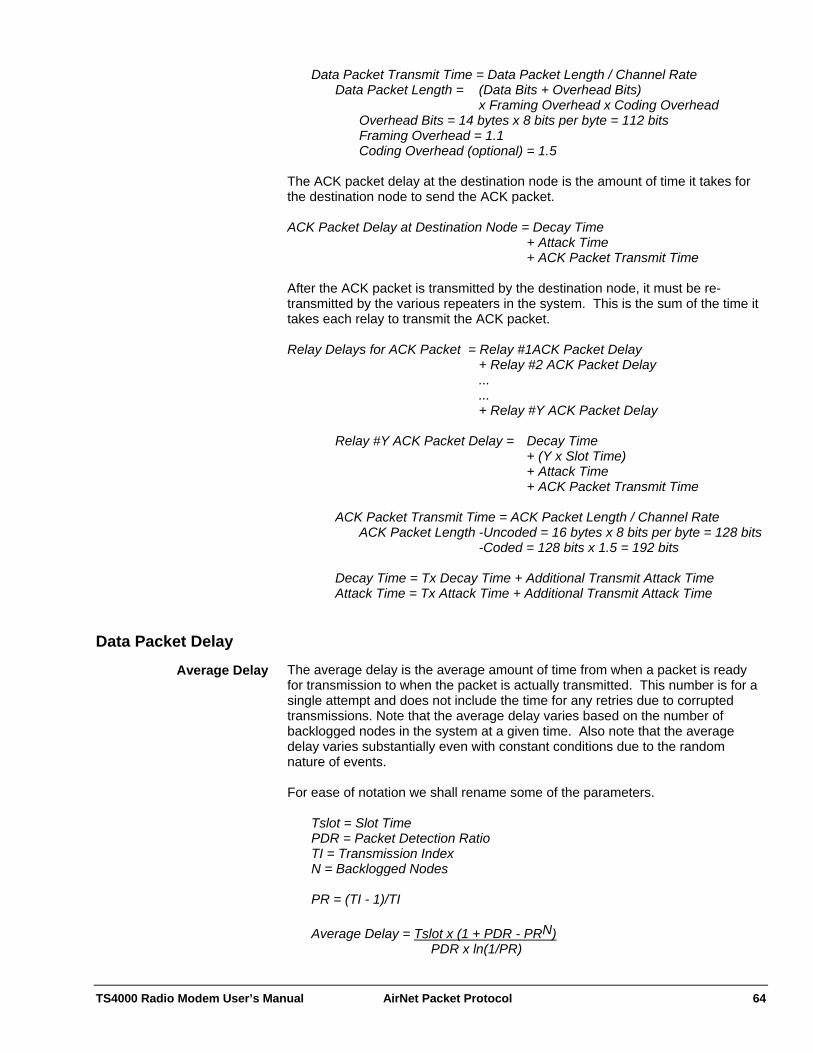
TS4000 Radio Modem User’s Manual AirNet Packet Protocol 64
Data Packet Transmit Time = Data Packet Length / Channel Rate Data Packet Length = (Data Bits + Overhead Bits) x Framing Overhead x Coding Overhead Overhead Bits = 14 bytes x 8 bits per byte = 112 bits Framing Overhead = 1.1 Coding Overhead (optional) = 1.5 The ACK packet delay at the destination node is the amount of time it takes for the destination node to send the ACK packet. ACK Packet Delay at Destination Node = Decay Time + Attack Time + ACK Packet Transmit Time After the ACK packet is transmitted by the destination node, it must be re-transmitted by the various repeaters in the system. This is the sum of the time it takes each relay to transmit the ACK packet. Relay Delays for ACK Packet = Relay #1ACK Packet Delay + Relay #2 ACK Packet Delay ... ... + Relay #Y ACK Packet Delay Relay #Y ACK Packet Delay = Decay Time + (Y x Slot Time) + Attack Time + ACK Packet Transmit Time ACK Packet Transmit Time = ACK Packet Length / Channel Rate ACK Packet Length -Uncoded = 16 bytes x 8 bits per byte = 128 bits -Coded = 128 bits x 1.5 = 192 bits
Decay Time = Tx Decay Time + Additional Transmit Attack Time Attack Time = Tx Attack Time + Additional Transmit Attack Time
Data Packet Delay The average delay is the average amount of time from when a packet is ready for transmission to when the packet is actually transmitted. This number is for a single attempt and does not include the time for any retries due to corrupted transmissions. Note that the average delay varies based on the number of backlogged nodes in the system at a given time. Also note that the average delay varies substantially even with constant conditions due to the random nature of events.
Average Delay
For ease of notation we shall rename some of the parameters. Tslot = Slot Time PDR = Packet Detection Ratio TI = Transmission Index N = Backlogged Nodes PR = (TI - 1)/TI Average Delay = Tslot x (1 + PDR - PRN) PDR x ln(1/PR)
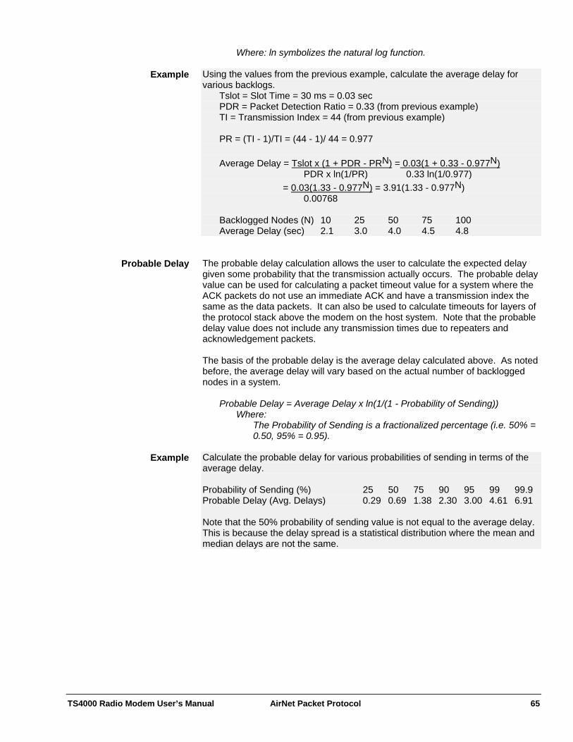
TS4000 Radio Modem User’s Manual AirNet Packet Protocol 65
Where: ln symbolizes the natural log function. Using the values from the previous example, calculate the average delay for various backlogs.
Example
Tslot = Slot Time = 30 ms = 0.03 sec PDR = Packet Detection Ratio = 0.33 (from previous example) TI = Transmission Index = 44 (from previous example) PR = (TI - 1)/TI = (44 - 1)/ 44 = 0.977 Average Delay = Tslot x (1 + PDR - PRN) = 0.03(1 + 0.33 - 0.977N) PDR x ln(1/PR) 0.33 ln(1/0.977) = 0.03(1.33 - 0.977N) = 3.91(1.33 - 0.977N) 0.00768 Backlogged Nodes (N) 10 25 50 75 100 Average Delay (sec) 2.1 3.0 4.0 4.5 4.8 The probable delay calculation allows the user to calculate the expected delay given some probability that the transmission actually occurs. The probable delay value can be used for calculating a packet timeout value for a system where the ACK packets do not use an immediate ACK and have a transmission index the same as the data packets. It can also be used to calculate timeouts for layers of the protocol stack above the modem on the host system. Note that the probable delay value does not include any transmission times due to repeaters and acknowledgement packets.
Probable Delay
The basis of the probable delay is the average delay calculated above. As noted before, the average delay will vary based on the actual number of backlogged nodes in a system.
Probable Delay = Average Delay x ln(1/(1 - Probability of Sending)) Where:
The Probability of Sending is a fractionalized percentage (i.e. 50% = 0.50, 95% = 0.95).
Calculate the probable delay for various probabilities of sending in terms of the average delay.
Example
Probability of Sending (%) 25 50 75 90 95 99 99.9 Probable Delay (Avg. Delays) 0.29 0.69 1.38 2.30 3.00 4.61 6.91 Note that the 50% probability of sending value is not equal to the average delay. This is because the delay spread is a statistical distribution where the mean and median delays are not the same.
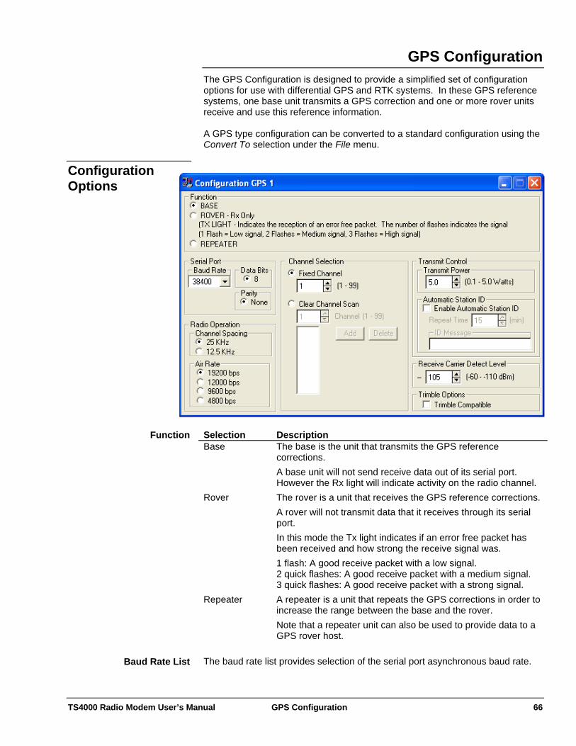
TS4000 Radio Modem User’s Manual GPS Configuration 66
GPS Configuration The GPS Configuration is designed to provide a simplified set of configuration options for use with differential GPS and RTK systems. In these GPS reference systems, one base unit transmits a GPS correction and one or more rover units receive and use this reference information. A GPS type configuration can be converted to a standard configuration using the Convert To selection under the File menu.
Configuration Options
Selection Description Base The base is the unit that transmits the GPS reference
corrections. A base unit will not send receive data out of its serial port. However the Rx light will indicate activity on the radio channel.
Rover The rover is a unit that receives the GPS reference corrections. A rover will not transmit data that it receives through its serial port. In this mode the Tx light indicates if an error free packet has been received and how strong the receive signal was. 1 flash: A good receive packet with a low signal. 2 quick flashes: A good receive packet with a medium signal. 3 quick flashes: A good receive packet with a strong signal.
Repeater A repeater is a unit that repeats the GPS corrections in order to increase the range between the base and the rover. Note that a repeater unit can also be used to provide data to a GPS rover host.
Function
The baud rate list provides selection of the serial port asynchronous baud rate. Baud Rate List

TS4000 Radio Modem User’s Manual GPS Configuration 67
This indicates the number of data bits in each asynchronous character. Data Bits This indicates the parity of the asynchronous characters. Parity Selection Description Channel Spacing
This setting should be configured to match the maximum channel spacing allowed by the user’s license. This value controls the amount of frequency bandwidth (occupied bandwidth) that the transmitted signal will use. A higher value corresponds to more bandwidth and therefore provides better BER (Bit Error Rate) performance and a higher maximum over the air data rate. 25KHz: This setting corresponds to an occupied bandwidth of 20.0KHz which is the maximum value allowed by the FCC for a 25KHz channel. 12.5KHz: This setting corresponds to an occupied bandwidth of 11.2KHz which is the maximum value allowed by the FCC for a 12.5KHz channel.
Air Rate The over the air modulation bit rate.
Radio Operation
Selection Description Fixed Channel The channel activated at power up is the channel set in the
corresponding control. Clear Channel Scan
Activates Clear Channel Scan Operation. The bottom box is the scan list which indicates the channels that will be scanned. The scan list can be changed with the channel box, add button and delete button. When Clear channel operation is enabled, the TS4000 will automatically and dynamically select the least congested channel from the clear channel scan list. This operation is completely transparent to the host equipment and does not require any operator intervention. When clear channel scan is enabled, all of the TS4000s (both transmitters and receivers) are constantly scans the channels of the scan list looking for valid TS4000 transmissions and also looking for interference (noise or transmissions from other sources). The TS4000s keeps track of the amount of interference on each channel. Before transmitting, a TS4000 will select the best channel and switch to the channel with the least amount of interference. The receiving TS4000s will then see this valid TS4000 transmission during their scans and receive the packet. To insure that receiving TS4000s have time to detect and lock up to all transmissions, the transmit preamble time is increased based on the number of channels on the scan list.
Frequency Channel at Power Up
This sets the transmit power level. The maximum transmit power that can be set depends on the specific radio module in the TS4000. Therefore the maximum value that can be set is listed only when the configuration program is connected to the TS4000.
Transmit Power
TS4000 Radio Modem User’s Manual GPS Configuration 68
The TS4000 can be configured to periodically output a Morse code identification string.
Automatic Station ID
Selection Description Enable Automatic Station ID
When the control is selected, the modem will output the ID message at the designated repeat time.
Repeat Time This is the amount of time between station ID transmissions. ID Message This is the text message that is transmitted. The
transmission is formatted as standard Morse code. This is typically set to be a station call sign, license number or location.
This sets the receive signal level at which the receiver is activated. This is similar to the squelch control on mobile radios. Normally this level is set slightly lower than the level at which the TS4000 can correctly demodulate the incoming data.
Receive Carrier Detect Level
When using the TS4000 in a high noise environment, this level can be raised so that the TS4000 is more selective about the signals that it attempts to demodulate. This is important for configurations that do not allow the TS4000 to transmit while it is receiving. These include configurations with packet operation enabled or with the Force Transmit over Receive control disabled. This mode allows the TS4000 to communicate with Trimble TrimMark and TrimTalk GPS data links.
Trimble Compatible
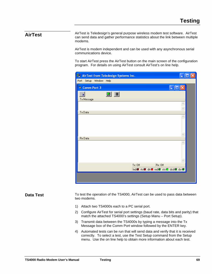
TS4000 Radio Modem User’s Manual Testing 69
Testing AirTest is Teledesign’s general purpose wireless modem test software. AirTest can send data and gather performance statistics about the link between multiple modems.
AirTest
AirTest is modem independent and can be used with any asynchronous serial communications device. To start AirTest press the AirTest button on the main screen of the configuration program. For details on using AirTest consult AirTest’s on line help.
To test the operation of the TS4000, AirTest can be used to pass data between two modems.
Data Test 1) Attach two TS4000s each to a PC serial port. 2) Configure AirTest for serial port settings (baud rate, data bits and parity) that
match the attached TS4000’s settings (Setup Manu – Port Setup). 3) Transmit data between the TS4000s by typing a message into the Tx
Message box of the Comm Port window followed by the ENTER key. 4) Automated tests can be run that will send data and verify that it is received
correctly. To select a test, use the Test Setup command from the Setup menu. Use the on line help to obtain more information about each test.
TS4000 Radio Modem User’s Manual Testing 70
A BER (Bit Error Rate) test is used to determine how good a radio environment is for transmitting data. The BER result tells the percentage of bits that are corrupted. A BER of 3.0 x 10⁻⁴ means that 3 out of 10,000 (104) bits are corrupted.
BER Test
The longer a BER test runs the more accurate the result. To get an accurate result a BER test should be run until at least 100 errors have been received. This provides a 90% confidence level in the BER value. However, in a relatively error free environment this can take a very long time. An alternative is to run the BER test until at least 10 errors have been received which provides a 68% confidence level. AirTest can be setup to run a BER test. To run a BER test, the TS4000s must be configured with packet operation disabled. This is because when the TS4000 is setup for packet operation it discards corrupted packets and does not send them out the serial port. 1) Attach two TS4000s each to a PC serial port. 2) Configure AirTest for serial port settings (baud rate, data bits and parity) that
match the attached TS4000’s settings (Setup Manu – Port Setup). 3) Select and start one of the automated tests. To select a test, use the Test
Setup command from the Setup menu. Use the on-line help for details about the different tests.
4) Observe the results by click on the Show Status button on the Comm Port window.

TS4000 Radio Modem User’s Manual Testing 71
AirScan enables the TS4000 to be used as a frequency scanner. AirScan is useful for determining the frequency and magnitude of potential interference within the TS4000’s frequency band.
AirScan
To start AirScan press the AirScan button on the main screen of the configuration program.
AirScan scans each channel within a set range of frequencies. The granularity of the scan is fixed at the minimum channel spacing of the TS4000.
AirScan Controls Selection Description Live In this mode the scanning overwrites the previous values of
signal magnitude. Peak Hold The display shows only the largest magnitude signal. Use
the Clear Screen button to reset the values.
Display
This sets the frequency in the middle of the display. Note that the frequencies at the edges of the display are also indicated.
Center Frequency
This is the frequency span from the left edge to the right edge of the display. Frequency Span
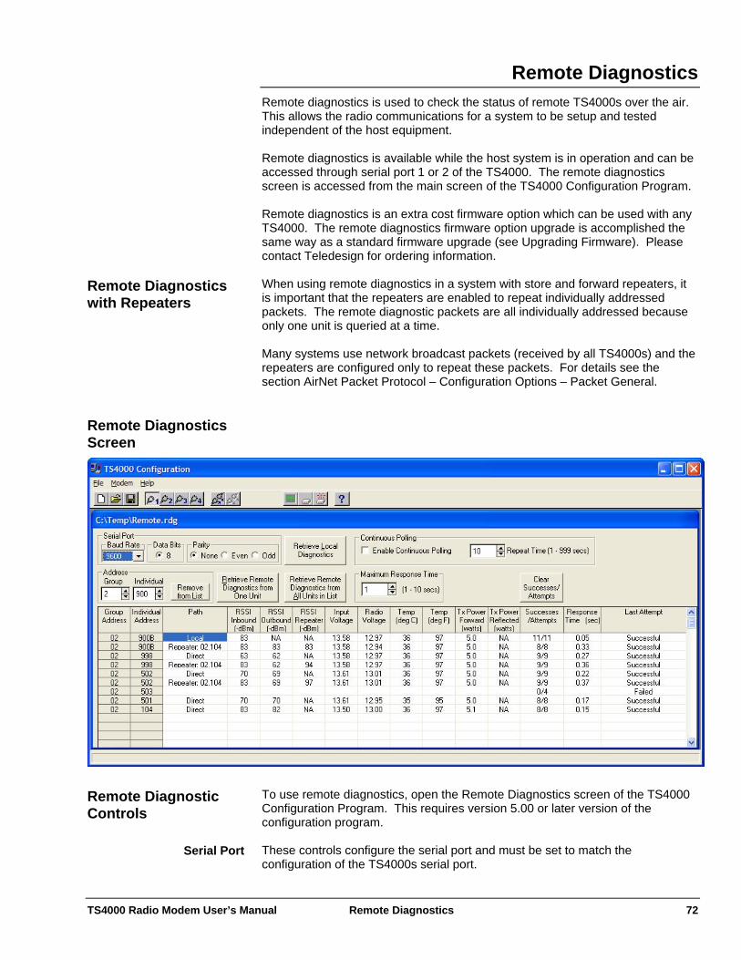
TS4000 Radio Modem User’s Manual Remote Diagnostics 72
Remote Diagnostics Remote diagnostics is used to check the status of remote TS4000s over the air. This allows the radio communications for a system to be setup and tested independent of the host equipment. Remote diagnostics is available while the host system is in operation and can be accessed through serial port 1 or 2 of the TS4000. The remote diagnostics screen is accessed from the main screen of the TS4000 Configuration Program. Remote diagnostics is an extra cost firmware option which can be used with any TS4000. The remote diagnostics firmware option upgrade is accomplished the same way as a standard firmware upgrade (see Upgrading Firmware). Please contact Teledesign for ordering information. When using remote diagnostics in a system with store and forward repeaters, it is important that the repeaters are enabled to repeat individually addressed packets. The remote diagnostic packets are all individually addressed because only one unit is queried at a time.
Remote Diagnostics with Repeaters
Many systems use network broadcast packets (received by all TS4000s) and the repeaters are configured only to repeat these packets. For details see the section AirNet Packet Protocol – Configuration Options – Packet General. Remote Diagnostics
Screen
To use remote diagnostics, open the Remote Diagnostics screen of the TS4000 Configuration Program. This requires version 5.00 or later version of the configuration program.
Remote Diagnostic Controls
These controls configure the serial port and must be set to match the configuration of the TS4000s serial port.
Serial Port

TS4000 Radio Modem User’s Manual Remote Diagnostics 73
To have the program set these automatically, connect to the modem (Modem menu – Connect to Modem), then select the desired retrieve button. The program will then disconnect from the modem and set the serial port settings to match the modem. This button is used to retrieve the diagnostics data from the TS4000 that the PC is physically connected to. This function does not require the remote diagnostics firmware upgrade option.
Retrieve Local Diagnostics
These defines the address of the TS4000 that will be queried over the air. They can also be used to choose the address to be removed from the diagnostics list.
Address
This button retrieves the remote diagnostics data from the TS4000 indicated by the address controls.
Retrieve Remote Diagnostics from One Unit
This button retrieves the remote diagnostics from all TS4000s in the diagnostics list.
Retrieve Remote Diagnostics from All Units
in List This is the maximum time that the program will wait for a diagnostics response. Maximum Response Time When this is enabled, the type of diagnostics selected (Local, Retrieve One or Retrieve All) will be polled repeatedly until it is stopped. The time between polls is set with the Repeat Time control.
Continuous Polling
This will clear the Successes/Attempts field of the diagnostics list. All other fields will be unaffected.
Clear Successes/Attempts
Field Description Group Address Group address of the modem. Individual Address Individual address of the modem.
An A or B after the address indicates that the modem is part of a redundancy switch and which modem it is.
Path This field indicates the path of the diagnostics data. Local: The data is from the modem physically connected to
the PC Direct: The data was received over the air without being
repeated by a store and forward repeater. Repeater: The data was received over the air through a
store and forward repeater. The address of the repeater is also shown. The data may come though multiple repeaters and the list will show the last five repeaters with the most recent repeater listed first. The path field can be expanded to show additional repeater addresses.
RSSI Inbound The RSSI (Receive Signal Strength Indication) value of the incoming response packet measured at the local modem. For a local path, this field indicates the RSSI of the last received packet. The units are –dBms (negative dBms) and therefore a lower value indicates a larger received signal.
Diagnostics List
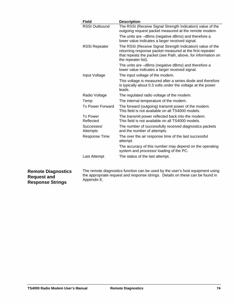
TS4000 Radio Modem User’s Manual Remote Diagnostics 74
Field Description RSSI Outbound The RSSI (Receive Signal Strength Indication) value of the
outgoing request packet measured at the remote modem. The units are –dBms (negative dBms) and therefore a lower value indicates a larger received signal.
RSSI Repeater The RSSI (Receive Signal Strength Indication) value of the returning response packet measured at the first repeater that repeats the packet (see Path, above, for information on the repeater list). The units are –dBms (negative dBms) and therefore a lower value indicates a larger received signal.
Input Voltage The input voltage of the modem. This voltage is measured after a series diode and therefore is typically about 0.3 volts under the voltage at the power leads.
Radio Voltage The regulated radio voltage of the modem. Temp The internal temperature of the modem. Tx Power Forward The forward (outgoing) transmit power of the modem.
This field is not available on all TS4000 models. Tx Power Reflected
The transmit power reflected back into the modem. This field is not available on all TS4000 models.
Successes/ Attempts
The number of successfully received diagnostics packets and the number of attempts.
Response Time The over the air response time of the last successful attempt. The accuracy of this number may depend on the operating system and processor loading of the PC.
Last Attempt The status of the last attempt. The remote diagnostics function can be used by the user’s host equipment using the appropriate request and response strings. Details on these can be found in Appendix E.
Remote Diagnostics Request and Response Strings
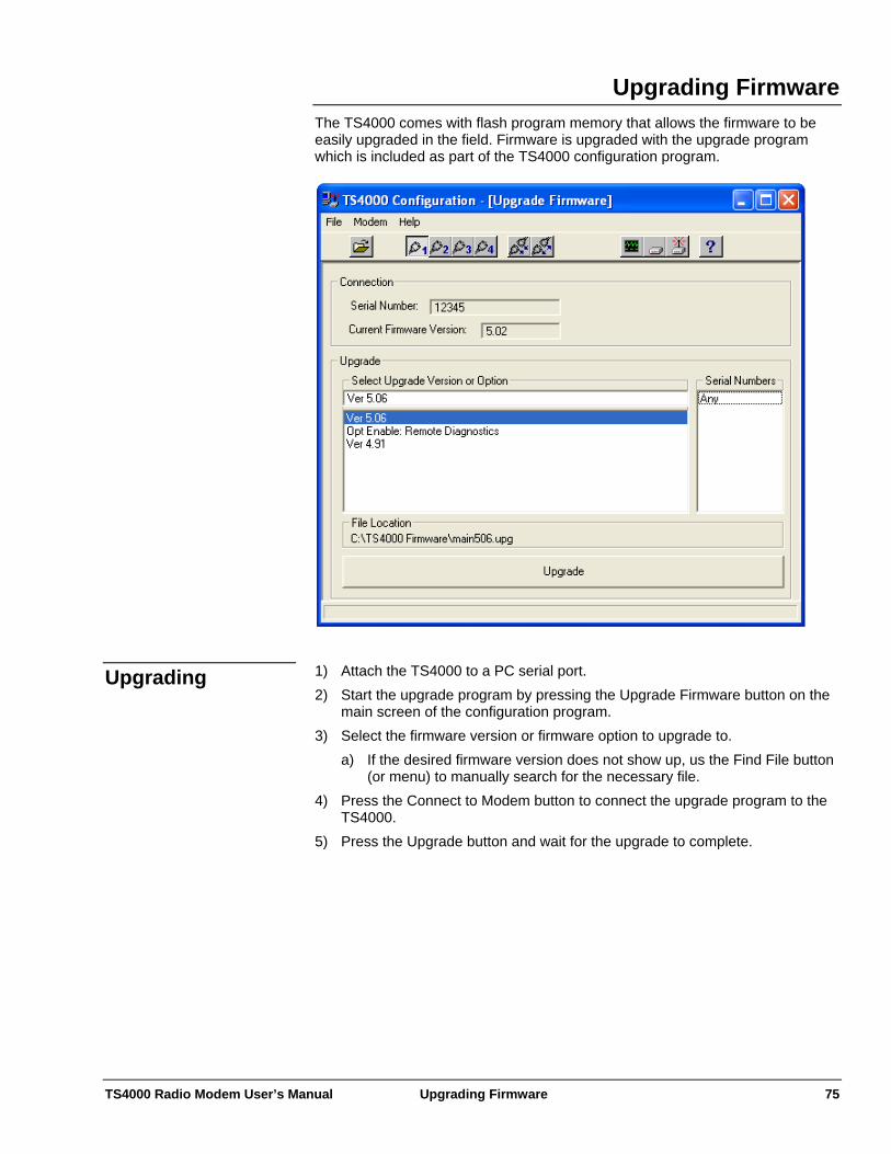
TS4000 Radio Modem User’s Manual Upgrading Firmware 75
Upgrading Firmware The TS4000 comes with flash program memory that allows the firmware to be easily upgraded in the field. Firmware is upgraded with the upgrade program which is included as part of the TS4000 configuration program.
1) Attach the TS4000 to a PC serial port. Upgrading 2) Start the upgrade program by pressing the Upgrade Firmware button on the
main screen of the configuration program. 3) Select the firmware version or firmware option to upgrade to.
a) If the desired firmware version does not show up, us the Find File button (or menu) to manually search for the necessary file.
4) Press the Connect to Modem button to connect the upgrade program to the TS4000.
5) Press the Upgrade button and wait for the upgrade to complete.
TS4000 Radio Modem User’s Manual Licensing 76
Licensing To be operated legally, radio equipment requires two types of licensing - a manufacturer’s certification that the manufacturer obtains and a users license that the user must obtain. In most cases, the user of the TS4000 is required to obtain an operating license. This is the case for most frequency ranges in most areas of the world. Licensing is done so that the government can coordinate radio users in order to minimize interference. There are a handful of unlicensed frequency in the VHF band that are available for use in the United States (see Unlicensed Operation below).
User’s License
It is the user’s responsibility to obtain the necessary licenses prior to transmitting over the air with the TS4000. The user is also responsible for proper setup, operation, and maintenance of the TS4000 so that it complies with the limits specified by the license. Changes or modifications not expressly approved by Teledesign Systems Inc. could void the user’s authority to operate this equipment. Shielded cable must be used with this equipment in order to ensure that it meets the emissions limits for which it was designed. It is the responsibility of the user to obtain and use good quality shielded interface cables with this device. Shielded interface cables are available from most retail and commercial suppliers of interface cables designed to work with personal computer peripherals. Within the different frequency bands (i.e. VHF, UHF, 900 MHz etc.) channels are licensed with a specific channel spacing (i.e. 25 kHz, 12.5kHz, etc.). The channel spacing corresponds to the difference between the center frequencies of adjacent channels. The TS4000 can be ordered with various channel spacing options.
Channel Spacing and Occupied Bandwidth
For each frequency band and channel spacing, there is a corresponding maximum occupied bandwidth. The maximum occupied bandwidth is the amount of frequency bandwidth that the user on a channel is allowed to occupy. This is typically (but not always) less than the channel spacing in order to minimize interference between users on adjacent channels. The occupied bandwidth of the TS4000 can be configured by the user (see Radio Setup). The occupied bandwidth must be set to a value less than or equal to the maximum allowed occupied bandwidth of the channels that the user is operating on. Note that the setting of occupied bandwidth limits the maximum over the air data rate that the TS4000 can operate at. The maximum over the air data rate is also dependent on the modulation type selected. For each TS4000 there is a maximum occupied bandwidth that cannot be exceeded and is dependent on the bandwidth of the specific radio module that the unit was ordered with. This maximum occupied bandwidth is configured when the unit is manufactured and cannot be changed by the end user. Within the US, the FCC indicates the maximum occupied bandwidth as part of the channel emission designator. For example, an emission designator of 16K0F1D corresponds to a 16.0 kHz occupied bandwidth. The emission designator of the licensed channel or channels shows up on the license form that is received when the FCC (or other appropriate licensing agency) grants a license.
TS4000 Radio Modem User’s Manual Licensing 77
The TS4000 is licensed under the FCC (Federal Communications Commission) Part 90 rules. The FCC regulates the operation and licensing of radio equipment in the US. To obtain a license to operate radio equipment a user must fill out the appropriate FCC forms and pay an application fee.
USA (FCC)
Many FCC licenses also require that the user obtain frequency coordination from the appropriate organization. The coordination organizations handle the up front work of qualifying applications and allocating channels. The appropriate coordination organization depends on the type of license (voice, data, paging, etc.), type of user (business, government, etc.) and the frequencies To help with the licensing process, there are companies who, for a fee, will fill out and file the paperwork necessary to obtain a license.
Licensing Service Companies
Atlas License Company 800-252-0529 www.alcds.com Professional Licensing Consultants 972-248-2400 www.fcc-licensing.com Radio Licensing Services 800-304-8821 www.radiolicensing.com FCC – Federal Communications Commission Other Contacts 888-225-5322 www.fcc.gov PCIA (Coordination agency for most business licenses) 800-759-0300 www.pcia.com Countries other than the USA have different rules for operating radio equipment. The user should work with the appropriate government agency to obtain the necessary licenses and to make sure that the TS4000 meets the licensing requirements.
International
The TS4000 radio modem can be used without a license, with some restrictions, in the United States on five specific VHF frequencies under the MURS (Multi-Use Radio System) rules of the FCC. The MURS rules allow voice or data communications for personal or business activities of the general public. The FCC rules are shown in Appendix G.
Unlicensed Operation
Note that the FCC may change, restrict, modify or amend these rules in the future. MURS allows unlicensed use on the following 5 frequencies and bandwidths: Frequencies and
Channel Bandwidth
TS4000 Radio Modem User’s Manual Licensing 78
Frequency Authorized Bandwidth 151.820 MHz 11.25 KHz 151.880 MHz 11.25 KHz 151.940 MHz 11.25 KHz 154.570 MHz 20.0 KHz 154.600 MHz 20.0 KHz This channel bandwidth (occupied bandwidth) of the TS4000 is configured on the Radio tab of the TS4000 configuration software (see Radio Setup). The MURS frequencies can be used with up to 2 watts or transmit power. For the TS4000 Radio Modem, the transmit power is set on the Radio tab in the TS4000 configuration software (see Radio Setup).
Power
The MURS rules do not currently limit the type of antenna. Antennas The highest point of any MURS antenna must be no more than 18.3 meters (60 feet) above the ground or 6.10 meters (20 feet) above the highest point of the structure on which it is mounted.
Antenna Height
The MURS rules specify that the channels must be shared with other users. The TS4000 is designed to minimize interference with other users by listening before it transmits. However, the best way to minimize interference with other channel users is to use the TS4000’s Clear Channel Scan feature. Clear Channel Scan automatically and dynamically selects the frequency with the least amount of interference (see Radio Setup).
Channel Sharing
The MURS rules do not allow the use of store and forward repeaters. A MURS radio can be used “within or over any area of the world where radio services are regulated by the FCC”.
Location
A MURS radio may not be used aboard an aircraft in flight. The TS4000 Radio Modem (Part# TS4000-05C15SBB) meets the requirements for MURS. Note that the TS4000 must be configured correctly to meet the MURS rules. The TS4000 can be ordered with a MURS compatible configuration using part# TS4000-05C15SBB-MURS.
Equipment
To sell most radio equipment, the manufacturer must obtain a certification that guarantees that their equipment meets the necessary regulations for operation. The regulations vary based on the country and frequency of operation.
Manufacturer’s Certification
USA (FCC) The TS4000 has been tested and found to comply with the limits for a Class B digital device, pursuant to Part15 of the FCC rules (Code of Federal Regulations 47CFR Part 15). Operation is subject to the condition that this device does not cause harmful interference.
Part 15
The TS4000 has been type accepted for operation by the FCC in accordance with Part 90 of the FCC rules (47CFR Part 90). See the label on the unit for the specific FCC ID and any other certification designations.
Part 90

TS4000 Radio Modem User’s Manual Licensing 79
The TS4000 has been type accepted for operation by the FCC in accordance with Part 101 of the FCC rules (47CFR Part 101). See the label on the unit for the specific FCC ID and any other certification designations.
Part 101
Industry Canada This Class B digital apparatus meets all requirements of the Canadian Interference-Causing Equipment Regulations.
ICES-003
The TS4000 has been certified for operation by Industry Canada in accordance with RSS-119 and RSS-210 of the Industry Canada rules. See the label on the unit for the specific Industry Canada certification number and any other certification designations.
RSS-119
Many countries allow radio equipment that meets the FCC rules to be operated. However, some countries have their own rules which radio manufactures must comply with. It is the user’s responsibility to ensure that the TS4000 meets the required regulations.
International
TS4000 Radio Modem User’s Manual Service and Support 80
Service and Support We at Teledesign Systems are committed to providing excellent service and support to our customers. Our goal is to make using our products as easy and painless as possible. To accomplish this Teledesign provides free technical support for all our products during all phases of sales, installation, and use. Service and technical support can be reached during our normal business hours of 8 AM to 5 PM (Pacific Standard Time) Monday through Friday. Teledesign Systems can be reached at the following phone numbers.
Contacting Teledesign
(800) 663-3674 or (800) MODEMS-4 (USA & Canada) (408) 941-1808 (408) 941-1818 (Fax) In addition we have a web site which contains our latest product information and downloads: www.teledesignsystems.com We can be reached by email at: [email protected] [email protected] We can be reached by mail at: Teledesign Systems Inc. 1729 South Main Street Milpitas, CA 95035 USA Before returning equipment to Teledesign, please call for an RMA number and shipping information. This allows us to plan for your shipment in order to provide the best possible service. When returning equipment, please include a note indicating the symptoms of the failure and any other pertinent information.
Returning Equipment
TS4000 Radio Modem User’s Manual Warranty 81
Warranty Teledesign Systems Inc. warrants this product to be free from defects in materials and workmanship for a period of two (2) years from the date of shipment. During the warranty period, Teledesign Systems Inc. will, at its option, either repair of replace products that prove to be defective.
Two Year Warranty
This warranty shall not apply to any defect, failure or damage caused by misuse, abuse, improper application, alteration, accident, disaster, negligence, use outside of the environmental specifications, improper or inadequate maintenance, or incorrect repair or servicing not performed or authorized by Teledesign Systems Inc.
Exclusions
TELEDESIGN SYSTEMS INC. SHALL IN NO EVENT HAVE OBLIGATIONS OR LIABILITIES TO BUYER OR ANY OTHER PERSON FOR LOSS OF PROFITS, LOSS OF USE OR INCIDENTAL, SPECIAL, OR CONSEQUENTIAL DAMAGES, WHETHER BASED ON CONTRACT, TORT (INCLUDING NEGLIGENCE), STRICT LIABILITY, OR ANY OTHER THEORY OR FORM OF ACTION, EVEN IF TELEDESIGN SYSTEMS INC. HAS BEEN ADVISED OF THE POSSIBILITY THEREOF, ARISING OUT OF OR IN CONNECTION WITH THE SALE, DELIVERY, USE, REPAIR, OR PERFORMANCE OF THIS PRODUCT (INCLUDING EQUIPMENT, DOCUMENTATION AND SOFTWARE). IN NO EVENT SHALL THE LIABILITY OF TELEDESIGN SYSTEMS INC. ARISING IN CONNECTION WITH ANY PRODUCT EXCEED THE ACTUAL AMOUNT PAID FOR SUCH PRODUCT.
Limitations
THIS WARRANTY IS IN LIEU OF ALL OTHER WARRANTIES, WRITTEN OR ORAL, EXPRESSED OR IMPLIED, INCLUDING IMPLIED WARRANTIES OF MERCHANTABILITY OR FITNESS FOR A PARTICULAR PURPOSE.
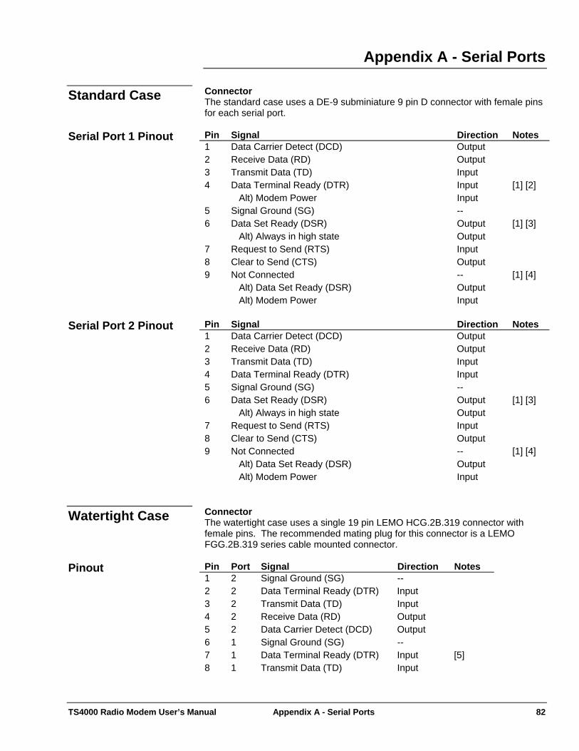
TS4000 Radio Modem User’s Manual Appendix A - Serial Ports 82
Appendix A - Serial Ports Connector Standard Case The standard case uses a DE-9 subminiature 9 pin D connector with female pins for each serial port. Pin Signal Direction Notes 1 Data Carrier Detect (DCD) Output 2 Receive Data (RD) Output 3 Transmit Data (TD) Input 4 Data Terminal Ready (DTR)
Alt) Modem Power Input Input
[1] [2]
5 Signal Ground (SG) -- 6 Data Set Ready (DSR)
Alt) Always in high state Output Output
[1] [3]
7 Request to Send (RTS) Input 8 Clear to Send (CTS) Output 9 Not Connected
Alt) Data Set Ready (DSR) Alt) Modem Power
-- Output Input
[1] [4]
Serial Port 1 Pinout
Pin Signal Direction Notes 1 Data Carrier Detect (DCD) Output 2 Receive Data (RD) Output 3 Transmit Data (TD) Input 4 Data Terminal Ready (DTR) Input 5 Signal Ground (SG) -- 6 Data Set Ready (DSR)
Alt) Always in high state Output Output
[1] [3]
7 Request to Send (RTS) Input 8 Clear to Send (CTS) Output 9 Not Connected
Alt) Data Set Ready (DSR) Alt) Modem Power
-- Output Input
[1] [4]
Serial Port 2 Pinout
Connector Watertight Case The watertight case uses a single 19 pin LEMO HCG.2B.319 connector with female pins. The recommended mating plug for this connector is a LEMO FGG.2B.319 series cable mounted connector. Pin Port Signal Direction Notes 1 2 Signal Ground (SG) -- 2 2 Data Terminal Ready (DTR) Input 3 2 Transmit Data (TD) Input 4 2 Receive Data (RD) Output 5 2 Data Carrier Detect (DCD) Output 6 1 Signal Ground (SG) -- 7 1 Data Terminal Ready (DTR) Input [5] 8 1 Transmit Data (TD) Input
Pinout

TS4000 Radio Modem User’s Manual Appendix A - Serial Ports 83
Pin Port Signal Direction Notes 9 1 Receive Data (RD) Output 10 1 Data Carrier Detect (DCD) Output 11 -- Ground (Power) -- 12 -- Modem Power Input 13 2 Clear To Send (CTS) Output 14 2 Request To Send (RTS) Input 15 2 Data Set Ready (DSR)
Alt) Always in high state Output Output
[1] [3]
16 1 Not Connected Alt) Data Set Ready (DSR)
-- Output
[1] [4] [5]
17 1 Request To Send (RTS) Input 18 1 Data Set Ready (DSR)
Alt) Always in high state Output Output
[1] [3]
19 1 Clear To Send (CTS) Output
Data Port 2
19
1211
13
6 785
164 15 917
10183 14
21
Power (+)
Ground (-)
Ground
Ground
DTR-2
RTS-1 RD-1
DCD-1DSR-1
CTS-2
RD-2
TD-2 RTS-2
DSR-2
RI-1
TD-1
CTS-1
DCD-2
DTR-1
TS4000 LEMO Connector(viewed from front of TS4000)
Data Port 1
ModemPower
[1] These pins have multiple internal signals that they can be connected to. The
connection options are selected with internal jumper plugs (see Appendix F - Internal Jumper Block).
Notes
[2] This pin is normally setup as the serial port Data Terminal Ready (DTR) line,
which is an input for DCEs (input to the TS4000). As an alternative, this pin can be setup to feed DC power into the TS4000.
Caution: The use of the DTR pin for a DC power input connection is non-standard. Therefore the TS4000 serial port must not be connected to a standard serial device that drives the DTR pin (i.e. a PC). This could result in the power supply voltage of the TS4000 being shorted to the DTR output of the host serial port, which could damage to the host device. Therefore, when connecting the TS4000 to a PC for configuration, make sure that the cable does not have a DTR (pin 4) connection.
[3] This pin is normally setup as the serial port Data Set Ready (DSR) line,
which is an output for DCEs (output of the TS4000). As an alternative, this
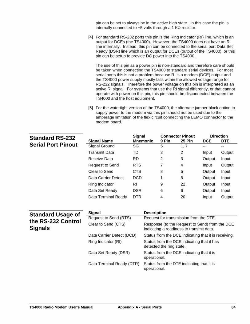
TS4000 Radio Modem User’s Manual Appendix A - Serial Ports 84
pin can be set to always be in the active high state. In this case the pin is internally connected to +5 volts through a 1 KΩ resistor.
[4] For standard RS-232 ports this pin is the Ring Indicator (RI) line, which is an
output for DCEs (the TS4000). However, the TS4000 does not have an RI line internally. Instead, this pin can be connected to the serial port Data Set Ready (DSR) line which is an output for DCEs (output of the TS4000), or this pin can be setup to provide DC power into the TS4000.
The use of this pin as a power pin is non-standard and therefore care should be taken when connecting the TS4000 to standard serial devices. For most serial ports this is not a problem because RI is a modem (DCE) output and the TS4000 power supply mostly falls within the allowed voltage range for RS-232 signals. Therefore the power voltage on this pin is interpreted as an active RI signal. For systems that use the RI signal differently, or that cannot operate with power on this pin, this pin should be disconnected between the TS4000 and the host equipment.
[5] For the watertight version of the TS4000, the alternate jumper block option to supply power to the modem via this pin should not be used due to the amperage limitation of the flex circuit connecting the LEMO connector to the modem board.
Signal Connector Pinout Direction Signal Name Mnemonic 9 Pin 25 Pin DCE DTE Signal Ground SG 5 1, 7 -- -- Transmit Data TD 3 2 Input Output Receive Data RD 2 3 Output Input Request to Send RTS 7 4 Input Output Clear to Send CTS 8 5 Output Input Data Carrier Detect DCD 1 8 Output Input Ring Indicator RI 9 22 Output Input Data Set Ready DSR 6 6 Output Input Data Terminal Ready DTR 4 20 Input Output
Standard RS-232 Serial Port Pinout
Signal Description Request to Send (RTS) Request for transmission from the DTE. Clear to Send (CTS) Response (to the Request to Send) from the DCE
indicating a readiness to transmit data. Data Carrier Detect (DCD) Status from the DCE indicating that it is receiving. Ring Indicator (RI) Status from the DCE indicating that it has
detected the ring state. Data Set Ready (DSR) Status from the DCE indicating that it is
operational. Data Terminal Ready (DTR) Status from the DTE indicating that it is
operational.
Standard Usage of the RS-232 Control Signals
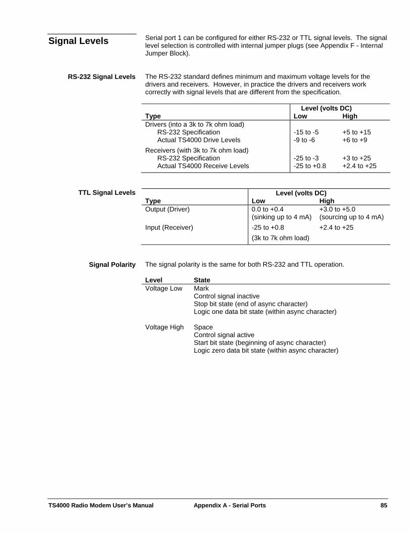
TS4000 Radio Modem User’s Manual Appendix A - Serial Ports 85
Serial port 1 can be configured for either RS-232 or TTL signal levels. The signal level selection is controlled with internal jumper plugs (see Appendix F - Internal Jumper Block).
Signal Levels
The RS-232 standard defines minimum and maximum voltage levels for the drivers and receivers. However, in practice the drivers and receivers work correctly with signal levels that are different from the specification.
RS-232 Signal Levels
Level (volts DC) Type Low High Drivers (into a 3k to 7k ohm load)
RS-232 Specification Actual TS4000 Drive Levels
-15 to -5 -9 to -6
+5 to +15 +6 to +9
Receivers (with 3k to 7k ohm load) RS-232 Specification Actual TS4000 Receive Levels
-25 to -3 -25 to +0.8
+3 to +25 +2.4 to +25
TTL Signal Levels Level (volts DC) Type Low High Output (Driver) 0.0 to +0.4
(sinking up to 4 mA) +3.0 to +5.0 (sourcing up to 4 mA)
Input (Receiver) -25 to +0.8 +2.4 to +25 (3k to 7k ohm load) The signal polarity is the same for both RS-232 and TTL operation. Signal Polarity Level State Voltage Low Mark
Control signal inactive Stop bit state (end of async character) Logic one data bit state (within async character)
Voltage High Space Control signal active Start bit state (beginning of async character) Logic zero data bit state (within async character)
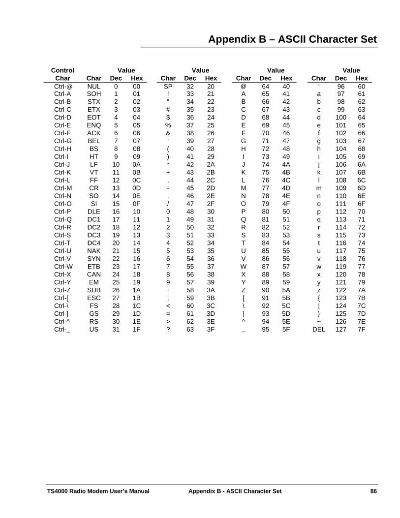
TS4000 Radio Modem User’s Manual Appendix B - ASCII Character Set 86
Appendix B – ASCII Character Set
Control Value Char Char Dec Hex Ctrl-@ NUL 0 00 Ctrl-A SOH 1 01 Ctrl-B STX 2 02 Ctrl-C ETX 3 03 Ctrl-D EOT 4 04 Ctrl-E ENQ 5 05 Ctrl-F ACK 6 06 Ctrl-G BEL 7 07 Ctrl-H BS 8 08 Ctrl-I HT 9 09 Ctrl-J LF 10 0A Ctrl-K VT 11 0B Ctrl-L FF 12 0C Ctrl-M CR 13 0D Ctrl-N SO 14 0E Ctrl-O SI 15 0F Ctrl-P DLE 16 10 Ctrl-Q DC1 17 11 Ctrl-R DC2 18 12 Ctrl-S DC3 19 13 Ctrl-T DC4 20 14 Ctrl-U NAK 21 15 Ctrl-V SYN 22 16 Ctrl-W ETB 23 17 Ctrl-X CAN 24 18 Ctrl-Y EM 25 19 Ctrl-Z SUB 26 1A Ctrl-[ ESC 27 1B Ctrl-\ FS 28 1C Ctrl-] GS 29 1D Ctrl-^ RS 30 1E Ctrl-_ US 31 1F
Value Char Dec Hex SP 32 20! 33 21 “ 34 22 # 35 23 $ 36 24 % 37 25 & 38 26 ‘ 39 27 ( 40 28 ) 41 29 * 42 2A + 43 2B , 44 2C - 45 2D . 46 2E / 47 2F 0 48 30 1 49 31 2 50 32 3 51 33 4 52 34 5 53 35 6 54 36 7 55 37 8 56 38 9 57 39 : 58 3A ; 59 3B < 60 3C = 61 3D > 62 3E ? 63 3F
Value Char Dec Hex
@ 64 40 A 65 41 B 66 42 C 67 43 D 68 44 E 69 45 F 70 46 G 71 47 H 72 48 I 73 49 J 74 4A K 75 4B L 76 4C M 77 4D N 78 4E O 79 4F P 80 50 Q 81 51 R 82 52 S 83 53 T 84 54 U 85 55 V 86 56 W 87 57 X 88 58 Y 89 59 Z 90 5A [ 91 5B \ 92 5C ] 93 5D ^ 94 5E _ 95 5F
Value Char Dec Hex
‘ 96 60a 97 61 b 98 62 c 99 63 d 100 64 e 101 65 f 102 66 g 103 67 h 104 68 i 105 69 j 106 6A k 107 6B l 108 6C
m 109 6D n 110 6E o 111 6F p 112 70 q 113 71 r 114 72 s 115 73 t 116 74 u 117 75 v 118 76 w 119 77 x 120 78 y 121 79 z 122 7A { 123 7B | 124 7C } 125 7D ~ 126 7E
DEL 127 7F
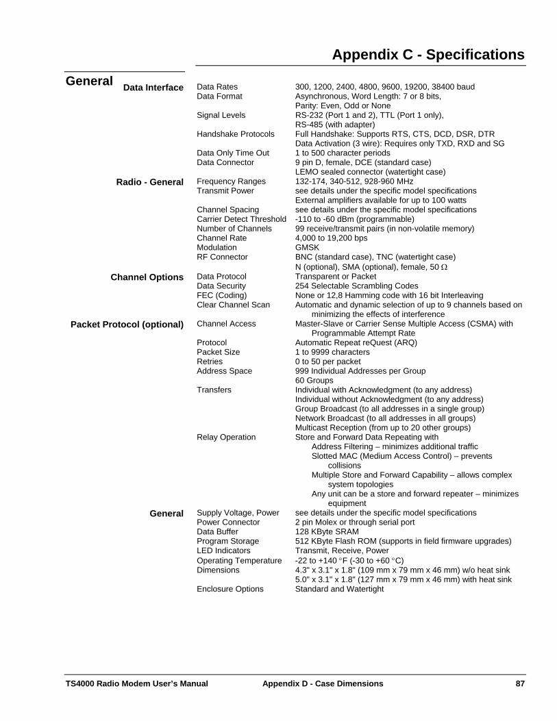
TS4000 Radio Modem User’s Manual Appendix D - Case Dimensions 87
Appendix C - Specifications General Data Rates 300, 1200, 2400, 4800, 9600, 19200, 38400 baud Data Interface Data Format Asynchronous, Word Length: 7 or 8 bits, Parity: Even, Odd or None Signal Levels RS-232 (Port 1 and 2), TTL (Port 1 only), RS-485 (with adapter) Handshake Protocols Full Handshake: Supports RTS, CTS, DCD, DSR, DTR Data Activation (3 wire): Requires only TXD, RXD and SG Data Only Time Out 1 to 500 character periods Data Connector 9 pin D, female, DCE (standard case) LEMO sealed connector (watertight case) Frequency Ranges 132-174, 340-512, 928-960 MHz Radio - General Transmit Power see details under the specific model specifications External amplifiers available for up to 100 watts Channel Spacing see details under the specific model specifications Carrier Detect Threshold -110 to -60 dBm (programmable) Number of Channels 99 receive/transmit pairs (in non-volatile memory) Channel Rate 4,000 to 19,200 bps Modulation GMSK RF Connector BNC (standard case), TNC (watertight case) N (optional), SMA (optional), female, 50 Ω Data Protocol Transparent or Packet Channel Options Data Security 254 Selectable Scrambling Codes FEC (Coding) None or 12,8 Hamming code with 16 bit Interleaving Clear Channel Scan Automatic and dynamic selection of up to 9 channels based on
minimizing the effects of interference Channel Access Master-Slave or Carrier Sense Multiple Access (CSMA) with
Programmable Attempt Rate Packet Protocol (optional)
Protocol Automatic Repeat reQuest (ARQ) Packet Size 1 to 9999 characters Retries 0 to 50 per packet Address Space 999 Individual Addresses per Group 60 Groups Transfers Individual with Acknowledgment (to any address) Individual without Acknowledgment (to any address) Group Broadcast (to all addresses in a single group) Network Broadcast (to all addresses in all groups) Multicast Reception (from up to 20 other groups) Relay Operation Store and Forward Data Repeating with
Address Filtering – minimizes additional traffic Slotted MAC (Medium Access Control) – prevents
collisions Multiple Store and Forward Capability – allows complex
system topologies Any unit can be a store and forward repeater – minimizes
equipment Supply Voltage, Power see details under the specific model specifications General Power Connector 2 pin Molex or through serial port Data Buffer 128 KByte SRAM Program Storage 512 KByte Flash ROM (supports in field firmware upgrades) LED Indicators Transmit, Receive, Power Operating Temperature -22 to +140 °F (-30 to +60 °C) Dimensions 4.3" x 3.1" x 1.8" (109 mm x 79 mm x 46 mm) w/o heat sink 5.0" x 3.1" x 1.8" (127 mm x 79 mm x 46 mm) with heat sink Enclosure Options Standard and Watertight
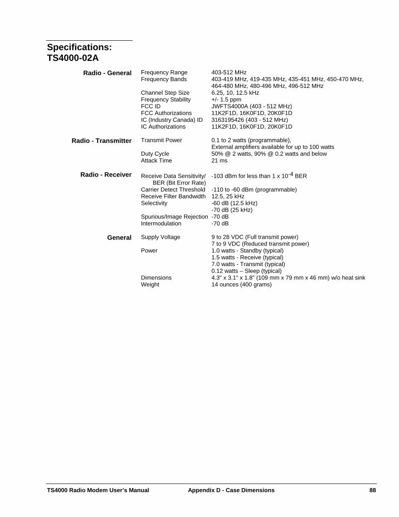
TS4000 Radio Modem User’s Manual Appendix D - Case Dimensions 88
Specifications:
TS4000-02A Frequency Range 403-512 MHz Radio - General Frequency Bands 403-419 MHz, 419-435 MHz, 435-451 MHz, 450-470 MHz,
464-480 MHz, 480-496 MHz, 496-512 MHz Channel Step Size 6.25, 10, 12.5 kHz Frequency Stability +/- 1.5 ppm FCC ID JWFTS4000A (403 - 512 MHz) FCC Authorizations 11K2F1D, 16K0F1D, 20K0F1D IC (Industry Canada) ID 3163195426 (403 - 512 MHz) IC Authorizations 11K2F1D, 16K0F1D, 20K0F1D Transmit Power 0.1 to 2 watts (programmable), Radio - Transmitter External amplifiers available for up to 100 watts Duty Cycle 50% @ 2 watts, 90% @ 0.2 watts and below Attack Time 21 ms Receive Data Sensitivity/ -103 dBm for less than 1 x 10⁻⁴ BER Radio - Receiver BER (Bit Error Rate) Carrier Detect Threshold -110 to -60 dBm (programmable) Receive Filter Bandwidth 12.5, 25 kHz Selectivity -60 dB (12.5 kHz) -70 dB (25 kHz) Spurious/Image Rejection -70 dB Intermodulation -70 dB Supply Voltage 9 to 28 VDC (Full transmit power) General 7 to 9 VDC (Reduced transmit power) Power 1.0 watts - Standby (typical) 1.5 watts - Receive (typical) 7.0 watts - Transmit (typical) 0.12 watts – Sleep (typical) Dimensions 4.3" x 3.1" x 1.8" (109 mm x 79 mm x 46 mm) w/o heat sink Weight 14 ounces (400 grams)

TS4000 Radio Modem User’s Manual Appendix D - Case Dimensions 89
Specifications:
TS4000-05B Frequency Range 380-512 MHz Radio - General Frequency Bands 380-403 MHz, 403-419 MHz, 419-435 MHz, 435-451 MHz,
450-470 MHz, 464-480 MHz, 480-496 MHz, 496-512 MHz Channel Step Size 6.25, 10, 12.5 KHz Frequency Stability +/- 1.5 ppm FCC ID JWFTS4000B (403 -512 MHz) FCC Authorizations 11K2F1D, 16K0F1D, 20K0F1D IC (Industry Canada) ID 3163195542A (403 - 512 MHz) IC Authorizations 11K2F1D, 16K0F1D, 20K0F1D Transmit Power 0.5 to 5 watts (programmable), Radio - Transmitter External amplifiers available for up to 100 watts Duty Cycle 50% @ 5 watts, 90% @ 2 watts and below Attack Time 21 ms Receive Data Sensitivity/ -103 dBm for less than 1 x 10⁻⁴ BER Radio - Receiver BER (Bit Error Rate) Carrier Detect Threshold -110 to -60 dBm (programmable) Receive Filter Bandwidth 12.5, 25 kHz Selectivity -60 dB (12.5 kHz) -70 dB (25 kHz) Spurious/Image Rejection -70 dB Intermodulation -70 dB Supply Voltage 14 to 28 VDC (Full transmit power) General 11 to 14 VDC (Reduced transmit power) Power 1.0 watts - Standby (typical) 1.5 watts - Receive (typical) 27 watts - Transmit (typical) 0.12 watts – Sleep (typical) Dimensions 6.5" x 3.1" x 1.8" (165 mm x 79 mm x 46 mm) with heat sink Weight 20 ounces (560 grams)
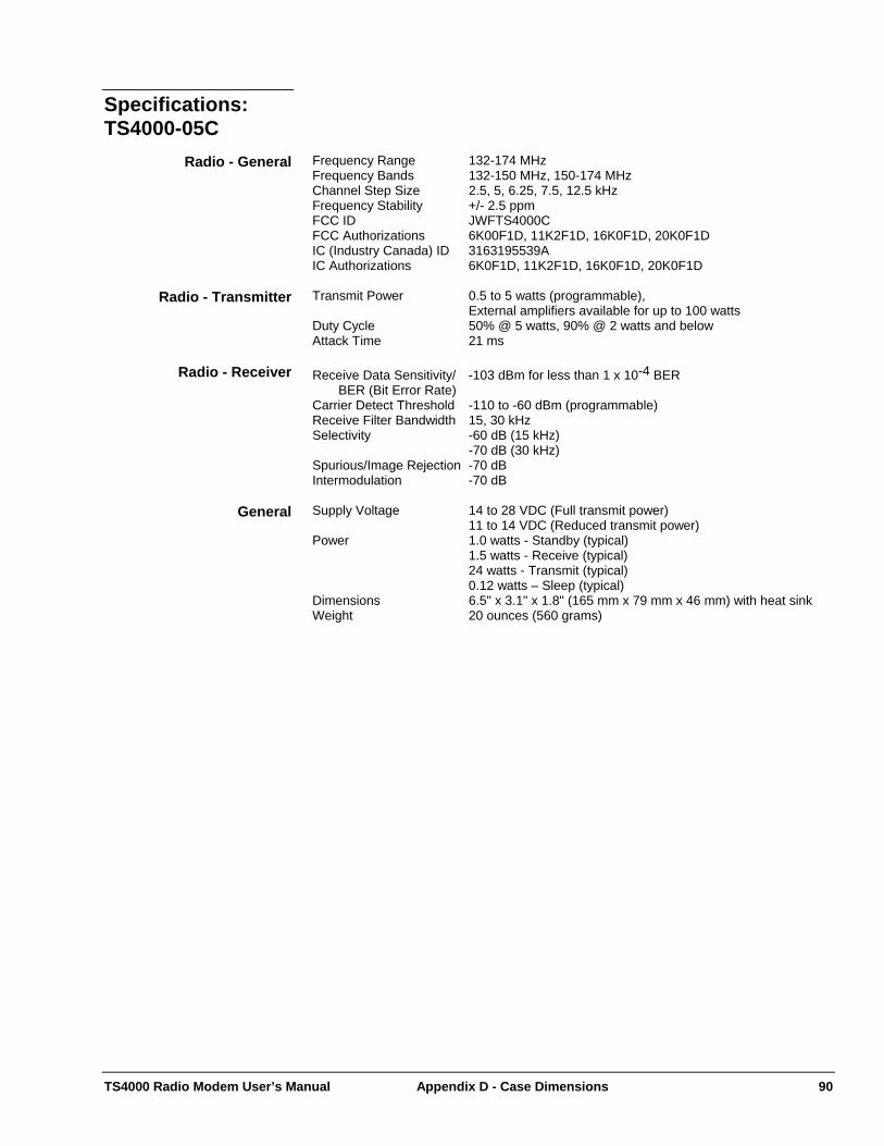
TS4000 Radio Modem User’s Manual Appendix D - Case Dimensions 90
Specifications:
TS4000-05C Frequency Range 132-174 MHz Radio - General Frequency Bands 132-150 MHz, 150-174 MHz Channel Step Size 2.5, 5, 6.25, 7.5, 12.5 kHz Frequency Stability +/- 2.5 ppm FCC ID JWFTS4000C FCC Authorizations 6K00F1D, 11K2F1D, 16K0F1D, 20K0F1D IC (Industry Canada) ID 3163195539A IC Authorizations 6K0F1D, 11K2F1D, 16K0F1D, 20K0F1D Transmit Power 0.5 to 5 watts (programmable), Radio - Transmitter External amplifiers available for up to 100 watts Duty Cycle 50% @ 5 watts, 90% @ 2 watts and below Attack Time 21 ms Receive Data Sensitivity/ -103 dBm for less than 1 x 10⁻⁴ BER Radio - Receiver BER (Bit Error Rate) Carrier Detect Threshold -110 to -60 dBm (programmable) Receive Filter Bandwidth 15, 30 kHz Selectivity -60 dB (15 kHz) -70 dB (30 kHz) Spurious/Image Rejection -70 dB Intermodulation -70 dB Supply Voltage 14 to 28 VDC (Full transmit power) General 11 to 14 VDC (Reduced transmit power) Power 1.0 watts - Standby (typical) 1.5 watts - Receive (typical) 24 watts - Transmit (typical) 0.12 watts – Sleep (typical) Dimensions 6.5" x 3.1" x 1.8" (165 mm x 79 mm x 46 mm) with heat sink Weight 20 ounces (560 grams)
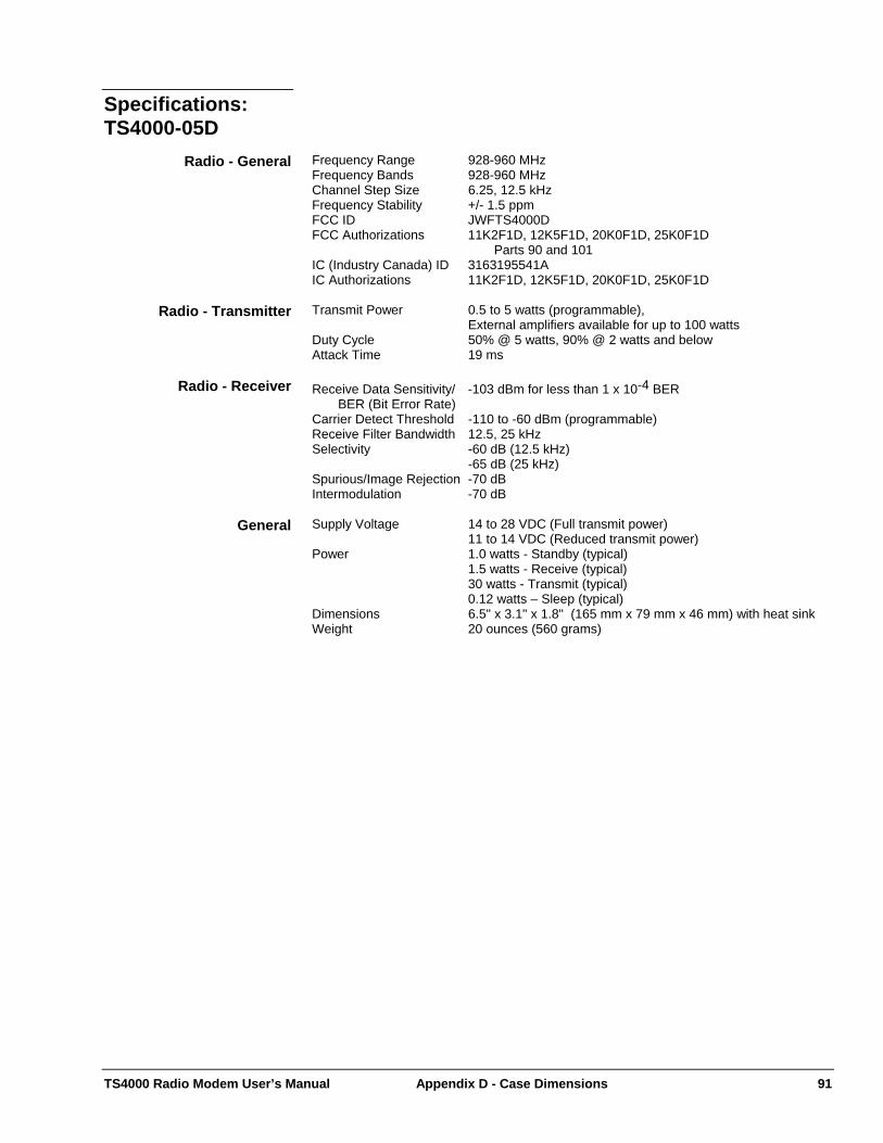
TS4000 Radio Modem User’s Manual Appendix D - Case Dimensions 91
Specifications:
TS4000-05D Frequency Range 928-960 MHz Radio - General Frequency Bands 928-960 MHz Channel Step Size 6.25, 12.5 kHz Frequency Stability +/- 1.5 ppm FCC ID JWFTS4000D FCC Authorizations 11K2F1D, 12K5F1D, 20K0F1D, 25K0F1D Parts 90 and 101 IC (Industry Canada) ID 3163195541A IC Authorizations 11K2F1D, 12K5F1D, 20K0F1D, 25K0F1D Transmit Power 0.5 to 5 watts (programmable), Radio - Transmitter External amplifiers available for up to 100 watts Duty Cycle 50% @ 5 watts, 90% @ 2 watts and below Attack Time 19 ms Receive Data Sensitivity/ -103 dBm for less than 1 x 10⁻⁴ BER Radio - Receiver BER (Bit Error Rate) Carrier Detect Threshold -110 to -60 dBm (programmable) Receive Filter Bandwidth 12.5, 25 kHz Selectivity -60 dB (12.5 kHz) -65 dB (25 kHz) Spurious/Image Rejection -70 dB Intermodulation -70 dB Supply Voltage 14 to 28 VDC (Full transmit power) General 11 to 14 VDC (Reduced transmit power) Power 1.0 watts - Standby (typical) 1.5 watts - Receive (typical) 30 watts - Transmit (typical) 0.12 watts – Sleep (typical) Dimensions 6.5" x 3.1" x 1.8" (165 mm x 79 mm x 46 mm) with heat sink Weight 20 ounces (560 grams)
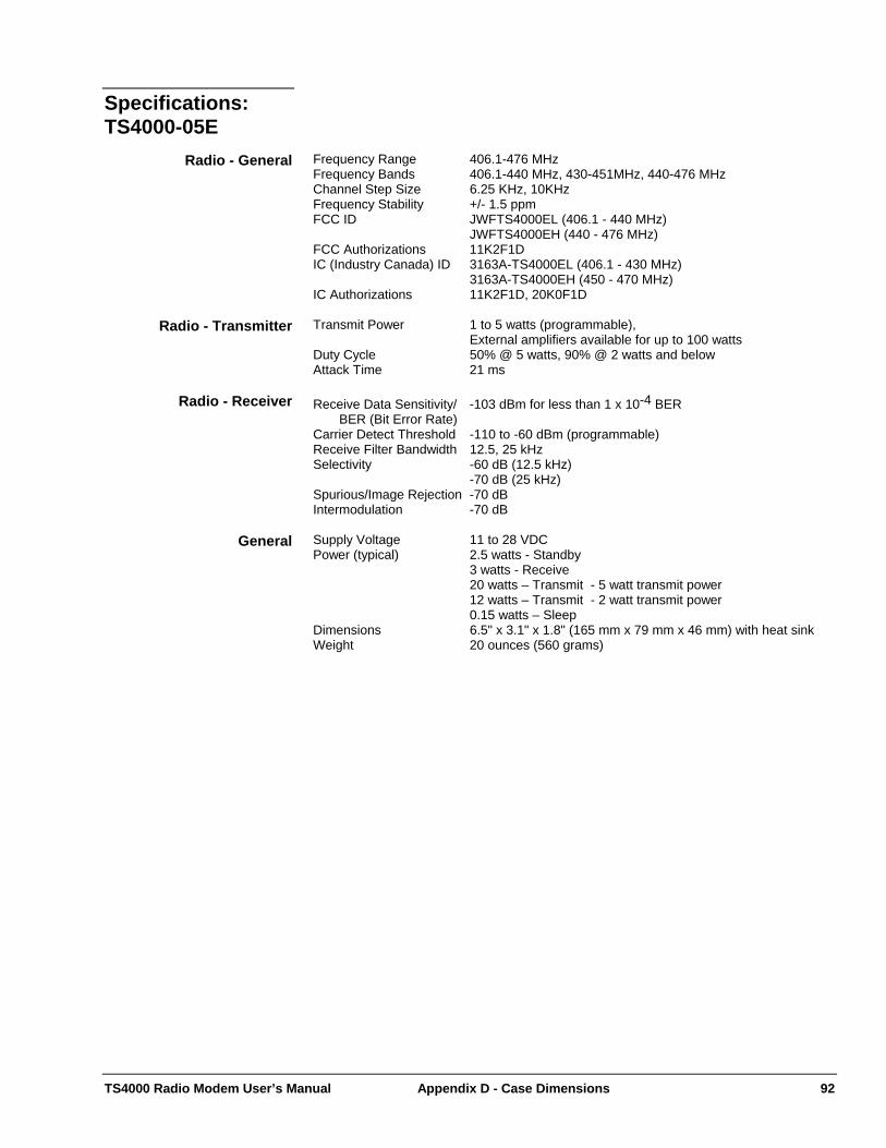
TS4000 Radio Modem User’s Manual Appendix D - Case Dimensions 92
Specifications:
TS4000-05E Frequency Range 406.1-476 MHz Radio - General Frequency Bands 406.1-440 MHz, 430-451MHz, 440-476 MHz Channel Step Size 6.25 KHz, 10KHz Frequency Stability +/- 1.5 ppm FCC ID JWFTS4000EL (406.1 - 440 MHz) JWFTS4000EH (440 - 476 MHz) FCC Authorizations 11K2F1D IC (Industry Canada) ID 3163A-TS4000EL (406.1 - 430 MHz) 3163A-TS4000EH (450 - 470 MHz) IC Authorizations 11K2F1D, 20K0F1D Transmit Power 1 to 5 watts (programmable), Radio - Transmitter External amplifiers available for up to 100 watts Duty Cycle 50% @ 5 watts, 90% @ 2 watts and below Attack Time 21 ms Receive Data Sensitivity/ -103 dBm for less than 1 x 10⁻⁴ BER Radio - Receiver BER (Bit Error Rate) Carrier Detect Threshold -110 to -60 dBm (programmable) Receive Filter Bandwidth 12.5, 25 kHz Selectivity -60 dB (12.5 kHz) -70 dB (25 kHz) Spurious/Image Rejection -70 dB Intermodulation -70 dB Supply Voltage 11 to 28 VDC General Power (typical) 2.5 watts - Standby 3 watts - Receive 20 watts – Transmit - 5 watt transmit power 12 watts – Transmit - 2 watt transmit power 0.15 watts – Sleep Dimensions 6.5" x 3.1" x 1.8" (165 mm x 79 mm x 46 mm) with heat sink Weight 20 ounces (560 grams)

TS4000 Radio Modem User’s Manual Appendix D - Case Dimensions 93
Specifications:
TS4000-05F Frequency Range 340-400MHz Radio - General Frequency Bands 340-360 MHz, 360-380 MHz, 380-400 MHz Channel Step Size 6.25 KHz Frequency Stability +/- 1.5 ppm Certification These bands cannot be certified by the FCC and IC
and therefore are not available for commercial (non-government) sales in the United States and Canada.
Transmit Power 0.5 to 5 watts (programmable), Radio - Transmitter External amplifiers available for up to 100 watts Duty Cycle 50% @ 5 watts, 90% @ 2 watts and below Attack Time 21 ms Receive Data Sensitivity/ -103 dBm for less than 1 x 10⁻⁴ BER Radio - Receiver BER (Bit Error Rate) Carrier Detect Threshold -110 to -60 dBm (programmable) Receive Filter Bandwidth 12.5, 25 kHz Selectivity -60 dB (12.5 kHz) -70 dB (25 kHz) Spurious/Image Rejection -70 dB Intermodulation -67 dB Supply Voltage 9 to 28 VDC General Power (typical) 1.5 watts - Standby 2 watts - Receive 22 watts - Transmit 0.15 watts – Sleep Dimensions 6.5" x 3.1" x 1.8" (165 mm x 79 mm x 46 mm) with heat sink Weight 20 ounces (560 grams)
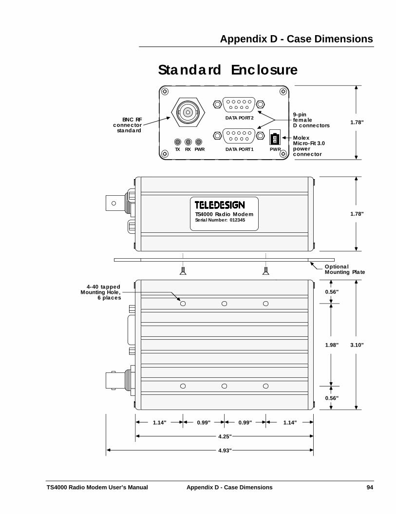
TS4000 Radio Modem User’s Manual Appendix D - Case Dimensions 94
Appendix D - Case Dimensions
3.10"
0.56"
1.98"
0.56"
Standard Enclosure
4.25"
4.93"
1.14"0.99" 0.99"
TS4000 Radio ModemSerial Number: 012345
1.78"
OptionalMounting Plate
1.78"
4-40 tappedMounting Hole,
6 places
1.14"
DATA PORT 1TX RX PWR PWR
DATA PORT 2BNC RFconnector
standard
9-pinfemaleD connectors
MolexMicro-Fit 3.0power connector
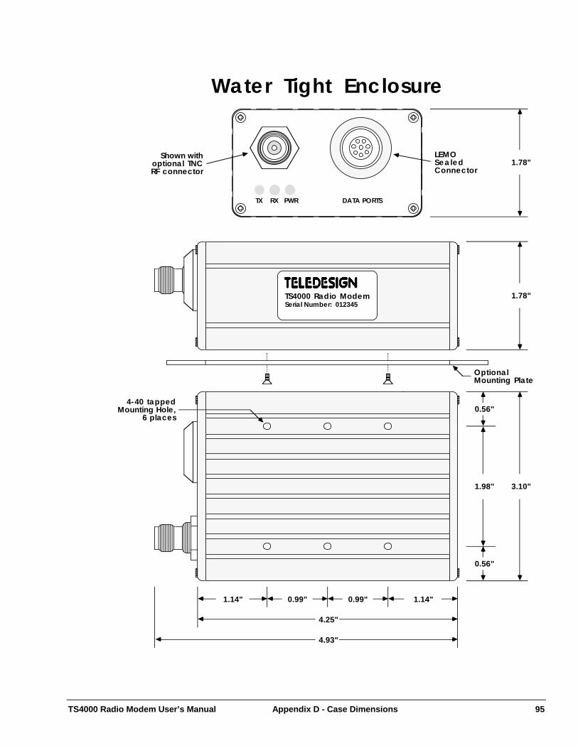
TS4000 Radio Modem User’s Manual Appendix D - Case Dimensions 95
3.10"
0.56"
1.98"
0.56"
Water Tight Enclosure
4.25"
4.93"
1.14"0.99" 0.99"
TS4000 Radio ModemSerial Number: 012345
TX RX PWR
1.78"
OptionalMounting Plate
1.78"LEMOSealedConnector
4-40 tappedMounting Hole,
6 places
DATA PORTS
Shown withoptional TNCRF connector
1.14"
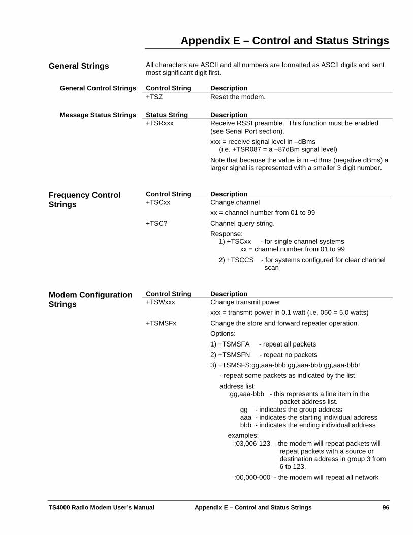
TS4000 Radio Modem User’s Manual Appendix E – Control and Status Strings 96
Appendix E – Control and Status Strings All characters are ASCII and all numbers are formatted as ASCII digits and sent most significant digit first.
General Strings Control String Description General Control Strings +TSZ Reset the modem. Status String Description Message Status Strings +TSRxxx Receive RSSI preamble. This function must be enabled
(see Serial Port section). xxx = receive signal level in –dBms
(i.e. +TSR087 = a –87dBm signal level) Note that because the value is in –dBms (negative dBms) a larger signal is represented with a smaller 3 digit number.
Control String Description Frequency Control
Strings +TSCxx Change channel xx = channel number from 01 to 99
+TSC? Channel query string. Response:
1) +TSCxx - for single channel systems xx = channel number from 01 to 99
2) +TSCCS - for systems configured for clear channel scan
Control String Description Modem Configuration
Strings +TSWxxx Change transmit power xxx = transmit power in 0.1 watt (i.e. 050 = 5.0 watts)
+TSMSFx Change the store and forward repeater operation. Options: 1) +TSMSFA - repeat all packets 2) +TSMSFN - repeat no packets 3) +TSMSFS:gg,aaa-bbb:gg,aaa-bbb:gg,aaa-bbb!
- repeat some packets as indicated by the list. address list:
:gg,aaa-bbb - this represents a line item in the packet address list.
gg - indicates the group address aaa - indicates the starting individual address bbb - indicates the ending individual address
examples: :03,006-123 - the modem will repeat packets will
repeat packets with a source or destination address in group 3 from 6 to 123.
:00,000-000 - the modem will repeat all network
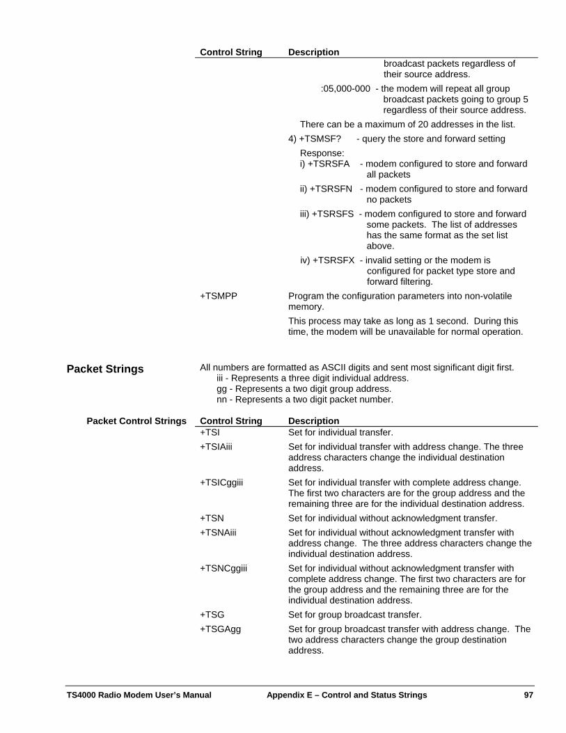
TS4000 Radio Modem User’s Manual Appendix E – Control and Status Strings 97
Control String Description broadcast packets regardless of their source address.
:05,000-000 - the modem will repeat all group broadcast packets going to group 5 regardless of their source address.
There can be a maximum of 20 addresses in the list. 4) +TSMSF? - query the store and forward setting
Response: i) +TSRSFA - modem configured to store and forward
all packets ii) +TSRSFN - modem configured to store and forward
no packets iii) +TSRSFS - modem configured to store and forward
some packets. The list of addresses has the same format as the set list above.
iv) +TSRSFX - invalid setting or the modem is configured for packet type store and forward filtering.
+TSMPP Program the configuration parameters into non-volatile memory. This process may take as long as 1 second. During this time, the modem will be unavailable for normal operation.
All numbers are formatted as ASCII digits and sent most significant digit first. Packet Strings iii - Represents a three digit individual address. gg - Represents a two digit group address. nn - Represents a two digit packet number. Control String Description Packet Control Strings +TSI Set for individual transfer. +TSIAiii Set for individual transfer with address change. The three
address characters change the individual destination address.
+TSICggiii Set for individual transfer with complete address change. The first two characters are for the group address and the remaining three are for the individual destination address.
+TSN Set for individual without acknowledgment transfer. +TSNAiii Set for individual without acknowledgment transfer with
address change. The three address characters change the individual destination address.
+TSNCggiii Set for individual without acknowledgment transfer with complete address change. The first two characters are for the group address and the remaining three are for the individual destination address.
+TSG Set for group broadcast transfer. +TSGAgg Set for group broadcast transfer with address change. The
two address characters change the group destination address.
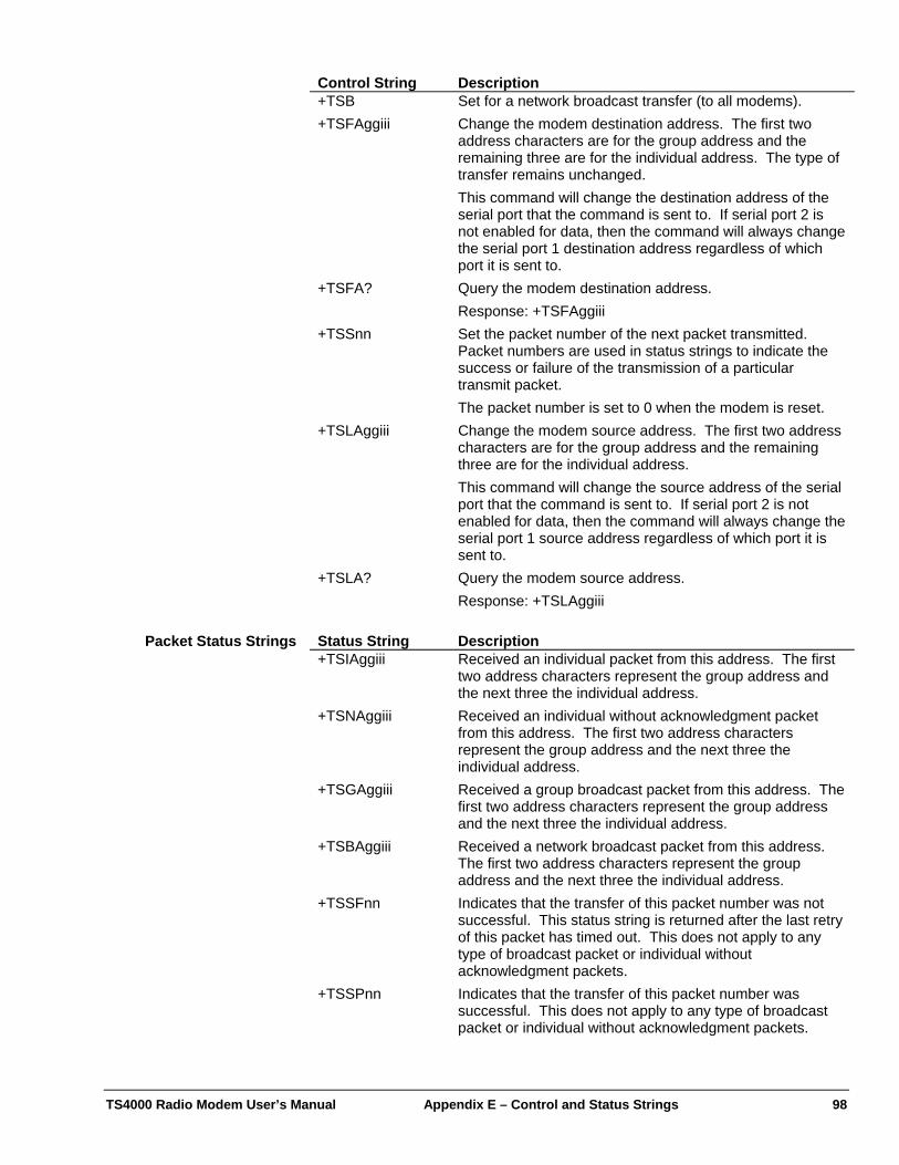
TS4000 Radio Modem User’s Manual Appendix E – Control and Status Strings 98
Control String Description +TSB Set for a network broadcast transfer (to all modems). +TSFAggiii Change the modem destination address. The first two
address characters are for the group address and the remaining three are for the individual address. The type of transfer remains unchanged. This command will change the destination address of the serial port that the command is sent to. If serial port 2 is not enabled for data, then the command will always change the serial port 1 destination address regardless of which port it is sent to.
+TSFA? Query the modem destination address. Response: +TSFAggiii
+TSSnn Set the packet number of the next packet transmitted. Packet numbers are used in status strings to indicate the success or failure of the transmission of a particular transmit packet. The packet number is set to 0 when the modem is reset.
+TSLAggiii Change the modem source address. The first two address characters are for the group address and the remaining three are for the individual address. This command will change the source address of the serial port that the command is sent to. If serial port 2 is not enabled for data, then the command will always change the serial port 1 source address regardless of which port it is sent to.
+TSLA? Query the modem source address. Response: +TSLAggiii
Status String Description Packet Status Strings +TSIAggiii Received an individual packet from this address. The first
two address characters represent the group address and the next three the individual address.
+TSNAggiii Received an individual without acknowledgment packet from this address. The first two address characters represent the group address and the next three the individual address.
+TSGAggiii Received a group broadcast packet from this address. The first two address characters represent the group address and the next three the individual address.
+TSBAggiii Received a network broadcast packet from this address. The first two address characters represent the group address and the next three the individual address.
+TSSFnn Indicates that the transfer of this packet number was not successful. This status string is returned after the last retry of this packet has timed out. This does not apply to any type of broadcast packet or individual without acknowledgment packets.
+TSSPnn Indicates that the transfer of this packet number was successful. This does not apply to any type of broadcast packet or individual without acknowledgment packets.
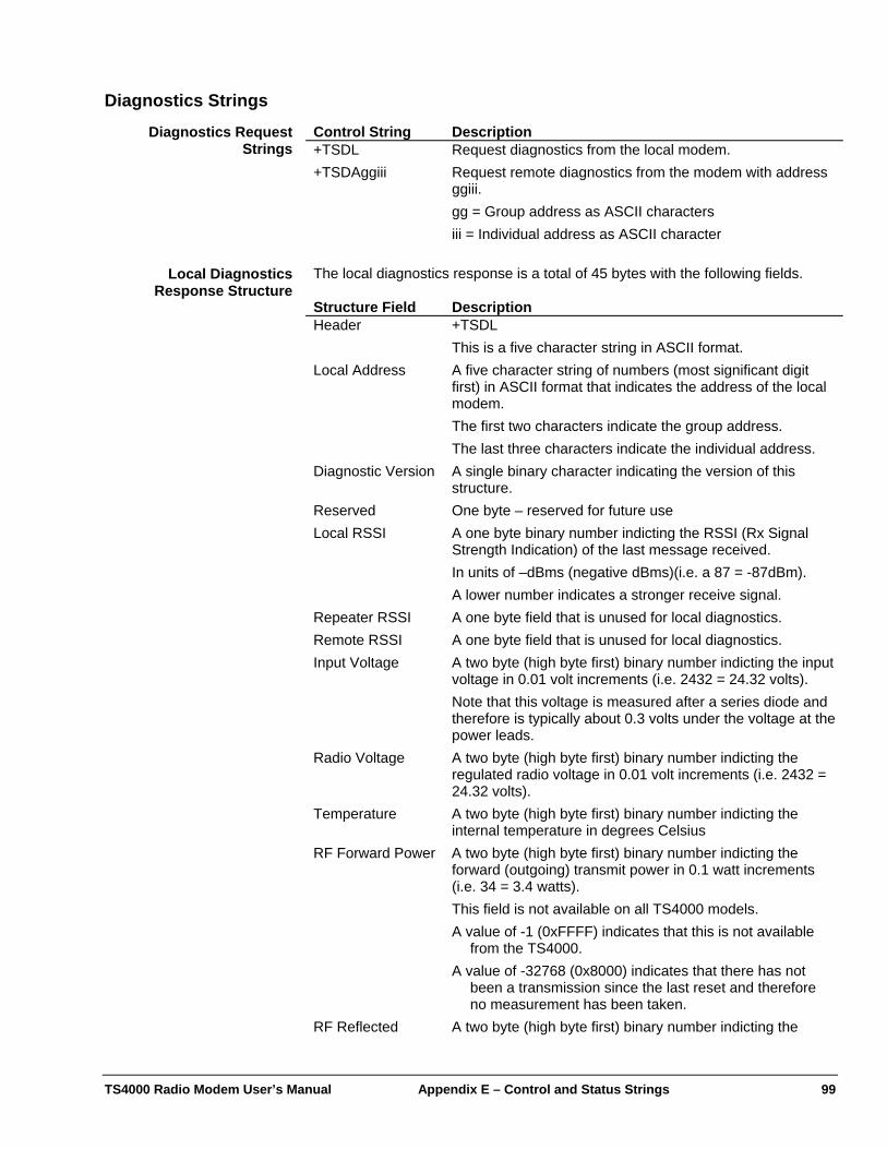
TS4000 Radio Modem User’s Manual Appendix E – Control and Status Strings 99
Diagnostics Strings Control String Description Diagnostics Request
Strings +TSDL Request diagnostics from the local modem. +TSDAggiii Request remote diagnostics from the modem with address
ggiii. gg = Group address as ASCII characters iii = Individual address as ASCII character
The local diagnostics response is a total of 45 bytes with the following fields. Local Diagnostics
Response Structure Structure Field Description Header +TSDL
This is a five character string in ASCII format. Local Address A five character string of numbers (most significant digit
first) in ASCII format that indicates the address of the local modem. The first two characters indicate the group address. The last three characters indicate the individual address.
Diagnostic Version A single binary character indicating the version of this structure.
Reserved One byte – reserved for future use Local RSSI A one byte binary number indicting the RSSI (Rx Signal
Strength Indication) of the last message received. In units of –dBms (negative dBms)(i.e. a 87 = -87dBm). A lower number indicates a stronger receive signal.
Repeater RSSI A one byte field that is unused for local diagnostics. Remote RSSI A one byte field that is unused for local diagnostics. Input Voltage A two byte (high byte first) binary number indicting the input
voltage in 0.01 volt increments (i.e. 2432 = 24.32 volts). Note that this voltage is measured after a series diode and therefore is typically about 0.3 volts under the voltage at the power leads.
Radio Voltage A two byte (high byte first) binary number indicting the regulated radio voltage in 0.01 volt increments (i.e. 2432 = 24.32 volts).
Temperature A two byte (high byte first) binary number indicting the internal temperature in degrees Celsius
RF Forward Power A two byte (high byte first) binary number indicting the forward (outgoing) transmit power in 0.1 watt increments (i.e. 34 = 3.4 watts). This field is not available on all TS4000 models. A value of -1 (0xFFFF) indicates that this is not available
from the TS4000. A value of -32768 (0x8000) indicates that there has not
been a transmission since the last reset and therefore no measurement has been taken.
RF Reflected A two byte (high byte first) binary number indicting the
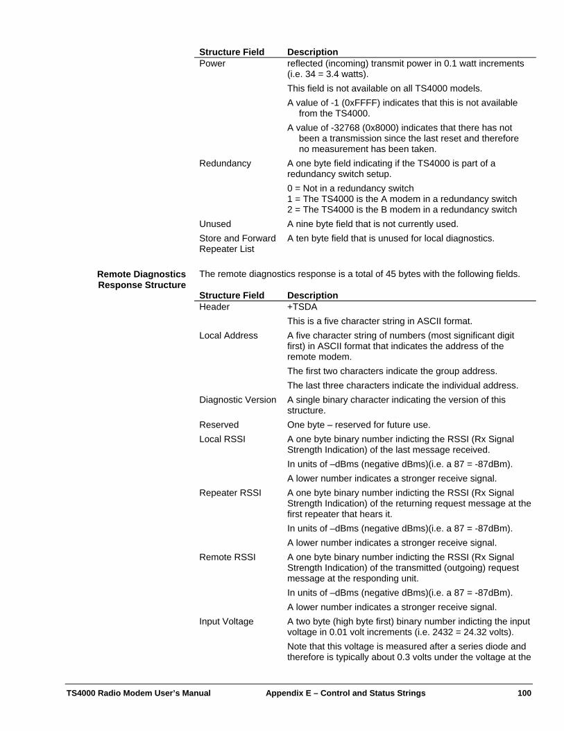
TS4000 Radio Modem User’s Manual Appendix E – Control and Status Strings 100
Structure Field Description Power reflected (incoming) transmit power in 0.1 watt increments
(i.e. 34 = 3.4 watts). This field is not available on all TS4000 models. A value of -1 (0xFFFF) indicates that this is not available
from the TS4000. A value of -32768 (0x8000) indicates that there has not
been a transmission since the last reset and therefore no measurement has been taken.
Redundancy A one byte field indicating if the TS4000 is part of a redundancy switch setup. 0 = Not in a redundancy switch 1 = The TS4000 is the A modem in a redundancy switch 2 = The TS4000 is the B modem in a redundancy switch
Unused A nine byte field that is not currently used. Store and Forward Repeater List
A ten byte field that is unused for local diagnostics.
The remote diagnostics response is a total of 45 bytes with the following fields. Remote Diagnostics
Response Structure Structure Field Description Header +TSDA
This is a five character string in ASCII format. Local Address A five character string of numbers (most significant digit
first) in ASCII format that indicates the address of the remote modem. The first two characters indicate the group address. The last three characters indicate the individual address.
Diagnostic Version A single binary character indicating the version of this structure.
Reserved One byte – reserved for future use. Local RSSI A one byte binary number indicting the RSSI (Rx Signal
Strength Indication) of the last message received. In units of –dBms (negative dBms)(i.e. a 87 = -87dBm). A lower number indicates a stronger receive signal.
Repeater RSSI A one byte binary number indicting the RSSI (Rx Signal Strength Indication) of the returning request message at the first repeater that hears it. In units of –dBms (negative dBms)(i.e. a 87 = -87dBm). A lower number indicates a stronger receive signal.
Remote RSSI A one byte binary number indicting the RSSI (Rx Signal Strength Indication) of the transmitted (outgoing) request message at the responding unit. In units of –dBms (negative dBms)(i.e. a 87 = -87dBm). A lower number indicates a stronger receive signal.
Input Voltage A two byte (high byte first) binary number indicting the input voltage in 0.01 volt increments (i.e. 2432 = 24.32 volts). Note that this voltage is measured after a series diode and therefore is typically about 0.3 volts under the voltage at the
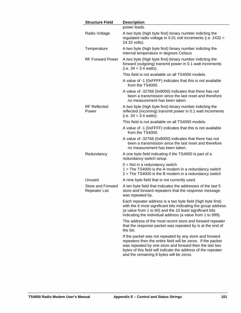
TS4000 Radio Modem User’s Manual Appendix E – Control and Status Strings 101
Structure Field Description power leads.
Radio Voltage A two byte (high byte first) binary number indicting the regulated radio voltage in 0.01 volt increments (i.e. 2432 = 24.32 volts).
Temperature A two byte (high byte first) binary number indicting the internal temperature in degrees Celsius
RF Forward Power A two byte (high byte first) binary number indicting the forward (outgoing) transmit power in 0.1 watt increments (i.e. 34 = 3.4 watts). This field is not available on all TS4000 models. A value of -1 (0xFFFF) indicates that this is not available
from the TS4000. A value of -32768 (0x8000) indicates that there has not
been a transmission since the last reset and therefore no measurement has been taken.
RF Reflected Power
A two byte (high byte first) binary number indicting the reflected (incoming) transmit power in 0.1 watt increments (i.e. 34 = 3.4 watts). This field is not available on all TS4000 models. A value of -1 (0xFFFF) indicates that this is not available
from the TS4000. A value of -32768 (0x8000) indicates that there has not
been a transmission since the last reset and therefore no measurement has been taken.
Redundancy A one byte field indicating if the TS4000 is part of a redundancy switch setup. 0 = Not in a redundancy switch 1 = The TS4000 is the A modem in a redundancy switch 2 = The TS4000 is the B modem in a redundancy switch
Unused A nine byte field that is not currently used. Store and Forward Repeater List
A ten byte field that indicates the addresses of the last 5 store and forward repeaters that the response message was repeated by. Each repeater address is a two byte field (high byte first) with the 6 most significant bits indicating the group address (a value from 1 to 60) and the 10 least significant bits indicating the individual address (a value from 1 to 999). The address of the most recent store and forward repeater that the response packet was repeated by is at the end of the list. If the packet was not repeated by any store and forward repeaters then the entire field will be zeros. If the packet was repeated by one store and forward then the last two bytes of this field will indicate the address of the repeater and the remaining 8 bytes will be zeros.
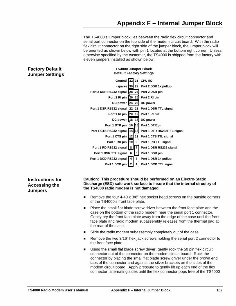
TS4000 Radio Modem User’s Manual Appendix F – Internal Jumper Block 102
Appendix F – Internal Jumper Block
The TS4000’s jumper block lies between the radio flex circuit connector and serial port connector on the top side of the modem circuit board. With the radio flex circuit connector on the right side of the jumper block, the jumper block will be oriented as shown below with pin 1 located at the bottom right corner. Unless otherwise specified by the customer, the TS4000 is shipped from the factory with eleven jumpers installed as shown below.
Factory Default Jumper Settings
Port 1 DTR RS232/TTL signal
1
3
5
7
9
11
13
15
25
27
29
17
19
21
23
31
2
4
6
8
10
12
14
16
26
28
30
18
20
22
24
32 CPU I/O
Port 2 DSR 1k pullup
Port 2 DSR pin
Port 2 RI pinPort 2 RI pin
DC power
DC powerDC power
DC power
Port 2 DSR RS232 signal
Port 1 DSR TTL signal
Port 1 RI pin
Port 1 DTR pinPort 1 DTR pin
Port 1 RI pin
Port 1 DSR RS232 signal
Port 1 CTS TTL signal
Port 1 RD TTL signal
Port 1 DSR RS232 signal
Port 1 DSR pin
Port 1 DSR 1k pullup
Port 1 DCD TTL signal
Port 1 CTS RS232 signal
Port 1 CTS pin
Port 1 RD pin
Port 1 RD RS232 signal
Port 1 DSR TTL signal
Port 1 DCD RS232 signal
Port 1 DCD pin
Ground
(spare)
TS4000 Jumper BlockDefault Factory Settings
Caution: This procedure should be performed on an Electro-Static Discharge (ESD) safe work surface to insure that the internal circuitry of the TS4000 radio modem is not damaged.
Instructions for Accessing the Jumpers
Remove the four 4-40 x 3/8” hex socket head screws on the outside corners of the TS4000’s front face plate.
Place the small flat blade screw driver between the front face plate and the case on the bottom of the radio modem near the serial port 1 connector. Gently pry the front face plate away from the edge of the case until the front face plate and radio modem subassembly releases from the thermal pad at the rear of the case.
Slide the radio modem subassembly completely out of the case. Remove the two 3/16” hex jack screws holding the serial port 2 connector to
the front face plate. Using the small flat blade screw driver, gently rock the 50 pin flex circuit
connector out of the connector on the modem circuit board. Rock the connector by placing the small flat blade screw driver under the brown end tabs of the connector and against the silver brackets on the sides of the modem circuit board. Apply pressure to gently lift up each end of the flex connector, alternating sides until the flex connector pops free of the TS4000
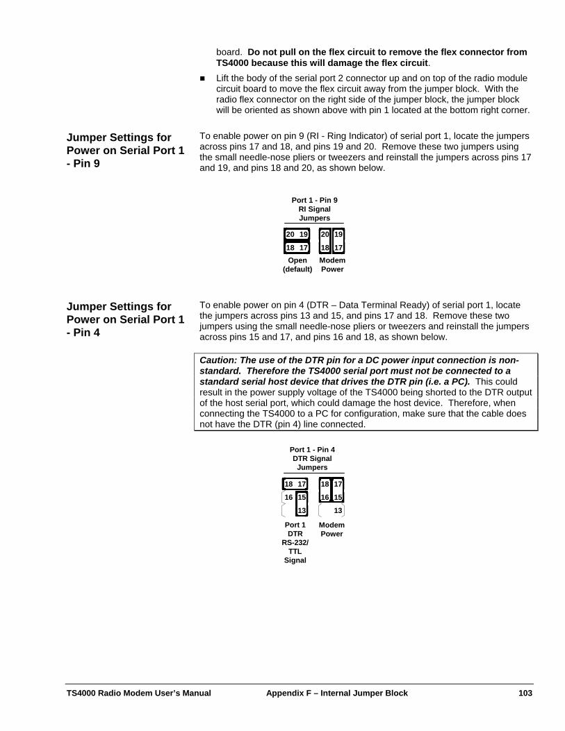
TS4000 Radio Modem User’s Manual Appendix F – Internal Jumper Block 103
board. Do not pull on the flex circuit to remove the flex connector from TS4000 because this will damage the flex circuit.
Lift the body of the serial port 2 connector up and on top of the radio module circuit board to move the flex circuit away from the jumper block. With the radio flex connector on the right side of the jumper block, the jumper block will be oriented as shown above with pin 1 located at the bottom right corner.
To enable power on pin 9 (RI - Ring Indicator) of serial port 1, locate the jumpers across pins 17 and 18, and pins 19 and 20. Remove these two jumpers using the small needle-nose pliers or tweezers and reinstall the jumpers across pins 17 and 19, and pins 18 and 20, as shown below.
Jumper Settings for Power on Serial Port 1 - Pin 9
Port 1 - Pin 9RI SignalJumpers
Open(default)
ModemPower
19
17
20
18
19
17
20
18
To enable power on pin 4 (DTR – Data Terminal Ready) of serial port 1, locate the jumpers across pins 13 and 15, and pins 17 and 18. Remove these two jumpers using the small needle-nose pliers or tweezers and reinstall the jumpers across pins 15 and 17, and pins 16 and 18, as shown below.
Jumper Settings for Power on Serial Port 1 - Pin 4
Caution: The use of the DTR pin for a DC power input connection is non-standard. Therefore the TS4000 serial port must not be connected to a standard serial host device that drives the DTR pin (i.e. a PC). This could result in the power supply voltage of the TS4000 being shorted to the DTR output of the host serial port, which could damage the host device. Therefore, when connecting the TS4000 to a PC for configuration, make sure that the cable does not have the DTR (pin 4) line connected.
Port 1 - Pin 4DTR Signal
Jumpers
Port 1DTR
RS-232/TTL
Signal
ModemPower
15
13
16
18 17
15
13
16
18 17
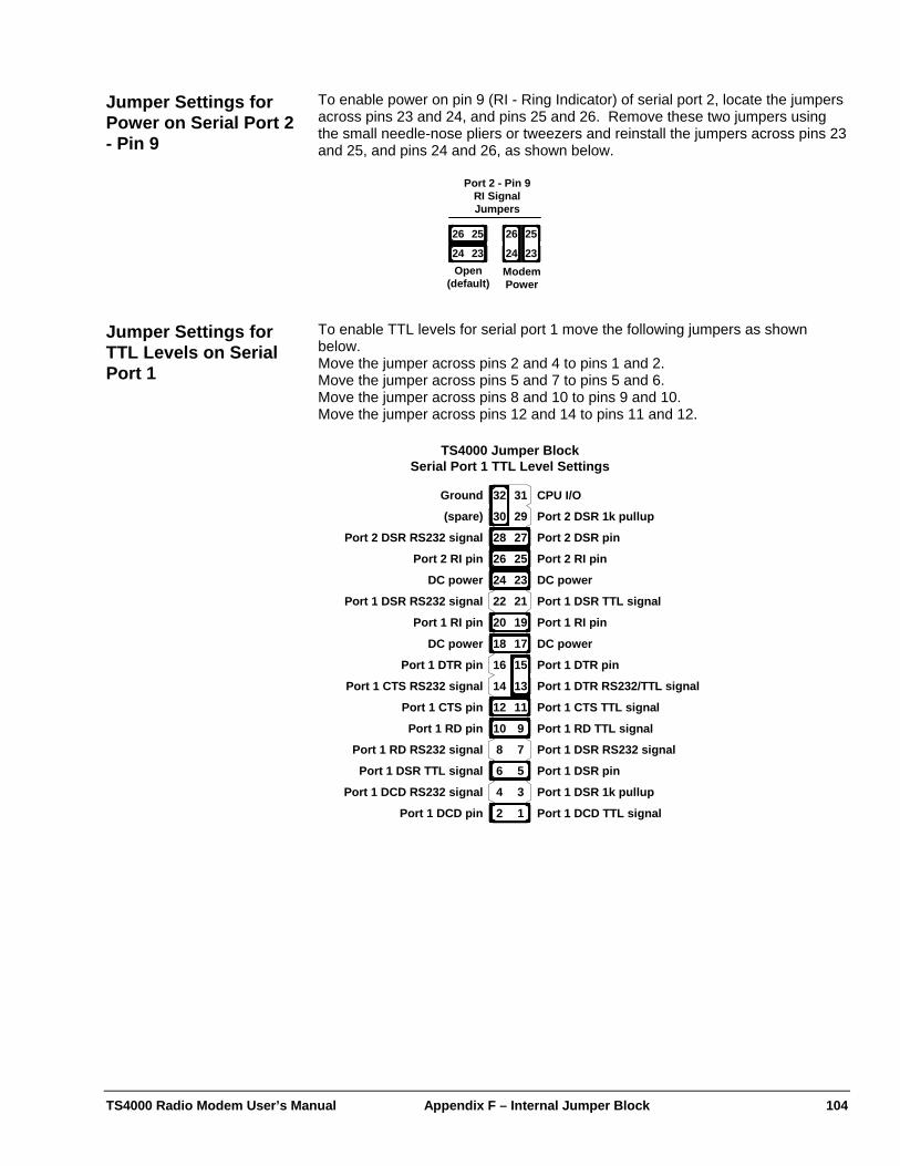
TS4000 Radio Modem User’s Manual Appendix F – Internal Jumper Block 104
To enable power on pin 9 (RI - Ring Indicator) of serial port 2, locate the jumpers across pins 23 and 24, and pins 25 and 26. Remove these two jumpers using the small needle-nose pliers or tweezers and reinstall the jumpers across pins 23 and 25, and pins 24 and 26, as shown below.
Jumper Settings for Power on Serial Port 2 - Pin 9
Port 2 - Pin 9RI SignalJumpers
Open(default)
ModemPower
25
23
26
24
25
23
26
24
To enable TTL levels for serial port 1 move the following jumpers as shown below.
Jumper Settings for TTL Levels on Serial Port 1 Move the jumper across pins 2 and 4 to pins 1 and 2.
Move the jumper across pins 5 and 7 to pins 5 and 6. Move the jumper across pins 8 and 10 to pins 9 and 10. Move the jumper across pins 12 and 14 to pins 11 and 12.
Port 1 DTR RS232/TTL signal
1
3
5
7
9
11
13
15
25
27
29
17
19
21
23
31
2
4
6
8
10
12
14
16
26
28
30
18
20
22
24
32 CPU I/O
Port 2 DSR 1k pullup
Port 2 DSR pin
Port 2 RI pinPort 2 RI pin
DC power
DC powerDC power
DC power
Port 2 DSR RS232 signal
Port 1 DSR TTL signal
Port 1 RI pin
Port 1 DTR pinPort 1 DTR pin
Port 1 RI pin
Port 1 DSR RS232 signal
Port 1 CTS TTL signal
Port 1 RD TTL signal
Port 1 DSR RS232 signal
Port 1 DSR pin
Port 1 DSR 1k pullup
Port 1 DCD TTL signal
Port 1 CTS RS232 signal
Port 1 CTS pin
Port 1 RD pin
Port 1 RD RS232 signal
Port 1 DSR TTL signal
Port 1 DCD RS232 signal
Port 1 DCD pin
Ground
(spare)
TS4000 Jumper BlockSerial Port 1 TTL Level Settings
TS4000 Radio Modem User’s Manual Appendix G – FCC MURS Rules 105
Appendix G – FCC MURS Rules
For information on using the TS4000 under the FCC’s unlicensed MURS rules see the Licensing – Unlicensed Operation section above. Notes:
1) The rules for MURS first went into effect on November 13, 2000. 2) The FCC may change, add, restrict or modify these rules in the future. 3) A number of changes to the MURS rules were made in October of 2002.
The following is a copy of the FCC Rules that pertain to MURS operation.
FCC Rules – 2005 Code of the Federal Regulations Part 95 of Title 47 Revised as of October 1, 2005
95.401 (CB Rule 1) What are the Citizens Band Radio Services? The Citizens Band Radio Services are: * * * * * (f) The Multi-Use Radio Service (MURS)--a private, two-way, short distance voice or data communications service for personal or business activities of the general public. The rules for this service are contained in subpart J of this part.
95.601 Basis and purpose. * * * The Personal Radio Services are the GMRS (General Mobile Radio Service)-subpart A, the Family Radio Service (FRS)-subpart B, the R/C(Radio Control Radio Service)-subpart C, the CB (Citizens Band Radio Service)-subpart D, the Low Power Radio Service (LPRS)-subpart G, the Wireless Medical Telemetry Service (WMTS)-subpart H, the Medical Implants Communication Service (MICS)-subpart I, and the Multi-Use Radio Service (MURS)--subpart J. 95.603 Certification required. (g) Each Multi-Use Radio Service transmitter (a transmitter that operates or is intended to operate in the MURS) must be certificated in accordance with Subpart J of Part 2 of this chapter, Provided however, that those radio units certificated as of November 12, 2002 need not be recertificated. 95.605 Certification procedures. Any entity may request certification for its transmitter when the transmitter is used in the GMRS, FRS, R/C, CB, IVDS, LPRS, MURS, or MICS following the procedures in part 2 of this chapter. * * * 95.631 Emission types. (j) A MURS transmitter must transmit only A1D, A2B, A2D, A3E, F2B, F1D, F2D, F3E, G3E. Emission types A3E, F3E and G3E include selective calling or tone-operated squelch tones to establish or continue voice communications. MURS transmitters are prohibited from transmitting in the continuous carrier mode. 95.632 MURS transmitter frequencies. (a) The MURS transmitter channel frequencies are 151.820MHz, 151.880MHz, 151.940MHz, 154.570MHz, 154.600MHz. (b) The authorized bandwidth is 11.25kHz on frequencies 151.820MHz, 151.880MHz and 151.940MHz. The authorized bandwidth is 20.0kHz on frequencies 154.570MHz and 154.600MHz. (c) MURS transmitters must maintain a frequency stability of 5.0 ppm, or 2.0 ppm if designed to operate with a 6.25kHz bandwidth. 95.633 Emission bandwidth. (f) The authorized bandwidth for any emission type transmitted by a MURS transmitter is specified as follows: (1) Emissions on frequencies 151.820MHz, 151.880MHz and 151.940MHz are limited to 11.25KHz. (2) Emissions on frequencies 154.570MHz and 154.600MHz are limited to 20.0KHz. (3) Provided, however, that all A3E emissions are limited to 8KHz.
TS4000 Radio Modem User’s Manual Appendix G – FCC MURS Rules 106
95.635 Unwanted radiation. (e) For transmitters designed to operate in the MURS, transmitters shall comply with the following: * * * * * 95.639 Maximum transmitter power. (h) No MURS unit, under any condition of modulation, shall exceed 2 Watts transmitter power output. 95.649 Power capability No CB, R/C, LPRS, FRS, MICS, MURS or WMTS unit shall incorporate provisions for increasing its transmitter power to any level in excess of the limits specified in 95.639. 95.651 Crystal control required All transmitters used in the Personal Radio Services must be crystal controlled, except an R/C station that transmits in the 26-27 MHz frequency band, a FRS unit, a LPRS unit, a MURS unit, a MICS transmitter, or a WMTS unit.
Subpart J-Multi-Use Radio Service (MURS) General Provisions 95.1301 Eligibility. An entity is authorized by rule to operate a MURS transmitter if it is not a foreign government or a representative of a foreign government and if it uses the transmitter in accordance with 95.1309 and otherwise operates in accordance with the rules contained in this subpart. No license will be issued. 95.1303 Authorized locations. (a) MURS operation is authorized: (1) Anywhere CB station operation is permitted under 95.405; and (2) Aboard any vessel of the United States, with the permission of the captain, while the vessel is traveling either domestically or in international waters. (b) MURS operation is not authorized aboard aircraft in flight. (c) Anyone intending to operate a MURS unit on the islands of Puerto Rico, Desecheo, Mona, Vieques, and Culebra in a manner that could pose an interference threat to the Arecibo Observatory shall notify the Interference Office, Arecibo Observatory, Post Office Box 995, Arecibo, Puerto Rico 00613, in writing or electronically, of the location of the unit. Operators may wish to consult interference guidelines, which will be provided by Cornell University. Operators who choose to transmit information electronically should e-mail to: [email protected]. (1) The notification to the Interference Office, Arecibo Observatory shall be made 45 days prior to commencing operation of the unit. The notification shall state the geographical coordinates of the unit. (2) After receipt of such notifications, the Commission will allow the Arecibo Observatory a period of 20 days for comments or objections. The operator will be required to make reasonable efforts in order to resolve or mitigate any potential interference problem with the Arecibo Observatory. If the Commission determines that an operator has satisfied its responsibility to make reasonable efforts to protect the Observatory from interference, the unit may be allowed to operate. 95.1305 Station identification. A MURS station is not required to transmit a station identification announcement. 95.1307 Permissible communications. (a) MURS stations may transmit voice or data signals as permitted in this subpart. (b) A MURS station may transmit any emission type listed in 95.631(j) of this chapter. (c) MURS frequencies may be used for remote control and telemetering functions. MURS transmitters may not be operated in the continuous carrier transmit mode. 95.1309 Channel use policy. (a) The channels authorized to MURS systems by this part are available on a shared basis only and will not be assigned for the exclusive use of any entity. (b) Those using MURS transmitters must cooperate in the selection and use of channels in order to reduce interference and make the most effective use of authorized facilities. Channels must be selected in an effort to avoid interference to other MURS transmissions. 95.1311 Repeater operations an signal boosters prohibited. MURS stations are prohibited from operating as a repeater station or as a signal booster. This prohibition include store-and-forward packet operation. 95.1313 Interconnection prohibited.
TS4000 Radio Modem User’s Manual Appendix G – FCC MURS Rules 107
MURS stations are prohibited from interconnection with the public switched network. Interconnection Defined. Connection through automatic or manual means of multi-use radio stations with the facilities of the public switched telephone network to permit the transmission of messages or signals between points in the wireline or radio network of a public telephone company and persons served by multi-use radio stations. Wireline or radio circuits or links furnished by common carriers, which are used by licensees or other authorized persons for transmitter control (including dial-up transmitter control circuits) or as an integral part of an authorized, private, internal system of communication or as an integral part of dispatch point circuits in a multi-use radio station are not considered to be interconnection for purposes of this rule part. 95.1315 Antenna height restriction. The highest point of any MURS antenna must be no more than 18.3 meters (60 feet) above the ground or 6.10 meters (20 feet) above the highest point of the structure on which it is mounted. 95.1317 Grandfathered MURS stations. Stations that were licensed under Part 90 of the Commission’s Rules to operate on MURS frequencies as of November 13, 2000, are granted a license by rule that authorizes continued operations under the terms of such nullified part 90 authorizations, including any rule waivers.