ts19751 user manual - taiwan semiconductor component count, simplifying emi design and lowering the...
TRANSCRIPT

TS19751 USER MANUAL
A1605

FEATURES :
● Built-in Power MOSFET ● Constant current accuracy <±3% ● Gate Output Voltage Clamp ● Peak Current Mode Control ● LED Open Protection(OLP) ● Over Current Protection (OCP) ● Internal Over Thermal Protection (OTP) ● Start-up time < 500ms ● Low Cost

DESCRIPTION
━ : Input Voltage Waveform
━ : Peak Current Waveform for Inductor
━ : Charging Current Waveform for Inductor
━ : Flywheel Diode Waveform
━ : Output Current Waveform
━ : MOSFET Gate Waveform
The TS19751 is a high performance LED driver which accuracy constant current PWM controller with high voltage power MOSFET integrated. It achieves high accuracy by peak current mode. The device provide high efficiency along with a number of key built-in protection features while minimizing the external component count, simplifying EMI design and lowering the total bill of material cost. TS19751 also achieving excellent line and load regulation. Pulse-by-pulse waveform analysis allows for a loop response that is much faster than traditional solutions, resulting in improved dynamic load response. The built-in current limit function enables optimized transformer design in universal off-line applications over a wide input voltage range.

PIN DESCRIPTION AND FUNCTION BLOCK
PIN NO. NAME FUNCTION
1,8 GND Ground return for all internal circuitry.
2 Vcc Power supply pin for all internal circuitry.
3,4 CS Input current sense pin.
5,6 Drain Drain of internal HV MOS.
7 H.V HV start up pin
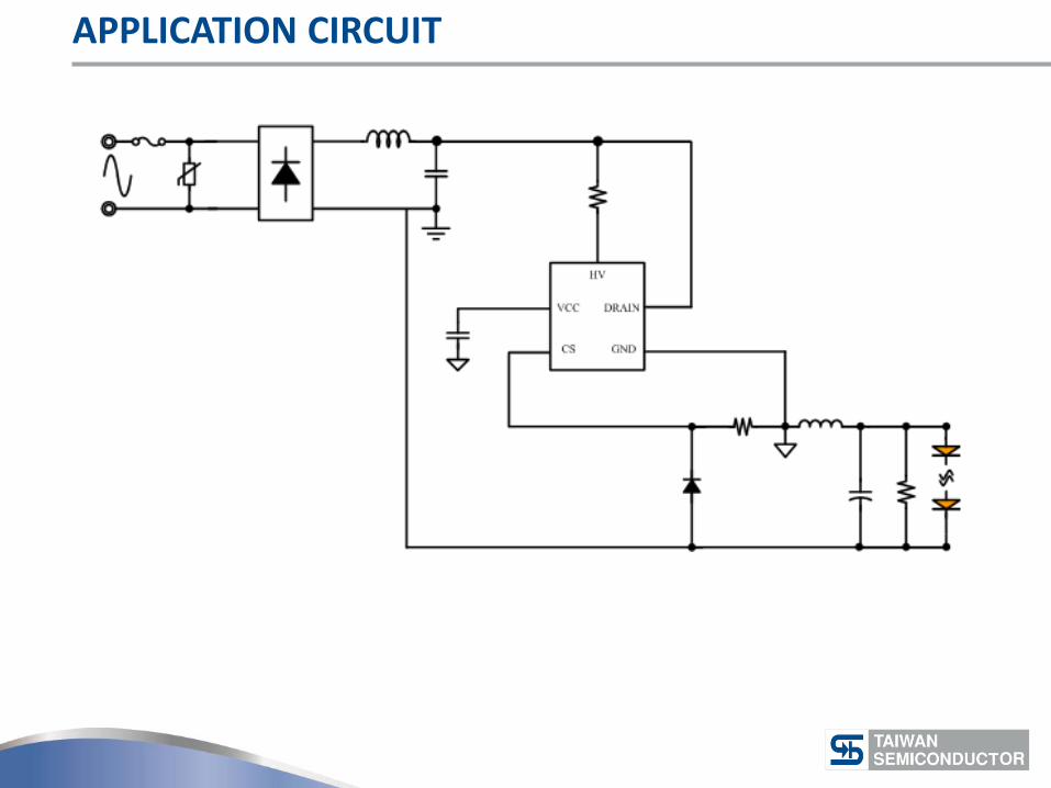
APPLICATION CIRCUIT

BUCK PRINCIPLE – MOSFET TURN ON
MOSFET Turn ON

BUCK PRINCIPLE – MOSFET TURN OFF
MOSFET Turn Off
IOUT = 200mV / RCS

DESIGN SAMPLE
P09.
Input : 90Vac ~ 264Vac / 50Hz~60Hz Output : 100V / 50mA

CALCULATION FORM – PARAMETER KEY IN
P09.
=>Key in
=>Output
Key in Input/Output and Frequency Value Note : adjust Frequency Value Avoid Frenquency at Vac_max too fast
Minimum Vac Voltage 最低輸入電壓 220 Vrms
Maximun Vac Voltage 最高輸入電壓 240 Vrms
LED Output Voltage LED 輸出電壓 100 V
LED output Current LED 輸出電流 0.05 A
Fsw at Vac_min 最低輸入電壓之系統切換頻率 50 Khz

CALCULATION FORM – PARAMETER KEY IN
P09.
=>Key in
=>Output
VHV = Vdc_bus – IopA * RHV VCC = VHV→ Ic Regulator Set VO_OVP : VO_OVP (Typ) = IopA (Typ) * RL VO_OVP (MAX) = IopA (MAX) * RL
LED Open Voltage 輸出開路電壓 設定值 123 V
Dammy Resistance Value 電阻值 61.5 kΩ
CALCULATION FORM – BUCK- OPERATION PARAMETER
P09.
=>Key in
=>Output
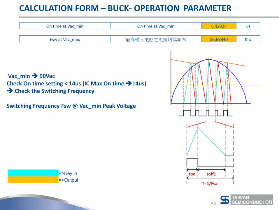
Vac_min 90Vac Check On time setting < 14us (IC Max On time 14us) Check the Switching Frequency Switching Frequency Fsw @ Vac_min Peak Voltage
Fsw at Vac_max 最高輸入電壓之系統切換頻率 56.69840 Khz
On time at Vac_min On time at Vac_min 6.42824 us

CALCULATION FORM– INDUCTOR DESIGN
P09.
=>Key in
=>Output
Ae Value Choose EE10 Core Ae =12.1 mm^2
EE10/11 PC40 10.2*5.5*4.75 0.0287 12.10 23.70 850.00 26.60 302.00 1.50
EE13 PC40 13.0*6.0*6.15 0.0570 17.10 33.35 1130.00 30.20 517.00 2.70
EE16 PC40 16*7.2*4.8 0.0765 19.20 39.85 1140.00 35.00 672.00 3.30
EE19 PC40 19.1*7.95*5.0 0.1243 23.00 54.04 1250.00 39.40 900.00 4.80
EE19/16 PC40 19.29*8.1*4.75 0.1191 22.40 53.15 1350.00 39.10 882.00 4.80
EE20/20/5 PC40 20.15*10*5.1 0.1572 31.00 50.70 1460.00 43.00 1340.00 7.50
EE22 PC40 22*9.35*5.75 0.1590 41.00 38.79 2180.00 39.40 1610.00 8.80
Ae Value of the Core 鐵芯Ae值 12.1 mm^2
Maximum Flux Density (Bmax) 最大操作磁通 Bmax 3300 Gauss

CALCULATION FORM – INDUCTOR DESIGN
P09.
=>Key in
=>Output
Flux density Choose PC40 Material 120℃ Bs Value is About 350mT Setting Maximum Flux Density 330mT = 3300Gauss
Ae Value of the Core 鐵芯Ae值 13 mm^2
Maximum Flux Density (Bmax) 最大操作磁通 Bmax 3400 Gauss

CALCULATION FORM – TRANSFORMER TURNS
P09.
=>Key in
=>Output
Condition Vac_min 90Vac
Inductor Peak Current at Vac_min 最低輸入電壓之電感峰值電流 0.10000 A
Minimum Turns of the Inductor 電感最少圈數值 342.72 Turns
real Turns 實際圈數 370 Turns
Saturation Current 飽和電流 0.11 A

CALCULATION FORM – LED OPEN OVP SETTING
P09.
=>Key in
=>Output
Check VOUT_OVP > 120~130% x VOUT 120V~130V > 123% x 100V =123V
LED Open Voltage 輸出開路電壓 設定值 123 V
Dammy Resistance Value 電阻值 61.5 kΩ
The open load protection will shut the gate driver when minimum off time keep shorter than 4.5uS.

CALCULATION FORM – KEY COMPONENT VOLTAGE STRESS
P09.
=>Key in
=>Output
Voltage Stress on 2nd Diode Diodes最低耐壓 373.4 V
Voltage Stress on MOSFE MOS_Off電壓 373.4 V

CALCULATION FORM – LED OPEN OVP SETTING
P09.
=>Key in
=>Output
Suggest RCS Value
RCS = 200mV / IOUT
CS Resistance Value CS 電阻值 4.000 Ω

TRANSFORMER DESIGN
P09.
NP
Core ROUNDING TAPE COPPER SHIELD Bobbin
Core
No. Thermal
Wire Turns Winding Method S F
NP 1 4 0.12mm x 1P 370 Solenoid winding
Insulation : Polyster Tape t=0.05mm, 2Layer
Core EE10 Bobbin EE10
TOP
Bottom
STATR
Pin Sepcification Remark
Primary Side Inductance 1<=>4 13.5mH+/1 10% 100KHz, 1V

TS19751 DEMO BOARD ELECTRICAL CIRCUIT

TS19751 DEMO BOARD
Design case of demoboard

TS19751 DEMO BOARD TEST RESULT
P10.
Vin Iout(mA) PF EFF(%) Vout W
200 46 0.475 90.27 99.87 5.089
220 46 0.452 89.67 99.862 5.123
230 46 0.443 88.46 99.654 5.182
264 46 0.934 88.31 99.689 5.193
0
5
10
15
20
25
30
35
40
45
50
200 220 230 264
80.00
85.00
90.00
95.00
200 220 230 264
Ou
tpu
t C
urr
en
t (m
A)
Effi
cie
ncy
(%
)
Vac (V) Vac (V)

THANK YOU Taiwan Semiconductor Co., Ltd. Headquarters Address: 11F. No. 25 Sec. 3, Beishin Rd, Shindian District, New Taipei City, Taiwan R.O.C. Telephone: +886-2-8913-1788 E-mail: [email protected] Website: www.taiwansemi.com