ts_125212v051000p_release5_multiplexing and channel coding (fdd)
TRANSCRIPT

7/31/2019 Ts_125212v051000p_release5_Multiplexing and Channel Coding (FDD)
http://slidepdf.com/reader/full/ts125212v051000prelease5multiplexing-and-channel-coding-fdd 1/74
ETSI TS 125 212 V5.10.0 (2005-06)
Technical Specification
Universal Mobile Telecommunications System (UMTS);Multiplexing and channel coding (FDD)
(3GPP TS 25.212 version 5.10.0 Release 5)
7/31/2019 Ts_125212v051000p_release5_Multiplexing and Channel Coding (FDD)
http://slidepdf.com/reader/full/ts125212v051000prelease5multiplexing-and-channel-coding-fdd 2/74
ETSI
ETSI TS 125 212 V5.10.0 (2005-06)13GPP TS 25.212 version 5.10.0 Release 5
ReferenceRTS/TSGR-0125212v5a0
Keywords
UMTS
ETSI
650 Route des LuciolesF-06921 Sophia Antipolis Cedex - FRANCE
Tel.: +33 4 92 94 42 00 Fax: +33 4 93 65 47 16
Siret N°348 623 562 00017 - NAF 742 CAssociation à but non lucratif enregistrée à laSous-Préfecture de Grasse (06) N°7803/88
Important notice
Individual copies of the present document can be downloaded from:http://www.etsi.org
The present document may be made available in more than one electronic version or in print. In any case of existing orperceived difference in contents between such versions, the reference version is the Portable Document Format (PDF).
In case of dispute, the reference shall be the printing on ETSI printers of the PDF version kept on a specific network drivewithin ETSI Secretariat.
Users of the present document should be aware that the document may be subject to revision or change of status.Information on the current status of this and other ETSI documents is available at
http://portal.etsi.org/tb/status/status.asp
If you find errors in the present document, please send your comment to one of the following services:http://portal.etsi.org/chaircor/ETSI_support.asp
Copyright Notification
No part may be reproduced except as authorized by written permission.The copyright and the foregoing restriction extend to reproduction in all media.
© European Telecommunications Standards Institute 2005.All rights reserved.
DECTTM
, PLUGTESTSTM
and UMTSTM
are Trade Marks of ETSI registered for the benefit of its Members.TIPHON
TMand the TIPHON logo are Trade Marks currently being registered by ETSI for the benefit of its Members.
3GPPTM is a Trade Mark of ETSI registered for the benefit of its Members and of the 3GPP Organizational Partners.

7/31/2019 Ts_125212v051000p_release5_Multiplexing and Channel Coding (FDD)
http://slidepdf.com/reader/full/ts125212v051000prelease5multiplexing-and-channel-coding-fdd 3/74
ETSI
ETSI TS 125 212 V5.10.0 (2005-06)23GPP TS 25.212 version 5.10.0 Release 5
Intellectual Property Rights
IPRs essential or potentially essential to the present document may have been declared to ETSI. The information
pertaining to these essential IPRs, if any, is publicly available for ETSI members and non-members, and can be found
in ETSI SR 000 314: "Intellectual Property Rights (IPRs); Essential, or potentially Essential, IPRs notified to ETSI inrespect of ETSI standards", which is available from the ETSI Secretariat. Latest updates are available on the ETSI Web
server (http://webapp.etsi.org/IPR/home.asp).
Pursuant to the ETSI IPR Policy, no investigation, including IPR searches, has been carried out by ETSI. No guaranteecan be given as to the existence of other IPRs not referenced in ETSI SR 000 314 (or the updates on the ETSI Web
server) which are, or may be, or may become, essential to the present document.
Foreword
This Technical Specification (TS) has been produced by ETSI 3rd Generation Partnership Project (3GPP).
The present document may refer to technical specifications or reports using their 3GPP identities, UMTS identities orGSM identities. These should be interpreted as being references to the corresponding ETSI deliverables.
The cross reference between GSM, UMTS, 3GPP and ETSI identities can be found under
http://webapp.etsi.org/key/queryform.asp .

7/31/2019 Ts_125212v051000p_release5_Multiplexing and Channel Coding (FDD)
http://slidepdf.com/reader/full/ts125212v051000prelease5multiplexing-and-channel-coding-fdd 4/74
ETSI
ETSI TS 125 212 V5.10.0 (2005-06)33GPP TS 25.212 version 5.10.0 Release 5
Contents
Intellectual Property Rights................................................................................................................................2
Foreword.............................................................................................................................................................2 Foreword.............................................................................................................................................................6
1 Scope ........................................................................................................................................................7
2 References ................................................................................................................................................7
3 Definitions, symbols and abbreviations ...................................................................................................7 3.1 Definitions..........................................................................................................................................................7 3.2 Symbols..............................................................................................................................................................8 3.3 Abbreviations ................................................................ ........................................................ .............................8
4 Multiplexing, channel coding and interleaving........................................................................................9 4.1 General ................................................... ............................................................ ................................................9 4.2 General coding/multiplexing of TrCHs................................................................ ..............................................9 4.2.1 CRC attachment........................................................... ............................................................ ...................13 4.2.1.1 CRC Calculation ......................................................... ........................................................ ..................13 4.2.1.2 Relation between input and output of the CRC attachment block................................................... ......13 4.2.2 Transport block concatenation and code block segmentation......................................... ............................14 4.2.2.1 Concatenation of transport blocks....... ............................................................ ......................................14 4.2.2.2 Code block segmentation ..................................................... ....................................................... ..........14 4.2.3 Channel coding ........................................................ ........................................................ ...........................15 4.2.3.1 Convolutional coding................................................ ........................................................... .................15 4.2.3.2 Turbo coding.............................................. .................................................... .......................................16 4.2.3.2.1 Turbo coder .............................................. .................................................... ...................................16 4.2.3.2.2 Trellis termination for Turbo coder ........................................................ .........................................17 4.2.3.2.3 Turbo code internal interleaver.................................... ........................................................... .........17 4.2.3.3 Concatenation of encoded blocks........................... ........................................................ .......................21 4.2.4 Radio frame size equalisation ....................................................... ..................................................... .........21 4.2.5 1
stinterleaving ................................................................ .......................................................... ..................21
4.2.5.1 Void.......................................................................................................................................................21 4.2.5.2 1st interleaver operation.........................................................................................................................21 4.2.5.3 Relation between input and output of 1st interleaving in uplink............................................................22 4.2.5.4 Relation between input and output of 1st interleaving in downlink.......................................................23 4.2.6 Radio frame segmentation ........................................................ ......................................................... .........23 4.2.6.1 Relation between input and output of the radio frame segmentation block in uplink ...........................23 4.2.6.2 Relation between input and output of the radio frame segmentation block in downlink ......................23 4.2.7 Rate matching ....................................................... ........................................................... ...........................23 4.2.7.1 Determination of rate matching parameters in uplink....................................................... ....................25 4.2.7.1.1 Determination of SF and number of PhCHs needed............................................. ...........................25 4.2.7.2 Determination of rate matching parameters in downlink ............................................................ ..........28 4.2.7.2.1 Determination of rate matching parameters for fixed positions of TrCHs ......................................28 4.2.7.2.2 Determination of rate matching parameters for flexible positions of TrCHs ..................................30 4.2.7.3 Bit separation and collection in uplink..... ................................................................. ............................32 4.2.7.3.1 Bit separation........................................ ............................................................ ...............................34 4.2.7.3.2 Bit collection .................................................... ............................................................. ..................34 4.2.7.4 Bit separation and collection in downlink........................................................ .....................................35 4.2.7.4.1 Bit separation........................................ ............................................................ ...............................36 4.2.7.4.2 Bit collection .................................................... ............................................................. ..................36 4.2.7.5 Rate matching pattern determination ............................................................ ........................................37 4.2.8 TrCH multiplexing................................................ ........................................................... ...........................38 4.2.9 Insertion of discontinuous transmission (DTX) indication bits .......................................................... ........38 4.2.9.1 1
stinsertion of DTX indication bits.......................................................................................................38
4.2.9.2 2nd insertion of DTX indication bits.............. ................................................................................ ........39 4.2.10 Physical channel segmentation .................................................................... ...............................................40 4.2.10.1 Relation between input and output of the physical segmentation block in uplink ................................40

7/31/2019 Ts_125212v051000p_release5_Multiplexing and Channel Coding (FDD)
http://slidepdf.com/reader/full/ts125212v051000prelease5multiplexing-and-channel-coding-fdd 5/74
ETSI
ETSI TS 125 212 V5.10.0 (2005-06)43GPP TS 25.212 version 5.10.0 Release 5
4.2.10.2 Relation between input and output of the physical segmentation block in downlink ...........................40 4.2.11 2nd interleaving............................................................................................................................................40 4.2.12 Physical channel mapping ...................................................... ........................................................... .........41 4.2.12.1 Uplink ..................................................... ........................................................... ...................................42 4.2.12.2 Downlink...............................................................................................................................................42 4.2.13 Restrictions on different types of CCTrCHs........... .................................................... ................................42
4.2.13.1 Uplink Dedicated channel (DCH) ........................................................... ..............................................42 4.2.13.2 Random Access Channel (RACH)................................................................. .......................................42 4.2.13.3 Void.......................................................................................................................................................43 4.2.13.4 Downlink Dedicated Channel (DCH) .............................................................. .....................................43 4.2.13.5 Void.......................................................................................................................................................43 4.2.13.6 Broadcast channel (BCH) ........................................................... ................................................ ..........43 4.2.13.7 Forward access and paging channels (FACH and PCH)...................................................... .................43 4.2.13.8 High Speed Downlink Shared Channel (HS-DSCH) associated with a DCH..................................... ..43 4.2.14 Multiplexing of different transport channels into one CCTrCH, and mapping of one CCTrCH onto
physical channels ............................................................. ......................................................... ..................43 4.2.14.1 Allowed CCTrCH combinations for one UE .................................................... ....................................44 4.2.14.1.1 Allowed CCTrCH combinations on the uplink ....................................................... ........................44 4.2.14.1.2 Allowed CCTrCH combinations on the downlink ............................................... ...........................44
4.3 Transport format detection ............................................................. ........................................................ ..........44 4.3.1 Blind transport format detection ......................................................... ........................................................45 4.3.1a Single transport format detection............................................................... .................................................45 4.3.2 Transport format detection based on TFCI ................................................. ................................................46 4.3.3 Coding of Transport-Format-Combination Indicator (TFCI) ....................................................... ..............46 4.3.4 Void ..................................................... ............................................................ ...........................................47 4.3.5 Mapping of TFCI words ....................................................... ..................................................... .................48 4.3.5.1 Mapping of TFCI word in normal mode.................................................. .............................................48 4.3.5.2 Mapping of TFCI word in compressed mode ............................................ ...........................................48 4.3.5.2.1 Uplink compressed mode ................................................ ....................................................... .........48 4.3.5.2.2 Downlink compressed mode ............................................ ....................................................... ........48 4.4 Compressed mode .............................................. .................................................... ..........................................49 4.4.1 Frame structure in the uplink .................................................................. ................................................... .49
4.4.2 Frame structure types in the downlink............................................................ ............................................50 4.4.3 Transmission time reduction method................................................................ ..........................................50 4.4.3.1 Void.......................................................................................................................................................50 4.4.3.2 Compressed mode by reducing the spreading factor by 2..................................................... ................50 4.4.3.3 Compressed mode by higher layer scheduling........ .................................................... ..........................50 4.4.4 Transmission gap position ............................................................... .......................................................... .51 4.5 Coding for HS-DSCH ................................................... ........................................................ ...........................52 4.5.1 CRC attachment for HS-DSCH ........................................................ ......................................................... .54 4.5.1a Bit scrambling for HS-DSCH ............................................................. ........................................................54 4.5.2 Code block segmentation for HS-DSCH ...................................................... ..............................................54 4.5.3 Channel coding for HS-DSCH.................................................... ....................................................... .........54 4.5.4 Hybrid ARQ for HS-DSCH........................................................... .................................................... .........54 4.5.4.1 HARQ bit separation.................. ................................................................. ..........................................55
4.5.4.2 HARQ First Rate Matching Stage................................. ............................................................... .........55 4.5.4.3 HARQ Second Rate Matching Stage .............................................................. ......................................55 4.5.4.4 HARQ bit collection ............................................................ ........................................................ .........56 4.5.5 Physical channel segmentation for HS-DSCH........................................ ....................................................57 4.5.6 Interleaving for HS-DSCH .................................................... ............................................................ .........57 4.5.7 Constellation re-arrangement for 16 QAM............................................................. ....................................58 4.5.8 Physical channel mapping for HS-DSCH.............................................................. .....................................58 4.6 Coding for HS-SCCH................................. ........................................................ ..............................................58 4.6.1 Overview ....................................................... .......................................................... ...................................59 4.6.2 HS-SCCH information field mapping ...................................................... ..................................................60 4.6.2.1 Redundancy and constellation version coding ............................................... .......................................60 4.6.2.2 Modulation scheme mapping ............................................ ........................................................... .........60 4.6.2.3 Channelization code-set mapping ........................................................... ..............................................60
4.6.2.4 UE identity mapping ................................................... ........................................................ ..................60 4.6.2.5 HARQ process identifier mapping........................................................... .............................................61 4.6.2.6 Transport block size index mapping .................................................. ...................................................61 4.6.3 Multiplexing of HS-SCCH information.......................... ............................................................ ................61
7/31/2019 Ts_125212v051000p_release5_Multiplexing and Channel Coding (FDD)
http://slidepdf.com/reader/full/ts125212v051000prelease5multiplexing-and-channel-coding-fdd 6/74
ETSI
ETSI TS 125 212 V5.10.0 (2005-06)53GPP TS 25.212 version 5.10.0 Release 5
4.6.4 CRC attachment for HS-SCCH ....................................................... .......................................................... .61 4.6.5 Channel coding for HS-SCCH....................... ........................................................ .....................................61 4.6.6 Rate matching for HS-SCCH..................... ............................................................ .....................................62 4.6.7 UE specific masking for HS-SCCH.............................. ............................................................. .................62 4.6.8 Physical channel mapping for HS-SCCH ......................................................... ..........................................62 4.7 Coding for HS-DPCCH.......... ........................................................... ..................................................... ..........62
4.7.1 Channel coding for HS-DPCCH......................................................... ....................................................... .63 4.7.1.1 Channel coding for HS-DPCCH HARQ-ACK ............................................................ .........................63 4.7.1.2 Channel coding for HS-DPCCH channel quality information ......................................................... .....63 4.7.2 Physical channel mapping for HS-DPCCH ........................................................... .....................................64
Annex A (informative): Blind transport format detection..................................................................65
A.1 Blind transport format detection using fixed positions ..........................................................................65 A.1.1 Blind transport format detection using received power ratio...................................................... ......................65 A.1.2 Blind transport format detection using CRC .................................................... ................................................65
Annex B (informative): Compressed mode idle lengths......................................................................68
B.1 Idle lengths for DL, UL and DL+UL compressed mode........................................................................68
Annex C (informative): Change history ...............................................................................................70
History ..............................................................................................................................................................73

7/31/2019 Ts_125212v051000p_release5_Multiplexing and Channel Coding (FDD)
http://slidepdf.com/reader/full/ts125212v051000prelease5multiplexing-and-channel-coding-fdd 7/74
ETSI
ETSI TS 125 212 V5.10.0 (2005-06)63GPP TS 25.212 version 5.10.0 Release 5
Foreword
This Technical Specification (TS) has been produced by the 3rd
Generation Partnership Project (3GPP).
The contents of the present document are subject to continuing work within the TSG and may change following formalTSG approval. Should the TSG modify the contents of the present document, it will be re-released by the TSG with an
identifying change of release date and an increase in version number as follows:
Version x.y.z
where:
x the first digit:
1 presented to TSG for information;
2 presented to TSG for approval;
3 or greater indicates TSG approved document under change control.
y the second digit is incremented for all changes of substance, i.e. technical enhancements, corrections,updates, etc.
z the third digit is incremented when editorial only changes have been incorporated in the document.

7/31/2019 Ts_125212v051000p_release5_Multiplexing and Channel Coding (FDD)
http://slidepdf.com/reader/full/ts125212v051000prelease5multiplexing-and-channel-coding-fdd 8/74
ETSI
ETSI TS 125 212 V5.10.0 (2005-06)73GPP TS 25.212 version 5.10.0 Release 5
1 Scope
The present document describes the characteristics of the Layer 1 multiplexing and channel coding in the FDD mode of
UTRA.
2 References
The following documents contain provisions which, through reference in this text, constitute provisions of the present
document.
• References are either specific (identified by date of publication, edition number, version number, etc.) or
non-specific.
• For a specific reference, subsequent revisions do not apply.
• For a non-specific reference, the latest version applies.
[1] 3GPP TS 25.201: "Physical layer - General Description".
[2] 3GPP TS 25.211: "Physical channels and mapping of transport channels onto physical channels
(FDD)".
[3] 3GPP TS 25.213: "Spreading and modulation (FDD)".
[4] 3GPP TS 25.214: "Physical layer procedures (FDD)".
[5] 3GPP TS 25.215: "Physical layer – Measurements (FDD)".
[6] 3GPP TS 25.221: "Physical channels and mapping of transport channels onto physical channels
(TDD)".
[7] 3GPP TS 25.222: "Multiplexing and channel coding (TDD)".
[8] 3GPP TS 25.223: "Spreading and modulation (TDD)".
[9] 3GPP TS 25.224: "Physical layer procedures (TDD)".
[10] 3GPP TS 25.225: "Physical layer – Measurements (TDD)".
[11] 3GPP TS 25.302: "Services Provided by the Physical Layer".
[12] 3GPP TS 25.402: "Synchronisation in UTRAN, Stage 2".
[13] 3GPP TS 25.331: "Radio Resource Control (RRC); Protocol Specification".
[14] ITU-T Recommendation X.691 (12/97) "Information technology - ASN.1 encoding rules:Specification of Packed Encoding Rules (PER)"
3 Definitions, symbols and abbreviations
3.1 Definitions
For the purposes of the present document, the following terms and definitions apply:
TG: Transmission Gap is consecutive empty slots that have been obtained with a transmission time reduction method.
The transmission gap can be contained in one or two consecutive radio frames.
TGL: Transmission Gap Length is the number of consecutive empty slots that have been obtained with a transmission
time reduction method. 0 ≤TGL≤ 14. The CFNs of the radio frames containing the first empty slot of the transmission

7/31/2019 Ts_125212v051000p_release5_Multiplexing and Channel Coding (FDD)
http://slidepdf.com/reader/full/ts125212v051000prelease5multiplexing-and-channel-coding-fdd 9/74
ETSI
ETSI TS 125 212 V5.10.0 (2005-06)83GPP TS 25.212 version 5.10.0 Release 5
gaps, the CFNs of the radio frames containing the last empty slot, the respective positions Nfirst and Nlast within these
frames of the first and last empty slots of the transmission gaps, and the transmission gap lengths can be calculated with
the compressed mode parameters described in [5].
TrCH number: The transport channel number identifies a TrCH in the context of L1. The L3 transport channel identity
(TrCH ID) maps onto the L1 transport channel number. The mapping between the transport channel number and the
TrCH ID is as follows: TrCH 1 corresponds to the TrCH with the lowest TrCH ID, TrCH 2 corresponds to the TrCHwith the next lowest TrCH ID and so on.
3.2 Symbols
For the purposes of the present document, the following symbols apply:
x round towards ∞ , i.e. integer such that x ≤ x < x+1
x round towards -∞ , i.e. integer such that x-1 < x ≤ x
x absolute value of x
sgn( x) signum function, i.e.
<−
≥=
0;1
0;1)sgn(
x
x x
N first The first slot in the TG, located in the first compressed radio frame if the TG spans two frames.
N last The last slot in the TG, located in the second compressed radio frame if the TG spans two frames.
N tr Number of transmitted slots in a radio frame.
Unless otherwise is explicitly stated when the symbol is used, the meaning of the following symbols is:
i TrCH number
j TFC number
k Bit number
l TF number
m Transport block number
ni Radio frame number of TrCH i.
p PhCH number
r Code block number
I Number of TrCHs in a CCTrCH.
C i Number of code blocks in one TTI of TrCH i.
F i Number of radio frames in one TTI of TrCH i.
M i Number of transport blocks in one TTI of TrCH i.
N data,j Number of data bits that are available for the CCTrCH in a radio frame with TFC j.cm
jdata N , Number of data bits that are available for the CCTrCH in a compressed radio frame with TFC j.
P Number of PhCHs used for one CCTrCH.
PL Puncturing Limit for the uplink. Signalled from higher layers
RM i Rate Matching attribute for TrCH i. Signalled from higher layers.
Temporary variables, i.e. variables used in several (sub)clauses with different meaning.
x, Xy, Y
z, Z
3.3 Abbreviations
For the purposes of the present document, the following abbreviations apply:
ARQ Automatic Repeat Request
BCH Broadcast Channel
BER Bit Error Rate
BLER Block Error Rate
BS Base Station
CCPCH Common Control Physical Channel
CCTrCH Coded Composite Transport Channel

7/31/2019 Ts_125212v051000p_release5_Multiplexing and Channel Coding (FDD)
http://slidepdf.com/reader/full/ts125212v051000prelease5multiplexing-and-channel-coding-fdd 10/74
ETSI
ETSI TS 125 212 V5.10.0 (2005-06)93GPP TS 25.212 version 5.10.0 Release 5
CFN Connection Frame Number
CRC Cyclic Redundancy Check
DCH Dedicated Channel
DL Downlink (Forward link)
DPCCH Dedicated Physical Control Channel
DPCH Dedicated Physical Channel
DPDCH Dedicated Physical Data ChannelDS-CDMA Direct-Sequence Code Division Multiple Access
DTX Discontinuous Transmission
FACH Forward Access Channel
FDD Frequency Division Duplex
FER Frame Error Rate
GF Galois Field
HARQ Hybrid Automatic Repeat reQuestHS-DPCCH Dedicated Physical Control Channel (uplink) for HS-DSCH
HS-DSCH High Speed Downlink Shared Channel
HS-PDSCH High Speed Physical Downlink Shared Channel
HS-SCCH Shared Control Channel for HS-DSCH
MAC Medium Access Control
Mcps Mega Chip Per SecondMS Mobile Station
OVSF Orthogonal Variable Spreading Factor (codes)
PCCC Parallel Concatenated Convolutional Code
PCH Paging Channel
PhCH Physical ChannelPRACH Physical Random Access Channel
RACH Random Access Channel
RSC Recursive Systematic Convolutional Coder
RV Redundancy Version
RX Receive
SCH Synchronisation ChannelSF Spreading Factor
SFN System Frame NumberSIR Signal-to-Interference Ratio
SNR Signal to Noise Ratio
TF Transport Format
TFC Transport Format CombinationTFCI Transport Format Combination Indicator
TPC Transmit Power Control
TrCH Transport Channel
TTI Transmission Time Interval
TX Transmit
UL Uplink (Reverse link)
4 Multiplexing, channel coding and interleaving
4.1 General
Data stream from/to MAC and higher layers (Transport block / Transport block set) is encoded/decoded to offertransport services over the radio transmission link. Channel coding scheme is a combination of error detection, error
correcting, rate matching, interleaving and transport channels mapping onto/splitting from physical channels.
4.2 General coding/multiplexing of TrCHs
This section only applies to the transport channels: DCH, RACH, BCH, FACH and PCH. Other transport channelswhich do not use the general method are described separately below.

7/31/2019 Ts_125212v051000p_release5_Multiplexing and Channel Coding (FDD)
http://slidepdf.com/reader/full/ts125212v051000prelease5multiplexing-and-channel-coding-fdd 11/74
ETSI
ETSI TS 125 212 V5.10.0 (2005-06)103GPP TS 25.212 version 5.10.0 Release 5
Data arrives to the coding/multiplexing unit in form of transport block sets once every transmission time interval. The
transmission time interval is transport-channel specific from the set {10 ms, 20 ms, 40 ms, 80 ms}, where 80 ms TTI for
DCH shall not be used unless SF=512.
The following coding/multiplexing steps can be identified:
- add CRC to each transport block (see subclause 4.2.1);
- transport block concatenation and code block segmentation (see subclause 4.2.2);
- channel coding (see subclause 4.2.3);
- radio frame equalisation (see subclause 4.2.4);
- rate matching (see subclause 4.2.7);
- insertion of discontinuous transmission (DTX) indication bits (see subclause 4.2.9);
- interleaving (two steps, see subclauses 4.2.5 and 4.2.11);
- radio frame segmentation (see subclause 4.2.6);
- multiplexing of transport channels (see subclause 4.2.8);
- physical channel segmentation (see subclause 4.2.10);
- mapping to physical channels (see subclause 4.2.12).
The coding/multiplexing steps for uplink and downlink are shown in figure 1 and figure 2 respectively.

7/31/2019 Ts_125212v051000p_release5_Multiplexing and Channel Coding (FDD)
http://slidepdf.com/reader/full/ts125212v051000prelease5multiplexing-and-channel-coding-fdd 12/74
ETSI
ETSI TS 125 212 V5.10.0 (2005-06)113GPP TS 25.212 version 5.10.0 Release 5
Rate
matching
Physical channel
segmentation
P h C H# 1
P h C H# 2
iiT iiid d d d ,,,, 321 K
iiN iii eeee ,,,, 321 K
Radio frame segmentation
iiV iii f f f f ,,,, 321 K
Sssss ,,,, 321 K
pU p p puuuu ,,,, 321 K
pU p p p vvvv ,,,, 321 K
2
nd
interleaving
Physical channel mapping
iiE iiicccc ,,,, 321 K
iirK ir ir ir oooo ,,,, 321 K
Channel coding
iimAimimim aaaa ,,,, 321 K
Rate matching
iimBimimim bbbb ,,,, 321K
TrBk concatenation /
Code block segmentation
CRC attachment
iiT iii t t t t ,,,, 321K
Radio frame equalisation
1st
interleaving
TrCH Multiplexing
CCTrCH
Figure 1: Transport channel multiplexing structure for uplink

7/31/2019 Ts_125212v051000p_release5_Multiplexing and Channel Coding (FDD)
http://slidepdf.com/reader/full/ts125212v051000prelease5multiplexing-and-channel-coding-fdd 13/74
ETSI
ETSI TS 125 212 V5.10.0 (2005-06)123GPP TS 25.212 version 5.10.0 Release 5
P h C H# 1
P h C H# 2
TrCH Multiplexing
iiGiii gggg ,,,, 321 K
iiDiii hhhh ,,,,321K
iiV iii f f f f ,,,, 321 K
Sssss ,,,, 321 K
Rwwww ,,,, 321 K
pU p p pvvvv ,,,, 321 K
iiE iiicccc ,,,, 321 K
iimBimimim bbbb ,,,, 321K
iimAimimimaaaa ,,,, 321 K
CRC attachment
Rate matchingRate
matching
1st insertion of DTXindication
iiQiii qqqq ,,,, 321 K
1st
interleaving
Radio frame segmentation
2nd
insertion of DTX
indication
pU p p puuuu ,,,, 321 K
2nd interleaving
Physical channel
segmentation
Physical channel mapping
iirK ir ir ir oooo ,,,, 321 K
TrBk concatenation /
Code block segmentation
Channel coding
CCTrCH
Figure 2: Transport channel multiplexing structure for downlink
The single output data stream from the TrCH multiplexing, including DTX indication bits in downlink, is denoted
Coded Composite Transport Channel (CCTrCH). A CCTrCH can be mapped to one or several physical channels.

7/31/2019 Ts_125212v051000p_release5_Multiplexing and Channel Coding (FDD)
http://slidepdf.com/reader/full/ts125212v051000prelease5multiplexing-and-channel-coding-fdd 14/74
ETSI
ETSI TS 125 212 V5.10.0 (2005-06)133GPP TS 25.212 version 5.10.0 Release 5
4.2.1 CRC attachment
Error detection is provided on transport blocks through a Cyclic Redundancy Check (CRC). The size of the CRC is 24,16, 12, 8 or 0 bits and it is signalled from higher layers what CRC size that should be used for each TrCH.
4.2.1.1 CRC Calculation
The entire transport block is used to calculate the CRC parity bits for each transport block. The parity bits are generated
by one of the following cyclic generator polynomials:
- gCRC24( D) = D24
+ D23
+ D6
+ D5
+ D + 1;
- gCRC16( D) = D16 + D
12 + D5 + 1;
- gCRC12( D) = D12
+ D11
+ D3+ D
2+ D + 1;
- gCRC8( D) = D8
+ D7 + D
4 + D3 + D + 1.
Denote the bits in a transport block delivered to layer 1 byiimAimimim
aaaa ,,,, 321 K , and the parity bits by
iimLimimim p p p p ,,,, 321 . Ai is the size of a transport block of TrCH i, m is the transport block number, and Li is the
number of parity bits. Li can take the values 24, 16, 12, 8, or 0 depending on what is signalled from higher layers.
The encoding is performed in a systematic form, which means that in GF(2), the polynomial:
24
1
23
22
2
23
1
2422
2
23
1 imimimimimA
A
im
A
im p D p D p D p Da Da Dai
ii ++++++++++
KK
yields a remainder equal to 0 when divided by gCRC24( D), polynomial:
16
1
15
14
2
15
1
1614
2
15
1 imimimimimA
A
im
A
im p D p D p D p Da Da Dai
ii ++++++++++
KK
yields a remainder equal to 0 when divided by gCRC16( D), polynomial:
12
1
11
10
2
11
1
1210
2
11
1 imimimimimA
A
im
A
im p D p D p D p Da Da Dai
ii ++++++++++
KK
yields a remainder equal to 0 when divided by gCRC12( D) and polynomial:
8
1
7
6
2
7
1
86
2
7
1 imimimimimA
A
im
A
im p D p D p D p Da Da Dai
ii ++++++++++
KK
yields a remainder equal to 0 when divided by gCRC8( D).
If no transport blocks are input to the CRC calculation ( M i = 0), no CRC attachment shall be done. If transport blocks
are input to the CRC calculation ( M i ≠ 0) and the size of a transport block is zero ( Ai = 0), CRC shall be attached, i.e. all
parity bits equal to zero.
4.2.1.2 Relation between input and output of the CRC attachment block
The bits after CRC attachment are denoted byiimBimimim
bbbb ,,,, 321 K , where Bi = Ai+ Li. The relation between aimk
and bimk is:
imk imk ab = k = 1, 2, 3, …, Ai
))(1( ii Ak Limimk pb−−+
= k = Ai + 1, Ai + 2, Ai + 3, …, Ai + Li

7/31/2019 Ts_125212v051000p_release5_Multiplexing and Channel Coding (FDD)
http://slidepdf.com/reader/full/ts125212v051000prelease5multiplexing-and-channel-coding-fdd 15/74
ETSI
ETSI TS 125 212 V5.10.0 (2005-06)143GPP TS 25.212 version 5.10.0 Release 5
4.2.2 Transport block concatenation and code block segmentation
All transport blocks in a TTI are serially concatenated. If the number of bits in a TTI is larger than Z , the maximum sizeof a code block in question, then code block segmentation is performed after the concatenation of the transport blocks.
The maximum size of the code blocks depends on whether convolutional coding or turbo coding is used for the TrCH.
4.2.2.1 Concatenation of transport blocks
The bits input to the transport block concatenation are denoted byiimBimimim
bbbb ,,,, 321 K where i is the TrCH
number, m is the transport block number, and Bi is the number of bits in each block (including CRC). The number of
transport blocks on TrCH i is denoted by M i. The bits after concatenation are denoted byiiX iii
x x x x ,,,, 321 K , where i
is the TrCH number and X i=M i Bi. They are defined by the following relations:
k iik b x 1= k = 1, 2 , …, Bi
)(,2, i Bk iik b x−
= k = Bi + 1 , Bi + 2 , …, 2 Bi
)2(,3, i Bk iik b x−= k = 2 Bi + 1, 2 Bi + 2 , …, 3 Bi
))1((,, iii B M k M iik b x
−−= k = ( M i - 1) Bi + 1 , ( M i - 1) Bi + 2 , …, M i Bi
4.2.2.2 Code block segmentation
Segmentation of the bit sequence from transport block concatenation is performed if X i>Z. The code blocks after
segmentation are of the same size. The number of code blocks on TrCH i is denoted by C i. If the number of bits input to
the segmentation, X i, is not a multiple of C i, filler bits are added to the beginning of the first block. If turbo coding is
selected and X i < 40, filler bits are added to the beginning of the code block. The filler bits are transmitted and they arealways set to 0. The maximum code block sizes are:
- convolutional coding: Z = 504;
- turbo coding: Z = 5114.
The bits output from code block segmentation, for C i ≠ 0, are denoted byiirK ir ir ir oooo ,,,, 321 K , where i is the TrCH
number, r is the code block number, and K i is the number of bits per code block.
Number of code blocks:
= i i Z X
Number of bits in each code block (applicable for C i ≠ 0 only):
if X i < 40 and Turbo coding is used, then
K i = 40
else
K i = X i / C i
end if
Number of filler bits: Y i = C iK i - X i
for k = 1 to Y i -- Insertion of filler bits
01=k io

7/31/2019 Ts_125212v051000p_release5_Multiplexing and Channel Coding (FDD)
http://slidepdf.com/reader/full/ts125212v051000prelease5multiplexing-and-channel-coding-fdd 16/74
ETSI
ETSI TS 125 212 V5.10.0 (2005-06)153GPP TS 25.212 version 5.10.0 Release 5
end for
for k = Y i+1 to K i
)(,1 iY k ik i xo−
=
end for
r = 2 -- Segmentation
while r ≤ C i
for k = 1 to K i
))1((, ii Y K r k iirk xo
−⋅−+= I
end for
r = r+1
end while
4.2.3 Channel coding
Code blocks are delivered to the channel coding block. They are denoted byiirK ir ir ir
oooo ,,,, 321 K , where i is the
TrCH number, r is the code block number, and K i is the number of bits in each code block. The number of code blocks
on TrCH i is denoted by C i. After encoding the bits are denoted byiirY ir ir ir y y y y ,,,, 321 K , where Y i is the number of
encoded bits. The relation between oirk and yirk and between K i and Y i is dependent on the channel coding scheme.
The following channel coding schemes can be applied to TrCHs:
- convolutional coding;
- turbo coding.
Usage of coding scheme and coding rate for the different types of TrCH is shown in table 1.
The values of Y i in connection with each coding scheme:
- convolutional coding with rate 1/2: Y i = 2*K i + 16; rate 1/3: Y i = 3*K i + 24;
- turbo coding with rate 1/3: Y i = 3*K i + 12.
Table 1: Usage of channel coding scheme and coding rate
Type of TrCH Coding scheme Coding rate
BCH
PCH
RACH
1/2Convolutional coding
1/3, 1/2DCH, FACH
Turbo coding 1/3
4.2.3.1 Convolutional coding
Convolutional codes with constraint length 9 and coding rates 1/3 and 1/2 are defined.
The configuration of the convolutional coder is presented in figure 3.
Output from the rate 1/3 convolutional coder shall be done in the order output0, output1, output2, output0, output1,output 2, output 0,…,output2. Output from the rate 1/2 convolutional coder shall be done in the order output 0, output 1,
output 0, output 1, output 0, …, output 1.

7/31/2019 Ts_125212v051000p_release5_Multiplexing and Channel Coding (FDD)
http://slidepdf.com/reader/full/ts125212v051000prelease5multiplexing-and-channel-coding-fdd 17/74
ETSI
ETSI TS 125 212 V5.10.0 (2005-06)163GPP TS 25.212 version 5.10.0 Release 5
8 tail bits with binary value 0 shall be added to the end of the code block before encoding.
The initial value of the shift register of the coder shall be "all 0" when starting to encode the input bits.
Output 0G0 = 557 (octal)
Input
D D D D D D D D
Output 1G1 = 663 (octal)
Output 2G2 = 711 (octal)
Output 0G0 = 561 (octal)
Input
D D D D D D D D
Output 1G1 = 753 (octal)
(a) Rate 1/2 convolutional coder
(b) Rate 1/3 convolutional coder
Figure 3: Rate 1/2 and rate 1/3 convolutional coders
4.2.3.2 Turbo coding
4.2.3.2.1 Turbo coder
The scheme of Turbo coder is a Parallel Concatenated Convolutional Code (PCCC) with two 8-state constituent
encoders and one Turbo code internal interleaver. The coding rate of Turbo coder is 1/3. The structure of Turbo coder
is illustrated in figure 4.
The transfer function of the 8-state constituent code for PCCC is:
G( D) =
)(
)(,1
0
1
Dg
Dg,
where
g0( D) = 1 + D2 + D
3,
g1( D) = 1 + D + D3.
The initial value of the shift registers of the 8-state constituent encoders shall be all zeros when starting to encode the
input bits.
Output from the Turbo coder is
x1, z1, z'1, x2, z2, z'2, …, xK , zK , z'K ,
where x1, x2, …, xK are the bits input to the Turbo coder i.e. both first 8-state constituent encoder and Turbo code
internal interleaver, and K is the number of bits, and z1, z2, …, zK and z'1, z'2, …, z'K are the bits output from first and
second 8-state constituent encoders, respectively.
The bits output from Turbo code internal interleaver are denoted by x'1, x'2, …, x'K , and these bits are to be input to the
second 8-state constituent encoder.
7/31/2019 Ts_125212v051000p_release5_Multiplexing and Channel Coding (FDD)
http://slidepdf.com/reader/full/ts125212v051000prelease5multiplexing-and-channel-coding-fdd 18/74
ETSI
ETSI TS 125 212 V5.10.0 (2005-06)173GPP TS 25.212 version 5.10.0 Release 5
x k
x k
z k
Turbo codeinternal interleaver
x’ k
z’ k
D
DDD
DD
Input
OutputInput
Output
x’ k
1st constituent encoder
2nd constituent encoder
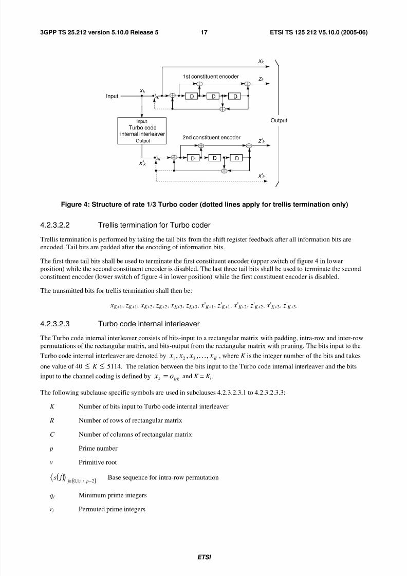
Figure 4: Structure of rate 1/3 Turbo coder (dotted lines apply for trellis termination only)
4.2.3.2.2 Trellis termination for Turbo coder
Trellis termination is performed by taking the tail bits from the shift register feedback after all information bits areencoded. Tail bits are padded after the encoding of information bits.
The first three tail bits shall be used to terminate the first constituent encoder (upper switch of figure 4 in lower
position) while the second constituent encoder is disabled. The last three tail bits shall be used to terminate the second
constituent encoder (lower switch of figure 4 in lower position) while the first constituent encoder is disabled.
The transmitted bits for trellis termination shall then be:
xK +1, zK +1, xK +2, zK +2, xK +3, zK +3, x'K +1, z'K +1, x'K +2, z'K +2, x'K +3, z'K +3.
4.2.3.2.3 Turbo code internal interleaver
The Turbo code internal interleaver consists of bits-input to a rectangular matrix with padding, intra-row and inter-row
permutations of the rectangular matrix, and bits-output from the rectangular matrix with pruning. The bits input to the
Turbo code internal interleaver are denoted byK x x x x ,,,, 321 K , where K is the integer number of the bits and takes
one value of 40 ≤ K ≤ 5114. The relation between the bits input to the Turbo code internal interleaver and the bits
input to the channel coding is defined byirk k o x = and K = K i.
The following subclause specific symbols are used in subclauses 4.2.3.2.3.1 to 4.2.3.2.3.3:
K Number of bits input to Turbo code internal interleaver
R Number of rows of rectangular matrix
C Number of columns of rectangular matrix
p Prime number
v Primitive root
( ){ }2,,1,0 −∈ p j
js Base sequence for intra-row permutation
qi Minimum prime integers
r i Permuted prime integers

7/31/2019 Ts_125212v051000p_release5_Multiplexing and Channel Coding (FDD)
http://slidepdf.com/reader/full/ts125212v051000prelease5multiplexing-and-channel-coding-fdd 19/74
ETSI
ETSI TS 125 212 V5.10.0 (2005-06)183GPP TS 25.212 version 5.10.0 Release 5
( ){ }1,,1,0 −∈ Ri
iT Inter-row permutation pattern
( ){ }1,,1,0 −∈ C j
ji
U Intra-row permutation pattern of i-th row
i Index of row number of rectangular matrix
j Index of column number of rectangularmatrix
k Index of bit sequence
4.2.3.2.3.1 Bits-input to rectangular matrix with padding
The bit sequence K x x x x ,,,, 321 K input to the Turbo code internal interleaver is written into the rectangular matrix as
follows.
(1) Determine the number of rows of the rectangular matrix, R, such that:
=
≤≤≤≤
≤≤
=
e)other valuany(if 20,
))530481(or)200160((if 10,
)15940(if 5,
K
K K
K
R .
The rows of rectangular matrix are numbered 0, 1, …, R - 1 from top to bottom.
(2) Determine the prime number to be used in the intra-permutation, p, and the number of columns of rectangularmatrix, C , such that:
if (481 ≤ K ≤ 530) then
p = 53 and C = p.
else
Find minimum prime number p from table 2 such that
( )1+×≤ p RK ,
and determine C such that
<×+
×≤<−×
−×≤−
=
K p Rif p
p RK p Rif p
p RK if p
C
1
)1(
)1(1
.
end if
The columns of rectangular matrix are numbered 0, 1, …, C - 1 from left to right.

7/31/2019 Ts_125212v051000p_release5_Multiplexing and Channel Coding (FDD)
http://slidepdf.com/reader/full/ts125212v051000prelease5multiplexing-and-channel-coding-fdd 20/74
ETSI
ETSI TS 125 212 V5.10.0 (2005-06)193GPP TS 25.212 version 5.10.0 Release 5
Table 2: List of prime number p and associated primitive root v
p v p v p v p v p v
7 3 47 5 101 2 157 5 223 3
11 2 53 2 103 5 163 2 227 2
13 2 59 2 107 2 167 5 229 6
17 3 61 2 109 6 173 2 233 319 2 67 2 113 3 179 2 239 7
23 5 71 7 127 3 181 2 241 7
29 2 73 5 131 2 191 19 251 6
31 3 79 3 137 3 193 5 257 3
37 2 83 2 139 2 197 2
41 6 89 3 149 2 199 3
43 3 97 5 151 6 211 2
(3) Write the input bit sequenceK x x x x ,,,, 321 K into the R × C rectangular matrix row by row starting with bit y1 in
column 0 of row 0:
×+−+−+−
+++
C R
C
C
C RC RC R
C C C
y
y
y
y y y
y y y
y y y
2
)3)1(()2)1(()1)1((
)3()2()1(
321
where yk = xk for k = 1, 2, …, K and if R× C > K , the dummy bits are padded such that 10or yk = for k = K + 1, K +
2, …, R× C . These dummy bits are pruned away from the output of the rectangular matrix after intra-row and inter-
row permutations.
4.2.3.2.3.2 Intra-row and inter-row permutations
After the bits-input to the R × C rectangular matrix, the intra-row and inter-row permutations for the R× C rectangularmatrix are performed stepwise by using the following algorithm with steps (1) – (6):
(1) Select a primitive root v from table 2 in section 4.2.3.2.3.1, which is indicated on the right side of the prime number
p.
(2) Construct the base sequence ( ){ }2,,1,0 −∈ p j
js for intra-row permutation as:
( ) ( )( ) p js js mod1−×= ν , j = 1, 2,…, ( p - 2), and s(0) = 1.
(3) Assign q0 = 1 to be the first prime integer in the sequence{ }1,,1,0 −∈ Riiq , and determine the prime integer qi in
the sequence{ }1,,1,0 −∈ Riiq to be a least prime integer such that g.c.d(qi, p - 1) = 1 , qi > 6, and qi > q(i - 1) for
each i = 1, 2, …, R – 1. Here g.c.d. is greatest common divisor.
(4) Permute the sequence{ }1,,1,0 −∈ Riiq to make the sequence
{ }1,,1,0 −∈ Riir such that
r T (i) = qi, i = 0, 1, …, R - 1,
where ( ){ }1,,1,0 −∈ Ri
iT is the inter-row permutation pattern defined as the one of the four kind of patterns, which
are shown in table 3, depending on the number of input bits K .

7/31/2019 Ts_125212v051000p_release5_Multiplexing and Channel Coding (FDD)
http://slidepdf.com/reader/full/ts125212v051000prelease5multiplexing-and-channel-coding-fdd 21/74
ETSI
ETSI TS 125 212 V5.10.0 (2005-06)203GPP TS 25.212 version 5.10.0 Release 5
Table 3: Inter-row permutation patterns for Turbo code internal interleaver
Number of input bitsK
Numberof rows R
Inter-row permutation patterns<T (0), T (1), …, T (R - 1)>
(40 ≤ K ≤ 159) 5 <4, 3, 2, 1, 0>
(160 ≤ K ≤ 200) or (481 ≤ K ≤ 530) 10 <9, 8, 7, 6, 5, 4, 3, 2, 1, 0>
(2281≤
K ≤
2480) or (3161≤
K ≤
3210) 20 <19, 9, 14, 4, 0, 2, 5, 7, 12, 18, 16, 13, 17, 15, 3, 1, 6, 11, 8, 10>K = any other value 20 <19, 9, 14, 4, 0, 2, 5, 7, 12, 18, 10, 8, 13, 17, 3, 1, 16, 6, 15, 11>
(5) Perform the i-th (i = 0, 1, …, R - 1) intra-row permutation as:
if (C = p) then
( ) ( ) ( )( )1mod −×= pr js jU ii , j = 0, 1, …, ( p - 2), and U i( p - 1) = 0,
where U i( j) is the original bit position of j-th permuted bit of i-th row.
end if
if (C = p + 1) then
( ) ( ) ( )( )1mod −×= pr js jU ii , j = 0, 1, …, ( p - 2). U i( p - 1) = 0, and U i( p) = p,
where U i( j) is the original bit position of j-th permuted bit of i-th row, and
if (K = R × C ) then
Exchange U R-1( p) with U R-1(0).
end if
end if
if (C = p - 1) then
( ) ( ) ( )( ) 11mod −−×= pr js jU ii , j = 0, 1, …, ( p - 2),
where U i( j) is the original bit position of j-th permuted bit of i-th row.
end if
(6) Perform the inter-row permutation for the rectangular matrix based on the pattern ( ){ }1,,1,0 −∈ Ri
iT ,
where T (i) is the original row position of the i-th permuted row.
4.2.3.2.3.3 Bits-output from rectangular matrix with pruning
After intra-row and inter-row permutations, the bits of the permuted rectangular matrix are denoted by y'k :
×
+−
+−
++
++
RC
RC
RC
R R R
R R
R R
y
y
y
y y y
y y y
y y y
'
'
'
'''
'''
'''
)2)1((
)1)1((
32
)22()2(2
)12()1(1

7/31/2019 Ts_125212v051000p_release5_Multiplexing and Channel Coding (FDD)
http://slidepdf.com/reader/full/ts125212v051000prelease5multiplexing-and-channel-coding-fdd 22/74
ETSI
ETSI TS 125 212 V5.10.0 (2005-06)213GPP TS 25.212 version 5.10.0 Release 5
The output of the Turbo code internal interleaver is the bit sequence read out column by column from the intra-row and
inter-row permuted R × C rectangular matrix starting with bit y'1 in row 0 of column 0 and ending with bit y'CR in row R
- 1 of column C - 1. The output is pruned by deleting dummy bits that were padded to the input of the rectangular
matrix before intra-row and inter row permutations, i.e. bits y'k that corresponds to bits yk with k > K are removed from
the output. The bits output from Turbo code internal interleaver are denoted by x'1, x'2, …, x'K , where x'1 corresponds to
the bit y'k with smallest index k after pruning, x'2 to the bit y'k with second smallest index k after pruning, and so on. The
number of bits output from Turbo code internal interleaver is K and the total number of pruned bits is:
R × C – K .
4.2.3.3 Concatenation of encoded blocks
After the channel coding for each code block, if C i is greater than 1, the encoded blocks are serially concatenated so that
the block with lowest index r is output first from the channel coding block, otherwise the encoded block is output from
channel coding block as it is. The bits output are denoted byiiE iii cccc ,,,, 321 K , where i is the TrCH number and
E i = C iY i. The output bits are defined by the following relations:
k iik yc 1= k = 1, 2 , … , Y i
)(,2, iY k iik yc−
= k = Y i + 1 , Y i + 2 , … , 2Y i
)2(,3, iY k iik yc−
= k = 2Y i + 1, 2Y i + 2 , … , 3Y i
))1((,, iii Y C k C iik yc−−
= k = (C i - 1)Y i + 1 , (C i - 1)Y i + 2 , … , C iY i
If no code blocks are input to the channel coding (C i = 0), no bits shall be output from the channel coding, i.e. E i = 0.
4.2.4 Radio frame size equalisationRadio frame size equalisation is padding the input bit sequence in order to ensure that the output can be segmented in F i
data segments of same size as described in subclause 4.2.7. Radio frame size equalisation is only performed in the UL.
The input bit sequence to the radio frame size equalisation is denoted byiiE iii cccc ,,,, 321 K , where i is TrCH number
and E i the number of bits. The output bit sequence is denoted byiiT iii t t t t ,,,, 321 K , where T i is the number of bits. The
output bit sequence is derived as follows:
- t ik = cik , for k = 1… E i; and
- t ik = {0, 1} for k= E i +1… T i, if E i < T i;
where
- Ti = F i * N i; and
- iii F E N = is the number of bits per segment after size equalisation.
4.2.5 1st interleaving
4.2.5.1 Void
4.2.5.2 1st interleaver operation
The 1st interleaving is a block interleaver with inter-column permutations. The input bit sequence to the block
interleaver is denoted byi X iiii x x x x ,3,2,1, ,,,, K , where i is TrCH number and X i the number of bits. Here X i is

7/31/2019 Ts_125212v051000p_release5_Multiplexing and Channel Coding (FDD)
http://slidepdf.com/reader/full/ts125212v051000prelease5multiplexing-and-channel-coding-fdd 23/74
ETSI
ETSI TS 125 212 V5.10.0 (2005-06)223GPP TS 25.212 version 5.10.0 Release 5
guaranteed to be an integer multiple of the number of radio frames in the TTI. The output bit sequence from the block
interleaver is derived as follows:
(1) Select the number of columns C1 from table 4 depending on the TTI. The columns are numbered 0, 1, …, C1 - 1
from left to right.
(2) Determine the number of rows of the matrix, R1 defined as
R1 = X i / C1.
The rows of the matrix are numbered 0, 1, …, R1 - 1 from top to bottom.
(3) Write the input bit sequence into the R1 × C1 matrix row by row starting with bit 1,i x in column 0 of row 0 and
ending with bit )C1R1(, ×i x in column C1 - 1 of row R1 - 1:
×
×
+×−+×−+×−
+++
)C1R1(,
)C12(,
C1,
)3C1)1R1((,)2C1)1R1((,)1C1)1R1((,
)3C1(,)2C1(,)1C1(,
3,2,1,
i
i
i
iii
iii
iii
x
x
x
x x x
x x x
x x x
M
K
KMMM
K
K
(4) Perform the inter-column permutation for the matrix based on the pattern ( ){ }1C1,,1,0C11P
−∈ j j shown in table
4, where P1C1 ( j) is the original column position of the j-th permuted column. After permutation of the columns,
the bits are denoted by yik :
×
+×−
+×−
××
+×+
+×+
)R1C1(,
)2R1)1C1((,
)1R1)1C1((,
)R13(,)R12(,R1,
)2R12(,)2R1(,2,
)1R12(,)1R1(,1,
i
i
i
iii
iii
iii
y
y
y
y y y
y y y
y y y
M
K
KMMM
K
K
(5) Read the output bit sequence )R1C1(,3,2,1, ,,,,×iiii y y y y K of the block interleaver column by column from the
inter-column permuted R1 × C1 matrix. Bit 1,i y corresponds to row 0 of column 0 and bit )C1R1(, ×i y
corresponds to row R1 - 1 of column C1 - 1.
Table 4 Inter-column permutation patterns for 1st interleaving
TTI Number of columns C1 Inter-column permutation patterns
<P1C1(0), P1C1(1), …, P1C1(C1-1)>
10 ms 1 <0>
20 ms 2 <0,1> 40 ms 4 <0,2,1,3>
80 ms 8 <0,4,2,6,1,5,3,7>
4.2.5.3 Relation between input and output of 1st interleaving in uplink
The bits input to the 1st interleaving are denoted byiT iiii t t t t ,3,2,1, ,,,, K , where i is the TrCH number and T i the number
of bits. Hence, xi,k = t i,k and Xi = T i.
The bits output from the 1st
interleaving are denoted byiT iiii d d d d ,3,2,1, ,,,, K , and di,k = yi,k .

7/31/2019 Ts_125212v051000p_release5_Multiplexing and Channel Coding (FDD)
http://slidepdf.com/reader/full/ts125212v051000prelease5multiplexing-and-channel-coding-fdd 24/74
ETSI
ETSI TS 125 212 V5.10.0 (2005-06)233GPP TS 25.212 version 5.10.0 Release 5
4.2.5.4 Relation between input and output of 1st interleaving in downlink
If fixed positions of the TrCHs in a radio frame is used then the bits input to the 1st
interleaving are denoted by
iiDiii hhhh ,,,, 321 K , where i is the TrCH number. Hence, xik = hik and Xi = Di.
If flexible positions of the TrCHs in a radio frame is used then the bits input to the 1st
interleaving are denoted by
iiGiii gggg ,,,, 321K
, where i is the TrCH number. Hence, xik = gik and Xi = Gi.
The bits output from the 1st
interleaving are denoted byiiQiii qqqq ,,,, 321 K , where i is the TrCH number and Qi is the
number of bits. Hence, qik = yik , Qi = F i H i if fixed positions are used, and Qi = Gi if flexible positions are used.
4.2.6 Radio frame segmentation
When the transmission time interval is longer than 10 ms, the input bit sequence is segmented and mapped onto
consecutive F i radio frames. Following rate matching in the DL and radio frame size equalisation in the UL the input bit
sequence length is guaranteed to be an integer multiple of F i.
The input bit sequence is denoted by iiX iii x x x x ,,,, 321K
where i is the TrCH number and X i is the number bits. The F i
output bit sequences per TTI are denoted byiiiii Y nininini y y y y ,3,2,1, ,,,, K where ni is the radio frame number in
current TTI and Y i is the number of bits per radio frame for TrCH i. The output sequences are defined as follows:
k ni i y , = ( )( ) k Y ni ii
x+⋅−1, , ni = 1…F i, k = 1…Y i
where
Y i = ( X i / F i) is the number of bits per segment.
The ni -th segment is mapped to the ni -th radio frame of the transmission time interval.
4.2.6.1 Relation between input and output of the radio frame segmentation block inuplink
The input bit sequence to the radio frame segmentation is denoted byiiT iii d d d d ,,,, 321 K , where i is the TrCH
number and T i the number of bits. Hence, xik = d ik and X i = T i.
The output bit sequence corresponding to radio frame ni is denoted byiiN iii eeee ,,,, 321 K , where i is the TrCH number
and N i is the number of bits. Hence, k nik i i ye ,, = and N i = Y i.
4.2.6.2 Relation between input and output of the radio frame segmentation block in
downlink
The bits input to the radio frame segmentation are denoted byiiQiii qqqq ,,,, 321 K , where i is the TrCH number and Qi
the number of bits. Hence, xik = qik and X i = Qi.
The output bit sequence corresponding to radio frame ni is denoted byiiV iii f f f f ,,,, 321 K , where i is the TrCH
number and V i is the number of bits. Hence, k nik i i y f ,, = and V i = Y i.
4.2.7 Rate matching
Rate matching means that bits on a transport channel are repeated or punctured. Higher layers assign a rate-matching
attribute for each transport channel. This attribute is semi-static and can only be changed through higher layer
signalling. The rate-matching attribute is used when the number of bits to be repeated or punctured is calculated.

7/31/2019 Ts_125212v051000p_release5_Multiplexing and Channel Coding (FDD)
http://slidepdf.com/reader/full/ts125212v051000prelease5multiplexing-and-channel-coding-fdd 25/74
ETSI
ETSI TS 125 212 V5.10.0 (2005-06)243GPP TS 25.212 version 5.10.0 Release 5
The number of bits on a transport channel can vary between different transmission time intervals. In the downlink the
transmission is interrupted if the number of bits is lower than maximum. When the number of bits between different
transmission time intervals in uplink is changed, bits are repeated or punctured to ensure that the total bit rate after
TrCH multiplexing is identical to the total channel bit rate of the allocated dedicated physical channels.
If no bits are input to the rate matching for all TrCHs within a CCTrCH, the rate matching shall output no bits for all
TrCHs within the CCTrCH and no uplink DPDCH will be selected in the case of uplink rate matching.
Notation used in subclause 4.2.7 and subclauses:
N i,j: For uplink: Number of bits in a radio frame before rate matching on TrCH i with transport format
combination j .
For downlink: An intermediate calculation variable (not an integer but a multiple of 1/8).
TTI
li N ,: Number of bits in a transmission time interval before rate matching on TrCH i with transport format l.
Used in downlink only.
ji N ,∆ : For uplink: If positive - number of bits that should be repeated in each radio frame on TrCH i with
transport format combination j.
If negative - number of bits that should be punctured in each radio frame on TrCH i with transport format
combination j.
For downlink : An intermediate calculation variable (not an integer but a multiple of 1/8).
TTI
li N ,∆ : If positive - number of bits to be repeated in each transmission time interval on TrCH i with transport
format l.
If negative - number of bits to be punctured in each transmission time interval on TrCH i with transport
format l.
Used in downlink only.
N TGL: Positive or null: number of bits in the radio frame corresponding to the gap for compressed mode for the
CCTrCH.
RM i: Semi-static rate matching attribute for transport channel i. RM i is provided by higher layers or takes a
value as indicated in section 4.2.13.
PL: Puncturing limit for uplink. This value limits the amount of puncturing that can be applied in order to
avoid multicode or to enable the use of a higher spreading factor. Signalled from higher layers. The
allowed puncturing in % is actually equal to (1-PL)*100.
N data,j: Total number of bits that are available for the CCTrCH in a radio frame with transport formatcombination j.
I: Number of TrCHs in the CCTrCH.
Z i,j: Intermediate calculation variable.
F i: Number of radio frames in the transmission time interval of TrCH i.
ni: Radio frame number in the transmission time interval of TrCH i (0 ≤ ni < F i).
q: Average puncturing or repetition distance (normalised to only show the remaining rate matching on top of
an integer number of repetitions). Used in uplink only.
P1F (ni): The column permutation function of the 1st interleaver, P1F (x) is the original position of column with
number x after permutation. P1 is defined on table 4 of section 4.2.5.2 (note that the P1 F is self-inverse).
Used for rate matching in uplink only.
S[n]: The shift of the puncturing or repetition pattern for radio frame ni when ( )iF nni
1P= . Used in uplink
only.

7/31/2019 Ts_125212v051000p_release5_Multiplexing and Channel Coding (FDD)
http://slidepdf.com/reader/full/ts125212v051000prelease5multiplexing-and-channel-coding-fdd 26/74
ETSI
ETSI TS 125 212 V5.10.0 (2005-06)253GPP TS 25.212 version 5.10.0 Release 5
TF i( j): Transport format of TrCH i for the transport format combination j.
TFS(i) The set of transport format indexes l for TrCH i.
TFCS The set of transport format combination indexes j.
eini Initial value of variable e in the rate matching pattern determination algorithm of subclause 4.2.7.5.
eplus Increment of variable e in the rate matching pattern determination algorithm of subclause4.2.7.5.
eminus Decrement of variable e in the rate matching pattern determination algorithm of subclause 4.2.7.5.
b: Indicates systematic and parity bits
b=1: Systematic bit. xk in subclause 4.2.3.2.1.
b=2: 1st parity bit (from the upper Turbo constituent encoder). zk in subcaluse 4.2.3.2.1.
b=3: 2nd
parity bit (from the lower Turbo constituent encoder). z'k in subclause 4.2.3.2.1.
The * (star) notation is used to replace an index x when the indexed variable X x does not depend on the index x. In the
left wing of an assignment the meaning is that " X * = Y " is equivalent to "for all x do X x = Y ". In the right wing of anassignment, the meaning is that "Y = X * " is equivalent to "take any x and do Y = X x".
The following relations, defined for all TFC j, are used when calculating the rate matching parameters:
0,0 = j Z
×
××
=
∑
∑
=
=
I
m jmm
jdata
i
m jmm
ji
N RM
N N RM Z
1,
,1
,
,
for all i = 1 … I (1)
ji ji ji ji N Z Z N ,,1,, −−=∆−
for all i = 1 … I
4.2.7.1 Determination of rate matching parameters in uplink
4.2.7.1.1 Determination of SF and number of PhCHs needed
In uplink, puncturing can be applied to match the CCTrCH bit rate to the PhCH bit rate. The bit rate of the PhCH(s) is
limited by the UE capability and restrictions imposed by UTRAN, through limitations on the PhCH spreading factor.
The maximum amount of puncturing that can be applied is 1-PL, PL is signalled from higher layers. The number of
available bits in the radio frames of one PhCH for all possible spreading factors is given in [2]. Denote these values by
N 256 , N 128 , N 64 , N 32 , N 16 , N 8 , and N 4 , where the index refers to the spreading factor. The possible number of bits available
to the CCTrCH on all PhCHs, N data, then are { N 256, N 128, N 64, N 32, N 16, N 8, N 4, 2× N 4, 3× N 4, 4× N 4, 5× N 4 , 6× N 4}.
For a RACH CCTrCH SET0 represents the set of N data values allowed by the UTRAN, as set by the minimum SF
provided by higher layers. SET0 may be a sub-set of { N 256, N 128, N 64, N 32 }. SET0 does not take into account the UE"s
capability.
For other CCTrCHs, SET0 denotes the set of N data values allowed by the UTRAN and supported by the UE, as part of
the UE"s capability. SET0 can be a subset of { N 256, N 128, N 64, N 32, N 16, N 8, N 4, 2× N 4, 3× N 4, 4× N 4, 5× N 4 , 6× N 4}. N data, j
for the transport format combination j is determined by executing the following algorithm:
SET1 = { N data in SET0 such that { } j x
I
x
xdata y I y
N RM N RM ,
11min ×−×
∑
=≤≤
is non negative }
If SET1 is not empty and the smallest element of SET1 requires just one PhCH then
N data,j = min SET1
7/31/2019 Ts_125212v051000p_release5_Multiplexing and Channel Coding (FDD)
http://slidepdf.com/reader/full/ts125212v051000prelease5multiplexing-and-channel-coding-fdd 27/74
ETSI
ETSI TS 125 212 V5.10.0 (2005-06)263GPP TS 25.212 version 5.10.0 Release 5
else
SET2 = { N data in SET0 such that { } j x
I
x
xdata y I y
N RM PL N RM ,
11min ××−×
∑
=≤≤
is non negative }
Sort SET2 in ascending order
N data = min SET2
While N data is not the max of SET2 and the follower of N data requires no additional PhCH do
N data = follower of N data in SET2
End while
N data, j = N data
End if
For a RACH CCTrCH, if N data,j is not part of the UE"s capability then the TFC j cannot be used.
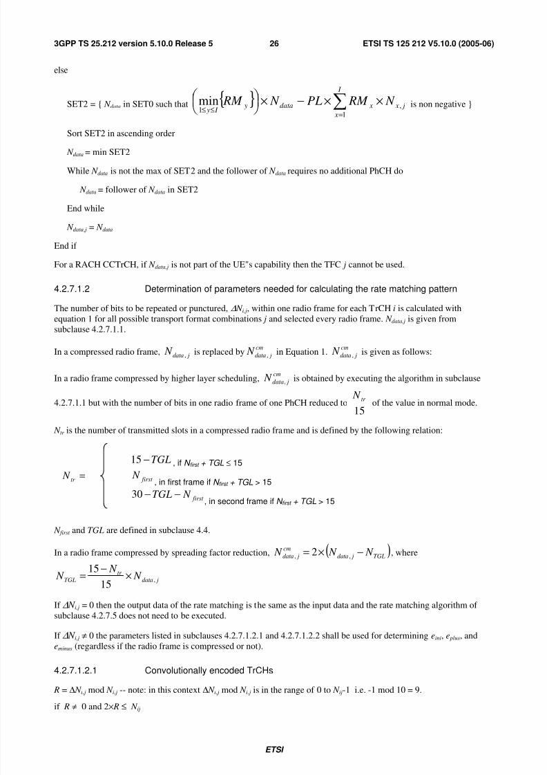
4.2.7.1.2 Determination of parameters needed for calculating the rate matching pattern
The number of bits to be repeated or punctured, ∆ N i,j, within one radio frame for each TrCH i is calculated with
equation 1 for all possible transport format combinations j and selected every radio frame. N data,j is given from
subclause 4.2.7.1.1.
In a compressed radio frame, jdata N , is replaced bycm
jdata N , in Equation 1.cm
jdata N , is given as follows:
In a radio frame compressed by higher layer scheduling,cm
jdata N , is obtained by executing the algorithm in subclause
4.2.7.1.1 but with the number of bits in one radio frame of one PhCH reduced to 15
tr N
of the value in normal mode.
N tr is the number of transmitted slots in a compressed radio frame and is defined by the following relation:
=tr N
TGL−15 , if N first + TGL ≤ 15
first N
, in first frame if N first + TGL > 15
first N TGL −−30, in second frame if N first + TGL > 15
N first and TGL are defined in subclause 4.4.
In a radio frame compressed by spreading factor reduction, ( )TGL jdata
cm
jdata N N N −×= ,, 2 , where
jdatatr
TGL N N
N ,15
15×
−=
If ∆ N i,j = 0 then the output data of the rate matching is the same as the input data and the rate matching algorithm of
subclause 4.2.7.5 does not need to be executed.
If ∆ N i,j ≠ 0 the parameters listed in subclauses 4.2.7.1.2.1 and 4.2.7.1.2.2 shall be used for determining eini, e plus, and
eminus (regardless if the radio frame is compressed or not).
4.2.7.1.2.1 Convolutionally encoded TrCHs
R = ∆ N i, j mod N i, j -- note: in this context ∆ N i, j mod N i, j is in the range of 0 to N ij-1 i.e. -1 mod 10 = 9.
if R ≠ 0 and 2× R ≤ N ij

7/31/2019 Ts_125212v051000p_release5_Multiplexing and Channel Coding (FDD)
http://slidepdf.com/reader/full/ts125212v051000prelease5multiplexing-and-channel-coding-fdd 28/74
ETSI
ETSI TS 125 212 V5.10.0 (2005-06)273GPP TS 25.212 version 5.10.0 Release 5
then q = N i,j / R
else
q = N i, j / ( R - N i, j)
endif
-- note: q is a signed quantity.
if q is even
then q' = q + gcd( q , F i)/ F i -- where gcd ( q , F i) means greatest common divisor of q and F i
-- note that q' is not an integer, but a multiple of 1/8
else
q' = q
endif
for x = 0 to F i - 1
S[ x×q' mod F i] = ( x×q' div F i)
end for
∆ N i = ∆ N i, j
a = 2
For each radio frame, the rate-matching pattern is calculated with the algorithm in subclause 4.2.7.5, where :
X i = N i, j., and
eini = (a×
S[P1Fi(ni)]×
|∆ N i | + 1) mod (a
⋅ N ij).
eplus = a× N i, j
eminus = a×|∆ N i|
puncturing for ∆ N <0, repetition otherwise.
4.2.7.1.2.2 Turbo encoded TrCHs
If repetition is to be performed on turbo encoded TrCHs, i.e. ∆ N i,j >0, the parameters in subclause 4.2.7.1.2.1 are used.
If puncturing is to be performed, the parameters below shall be used. Index b is used to indicate systematic (b=1),
1st parity (b=2), and 2nd parity bit (b=3).
a=2 when b=2
a=1 when b=3
=∆
=∆=∆
3 ,2
2 ,2
,
,
b N
b N N
ji
ji
i
If i N ∆ is calculated as 0 for b=2 or b=3, then the following procedure and the rate matching algorithm of
subclause 4.2.7.5 don't need to be performed for the corresponding parity bit stream.
Xi = Ni,j /3 ,
q = Xi /|∆Ni|
if(q ≤ 2)

7/31/2019 Ts_125212v051000p_release5_Multiplexing and Channel Coding (FDD)
http://slidepdf.com/reader/full/ts125212v051000prelease5multiplexing-and-channel-coding-fdd 29/74
ETSI
ETSI TS 125 212 V5.10.0 (2005-06)283GPP TS 25.212 version 5.10.0 Release 5
for r=0 to F i-1
S[(3×r +b-1) mod F I ] = r mod 2;
end for
else
if q is even
then q' = q – gcd( q , F i) / F i -- where gcd ( q , F i) means greatest common divisor of q and F i
-- note that q' is not an integer, but a multiple of 1/8
else q' = q
endif
for x=0 to F i -1
r = x×q' mod F i;
S[(3×r+b-1) mod F i] = x×q' div F i;
endfor
endif
For each radio frame, the rate-matching pattern is calculated with the algorithm in subclause 4.2.7.5, where:
X i is as above:
eini = (a×S[P1Fi(ni)] ×|∆Ni| + Xi) mod (a× X i), if eini =0 then eini = a× X i
eplus = a× X i
eminus = a× ∆
N i
4.2.7.2 Determination of rate matching parameters in downlink
For downlink channels, N data,j does not depend on the transport format combination j. N data,* is given by the
channelization code(s) assigned by higher layers.
Denote the number of physical channels used for the CCTrCH by P. N data,* is the number of bits available to the
CCTrCH in one radio frame and defined as N data,*=P×15×( N data1+ N data2), where N data1 and N data2 are defined in [2]. Note
that contrary to the uplink, the same rate matching patterns are used in TTIs containing no compressed radio frames and
in TTIs containing radio frames compressed by spreading factor reduction or higher layer scheduling.
4.2.7.2.1 Determination of rate matching parameters for fixed positions of TrCHs
4.2.7.2.1.1 Calculation of ∆N i ,max for normal mode and compressed mode by spreading factorreduction
First an intermediate calculation variable ,*i N is calculated for all transport channels i by the following formula:
( )×=
∈
TTI
liiTFSl
i
i N F
N ,,* max1
In order to compute theTTI
li N ,∆ parameters for all TrCH i and all TF l, we first compute an intermediate parameter
∆ N i,max by the following formula, where,*i
N ∆ is derived from,*i
N by the formula given at subclause 4.2.7:
,*, iimaxi N F N ∆×=∆

7/31/2019 Ts_125212v051000p_release5_Multiplexing and Channel Coding (FDD)
http://slidepdf.com/reader/full/ts125212v051000prelease5multiplexing-and-channel-coding-fdd 30/74
ETSI
ETSI TS 125 212 V5.10.0 (2005-06)293GPP TS 25.212 version 5.10.0 Release 5
If 0, =∆ maxi N then, for TrCH i, the output data of the rate matching is the same as the input data and the rate
matching algorithm of subclause 4.2.7.5 does not need to be executed. In this case we have :
( ) 0, =∆∈∀TTI
li N iTFSl
If 0, ≠∆ maxi N the parameters listed in subclauses 4.2.7.2.1.3 and 4.2.7.2.1.4 shall be used for determining eini, e plus,
and eminus , andTTI
li N ,∆ .
4.2.7.2.1.2 Void
4.2.7.2.1.3 Determination of rate matching parameters for convolutionally encoded TrCHs
maxii N N ,∆=∆
a=2
( )TTI il
iTFSlmax N N
∈= max
For each transmission time interval of TrCH i with TF l, the rate-matching pattern is calculated with the algorithm in
subclause 4.2.7.5. The following parameters are used as input:
TTI
ili N X =
=inie 1
max plus N ae ×=
ius N ae ∆×=min
Puncturing if 0<∆ i N , repetition otherwise. The values of TTI
li N ,∆ may be computed by counting repetitions or
puncturing when the algorithm of subclause 4.2.7.5 is run. The resulting values of TTI
li N ,∆ can be represented with
following expression.
)sgn(, i
max
iiTTI
li N N
X N N ∆×
×∆=∆
4.2.7.2.1.4 Determination of rate matching parameters for Turbo encoded TrCHs
If repetition is to be performed on turbo encoded TrCHs, i.e. 0, >∆ maxi N , the parameters in subclause 4.2.7.2.1.3 are
used.
If puncturing is to be performed, the parameters below shall be used. Index b is used to indicate systematic (b=1),
1st
parity (b=2), and 2nd
parity bit (b=3).
a=2 when b=2
a=1 when b=3
The bits indicated by b=1 shall not be punctured.
=∆=∆=∆
3for,22for,2
,
,
b N b N N
maxi
maxib
i

7/31/2019 Ts_125212v051000p_release5_Multiplexing and Channel Coding (FDD)
http://slidepdf.com/reader/full/ts125212v051000prelease5multiplexing-and-channel-coding-fdd 31/74
ETSI
ETSI TS 125 212 V5.10.0 (2005-06)303GPP TS 25.212 version 5.10.0 Release 5
( ))3 / (max TTI
iliTFSl
max N N ∈
=
For each transmission time interval of TrCH i with TF l, the rate-matching pattern is calculated with the algorithm in
subcaluse 4.2.7.5. The following parameters are used as input:
3 / TTI
ili N X =
maxini N e =
max plus N ae ×=
b
ius N ae ∆×=min
The values of TTI
li N ,∆ may be computed by counting puncturing when the algorithm of subclause 4.2.7.5 is run. The
resulting values of TTI
li N ,∆ can be represented with following expression.
×∆−
+
×∆−=∆
max
ii
max
iiTTI
li N
X N
N
X N N
32
, 5.0
In the above equation, the first term of the right hand side represents the amount of puncturing for b=2 and the second
term represents the amount of puncturing for b=3.
4.2.7.2.2 Determination of rate matching parameters for flexible positions of TrCHs
4.2.7.2.2.1 Calculations for normal mode, compressed mode by higher layer scheduling, andcompressed mode by spreading factor reduction
First an intermediate calculation variable ij N is calculated for all transport channels i and all transport format
combinations j by the following formula:
( )TTI
jTF i
i
ji i N
F N ,,
1×=
Then rate matching ratios RF i are calculated for each the transport channel i in order to minimise the number of DTX
bits when the bit rate of the CCTrCH is maximum. The RF i ratios are defined by the following formula:
( )i I i
i
jiiTFCS j
data
i RM
N RM
N RF ×
×
=
∑=
=∈
1
,
,*
max
The computation of TTI
li N ,∆ parameters is then performed in two phases. In a first phase, tentative temporary values of
TTI
li N ,∆ are computed, and in the second phase they are checked and corrected. The first phase, by use of the RF i ratios,
ensures that the number of DTX indication bits inserted is minimum when the CCTrCH bit rate is maximum, but it does
not ensure that the maximum CCTrCH bit rate is not greater than N data,*. per 10ms. The latter condition is ensured
through the checking and possible corrections carried out in the second phase.
At the end of the second phase, the latest value of TTI
li N ,∆ is the definitive value.
The first phase defines the tentative temporary TTI li N ,∆ for all transport channel i and any of its transport format l by use
of the following formula:

7/31/2019 Ts_125212v051000p_release5_Multiplexing and Channel Coding (FDD)
http://slidepdf.com/reader/full/ts125212v051000prelease5multiplexing-and-channel-coding-fdd 32/74
ETSI
ETSI TS 125 212 V5.10.0 (2005-06)313GPP TS 25.212 version 5.10.0 Release 5
( ) N
N RM F
N RM N F N
F
N RF F N
TTI
li I
i jiiTFCS ji
TTI
liidata
i
TTI
li
i
TTI
lii
i
TTI
li ,
1,
,,*
,
,
,
max
−
××
×××=−
⋅
××=∆
∑=
∈
The second phase is defined by the following algorithm:
for all j in TFCS in ascending order of TFCI do -- for all TFC
( ) ( )∑
=
=
∆+=
I i
i i
TTI
jTF i
TTI
jTF i
F
N N D ii
1
,, -- CCTrCH bit rate (bits per 10ms) for TFC j
if ,*data N D > then
for i = 1 to I do -- for all TrCH
jii N F N ,∆×=∆ -- ji N ,∆ is derived from ji N , by the formula given at subclause 4.2.7.
if ( ) N N TTI
jTF i i∆>∆ , then
( ) N N TTI
jTF i i∆=∆ ,
end-if
end-for
end-if
end-for
If 0, =∆ TTI li N then, for TrCH i at TF l, the output data of the rate matching is the same as the input data and the rate
matching algorithm of subclause 4.2.7.5 does not need to be executed.
If 0, ≠∆TTI
li N the parameters listed in subclauses 4.2.7.2.2.2 and 4.2.7.2.2.3 shall be used for determining eini, e plus, and
eminus.
4.2.7.2.2.2 Determination of rate matching parameters for convolutionally encoded TrCHs
TTI
ili N N ∆=∆
a=2
For each transmission time interval of TrCH i with TF l, the rate-matching pattern is calculated with the algorithm in
subclause 4.2.7.5. The following parameters are used as input:
TTI
ili N X =
=inie 1
TTI
il plus N ae ×=
ius N ae ∆×=min
puncturing for 0<∆ i N , repetition otherwise.

7/31/2019 Ts_125212v051000p_release5_Multiplexing and Channel Coding (FDD)
http://slidepdf.com/reader/full/ts125212v051000prelease5multiplexing-and-channel-coding-fdd 33/74
ETSI
ETSI TS 125 212 V5.10.0 (2005-06)323GPP TS 25.212 version 5.10.0 Release 5
4.2.7.2.2.3 Determination of rate matching parameters for Turbo encoded TrCHs
If repetition is to be performed on turbo encoded TrCHs, i.e. 0>∆TTI
il N , the parameters in subclause 4.2.7.2.2.2 are
used.
If puncturing is to be performed, the parameters below shall be used. Index b is used to indicate systematic (b=1), 1st
parity (b=2), and 2nd
parity bit (b=3).
a=2 when b=2
a=1 when b=3
The bits indicated by b=1 shall not be punctured.
=∆
=∆=∆
3 ,2
2 ,2
b N
b N N
TTI
il
TTI
il
i
For each transmission time interval of TrCH i with TF l, the rate-matching pattern is calculated with the algorithm in
subclause 4.2.7.5. The following parameters are used as input:
3 / TTI
ili N X = ,
iini X e = ,
i plus X ae ×=
ius N ae ∆×=min
4.2.7.3 Bit separation and collection in uplink
The systematic bits of turbo encoded TrCHs shall not be punctured, the other bits may be punctured. The systematic
bits, first parity bits, and second parity bits in the bit sequence input to the rate matching block are therefore separated
into three sequences.
The first sequence contains:
- All of the systematic bits that are from turbo encoded TrCHs.
- From 0 to 2 first and/or second parity bits that are from turbo encoded TrCHs. These bits come into the first
sequence when the total number of bits in a block after radio frame segmentation is not a multiple of three.
- Some of the systematic, first parity and second parity bits that are for trellis termination.
The second sequence contains:
- All of the first parity bits that are from turbo encoded TrCHs, except those that go into the first sequence whenthe total number of bits is not a multiple of three.
- Some of the systematic, first parity and second parity bits that are for trellis termination.
The third sequence contains:
- All of the second parity bits that are from turbo encoded TrCHs, except those that go into the first sequence
when the total number of bits is not a multiple of three.
- Some of the systematic, first parity and second parity bits that are for trellis termination.
The second and third sequences shall be of equal length, whereas the first sequence can contain from 0 to 2 more bits.
Puncturing is applied only to the second and third sequences.The bit separation function is transparent forconvolutionally encoded TrCHs and for turbo encoded TrCHs with repetition. The bit separation and bit collection are
illustrated in figures 5 and 6.

7/31/2019 Ts_125212v051000p_release5_Multiplexing and Channel Coding (FDD)
http://slidepdf.com/reader/full/ts125212v051000prelease5multiplexing-and-channel-coding-fdd 34/74
ETSI
ETSI TS 125 212 V5.10.0 (2005-06)333GPP TS 25.212 version 5.10.0 Release 5
Radio framesegmentation
Bit separationRate matching
algorithm
Bitcollection
TrCHMultiplexing
Rate matching
eik x2ik
x1ik
x3ik
2ik
3ik
1ik
f ik
Rate matching
algorithm
Figure 5: Puncturing of turbo encoded TrCHs in uplink
Radio frame
segmentationBit separation
Rate matching
algorithm
Bit
collection
TrCH
Multiplexing
Rate matching
eik x1ik 1ik ik
Figure 6: Rate matching for convolutionally encoded TrCHs
and for turbo encoded TrCHs with repetition in uplink
The bit separation is dependent on the 1st
interleaving and offsets are used to define the separation for different TTIs. b
indicates the three sequences defined in this section, with b=1 indicating the first sequence, b = 2 the second one, and b
= 3 the third one. The offsets α b for these sequences are listed in table 5.
Table 5: TTI dependent offset needed for bit separation
TTI (ms) α αα α 1 α αα α 2 α αα α 3
10, 40 0 1 2
20, 80 0 2 1
The bit separation is different for different radio frames in the TTI. A second offset is therefore needed. The radio framenumber for TrCH i is denoted by ni. and the offset by
in β .
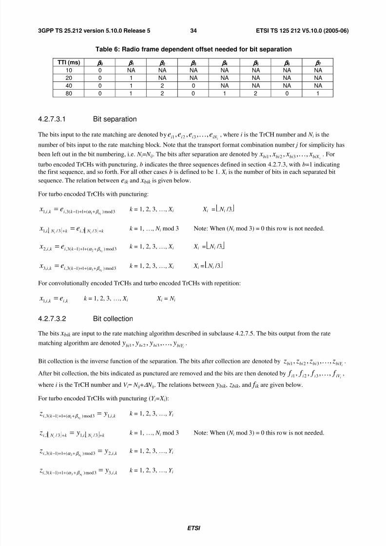
7/31/2019 Ts_125212v051000p_release5_Multiplexing and Channel Coding (FDD)
http://slidepdf.com/reader/full/ts125212v051000prelease5multiplexing-and-channel-coding-fdd 35/74
ETSI
ETSI TS 125 212 V5.10.0 (2005-06)343GPP TS 25.212 version 5.10.0 Release 5
Table 6: Radio frame dependent offset needed for bit separation
TTI (ms) β ββ β 0 β ββ β 1 β ββ β 2 β ββ β 3 β ββ β 4 β ββ β 5 β ββ β 6 β ββ β 7
10 0 NA NA NA NA NA NA NA
20 0 1 NA NA NA NA NA NA
40 0 1 2 0 NA NA NA NA
80 0 1 2 0 1 2 0 1
4.2.7.3.1 Bit separation
The bits input to the rate matching are denoted byiiN iii eeee ,,,, 321 K , where i is the TrCH number and N i is the
number of bits input to the rate matching block. Note that the transport format combination number j for simplicity has
been left out in the bit numbering, i.e. N i= N ij. The bits after separation are denoted byibiX bibibi x x x x ,,,, 321 K . For
turbo encoded TrCHs with puncturing, b indicates the three sequences defined in section 4.2.7.3, with b=1 indicating
the first sequence, and so forth. For all other cases b is defined to be 1. X i is the number of bits in each separated bit
sequence. The relation between eik and xbik is given below.
For turbo encoded TrCHs with puncturing:
3mod)(1)1(3,,,1 1 ink ik i e x β α +++−= k = 1, 2, 3, …, X i X i = N i /3
k N ik N i iie x
++= 3 / 3,3 / ,,1 k = 1, …, N i mod 3 Note: When ( N i mod 3) = 0 this row is not needed.
3mod)(1)1(3,,,2 2 ink ik i e x β α +++−= k = 1, 2, 3, …, X i X i = N i /3
3mod)(1)1(3,,,3 3 ink ik i e x β α +++−= k = 1, 2, 3, …, X i X i = N i /3
For convolutionally encoded TrCHs and turbo encoded TrCHs with repetition:
k ik i e x ,,,1 = k = 1, 2, 3, …, X i X i = N i
4.2.7.3.2 Bit collection
The bits xbik are input to the rate matching algorithm described in subclause 4.2.7.5. The bits output from the rate
matching algorithm are denotedibiY bibibi y y y y ,,,, 321 K .
Bit collection is the inverse function of the separation. The bits after collection are denoted byibiY bibibi z z z z ,,,, 321 K .
After bit collection, the bits indicated as punctured are removed and the bits are then denoted byiiV iii f f f f ,,,, 321 K ,
where i is the TrCH number and V i= N ij+∆ N ij. The relations between ybik , zbik , and f ik are given below.
For turbo encoded TrCHs with puncturing (Y i=X i):
k ik i y zin ,,13mod)(1)1(3, 1
=+++− β α k = 1, 2, 3, …, Y i
k N ik N i ii y z
++= 3 / ,,13 / 3, k = 1, …, N i mod 3 Note: When ( N i mod 3) = 0 this row is not needed.
k ik i y zin ,,23mod)(1)1(3, 2
=+++− β α k = 1, 2, 3, …, Y i
k ik i y zin ,,33mod)(1)1(3, 3
=+++− β α k = 1, 2, 3, …, Y i

7/31/2019 Ts_125212v051000p_release5_Multiplexing and Channel Coding (FDD)
http://slidepdf.com/reader/full/ts125212v051000prelease5multiplexing-and-channel-coding-fdd 36/74
ETSI
ETSI TS 125 212 V5.10.0 (2005-06)353GPP TS 25.212 version 5.10.0 Release 5
After the bit collection, bits zi,k with value δ , where δ∉{0, 1}, are removed from the bit sequence. Bit f i,1 corresponds to
the bit zi,k with smallest index k after puncturing, bit f i,2 corresponds to the bit zi,k with second smallest index k after
puncturing, and so on.
For convolutionally encoded TrCHs and turbo encoded TrCHs with repetition:
k ik i y z ,,1, = k = 1, 2, 3, …, Y i
When repetition is used, f i,k = zi,k and Y i=V i.
When puncturing is used, Y i= X i and bits zi,k with value δ , where δ∉{0, 1}, are removed from the bit sequence. Bit f i,1
corresponds to the bit zi,k with smallest index k after puncturing, bit f i,2 corresponds to the bit zi,k with second smallest
index k after puncturing, and so on.
4.2.7.4 Bit separation and collection in downlink
The systematic bits of turbo encoded TrCHs shall not be punctured, the other bits may be punctured.
The systematic bits, first parity bits and second parity bits in the bit sequence input to the rate matching block aretherefore separated into three sequences of equal lengths.
The first sequence contains :
- All of the systematic bits that are from turbo encoded TrCHs.
- Some of the systematic, first parity and second parity bits that are for trellis termination.
The second sequence contains:
- All of the first parity bits that are from turbo encoded TrCHs.
- Some of the systematic, first parity and second parity bits that are for trellis termination.
The third sequence contains:
- All of the second parity bits that are from turbo encoded TrCHs.
- Some of the systematic, first parity and second parity bits that are for trellis termination.
Puncturing is applied only to the second and third sequences.
The bit separation function is transparent for convolutionally encoded TrCHs and for turbo encoded TrCHs with
repetition. The bit separation and bit collection are illustrated in figures 7 and 8.
Channel
coding
Bit separation
Rate matching
algorithm
Bit
collection
1st insertion of
DTX
indication
Rate matching
cik x2ik
x1ik
x3ik
2ik
3ik
1ik
gik
Rate matching
algorithm
Figure 7: Puncturing of turbo encoded TrCHs in downlink

7/31/2019 Ts_125212v051000p_release5_Multiplexing and Channel Coding (FDD)
http://slidepdf.com/reader/full/ts125212v051000prelease5multiplexing-and-channel-coding-fdd 37/74
ETSI
ETSI TS 125 212 V5.10.0 (2005-06)363GPP TS 25.212 version 5.10.0 Release 5
Channelcoding Bit separation
Rate matching
algorithm
Bitcollection 1
st
insertion of DTX
indication
Rate matching
x1ik 1ik cik gik
Figure 8: Rate matching for convolutionally encoded TrCHsand for turbo encoded TrCHs with repetition in downlink
4.2.7.4.1 Bit separation
The bits input to the rate matching are denoted byiiE iii cccc ,,,, 321 K , where i is the TrCH number and E i is the
number of bits input to the rate matching block. Note that E i is a multiple of 3 for turbo encoded TrCHs and that the
transport format l for simplicity has been left out in the bit numbering, i.e. E i=TTI
il N . The bits after separation are
denoted byibiX bibibi x x x x ,,,, 321 K . For turbo encoded TrCHs with puncturing, b indicates the three sequences defined
in section 4.2.7.4, with b=1 indicating the first sequence, and so forth. For all other cases b is defined to be 1. X i is the
number of bits in each separated bit sequence. The relation between cik and xbik is given below.
For turbo encoded TrCHs with puncturing:
1)1(3,,,1 +−= k ik i c x k = 1, 2, 3, …, X i X i = E i /3
2)1(3,,,2 +−= k ik i c x k = 1, 2, 3, …, X i X i = E i /3
3)1(3,,,3 +−= k ik i c x k = 1, 2, 3, …, X i X i = E i /3
For convolutionally encoded TrCHs and turbo encoded TrCHs with repetition:
k ik i c x ,,,1 = k = 1, 2, 3, …, X i X i = E i
4.2.7.4.2 Bit collection
The bits xbik are input to the rate matching algorithm described in subclause 4.2.7.5. The bits output from the rate
matching algorithm are denotedibiY bibibi y y y y ,,,, 321 K .
Bit collection is the inverse function of the separation. The bits after collection are denoted byibiY bibibi z z z z ,,,, 321 K .
After bit collection, the bits indicated as punctured are removed and the bits are then denoted byiiGiii gggg ,,,, 321 K ,
where i is the TrCH number and Gi=TTI
il N +TTI
il N ∆ . The relations between ybik , zbik , and gik are given below.
For turbo encoded TrCHs with puncturing (Y i=X i):
k ik i y z ,,11)1(3, =+−
k = 1, 2, 3, …, Y i

7/31/2019 Ts_125212v051000p_release5_Multiplexing and Channel Coding (FDD)
http://slidepdf.com/reader/full/ts125212v051000prelease5multiplexing-and-channel-coding-fdd 38/74
ETSI
ETSI TS 125 212 V5.10.0 (2005-06)373GPP TS 25.212 version 5.10.0 Release 5
k ik i y z ,,22)1(3, =+−
k = 1, 2, 3, …, Y i
k ik i y z ,,33)1(3, =+−
k = 1, 2, 3, …, Y i
After the bit collection, bits zi,k with value δ , where δ∉{0, 1}, are removed from the bit sequence. Bit gi,1 corresponds
to the bit zi,k with smallest index k after puncturing, bit gi,2 corresponds to the bit zi,k with second smallest index k afterpuncturing, and so on.
For convolutionally encoded TrCHs and turbo encoded TrCHs with repetition:
k ik i y z ,,1, = k = 1, 2, 3, …, Y i
When repetition is used, gi,k = zi,k and Y i=Gi.
When puncturing is used, Y i= X i and bits zi,k with value δ , where δ∉{0, 1}, are removed from the bit sequence. Bit gi,1
corresponds to the bit zi,k with smallest index k after puncturing, bit gi,2 corresponds to the bit zi,k with second smallest
index k after puncturing, and so on.
4.2.7.5 Rate matching pattern determination
Denote the bits before rate matching by:
iiX iii x x x x ,,,, 321 K , where i is the TrCH number and the sequence is defined in 4.2.7.3 for uplink or in 4.2.7.4 for
downlink. Parameters X i, eini, eplus, and eminus are given in 4.2.7.1 for uplink or in 4.2.7.2 for downlink.
The rate matching rule is as follows:
if puncturing is to be performed
e = eini -- initial error between current and desired puncturing ratio
m = 1 -- index of current bit
do while m <= Xi
e = e – eminus -- update error
if e <= 0 then -- check if bit number m should be punctured
set bit xi,m to δ where δ∉{0, 1}
e = e + eplus -- update error
end if
m = m + 1 -- next bit
end do
else
e = eini -- initial error between current and desired puncturing ratio
m = 1 -- index of current bit
do while m <= Xi
e = e – eminus -- update error
do while e <= 0 -- check if bit number m should be repeated
repeat bit xi,m
e = e + e plus -- update error

7/31/2019 Ts_125212v051000p_release5_Multiplexing and Channel Coding (FDD)
http://slidepdf.com/reader/full/ts125212v051000prelease5multiplexing-and-channel-coding-fdd 39/74
ETSI
ETSI TS 125 212 V5.10.0 (2005-06)383GPP TS 25.212 version 5.10.0 Release 5
end do
m = m + 1 -- next bit
end do
end if
A repeated bit is placed directly after the original one.
4.2.8 TrCH multiplexing
Every 10 ms, one radio frame from each TrCH is delivered to the TrCH multiplexing. These radio frames are serially
multiplexed into a coded composite transport channel (CCTrCH).
The bits input to the TrCH multiplexing are denoted byiiV iii f f f f ,,,, 321 K , where i is the TrCH number and V i is the
number of bits in the radio frame of TrCH i. The number of TrCHs is denoted by I . The bits output from TrCH
multiplexing are denoted by Sssss ,,,, 321 K , where S is the number of bits, i.e. ∑=i
iV S . The TrCH multiplexing is
defined by the following relations:
k k f s 1= k = 1, 2 , … , V 1
)(,2 1V k k f s−
= k = V 1+1 , V 1+2 , … , V 1+V 2
))((,3 21 V V k k f s+−
= k = (V 1+V 2)+1 , (V 1+V 2)+2 , … , (V 1+V 2)+V 3
))((, 121 −+++−=
I V V V k I k f s k = (V 1+V 2+…+V I -1)+1 , (V 1+V 2+…+V I -1)+2 , … , (V 1+V 2+…+V I -1)+V I
4.2.9 Insertion of discontinuous transmission (DTX) indication bits
In the downlink, DTX is used to fill up the radio frame with bits. The insertion point of DTX indication bits depends on
whether fixed or flexible positions of the TrCHs in the radio frame are used. It is up to the UTRAN to decide for each
CCTrCH whether fixed or flexible positions are used during the connection. DTX indication bits only indicate when the
transmission should be turned off, they are not transmitted.
4.2.9.1 1st insertion of DTX indication bits
This step of inserting DTX indication bits is used only if the positions of the TrCHs in the radio frame are fixed. With
fixed position scheme a fixed number of bits is reserved for each TrCH in the radio frame.
The bits from rate matching are denoted byiiGiii gggg ,,,, 321 K, where Gi is the number of bits in one TTI of TrCH i.
Denote the number of bits in one radio frame of TrCH i by H i. Denote Di the number of bits output of the first DTXinsertion block.
In TTIs containing no compressed frames or frames compressed by spreading factor reduction, H i is constant and
corresponds to the maximum number of bits from TrCH i in one radio frame for any transport format of TrCH i and Di
= F i × H i.
The bits output from the DTX insertion are denoted by h i1 , h i2 , h i3 , … , h iDi Note that these bits are three valued. They
are defined by the following relations:
ik ik gh = k = 1, 2, 3, …, Gi
δ =ik h k = Gi+1 , Gi+2 , Gi+3 , … , Di

7/31/2019 Ts_125212v051000p_release5_Multiplexing and Channel Coding (FDD)
http://slidepdf.com/reader/full/ts125212v051000prelease5multiplexing-and-channel-coding-fdd 40/74
ETSI
ETSI TS 125 212 V5.10.0 (2005-06)393GPP TS 25.212 version 5.10.0 Release 5
where DTX indication bits are denoted by δ . Here gik ∈{0, 1} and δ ∉{0, 1}.
4.2.9.2 2nd insertion of DTX indication bits
The DTX indication bits inserted in this step shall be placed at the end of the radio frame. Note that the DTX will be
distributed over all slots after 2nd interleaving.
The bits input to the DTX insertion block are denoted bySssss ,,,, 321 K ,where S is the number of bits from TrCH
multiplexing. The number of PhCHs is denoted by P and the number of bits in one radio frame, including DTX
indication bits, for each PhCH by R..
In non-compressed frames, ( )21
,*15 datadata
data N N
P
N R +×== , where N data1 and N data2 are defined in [2].
For compressed frames, N' data,* is defined as )(15 '
2
'
1
'
,* datadatadata N N P N +××= .'
1data N and'
2data N are the number
of bits in the data fields of the slot format used for the current compressed frame, i.e. slot format A or B as defined in
[2] corresponding to the spreading factor and the number of transmitted slots in use.
In frames compressed by higher layer scheduling, additional DTX with respect to normal mode shall be inserted if the
transmission time reduction does not exactly create a transmission gap of the desired TGL.
The number of bits available to the CCTrCH in one radio frame compressed by spreading factor reduction or by higher
layer scheduling is denoted bycm
data N ,* andP
N R
cm
data ,*= .
For frames compressed by spreading factor reduction2
' ,*
,*
datacm
data
N N = .
For frames compressed by higher layer scheduling the exact value of cm
data N ,* is dependent on the TGL which is
signalled from higher layers. It can be calculated asTGLdata
cm
data N N N −='
,*,* .
N TGL is the number of bits that are located within the transmission gap and defined as:
=TGL N
'
,*15
data N TGL
×, if N first + TGL ≤ 15
'
,*15
15data
first N
N ×
−
, in first frame if N first + TGL > 15
' ,*15
)15(data first N
N TGL×
−−
, in second frame if N first + TGL > 15
N first and TGL are defined in subclause 4.4.
The bits output from the DTX insertion block are denoted by )(321 ,,,, PRwwww K . Note that these bits are three
valued. They are defined by the following relations:
k k sw = k = 1, 2, 3, …, S
δ =k w k = S+1, S+2, S+3, …, P⋅ R
where DTX indication bits are denoted by δ . Here sk ∈{0,1, p}and δ ∉{0,1}.

7/31/2019 Ts_125212v051000p_release5_Multiplexing and Channel Coding (FDD)
http://slidepdf.com/reader/full/ts125212v051000prelease5multiplexing-and-channel-coding-fdd 41/74
ETSI
ETSI TS 125 212 V5.10.0 (2005-06)403GPP TS 25.212 version 5.10.0 Release 5
4.2.10 Physical channel segmentation
When more than one PhCH is used, physical channel segmentation divides the bits among the different PhCHs. The bits
input to the physical channel segmentation are denoted by X x x x x ,,,, 321 K , where X is the number of bits input to the
physical channel segmentation block. The number of PhCHs is denoted by P.
The bits after physical channel segmentation are denoted U p p p p uuuu ,3,2,1, ,,,, , where p is PhCH number and U is the
number of bits in one radio frame for each PhCH, i.e.P
X U = . The relation between xk and u p,k is given below.
For all modes, some bits of the input flow are mapped to each code until the number of bits on the code is U . All bits of
the input flow are taken to be mapped to the codes.Bits on first PhCH after physical channel segmentation:
u1, k = xk k = 1, 2 , …, U
Bits on second PhCH after physical channel segmentation:
u2, k = xk+U k = 1, 2 , …, U
…
Bits on the Pth PhCH after physical channel segmentation:
uP,k = x k+(P-1)×U k = 1, 2 , …, U
4.2.10.1 Relation between input and output of the physical segmentation block inuplink
The bits input to the physical segmentation are denoted bySssss ,,,, 321 K . Hence, xk = sk and Y = S.
4.2.10.2 Relation between input and output of the physical segmentation block indownlink
The bits input to the physical segmentation are denoted by )(321 ,,,, PU wwww K . Hence, xk = wk and Y = PU .
4.2.11 2nd interleaving
The 2nd interleaving is a block interleaver and consists of bits input to a matrix with padding, the inter-column
permutation for the matrix and bits output from the matrix with pruning. The bits input to the block interleaver are
denoted by U p p p p uuuu ,3,2,1, ,,,, K , where p is PhCH number and U is the number of bits in one radio frame for one
PhCH. The output bit sequence from the block interleaver is derived as follows:
(1) Assign C2 = 30 to be the number of columns of the matrix. The columns of the matrix are numbered 0, 1, 2, …,
C2 - 1 from left to right.
(2) Determine the number of rows of the matrix, R2, by finding minimum integer R2 such that:
U ≤ R2 × C2.
The rows of rectangular matrix are numbered 0, 1, 2, …, R2 - 1 from top to bottom.
(3) Write the input bit sequence U p p p p uuuu ,3,2,1, ,,,, into the R2 × C2 matrix row by row starting with bit 1, p y
in column 0 of row 0:

7/31/2019 Ts_125212v051000p_release5_Multiplexing and Channel Coding (FDD)
http://slidepdf.com/reader/full/ts125212v051000prelease5multiplexing-and-channel-coding-fdd 42/74
ETSI
ETSI TS 125 212 V5.10.0 (2005-06)413GPP TS 25.212 version 5.10.0 Release 5
×
×
+×−+×−+×−
+++
)C2R2(,
C2)2(,
C2,
)3C2)1R2((,)2C2)1R2((,)1C2)1R2((,
)3C2(,)2C2(,)1C2(,
3,2,1,
p
p
p
p p p
p p p
p p p
y
y
y
y y y
y y y
y y y
M
K
KMMM
K
K
where k pk p u y ,, = for k = 1, 2, …, U and if R2 × C2 > U , the dummy bits are padded such that k p y , = 0 or 1
for k = U + 1, U + 2, …, R2 × C2. These dummy bits are pruned away from the output of the matrix after the
inter-column permutation.
(4) Perform the inter-column permutation for the matrix based on the pattern ( ){ }1C2,,1,0
2P−∈ j
j that is shown in
table 7, where P2( j) is the original column position of the j-th permuted column. After permutation of the
columns, the bits are denoted by k p y ,' .
×
+×
+×
××
+×+
+×+
)R2C2(,
)2R2)1-C2((,
)1R2)1-C2((,
)R23(,)R22(,R2,
)2R22(,)2R2(,2,
)1R22(,)1R2(,1,
'
'
'
'''
'''
'''
p
p
p
p p p
p p p
p p p
y
y
y
y y y
y y y
y y y
M
K
KMMM
K
K
(5) The output of the block interleaver is the bit sequence read out column by column from the inter-column
permuted R2 × C2 matrix. The output is pruned by deleting dummy bits that were padded to the input of the
matrix before the inter-column permutation, i.e. bits k p y ,' that corresponds to bits k p y , with k>U are removed
from the output. The bits after 2nd interleaving are denoted byU p p p vvv ,2,1, ,,, K , where v p,1 corresponds to the
bit k p y ,' with smallest index k after pruning, v p,2 to the bit k p y ,' with second smallest index k after pruning, and
so on.
Table 7 Inter-column permutation pattern for 2nd interleaving
Number of columns C2 Inter-column permutation pattern
< P2(0), P2(1), …, P2(C2-1) >
30<0, 20, 10, 5, 15, 25, 3, 13, 23, 8, 18, 28, 1, 11, 21,
6, 16, 26, 4, 14, 24, 19, 9, 29, 12, 2, 7, 22, 27, 17>
4.2.12 Physical channel mapping
The PhCH for both uplink and downlink is defined in [2]. The bits input to the physical channel mapping are denoted
by U p p p vvv ,2,1, ,,,K
, where p is the PhCH number and U is the number of bits in one radio frame for one PhCH. The
bits v p,k are mapped to the PhCHs so that the bits for each PhCH are transmitted over the air in ascending order with
respect to k .
In compressed mode, no bits are mapped to certain slots of the PhCH(s). If N first + TGL ≤ 15, no bits are mapped to slots N first to N last . If N first + TGL > 15, i.e. the transmission gap spans two consecutive radio frames, the mapping is as
follows:
- In the first radio frame, no bits are mapped to slots N first , N first +1, N first +2, …, 14.
- In the second radio frame, no bits are mapped to the slots 0, 1, 2, …, N last .
TGL, N first , and N last are defined in subclause 4.4.

7/31/2019 Ts_125212v051000p_release5_Multiplexing and Channel Coding (FDD)
http://slidepdf.com/reader/full/ts125212v051000prelease5multiplexing-and-channel-coding-fdd 43/74
ETSI
ETSI TS 125 212 V5.10.0 (2005-06)423GPP TS 25.212 version 5.10.0 Release 5
4.2.12.1 Uplink
In uplink, the PhCHs used during a radio frame are either completely filled with bits that are transmitted over the air or
not used at all. The only exception is when the UE is in compressed mode. The transmission can then be turned off
during consecutive slots of the radio frame.
4.2.12.2 Downlink
In downlink, the PhCHs do not need to be completely filled with bits that are transmitted over the air. Values v p,k ∉{0,
1} correspond to DTX indicators, which are mapped to the DPCCH/DPDCH fields but are not transmitted over the air.
During compressed mode by reducing the spreading factor by 2, the data bits are always mapped into 7.5 slots within a
compressed frame. No bits are mapped to the DPDCH field as follows:
If N first + TGL ≤ 15, i.e. the transmission gap spans one radio frame,
if N first + 7 ≤ 14
no bits are mapped to slots N first , N first + 1, N first +2,…, N first +6
no bits are mapped to the first (NData1+ NData2)/2 bit positions of slot N first +7
else
no bits are mapped to slots N first , N first + 1, N first + 2,…, 14
no bits are mapped to slots N first - 1, N first - 2, N first - 3, …, 8
no bits are mapped to the last (NData1+ NData2)/2 bit positions of slot 7
end if
If N first + TGL > 15, i.e. the transmission gap spans two consecutive radio frames,
In the first radio frame, no bits are mapped to last (NData1+ NData2)/2 bit positions in slot 7 as well as to slots 8, 9, 10,..., 14.
In the second radio frame, no bits are mapped to slots 0, 1, 2, ..., 6 as well as to first (NData1+ NData2)/2 bit positions in
slot 7.
NData1and NData2 are defined in [2].
4.2.13 Restrictions on different types of CCTrCHs
Restrictions on the different types of CCTrCHs are described in general terms in TS 25.302[11]. In this subclause those
restrictions are given with layer 1 notation.
4.2.13.1 Uplink Dedicated channel (DCH)
The maximum value of the number of TrCHs I in a CCTrCH, the maximum value of the number of transport blocks M i
on each transport channel, and the maximum value of the number of DPDCHs P are given from the UE capability class.
4.2.13.2 Random Access Channel (RACH)
- There can only be one TrCH in each RACH CCTrCH, i.e. I =1, sk = f 1k and S = V 1.
- The maximum value of the number of transport blocks M 1 on the transport channel is given from the UE
capability class.
- The transmission time interval is either 10 ms or 20 ms.
- Only one PRACH is used, i.e. P=1, u1k = sk , and U = S.

7/31/2019 Ts_125212v051000p_release5_Multiplexing and Channel Coding (FDD)
http://slidepdf.com/reader/full/ts125212v051000prelease5multiplexing-and-channel-coding-fdd 44/74
ETSI
ETSI TS 125 212 V5.10.0 (2005-06)433GPP TS 25.212 version 5.10.0 Release 5
- The Static rate matching parameter RM 1 is not provided by higher layer signalling on the System information as
the other transport channel parameters. Any value may be used as there is one transport channel in the CCTrCH,
hence one transport channel per Transport Format Combination and no need to do any balancing between
multiple transport channels.
4.2.13.3 Void
4.2.13.4 Downlink Dedicated Channel (DCH)
The maximum value of the number of TrCHs I in a CCTrCH, the maximum value of the number of transport blocks M i
on each transport channel, and the maximum value of the number of DPDCHs P are given from the UE capability class.
4.2.13.5 Void
4.2.13.6 Broadcast channel (BCH)
- There can only be one TrCH in the BCH CCTrCH, i.e. I =1, sk = f 1k , and S = V 1.
- There can only be one transport block in each transmission time interval, i.e. M 1 = 1.
- All transport format attributes have predefined values which are provided in [11] apart from the rate matching
RM 1.
- The Static rate matching parameter RM 1 is not provided by higher layer signalling neither fixed. Any value may
be used as there is one transport channel in the CCTrCH, hence one transport channel per Transport FormatCombination and no need to do any balancing between multiple transport channels.
- Only one primary CCPCH is used, i.e. P=1.
4.2.13.7 Forward access and paging channels (FACH and PCH)
- The maximum value of the number of TrCHs I in a CCTrCH and the maximum value of the number of transportblocks M i on each transport channel are given from the UE capability class.
- The transmission time interval for TrCHs of PCH type is always 10 ms.
- Only one secondary CCPCH is used per CCTrCH, i.e. P=1.
4.2.13.8 High Speed Downlink Shared Channel (HS-DSCH) associated with a DCH
- There can be only one TrCH in the HS-DSCH CCTrCH, i.e. I = 1,
- There can only be one transport block in each transmission time interval, i.e. M 1 = 1.
- The transmission time interval for TrCHs of HS-DSCH type is always 2 ms.
- The maximum value of the number of HS-PDSCHs P are given from the UE capability class.
4.2.14 Multiplexing of different transport channels into one CCTrCH, andmapping of one CCTrCH onto physical channels
The following rules shall apply to the different transport channels which are part of the same CCTrCH:
1) Transport channels multiplexed into one CCTrCh shall have co-ordinated timings. When the TFCS of a
CCTrCH is changed because one or more transport channels are added to the CCTrCH or reconfigured within
the CCTrCH, or removed from the CCTrCH, the change may only be made at the start of a radio frame with
CFN fulfilling the relation
CFN mod Fmax = 0,

7/31/2019 Ts_125212v051000p_release5_Multiplexing and Channel Coding (FDD)
http://slidepdf.com/reader/full/ts125212v051000prelease5multiplexing-and-channel-coding-fdd 45/74
ETSI
ETSI TS 125 212 V5.10.0 (2005-06)443GPP TS 25.212 version 5.10.0 Release 5
where Fmax denotes the maximum number of radio frames within the transmission time intervals of all transport
channels which are multiplexed into the same CCTrCH, including any transport channels i which are added,
reconfigured or have been removed, and CFN denotes the connection frame number of the first radio frame of
the changed CCTrCH.
After addition or reconfiguration of a transport channel i within a CCTrCH, the TTI of transport channel i may
only start in radio frames with CFN fulfilling the relation:
CFN mod Fi = 0.
2) Only transport channels with the same active set can be mapped onto the same CCTrCH.
3) Different CCTrCHs cannot be mapped onto the same PhCH.
4) One CCTrCH shall be mapped onto one or several PhCHs. These physical channels shall all have the same SF.
5) Dedicated Transport channels and common transport channels cannot be multiplexed into the same CCTrCH.
6) For the common transport channels, only the FACH and PCH may belong to the same CCTrCH.
There are hence two types of CCTrCH:
1) CCTrCH of dedicated type, corresponding to the result of coding and multiplexing of one or several DCHs.
2) CCTrCH of common type, corresponding to the result of the coding and multiplexing of a common channel,
RACH in the uplink, HS-DSCH, BCH, or FACH/PCH for the downlink.
4.2.14.1 Allowed CCTrCH combinations for one UE
4.2.14.1.1 Allowed CCTrCH combinations on the uplink
A maximum of one CCTrCH is allowed for one UE on the uplink. It can be either:
1) one CCTrCH of dedicated type;
2) one CCTrCH of common type.
4.2.14.1.2 Allowed CCTrCH combinations on the downlink
The following CCTrCH combinations for one UE are allowed:
- x CCTrCH of dedicated type + y CCTrCH of common type. The allowed combination of CCTrCHs of dedicated
and common type are given from UE radio access capabilities. There can be a maximum of one CCTrCH of
common type for HS-DSCH and a maximum of one CCTrCH of common type for FACH. With one CCTrCH of
common type for HS-DSCH, there shall be only one CCTrCH of dedicated type.
NOTE 1: There is only one DPCCH in the uplink, hence one TPC bits flow on the uplink to control possibly the
different DPDCHs on the downlink, part of the same or several CCTrCHs.
NOTE 2: There is only one DPCCH in the downlink, even with multiple CCTrCHs. With multiple CCTrCHs, the
DPCCH is transmitted on one of the physical channels of that CCTrCH which has the smallest SF amongthe multiple CCTrCHs. Thus there is only one TPC command flow and only one TFCI word in downlink
even with multiple CCTrCHs.
NOTE 3: in the current release, only 1 CCTrCH of dedicated type is supported.
4.3 Transport format detection
If the transport format set of a TrCH i contains more than one transport format, the transport format can be detected
according to one of the following methods:
- TFCI based detection: This method is applicable when the transport format combination is signalled using the
TFCI field;

7/31/2019 Ts_125212v051000p_release5_Multiplexing and Channel Coding (FDD)
http://slidepdf.com/reader/full/ts125212v051000prelease5multiplexing-and-channel-coding-fdd 46/74
ETSI
ETSI TS 125 212 V5.10.0 (2005-06)453GPP TS 25.212 version 5.10.0 Release 5
- explicit blind detection: This method typically consists of detecting the TF of TrCH i by use of channel decoding
and CRC check;
- guided detection: This method is applicable when there is at least one other TrCH i' , hereafter called guiding
TrCH, such that:
- the guiding TrCH has the same TTI duration as the TrCH under consideration, i.e. Fi' = Fi;
- different TFs of the TrCH under consideration correspond to different TFs of the guiding TrCH;
- explicit blind detection is used on the guiding TrCH.
If the transport format set for a TrCH i does not contain more than one transport format with more than zero transport
blocks, no explicit blind transport format detection needs to be performed for this TrCH. The UE can use guided
detection for this TrCH or single transport format detection, where the UE always assumes the transport format
corresponding to more than zero transport blocks for decoding.
For uplink, blind transport format detection is a network controlled option. For downlink, the UE shall be capable of
performing blind transport format detection, if certain restrictions on the configured transport channels are fulfilled.
4.3.1 Blind transport format detectionWhen no TFCI is available then explicit blind detection or guided detection shall be performed on all TrCHs within the
CCTrCH that have more than one transport format and that do not use single transport format detection. The UE shall
only be required to support blind transport format detection if all of the following restrictions are fulfilled:
1. either only one CCTrCH is received, or one CCTrCH of dedicated type and one CCTrCH of common type for
HS-DSCH are received by the UE;
If only one CCTrCH is received by the UE, the following conditions apply to that CCTrCH and those TrCHs that
are multiplexed on the CCTrCH. If one CCTrCH of dedicated type and one CCTrCH of common type for HS-
DSCH are received by the UE, the following conditions apply to the dedicated type CCTrCH and the TrCHs that are
multiplexed on the dedicated type CCTrCH.
2. the number of CCTrCH bits received per radio frame is 600 or less;
3. the number of transport format combinations of the CCTrCH is 64 or less;
4. fixed positions of the transport channels is used on the CCTrCH to be detectable;
5. convolutional coding is used on all explicitly detectable TrCHs;
6. CRC with non-zero length is appended to all transport blocks on all explicitly detectable TrCHs;
7. at least one transport block shall be transmitted per TTI on each explicitly detectable TrCH;
8. the number of explicitly detectable TrCHs is 3 or less;
9. for all explicitly detectable TrCHs i, the number of code blocks in one TTI (Ci) shall not exceed 1;
10. the sum of the transport format set sizes of all explicitly detectable TrCHs, is 16 or less. The transport format set
size is defined as the number of transport formats within the transport format set;
11. there is at least one TrCH that can be used as the guiding transport channel for all transport channels using
guided detection.
Examples of blind transport format detection methods are given in annex A.
4.3.1a Single transport format detection
When no TFCI is available, then single transport format detection shall be applied on all TrCHs within the CCTrCH
that have a transport format set not containing more than one transport format with more than zero transport blocks andthat do not use guided detection. The UE shall only be required to support single transport format detection if the
following restrictions are fulfilled:

7/31/2019 Ts_125212v051000p_release5_Multiplexing and Channel Coding (FDD)
http://slidepdf.com/reader/full/ts125212v051000prelease5multiplexing-and-channel-coding-fdd 47/74
ETSI
ETSI TS 125 212 V5.10.0 (2005-06)463GPP TS 25.212 version 5.10.0 Release 5
1. For each transport channel that is single transport format detected, CRC with non-zero length is appended to all
transport blocks within the non-zero transport block transport format;
2. fixed positions of the transport channels is used on the CCTrCH to be detectable.
4.3.2 Transport format detection based on TFCI
If a TFCI is available, then TFCI based detection shall be applicable to all TrCHs within the CCTrCH. The TFCI
informs the receiver about the transport format combination of the CCTrCHs. As soon as the TFCI is detected, the
transport format combination, and hence the transport formats of the individual transport channels are known.
4.3.3 Coding of Transport-Format-Combination Indicator (TFCI)
The TFCI is encoded using a (32, 10) sub-code of the second order Reed-Muller code. The coding procedure is as
shown in figure 9.
(32,10) sub-code of
second orderReed-Muller code
TFCI code
wordb0...b31
TFCI
(10 bits)a9...a0
Figure 9: Channel coding of TFCI information bits
If the TFCI consist of less than 10 bits, it is padded with zeros to 10 bits, by setting the most significant bits to zero. The
length of the TFCI code word is 32 bits.
The code words of the (32,10) sub-code of second order Reed-Muller code are linear combination of 10 basis
sequences. The basis sequences are as in the following table 8.

7/31/2019 Ts_125212v051000p_release5_Multiplexing and Channel Coding (FDD)
http://slidepdf.com/reader/full/ts125212v051000prelease5multiplexing-and-channel-coding-fdd 48/74
ETSI
ETSI TS 125 212 V5.10.0 (2005-06)473GPP TS 25.212 version 5.10.0 Release 5
Table 8: Basis sequences for (32,10) TFCI code
i Mi,0 Mi,1 Mi,2 Mi,3 Mi,4 Mi,5 Mi,6 Mi,7 Mi,8 Mi,9
0 1 0 0 0 0 1 0 0 0 01 0 1 0 0 0 1 1 0 0 02 1 1 0 0 0 1 0 0 0 1
3 0 0 1 0 0 1 1 0 1 1
4 1 0 1 0 0 1 0 0 0 15 0 1 1 0 0 1 0 0 1 06 1 1 1 0 0 1 0 1 0 0
7 0 0 0 1 0 1 0 1 1 08 1 0 0 1 0 1 1 1 1 09 0 1 0 1 0 1 1 0 1 1
10 1 1 0 1 0 1 0 0 1 111 0 0 1 1 0 1 0 1 1 0
12 1 0 1 1 0 1 0 1 0 113 0 1 1 1 0 1 1 0 0 114 1 1 1 1 0 1 1 1 1 1
15 1 0 0 0 1 1 1 1 0 016 0 1 0 0 1 1 1 1 0 1
17 1 1 0 0 1 1 1 0 1 018 0 0 1 0 1 1 0 1 1 119 1 0 1 0 1 1 0 1 0 1
20 0 1 1 0 1 1 0 0 1 121 1 1 1 0 1 1 0 1 1 122 0 0 0 1 1 1 0 1 0 023 1 0 0 1 1 1 1 1 0 124 0 1 0 1 1 1 1 0 1 0
25 1 1 0 1 1 1 1 0 0 126 0 0 1 1 1 1 0 0 1 0
27 1 0 1 1 1 1 1 1 0 028 0 1 1 1 1 1 1 1 1 0
29 1 1 1 1 1 1 1 1 1 130 0 0 0 0 0 1 0 0 0 0
31 0 0 0 0 1 1 1 0 0 0
The TFCI information bits a0 , a1 , a2 , a3 , a4 , a5 , a6 , a7 , a8 , a9 (where a0 is LSB and a9 is MSB) shall correspond to the
TFC index (expressed in unsigned binary form) defined by the RRC layer to reference the TFC of the CCTrCH in theassociated DPCH radio frame.
The output code word bits bi are given by:
2mod)(,
9
0 M ab ni
nni
×=∑=
where i = 0, …, 31.
The output bits are denoted by bk , k = 0, 1, 2, …, 31.
In downlink, when the SF < 128 the encoded TFCI code words are repeated yielding 8 encoded TFCI bits per slot in
normal mode and 16 encoded TFCI bits per slot in compressed mode. Mapping of repeated bits to slots is explained in
subclause 4.3.5.
4.3.4 Void
7/31/2019 Ts_125212v051000p_release5_Multiplexing and Channel Coding (FDD)
http://slidepdf.com/reader/full/ts125212v051000prelease5multiplexing-and-channel-coding-fdd 49/74
ETSI
ETSI TS 125 212 V5.10.0 (2005-06)483GPP TS 25.212 version 5.10.0 Release 5
4.3.5 Mapping of TFCI words
4.3.5.1 Mapping of TFCI word in normal mode
The bits of the code word are directly mapped to the slots of the radio frame. Within a slot the bit with lower index istransmitted before the bit with higher index. The coded bits bk , are mapped to the transmitted TFCI bits d k , according to
the following formula:
d k = bk mod 32
For uplink physical channels regardless of the SF and downlink physical channels, if SF≥128, k = 0, 1, 2, …, 29. Notethat this means that bits b30 and b31 are not transmitted.
For downlink physical channels whose SF < 128, k = 0, 1, 2, …, 119. Note that this means that bits b0 to b23 are
transmitted four times and bits b24 to b31 are transmitted three times.
4.3.5.2 Mapping of TFCI word in compressed mode
The mapping of the TFCI bits in compressed mode is different for uplink, downlink with SF ≥ 128 and downlink with
SF < 128.
4.3.5.2.1 Uplink compressed mode
For uplink compressed mode, the slot format is changed so that no TFCI coded bits are lost. The different slot formats
in compressed mode do not match the exact number of TFCI coded bits for all possible TGLs. Repetition of the TFCIbits is therefore used.
Denote the number of bits available in the TFCI fields of one compressed radio frame by D and the number of bits in
the TFCI field in a slot by NTFCI. The parameter E is used to determine the number of the first TFCI bit to be repeated.
E = Nfirst NTFCI, if the start of the transmission gap is allocated to the current frame.
E = 0, if the start of the transmission gap is allocated to the previous frame and the end of the transmission gap is
allocated to the current frame.
The TFCI coded bits bk are mapped to the bits in the TFCI fields d k . The following relations define the mapping for
each compressed frame.
d k = bk
where k = 0, 1, 2, …, min (31, D-1).
If D > 32, the remaining positions are filled by repetition (in reversed order):
d D-k -1 = b( E+k ) mod 32
where k = 0, …, D-33.
4.3.5.2.2 Downlink compressed mode
For downlink compressed mode, the slot format is changed so that no TFCI coded bits are lost. The different slotformats in compressed mode do not match the exact number of TFCI bits for all possible TGLs. DTX is therefore used
if the number of bits available in the TFCI fields in one compressed frame exceeds the number of TFCI bits given from
the slot format. The block of bits in the TFCI fields where DTX is used starts on the first TFCI field after the
transmission gap. If there are more bits available in the TFCI fields before the transmission gap than TFCI bits, DTX is
also used on the bits in the last TFCI fields before the transmission gap.
Denote the number of bits available in the TFCI fields of one compressed radio frame by D and the number of bits in
the TFCI field in a slot by NTFCI. The parameter E is used to determine the position of the first bit in the TFCI field on
which DTX is used.
E = Nfirst NTFCI, if the start of the transmission gap is allocated to the current frame.
E = 0, if the start of the transmission gap is allocated to the previous frame and the end of the transmission gap is
allocated to the current frame.

7/31/2019 Ts_125212v051000p_release5_Multiplexing and Channel Coding (FDD)
http://slidepdf.com/reader/full/ts125212v051000prelease5multiplexing-and-channel-coding-fdd 50/74
ETSI
ETSI TS 125 212 V5.10.0 (2005-06)493GPP TS 25.212 version 5.10.0 Release 5
Denote the total number of TFCI bits to be transmitted by F . F = 32 for slot formats nA or nB, where n = 0, 1, …, 11
(see table 11 in [2]). Otherwise, F = 128. The TFCI coded bits bk are mapped to the bits in the TFCI fields d k . The
following relations define the mapping for each compressed frame.
If E > 0,
d k = bk mod 32
where k = 0, 1, 2, …, min ( E , F )-1.
If E < F ,
d k+D-F = bk mod 32
where k = E , ..., F -1.
DTX is used on d k where k = min ( E , F ), ..., min ( E , F ) + D - F -1.
4.4 Compressed mode
In compressed frames, TGL slots from Nfirst to Nlast are not used for transmission of data. As illustrated in figure 11, theinstantaneous transmit power is increased in the compressed frame in order to keep the quality (BER, FER, etc.)
unaffected by the reduced processing gain. The amount of power increase depends on the transmission time reductionmethod (see subclause 4.4.3). What frames are compressed, are decided by the network. When in compressed mode,
compressed frames can occur periodically, as illustrated in figure 11, or requested on demand. The rate and type of
compressed frames is variable and depends on the environment and the measurement requirements.
One frame
(10 ms) Transmission gap available forinter-frequency measurements
Figure 11: Compressed mode transmission
4.4.1 Frame structure in the uplinkThe frame structure for uplink compressed frames is illustrated in figure 12.
Slot # (Nlast + 1)
Data
Pilot TFCI FBI TPC
Slot # (Nfirst – 1)
Data
Pilot TFCI FBI TPC
transmission gap
Figure 12: Frame structure in uplink compressed transmission

7/31/2019 Ts_125212v051000p_release5_Multiplexing and Channel Coding (FDD)
http://slidepdf.com/reader/full/ts125212v051000prelease5multiplexing-and-channel-coding-fdd 51/74
ETSI
ETSI TS 125 212 V5.10.0 (2005-06)503GPP TS 25.212 version 5.10.0 Release 5
4.4.2 Frame structure types in the downlink
There are two different types of frame structures defined for downlink compressed frames. Type A maximises the
transmission gap length and type B is optimised for power control. The frame structure type A or B is set by higher
layers independent from the downlink slot format type A or B.
- With frame structure of type A, the pilot field of the last slot in the transmission gap is transmitted. Transmissionis turned off during the rest of the transmission gap (figure 13(a)). In case the length of the pilot field is 2 bits
and STTD is used on the radio link, the pilot bits in the last slot of the transmission gap shall be STTD encoded
assuming DTX indicators as the two last bits in the Data2 field.
- With frame structure of type B, the TPC field of the first slot in the transmission gap and the pilot field of the last
slot in the transmission gap is transmitted. Transmission is turned off during the rest of the transmission gap
(figure 13(b)). In case the length of the pilot field is 2 bits and STTD is used on the radio link, the pilot bits in the
last slot of the transmission gap shall be STTD encoded assuming DTX indicators as the two last bits of the
Data2 field. Similarly, the TPC bits in the first slot of the transmission gap shall be STTD encoded assumingDTX indicators as the two last bits in the Data1 field.
Slot # (Nfirst - 1)
TPC
Data1TFCI Data2 PL
Slot # (Nlast + 1)
PL Data1TPC
TFCI Data2 PL
transmission gap
(a) Frame structure type A
Slot # (Nfirst - 1)
TPC
Data1TFCI Data2 PL
Slot # (Nlast + 1)
PL Data1TPC
TFCI Data2 PL
transmission gap
TPC
(b) Frame structure type B
Figure 13: Frame structure types in downlink compressed transmission
4.4.3 Transmission time reduction method
When in compressed mode, the information normally transmitted during a 10 ms frame is compressed in time. The
mechanisms provided for achieving this are reduction of the spreading factor by a factor of two , and higher layer
scheduling. In the downlink and the uplink, all methods are supported. The maximum idle length is defined to be 7 slots
per one 10 ms frame. The slot formats that are used in compressed frames are listed in [2].
4.4.3.1 Void
4.4.3.2 Compressed mode by reducing the spreading factor by 2
The spreading factor (SF) can be reduced by 2 during one compressed radio frame to enable the transmission of the
information bits in the remaining time slots of the compressed frame. This method is not supported for SF=4.
On the downlink, UTRAN can also order the UE to use a different scrambling code in a compressed frame than in a
non-compressed frame. If the UE is ordered to use a different scrambling code in a compressed frame, then there is a
one-to-one mapping between the scrambling code used in the non-compressed frame and the one used in the
compressed frame, as described in [3] subclause 5.2.1.
4.4.3.3 Compressed mode by higher layer scheduling
Compressed frames can be obtained by higher layer scheduling. Higher layers then set restrictions so that only a subset
of the allowed TFCs are used in a compressed frame. The maximum number of bits that will be delivered to the
physical layer during the compressed radio frame is then known and a transmission gap can be generated. Note that in

7/31/2019 Ts_125212v051000p_release5_Multiplexing and Channel Coding (FDD)
http://slidepdf.com/reader/full/ts125212v051000prelease5multiplexing-and-channel-coding-fdd 52/74
ETSI
ETSI TS 125 212 V5.10.0 (2005-06)513GPP TS 25.212 version 5.10.0 Release 5
the downlink, the TFCI field is expanded on the expense of the data fields and this shall be taken into account by higher
layers when setting the restrictions on the TFCs. Compressed mode by higher layer scheduling shall not be used with
fixed starting positions of the TrCHs in the radio frame.
4.4.4 Transmission gap position
Transmission gaps can be placed at different positions as shown in figures 14 and 15 for each purpose such asinterfrequency power measurement, acquisition of control channel of other system/carrier, and actual handover
operation.
When using single frame method, the transmission gap is located within the compressed frame depending on the
transmission gap length (TGL) as shown in figure 14 (1). When using double frame method, the transmission gap is
located on the center of two connected frames as shown in figure 14 (2).
#14#Nfirst-1
(1) Single-frame method
(2) Double-frame method
First radio frame Second radio frame
Radio frameTransmission gap
Transmission gap
#0
#14
#Nlast+1
#Nfirst-1 #Nlast+1#0
Figure 14: Transmission gap position
Parameters of the transmission gap positions are calculated as follows.
TGL is the number of consecutive idle slots during the compressed mode transmission gap:
TGL = 3, 4, 5, 7, 10, 14
Nfirst specifies the starting slot of the consecutive idle slots,
Nfirst = 0,1,2,3,…,14.
Nlast shows the number of the final idle slot and is calculated as follows;
If Nfirst + TGL ≤ 15, then Nlast = Nfirst + TGL –1 ( in the same frame ),
If Nfirst + TGL > 15, then Nlast = (Nfirst + TGL – 1) mod 15 ( in the next frame ).
When the transmission gap spans two consecutive radio frames, Nfirst and TGL must be chosen so that at least 8 slots in
each radio frame are transmitted.

7/31/2019 Ts_125212v051000p_release5_Multiplexing and Channel Coding (FDD)
http://slidepdf.com/reader/full/ts125212v051000prelease5multiplexing-and-channel-coding-fdd 53/74
ETSI
ETSI TS 125 212 V5.10.0 (2005-06)523GPP TS 25.212 version 5.10.0 Release 5
Radio frame
First radio frame Second radio frameTransmission gap
(2) Double-frame method
(1) Single-frame method
::
::
Radio frame
Transmission gap
Transmission gap
Transmission gap
Transmission gap
Transmission gap
Figure 15: Transmission gap positions with different Nfirst
4.5 Coding for HS-DSCH
Data arrives to the coding unit in form of a maximum of one transport block once every transmission time interval. The
transmission time interval is 2 ms which is mapped to a radio sub-frame of 3 slots.
The following coding steps can be identified:
- add CRC to each transport block (see subclause 4.5.1);
- bit scrambling (see subclause 4.5.1a);
- code block segmentation (see subclause 4.5.2);
- channel coding (see subclause 4.5.3);
- hybrid ARQ (see subclause 4.5.4);
- physical channel segmentation (see subclause 4.5.5);
- interleaving for HS-DSCH (see subclause 4.5.6);

7/31/2019 Ts_125212v051000p_release5_Multiplexing and Channel Coding (FDD)
http://slidepdf.com/reader/full/ts125212v051000prelease5multiplexing-and-channel-coding-fdd 54/74
ETSI
ETSI TS 125 212 V5.10.0 (2005-06)533GPP TS 25.212 version 5.10.0 Release 5
- constellation re-arrangement for 16 QAM (see subclause 4.5.7);
- mapping to physical channels (see subclause 4.5.8).
The coding steps for HS-DSCH are shown in the figure below.
CRC attachment
im1 ,a im2 ,a im3 ,...a imA
Code block segmentation
Channel Coding
Physical channel segmentation
PhCH#1 PhCH#P
Physical Layer Hybrid-ARQ functionality
im1 ,d im2 ,d im3 ,...d imB
o ir1 ,o
ir2 ,o ir3 ,...o
irK
c i1 ,c i2 ,c i3 ,...c i E
v p,1 ,v p,2 ,v p,3 ,...v p,U
u p,1 ,u p,2 ,u p,3 ,...u p,U
w 1 ,w 2 ,w 3 ,...w R
HS-DSCH Interleaving
Physical channel mapping
Constellation re-arrangement
for 16 QAM
r
p,1 ,r
p,2 ,r
p,3 ,...r
p,U
Bit Scrambling
im1 ,b im2 ,b im3 ,...b imB
Figure 16: Coding chain for HS-DSCH
In the following the number of transport blocks and the number of transport channels is always one i.e. m=1, i=1. When
referencing non HS-DSCH formulae which are used in correspondence with HS-DSCH formulae the convention is used
that transport block subscripts may be omitted (e.g. X1 may be written X).
7/31/2019 Ts_125212v051000p_release5_Multiplexing and Channel Coding (FDD)
http://slidepdf.com/reader/full/ts125212v051000prelease5multiplexing-and-channel-coding-fdd 55/74
ETSI
ETSI TS 125 212 V5.10.0 (2005-06)543GPP TS 25.212 version 5.10.0 Release 5
4.5.1 CRC attachment for HS-DSCH
CRC attachment for the HS-DSCH transport channel shall be done using the general method described in 4.2.1 above
with the following specific parameters.
The CRC length shall always be L1 = 24 bits.
4.5.1a Bit scrambling for HS-DSCH
The bits output from the HS-DSCH CRC attachment are scrambled in the bit scrambler. The bits input to the bit
scrambler are denoted by Bimimimim bbbb ,3,2,1, ,...,,, , where B is the number of bits input to the HS-DSCH bit scrambler
The bits after bit scrambling are denoted Bimimimim d d d d ,3,2,1, ,...,,, .
Bit scrambling is defined by the following relation:
( ) 2mod,, k k imk im ybd += k = 1,2,…, B
and k y results from the following operation:
0' =γ y
-15 < < 1
1' =γ y = 1
2mod''16
1
⋅= ∑
=
−
x
x x yg y γ γ B≤< γ 1 ,
where { } { }1,0,1,1,0,1,0,0,0,0,0,0,0,0,0,0,,, 1621 =…= gggg ,
k k y y '= k = 1,2,…, B.
4.5.2 Code block segmentation for HS-DSCH
Code block segmentation for the HS-DSCH transport channel shall be done with the general method described in4.2.2.2 above with the following specific parameters.
There will be a maximum of one transport block, i=1. The bits d im1 , d im2 , d im3 ,…d imB input to the block are mapped to the
bits xi1, xi2, xi3,…xiXi directly. It follows that X1 = B. Note that the bits x referenced here refer only to the internals of
the code block segmentation function. The output bits from the code block segmentation function are oir1, oir2,
oir3,…oirK.
The value of Z = 5114 for turbo coding shall be used.
4.5.3 Channel coding for HS-DSCH
Channel coding for the HS-DSCH transport channel shall be done with the general method described in 4.2.3 above
with the following specific parameters.
There will be a maximum of one transport block, i=1. The rate 1/3 turbo coding shall be used.
4.5.4 Hybrid ARQ for HS-DSCH
The hybrid ARQ functionality matches the number of bits at the output of the channel coder to the total number of bits
of the HS-PDSCH set to which the HS-DSCH is mapped. The hybrid ARQ functionality is controlled by theredundancy version (RV) parameters. The exact set of bits at the output of the hybrid ARQ functionality depends on the
number of input bits, the number of output bits, and the RV parameters.

7/31/2019 Ts_125212v051000p_release5_Multiplexing and Channel Coding (FDD)
http://slidepdf.com/reader/full/ts125212v051000prelease5multiplexing-and-channel-coding-fdd 56/74
ETSI
ETSI TS 125 212 V5.10.0 (2005-06)553GPP TS 25.212 version 5.10.0 Release 5
The hybrid ARQ functionality consists of two rate-matching stages and a virtual buffer as shown in the figure below.
The first rate matching stage matches the number of input bits to the virtual IR buffer, information about which is
provided by higher layers. Note that, if the number of input bits does not exceed the virtual IR buffering capability, the
first rate-matching stage is transparent.
The second rate matching stage matches the number of bits after first rate matching stage to the number of physical
channel bits available in the HS-PDSCH set in the TTI.
Systematicbits
Parity 1bits
Parity2bits
RM_P1_1
RM_P2_1
RM_P1_2
RM_P2_2
RM_S
First Rate Matching Second Rate MatchingVirtual IR Buffer
Nsys
Np1
Np2
Nt,sys
Nt,p1
Nt,p2
bitseparation
NTTIbit
collection
Ndata
C W
Figure 17: HS-DSCH hybrid ARQ functionality
4.5.4.1 HARQ bit separation
The HARQ bit separation function shall be performed in the same way as bit separation for turbo encoded TrCHs with
puncturing in 4.2.7.4.1 above.
4.5.4.2 HARQ First Rate Matching Stage
HARQ first stage rate matching for the HS-DSCH transport channel shall be done with the general method described in
4.2.7.2.2.3 above with the following specific parameters.
The maximum number of soft channel bits available in the virtual IR buffer is NIR which is signalled from higher layers
for each HARQ process. The number of coded bits in a TTI before rate matching is NTTI this is deduced from
information signalled from higher layers and parameters signalled on the HS-SCCH for each TTI. Note that HARQ
processing and physical layer storage occurs independently for each HARQ process currently active.
If NIR is greater than or equal to NTTI (i.e. all coded bits of the corresponding TTI can be stored) the first rate matching
stage shall be transparent. This can, for example, be achieved by setting eminus = 0. Note that no repetition is performed.
If NIR is smaller than NTTI the parity bit streams are punctured as in 4.2.7.2.2.3 above by setting the rate matching
parameterTTI
IR
TTI
il N N N −=∆ where the subscripts i and l refer to transport channel and transport format in the
referenced sub-clause. Note the negative value is expected when the rate matching implements puncturing. Bits selected
for puncturing which appear as δ in the algorithm in 4.2.7 above shall be discarded and not counted in the totals for thestreams through the virtual IR buffer.
4.5.4.3 HARQ Second Rate Matching Stage
HARQ second stage rate matching for the HS-DSCH transport channel shall be done with the general method described
in 4.2.7.5 above with the following specific parameters. Bits selected for puncturing which appear as δ in the algorithmin 4.2.7.5 above shall be discarded and are not counted in the streams towards the bit collection.
The parameters of the second rate matching stage depend on the value of the RV parameters s and r. The parameter s
can take the value 0 or 1 to distinguish between transmissions that prioritise systematic bits (s = 1) and non systematic
bits (s = 0). The parameter r (range 0 to r max-1) changes the initial error variable eini in the case of puncturing. In case of

7/31/2019 Ts_125212v051000p_release5_Multiplexing and Channel Coding (FDD)
http://slidepdf.com/reader/full/ts125212v051000prelease5multiplexing-and-channel-coding-fdd 57/74
ETSI
ETSI TS 125 212 V5.10.0 (2005-06)563GPP TS 25.212 version 5.10.0 Release 5
repetition both parameters r and s change the initial error variable eini. The parameters Xi, eplus and eminus are calculated
as per table 10 below.
Denote the number of bits before second rate matching as N sys for the systematic bits, N p1 for the parity 1 bits, and N p2
for the parity 2 bits, respectively. Denote the number of physical channels used for the HS-DSCH by P. N data is the
number of bits available to the HS-DSCH in one TTI and defined as N data=P×3× N data1, where N data1 is defined in [2].
The rate matching parameters are determined as follows.
For 21 p psysdata N N N N ++≤ , puncturing is performed in the second rate matching stage. The number of
transmitted systematic bits in a transmission is datasyssyst N N N ,min, = for a transmission that prioritises
systematic bits and ( ) 0,max 21, p pdatasyst N N N N +−= for a transmission that prioritises non systematic bits.
For 21 p psysdata N N N N ++> repetition is performed in the second rate matching stage. A similar repetition rate in
all bit streams is achieved by setting the number of transmitted systematic bits to
+⋅=
1
,2 psys
data
syssyst N N
N N N .
The number of parity bits in a transmission is:
−=
2
,
1,
syst data
pt
N N N and
−=
2
,
2,
syst data
pt
N N N for the
parity 1 and parity 2 bits, respectively.
Table 10 below summarizes the resulting parameter choice for the second rate matching stage.
Table 10: Parameters for HARQ second rate matching
X i e plus e minus
SystematicRM S sys N
sys N syst sys N N ,−
Parity 1
RM P1_2 1 p
N 1
2 p
N ⋅ 1,1
2 pt p
N N −⋅
Parity 2RM P2_2 2 p N
2 p N 2,2 pt p N N −
The rate matching parameter eini is calculated for each bit stream according to the RV parameters r and s using
) 1mod1 / )( max +−⋅−= plus plusiini er er X r e in the case of puncturing , i.e., 21 p psysdata N N N N ++≤ ,
and
) 1mod1)2 /()2()( max +−⋅⋅⋅+−= plus plusiini er er s X r e for repetition, i.e., 21 p psysdata N N N N ++> .
Where { }max0,1, , 1r r ∈ −L and maxr is the total number of redundancy versions allowed by varying r as defined in
4.6.2. Note that rmax varies depending on the modulation mode, i.e. for 16QAM r max = 2 and for QPSK r max = 4.
Note: For the modulo operation the following clarification is used: the value of (x mod y) is strictly in the range of 0 to
y-1 (i.e. -1 mod 10 = 9).
4.5.4.4 HARQ bit collection
The HARQ bit collection is achieved using a rectangular interleaver of sizerow col N N × .
The number of rows and columns are determined from:
4=row N for 16QAM and 2=row N for QPSK
rowdatacol N N N / =

7/31/2019 Ts_125212v051000p_release5_Multiplexing and Channel Coding (FDD)
http://slidepdf.com/reader/full/ts125212v051000prelease5multiplexing-and-channel-coding-fdd 58/74
ETSI
ETSI TS 125 212 V5.10.0 (2005-06)573GPP TS 25.212 version 5.10.0 Release 5
where N data is used as defined in 4.5.4.3.
Data is written into the interleaver column by column, and read out of the interleaver column by column starting from
the first column.
N t,sys is the number of transmitted systematic bits. Intermediate values N r and N c are calculated using:
=
col
syst
r N
N N
,and colr syst c N N N N ⋅−= , .
If N c=0 and N r > 0, the systematic bits are written into rows 1… N r .
Otherwise systematic bits are written into rows 1… N r +1 in the first N c columns and, if N r > 0, also into rows 1… N r in
the remaining N col-N c columns.
The remaining space is filled with parity bits. The parity bits are written column wise into the remaining rows of the
respective columns. Parity 1 and 2 bits are written in alternating order, starting with a parity 2 bit in the first available
column with the lowest index number.
In the case of 16QAM for each column the bits are read out of the interleaver in the order row 1, row 2, row 3, row 4. Inthe case of QPSK for each column the bits are read out of the interleaver in the order row1, row2.
4.5.5 Physical channel segmentation for HS-DSCH
When more than one HS-PDSCH is used, physical channel segmentation divides the bits among the different physical
channels. The bits input to the physical channel segmentation are denoted by w1, w2, w3,…wR, where R is the number of
bits input to the physical channel segmentation block. The number of PhCHs is denoted by P.
The bits after physical channel segmentation are denoted pU p p p uuuu ,,,, 321 K , where p is PhCH number and U is the
number of bits in one radio sub-frame for each HS-PDSCH, i.e. P
RU =
. The relation between wk and u p,k is givenbelow.
For all modes, some bits of the input flow are mapped to each code until the number of bits on the code is U .
Bits on first PhCH after physical channel segmentation:
u1, k = wk k = 1, 2 , …, U
Bits on second PhCH after physical channel segmentation:
u2, k = wk+U k = 1, 2 , …, U
…
Bits on the Pth PhCH after physical channel segmentation:
uP,k = wk+(P-1)×U k = 1, 2 , …, U
4.5.6 Interleaving for HS-DSCH
The interleaving for FDD is done as shown in figure 18 below, separately for each physical channel. The bits input to
the block interleaver are denoted by U p p p p uuuu ,3,2,1, ,...,,, , where p is PhCH number and U is the number of bits in
one TTI for one PhCH. For QPSK U = 960 and for 16QAM U = 1920. The basic interleaver is as the 2nd
interleaver
described in Section 4.2.11. The interleaver is of fixed size: R2=32 rows and C2=30 columns.

7/31/2019 Ts_125212v051000p_release5_Multiplexing and Channel Coding (FDD)
http://slidepdf.com/reader/full/ts125212v051000prelease5multiplexing-and-channel-coding-fdd 59/74
ETSI
ETSI TS 125 212 V5.10.0 (2005-06)583GPP TS 25.212 version 5.10.0 Release 5
Interleaver(32x 30)
Interleaver(32x 30)
up,k
(QPSK)
up,k up,k+1 (16QAM)
up,k+2u
p,k+3(16QAM)
vp,k
(QPSK)
vp,k
vp,k+1
(16QAM)
vp,k+2
vp,k+3
(16QAM)
Figure 18: Interleaver structure for HS-DSCH
For 16QAM, there are two identical interleavers of the same fixed size R2×C2 = 32×30. The output bits from the
physical channel segmentation are divided two by two between the interleavers: bits u p,k and up,k+1 go to the first
interleaver and bits u p,k+2 and u p,k+3 go to the second interleaver. Bits are collected two by two from the interleavers: bits
v p,k and v p,k+1are obtained from the first interleaver and bits v p,k+2 and v p,k+3 are obtained from the second interleaver,
where k mod 4=1.
4.5.7 Constellation re-arrangement for 16 QAM
This function only applies to 16 QAM modulated bits. In case of QPSK it is transparent.
The following table describes the operations that produce the different rearrangements.
The bits of the input sequence are mapped in groups of 4 so that v p,k , v p,k+1 , v p,k+2 , v p,k+3 are used, where k mod 4 = 1.
Table 11: Constellation re-arrangement for 16 QAM
constellationversion
parameter b
Output bitsequence
Operation
03,2,1,, +++ k pk pk pk p vvvv
None
11,,3,2, +++ k pk pk pk p vvvv
Swapping MSBs with LSBs
23,2,1,, +++ k pk pk pk p vvvv
Inversion of the logical values of LSBs
31,,3,2, +++ k pk pk pk p vvvv
Swapping MSBs with LSBs and inversion of logical values of LSBs
The output bit sequences from the table above map to the output bits in groups of 4, i.e. r p,k , r p,k+1 , r p,k+2 , r p,k+3, where k
mod 4 = 1.
4.5.8 Physical channel mapping for HS-DSCHThe HS-PDSCH is defined in [2]. The bits input to the physical channel mapping are denoted by r p,1, r p,2,...,r p,U , where p
is the physical channel number and U is the number of bits in one radio sub-frame for one HS-PDSCH. The bits r p,k are
mapped to the PhCHs so that the bits for each PhCH are transmitted over the air in ascending order with respect to k .
4.6 Coding for HS-SCCH
The following information is transmitted by means of the HS-SCCH physical channel.
- Channelization-code-set information (7 bits): xccs,1 , xccs,2 , … , xccs,7
- Modulation scheme information (1 bit): xms,1
- Transport-block size information (6 bits): xtbs,1 , xtbs,2 , … , xtbs,6
- Hybrid-ARQ process information (3 bits): xhap,1 , xhap,2 , xhap,3

7/31/2019 Ts_125212v051000p_release5_Multiplexing and Channel Coding (FDD)
http://slidepdf.com/reader/full/ts125212v051000prelease5multiplexing-and-channel-coding-fdd 60/74
ETSI
ETSI TS 125 212 V5.10.0 (2005-06)593GPP TS 25.212 version 5.10.0 Release 5
- Redundancy and constellation version (3 bits): xrv,1 , xrv,2 , xrv,3
- New data indicator (1 bit): xnd,1
- UE identity (16 bits): xue,1 , xue,2 , … , xue,16
4.6.1 OverviewFigure 19 below illustrates the overall coding chain for HS-SCCH.
ChannelCoding 1
HS-SCCH
Physicalchannelmapping
Ratematching 1
mux mux
Xccs Xms
Xue
X1X2
Xtbs Xhap
XrvXnd
Y
ChannelCoding 2
Ratematching 2
UEspecificmasking
Z1Z2
S1
R1 R2
Xue
RVcoding
r s b
UE specificCRC
attachment
Figure 19: Coding chain for HS-SCCH
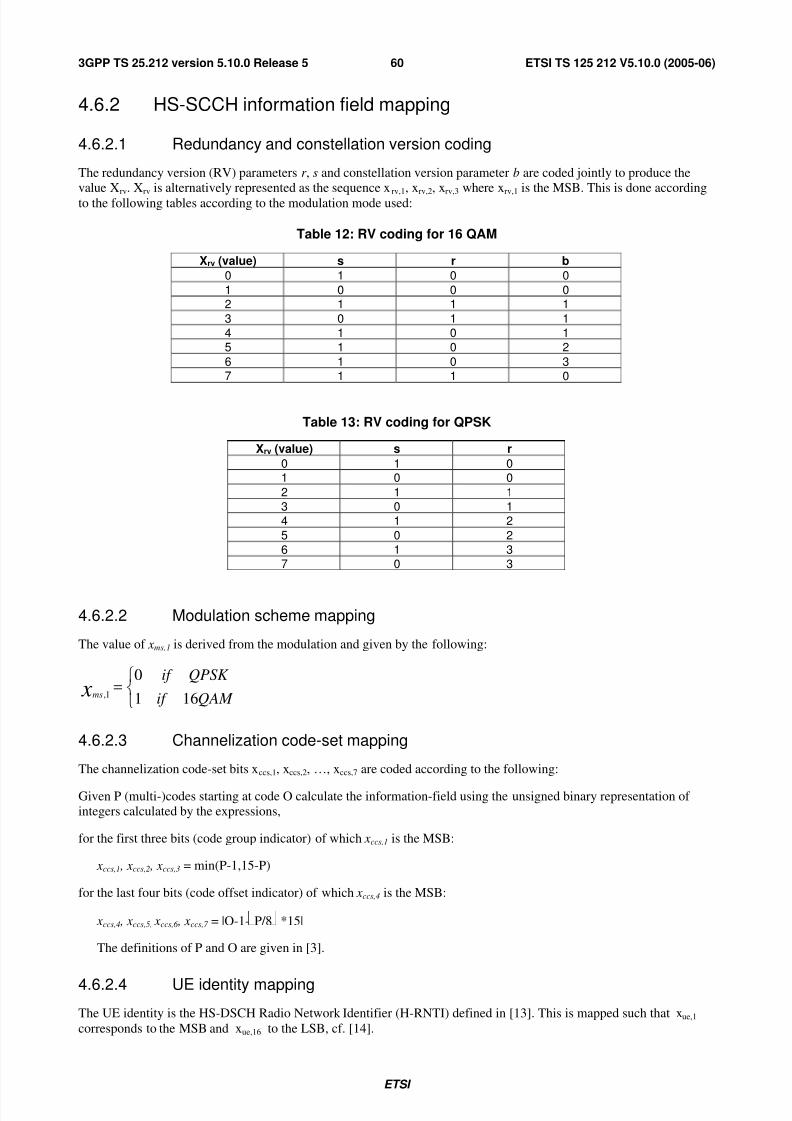
7/31/2019 Ts_125212v051000p_release5_Multiplexing and Channel Coding (FDD)
http://slidepdf.com/reader/full/ts125212v051000prelease5multiplexing-and-channel-coding-fdd 61/74
ETSI
ETSI TS 125 212 V5.10.0 (2005-06)603GPP TS 25.212 version 5.10.0 Release 5
4.6.2 HS-SCCH information field mapping
4.6.2.1 Redundancy and constellation version coding
The redundancy version (RV) parameters r , s and constellation version parameter b are coded jointly to produce thevalue Xrv. Xrv is alternatively represented as the sequence xrv,1, xrv,2, xrv,3 where xrv,1 is the MSB. This is done according
to the following tables according to the modulation mode used:
Table 12: RV coding for 16 QAM
Xrv (value) s r b
0 1 0 0
1 0 0 02 1 1 1
3 0 1 14 1 0 15 1 0 2
6 1 0 37 1 1 0
Table 13: RV coding for QPSK
Xrv (value) s r
0 1 01 0 0
2 1 13 0 14 1 2
5 0 26 1 37 0 3
4.6.2.2 Modulation scheme mapping
The value of xms,1 is derived from the modulation and given by the following:
=QAM if
QPSK if xms 161
01,
4.6.2.3 Channelization code-set mapping
The channelization code-set bits xccs,1, xccs,2, …, xccs,7 are coded according to the following:
Given P (multi-)codes starting at code O calculate the information-field using the unsigned binary representation of integers calculated by the expressions,
for the first three bits (code group indicator) of which xccs,1 is the MSB:
xccs,1 , xccs,2 , xccs,3 = min(P-1,15-P)
for the last four bits (code offset indicator) of which xccs,4 is the MSB:
xccs,4 , xccs,5, xccs,6 , xccs,7 = |O-1- P/8 *15|
The definitions of P and O are given in [3].
4.6.2.4 UE identity mapping
The UE identity is the HS-DSCH Radio Network Identifier (H-RNTI) defined in [13]. This is mapped such that xue,1
corresponds to the MSB and xue,16 to the LSB, cf. [14].
7/31/2019 Ts_125212v051000p_release5_Multiplexing and Channel Coding (FDD)
http://slidepdf.com/reader/full/ts125212v051000prelease5multiplexing-and-channel-coding-fdd 62/74
ETSI
ETSI TS 125 212 V5.10.0 (2005-06)613GPP TS 25.212 version 5.10.0 Release 5
4.6.2.5 HARQ process identifier mapping
Hybrid-ARQ process information (3 bits) xhap,1 , xhap,2 , xhap,3 is unsigned binary representation of the HARQ process
identifier where xhap,1 is MSB.
4.6.2.6 Transport block size index mapping
Transport-block size information (6 bits) xtbs,1 , xtbs,2 , … , xtbs,6 is unsigned binary representation of the Transport block
size index where xtbs,1 is MSB.
4.6.3 Multiplexing of HS-SCCH information
The channelization-code-set information xccs,1 , xccs,2 , … , xccs,7 and modulation-scheme information xms,1 are multiplexed
together. This gives a sequence of bits x1,1 , x1,2 , … , x1,8 where
x1,i = xccs,i i=1,2,… ,7
x1,i = xms,i-7 i=8
The transport-block-size information xtbs,1 , xtbs,2 , … , xtbs,6 , Hybrid-ARQ-process information xhap,1 ,xhap,2 , xhap,3,
redundancy-version information xrv,1 , xrv,2, xrv,3 and new-data indicator xnd,1 are multiplexed together. This gives a
sequence of bits x2,1 , x2,2 , … , x2,13 where
x2,i = xtbs,i i=1,2,… ,6
x2,i = xhap,i-6 i=7,8,9
x2,i = xrv,i-9 i=10,11,12
x2,i = xnd,i-12 i=13
4.6.4 CRC attachment for HS-SCCH
From the sequence of bits x1,1 , x1,2 , … , x1,8, x2,1 , x2,2 , … , x2,13 a 16 bits CRC is calculated according to Section 4.2.1.1.
This gives a sequence of bits c1 , c2 , … , c16 where
)17( k imk pc−
= k=1,2,… ,16
This sequence of bits is then masked with the UE Identity xue,1 , xue,2 , … , xue,16 and then appended to the sequence of bits
x2,1 , x2,2 , … , x2,13 to form the sequence of bits y1 , y2 , … , y29, where
yi = x2,i i=1,2,… ,13
yi = (ci-13 + xue,i-13) mod 2 i=14,15,… ,29
4.6.5 Channel coding for HS-SCCH
Rate 1/3 convolutional coding, as described in Section 4.2.3.1, is applied to the sequence of bits x1,1 ,x1,2 , … ,x1,8. Thisgives a sequence of bits z1,1 , z1,2 , … , z1,48.
Rate 1/3 convolutional coding, as described in Section 4.2.3.1, is applied to the sequence of bits y1 , y2 , … , y29. This givesa sequence of bits z2,1 , z2,2 , … , z2,111.
Note that the coded sequence lengths result from the termination of K=9 convolutional coding being fully applied.
7/31/2019 Ts_125212v051000p_release5_Multiplexing and Channel Coding (FDD)
http://slidepdf.com/reader/full/ts125212v051000prelease5multiplexing-and-channel-coding-fdd 63/74
ETSI
ETSI TS 125 212 V5.10.0 (2005-06)623GPP TS 25.212 version 5.10.0 Release 5
4.6.6 Rate matching for HS-SCCH
From the input sequence z1,1 , z1,2 , … , z1,48 the bits z1,1 , z1,2 , z1,4 , z1,8 , z1,42 , z1,45 , z1,47 , z1,48 are punctured to obtain the outputsequence r 1,1 ,r 1,2…r 1,40.
From the input sequence z2,1 , z2,2 , … , z2,111 the bits z2,1 , z2,2 , z2,3 , z2,4 , z2,5 , z2,6 , z2,7 , z2,8 , z2,12 , z2,14 , z2,15 , z2,24 , z2,42 , z2,48 , z2,54 ,
z2,57 , z2,60 , z2,66 , z2,69 , z2,96 , z2,99 , z2,101 , z2,102 , z2,104 , z2,105 , z2,106 , z2,107 , z2,108 , z2,109 , z2,110 , z2,111 are punctured to obtain theoutput sequence r 2,1 ,r 2,2…r 2,80.
4.6.7 UE specific masking for HS-SCCH
The rate matched bits r 1,1 ,r 1,2…r 1,40 shall be masked in an UE specific way using the UE identity xue,1 , xue,2 , … , xue,16 , to
produce the bits s1,1 ,s1,2…s1,40.
Intermediate code word bits bi, i=1,2…,48, are defined by endcoding the UE identity bits using the rate ½ convolutional
coding described in Section 4.2.3.1. Eight bits out of the resulting 48 convolutionally encoded bits are punctured using
the rate matching rule of Section 4.6.6 for the HS-SCCH part 1 sequence, that is, the intermediate code word bits b1,
b2, b4, b8, b42, b45, b47, b48, are punctured to obtain the 40 bit UE specific scrambling sequence c1, c2, ….c40. .
The mask output bits s1,1 ,s1,2…s1,40 are calculated as follows:
s1,k =(r 1,k + ck ) mod 2 for k = 1,2…40
4.6.8 Physical channel mapping for HS-SCCH
The HS-SCCH sub-frame is described in[2].
The sequence of bits s1,1 , s1,2 ,, … , s1,40 is mapped to the first slot of the HS-SCCH sub frame. The bits s1,k are mapped to
the PhCHs so that the bits for each PhCH are transmitted over the air in ascending order with respect to k .
The sequence of bits r 2,1 , r 2,2 ,, … ,,r 2,80 is mapped to the second and third slot of the HS-SCCH sub frame. The bits r 2,k
are mapped to the PhCHs so that the bits for each PhCH are transmitted over the air in ascending order with respect to
k .
4.7 Coding for HS-DPCCH
Data arrives to the coding unit in form of indicators for measurement indication and HARQ acknowledgement.
The following coding/multiplexing steps can be identified:
- channel coding (see subclause 4.7.1);
- mapping to physical channels (see subclause 4.7.2).
The general coding flow is shown in the figure below. This is done in parallel for the HARQ-ACK and CQI as the flows
are not directly multiplexed but are transmitted at different times.

7/31/2019 Ts_125212v051000p_release5_Multiplexing and Channel Coding (FDD)
http://slidepdf.com/reader/full/ts125212v051000prelease5multiplexing-and-channel-coding-fdd 64/74
ETSI
ETSI TS 125 212 V5.10.0 (2005-06)633GPP TS 25.212 version 5.10.0 Release 5
Physical channel mapping
Channel Coding Channel coding
PhCH
b 0 ,b 1 ...b 19
Physical channel mapping
HARQ-ACK CQI
a 0 ,a 1 ...a 4
PhCH
w 0 ,w 1 ,w ,...w 2 9
Figure 20: Coding for HS-DPCCH
4.7.1 Channel coding for HS-DPCCH
Two forms of channel coding are used, one for the channel quality information (CQI) and another for HARQ-ACK
(acknowledgement).
4.7.1.1 Channel coding for HS-DPCCH HARQ-ACK
The HARQ acknowledgement message to be transmitted, as defined in [4], shall be coded to 10 bits as shown in Table
13A. The output is denoted w0, w1,…w9.
Table 13A: Channel coding of HARQ-ACK
HARQ-ACK
message to betransmitted
w0 w1 w2 w3 w4 w5 w6 w7 w8 w9
ACK 1 1 1 1 1 1 1 1 1 1
NACK 0 0 0 0 0 0 0 0 0 0
4.7.1.2 Channel coding for HS-DPCCH channel quality information
The channel quality information is coded using a (20,5) code. The code words of the (20,5) code are a linear
combination of the 5 basis sequences denoted Mi,n defined in the table below.

7/31/2019 Ts_125212v051000p_release5_Multiplexing and Channel Coding (FDD)
http://slidepdf.com/reader/full/ts125212v051000prelease5multiplexing-and-channel-coding-fdd 65/74
ETSI
ETSI TS 125 212 V5.10.0 (2005-06)643GPP TS 25.212 version 5.10.0 Release 5
Table 14: Basis sequences for (20,5) code
i Mi,0 Mi,1 Mi,2 Mi,3 Mi,4
0 1 0 0 0 11 0 1 0 0 12 1 1 0 0 1
3 0 0 1 0 1
4 1 0 1 0 15 0 1 1 0 16 1 1 1 0 1
7 0 0 0 1 18 1 0 0 1 19 0 1 0 1 1
10 1 1 0 1 111 0 0 1 1 1
12 1 0 1 1 113 0 1 1 1 114 1 1 1 1 1
15 0 0 0 0 116 0 0 0 0 1
17 0 0 0 0 118 0 0 0 0 119 0 0 0 0 1
The CQI values 0 .. 30 as defined in [4] are converted from decimal to binary to map them to the channel quality
information bits (1 0 0 0 0) to (1 1 1 1 1) respectively. The information bit pattern (0 0 0 0 0) shall not be used in thisrelease. The channel quality information bits are a0 , a1 , a2 , a3 , a4 (where a0 is LSB and a4 is MSB). The output code
word bits bi are given by:
2mod)(,
4
0 M ab ni
nni
×=∑=
where i = 0, …, 19.
4.7.2 Physical channel mapping for HS-DPCCH
The HS-DPCCH physical channel mapping function shall map the input bits wk directly to physical channel so that bits
are transmitted over the air in ascending order with respect to k.
The HS-DPCCH physical channel mapping function shall map the input bits bk directly to physical channel so that bits
are transmitted over the air in ascending order with respect to k.

7/31/2019 Ts_125212v051000p_release5_Multiplexing and Channel Coding (FDD)
http://slidepdf.com/reader/full/ts125212v051000prelease5multiplexing-and-channel-coding-fdd 66/74
ETSI
ETSI TS 125 212 V5.10.0 (2005-06)653GPP TS 25.212 version 5.10.0 Release 5
Annex A (informative):Blind transport format detection
A.1 Blind transport format detection using fixed positions
A.1.1 Blind transport format detection using received power ratio
For the dual transport format case (the possible data rates are 0 and full rate, and CRC is only transmitted for full rate),
blind transport format detection using received power ratio can be used.
The transport format detection is then done using average received power ratio of DPDCH to DPCCH. Define the
following:
- Pc: Received power per bit of DPCCH calculated from all pilot and TPC bits per slot over a radio frame;
- Pd: Received power per bit of DPDCH calculated from X bits per slot over a radio frame;
- X: the number of DPDCH bits per slot when transport format corresponds to full rate;
- T: Threshold of average received power ratio of DPDCH to DPCCH for transport format detection.
The decision rule can then be formulated as:
If Pd/Pc >T then:
- full rate transport format detected;
else
- zero rate transport format detected.
A.1.2 Blind transport format detection using CRC
For the multiple transport format case (the possible data rates are 0, …, (full rate)/r, …, full rate, and CRC is transmitted
for all transport formats), blind transport format detection using CRC can be used.
At the transmitter, the data stream with variable number of bits from higher layers is block-encoded using a cyclic
redundancy check (CRC) and then convolutionally encoded. CRC parity bits are attached just after the data stream with
variable number of bits as shown in figure A.1.
The receiver knows only the possible transport formats (or the possible end bit position {nend}) by Layer-3 negotiation.
The receiver performs Viterbi-decoding on the soft decision sample sequence. The correct trellis path of the Viterbi-decoder ends at the zero state at the correct end bit position.
The blind transport format detection method using CRC traces back the surviving trellis path ending at the zero state
(hypothetical trellis path) at each possible end bit position to recover the data sequence. For each recovered data
sequence error-detection is performed by checking the CRC, and if there is no error, the recovered sequence is declared
to be correct.
The following variable is defined:
s(nend) = - 10 log ( (a0(nend) – amin(nend) ) / (amax(nend)-amin(nend) ) ) [dB] (Eq. 1)
where amax(nend) and amin(nend) are the maximum and minimum path-metric values among all survivors at end bit
position nend, and a0(nend) is the path-metric value at zero state.

7/31/2019 Ts_125212v051000p_release5_Multiplexing and Channel Coding (FDD)
http://slidepdf.com/reader/full/ts125212v051000prelease5multiplexing-and-channel-coding-fdd 67/74
ETSI
ETSI TS 125 212 V5.10.0 (2005-06)663GPP TS 25.212 version 5.10.0 Release 5
In order to reduce the probability of false detection (this happens if the selected path is wrong but the CRC misses the
error detection), a path selection threshold D is introduced. The threshold D determines whether the hypothetical trellis
path connected to the zero state should be traced back or not at each end bit position nend. If the hypothetical trellis path
connected to the zero state that satisfies:
s(nend) ≤ D (Eq. 2)
is found, the path is traced back to recover the frame data, where D is the path selection threshold and a design
parameter.
If more than one end bit positions satisfying Eq. 2 is found, the end bit position which has minimum value of s(nend) is
declared to be correct. If no path satisfying Eq. 2 is found even after all possible end bit positions have been exhausted,
the received frame data is declared to be in error.
Figure A-2 shows the procedure of blind transport format detection using CRC.
Data with variable number of bits CRC Empty
nend = 1 nend = 2 nend = 3 nend = 4Possible end bitpositions nend
Figure A.1: An example of data with variable number of bits.Four possible transport formats, and transmitted end bit position nend = 3

7/31/2019 Ts_125212v051000p_release5_Multiplexing and Channel Coding (FDD)
http://slidepdf.com/reader/full/ts125212v051000prelease5multiplexing-and-channel-coding-fdd 68/74
ETSI
ETSI TS 125 212 V5.10.0 (2005-06)673GPP TS 25.212 version 5.10.0 Release 5
Comparisonof S(nend)
S(nend) =< D
S(nend) > D
NG
OK
Viterbi decoding (ACS operation)
to end bit position nend
Calculation of S(nend)
Calculation of CRC parityfor recovered data
CRC
Output detectedend bit position nend’ *
Smin =< S(nend)
END
Is nend themaximum value?
Path selection
Tracing back from end bit position nend
nend = nend + 1
nend = 1Smin = Dnend’ = 0
START
Smin > S(nend)
Smin = S(nend)nend’ = nend
No
Yes
* If the value of detected nend’ is“0”, the received frame data isdeclared to be in error.
Figure A.2: Basic processing flow of blind transport format detection

7/31/2019 Ts_125212v051000p_release5_Multiplexing and Channel Coding (FDD)
http://slidepdf.com/reader/full/ts125212v051000prelease5multiplexing-and-channel-coding-fdd 69/74
ETSI
ETSI TS 125 212 V5.10.0 (2005-06)683GPP TS 25.212 version 5.10.0 Release 5
Annex B (informative):Compressed mode idle lengths
The tables B.1-B.3 show the resulting idle lengths for different transmission gap lengths, UL/DL modes and DL frametypes. The idle lengths given are calculated purely from the slot and frame structures and the UL/DL offset. They do not
contain margins for e.g. synthesizer switching.
B.1 Idle lengths for DL, UL and DL+UL compressedmode
Table B.1: Parameters for DL compressed mode
TGL DLFrame
Type
SpreadingFactor
Idle length[ms]
Transmission timeReduction method
Idle frameCombining
A 1.73 – 1.993
B 1.60 – 1.86
(S)(D) =(1,2) or (2,1)
A 2.40 – 2.664
B 2.27 – 2.53
(S)(D) =(1,3), (2,2) or (3,1)
A 3.07 – 3.335
B 2.93 – 3.19
(S)(D) = (1,4), (2,3), (3, 2) or
(4,1)
A 4.40 – 4.667
B 4.27 – 4.53
(S)(D)=(1,6), (2,5), (3,4), (4,3),
(5,2) or (6,1)
A 6.40 – 6.6610
B 6.27 – 6.53
(D)=(3,7), (4,6), (5,5), (6,4) or(7,3)
A 9.07 – 9.3314
B
512 – 4
8.93 – 9.19
Spreading factordivision by 2 or
Higher layerscheduling
(D) =(7,7)
Table B.2: Parameters for UL compressed mode
TGL SpreadingFactor
Idle length[ms]
Transmission timeReduction method
Idle frameCombining
3 2.00 (S)(D) =(1,2) or (2,1)
4 2.67 (S)(D) =(1,3), (2,2) or (3,1)
5 3.33 (S)(D) = (1,4), (2,3), (3, 2) or
(4,1)
7 4.67 (S)(D)=(1,6), (2,5), (3,4), (4,3),
(5,2) or (6,1)
10 6.67 (D)=(3,7), (4,6), (5,5), (6,4) or(7,3)
14
256 – 4
9.33
Spreading factordivision by 2 or
Higher layerscheduling
(D) =(7,7)

7/31/2019 Ts_125212v051000p_release5_Multiplexing and Channel Coding (FDD)
http://slidepdf.com/reader/full/ts125212v051000prelease5multiplexing-and-channel-coding-fdd 70/74
ETSI
ETSI TS 125 212 V5.10.0 (2005-06)693GPP TS 25.212 version 5.10.0 Release 5
Table B.3: Parameters for combined UL/DL compressed mode
TGL DLFrameType
SpreadingFactor
Idle length[ms]
Transmission timeReduction method
Idle frameCombining
3 1.47 – 1.73 (S)(D) =(1,2) or (2,1)
4 2.13 – 2.39 (S)(D) =(1,3), (2,2) or (3,1)
5 2.80 – 3.06 (S)(D) = (1,4), (2,3), (3, 2) or
(4,1)
7 4.13 – 4.39 (S)(D)=(1,6), (2,5), (3,4), (4,3),
(5,2) or (6,1)
10 6.13 – 6.39 (D)=(3,7), (4,6), (5,5), (6,4) or(7,3)
14
A or B DL:
512 – 4
UL:256 – 4
8.80 – 9.06
Spreading factor
division by 2 orHigher layerscheduling
(D) =(7,7)
(S): Single-frame method as shown in figure 14 (1).
(D): Double-frame method as shown in figure 14 (2). (x,y) indicates x: the number of idle slots in the first frame,
y: the number of idle slots in the second frame.
NOTE: Compressed mode by spreading factor reduction is not supported when SF=4 is used in normal mode

7/31/2019 Ts_125212v051000p_release5_Multiplexing and Channel Coding (FDD)
http://slidepdf.com/reader/full/ts125212v051000prelease5multiplexing-and-channel-coding-fdd 71/74
ETSI
ETSI TS 125 212 V5.10.0 (2005-06)703GPP TS 25.212 version 5.10.0 Release 5
Annex C (informative):Change history
Change history
Date TSG # TSG Doc. CR Rev Subject/Comment Old New
RAN_05 RP-99588 - Approved at TSG RAN #5 and placed under Change Control - 3.0.0
14/01/00 RAN_06 RP-99680 001 3 Correction of rate matching parameters for repetition after 1stunterleaving in 25.212
3.0.0 3.1.0
14/01/00 RAN_06 RP-99680 004 - Changing the initial offset value for convolutional code ratematching
3.0.0 3.1.0
14/01/00 RAN_06 RP-99681 005 1 Introduction of compressed mode by higher layer scheduling 3.0.0 3.1.0
14/01/00 RAN_06 RP-99679 008 - Editorial corrections to TS 25.212 3.0.0 3.1.0
14/01/00 RAN_06 RP-99680 009 - Removal of SFN multiplexing 3.0.0 3.1.0
14/01/00 RAN_06 RP-99680 010 1 Clarification of bit separation and collection 3.0.0 3.1.0
14/01/00 RAN_06 RP-99680 011 2 Connection between TTI and CFN 3.0.0 3.1.0
14/01/00 RAN_06 RP-99680 012 2 Zero length transport blocks 3.0.0 3.1.0
14/01/00 RAN_06 RP-99679 014 - Update of channel coding sections 3.0.0 3.1.0
14/01/00 RAN_06 RP-99680 016 - Removal of TrCH restriction in DSCH CCTrCH 3.0.0 3.1.0
14/01/00 RAN_06 RP-99681 017 - 20 ms RACH message length 3.0.0 3.1.0
14/01/00 RAN_06 RP-99680 018 - Minimum SF in UL 3.0.0 3.1.0
14/01/00 RAN_06 RP-99680 024 - Rate matching parameter determination in DL and fixed positions 3.0.0 3.1.0
14/01/00 RAN_06 RP-99680 026 1 Corrections to TS 25.212 3.0.0 3.1.0
14/01/00 RAN_06 RP-99679 027 - Modification of BTFD description in 25.212 Annex 3.0.0 3.1.0
14/01/00 RAN_06 RP-99681 028 - TFCI coding and mapping including compressed mode 3.0.0 3.1.0
14/01/00 - - - Change history was added by the editor 3.1.0 3.1.1
31/03/00 RAN_07 RP-000061 025 2 CR for parity bit attachment to 0 bit transport block 3.1.1 3.2.031/03/00 RAN_07 RP-000061 029 1 Limitations of blind transport format detection 3.1.1 3.2.031/03/00 RAN_07 RP-000061 034 1 Clarification of fixed position rate matching 3.1.1 3.2.031/03/00 RAN_07 RP-000061 035 1 Clarification of DL compressed mode 3.1.1 3.2.031/03/00 RAN_07 RP-000061 036 - Reconfiguration of TFCS 3.1.1 3.2.031/03/00 RAN_07 RP-000061 037 1 Removal of fixed gap position in 25.212 3.1.1 3.2.031/03/00 RAN_07 RP-000061 038 2 Definition clarification for TS 25.212 3.1.1 3.2.031/03/00 RAN_07 RP-000061 039 1 Clarification on TFCI coding input 3.1.1 3.2.031/03/00 RAN_07 RP-000061 041 2 Correction of UL compressed mode by higher layer scheduling 3.1.1 3.2.031/03/00 RAN_07 RP-000061 042 5 Downlink Compressed Mode by puncturing 3.1.1 3.2.031/03/00 RAN_07 RP-000061 044 - Modification of Turbo code internal interleaver 3.1.1 3.2.031/03/00 RAN_07 RP-000061 045 - Editorial corrections 3.1.1 3.2.031/03/00 RAN_07 RP-000061 046 - SF/2 method: DTX insertion after 2nd interleaver 3.1.1 3.2.031/03/00 RAN_07 RP-000061 047 1 TFCI coding for FDD 3.1.1 3.2.031/03/00 RAN_07 RP-000061 048 - Mapping of TFCI in downlink compressed mode 3.1.1 3.2.031/03/00 RAN_07 RP-000061 049 - Editorial changes to Annex A 3.1.1 3.2.031/03/00 RAN_07 RP-000061 050 - Removal of rate matching attribute setting for RACH 3.1.1 3.2.031/03/00 RAN_07 RP-000061 052 - Padding Function for Turbo coding of small blocks 3.1.1 3.2.031/03/00 RAN_07 RP-000061 055 2 Clarifications relating to DSCH 3.1.1 3.2.031/03/00 RAN_07 RP-000061 056 - Editorial modification of uplink shifting parameter calculation for
turbo code puncturing3.1.1 3.2.0
31/03/00 RAN_07 RP-000062 059 1 Revision: Editorial correction to the calculation of Rate Matchingparameters 3.1.1 3.2.0
31/03/00 RAN_07 RP-000062 060 1 Editorial changes of channel coding section 3.1.1 3.2.031/03/00 RAN_07 RP-000062 061 - Removal of DL compressed mode by higher layer scheduling with
fixed positions3.1.1 3.2.0
26/06/00 RAN_08 RP-000266 066 1 Section 4.4.5 and table 9 is moved to informative annex 3.2.0 3.3.0
26/06/00 RAN_08 RP-000266 068 - Editorial modifications of 25.212 3.2.0 3.3.0
26/06/00 RAN_08 RP-000266 069 - Removal of BTFD for flexible positions in Release 99 3.2.0 3.3.0
26/06/00 RAN_08 RP-000266 070 1 Editorial modifications 3.2.0 3.3.0
26/06/00 RAN_08 RP-000266 071 1 Corrections and editorial modifications of 25.212 for 2nd insertionof DTX bits for CM
3.2.0 3.3.0
26/06/00 RAN_08 RP-000266 072 4 Corrections to 25.212 (Rate Matching, p-bit insertion, PhCHsegmentation)
3.2.0 3.3.0
26/06/00 RAN_08 RP-000266 073 - Editorial correction in 25.212 coding/multiplexing 3.2.0 3.3.0
26/06/00 RAN_08 RP-000266 074 2 Bit separation of the Turbo encoded data 3.2.0 3.3.0
26/06/00 RAN_08 RP-000266 076 1 Revision of code block segmentation description 3.2.0 3.3.026/06/00 RAN_08 RP-000266 077 - Clarifications for TFCI coding 3.2.0 3.3.0
26/06/00 RAN_08 RP-000266 078 2 Clarifying the rate matching parameter setting for the RACH andBCH
3.2.0 3.3.0
26/06/00 RAN_08 RP-000266 080 - Clarification on BTFD utilisation (single CCTrCH) 3.2.0 3.3.0

7/31/2019 Ts_125212v051000p_release5_Multiplexing and Channel Coding (FDD)
http://slidepdf.com/reader/full/ts125212v051000prelease5multiplexing-and-channel-coding-fdd 72/74
ETSI
ETSI TS 125 212 V5.10.0 (2005-06)713GPP TS 25.212 version 5.10.0 Release 5
Change history
Date TSG # TSG Doc. CR Rev Subject/Comment Old New
26/06/00 RAN_08 RP-000266 081 - Correction of order of checking TFC during flexible position RMparameter determination
3.2.0 3.3.0
26/06/00 RAN_08 RP-000266 082 - Editorial corrections in channel coding section 3.2.0 3.3.0
26/06/00 RAN_08 RP-000266 083 - Correction for bit separation and bit collection 3.2.0 3.3.0
26/06/00 RAN_08 RP-000266 084 1 Correction on the spreading factor selection for the RACH 3.2.0 3.3.0
23/09/00 RAN_09 RP-000341 079 - Clarification of compressed mode terminology 3.3.0 3.4.023/09/00 RAN_09 RP-000341 085 1 Editorial corrections in Turbo code internal interleaver section 3.3.0 3.4.0
23/09/00 RAN_09 RP-000341 086 1 Clarification on DL slot format for compressed mode by SF/2 3.3.0 3.4.0
23/09/00 RAN_09 RP-000341 087 - Corrections 3.3.0 3.4.0
23/09/00 RAN_09 RP-000341 088 1 Clarifications to TS 25.212 3.3.0 3.4.0
23/09/00 RAN_09 RP-000341 089 - Correction regarding DSCH 3.3.0 3.4.0
23/09/00 RAN_09 RP-000341 090 - Correction regarding CPCH 3.3.0 3.4.0
23/09/00 RAN_09 RP-000341 092 1 Bit separation and collection for rate matching 3.3.0 3.4.0
23/09/00 RAN_09 RP-000341 093 - Puncturing Limit definition in WG1 specification 3.3.0 3.4.0
15/12/00 RAN_10 RP-000538 094 2 Correction of BTFD limitations 3.4.0 3.5.0
15/12/00 RAN_10 RP-000538 096 - Compressed mode by puncturing 3.4.0 3.5.0
15/12/00 RAN_10 RP-000538 097 - Clarification on the Ci formula 3.4.0 3.5.0
15/12/00 RAN_10 RP-000538 099 - Editorial modification in RM section 3.4.0 3.5.0
15/12/00 RAN_10 RP-000538 100 1 Editorial corrections in TS 25.212 3.4.0 3.5.0
15/12/00 RAN_10 RP-000538 101 - Correction to code block segmentation 3.4.0 3.5.0

7/31/2019 Ts_125212v051000p_release5_Multiplexing and Channel Coding (FDD)
http://slidepdf.com/reader/full/ts125212v051000prelease5multiplexing-and-channel-coding-fdd 73/74
ETSI
ETSI TS 125 212 V5.10.0 (2005-06)723GPP TS 25.212 version 5.10.0 Release 5
Change history
Date TSG # TSG Doc. CR Rev Subject/Comment Old New
16/03/01 RAN_11 - - - Approved as Release 4 specification (v4.0.0) at TSG RAN #11 3.5.0 4.0.0
15/06/01 RAN_12 RP-010332 106 - Correction of compressed mode by puncturing 4.0.0 4.1.0
15/06/01 RAN_12 RP-010332 108 1 Dual transport format detection 4.0.0 4.1.0
15/06/01 RAN_12 RP-010332 112 1 Correction for downlink rate matching for the DSCH 4.0.0 4.1.0
21/09/01 RAN_13 RP-010519 115 - Correction of PDSCH spreading factor signalling 4.1.0 4.2.0
14/12/01 RAN_14 RP-010737 118 - Clarification of compressed mode 4.2.0 4.3.014/12/01 RAN_14 RP-010737 122 - Support of multiple CCTrChs of dedicated type 4.2.0 4.3.0
08/03/02 RAN_15 RP-020231 128 2 Removal of channel coding option 'no coding' for FDD 4.3.0 4.4.0
08/03/02 RAN_15 RP-020054 123 4 Inclusion of flexible hard split mode TFCI operation 4.3.0 5.0.0
08/03/02 RAN_15 RP-020058 126 1 Changes to 25.212 for HSDPA work item 4.3.0 5.0.0
07/06/02 RAN_16 RP-020308 136 - Downlink bit mapping 5.0.0 5.1.0
07/06/02 RAN_16 RP-020316 130 5 Correction of Errata noted by RAN1 delegates 5.0.0 5.1.0
07/06/02 RAN_16 RP-020316 131 2 Removal of inconsistencies and ambiguities in the HARQdescription
5.0.0 5.1.0
07/06/02 RAN_16 RP-020316 132 - Rate Matching and Channel Coding for HS-SCCH 5.0.0 5.1.0
07/06/02 RAN_16 RP-020316 137 - Basis sequences for HS-DPCCH Channel Quality information code 5.0.0 5.1.0
07/06/02 RAN_16 RP-020316 145 5 UE specific masking for HS-SCCH part1 5.0.0 5.1.0
14/09/02 RAN_17 RP-020582 141 1 Bit scrambling for HS-DSCH 5.1.0 5.2.0
15/09/02 RAN_17 RP-020582 148 Physical channel mapping for HS-DPCCH 5.1.0 5.2.0
15/09/02 RAN_17 RP-020582 149 HARQ bit collection 5.1.0 5.2.0
15/09/02 RAN_17 RP-020582 150 1 Coding for HS-SCCH 5.1.0 5.2.015/09/02 RAN_17 RP-020582 151 Correction to UE specific masking for HS-SCCH part1 5.1.0 5.2.0
15/09/02 RAN_17 RP-020568 155 2 Clarification of the definition of layer 1 transport channel numbers 5.1.0 5.2.0
15/09/02 RAN_17 RP-020573 157 Numbering Corrections 5.1.0 5.2.0
15/09/02 RAN_17 RP-020645 158 1 Specification of H-RNTI to UE identity mapping 5.1.0 5.2.0
20/12/02 RAN_18 RP-020846 163 - Correction of CQI index to bit mapping 5.2.0 5.3.0
20/12/02 RAN_18 RP-020846 164 - Correction of mapping of HARQ-ACK 5.2.0 5.3.0
26/03/03 RAN_19 RP-030134 165 1 Correction of CQI index to bit mapping 5.3.0 5.4.0
26/03/03 RAN_19 RP-030134 166 3 Correction of bit scrambling of HS-DSCH 5.3.0 5.4.0
26/03/03 RAN_19 RP-030134 Correction of subscript for modulation scheme information 5.3.0 5.4.0
23/06/03 RAN_20 RP-030272 172 1 Clarification of TPC and Pilot transmission with STTD incompressed mode
5.4.0 5.5.0
23/06/03 RAN_20 RP-030272 173 2 Correction on the flexible TFCI coding in the DSCH hard split modefor Rel5
5.4.0 5.5.0
21/09/03 RAN_21 RP-030456 178 4 Clarification on Single Transport Format Detection 5.5.0 5.6.0
21/09/03 RAN_21 RP-030456 179 - Correction on table number in first interleave description 5.5.0 5.6.021/09/03 RAN_21 RP-030456 180 3 Broadening the conditions that require UEs to perform BTFD for the
case of HS-DSCH reception5.5.0 5.6.0
06/01/04 RAN_22 RP-030647 183 - Clarification of the CRC attachment procedure for HS-SCCH 5.6.0 5.7.0
06/01/04 RAN_22 RP-030647 184 1 Correction of UE identity notation 5.6.0 5.7.0
06/01/04 RAN_22 RP-030644 185 - HARQ process identifier mapping 5.6.0 5.7.0
06/01/04 RAN_22 RP-030712 186 Alignment of terminology across 3GPP documentation 5.6.0 5.7.0
23/03/04 RAN_23 RP-040085 181 3 CCTrCH definition extension to HS-DSCH 5.7.0 5.8.0
09/06/04 RAN_24 RP-040230 190 1 Clarification of Channelization Code-Set Mapping 5.8.0 5.9.0
16/06/05 RAN_28 RP-050241 202 - Correction of HSDPA Bit Separation 5.9.0 5.10.0
16/06/05 RAN_28 RP-050250 207 1 Feature Clean Up: Removal of 'CPCH' 5.9.0 5.10.0
16/06/05 RAN_28 RP-050248 209 - Feature Clean Up: Removal of DSCH (FDD mode) 5.9.0 5.10.0
16/06/05 RAN_28 RP-050243 211 1 Feature Clean-Up: Removal of 80 ms TTI for DCH for all othercases but when the UE supports SF512
5.9.0 5.10.0
16/06/05 RAN_28 RP-050249 213 1 Feature clean up: Removal of the 'compressed mode by
puncturing'
5.9.0 5.10.0

7/31/2019 Ts_125212v051000p_release5_Multiplexing and Channel Coding (FDD)
http://slidepdf.com/reader/full/ts125212v051000prelease5multiplexing-and-channel-coding-fdd 74/74
ETSI TS 125 212 V5.10.0 (2005-06)733GPP TS 25.212 version 5.10.0 Release 5
History
Document history
V5.0.0 March 2002 Publication
V5.1.0 June 2002 Publication
V5.2.0 September 2002 Publication
V5.3.0 December 2002 Publication
V5.4.0 March 2003 Publication
V5.5.0 June 2003 Publication
V5.6.0 September 2003 Publication
V5.7.0 December 2003 Publication
V5.8.0 March 2004 Publication
V5.9.0 June 2004 Publication
V5.10.0 June 2005 Publication