ts 185 001 - v1.1.1 - telecommunication and internet converged
TRANSCRIPT
ETSI TS 185 001 V1.1.1 (2005-11)
Technical Specification
Telecommunication and Internet converged Servicesand Protocols for Advanced Networking (TISPAN);
Next Generation Network (NGN);Quality of Service (QoS) Framework and Requirements
ETSI
ETSI TS 185 001 V1.1.1 (2005-11) 2
Reference DTS/TISPAN-05008-NGN
Keywords QoS, quality
ETSI
650 Route des Lucioles F-06921 Sophia Antipolis Cedex - FRANCE
Tel.: +33 4 92 94 42 00 Fax: +33 4 93 65 47 16
Siret N° 348 623 562 00017 - NAF 742 C
Association à but non lucratif enregistrée à la Sous-Préfecture de Grasse (06) N° 7803/88
Important notice
Individual copies of the present document can be downloaded from: http://www.etsi.org
The present document may be made available in more than one electronic version or in print. In any case of existing or perceived difference in contents between such versions, the reference version is the Portable Document Format (PDF).
In case of dispute, the reference shall be the printing on ETSI printers of the PDF version kept on a specific network drive within ETSI Secretariat.
Users of the present document should be aware that the document may be subject to revision or change of status. Information on the current status of this and other ETSI documents is available at
http://portal.etsi.org/tb/status/status.asp
If you find errors in the present document, please send your comment to one of the following services: http://portal.etsi.org/chaircor/ETSI_support.asp
Copyright Notification
No part may be reproduced except as authorized by written permission. The copyright and the foregoing restriction extend to reproduction in all media.
© European Telecommunications Standards Institute 2005.
All rights reserved.
DECTTM, PLUGTESTSTM and UMTSTM are Trade Marks of ETSI registered for the benefit of its Members. TIPHONTM and the TIPHON logo are Trade Marks currently being registered by ETSI for the benefit of its Members. 3GPPTM is a Trade Mark of ETSI registered for the benefit of its Members and of the 3GPP Organizational Partners.
ETSI
ETSI TS 185 001 V1.1.1 (2005-11) 3
Contents
Intellectual Property Rights ................................................................................................................................5
Foreword.............................................................................................................................................................5
1 Scope ........................................................................................................................................................6
2 References ................................................................................................................................................6
3 Definitions and abbreviations...................................................................................................................7 3.1 Definitions..........................................................................................................................................................7 3.2 Abbreviations .....................................................................................................................................................7
4 Introduction ..............................................................................................................................................8
5 QoS Generic concepts ..............................................................................................................................8 5.1 QoS and Network Performance..........................................................................................................................8 5.2 Performance objectives ......................................................................................................................................8 5.3 End-to-end and bearer QoS ................................................................................................................................8 5.4 Guaranteed and relative QoS..............................................................................................................................9
6 QoS Framework Model ............................................................................................................................9 6.1 Framework Model ..............................................................................................................................................9 6.1.1 Processes.....................................................................................................................................................10 6.1.2 Levels..........................................................................................................................................................10 6.2 Application to QoS...........................................................................................................................................11
7 NGN QoS Requirements ........................................................................................................................12
8 QoS Classes............................................................................................................................................13 8.1 ITU-T Recommendation Y.1541 QoS Classes.................................................................................................13 8.2 TS 123 107 QoS Classes ..................................................................................................................................14 8.3 Mapping between ITU-T (Y.1541) and 3GPP (TS 123 107) QoS Classes ......................................................14 8.3.1 Context........................................................................................................................................................14 8.3.2 Hypothesis ..................................................................................................................................................15 8.3.3 Y.1541 to TS 123 107.................................................................................................................................15 8.3.4. TS 123 107 to Y.1541.................................................................................................................................15 8.3.5 Limitations..................................................................................................................................................18
9 Codecs ....................................................................................................................................................18
10 QoS Scenarios ........................................................................................................................................18 10.1 Scenario 1 - Proxied QoS with policy-push .....................................................................................................19 10.2 Scenario 2 - User-requested QoS with policy-push-pull ..................................................................................20 10.3 Scenario 3 - User-requested QoS with policy-pull ...........................................................................................20
11 QoS Architecture Requirements.............................................................................................................21 11.1 Architectural requirements ...............................................................................................................................21 11.2 QoS architecture ...............................................................................................................................................22
12 QoS Signalling Requirements ................................................................................................................23 12.1 QoS Signalling Requirements in Call/Connection Control Reference Point....................................................23 12.2 QoS Signalling Requirements in Network Control Reference Point................................................................24 12.3 QoS Signalling Requirements in Switch Control Reference Point...................................................................24
Annex A (informative): List of Audio and Video Codecs for conversational applications......................25
A.1 Audio Narrow Band (300 Hz to 3 400 Hz) ............................................................................................26
A.2 Audio Wide Band (50 Hz to 7 000 Hz)..................................................................................................27
A.3 Audio Narrow and WideBand................................................................................................................28
A.4 Foreseen extensions of existing Codecs (new Annexes under standardization in ITU-T).....................28

ETSI
ETSI TS 185 001 V1.1.1 (2005-11) 4
A.5 Video ......................................................................................................................................................29
History ..............................................................................................................................................................30
ETSI
ETSI TS 185 001 V1.1.1 (2005-11) 5
Intellectual Property Rights IPRs essential or potentially essential to the present document may have been declared to ETSI. The information pertaining to these essential IPRs, if any, is publicly available for ETSI members and non-members, and can be found in ETSI SR 000 314: "Intellectual Property Rights (IPRs); Essential, or potentially Essential, IPRs notified to ETSI in respect of ETSI standards", which is available from the ETSI Secretariat. Latest updates are available on the ETSI Web server (http://webapp.etsi.org/IPR/home.asp).
Pursuant to the ETSI IPR Policy, no investigation, including IPR searches, has been carried out by ETSI. No guarantee can be given as to the existence of other IPRs not referenced in ETSI SR 000 314 (or the updates on the ETSI Web server) which are, or may be, or may become, essential to the present document.
Foreword This Technical Specification (TS) has been produced by ETSI Technical Committee Telecommunications and Internet converged Services and Protocols for Advanced Networking (TISPAN).
ETSI
ETSI TS 185 001 V1.1.1 (2005-11) 6
1 Scope The present document provides a set of generic QoS concepts for NGN, provides a QoS Framework Model and describes the requirements for the delivery of QoS in TISPAN NGN. The present document is release independent.
2 References The following documents contain provisions which, through reference in this text, constitute provisions of the present document.
• References are either specific (identified by date of publication and/or edition number or version number) or non-specific.
• For a specific reference, subsequent revisions do not apply.
• For a non-specific reference, the latest version applies.
Referenced documents which are not found to be publicly available in the expected location might be found at http://docbox.etsi.org/Reference.
[1] ITU-T Recommendation G.1000 (2001): "Communications Quality of Service: A framework and definitions".
[2] ITU-T Recommendation G.1010 (2001): "End-user multimedia QoS categories".
[3] ITU-T Recommendation M.2301 (2002): "Performance objectives and procedures for provisioning and maintenance of IP-based networks".
[4] ITU-T Recommendation Y.1540 (2002): "Internet protocol data communication service - IP packet transfer and availability performance parameters".
[5] ITU-T Recommendation Y.1541 (2002): "Network performance objectives for IP-based services".
[6] ETSI TS 123 107: "Digital cellular telecommunications system (Phase 2+); Universal Mobile Telecommunications System (UMTS); Quality of Service (QoS) concept and architecture (3GPP TS 23.107 Release 6)".
[7] ITU-T Recommendation G.711: "Pulse code modulation (PCM) of voice frequencies".
[8] ITU-T Recommendation G.729: "Coding of speech at 8 kbit/s using conjugate-structure algebraic-code-excited linear-prediction (CS-ACELP)".
[9] IETF RFC 3951: "Internet Low Bit Rate Codec (iLBC)".
[10] ITU-T Recommendation G.722.2: "Wideband coding of speech at around 16 kbit/s using Adaptive Multi-Rate Wideband (AMR-WB)".
[11] ISO/IEC 14496-3: "Information technology - Coding of audio-visual objects - Part 3: Audio".
[12] ITU-T Recommendation H.263: "Video coding for low bit rate communication".
[13] ITU-T Recommendation H.264: "Advanced video coding for generic audiovisual services".

ETSI
ETSI TS 185 001 V1.1.1 (2005-11) 7
3 Definitions and abbreviations
3.1 Definitions For the purposes of the present document, the following terms and definitions apply:
guaranteed QoS: traffic delivery service with numerical bounds on some or all of the QoS parameters
NOTE: These bounds may be physical limits, or enforced limits such as those encountered through mechanisms like rate policing. The bounds may result from designating a class of network performance objectives for packet transfer.
relative QoS: traffic delivery service without absolute bounds on the achieved bandwidth, packet delay or packet loss rates
NOTE: It describes the circumstances where certain classes of traffic are handled differently from other classes of traffic, and the classes achieve different levels of QoS.
3.2 Abbreviations For the purposes of the present document, the following abbreviations apply:
AMR Adaptive MultiRate speech codec ATM Asynchronous Transfer Mode BER Bit Error Rate CCRP Call/Connection Control Reference Point CDMA Code Division Multiple Access COPS Common Open Policy Service DCME Digital Circuit Multiplication Equipment DECT Digital Enhanced Cordless Telecommunications DSL Digital Subscriber Line ER Error Ratio GSM Global System for Mobile communication IPDV IP Packet Delay Variation IPER IP Packet Error Ratio IPLR IP Packet Loss Ratio IPTD IP Packet Transfer Delay LAN Local Area Network MPEG Moving Picture Experts Group MPLS Multi Protocol Label Switching NCRP Network Control Reference Point NGN Next Generation Network NSIS Next Steps In Signalling PSTN Public Switched Telephone Network QoS Quality of Service RACF Resource and Admission Control Functions RACS Resource and Admission Control Subsystem RSVP Resource ReserVation Protocol SCRP Switch Control Reference Point SDU Service Data Unit SIP Session Initiation Protocol SPDF Service Policy Decision Functions UMTS Universal Mobile Telecommunication System UNI User-to-Network Interface VoIP Voice over IP VTC Video TeleConferencing service WB-AMR Wide Band - Adaptive MultiRate speech codec WLAN Wireless Local Area Network
ETSI
ETSI TS 185 001 V1.1.1 (2005-11) 8
4 Introduction The present document defines the generic QoS concepts for NGN and provides a QoS Framework Model. The present document is release independent. TISPAN deliverables which have a bearing on QoS should indicate, which QoS requirements are met for each release.
The QoS requirements include QoS classes, codecs, QoS control mechanisms, QoS architecture, QoS signalling.
Annex A identifies, for information, a list of Audio and Video Codecs for conversational applications.
5 QoS Generic concepts
5.1 QoS and Network Performance The distinction between QoS and Network Performance, as well as the various viewpoints of QoS, are illustrated in ITU-T Recommendation G.1000 [1].
The end-to-end service as well as a number of in-network services have QoS requirements. These must be fulfilled by the network in order to meet the QoS requirements. In terms of network performance, we engineer and monitor the network so that services get the QoS they require.
5.2 Performance objectives The NGN performance objectives should be based on the ITU-T Recommendation M.2301 [3]. This recommendation provides performance objectives and procedures for provisioning and maintenance of IP networks owned by different operators. This is regardless of the transport technology supporting the IP network and the higher layers to be implemented over IP. These objectives include error performance, delay performance and availability. This Recommendation defines the parameters and their associated objectives based on the principles in ITU-T Recommendation Y.1540 [4].
ITU-T Recommendation Y.1540 [4] also provides, in an Appendix, guidance on the performance objectives and limits for IP network resources (e.g. routers, sub-networks etc.), which are owned and managed by a single operator. However, the allocation of performance inside an IP network operator's domain or network portion is the responsibility of each operator to ensure the end-to-end performance over their domain or network portion meets the limits given in ITU-T Recommendation Y.1540 [4].
ITU-T Recommendation Y.1540 [4] provides a general framework for applying these limits (see clause 8).
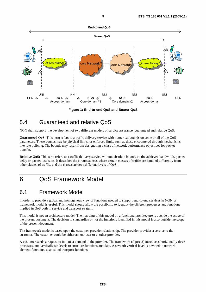
5.3 End-to-end and bearer QoS The standardization work traditionally distinguishes between tele-services, which operated across terminals and networks (e.g. mouth-ear for voice) and bearer services that excluded terminals (from UNI to UNI). In an opened and deregulated market, it is not always possible to control the user's domestic installation. Previously, the QoS specifications have been focused on end-to-end QoS. But in an NGN environment, the QoS at the bearer service level should be taken into account. The bearer service level is the level addressed by ITU-T Recommendation Y.1541 [5] and TS 123 107 [6].
ETSI
ETSI TS 185 001 V1.1.1 (2005-11) 9
NGNAccess domain
NGNCore domain #1
CPNNNIUNI NNI
Access NetworkAccess Network Core Network Core Network Access NetworkAccess Network
NGNCore domain #2
NGNAccess domain
NNI UNICPN
Bearer QoS
End-to-end QoS
Figure 1: End-to-end QoS and Bearer QoS
5.4 Guaranteed and relative QoS NGN shall support the development of two different models of service assurance: guaranteed and relative QoS.
Guaranteed QoS: This term refers to a traffic delivery service with numerical bounds on some or all of the QoS parameters. These bounds may be physical limits, or enforced limits such as those encountered through mechanisms like rate policing. The bounds may result from designating a class of network performance objectives for packet transfer.
Relative QoS: This term refers to a traffic delivery service without absolute bounds on the achieved bandwidth, packet delay or packet loss rates. It describes the circumstances where certain classes of traffic are handled differently from other classes of traffic, and the classes achieve different levels of QoS.
6 QoS Framework Model
6.1 Framework Model In order to provide a global and homogenous view of functions needed to support end-to-end services in NGN, a framework model is useful. This model should allow the possibility to identify the different processes and functions implied in QoS both in service and transport stratum.
This model is not an architecture model. The mapping of this model on a functional architecture is outside the scope of the present document. The decision to standardize or not the functions identified in this model is also outside the scope of the present document.
The framework model is based upon the customer-provider relationship. The provider provides a service to the customer. The customer could be either an end-user or another provider.
A customer sends a request to initiate a demand to the provider. The framework (figure 2) introduces horizontally three processes, and vertically six levels to structure functions and data. A seventh vertical level is devoted to network element functions, also called transport functions.

ETSI
ETSI TS 185 001 V1.1.1 (2005-11) 10
SERVICE MEDIATION
SERVICE EXECUTION
OFFERS
RESOURCE PROCESSING
NETWORK ELEMENT
INVOCATION (DYNAMIC
CONTROL PLANE) SUBSCRIPTION/ PROVISIONING
Customer
AFTER - SALES
PROCESSES / LEVELS Service request
Service use
Transport
RESOURCE MEDIATION
NETWORK PROCESSING
NETWORK ELEMENT PROCESSING
SERVICE PROCESSING
Figure 2: Framework model
6.1.1 Processes
Processes are related to the service lifecycle. They structure actions undertaken by providers in answer to customers' requests. The proposed processes are the following:
1) Subscription/Provisioning: this process deals with actions that follow customers' subscriptions: customer care (contracts, customer profiles), dimensioning, deployment and network configuration management.
2) Invocation: following a service invocation request, this process is in charge of service and resource controls to support services in real-time (or on-demand).
3) After-Sales: network performance report, quality of services and faults are handled by this process. It also manages measurements and monitoring. Customers might ask for QoS information relevant to the service.
In this framework, we identify two management processes (Subscription/Provisioning and After-Sales), and one process which corresponds to the dynamic control plane (Invocation).
6.1.2 Levels
Each process is divided into two parts: Services Processing and Resources Processing, each comprising of three levels. The proposed levels are the following:
1) Service Mediation or Front Office: this optional level is intermediary between the customer and service offers. It manages catalogues of service providers, for example in the form of "yellow pages" indicating the main attributes of provided services. It can deal with user requests to direct them to the appropriate service providers.
2) Offers or Back Office: this level is intermediary between the service mediation and service execution. It proposes offers, i.e. bundles of one or more services to the customer. It also deals with the customer's subscription, the customer's identification and authentication in order to allow him to use the subscribed services in an offer.

ETSI
ETSI TS 185 001 V1.1.1 (2005-11) 11
3) Service Execution: this level is in charge of the planning and the development of services. In the Invocation process, it ensures the execution of a telecommunications service that is dynamically requested by the customer.
4) Resource Mediation: this level is intermediary between Service Execution and resource processing. It first ensures the adaptation between service instance and resources by translating service parameters into resource parameters. This level is then in charge of resource positioning in order to support the customer's service. It identifies the sub-networks in accordance with the needed QoS. This level makes the Resource Processing independent from the Service Processing and therefore is particularly relevant in NGN architectures.
5) Network Resource Processing: this level is in charge of network resource deployment in order to meet demands of the customer's service. It identifies and monitors resources required to support the service. It computes topological paths (nodes, interfaces/links) and constraints to transfer flows.
6) Network Element Resource Processing: this level is in charge of resource network element deployment. It identifies and monitors resources at the Network Element level (matrix connection, interface, port, etc.). These functions are in charge of two main actions in the Invocation process: to select physical paths and to route data.
7) Network Element or Transport: this level corresponds to transport functions. An example is termination functions (traffic filtering, policing, etc.).
6.2 Application to QoS The previous general framework model can be applied to QoS (figure 3).
SERVICE MEDIATION
SERVICE EXECUTION
OFFERS
Service Use Request (QoS)
Service use
RESOURCE MEDIATION
NETWORKPROCESSING
NETWORKELEMENT PROCESSING
QoSSUBSCRIPTION
SELECTION OF SERVICE PROVIDER , QoS , COST
QoS REQUIREMENT
E2E RESOURCE QoS PERFORMANCE
QoS-BASED RESOURCE SELECTION
QoS - BASED NETWORK RESOURCE CONFIGURATION
NETWORK RESOURCE QoS CONTROL
MEASURED RESOURCE STATE
NET. ELEMENT CONFIG. &QoS RESOURCE
PROVISIONAL STATES
NET. ELEMENTRESOURCE QoS CONTROL
FINAL QoS
QoS Monitoring& Measures
Provisioning (in advance)
Invocation (on demand)
EXECUTION
MEASURED RESOURCE STATE
Customer
FINAL QoS
INVOCATION (CONTROL PLANE)
SUBSCRIPTION/ PROVISIONING
AFTER - SALES
1 1
3 3
4 4
5 5
6 6
7 7
8 8
9 9
101011 11
12 12
14 14
15 15
Transport
QoSACTIVATION
2 2
MEASURED RESOURCE STATE
13 13
NETWORK ELEMENT
ServiceSubscriptionRequest
Figure 3: QoS Framework Model
ETSI
ETSI TS 185 001 V1.1.1 (2005-11) 12
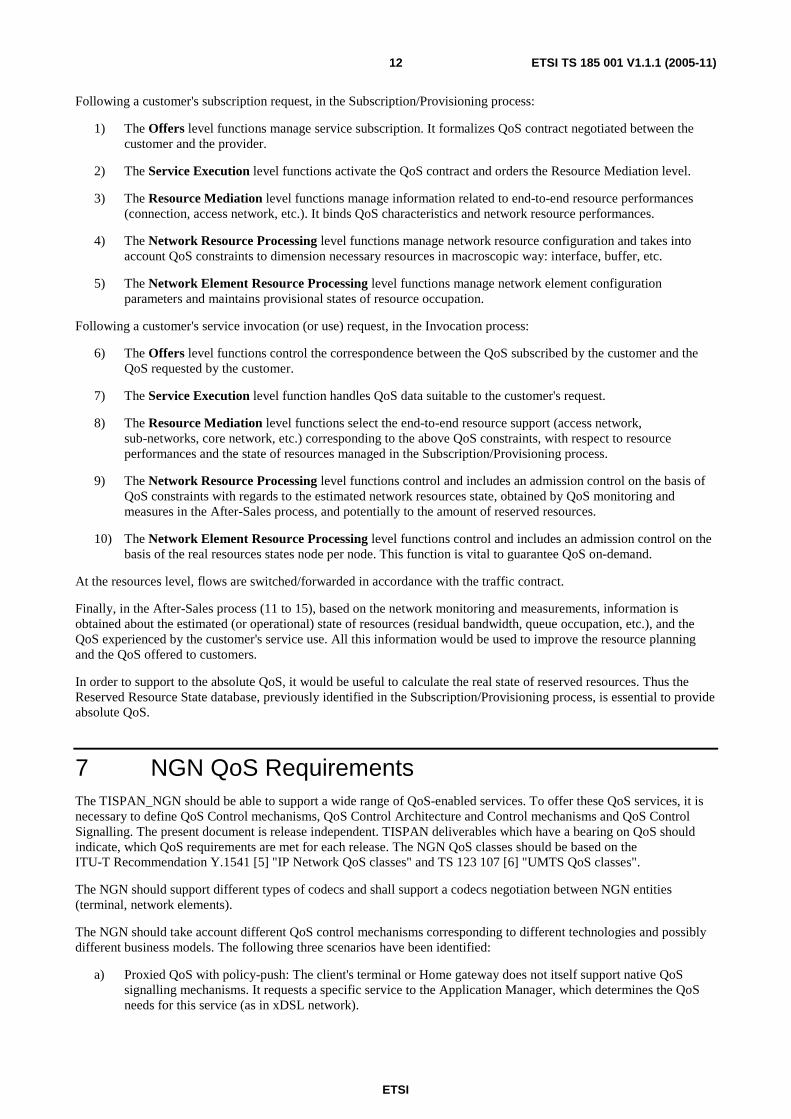
Following a customer's subscription request, in the Subscription/Provisioning process:
1) The Offers level functions manage service subscription. It formalizes QoS contract negotiated between the customer and the provider.
2) The Service Execution level functions activate the QoS contract and orders the Resource Mediation level.
3) The Resource Mediation level functions manage information related to end-to-end resource performances (connection, access network, etc.). It binds QoS characteristics and network resource performances.
4) The Network Resource Processing level functions manage network resource configuration and takes into account QoS constraints to dimension necessary resources in macroscopic way: interface, buffer, etc.
5) The Network Element Resource Processing level functions manage network element configuration parameters and maintains provisional states of resource occupation.
Following a customer's service invocation (or use) request, in the Invocation process:
6) The Offers level functions control the correspondence between the QoS subscribed by the customer and the QoS requested by the customer.
7) The Service Execution level function handles QoS data suitable to the customer's request.
8) The Resource Mediation level functions select the end-to-end resource support (access network, sub-networks, core network, etc.) corresponding to the above QoS constraints, with respect to resource performances and the state of resources managed in the Subscription/Provisioning process.
9) The Network Resource Processing level functions control and includes an admission control on the basis of QoS constraints with regards to the estimated network resources state, obtained by QoS monitoring and measures in the After-Sales process, and potentially to the amount of reserved resources.
10) The Network Element Resource Processing level functions control and includes an admission control on the basis of the real resources states node per node. This function is vital to guarantee QoS on-demand.
At the resources level, flows are switched/forwarded in accordance with the traffic contract.
Finally, in the After-Sales process (11 to 15), based on the network monitoring and measurements, information is obtained about the estimated (or operational) state of resources (residual bandwidth, queue occupation, etc.), and the QoS experienced by the customer's service use. All this information would be used to improve the resource planning and the QoS offered to customers.
In order to support to the absolute QoS, it would be useful to calculate the real state of reserved resources. Thus the Reserved Resource State database, previously identified in the Subscription/Provisioning process, is essential to provide absolute QoS.
7 NGN QoS Requirements The TISPAN_NGN should be able to support a wide range of QoS-enabled services. To offer these QoS services, it is necessary to define QoS Control mechanisms, QoS Control Architecture and Control mechanisms and QoS Control Signalling. The present document is release independent. TISPAN deliverables which have a bearing on QoS should indicate, which QoS requirements are met for each release. The NGN QoS classes should be based on the ITU-T Recommendation Y.1541 [5] "IP Network QoS classes" and TS 123 107 [6] "UMTS QoS classes".
The NGN should support different types of codecs and shall support a codecs negotiation between NGN entities (terminal, network elements).
The NGN should take account different QoS control mechanisms corresponding to different technologies and possibly different business models. The following three scenarios have been identified:
a) Proxied QoS with policy-push: The client's terminal or Home gateway does not itself support native QoS signalling mechanisms. It requests a specific service to the Application Manager, which determines the QoS needs for this service (as in xDSL network).
ETSI
ETSI TS 185 001 V1.1.1 (2005-11) 13
b) User-requested QoS with policy-push: The client is able to request its QoS needs and the terminal or the Home gateway is capable to send QoS requests over signalling and/or management protocols for its own QoS needs, but requires prior authorization from an Application Manager (as in Mobile Network).
c) User-requested QoS with policy-pull: The user's terminal or Home gateway is capable of sending QoS Request over signalling and management protocols for its own QoS needs, and does not require prior authorization.
The NGN QoS architecture should be able to manage different types of access network (e.g. xDSL, 3GPP access network, etc.).
The NGN QoS Control Signalling should be based on already defined protocols or protocols under development (e.g. RSVP, COPS, NSIS, etc.).
8 QoS Classes The standardization work traditionally distinguishes between teleservices, which operated across terminals and networks (e.g. mouth-ear for voice) and bearer services that excluded terminals (from UNI to UNI). In an opened and deregulated market, it is not always possible to control the user's domestic installation. Previously, the QoS specifications have been focused on end-to-end QoS. But in an NGN environment, the network performance at the bearer service level should be taken into account.
The NGN QoS classes should be based on the ITU-T Recommendation Y.1541 [5] "IP Network QoS classes" and TS 123 107 [6] "UMTS QoS classes".
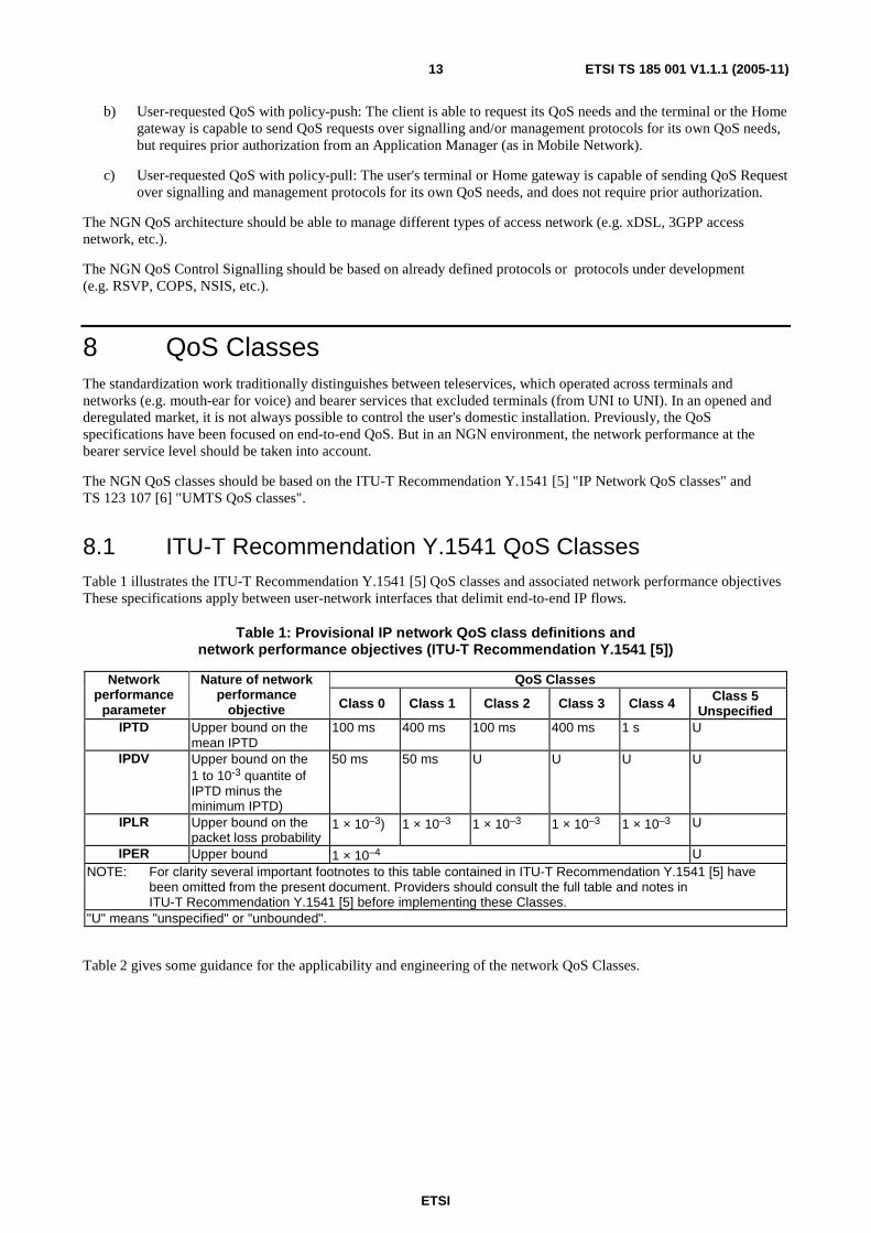
8.1 ITU-T Recommendation Y.1541 QoS Classes Table 1 illustrates the ITU-T Recommendation Y.1541 [5] QoS classes and associated network performance objectives These specifications apply between user-network interfaces that delimit end-to-end IP flows.
Table 1: Provisional IP network QoS class definitions and network performance objectives (ITU-T Recommendation Y.1541 [5])
QoS Classes Network performance
parameter
Nature of network performance
objective Class 0 Class 1 Class 2 Class 3 Class 4 Class 5 Unspecified
IPTD Upper bound on the mean IPTD
100 ms 400 ms 100 ms 400 ms 1 s U
IPDV Upper bound on the 1 to 10-3 quantite of IPTD minus the minimum IPTD)
50 ms 50 ms U U U U
IPLR Upper bound on the packet loss probability
1 × 10⁻³) 1 × 10⁻³ 1 × 10⁻³ 1 × 10⁻³ 1 × 10⁻³ U
IPER Upper bound 1 × 10⁻⁴ U NOTE: For clarity several important footnotes to this table contained in ITU-T Recommendation Y.1541 [5] have
been omitted from the present document. Providers should consult the full table and notes in ITU-T Recommendation Y.1541 [5] before implementing these Classes.
"U" means "unspecified" or "unbounded".
Table 2 gives some guidance for the applicability and engineering of the network QoS Classes.
ETSI
ETSI TS 185 001 V1.1.1 (2005-11) 14
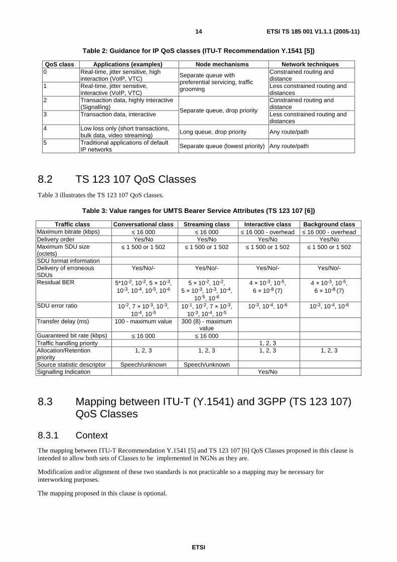
Table 2: Guidance for IP QoS classes (ITU-T Recommendation Y.1541 [5])
QoS class Applications (examples) Node mechanisms Network techniques 0 Real-time, jitter sensitive, high
interaction (VoIP, VTC) Constrained routing and distance
1 Real-time, jitter sensitive, interactive (VoIP, VTC)
Separate queue with preferential servicing, traffic grooming Less constrained routing and
distances 2 Transaction data, highly interactive
(Signalling) Constrained routing and distance
3 Transaction data, interactive Separate queue, drop priority
Less constrained routing and distances
4 Low loss only (short transactions, bulk data, video streaming)
Long queue, drop priority Any route/path
5 Traditional applications of default IP networks Separate queue (lowest priority) Any route/path
8.2 TS 123 107 QoS Classes Table 3 illustrates the TS 123 107 QoS classes.
Table 3: Value ranges for UMTS Bearer Service Attributes (TS 123 107 [6])
Traffic class Conversational class Streaming class Interactive class Background class Maximum bitrate (kbps) ≤ 16 000 ≤ 16 000 ≤ 16 000 - overhead ≤ 16 000 - overhead Delivery order Yes/No Yes/No Yes/No Yes/No Maximum SDU size (octets)
≤ 1 500 or 1 502 ≤ 1 500 or 1 502 ≤ 1 500 or 1 502 ≤ 1 500 or 1 502
SDU format information Delivery of erroneous SDUs
Yes/No/- Yes/No/- Yes/No/- Yes/No/-
Residual BER 5*10-2, 10-2, 5 × 10⁻³, 10-3, 10-4, 10-5, 10-6
5 × 10⁻², 10-2, 5 × 10⁻³, 10-3, 10-4,
10-5, 10-6
4 × 10⁻³, 10-5, 6 × 10⁻⁸ (7)
4 × 10⁻³, 10-5, 6 × 10⁻⁸ (7)
SDU error ratio 10-2, 7 × 10⁻³, 10-3, 10-4, 10-5
10-1, 10-2, 7 × 10⁻³, 10-3, 10-4, 10-5
10-3, 10-4, 10-6 10-3, 10-4, 10-6
Transfer delay (ms) 100 - maximum value 300 (8) - maximum value
Guaranteed bit rate (kbps) ≤ 16 000 ≤ 16 000 Traffic handling priority 1, 2, 3 Allocation/Retention priority
1, 2, 3 1, 2, 3 1, 2, 3 1, 2, 3
Source statistic descriptor Speech/unknown Speech/unknown Signalling Indication Yes/No
8.3 Mapping between ITU-T (Y.1541) and 3GPP (TS 123 107) QoS Classes
8.3.1 Context
The mapping between ITU-T Recommendation Y.1541 [5] and TS 123 107 [6] QoS Classes proposed in this clause is intended to allow both sets of Classes to be implemented in NGNs as they are.
Modification and/or alignment of these two standards is not practicable so a mapping may be necessary for interworking purposes.
The mapping proposed in this clause is optional.
ETSI
ETSI TS 185 001 V1.1.1 (2005-11) 15
8.3.2 Hypothesis
This clause describes a QoS mapping (in each direction) between two networks: a 3GPP network providing UMTS service in accordance with the TS 123 107 QoS classes and bearer service attributes, and an IP network supporting assured-quality IP flows in accordance with ITU-T Recommendation Y.1541 [5].
For simplicity, the UMTS SDU is assumed to correspond to an IP packet.
The end-to-end IP packet transfer service provided by the networks is intended to meet the end-to-end QoS objectives of ITU-T Recommendation Y.1541 [5]. The objective in mapping QoS classes (and bearer attribute values) between the UMTS network and the IP network is to divide the end-to end "impairment budget" for each ITU-T Recommendation Y.1541 [5] performance parameter (delay, delay variation, packet loss, packet error) appropriately between them. An equal division is assumed, e.g. each network would get 50 ms of a 100 ms end-to-end IPTD objective.
A QoS translator in the interworking function between the UMTS network and the IP network maps QoS classes and attribute values between the two networks so as to ensure, where possible, that the end-to-end QoS objectives are met.
8.3.3 Y.1541 to TS 123 107
The QoS translator maps Y.1541 class 0 to the UMTS conversational class, selecting the 10-4 value for the SDU error ratio attribute. The UMTS SDU transfer delay value (100 ms maximum) may or may not meet the example objective for the UMTS network portion (50 ms mean), depending on the SDU transfer delay distribution. The UMTS SDU error ratio value (10-4) meets the Y.1541 IPLR and IPER objectives assumed for the UMTS network portion (5 × 10⁻⁴, 5 × 10⁻⁵), since the former parameter definition combines the Y.1541 packet loss and packet error outcomes. The UMTS conversational class requirement to 'preserve time relation (variation) between information entities of the stream' relates qualitatively to the Y.1541 IPDV objective, but the end-to-end objective is not assured since the UMTS specification does not currently limit IPDV.
ITU-T Recommendation Y.1541 [5] class 1 is mapped to the UMTS streaming class, selecting the 10-4 SDU error ratio value. The UMTS SDU transfer delay value (300 ms maximum) might or might not meet the example objective for the UMTS network portion (200 ms mean), depending on the delay distribution. The UMTS SDU error ratio value meets the example Y.1541 IPLR and IPER objectives as described for class 0 above. The Y.1541 IPDV objective is addressed qualitatively but without end-to-end assurance as noted above.
ITU-T Recommendation Y.1541 [5] classes 2 to 4 is mapped to the UMTS interactive class with a 10-4 SDU error ratio. The three Y.1541 classes are mapped to different UMTS interactive class priority levels to reflect their different IPTD objectives; but as noted in TS 123 107 [6], these relative priorities may not provide assured quality levels. If more assured IPTD values are required, ITU-T Recommendation Y.1541 [5] classes 2 to 4 can be mapped to the UMTS conversational or streaming class. The SDU transfer delay limit of the UMTS conversational class (100 ms maximum) may or may not meet the example IPTD objective of class 2 (50 ms mean); it definitely meets the assumed IPTD objectives of classes 3 and 4 (200 ms and 500 ms mean, respectively). Similarly, the SDU transfer delay limit of the UMTS streaming class (300 ms maximum) may or may not meet the assumed IPTD objectives of classes 2 and 3 (50 ms and 200 ms mean respectively), but definitely meets the assumed IPTD objective of class 4 (500 ms mean).
ITU-T Recommendation Y.1541 [5] class 5 is mapped to the UMTS background class.
The mappings suggested above are probably the most reasonable ones, and they could meet the postulated IPLR and IPER requirements for all of theY.1541 classes. The suggested mappings do not meet the end-to-end delay requirements for some classes, and, as noted, place no quantitative bounds on end-to-end IPDV.
8.3.4. TS 123 107 to Y.1541
The mapping from UMTS QoS classes to Y.1541 QoS classes essentially reverses that described in previous clause. The UMTS conversational class is mapped to Y.1541 class 0. The UMTS streaming class is mapped to Y.1541 class 1. The UMTS interactive class can be mapped to Y.1541 class 2, 3 or 4 depending on the specified traffic handling priority; the Y.1541 classes provide quantitative limits supporting up to three priority levels. The UMTS background class is mapped to Y.1541 class 5.
These mappings do not meet the end-to-end delay requirements for some classes and place no quantitative bounds on end-to-end IPDV.

ETSI
ETSI TS 185 001 V1.1.1 (2005-11) 16
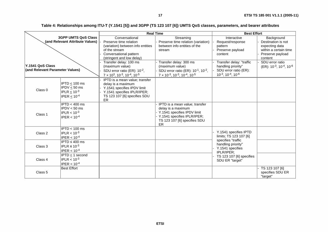
Table 4 summaries the Relationships among ITU-T Recommendation Y.1541 [5] and TS 123 107 [6] UMTS QoS classes, parameters, and bearer attributes.
ETSI
ETSI TS 185 001 V1.1.1 (2005-11) 17
Table 4: Relationships among ITU-T (Y.1541 [5]) and 3GPP (TS 123 107 [6]) UMTS QoS classes, parameters, and bearer attributes
Real Time Best Effort Conversational
- Preserve time relation (variation) between info entities of the stream
- Conversational pattern (stringent and low delay)
Streaming - Preserve time relation (variation)
between info entities of the stream
Interactive - Request/response
pattern - Preserve payload
content
Background - Destination is not
expecting data within a certain time
- Preserve payload content
3GPP UMTS QoS Class
(and Relevant Attribute Values)
Y.1541 QoS Class (and Relevant Parameter Values)
- Transfer delay: 100 ms (maximum value)
- SDU error ratio (ER): 10-2, 7 × 10³, 10-3, 10-4, 10-5
- Transfer delay: 300 ms (maximum value)
- SDU error ratio (ER): 10-1, 10-2, 7 × 10⁻³, 10-3, 10-4, 10-5
- Transfer delay: "traffic handling priority"
- SDU error ratio (ER): 10-3, 10-4, 10-6
- SDU error ratio (ER): 10-3, 10-4, 10-6
Class 0
IPTD < 100 ms IPDV < 50 ms IPLR < 10-3
IPER < 10-4
- IPTD is a mean value; transfer delay is a maximum
- Y.1541 specifies IPDV limit - Y.1541 specifies IPLR/IPER;
TS 123 107 [6] specifies SDU ER
Class 1
IPTD < 400 ms IPDV < 50 ms IPLR < 10-3 IPER < 10-4
- IPTD is a mean value; transfer delay is a maximum
- Y.1541 specifies IPDV limit - Y.1541 specifies IPLR/IPER;
TS 123 107 [6] specifies SDU ER
Class 2 IPTD < 100 ms IPLR < 10-3 IPER < 10-4
Class 3 IPTD ≤ 400 ms IPLR ≤ 10-3 IPER < 10-4
Class 4 IPTD < 1 second IPLR < 10-3 IPER < 10-4
- Y.1541 specifies IPTD limits; TS 123 107 [6] specifies "traffic handling priority"
- Y.1541 specifies IPLR/IPER;
- TS 123 107 [6] specifies SDU ER "target"
Class 5 Best Effort - TS 123 107 [6]
specifies SDU ER "target"
ETSI
ETSI TS 185 001 V1.1.1 (2005-11) 18
8.3.5 Limitations
The most problematic limitation for this mapping is the transfer delay. Transfer delay specifications are not translatable between the two recommendations as ITU-T Recommendation Y.1541 [5] specifies IPTD as a mean value, while TS 123 107 [6] specifies SDU transfer delay as a maximum. IPDV cannot currently be limited end-to-end because the UMTS specification does not define or quantitatively limit delay variation.
The translations are more complicated in situations where the SDU and IP packet sizes substantially differ.
9 Codecs As the NGN should be open to the different networks (PSTN, UMTS, IP Network), the following principles define the use of audio and video codecs:
1) The NGN should support different types of codecs. It is recognized that some codecs play an important role in existing and emerging networks for audio and video services.
EXAMPLE: ITU-T Recommendation G.711 [7] in circuit switched oriented networks, ITU-T Recommendation G.729 [8] in packet-based networks, AMR (and WB-AMR for Wideband telephony) in 3G UMTS networks.
2) The NGN shall support a wide and open list of codecs negotiation between NGN entities (terminal, network elements).
3) If needed, audio transcoding is performed to ensure end-to-end service interoperability. This may be performed for example by Residential or Home Gateways in customer premises, in Access, Media or Network Interconnect Gateways depending on the communication configuration.
4) Transcoding should be avoided wherever possible.
10 QoS Scenarios In NGN, different QoS control mechanisms could be used, corresponding to different technologies and possibly different business models. Those QoS support mechanisms have a strong influence on the architecture that may be needed to provide them. As a matter of fact, there exists several different alternatives, depending for instance on user terminal capabilities or on service needs.
Three main scenarios can be identified from the viewpoint of the user terminal:
1) Proxied QoS with policy-push: The user terminal or the home gateway does not itself support native QoS signalling mechanisms. It requests a specific service to the Service controller, which determines the QoS needs for this service (as in xDSL network).
2) User-requested QoS with policy-push-pull: The user terminal or the home gateway is able to send explicit QoS requests for its own QoS needs, but before doing this, prior authorization from the Service controller is required (as in Mobile network).
3) User-requested QoS with policy-pull: The user's terminal or Home gateway is capable of sending QoS Request over signalling and management protocols for its own QoS needs using a Layer 3 QoS signalling protocol for its own QoS needs. The authorization for the QoS request is performed by the network on receipt of that request without prior authorization.
Irrespective of the mechanism used to request QoS from the terminal, there exist several mechanisms to propagate QoS requests in a network and across network.
ETSI
ETSI TS 185 001 V1.1.1 (2005-11) 19
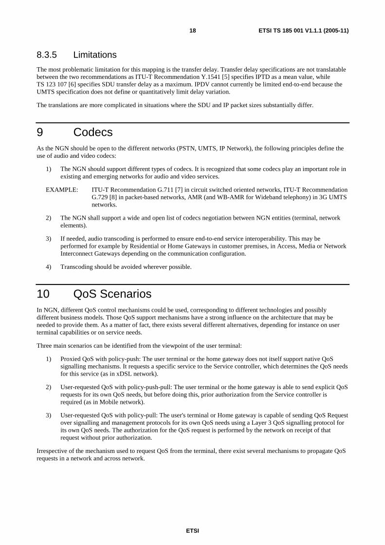
10.1 Scenario 1 - Proxied QoS with policy-push In the "Proxied QoS with policy-push" scenario, the user terminal or home gateway does not itself support native QoS signalling mechanisms. It requests an application-specific service by sending a "Service Request" to the Service controller. It is then the Service controller's responsibility to determine the QoS needs of the requested service, to request network authorization from the Network Resource Controller which then requests resource reservation to Core network and to Access network.
A flow diagram for this scenario is provided in figure 4. For clarity, the flow diagrams do not show any ack/confirmation.
Access networkCore network
NGN Transport Layer
NGN Service Layer
Core network
Service controller
NGN access domain NGN core domain #1 NGN core domain #2CPN NNIUNI NNI NNI
Service controller 1. Service Request
1bis. Service Request
2. Resource Request
3. Resource Reservation
RACS
Figure 4: Scenario 1 - Proxied QoS with policy-push
This scenario does not require any resource reservation signalling capabilities on the user terminal and does not recommend any protocol for the service session requests. It is required to always go through the Service controller for any service request, including bandwidth reservation changes during a session.
This scenario 1 supports single-phase resource reservation or two-phase resource reservation.
• In the first case, the network enables immediate activation and usage of network resources by the end-user.
• In the second case, the Service controller first asks for network QoS resources to be authorized and reserved. Once these resources have been reserved, the Service controller continues its dialogue with the user concerning the service. This two-phase reserve/commit model guarantees that access-network resources are available before offering service to the user and can also help protect against unauthorized use of service.
In current xDSL networks, the QoS management is in conformance with this scenario 1.
ETSI
ETSI TS 185 001 V1.1.1 (2005-11) 20
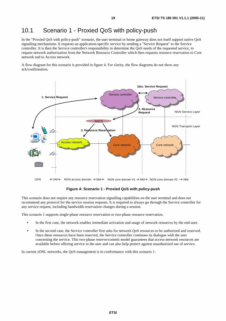
10.2 Scenario 2 - User-requested QoS with policy-push-pull In scenario 2, "User-requested QoS with policy-push-pull", the user terminal or home gateways is capable of signalling and managing its own QoS resources but requires prior authorization of these requests via the Service controller. It requests an application-specific service by sending a "Service Request" to the Service controller. The Service controller is in charge of determining the QoS needs of the requested service and of requesting the network authorization from the Network resource controller. The Service Controller may relay to the end-user an associated Authorization token. Then, the terminal uses a specific signalling to request resource reservation (and commitment), for example a Layer 3 QoS signalling mechanism. The authorization token may be included in the QoS signalling request in order to facilitate authorization of the QoS request. This request could be managed in the Access Network with authorization of the Network Resource Controller (as in UMTS) or directly by the Network Resource Controller.
A flow diagram for this scenario is provided in figure 5.
This scenario has the ability to establish QoS reservation end-to-end since the IP QoS signalling proceeds on-path end-to-end and thus can be used (if desired) at any step along the end-to-end path (e.g. in Access network, in Core network, in subsequent core networks, in remote access networks, etc.), and allow multi-homing access which increases resiliency.
It requires supporting a Layer 3 QoS signalling capability on the user terminal.
Access networkCore network
NGN Transport Layer
NGN Service Layer
Core network
Service controller
NGN access domain NGN core domain #1 NGN core domain #2CPN NNIUNI NNI NNI
Service controller 1. Service Request
1bis. Service Request
4. QoS Authorization
3. QoS Signalling
RACS
2. Policy enforcement
5. Resource Reservation
Figure 5: Scenario 2 - User-requested QoS with policy-push-pull
10.3 Scenario 3 - User-requested QoS with policy-pull The user's terminal or Home gateway is capable of sending QoS Request over signalling and management protocols for its own QoS needs, and does not require prior authorization. The user's terminal or Home gateway is capable of sending QoS Request over Layer 3 QoS signalling for its own QoS needs. Authorization for the QoS request is obtained 'on the fly' at the time where the QoS request is actually signalled. Unlike in Scenario 2, no communications with the Service Controller is needed prior to making the QoS request to obtain the corresponding authorization .
A flow diagram for this scenario is provided in figure 6.

ETSI
ETSI TS 185 001 V1.1.1 (2005-11) 21
This scenario does not require any communications with the Service Controller (in particular to obtain prior authorization for each QoS request), to avoid the need for the Network Resource Controller to maintain awareness of the relationship between end-users and their corresponding Policy Enforcement Functions, and to allow multi-homing access which increases resiliency. It is able to establish QoS reservation end-to-end since the IP QoS signalling proceeds on-path end-to-end and thus can be used (if desired) at any step along the end-to-end path (e.g. in Access network, in Core network, in subsequent core networks, at the boundary between core networks, in remote access networks, etc.).
It requires supporting a Layer 3 QoS signalling capability on the user terminal.
Access networkCore network
NGN Transport Layer
NGN Service Layer
Core network
NGN access domain NGN core domain #1 NGN core domain #2CPN NNIUNI NNI NNI
Service controller
2. QoS Authorization
1. QoS Signalling
RACS
3. Resource Reservation
Figure 6: Scenario 3 - User-requested QoS with policy-pull
11 QoS Architecture Requirements
11.1 Architectural requirements The NGN QoS architecture should be able to manage different types of access network (xDSL, 3GPP access network, etc.) and different types of core networks, which could be in the same administrative domain or in different administrative domains.
The NGN QoS Architecture should support the following requirements:
1) Support functions for QoS resource reservation, admission control service based local policy, network policy control and gate control.
2) Provide a mechanism to Application Functions in different multimedia service subsystems to reserve resources in the access transport and the core transport.
3) Support resource and admission control across multiple administrative domains.
4) Support the three QoS scenarios defined in clause 9, namely "Proxied QoS with policy-push", "User-requested QoS with policy-push" and "User-requested QoS with policy-pull".
5) Support both guaranteed QoS control and relative QoS control.
ETSI
ETSI TS 185 001 V1.1.1 (2005-11) 22
6) Support different access transport technologies, including xDSL, UMTS, Cable, LAN, WLAN, Ethernet, MPLS, IP, ATM, etc.
7) Support different core transport technologies.
8) Be able to export charging information and session metrics.
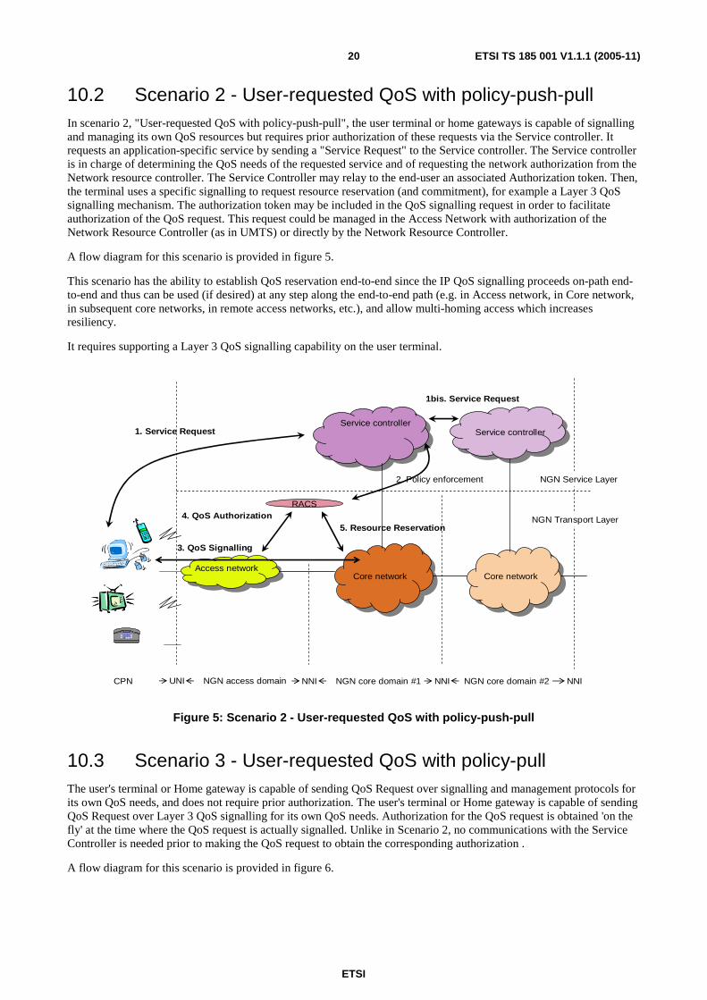
11.2 QoS architecture The QoS architecture describes in figure 7 support the previous requirements.
SPDF
NCRP
NGN Service stratum
NGN Transport stratum
Application Functions
CCRP
Other dom
ains
Core RACF 2
Core RACF 1
Access RACF n
Access RACF 1
SCRP SCRP
SCRP SCRP
NCRP CPE
Access Transport Functions
Core Transport Functions
Figure 7: QoS architecture
The main component that manages QoS in NGN is the SPDF (Service Policy Decision Functions) and the RACF (Resource and Admission Control Functions).
The SPDF makes policy decisions using policy rules and communicates these decisions to the RACF.
The SPDF provides mediation between one or many Service Providers and one or many Network Resource Providers. The SPDF provides an abstract view of the transport functions to the content or application services.
Its main advantage in the NGN architecture is to simplify and fasten the development of services by Service Providers. It also allows enforcing a clear separation between service-related functions and transport-related technologies as requested for the NGN.
The SPDF acts as intermediary between service execution and resource processing. It first ensures the adaptation between service instance and resources by translating service parameters into resource parameters. This mediation is then in charge of resource positioning in order to support the customer's service.
The SPDF is in charge of determining which Network Resource Providers should be involved in the support of a given service. It will then interact with each of them to obtain the necessary resources for the service.
The SPDF makes the Resource Processing independent from the Service Processing.
The functions includes in SPDF could evolve with the TISPAN Releases.
ETSI
ETSI TS 185 001 V1.1.1 (2005-11) 23
The RACF receives requests for QoS resources from the SPDF indicating QoS characteristics (e.g. bandwidth). The RACF shall use the QoS information received from the SPDF to perform admission control, i.e. the RACF checks whether the requested QoS resources can be made available for the involved access. The RACF shall indicate to the SPDF whether a request for resources is granted or not.
Two types of RACF should exist:
• Access RACF (A-RACF).
• Core RACF (C-RACF).
Different instances of RACF could exist, both for A-RACF and C-RACF, depending of the network architecture. As the core network could involve different domains and different core network providers, each core network should have its own Core RACF. The NGN takes into account different types of access networks (e.g. Mobile network, DSL network, etc.). Each of these networks has it own characteristics and could also be managed by a specific provider. Each of these providers should have his own Access RACF.
Three reference points are defined:
• CCRP: Call/Connection Control Reference Point;
• NCRP: Network Control Reference Point;
• SCRP: Switch Control Reference Point.
12 QoS Signalling Requirements
12.1 QoS Signalling Requirements in Call/Connection Control Reference Point
The QoS signalling between the Service stratum and the RACS of Transport stratum on Call/Connection Control Reference Point should accomplish the following functions:
• Request for resources:
- Service stratum initiates a QoS request to the RACS of Transport Stratum.
• Modification of the request:
- In respect with some services, it may be necessary to modify the QoS requirements at anytime during the service running. According to Service stratum requirements, RACS of Transport Stratum modifies the bandwidth it applied for use last time. Multi-time modification is supported.
• Resource status report:
- In case of any change with the allocated resources (e.g. the resource seized by the connection is no longer available), the Transport Stratum should report it to the Service stratum.
• Release of resources to support service:
- When a service is terminated, the Service stratum should initiate a request to RACS of Transport Stratum for releasing the resource that has been requested to allocate.

ETSI
ETSI TS 185 001 V1.1.1 (2005-11) 24
12.2 QoS Signalling Requirements in Network Control Reference Point
For dynamic negotiation of QoS between service and access providers, as well as between service providers, a mechanism based on SLAs shall be provided.
Optionally, QoS signalling over the Network Control Reference Point (NCRP) may be provided, depending on the interconnection schemes and agreements. The following basic functions should be accomplished in such case:
• Request for resources.
• Modification of request.
• Resource status report (for reporting changes in the status of the allocated resources).
• Release of resources.
12.3 QoS Signalling Requirements in Switch Control Reference Point
Since the Switch Control Reference Point (SCRP) carries the configuration information related to QoS requests, the parameters of these messages may vary for different network layer technologies.
This reference point transports the QoS parameters after being translated into network technology dependent parameters. There are the following requirements for QoS signalling between the RACS of Transport Stratum and the Transport Functions of Transport Stratum.
• QoS configuration information delivery.
• Modification of the QoS configuration information.
• Resource status report.
• Release of QoS configuration.
ETSI
ETSI TS 185 001 V1.1.1 (2005-11) 25
Annex A (informative): List of Audio and Video Codecs for conversational applications The following list identifies the most important and widely used audio and video codecs for conversational applications and the main foreseen ones (under ongoing standardization process). It is not an exhaustive list: Regional Standards or other Codecs with more limited use are not mentioned. For instance, Codecs dedicated to specific applications like military applications, satellite transmissions for which transmission conditions are very bad are not listed (these codecs have a very limited quality and aims rather at intelligibility).
This list covers Audio Codecs in Narrow Band (300 Hz to 3 400 Hz) and in WideBand (≥7 kHz).
ETSI
ETSI TS 185 001 V1.1.1 (2005-11) 26
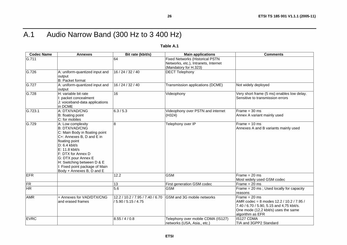
A.1 Audio Narrow Band (300 Hz to 3 400 Hz) Table A.1
Codec Name Annexes Bit rate (kbit/s) Main applications Comments G.711 64
Fixed Networks (Historical PSTN Networks, etc.), Intranets, Internet (Mandatory for H.323)
G.726 A: uniform-quantized input and output B: Packet format
16 / 24 / 32 / 40
DECT Telephony
G.727 A: uniform-quantized input and output
16 / 24 / 32 / 40
Transmission applications (DCME) Not widely deployed
G.728 H: variable bit rate I: packet concealment J: voiceband-data applications in DCME
16 Videophony Very short frame (5 ms) enables low delay. Sensitive to transmission errors
G.723.1 A: DTX/VAD/CNG B: floating point C: for mobiles
6.3 / 5.3 Videophony over PSTN and internet (H324)
Frame = 30 ms Annex A variant mainly used
G.729 A: Low complexity B: DTX/VAD/CNG C: Main Body in floating point C+: Annexes B, D and E in floating point D: 6.4 kbit/s E: 11.8 kbit/s F: DTX for Annex D G: DTX pour Annex E H: Switching between D & E I: Fixed point package of Main Body + Annexes B, D and E
8 Telephony over IP Frame = 10 ms Annexes A and B variants mainly used
EFR 12.2 GSM Frame = 20 ms Most widely used GSM codec
FR 13 First generation GSM codec Frame = 20 ms HR 5.6 GSM Frame = 20 ms ; Used locally for capacity
reasons AMR + Annexes for VAD/DTX/CNG
and erased frames 12.2 / 10.2 / 7.95 / 7.40 / 6.70 / 5.90 / 5.15 / 4.75
GSM and 3G mobile networks Frame = 20 ms AMR codec = 8 modes 12.2 / 10.2 / 7.95 / 7.40 / 6.70 / 5.90, 5.15 and 4,75 kbit/s. One mode (12,2 kbit/s) uses the same algorithm as EFR
EVRC 8.55 / 4 / 0.8 Telephony over mobile CDMA (IS127) networks (USA, Asia., etc.)
IS127 CDMA TIA and 3GPP2 Standard
ETSI
ETSI TS 185 001 V1.1.1 (2005-11) 27
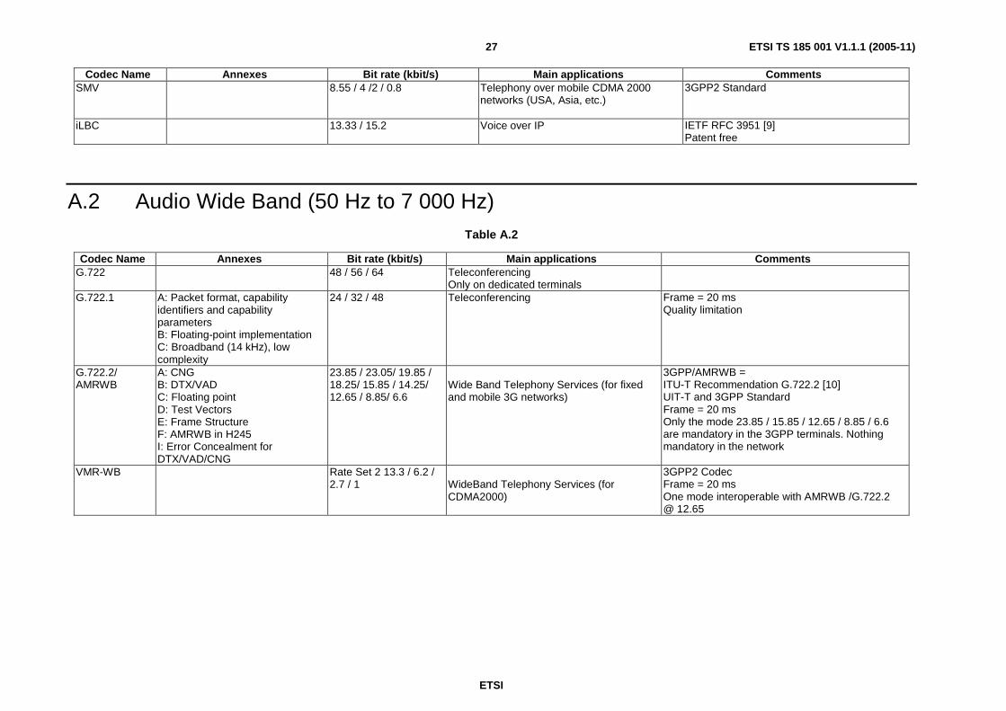
Codec Name Annexes Bit rate (kbit/s) Main applications Comments SMV 8.55 / 4 /2 / 0.8 Telephony over mobile CDMA 2000
networks (USA, Asia, etc.)
3GPP2 Standard
iLBC 13.33 / 15.2 Voice over IP IETF RFC 3951 [9] Patent free
A.2 Audio Wide Band (50 Hz to 7 000 Hz) Table A.2
Codec Name Annexes Bit rate (kbit/s) Main applications Comments G.722 48 / 56 / 64 Teleconferencing
Only on dedicated terminals
G.722.1 A: Packet format, capability identifiers and capability parameters B: Floating-point implementation C: Broadband (14 kHz), low complexity
24 / 32 / 48 Teleconferencing Frame = 20 ms Quality limitation
G.722.2/ AMRWB
A: CNG B: DTX/VAD C: Floating point D: Test Vectors E: Frame Structure F: AMRWB in H245 I: Error Concealment for DTX/VAD/CNG
23.85 / 23.05/ 19.85 / 18.25/ 15.85 / 14.25/ 12.65 / 8.85/ 6.6
Wide Band Telephony Services (for fixed and mobile 3G networks)
3GPP/AMRWB = ITU-T Recommendation G.722.2 [10] UIT-T and 3GPP Standard Frame = 20 ms Only the mode 23.85 / 15.85 / 12.65 / 8.85 / 6.6 are mandatory in the 3GPP terminals. Nothing mandatory in the network
VMR-WB Rate Set 2 13.3 / 6.2 / 2.7 / 1
WideBand Telephony Services (for CDMA2000)
3GPP2 Codec Frame = 20 ms One mode interoperable with AMRWB /G.722.2 @ 12.65
ETSI
ETSI TS 185 001 V1.1.1 (2005-11) 28
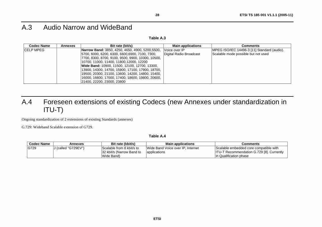
A.3 Audio Narrow and WideBand Table A.3
Codec Name Annexes Bit rate (bit/s) Main applications Comments CELP MPEG Narrow Band: 3850, 4250, 4650, 4900, 5200,5500,
5700, 6000, 6200, 6300, 6600,6900, 7100, 7300, 7700, 8300, 8700, 9100, 9500, 9900, 10300, 10500, 10700, 11000, 11400, 11800,12000, 12200 Wide Band: 10900, 11500, 12100, 12700, 13300, 13900, 14300, 14700, 15900, 17100, 17900, 18700, 19500, 20300, 21100, 13600, 14200, 14800, 15400, 16000, 16600, 17000, 17400, 18600, 19800, 20600, 21400, 22200, 23000, 23800
Voice over IP Digital Radio Broadcast
MPEG ISO/IEC 14496-3 [11] Standard (audio). Scalable mode possible but not used
A.4 Foreseen extensions of existing Codecs (new Annexes under standardization in ITU-T)
Ongoing standardization of 2 extensions of existing Standards (annexes)
G.729: Wideband Scalable extension of G729.
Table A.4
Codec Name Annexes Bit rate (kbit/s) Main applications Comments G729 J (called "G729EV") Scalable from 8 kbit/s to
32 kbit/s (Narrow Band to Wide Band)
Wide Band Voice over IP, Internet applications
Scalable embedded core compatible with ITU-T Recommendation G.729 [8]. Currently in Qualification phase

ETSI
ETSI TS 185 001 V1.1.1 (2005-11) 29
A.5 Video Table A.5
Codec Name Annexes Main applications Comments
H.261 Standardized codec for H.320(ISDN)/H.323 videotelephony
H.263 profile 0 level 10(QCIF-64 kbps max) to level 70 (720x576 – 16 384 kbit/s max)
Standardized codec for H.323/H.324/SIP videotelephony. Used in MMS, streaming and broadcast services in 3GPP services
Mandatory in 3GPP conversational and MMS services until release 6
H.263 Profile 3 (H.263+) level 10(QCIF-64 kbps max) to level 70(720x576 – 16 384 kbit/s max)
Standardized codec for H.323/H.324/SIP videotelephony. Used in MMS, streaming and broadcast services in 3GPP services
Optional in 3GPP conversational and mms services until release 6 Better error-robustness and subjective quality than profile 0
MPEG4 visual Simple Profile Level 0 H.264 Baseline profile, Baseline compatible
main profile Standardized codec for H.323/H.324/SIP videotelephony. Introduced in MMS, streaming and broadcast services in 3GPP services
Equal quality to ITU-T Recommendation H.263 [12] at half of the H.263 bitrate. Improve error-resilience capacity. Introduced in 3GPP services for release 6
ITU Standardization: ITU-T Recommendation H.264+ [13] (a lot of work items like reducing complexity, etc.)

ETSI
ETSI TS 185 001 V1.1.1 (2005-11) 30
History
Document history
V1.1.1 November 2005 Publication