ts 136 141 - v14.3.0 - lte; evolved universal terrestrial ... · etsi 3gpp ts 36.141 version 14.3.0...
TRANSCRIPT

ETSI TS 136 141 V14.3.0 (2017-04)
LTE; Evolved Universal Terrestrial Radio Access (E-UTRA);
Base Station (BS) conformance testing (3GPP TS 36.141 version 14.3.0 Release 14)
TECHNICAL SPECIFICATION

ETSI
ETSI TS 136 141 V14.3.0 (2017-04)13GPP TS 36.141 version 14.3.0 Release 14
Reference RTS/TSGR-0436141ve30
Keywords LTE
ETSI
650 Route des Lucioles F-06921 Sophia Antipolis Cedex - FRANCE
Tel.: +33 4 92 94 42 00 Fax: +33 4 93 65 47 16
Siret N° 348 623 562 00017 - NAF 742 C
Association à but non lucratif enregistrée à la Sous-Préfecture de Grasse (06) N° 7803/88
Important notice
The present document can be downloaded from: http://www.etsi.org/standards-search
The present document may be made available in electronic versions and/or in print. The content of any electronic and/or print versions of the present document shall not be modified without the prior written authorization of ETSI. In case of any
existing or perceived difference in contents between such versions and/or in print, the only prevailing document is the print of the Portable Document Format (PDF) version kept on a specific network drive within ETSI Secretariat.
Users of the present document should be aware that the document may be subject to revision or change of status. Information on the current status of this and other ETSI documents is available at
https://portal.etsi.org/TB/ETSIDeliverableStatus.aspx
If you find errors in the present document, please send your comment to one of the following services: https://portal.etsi.org/People/CommiteeSupportStaff.aspx
Copyright Notification
No part may be reproduced or utilized in any form or by any means, electronic or mechanical, including photocopying and microfilm except as authorized by written permission of ETSI.
The content of the PDF version shall not be modified without the written authorization of ETSI. The copyright and the foregoing restriction extend to reproduction in all media.
© European Telecommunications Standards Institute 2017.
All rights reserved.
DECTTM, PLUGTESTSTM, UMTSTM and the ETSI logo are Trade Marks of ETSI registered for the benefit of its Members. 3GPPTM and LTE™ are Trade Marks of ETSI registered for the benefit of its Members and
of the 3GPP Organizational Partners. oneM2M logo is protected for the benefit of its Members
GSM® and the GSM logo are Trade Marks registered and owned by the GSM Association.

ETSI
ETSI TS 136 141 V14.3.0 (2017-04)23GPP TS 36.141 version 14.3.0 Release 14
Intellectual Property Rights IPRs essential or potentially essential to the present document may have been declared to ETSI. The information pertaining to these essential IPRs, if any, is publicly available for ETSI members and non-members, and can be found in ETSI SR 000 314: "Intellectual Property Rights (IPRs); Essential, or potentially Essential, IPRs notified to ETSI in respect of ETSI standards", which is available from the ETSI Secretariat. Latest updates are available on the ETSI Web server (https://ipr.etsi.org/).
Pursuant to the ETSI IPR Policy, no investigation, including IPR searches, has been carried out by ETSI. No guarantee can be given as to the existence of other IPRs not referenced in ETSI SR 000 314 (or the updates on the ETSI Web server) which are, or may be, or may become, essential to the present document.
Foreword This Technical Specification (TS) has been produced by ETSI 3rd Generation Partnership Project (3GPP).
The present document may refer to technical specifications or reports using their 3GPP identities, UMTS identities or GSM identities. These should be interpreted as being references to the corresponding ETSI deliverables.
The cross reference between GSM, UMTS, 3GPP and ETSI identities can be found under http://webapp.etsi.org/key/queryform.asp.
Modal verbs terminology In the present document "shall", "shall not", "should", "should not", "may", "need not", "will", "will not", "can" and "cannot" are to be interpreted as described in clause 3.2 of the ETSI Drafting Rules (Verbal forms for the expression of provisions).
"must" and "must not" are NOT allowed in ETSI deliverables except when used in direct citation.

ETSI
ETSI TS 136 141 V14.3.0 (2017-04)33GPP TS 36.141 version 14.3.0 Release 14
Contents
Intellectual Property Rights ................................................................................................................................ 2
Foreword ............................................................................................................................................................. 2
Modal verbs terminology .................................................................................................................................... 2
Foreword ........................................................................................................................................................... 15
1 Scope ...................................................................................................................................................... 16
2 References .............................................................................................................................................. 16
3 Definitions, symbols and abbreviations ................................................................................................. 17
3.1 Definitions ........................................................................................................................................................ 17
3.2 Symbols ............................................................................................................................................................ 20
3.3 Abbreviations ................................................................................................................................................... 21
4 General test conditions and declarations ................................................................................................ 23
4.1 Measurement uncertainties and Test Requirements ......................................................................................... 23
4.1.1 General ........................................................................................................................................................ 23
4.1.2 Acceptable uncertainty of Test System ....................................................................................................... 23
4.1.2.1 Measurement of transmitter .................................................................................................................. 24
4.1.2.2 Measurement of receiver ....................................................................................................................... 25
4.1.2.3 Measurement of performance requirement ........................................................................................... 31
4.1.3 Interpretation of measurement results ......................................................................................................... 37
4.2 Base station classes .......................................................................................................................................... 37
4.3 Regional requirements ...................................................................................................................................... 37
4.4 Selection of configurations for testing.............................................................................................................. 40
4.5 BS Configurations ............................................................................................................................................ 40
4.5.1 Transmit configurations .............................................................................................................................. 40
4.5.1.1 Transmission with multiple transmitter antenna connectors ................................................................. 40
4.5.2 Receive configurations ............................................................................................................................... 41
4.5.2.1 Reception with multiple receiver antenna connectors, receiver diversity ............................................. 41
4.5.3 Duplexers .................................................................................................................................................... 41
4.5.4 Power supply options .................................................................................................................................. 42
4.5.5 Ancillary RF amplifiers .............................................................................................................................. 42
4.5.6 BS with integrated Iuant BS modem .......................................................................................................... 43
4.5.7 BS using antenna arrays .............................................................................................................................. 43
4.5.7.1 Receiver tests ........................................................................................................................................ 43
4.5.7.2 Transmitter tests .................................................................................................................................... 43
4.6 Manufacturer’s declarations of regional and optional requirements ................................................................ 44
4.6.1 Operating band and frequency range .......................................................................................................... 44
4.6.2 Channel bandwidth ..................................................................................................................................... 44
4.6.3 Base station output power ........................................................................................................................... 44
4.6.4 Spurious emissions Category ...................................................................................................................... 44
4.6.5 Additional operating band unwanted emissions ......................................................................................... 45
4.6.6 Co-existence with other systems ................................................................................................................. 45
4.6.7 Co-location with other base stations ........................................................................................................... 45
4.6.8 Manufacturer's declarations of supported RF configurations ..................................................................... 45
4.6.9 NB-IoT sub-carrier spacing ........................................................................................................................ 47
4.6.10 NB-IoT power dynamic range .................................................................................................................... 47
4.7 Specified frequency range and supported channel bandwidth .......................................................................... 47
4.7.1 Base Station RF Bandwidth position for multi-carrier and/or CA testing .................................................. 48
4.7.2 Aggregated Channel Bandwidth position for Contiguous CA occupied bandwidth testing ....................... 48
4.7.3 NB-IoT testing ............................................................................................................................................ 49
4.8 Format and interpretation of tests ..................................................................................................................... 49
4.9 Applicability of requirements ........................................................................................................................... 50
4.10 Test configurations for multi-carrier and/or CA operation ............................................................................... 50
4.10.1 ETC1: Contiguous spectrum operation ....................................................................................................... 50
4.10.1.1 ETC1 generation ................................................................................................................................... 51
4.10.1.2 ETC1 power allocation ......................................................................................................................... 51

ETSI
ETSI TS 136 141 V14.3.0 (2017-04)43GPP TS 36.141 version 14.3.0 Release 14
4.10.2 ETC2: Contiguous CA occupied bandwidth ............................................................................................... 51
4.10.2.1 ETC2 generation ................................................................................................................................... 51
4.10.2.2 ETC2 power allocation ......................................................................................................................... 52
4.10.3 ETC3: Non-contiguous spectrum operation ............................................................................................... 52
4.10.3.1 ETC3 generation ................................................................................................................................... 52
4.10.3.2 ETC3 power allocation ......................................................................................................................... 52
4.10.3.24 VOID ..................................................................................................................................................... 52
4.10.4 ETC4: Multi-band test configuration for full carrier allocation .................................................................. 52
4.10.4.1 ETC4 generation ................................................................................................................................... 52
4.10.4.2 ETC4 power allocation ......................................................................................................................... 53
4.10.5 ETC5: Multi-band test configuration with high PSD per carrier ................................................................ 53
4.10.5.1 ETC5 generation ................................................................................................................................... 53
4.10.5.2 ETC5 power allocation ......................................................................................................................... 54
4.10.6 ETC6: NB-IoT standalone multi-carrier operation ..................................................................................... 54
4.10.6.1 ETC6 generation ................................................................................................................................... 54
4.10.6.2 ETC6 power allocation ......................................................................................................................... 54
4.10.7 ETC7: E-UTRA and NB-IoT standalone multi-carrier operation ............................................................... 54
4.10.7.1 ETC7 generation ................................................................................................................................... 54
4.10.7.2 ETC7 power allocation ......................................................................................................................... 55
4.10.8 ETC8: E-UTRA and NB-IoT in-band multi-carrier operation .................................................................... 55
4.10.8.1 ETC8 generation ................................................................................................................................... 55
4.10.8.2 ETC8 power allocation ......................................................................................................................... 55
4.10.9 ETC9: E-UTRA and NB-IoT guard-band multi-carrier operation .............................................................. 55
4.10.9.1 ETC9 generation ................................................................................................................................... 55
4.10.9.2 ETC9 power allocation ......................................................................................................................... 56
4.11 Applicability of test configurations .................................................................................................................. 56
4.12 Requirements for BS capable of multi-band operation .................................................................................... 61
4.13 Tests for BS capable of multi-band operation with three or more bands ......................................................... 62
5 Operating bands and channel arrangement ............................................................................................. 62
5.1 General ............................................................................................................................................................. 62
5.2 Void .................................................................................................................................................................. 62
5.3 Void .................................................................................................................................................................. 62
5.4 Void .................................................................................................................................................................. 62
5.5 Operating bands ................................................................................................................................................ 62
5.6 Channel bandwidth ........................................................................................................................................... 84
5.7 Channel arrangement ........................................................................................................................................ 89
5.7.1 Channel spacing .......................................................................................................................................... 89
5.7.1A CA Channel spacing ................................................................................................................................... 89
5.7.2 Channel raster ............................................................................................................................................. 89
5.7.3 Carrier frequency and EARFCN ................................................................................................................. 89
5.8 Requirements for contiguous and non-contiguous spectrum ............................................................................ 93
6 Transmitter characteristics ..................................................................................................................... 94
6.1 General ............................................................................................................................................................. 94
6.1.1 E-UTRA Test Models ................................................................................................................................. 94
6.1.1.1 E-UTRA Test Model 1.1 (E-TM1.1)..................................................................................................... 94
6.1.1.2 E-UTRA Test Model 1.2 (E-TM1.2)..................................................................................................... 96
6.1.1.3 E-UTRA Test Model 2 (E-TM2) .......................................................................................................... 98
6.1.1.3a E-UTRA Test Model 2a (E-TM2a) ..................................................................................................... 100
6.1.1.4 E-UTRA Test Model 3.1 (E-TM3.1)................................................................................................... 100
6.1.1.4a E-UTRA Test Model 3.1a (E-TM3.1a) ............................................................................................... 101
6.1.1.5 E-UTRA Test Model 3.2 (E-TM3.2)................................................................................................... 102
6.1.1.6 E-UTRA Test Model 3.3 (E-TM3.3)................................................................................................... 105
6.1.2 Data content of Physical channels and Signals for E-TM ......................................................................... 108
6.1.2.1 Reference signals ................................................................................................................................ 108
6.1.2.2 Primary Synchronization signal .......................................................................................................... 108
6.1.2.3 Secondary Synchronization signal ...................................................................................................... 108
6.1.2.4 PBCH .................................................................................................................................................. 108
6.1.2.5 PCFICH ............................................................................................................................................... 108
6.1.2.6 PHICH ................................................................................................................................................. 109
6.1.2.7 PDCCH ............................................................................................................................................... 109

ETSI
ETSI TS 136 141 V14.3.0 (2017-04)53GPP TS 36.141 version 14.3.0 Release 14
6.1.2.8 PDSCH ................................................................................................................................................ 109
6.1.3 NB-IoT Test Model .................................................................................................................................. 110
6.1.4 Data content of Physical channels and Signals for N-TM ........................................................................ 110
6.1.4.1 Reference signals ................................................................................................................................ 111
6.1.4.2 Synchronization signals ...................................................................................................................... 111
6.1.4.3 NPBCH ............................................................................................................................................... 111
6.1.4.4 NPDCCH ............................................................................................................................................ 111
6.1.4.5 NPDSCH ............................................................................................................................................. 111
6.1.5 Test Model for NB-IoT guard band operation .......................................................................................... 111
6.1.6 Test Model for NB-IoT in-band operation ................................................................................................ 112
6.2 Base station output power .............................................................................................................................. 112
6.2.1 Definition and applicability ...................................................................................................................... 112
6.2.2 Minimum Requirement ............................................................................................................................. 113
6.2.3 Test purpose .............................................................................................................................................. 113
6.2.4 Method of test ........................................................................................................................................... 113
6.2.4.1 Initial conditions ................................................................................................................................. 113
6.2.4.2 Procedure ............................................................................................................................................ 114
6.2.5 Test Requirements .................................................................................................................................... 114
6.2.6 Home BS output power for adjacent UTRA channel protection............................................................... 115
6.2.6.1 Definition and applicability ................................................................................................................. 115
6.2.6.2 Minimum Requirement ....................................................................................................................... 115
6.2.6.3 Test purpose ........................................................................................................................................ 116
6.2.6.4 Method of test ..................................................................................................................................... 116
6.2.6.4.1 Initial conditions ............................................................................................................................ 116
6.2.6.4.2 Procedure ....................................................................................................................................... 116
6.2.6.5 Test Requirements ............................................................................................................................... 116
6.2.7 Home BS output power for adjacent E-UTRA channel protection ........................................................... 117
6.2.7.1 Definition and applicability ................................................................................................................. 117
6.2.7.2 Minimum Requirement ....................................................................................................................... 118
6.2.7.3 Test purpose ........................................................................................................................................ 118
6.2.7.4 Method of test ..................................................................................................................................... 118
6.2.7.4.1 Initial conditions ............................................................................................................................ 118
6.2.7.4.2 Procedure ....................................................................................................................................... 118
6.2.7.5 Test Requirements ............................................................................................................................... 119
6.2.8 Home BS output power for co-channel E-UTRA protection .................................................................... 119
6.2.8.1 Definition and applicability ................................................................................................................. 119
6.2.8.2 Minimum Requirement ....................................................................................................................... 120
6.2.8.3 Test purpose ........................................................................................................................................ 120
6.2.8.4 Method of test ..................................................................................................................................... 120
6.2.8.4.1 Initial conditions ............................................................................................................................ 120
6.2.8.4.2 Procedure ....................................................................................................................................... 121
6.2.8.5 Test Requirements ............................................................................................................................... 121
6.3 Output power dynamics .................................................................................................................................. 122
6.3.1 RE Power control dynamic range ............................................................................................................. 122
6.3.1.1 Definition and applicability ................................................................................................................. 122
6.3.1.2 Minimum Requirement ....................................................................................................................... 122
6.3.1.3 Method of test ..................................................................................................................................... 122
6.3.2 Total power dynamic range ............................................................................................................................ 122
6.3.2.1 Definition and applicability ................................................................................................................. 122
6.3.2.2 Minimum Requirement ....................................................................................................................... 122
6.3.2.3 Test purpose ........................................................................................................................................ 122
6.3.2.4 Method of test ..................................................................................................................................... 122
6.3.2.4.1 Initial conditions ............................................................................................................................ 122
6.3.2.4.2 Procedure ....................................................................................................................................... 123
6.3.2.5 Test Requirement ................................................................................................................................ 123
6.3.3 NB-IoT RB power dynamic range for in-band or guard band operation .................................................. 123
6.3.3.1 Definition and applicability ................................................................................................................. 123
6.3.2.2 Minimum Requirement ....................................................................................................................... 123
6.3.3.3 Test purpose ........................................................................................................................................ 123
6.3.3.4 Method of test ..................................................................................................................................... 124
6.3.3.5 Test Requirement ................................................................................................................................ 124
6.4 Transmit ON/OFF power ............................................................................................................................... 124

ETSI
ETSI TS 136 141 V14.3.0 (2017-04)63GPP TS 36.141 version 14.3.0 Release 14
6.4.1 Transmitter OFF power ............................................................................................................................ 124
6.4.1.1 Definition and applicability ................................................................................................................. 124
6.4.1.2 Minimum Requirement ....................................................................................................................... 124
6.4.1.3 Test purpose ........................................................................................................................................ 124
6.4.1.4 Method of test ..................................................................................................................................... 124
6.4.1.4.1 Void ............................................................................................................................................... 124
6.4.1.4.2 Void ............................................................................................................................................... 124
6.4.1.5 Test requirement ................................................................................................................................. 124
6.4.2 Transmitter transient period ...................................................................................................................... 125
6.4.2.1 Definition and applicability ................................................................................................................. 125
6.4.2.2 Minimum Requirement ....................................................................................................................... 125
6.4.2.3 Test purpose ........................................................................................................................................ 125
6.4.2.4 Method of test ..................................................................................................................................... 125
6.4.2.4.1 Initial conditions ............................................................................................................................ 125
6.4.2.4.2 Procedure ....................................................................................................................................... 126
6.4.2.5 Test requirement ................................................................................................................................. 126
6.5 Transmitted signal quality .............................................................................................................................. 126
6.5.1 Frequency error ......................................................................................................................................... 126
6.5.1.1 Definition and applicability ................................................................................................................. 126
6.5.1.2 Minimum Requirement ....................................................................................................................... 126
6.5.1.3 Test purpose ........................................................................................................................................ 126
6.5.1.4 Method of test ..................................................................................................................................... 127
6.5.1.5 Test requirement ................................................................................................................................. 127
6.5.2 Error Vector Magnitude ............................................................................................................................ 127
6.5.2.1 Definition and applicability ................................................................................................................. 127
6.5.2.2 Minimum Requirement ....................................................................................................................... 127
6.5.2.3 Test purpose ........................................................................................................................................ 127
6.5.2.4 Method of test ..................................................................................................................................... 127
6.5.2.4.1 Initial conditions ............................................................................................................................ 127
6.5.2.4.2 Procedure ....................................................................................................................................... 127
6.5.2.5 Test requirement ................................................................................................................................. 128
6.5.3 Time alignment error ................................................................................................................................ 129
6.5.3.1 Definition and applicability ................................................................................................................. 129
6.5.3.2 Minimum Requirement ....................................................................................................................... 129
6.5.3.3 Test Purpose ........................................................................................................................................ 129
6.5.3.4 Method of Test .................................................................................................................................... 129
6.5.3.4.1 Initial Conditions ........................................................................................................................... 129
6.5.3.4.2 Procedure ....................................................................................................................................... 130
6.5.3.5 Test Requirement ................................................................................................................................ 130
6.5.4 DL RS power ............................................................................................................................................ 131
6.5.4.1 Definition and applicability ................................................................................................................. 131
6.5.4.2 Minimum Requirement ....................................................................................................................... 131
6.5.4.3 Test purpose ........................................................................................................................................ 131
6.5.4.4 Method of test ..................................................................................................................................... 131
6.5.4.4.1 Initial conditions ............................................................................................................................ 131
6.5.4.4.2 Procedure ....................................................................................................................................... 131
6.5.4.5 Test requirement ................................................................................................................................. 131
6.6 Unwanted emissions ....................................................................................................................................... 132
6.6.1 Occupied bandwidth ................................................................................................................................. 132
6.6.1.1 Definition and applicability ................................................................................................................. 132
6.6.1.2 Minimum Requirements ...................................................................................................................... 132
6.6.1.3 Test purpose ........................................................................................................................................ 132
6.6.1.4 Method of test ..................................................................................................................................... 132
6.6.1.4.1 Initial conditions ............................................................................................................................ 132
6.6.1.4.2 Procedure ....................................................................................................................................... 133
6.6.1.5 Test requirements ................................................................................................................................ 134
6.6.2 Adjacent Channel Leakage power Ratio (ACLR) .................................................................................... 134
6.6.2.1 Definition and applicability ................................................................................................................. 134
6.6.2.2 Minimum Requirement ....................................................................................................................... 134
6.6.2.3 Test purpose ........................................................................................................................................ 134
6.6.2.4 Method of test ..................................................................................................................................... 135
6.6.2.4.1 Initial conditions ............................................................................................................................ 135

ETSI
ETSI TS 136 141 V14.3.0 (2017-04)73GPP TS 36.141 version 14.3.0 Release 14
6.6.2.4.2 Procedure ....................................................................................................................................... 135
6.6.2.5 Test Requirement ................................................................................................................................ 136
6.6.2.6 Cumulative ACLR test requirement in non-contiguous spectrum ...................................................... 138
6.6.3 Operating band unwanted emissions ........................................................................................................ 140
6.6.3.1 Definition and applicability ................................................................................................................. 140
6.6.3.2 Minimum Requirement ....................................................................................................................... 141
6.6.3.3 Test purpose ........................................................................................................................................ 141
6.6.3.4 Method of test ..................................................................................................................................... 141
6.6.3.4.1 Initial conditions ............................................................................................................................ 141
6.6.3.4.2 Procedure ....................................................................................................................................... 141
6.6.3.5 Test requirement ................................................................................................................................. 142
6.6.3.5.1 Test requirements for Wide Area BS (Category A)....................................................................... 143
6.6.3.5.2 Test requirements for Wide Area BS (Category B) ....................................................................... 147
6.6.3.5.2.1 Category B test requirements (Option 1) ....................................................................................... 147
6.6.3.5.2.2 Category B (Option 2) ................................................................................................................... 151
6.6.3.5.2A Test requirements for Local Area BS (Category A and B) ............................................................ 153
6.6.3.5.2B Test requirements for Home BS (Category A and B) .................................................................... 156
6.6.3.5.2C Test requirements for Medium Range BS (Category A and B) ..................................................... 157
6.6.3.5.2D Minimum requirements for Local Area and Medium Range BS in Band 46 (Category A and B) ................................................................................................................................................... 162
6.6.3.5.2E Minimum requirements for stand-alone NB-IoT Wide Area BS ................................................... 163
6.6.3.5.3 Additional requirements ................................................................................................................ 164
6.6.4 Transmitter spurious emissions ................................................................................................................. 167
6.6.4.1 Definition and applicability ................................................................................................................. 167
6.6.4.2 Minimum Requirements ...................................................................................................................... 168
6.6.4.3 Test Purpose ........................................................................................................................................ 168
6.6.4.4 Method of Test .................................................................................................................................... 168
6.6.4.4.1 Initial conditions ............................................................................................................................ 168
6.6.4.4.2 Procedure ....................................................................................................................................... 168
6.6.4.5 Test requirements ................................................................................................................................ 169
6.6.4.5.1 Spurious emissions (Category A) .................................................................................................. 169
6.6.4.5.2 Spurious emissions (Category B) .................................................................................................. 170
6.6.4.5.3 Protection of the BS receiver of own or different BS .................................................................... 170
6.6.4.5.4 Co-existence with other systems in the same geographical area ................................................... 170
6.6.4.5.5 Co-location with other base stations .............................................................................................. 183
6.7 Transmitter intermodulation ........................................................................................................................... 194
6.7.1 Definition and applicability ...................................................................................................................... 194
6.7.2 Minimum Requirement ............................................................................................................................. 195
6.7.2A Additional requirement for Band 41 ......................................................................................................... 195
6.7.3 Test purpose .............................................................................................................................................. 195
6.7.4 Method of test ........................................................................................................................................... 195
6.7.4.1 Initial conditions ................................................................................................................................. 195
6.7.4.2 Procedures ........................................................................................................................................... 195
6.7.5 Test Requirements .................................................................................................................................... 196
6.7.6 Additional test requirements for Band 41 ................................................................................................. 197
7 Receiver characteristics ........................................................................................................................ 197
7.1 General ........................................................................................................................................................... 197
7.2 Reference sensitivity level .............................................................................................................................. 197
7.2.1 Definition and applicability ...................................................................................................................... 197
7.2.2 Minimum Requirement ............................................................................................................................. 197
7.2.3 Test purpose .............................................................................................................................................. 197
7.2.4 Method of testing ...................................................................................................................................... 197
7.2.4.1 Initial conditions ................................................................................................................................. 197
7.2.4.2 Procedure ............................................................................................................................................ 198
7.2.5 Test requirement ....................................................................................................................................... 198
7.3 Dynamic range ............................................................................................................................................... 200
7.3.1 Definition and applicability ...................................................................................................................... 200
7.3.2 Minimum Requirement ............................................................................................................................. 200
7.3.3 Test purpose .............................................................................................................................................. 200
7.3.4 Method of testing ...................................................................................................................................... 200
7.3.4.1 Initial conditions ................................................................................................................................. 200

ETSI
ETSI TS 136 141 V14.3.0 (2017-04)83GPP TS 36.141 version 14.3.0 Release 14
7.3.4.2 Procedure ............................................................................................................................................ 200
7.3.5 Test Requirements .................................................................................................................................... 201
7.4 In-channel selectivity ..................................................................................................................................... 204
7.4.1 Definition and applicability ...................................................................................................................... 204
7.4.2 Minimum Requirement ............................................................................................................................. 204
7.4.3 Test purpose .............................................................................................................................................. 204
7.4.4 Method of testing ...................................................................................................................................... 204
7.4.4.1 Initial conditions ................................................................................................................................. 204
7.4.4.2 Procedure ............................................................................................................................................ 205
7.4.5 Test Requirements .................................................................................................................................... 206
7.5 Adjacent Channel Selectivity (ACS) and narrow-band blocking ................................................................... 208
7.5.1 Definition and applicability ...................................................................................................................... 208
7.5.2 Minimum Requirement ............................................................................................................................. 209
7.5.3 Test purpose .............................................................................................................................................. 209
7.5.4 Method of test ........................................................................................................................................... 209
7.5.4.1 Initial conditions ................................................................................................................................. 209
7.5.4.2 Procedure for Adjacent Channel Selectivity ....................................................................................... 209
7.5.4.3 Procedure for narrow-band blocking ................................................................................................... 210
7.5.5 Test Requirements .................................................................................................................................... 211
7.6 Blocking ......................................................................................................................................................... 217
7.6.1 Definition and applicability ...................................................................................................................... 217
7.6.2 Minimum Requirements ........................................................................................................................... 217
7.6.3 Test purpose .............................................................................................................................................. 217
7.6.4 Method of test ........................................................................................................................................... 217
7.6.4.1 Initial conditions ................................................................................................................................. 217
7.6.4.2 Procedure ............................................................................................................................................ 218
7.6.5 Test Requirements .................................................................................................................................... 220
7.6.5.1 General requirement ............................................................................................................................ 220
7.6.5.2 Co-location with other base stations ................................................................................................... 227
7.7 Receiver spurious emissions........................................................................................................................... 233
7.7.1 Definition and applicability ...................................................................................................................... 233
7.7.2 Minimum Requirements ........................................................................................................................... 233
7.7.3 Test purpose .............................................................................................................................................. 233
7.7.4 Method of test ........................................................................................................................................... 233
7.7.4.1 Initial conditions ................................................................................................................................. 233
7.7.4.2 Procedure ............................................................................................................................................ 234
7.7.5 Test requirements ...................................................................................................................................... 234
7.8 Receiver intermodulation ............................................................................................................................... 235
7.8.1 Definition and applicability ...................................................................................................................... 235
7.8.2 Minimum Requirement ............................................................................................................................. 235
7.8.3 Test purpose .............................................................................................................................................. 235
7.8.4 Method of test ........................................................................................................................................... 235
7.8.4.1 Initial conditions ................................................................................................................................. 235
7.8.4.2 Procedures ........................................................................................................................................... 236
7.8.5 Test requirements ...................................................................................................................................... 237
8 Performance requirement ..................................................................................................................... 245
8.1 General ........................................................................................................................................................... 245
8.2 Performance requirements for PUSCH .......................................................................................................... 245
8.2.1 Performance requirements of PUSCH in multipath fading propagation conditions transmission on single antenna port .................................................................................................................................... 245
8.2.1.1 Definition and applicability ................................................................................................................. 245
8.2.1.2 Minimum Requirement ....................................................................................................................... 246
8.2.1.3 Test Purpose ........................................................................................................................................ 246
8.2.1.4 Method of test ..................................................................................................................................... 246
8.2.1.4.1 Initial Conditions ........................................................................................................................... 246
8.2.1.4.2 Procedure ....................................................................................................................................... 246
8.2.1.5 Test Requirement ................................................................................................................................ 246
8.2.1A Performance requirements of PUSCH in multipath fading propagation conditions transmission on two antenna ports ...................................................................................................................................... 254
8.2.1A.1 Definition and applicability ................................................................................................................. 254
8.2.1A.2 Minimum Requirement ....................................................................................................................... 255
ETSI
ETSI TS 136 141 V14.3.0 (2017-04)93GPP TS 36.141 version 14.3.0 Release 14
8.2.1A.3 Test Purpose ........................................................................................................................................ 255
8.2.1A.4 Method of test ..................................................................................................................................... 255
8.2.1A.4.1 Initial Conditions ........................................................................................................................... 255
8.2.1A.4.2 Procedure ....................................................................................................................................... 255
8.2.1A.5 Test Requirement ................................................................................................................................ 256
8.2.2 Performance requirements for UL timing adjustment............................................................................... 257
8.2.2.1 Definition and applicability ................................................................................................................. 257
8.2.2.2 Minimum Requirement ....................................................................................................................... 258
8.2.2.3 Test Purpose ........................................................................................................................................ 258
8.2.2.4 Method of test ..................................................................................................................................... 258
8.2.2.4.1 Initial Conditions ........................................................................................................................... 258
8.2.2.4.2 Procedure ....................................................................................................................................... 258
8.2.2.5 Test Requirement ................................................................................................................................ 259
8.2.3 Performance requirements for HARQ-ACK multiplexed on PUSCH ...................................................... 259
8.2.3.1 Definition and applicability ................................................................................................................. 259
8.2.3.2 Minimum Requirement ....................................................................................................................... 260
8.2.3.3 Test Purpose ........................................................................................................................................ 260
8.2.3.4 Method of test ..................................................................................................................................... 260
8.2.3.4.1 Initial Conditions ........................................................................................................................... 260
8.2.3.4.2 Procedure ....................................................................................................................................... 260
8.2.3.5 Test Requirement ................................................................................................................................ 260
8.2.4 Performance requirements for High Speed Train conditions .................................................................... 261
8.2.4.1 Definition and applicability ................................................................................................................. 261
8.2.4.2 Minimum Requirement ....................................................................................................................... 261
8.2.4.3 Test Purpose ........................................................................................................................................ 261
8.2.4.4 Method of test ..................................................................................................................................... 262
8.2.4.4.1 Initial Conditions ........................................................................................................................... 262
8.2.4.4.2 Procedure ....................................................................................................................................... 262
8.2.4.5 Test Requirement ................................................................................................................................ 263
8.2.5 Performance requirements for PUSCH with TTI bundling and enhanced HARQ pattern........................ 263
8.2.5.1 Definition and applicability ................................................................................................................. 263
8.2.5.2 Minimum Requirement ....................................................................................................................... 264
8.2.5.3 Test Purpose ........................................................................................................................................ 264
8.2.5.4 Method of test ..................................................................................................................................... 264
8.2.5.4.1 Initial Conditions ........................................................................................................................... 264
8.2.5.4.2 Procedure ....................................................................................................................................... 264
8.2.5.5 Test Requirement ................................................................................................................................ 265
8.2.6 Enhanced performance requirements type A of PUSCH in multipath fading propagation conditions with synchronous interference .................................................................................................................. 265
8.2.6.1 Definition and applicability ................................................................................................................. 265
8.2.6.2 Minimum Requirement ....................................................................................................................... 266
8.2.6.3 Test Purpose ........................................................................................................................................ 266
8.2.6.4 Method of test ..................................................................................................................................... 266
8.2.6.4.1 Initial Conditions ........................................................................................................................... 266
8.2.6.4.2 Procedure ....................................................................................................................................... 266
8.2.6.5 Test Requirement ................................................................................................................................ 267
8.2.6A Enhanced performance requirements type A of PUSCH in multipath fading propagation conditions with asynchronous interference ................................................................................................................ 269
8.2.6A.1 Definition and applicability ................................................................................................................. 269
8.2.6A.2 Minimum Requirement ....................................................................................................................... 270
8.2.6A.3 Test Purpose ........................................................................................................................................ 270
8.2.6A.4 Method of test ..................................................................................................................................... 270
8.2.6A.4.1 Initial Conditions ........................................................................................................................... 270
8.2.6A.4.2 Procedure ....................................................................................................................................... 270
8.2.6A.5 Test Requirement ................................................................................................................................ 271
8.2.7 Performance requirements of PUSCH in multipath fading propagation conditions transmission on single antenna port for supporting Cat-M1 UEs ....................................................................................... 273
8.2.7.1 Definition and applicability ................................................................................................................. 273
8.2.7.2 Minimum Requirement ....................................................................................................................... 273
8.2.7.3 Test Purpose ........................................................................................................................................ 273
8.2.7.4 Method of test ..................................................................................................................................... 273
8.2.7.4.1 Initial Conditions ........................................................................................................................... 273
ETSI
ETSI TS 136 141 V14.3.0 (2017-04)103GPP TS 36.141 version 14.3.0 Release 14
8.2.7.4.2 Procedure ....................................................................................................................................... 273
8.2.7.5 Test Requirement ................................................................................................................................ 274
8.3 Performance requirements for PUCCH .......................................................................................................... 275
8.3.1 ACK missed detection for single user PUCCH format 1a transmission on single antenna port ............... 275
8.3.1.1 Definition and applicability ................................................................................................................. 275
8.3.1.2 Minimum Requirement ....................................................................................................................... 275
8.3.1.3 Test purpose ........................................................................................................................................ 275
8.3.1.4 Method of test ..................................................................................................................................... 275
8.3.1.4.1 Initial Conditions ........................................................................................................................... 275
8.3.1.4.2 Procedure ....................................................................................................................................... 275
8.3.1.5 Test Requirement ................................................................................................................................ 276
8.3.2 CQI performance requirements for PUCCH format 2 transmission on single antenna port ..................... 277
8.3.2.1 Definition and applicability ................................................................................................................. 277
8.3.2.2 Minimum Requirement ....................................................................................................................... 277
8.3.2.3 Test purpose ........................................................................................................................................ 277
8.3.2.4 Method of test ..................................................................................................................................... 277
8.3.2.4.1 Initial Conditions ........................................................................................................................... 277
8.3.2.4.2 Procedure ....................................................................................................................................... 277
8.3.2.5 Test Requirement ................................................................................................................................ 278
8.3.3 ACK missed detection for multi user PUCCH format 1a ......................................................................... 278
8.3.3.1 Definition and applicability ................................................................................................................. 278
8.3.3.2 Minimum Requirement ....................................................................................................................... 278
8.3.3.3 Test purpose ........................................................................................................................................ 278
8.3.3.4 Method of test ..................................................................................................................................... 279
8.3.3.4.1 Initial Conditions ........................................................................................................................... 279
8.3.3.4.2 Procedure ....................................................................................................................................... 279
8.3.3.5 Test Requirement ................................................................................................................................ 279
8.3.4 ACK missed detection for PUCCH format 1b with Channel Selection .................................................... 280
8.3.4.1 Definition and applicability ................................................................................................................. 280
8.3.4.2 Minimum Requirement ....................................................................................................................... 280
8.3.4.3 Test purpose ........................................................................................................................................ 280
8.3.4.4 Method of test ..................................................................................................................................... 280
8.3.4.4.1 Initial Conditions ........................................................................................................................... 280
8.3.4.4.2 Procedure ....................................................................................................................................... 280
8.3.4.5 Test Requirement ................................................................................................................................ 281
8.3.5 ACK missed detection for PUCCH format 3 ............................................................................................ 281
8.3.5.1 Definition and applicability ................................................................................................................. 281
8.3.5.2 Minimum Requirement ....................................................................................................................... 282
8.3.5.3 Test purpose ........................................................................................................................................ 282
8.3.5.4 Method of test ..................................................................................................................................... 282
8.3.5.4.1 Initial Conditions ........................................................................................................................... 282
8.3.5.4.2 Procedure ....................................................................................................................................... 282
8.3.5.5 Test Requirement ................................................................................................................................ 282
8.3.6 NACK to ACK detection for PUCCH format 3........................................................................................ 283
8.3.6.1 Definition and applicability ................................................................................................................. 283
8.3.6.2 Minimum Requirement ....................................................................................................................... 284
8.3.6.3 Test purpose ........................................................................................................................................ 284
8.3.6.4 Method of test ..................................................................................................................................... 284
8.3.6.4.1 Initial Conditions ........................................................................................................................... 284
8.3.6.4.2 Procedure ....................................................................................................................................... 284
8.3.6.5 Test Requirement ................................................................................................................................ 284
8.3.7 ACK missed detection for PUCCH format 1a transmission on two antenna ports ................................... 285
8.3.7.1 Definition and applicability ................................................................................................................. 285
8.3.7.2 Minimum Requirement ....................................................................................................................... 285
8.3.7.3 Test purpose ........................................................................................................................................ 285
8.3.7.4 Method of test ..................................................................................................................................... 285
8.3.7.4.1 Initial Conditions ........................................................................................................................... 285
8.3.7.4.2 Procedure ....................................................................................................................................... 285
8.3.7.5 Test Requirement ................................................................................................................................ 286
8.3.8 CQI performance requirements for PUCCH format 2 transmission on two antenna ports ....................... 286
8.3.8.1 Definition and applicability ................................................................................................................. 286
8.3.8.2 Minimum Requirement ....................................................................................................................... 286

ETSI
ETSI TS 136 141 V14.3.0 (2017-04)113GPP TS 36.141 version 14.3.0 Release 14
8.3.8.3 Test purpose ........................................................................................................................................ 287
8.3.8.4 Method of test ..................................................................................................................................... 287
8.3.8.4.1 Initial Conditions ........................................................................................................................... 287
8.3.8.4.2 Procedure ....................................................................................................................................... 287
8.3.8.5 Test Requirement ................................................................................................................................ 287
8.3.9 CQI performance requirements for PUCCH format 2 with DTX detection ............................................. 288
8.3.9.1 Definition and applicability ................................................................................................................. 288
8.3.9.2 Minimum Requirement ....................................................................................................................... 288
8.3.9.3 Test purpose ........................................................................................................................................ 288
8.3.9.4 Method of test ..................................................................................................................................... 288
8.3.9.4.1 Initial Conditions ........................................................................................................................... 288
8.3.9.4.2 Procedure ....................................................................................................................................... 288
8.3.9.5 Test Requirement ................................................................................................................................ 289
8.3.10 ACK missed detection for PUCCH format 1a transmission on single antenna port for supporting Cat-M1 UEs .............................................................................................................................................. 289
8.3.10.1 Definition and applicability ................................................................................................................. 289
8.3.10.2 Minimum Requirement ....................................................................................................................... 290
8.3.10.3 Test purpose ........................................................................................................................................ 290
8.3.10.4 Method of test ..................................................................................................................................... 290
8.3.10.4.1 Initial Conditions ........................................................................................................................... 290
8.3.10.4.2 Procedure ....................................................................................................................................... 290
8.3.10.5 Test Requirement ................................................................................................................................ 291
8.3.11 CQI performance requirements for PUCCH format 2 transmission on single antenna port for supporting Cat-M1 UEs ............................................................................................................................ 291
8.3.11.1 Definition and applicability ................................................................................................................. 291
8.3.11.2 Minimum Requirement ....................................................................................................................... 291
8.3.11.3 Test purpose ........................................................................................................................................ 291
8.3.11.4 Method of test ..................................................................................................................................... 292
8.3.11.4.1 Initial Conditions ........................................................................................................................... 292
8.3.11.4.2 Procedure ....................................................................................................................................... 292
8.3.11.5 Test Requirement ................................................................................................................................ 292
8.3.12 ACK missed detection for PUCCH format 4 ............................................................................................ 293
8.3.12.1 Definition and applicability ................................................................................................................. 293
8.3.12.2 Minimum Requirement ....................................................................................................................... 293
8.3.12.3 Test purpose ........................................................................................................................................ 293
8.3.12.4 Method of test ..................................................................................................................................... 294
8.3.12.4.1 Initial Conditions ........................................................................................................................... 294
8.3.12.4.2 Procedure ....................................................................................................................................... 294
8.3.12.5 Test Requirement ................................................................................................................................ 294
8.3.13 ACK missed detection for PUCCH format 5 ............................................................................................ 295
8.3.13.1 Definition and applicability ................................................................................................................. 295
8.3.13.2 Minimum Requirement ....................................................................................................................... 295
8.3.13.3 Test purpose ........................................................................................................................................ 295
8.3.13.4 Method of test ..................................................................................................................................... 296
8.3.13.4.1 Initial Conditions ........................................................................................................................... 296
8.3.13.4.2 Procedure ....................................................................................................................................... 296
8.3.13.5 Test Requirement ................................................................................................................................ 296
8.4 Performance requirements for PRACH .......................................................................................................... 297
8.4.1 PRACH false alarm probability and missed detection .............................................................................. 297
8.4.1.1 Definition and applicability ................................................................................................................. 297
8.4.1.2 Minimum Requirement ....................................................................................................................... 297
8.4.1.3 Test purpose ........................................................................................................................................ 297
8.4.1.4 Method of test ..................................................................................................................................... 297
8.4.1.4.1 Initial Conditions ........................................................................................................................... 297
8.4.1.4.2 Procedure ....................................................................................................................................... 297
8.4.1.5 Test Requirement ................................................................................................................................ 298
8.5 Performance requirements for Narrowband IoT ............................................................................................. 300
8.5.1 Performance requirements for NPUSCH format 1 ................................................................................... 300
8.5.1.1 Definition and applicability ................................................................................................................. 300
8.5.1.2 Minimum Requirement ....................................................................................................................... 300
8.5.1.3 Test Purpose ........................................................................................................................................ 300
8.5.1.4 Method of test ..................................................................................................................................... 300
ETSI
ETSI TS 136 141 V14.3.0 (2017-04)123GPP TS 36.141 version 14.3.0 Release 14
8.5.1.4.1 Initial Conditions ........................................................................................................................... 300
8.5.1.4.2 Procedure ....................................................................................................................................... 301
8.5.1.5 Test Requirement ................................................................................................................................ 301
8.5.2 ACK missed detection for NPUSCH format 2 ......................................................................................... 302
8.5.2.1 Definition and applicability ................................................................................................................. 302
8.5.2.2 Minimum Requirement ....................................................................................................................... 302
8.5.2.3 Test purpose ........................................................................................................................................ 302
8.5.2.4 Method of test ..................................................................................................................................... 302
8.5.2.4.1 Initial Conditions ........................................................................................................................... 302
8.5.2.4.2 Procedure ....................................................................................................................................... 303
8.5.2.5 Test Requirement ................................................................................................................................ 303
8.5.3 Performance requirements for NPRACH ................................................................................................. 304
8.5.3.1 Definition and applicability ................................................................................................................. 304
8.5.3.2 Minimum Requirement ....................................................................................................................... 304
8.5.3.3 Test purpose ........................................................................................................................................ 304
8.5.3.4 Method of test ..................................................................................................................................... 305
8.5.3.4.1 Initial Conditions ........................................................................................................................... 305
8.5.3.4.2 Procedure ....................................................................................................................................... 305
8.5.3.5 Test Requirement ................................................................................................................................ 305
9 Channel access procedures ................................................................................................................... 306
9.1 Downlink channel access procedure............................................................................................................... 306
9.1.1 Definition and applicability ...................................................................................................................... 306
9.1.2 Minimum requirement .............................................................................................................................. 306
9.1.3 Test purpose .............................................................................................................................................. 306
9.1.4 Method of test ........................................................................................................................................... 306
9.1.4.1 Initial conditions ................................................................................................................................. 306
9.1.4.2 Procedure ............................................................................................................................................ 306
9.1.5 Test Requirements .................................................................................................................................... 307
Annex A (normative): Reference Measurement channels .............................................................. 308
A.0 General ................................................................................................................................................. 308
A.1 Fixed Reference Channels for reference sensitivity and in--channel selectivity (QPSK, R=1/3) ........ 310
A.2 Fixed Reference Channels for dynamic range (16QAM, R=2/3) ......................................................... 310
A.3 Fixed Reference Channels for performance requirements (QPSK 1/3) ............................................... 311
A.4 Fixed Reference Channels for performance requirements (16QAM 3/4) ............................................ 311
A.5 Fixed Reference Channels for performance requirements (64QAM 5/6) ............................................ 312
A.6 PRACH Test preambles ....................................................................................................................... 312
A.7 Fixed Reference Channels for UL timing adjustment (Scenario 1) ..................................................... 313
A.8 Fixed Reference Channels for UL timing adjustment (Scenario 2) ..................................................... 313
A.9 Multi user PUCCH test......................................................................................................................... 314
A.10 PUCCH transmission on two antenna ports test ................................................................................... 314
A.11 Fixed Reference Channel for PUSCH with TTI bundling and enhanced HARQ pattern .................... 314
A.14 Fixed Reference Channels for NB-IOT reference sensitivity (π/2 BPSK, R=1/3) ............................... 315
A.14.1 Void ................................................................................................................................................................ 316
A.15 Fixed Reference Channels for NB-IoT dynamic range (π/4 QPSK, R=2/3) ........................................ 316
A.16 Fixed Reference Channels for NB-IoT NPUSCH format 1 ................................................................. 317
A.16.1 One PRB ......................................................................................................................................................... 317
Annex B (normative): Propagation conditions ................................................................................ 318
B.1 Static propagation condition ................................................................................................................. 318
B.2 Multi-path fading propagation conditions ............................................................................................ 318

ETSI
ETSI TS 136 141 V14.3.0 (2017-04)133GPP TS 36.141 version 14.3.0 Release 14
B.3 High speed train condition ................................................................................................................... 319
B.4 Moving propagation conditions ............................................................................................................ 320
B.5 Multi-Antenna channel models ............................................................................................................ 321
B.5.1 Definition of MIMO Correlation Matrices ..................................................................................................... 321
B.5.2 MIMO Correlation Matrices at High, Medium and Low Level ..................................................................... 322
B.5A Multi-Antenna channel models using cross polarized antennas ........................................................... 324
B.5A.1 Definition of MIMO Correlation Matrices using cross polarized antennas.................................................... 325
B.5A.2 Spatial Correlation Matrices at UE and eNB sides ......................................................................................... 325
B.5A.2.1 Spatial Correlation Matrices at UE side .................................................................................................... 325
B.5A.2.2 Spatial Correlation Matrices at eNB side .................................................................................................. 326
B.5A.3 MIMO Correlation Matrices using cross polarized antennas ......................................................................... 326
B.6 Interference model for enhanced performance requirements type A ................................................... 327
B.6.1 Dominant interferer proportion ...................................................................................................................... 327
B.6.2 Interference model for synchronous scenario ................................................................................................. 327
B.6.3 Interference model for asynchronous scenario ............................................................................................... 327
Annex C (normative): Characteristics of the interfering signals ................................................... 328
Annex D (normative): Environmental requirements for the BS equipment ................................ 329
D.1 General ................................................................................................................................................. 329
D.2 Normal test environment ...................................................................................................................... 329
D.3 Extreme test environment ..................................................................................................................... 329
D.3.1 Extreme temperature ...................................................................................................................................... 329
D.4 Vibration ............................................................................................................................................... 330
D.5 Power supply ........................................................................................................................................ 330
D.6 Measurement of test environments ....................................................................................................... 330
Annex E (normative): General rules for statistical testing ............................................................. 331
Annex F (normative): Global In-Channel TX-Test ........................................................................ 332
F.1 General ................................................................................................................................................. 332
F.2.1 Basic principle ................................................................................................................................................ 332
F.2.2 Output signal of the TX under test ................................................................................................................. 332
F.2.3 Reference signal ............................................................................................................................................. 332
F.2.4 Measurement results ....................................................................................................................................... 332
F.2.5 Measurement points ....................................................................................................................................... 333
F.3.1 Pre FFT minimization process........................................................................................................................ 333
F.3.2 Timing of the FFT window ............................................................................................................................ 334
F.3.3 Resource Element TX power.......................................................................................................................... 334
F.3.4 Post FFT equalisation ..................................................................................................................................... 335
F.4.1 EVM ............................................................................................................................................................... 336
F.4.2 Averaged EVM .............................................................................................................................................. 337
F.4.2.1 Averaged EVM (TDD) ............................................................................................................................. 338
Annex G (informative): Test Tolerances and Derivation of Test Requirements ............................ 339
G.1 Measurement of transmitter .................................................................................................................. 340
G.2 Measurement of receiver ...................................................................................................................... 347
G.3 Measurement of Performance Requirements ....................................................................................... 352
Annex H (Informative): E-UTRAN Measurement Test Cases .......................................................... 355
Annex I (Informative): Measurement system set-up ........................................................................ 356
I.1 Transmitter ........................................................................................................................................... 356

ETSI
ETSI TS 136 141 V14.3.0 (2017-04)143GPP TS 36.141 version 14.3.0 Release 14
I.1.1 Base station output power, output power dynamics, transmitted signal quality, Frequency error, EVM, DL RS power, Unwanted emissions ............................................................................................................... 356
I.1.2 Transmitter intermodulation ........................................................................................................................... 356
I.1.3 Time alignment error ...................................................................................................................................... 357
I.1.4 Home BS output power for adjacent channel protection ................................................................................ 357
I.1.5 Home BS output power for co-channel E-UTRA protection ......................................................................... 357
I.2 Receiver ................................................................................................................................................ 358
I.2.1 Reference sensitivity level .............................................................................................................................. 358
I.2.2 Dynamic range ............................................................................................................................................... 359
I.2.3 In-channel selectivity ..................................................................................................................................... 359
I.2.4 Adjacent Channel Selectivity (ACS) and narrowband blocking .................................................................... 360
I.2.5 Blocking characteristics ................................................................................................................................. 360
I.2.6 Receiver spurious emission ............................................................................................................................ 360
I.2.7 Intermodulation characteristics ...................................................................................................................... 361
I.3 Performance requirement ..................................................................................................................... 361
I.3.1 Performance requirements for PRACH in static conditions ........................................................................... 361
I.3.2 Performance requirements for PUSCH, PRACH, single user PUCCH in multipath fading conditions and for High Speed Train conditions .................................................................................................................... 362
I.3.3 Performance requirements for multi user PUCCH in multipath fading conditions ........................................ 363
I.3.4 Performance requirement for UL timing adjustment ...................................................................................... 363
I.3.5 Performance requirements for PUCCH transmission on two antenna ports in multipath fading conditions ....................................................................................................................................................... 364
I.3.6 Performance requirements for PUSCH transmission on two antenna ports in multipath fading conditions .. 364
I.3.7 Enhanced performance requirements type A of PUSCH in multipath fading propagation conditions with synchronous or asynchronous interference ..................................................................................................... 365
I.4 Channel access procedures ................................................................................................................... 369
Annex J (Informative): Unwanted emission requirements for multi-carrier BS ........................... 370
J.1 General ................................................................................................................................................. 370
J.2 Multi-carrier BS of different E-UTRA channel bandwidths ................................................................ 370
J.3 Multi-carrier BS of E-UTRA and UTRA ............................................................................................. 370
Annex K (informative): Change history ............................................................................................. 371
History ............................................................................................................................................................ 383
ETSI
ETSI TS 136 141 V14.3.0 (2017-04)153GPP TS 36.141 version 14.3.0 Release 14
Foreword This Technical Specification has been produced by the 3rd Generation Partnership Project (3GPP).
The contents of the present document are subject to continuing work within the TSG and may change following formal TSG approval. Should the TSG modify the contents of the present document, it will be re-released by the TSG with an identifying change of release date and an increase in version number as follows:
Version x.y.z
where:
x the first digit:
1 presented to TSG for information;
2 presented to TSG for approval;
3 or greater indicates TSG approved document under change control.
y the second digit is incremented for all changes of substance, i.e. technical enhancements, corrections, updates, etc.
z the third digit is incremented when editorial only changes have been incorporated in the document.
ETSI
ETSI TS 136 141 V14.3.0 (2017-04)163GPP TS 36.141 version 14.3.0 Release 14
1 Scope The present document specifies the Radio Frequency (RF) test methods and conformance requirements for E-UTRA, E-UTRA with NB-IoT or NB-IoT Base Stations (BS) operating either in the FDD mode (used in paired bands) or the TDD mode (used in unpaired bands). These have been derived from, and are consistent with the E-UTRA, E-UTRA with NB-IoT or NB-IoT Base Station (BS) specifications defined in [2].
2 References The following documents contain provisions which, through reference in this text, constitute provisions of the present document.
- References are either specific (identified by date of publication, edition number, version number, etc.) or non-specific.
- For a specific reference, subsequent revisions do not apply.
- For a non-specific reference, the latest version applies. In the case of a reference to a 3GPP document (including a GSM document), a non-specific reference implicitly refers to the latest version of that document in the same Release as the present document.
[1] 3GPP TR 21.905: "Vocabulary for 3GPP Specifications.
[2] 3GPP TS 36 104: "E-UTRA Base Station (BS) radio transmission and reception".
[3] ITU-R Recommendation M.1545, “Measurement uncertainty as it applies to test limits for the terrestrial component of International Mobile Telecommunications-2000”.
[4] ITU-R recommendation SM.328: "Spectra and bandwidth of emissions".
[5] ITU-R recommendation SM.329: "Unwanted emissions in the spurious domain ".
[6] IEC 60721-3-3 (2002): "Classification of environmental conditions - Part 3: Classification of groups of environmental parameters and their severities - Section 3: Stationary use at weather protected locations".
[7] IEC 60721-3-4 (1995): "Classification of environmental conditions - Part 3: Classification of groups of environmental parameters and their severities - Section 4: Stationary use at non-weather protected locations".
[8] IEC 60068-2-1 (2007): "Environmental testing - Part 2: Tests. Tests A: Cold".
[9] IEC 60068-2-2 (2007): "Environmental testing - Part 2: Tests. Tests B: Dry heat".
[10] IEC 60068-2-6 (2007): "Environmental testing - Part 2: Tests - Test Fc: Vibration (sinusoidal)".
[11] 3GPP TR 25.942: "RF system scenarios".
[12] 3GPP TS 36.211: "Evolved Universal Terrestrial Radio Access (E-UTRA); Physical Channels and Modulation".
[13] 3GPP TS 36.212: "Evolved Universal Terrestrial Radio Access (E-UTRA); Multiplexing and channel coding".
[14] 3GPP TR 36.942: "E-UTRA RF system scenarios".
[15] 3GPP TS 25.104: " Base Station (BS) radio transmission and Reception (FDD)".
[16] 3GPP TS 36.213: "Evolved Universal Terrestrial Radio Access (E-UTRA); Physical layer procedures".
[17] 3GPP TS 25.141: "Base Station (BS) conformance testing (FDD)".

ETSI
ETSI TS 136 141 V14.3.0 (2017-04)173GPP TS 36.141 version 14.3.0 Release 14
[18] 3GPP TS 37.141: " E-UTRA, UTRA and GSM/EDGE; Multi-Standard Radio (MSR) Base Station (BS) conformance testing".
[19] CEPT ECC Decision (13)03, "The harmonised use of the frequency band 1452-1492 MHz for Mobile/Fixed Communications Networks Supplemental Downlink (MFCN SDL)".
3 Definitions, symbols and abbreviations
3.1 Definitions For the purposes of the present document, the terms and definitions given in TR 21.905 [1] and the following apply. A term defined in the present document takes precedence over the definition of the same term, if any, in TR 21.905 [1].
Aggregated Channel Bandwidth: RF bandwidth in which a base station transmits and/or receives multiple contiguously aggregated carriers.
NOTE: The Aggregated Channel Bandwidth is measured in MHz.
Base station receive period: time during which the base station is receiving data subframes or UpPTS.
Base Station RF Bandwidth: RF bandwidth in which a base station transmits and/or receives single or multiple carrier(s) within a supported operating band.
NOTE: In single carrier operation, the Base Station RF Bandwidth is equal to the channel bandwidth.
Base Station RF Bandwidth edge: frequency of one of the edges of the Base Station RF Bandwidth.
Carrier: modulated waveform conveying the E-UTRA or UTRA (WCDMA) physical channels
Carrier aggregation: aggregation of two or more component carriers in order to support wider transmission bandwidths
Carrier aggregation band: set of one or more operating bands across which multiple carriers are aggregated with a specific set of technical requirements
NOTE: Carrier aggregation band(s) for an E-UTRA BS is declared by the manufacturer according to the designations in Tables 5.5-2 to 5.5-4
Channel bandwidth: RF bandwidth supporting a single E-UTRA RF carrier with the transmission bandwidth configured in the uplink or downlink of a cell.
NOTE The channel bandwidth is measured in MHz and is used as a reference for transmitter and receiver RF requirements.
Channel edge: lowest or highest frequency of the E-UTRA carrier.
NOTE: Channel edges are separated by the channel bandwidth.
Contiguous carriers: set of two or more carriers configured in a spectrum block where there are no RF requirements based on co-existence for un-coordinated operation within the spectrum block.
Contiguous spectrum: spectrum consisting of a contiguous block of spectrum with no sub-block gap(s).
DL RS power: resource element power of Downlink Reference Symbol.
DL NRS power: resource element power of Downlink Narrowband Reference Signal.
Downlink operating band: part of the operating band designated for downlink.
Enhanced performance requirements type A: This defines performance requirements assuming baseline receiver as demodulation reference signal based linear minimum mean square error interference rejection combining.
Highest Carrier: carrier with the highest carrier centre frequency transmitted/received in a specified operating band.
ETSI
ETSI TS 136 141 V14.3.0 (2017-04)183GPP TS 36.141 version 14.3.0 Release 14
Inter RF Bandwidth gap: frequency gap between two consecutive Base Station RF Bandwidths that are placed within two supported operating bands.
Inter-band carrier aggregation: carrier aggregation of component carriers in different operating bands.
NOTE: Carriers aggregated in each band can be contiguous or non-contiguous.
Inter-band gap: The frequency gap between two supported consecutive operating bands.
Intra-band contiguous carrier aggregation: contiguous carriers aggregated in the same operating band.
Intra-band non-contiguous carrier aggregation: non-contiguous carriers aggregated in the same operating band.
Lower sub-block edge: frequency at the lower edge of one sub-block.
NOTE: It is used as a frequency reference point for both transmitter and receiver requirements.
Lowest Carrier: carrier with the lowest carrier centre frequency transmitted/received in a specified operating band.
Maximum Base Station RF Bandwidth: maximum Base Station RF Bandwidth supported by a BS within each supported operating band.
Maximum output power: mean power level per carrier of the base station measured at the antenna connector in a specified reference condition.
Maximum Radio Bandwidth: maximum frequency difference between the upper edge of the highest used carrier and the lower edge of the lowest used carrier.
Maximum throughput: maximum achievable throughput for a reference measurement channel.
Mean power: power measured in the channel bandwidth of the carrier.
NOTE: The period of measurement shall be at least one subframe (1ms), unless otherwise stated.
Multi-band Base Station:base station characterized by the ability of its transmitter and/or receiver to process two or more carriers in common active RF components simultaneously, where at least one carrier is configured at a different operating band (which is not a sub-band or superseding-band of another supported operating band) than the other carrier(s).
Multi-carrier transmission configuration: set of one or more contiguous or non-contiguous carriers that a BS is able to transmit simultaneously according to the manufacturer’s specification.
Multi-band transmitter: transmitter characterized by the ability to process two or more carriers in common active RF components simultaneously, where at least one carrier is configured at a different operating band (which is not a sub-band or superseding-band of another supported operating band) than the other carrier(s).
Multi-band receiver: receiver characterized by the ability to process two or more carriers in common active RF components simultaneously, where at least one carrier is configured at a different operating band (which is not a sub-band or superseding-band of another supported operating band) than the other carrier(s).
Non-contiguous spectrum: spectrum consisting of two or more sub-blocks separated by sub-block gap(s).
NB-IoT In-band operation: NB-IoT is operating in-band when it utilizes the resource block(s) within a normal E-UTRA carrier
NB-IoT guard band operation: NB-IoT is operating in guard band when it utilizes the unused resource block(s) within a E-UTRA carrier’s guard-band.
NB-IoT standalone operation: NB-IoT is operating standalone when it utilizes its own spectrum, for example the spectrum currently being used by GERAN systems as a replacement of one or more GSM carriers, as well as scattered spectrum for potential IoT deployment.
Occupied bandwidth: width of a frequency band such that, below the lower and above the upper frequency limits, the mean powers emitted are each equal to a specified percentage β/2 of the total mean power of a given emission.
Operating band: frequency range (paired or unpaired) that is defined with a specific set of technical requirements, in which E-UTRA operates.

ETSI
ETSI TS 136 141 V14.3.0 (2017-04)193GPP TS 36.141 version 14.3.0 Release 14
NOTE: The operating band(s) for an E-UTRA BS is declared by the manufacturer according to the designations in Table 5.5-1.
Output power: mean power of one carrier of the base station, delivered to a load with resistance equal to the nominal load impedance of the transmitter.
Rated output power: mean power level per carrier that the manufacturer has declared to be available at the antenna connector.
RE power control dynamic range: difference between the power of a RE and the average RE power for a BS at maximum output power for a specified reference condition.
Reference bandwidth: RF bandwidth in which an emission level is specified.
RRC filtered mean power: mean power as measured through a root raised cosine filter with roll-off factor α and a bandwidth equal to the chip rate of the radio access mode.
NOTE 1: The RRC filtered mean power of a perfectly modulated W-CDMA signal is 0.246 dB lower than the mean power of the same signal.
Sub-band: A sub-band of an operating band contains a part of the uplink and downlink frequency range of the operating band.
Sub-block: one contiguous allocated block of spectrum for transmission and reception by the same Base Station.
NOTE: There may be multiple instances of sub-blocks within a Base Station RF Bandwidth.
Sub-block bandwidth: RF bandwidth of one sub-block.
Sub-block gap: frequency gap between two consecutive sub-blocks within a Base Station RF Bandwidth, where the RF requirements in the gap are based on co-existence for un-coordinated operation.
Superseding-band: A superseding-band of an operating band includes the whole of the uplink and downlink frequency range of the operating band.
Synchronized operation: operation of TDD in two different systems, where no simultaneous uplink and downlink occur.
Throughput: he number of payload bits successfully received per second for a reference measurement channel in a specified reference condition.
Total power dynamic range: difference between the maximum and the minimum transmit power of an OFDM symbol for a specified reference condition.
Total RF Bandwidth: maximum sum of Base Station RF Bandwidths in all supported operating bands.
Transmission bandwidth: bandwidth of an instantaneous transmission from a UE or BS, measured in resource block units.
Transmission bandwidth configuration: highest transmission bandwidth allowed for uplink or downlink in a given channel bandwidth, measured in resource block units.
Transmitter OFF period: time period during which the BS transmitter is not allowed to transmit.
Transmitter ON period: time period during which the BS transmitter is transmitting data and/or reference symbols, i.e. data subframes or DwPTS.
Transmitter transient period: time period during which the transmitter is changing from the OFF period to the ON period or vice versa.
Unsynchronized operation: operation of TDD in two different systems, where the conditions for synchronized operation are not met.
Uplink operating band: part of the operating band designated for uplink.
Upper sub-block edge: frequency at the upper edge of one sub-block.

ETSI
ETSI TS 136 141 V14.3.0 (2017-04)203GPP TS 36.141 version 14.3.0 Release 14
NOTE: It is used as a frequency reference point for both transmitter and receiver requirements.
3.2 Symbols For the purposes of the present document, the following symbols apply:
α Roll-off factor β Percentage of the mean transmitted power emitted outside the occupied bandwidth on the assigned
channel BWChannel Channel bandwidth BWChannel_CA Aggregated Channel Bandwidth, expressed in MHz. BWChannel_CA= Fedge_high- Fedge_low.
BWChannel,block Sub-block bandwidth, expressed in MHz. BWChannel,block= Fedge,block,high- Fedge,block,low. BWConfig Transmission bandwidth configuration, expressed in MHz, where BWConfig = NRB x 180 kHz in the
uplink and BWConfig = 15 kHz + NRB x 180 kHz in the downlink. BWmax Maximum Radio Bandwidth BWtot Total RF Bandwidth CA_X Intra-band contiguous CA of component carriers in one sub-block within band X where X is the
applicable E-UTRA operating band CA_X-X Intra-band non-contiguous CA of component carriers in two sub-blocks within band X where X is
the applicable E-UTRA operating band CA_X-Y Inter-band CA of component carrier(s) in one sub-blocks within band X and component carrier(s)
in one sub-block within Band Y where X and Y are the applicable E-UTRA operating bands CA_X-X-Y CA of component carriers in two sub-blocks within Band X and component carrier(s) in one sub-
block within Band Y where X and Y are the applicable E-UTRA operating bands f Frequency Δf Separation between the channel edge frequency and the nominal -3dB point of the measuring filter
closest to the carrier frequency Δfmax The largest value of Δf used for defining the requirement FC Carrier centre frequency FC,block, high Centre frequency of the highest transmitted/received carrier in a sub-block. FC,block, low Centre frequency of the lowest transmitted/received carrier in a sub-block. FC_high The carrier centre frequency of the highest carrier, expressed in MHz. FC_low The carrier centre frequency of the lowest carrier, expressed in MHz. Fedge_low The lower edge of Aggregated Channel Bandwidth, expressed in MHz. Fedge_low = FC_low - Foffset. Fedge_high The upper edge of Aggregated Channel Bandwidth, expressed in MHz. Fedge_high = FC_high + Foffset.
Fedge,block,low The lower sub-block edge, where Fedge,block,low = FC,block,low - Foffset. Fedge,block,high The upper sub-block edge, where Fedge,block,high = FC,block,high + Foffset. Foffset Frequency offset from FC_high to the upper Base Station RF Bandwidth edge or from F C,block, high to
the upper sub-block edge, FC_low to the lower Base Station RF Bandwidth edge or from FC,block, low
to the lower sub-block edge. Ffilter Filter centre frequency f_offset Separation between the channel edge frequency and the centre of the measuring filter f_offsetmax The maximum value of f_offset used for defining the requirement EA: EPRE (energy per resource element) of PDSCH REs (resource elements) type A, i.e. REs in
OFDM symbols that do not include reference symbols EB: EPRE of PDSCH REs type B, i.e. REs in OFDM symbols that include reference symbols ERS: EPRE of reference symbols REs FDL_low The lowest frequency of the downlink operating band FDL_high The highest frequency of the downlink operating band FUL_low The lowest frequency of the uplink operating band FUL_high The highest frequency of the uplink operating band MDL Offset of NB-IoT Downlink channel number to Downlink EARFCN MUL Offset of NB-IoT Uplink channel number to Uplink EARFCN NDL Downlink EARFCN NOffs-DL Offset used for calculating downlink EARFCN NOffs-UL Offset used for calculating uplink EARFCN
cellIDN Physical layer cell identity
NCS Number of Cyclic shifts for preamble generation in PRACH NRB Transmission bandwidth configuration, expressed in units of resource blocks
DLRBN Downlink bandwidth configuration, expressed in multiples of RB
scN

ETSI
ETSI TS 136 141 V14.3.0 (2017-04)213GPP TS 36.141 version 14.3.0 Release 14
NUL Uplink EARFCN RBscN Resource block size in the frequency domain, expressed as a number of subcarriers
fn System frame number
PRBn Physical resource block number
RNTIn Radio network temporary identifier
sn Slot number within a radio frame
p Antenna port number
Pd Probability of PRACH preamble detection Pfa Total probability of false detection of the PRACH preamble Pout Output power PEM,N Declared emission level for channel N PEM,B32,ind Declared emission level in Band 32, ind=a, b, c, d, e Prated,c Rated output power (per carrier) Prated,t Rated Total Output PowerPmax,c Maximum carrier output power PREFSENS Reference sensitivity power level q Code word number
TA Timing advance command, as defined in [16]
sT Basic time unit, as defined in [12]
Wgap Sub-block gap or Inter RF Bandwidth gap size
Maximum radio bandwith
Inter RF bandwidth gap BWRF of Band X
Band X DL frequency range Band Y DL frequency range
BWRF of Band Y
BWRF edge
Total RF bandwidth = BWRF of Band X + BWRF of Band Y
Figure 3.2-1: Illustration of Maximum Radio Bandwidth BWmax and Total RF Bandwidth BWtot for multi-band base station
3.3 Abbreviations For the purposes of the present document, the abbreviations given in TR 21.905 [1] and the following apply. An abbreviation defined in the present document takes precedence over the definition of the same abbreviation, if any, in TR 21.905 [1].
AC Alternating Current ACLR Adjacent Channel Leakage Ratio CACLR Cumulative ACLR ACK Acknowledgement (in HARQ protocols) ACS Adjacent Channel Selectivity ATT Attenuator AWGN Additive White Gaussian Noise

ETSI
ETSI TS 136 141 V14.3.0 (2017-04)223GPP TS 36.141 version 14.3.0 Release 14
B Bottom RF channel (for testing purposes) BS Base Station C Contiguous CA Carrier Aggregation BW Bandwidth CCE Control Channel Element CP Cyclic prefix CW Continuous Wave DC Direct Current DFT Discrete Fourier Transformation DIP Dominant Interferer Proportion DTT Digital Terrestrial Television DUT Device Under Test EPRE Energy per resource element E-TM E-UTRA Test Model E-UTRA Evolved UTRA EARFCN E-UTRA Absolute Radio Frequency Channel Number EIRP Effective Isotropic Radiated Power EPA Extended Pedestrian A model ETC E-UTRA Test Configuration ETU Extended Typical Urban model EVA Extended Vehicular A model EVM Error Vector Magnitude FDD Frequency Division Duplex FFT Fast Fourier Transformation FRC Fixed Reference Channel GSM Global System for Mobile communications HARQ Hybrid Automatic Repeat Request ICS In-Channel Selectivity IQ In-phase - Quadrature phase ITU-R Radiocommunication Sector of the ITU Iuant E-Node B internal logical interface between the implementation specific O&M function and the
RET antennas and TMAs control unit function of the E-Node B LA Local Area M Middle RF channel (for testing purposes) MC Multi-carrier MIMO Multiple Input Multiple Output MCS Modulation and Coding Scheme MR Medium Range NB-IoT Narrowband – Internet of Things NC Non-Contiguous NPDSCH Narrowband Physical Downlink Shared Channel NPUSCH Narrowband Physical Uplink Shared Channel NRS Narrowband Reference Signal OBW Occupied Band Width OFDM Orthogonal Frequency Division Multiplex OOB Out-Of-Band PBCH Physical Broadcast Channel PCFICH Physical control format indicator channel PDCCH Physical downlink control channel PDSCH Physical downlink shared channel PHICH Physical hybrid-ARQ indicator channel PUCCH Physical Uplink Control CHannel PRACH Physical Random Access Channel PRB Physical Resource Block PSD Power Spectral Density QAM Quadrature Amplitude Modulation QPSK Quadrature Phase-Shift Keying RAT Radio Access Technology RB Resource Block RE Resource Element REG Resource Element Group

ETSI
ETSI TS 136 141 V14.3.0 (2017-04)233GPP TS 36.141 version 14.3.0 Release 14
RF Radio Frequency RS Reference Symbol RX Receive RRC Root Raised Cosine SINR Signal-to-Interference-and-Noise Ratio SNR Signal-to-Noise Ratio SQRT SQuare RooT SC Single Carrier SRS Sounding Reference Signal T Top RF channel (for testing purposes) TA Timing Advance TC Test Configuration TDD Time Division Duplex TT Test Tolerance TX Transmit UE User Equipment UMTS Universal Mobile Telecommunications System UTRA UMTS Terrestrial Radio Access WA Wide Area
4 General test conditions and declarations Many of the tests in this specification measure a parameter relative to a value that is not fully specified in the E-UTRA specifications. For these tests, the Minimum Requirement is determined relative to a nominal value specified by the manufacturer.
Certain functions of a BS are optional in the E-UTRA specifications. Some requirements for the BS may be regional as listed in subclause 4.3.
When specified in a test, the manufacturer shall declare the nominal value of a parameter, or whether an option is supported.
4.1 Measurement uncertainties and Test Requirements
4.1.1 General
The requirements of this clause apply to all applicable tests in this specification.
The Minimum Requirements are given in 36.104 [2] and test requirements are given in this specification. Test Tolerances are defined in Annex G of this specification. Test Tolerances are individually calculated for each test. The Test Tolerances are used to relax the Minimum Requirements in 36.104 [2] to create Test Requirements.
4.1.2 Acceptable uncertainty of Test System
The maximum acceptable uncertainty of the Test System is specified below for each test, where appropriate. The Test System shall enable the stimulus signals in the test case to be adjusted to within the specified tolerance and the equipment under test to be measured with an uncertainty not exceeding the specified values. All tolerances and uncertainties are absolute values, and are valid for a confidence level of 95 %, unless otherwise stated.
A confidence level of 95% is the measurement uncertainty tolerance interval for a specific measurement that contains 95% of the performance of a population of test equipment.
For RF tests, it should be noted that the uncertainties in subclause 4.1.2 apply to the Test System operating into a nominal 50 ohm load and do not include system effects due to mismatch between the DUT and the Test System.
Unless otherwise stated, the uncertainties in subclause 4.1.2 apply to the Test System for testing BS that supports E-UTRA or E-UTRA with NB-IoT in-band/guard band operation or NB-IoT standalone operation.

ETSI
ETSI TS 136 141 V14.3.0 (2017-04)243GPP TS 36.141 version 14.3.0 Release 14
4.1.2.1 Measurement of transmitter
Table 4.1.2-1: Maximum Test System Uncertainty for transmitter tests
Subclause Maximum Test System Uncertainty Derivation of Test System Uncertainty
6.2. Base station output power
±0.7 dB, f ≤ 3.0GHz ±1.0 dB, 3.0GHz < f ≤ 4.2GHz ±1.5 dB, 4.2GHz < f ≤ 6.0GHz ±1.0 dB for standalone NB-IoT
6.3.2 Total power dynamic range
± 0.4 dB Relative error of two OFDM Symbol TX power (OSTP) measurements
6.3.3 NB-IoT RB power dynamic range for in-band or guard band operation
± 0.4 dB
6.4.1 Transmitter OFF power
±2.0 dB, f ≤ 3.0GHz ±2.5 dB, 3.0GHz < f ≤ 4.2GHz ±3 dB, 4.2GHz < f ≤ 6.0GHz
6.4.2 Transmitter transient period
N/A
6.5.1 Frequency error ± 12 Hz 6.5.2 EVM ± 1 % 6.5.3 Time alignment error ± 25 ns 6.5.4 DL RS power ±0.8 dB, f ≤ 3.0GHz
±1.1 dB, 3.0GHz < f ≤ 4.2GHz ±1.6 dB, 4.2GHz < f ≤6.0GHz
6.6.1 Occupied bandwidth 1.4MHz, 3MHz Channel BW: 30kHz 5MHz, 10MHz Channel BW: 100kHz 15MHz, ≥20MHz: Channel BW: 300kHz
6.6.2 Adjacent Channel Leakage power Ratio (ACLR)
ACLR ±0.8 dB Absolute power ±2.0 dB, f ≤ 3.0GHz Absolute power ±2.5 dB, 3.0GHz < f ≤ 4.2GHz Absolute power ±3.0 dB, 4.2GHz < f ≤ 6.0GHz CACLR±0.8 dB Absolute power ±2.0 dB, f ≤ 3.0GHz Absolute power ±2.5 dB, 3.0GHz < f ≤ 4.2GHz Absolute power ±3.0 dB, 4.2GHz < f ≤ 6.0GHz
6.6.3 Operating band unwanted emissions
±1.5 dB, f ≤ 3.0GHz ±1.8 dB, 3.0GHz < f ≤ 4.2GHz ±2.2 dB, 4.2GHz < f ≤ 6.0GHz
6.6.4.5.1 Transmitter spurious emissions, Mandatory Requirements
9 kHz < f ≤ 4 GHz: ±2.0 dB 4 GHz < f ≤ 19 GHz: ±4.0 dB
6.6.4.5.2 Transmitter spurious emissions, Mandatory Requirements
9 kHz < f ≤ 4 GHz:±2.0 dB 4 GHz < f ≤ 19 GHz:±4.0 dB
6.6.4.5.3 Transmitter spurious emissions, Protection of BS receiver
±3.0 dB
6.6.4.5.4 Transmitter spurious emissions, Additional spurious emissions requirements
±2.0 dB for > -60dBm, f ≤ 3.0GHz ±2.5 dB, 3.0GHz < f ≤ 4.2GHz ±3.0 dB, 4.2GHz < f ≤ 6.0GHz ±3.0 dB for ≤ -60dBm, f ≤ 3.0GHz ±3.5 dB, 3.0GHz < f ≤ 4.2GHz ±4.0 dB, 4.2GHz < f ≤ 6.0GHz
6.6.4.5.5 Transmitter spurious emissions, Co-location
± 3.0 dB
6.7 Transmitter intermodulation (interferer requirements)
The value below applies only to the interference signal and is unrelated to the measurement uncertainty of the tests (6.6.2, 6.6.3 and 6.6.4) which shall be carried out in the presence of the interferer. . ±1,0 dB
The uncertainty of interferer has double the effect on the result due to the frequency offset.

ETSI
ETSI TS 136 141 V14.3.0 (2017-04)253GPP TS 36.141 version 14.3.0 Release 14
4.1.2.2 Measurement of receiver
Table 4.1.2-2: Maximum Test System Uncertainty for receiver tests
Subclause Maximum Test System Uncertainty1 Derivation of Test System Uncertainty
7.2 Reference sensitivity level
±0.7 dB, f ≤ 3.0GHz ±1.0 dB, 3.0GHz < f ≤ 4.2GHz
7.3 Dynamic range ±0.3 dB Overall system uncertainty for static conditions is equal to signal-to-noise ratio uncertainty.
Signal-to-noise ratio uncertainty ±0.3 dB
Definitions of signal-to-noise ratio, AWGN and related constraints are given in Table 4.1.2-3.
7.4 In-channel selectivity ±1.4 dB, f ≤ 3.0GHz
±1.8 dB, 3.0GHz < f ≤ 4.2GHz Overall system uncertainty comprises three quantities:
1. Wanted signal level error
2. Interferer signal level error
3. Additional impact of interferer leakage
Items 1 and 2 are assumed to be uncorrelated so can be root sum squared to provide the ratio error of the two signals. The interferer leakage effect is systematic, and is added aritmetically.
Test System uncertainty = [SQRT (wanted_level_error2 + interferer_level_error2)] + leakage effect.
f ≤ 3.0GHz
Wanted signal level ± 0.7dB
Interferer signal level ± 0.7dB
3.0GHz < f ≤ 4.2GHz
Wanted signal level ± 1.0dB
Interferer signal level ± 1.0dB
f ≤ 4.2GHz
Impact of interferer leakage 0.4dB.

ETSI
ETSI TS 136 141 V14.3.0 (2017-04)263GPP TS 36.141 version 14.3.0 Release 14
7.5 Adjacent Channel Selectivity (ACS) and narrow-band blocking
±1.4 dB, f ≤ 3.0GHz ±1.8 dB, 3.0GHz < f ≤ 4.2GHz
Overall system uncertainty comprises three quantities:
1. Wanted signal level error
2. Interferer signal level error
3. Additional impact of interferer ACLR
Items 1 and 2 are assumed to be uncorrelated so can be root sum squared to provide the ratio error of the two signals. The interferer ACLR effect is systematic, and is added aritmetically.
Test System uncertainty = [SQRT (wanted_level_error2 + interferer_level_error2)] + ACLR effect.
f ≤ 3.0GHz
Wanted signal level ± 0.7dB
Interferer signal level ± 0.7dB
3.0GHz < f ≤ 4.2GHz
Wanted signal level ± 1.0dB
Interferer signal level ± 1.0dB
f ≤ 4.2GHz
Impact of interferer ACLR 0.4dB. See Note 2.

ETSI
ETSI TS 136 141 V14.3.0 (2017-04)273GPP TS 36.141 version 14.3.0 Release 14
7.6.5.1 Blocking (General requirements)
In-band blocking, using modulated interferer: ±1.6 dB, f ≤ 3.0GHz ±2.0 dB, 3.0GHz < f ≤ 4.2GHz Out of band blocking, using CW interferer: 1MHz < finterferer ≤ 3 GHz: ±1.3 dB 3.0GHz < finterferer ≤ 4.2 GHz: ±1.6 dB 4.2GHz < finterferer ≤ 12.75 GHz: ±3.2 dB
Overall system uncertainty can have these contributions:
1. Wanted signal level error
2. Interferer signal level error
3. Interferer ACLR
4. Interferer broadband noise
Items 1 and 2 are assumed to be uncorrelated so can be root sum squared to provide the ratio error of the two signals. The Interferer ACLR or Broadband noise effect is systematic, and is added aritmetically.
Test System uncertainty = [SQRT (wanted_level_error2 + interferer_level_error2)] + ACLR effect + Broadband noise effect.
In-band blocking, using modulated interferer: f ≤ 3.0GHz
Wanted signal level ± 0.7dB
Interferer signal level ± 1.0dB
3.0GHz < f ≤ 4.2GHz
Wanted signal level ± 1.0dB
Interferer signal level ± 1.2dB
f ≤ 4.2GHz
Interferer ACLR 0.4dB
Broadband noise not applicable
Out of band blocking, using CW interferer: Wanted signal level:
± 0.7dB f ≤ 3.0GHz
± 1.0dB 3.0GHz < f ≤ 4.2GHz
Interferer signal level:
± 1.0dB up to 3GHz
± 1.2dB 3.0GHz < f ≤ 4.2GHz
± 3.0dB up to 12.75GHz
Interferer ACLR not applicable
Impact of interferer Broadband noise 0.1dB

ETSI
ETSI TS 136 141 V14.3.0 (2017-04)283GPP TS 36.141 version 14.3.0 Release 14
7.6.5.2 Blocking (Co-location with other base stations)
Co-location blocking, using CW interferer: ±2.5 dB, f ≤ 3.0GHz ±2.6 dB, 3.0GHz < f ≤ 4.2GHz
Co-location blocking, using CW interferer: f ≤ 3.0GHz
Wanted signal level ± 0.7dB
3.0GHz < f ≤ 4.2GHz
Wanted signal level ± 1.0dB
f ≤ 4.2GHz
Interferer signal level:
± 2.0dB
Interferer ACLR not applicable
Impact of interferer Broadband noise 0.4dB
7.7 Receiver spurious emissions
30 MHz ≤ f ≤ 4 GHz:±2.0 dB 4 GHz < f ≤ 19 GHz: ±4.0 dB

ETSI
ETSI TS 136 141 V14.3.0 (2017-04)293GPP TS 36.141 version 14.3.0 Release 14
7.8 Receiver intermodulation
±1.8 dB, f ≤ 3.0GHz ±2.4 dB, 3.0GHz < f ≤ 4.2GHz
Overall system uncertainty comprises four quantities:
1. Wanted signal level error
2. CW Interferer level error
3. Modulated Interferer level error
4. Impact of interferer ACLR
The effect of the closer CW signal has twice the effect.
Items 1, 2 and 3 are assumed to be uncorrelated so can be root sum squared to provide the combined effect of the three signals. The interferer ACLR effect is systematic, and is added aritmetically.
Test System uncertainty = SQRT [(2 x CW_level_error)2 +(mod interferer_level_error)2 +(wanted signal_level_error)2] + ACLR effect.
f ≤ 3.0GHz
Wanted signal level ± 0.7dB
CW Interferer level ± 0.5dB
Mod Interferer level ± 0.7dB 3.0GHz < f ≤ 4.2GHz
Wanted signal level ± 1.0dB
CW Interferer level ± 0.7dB
Mod Interferer level ± 1.0dB f ≤ 4.2GHz Impact of interferer ACLR 0.4dB
Note 1: Unless otherwise noted, only the Test System stimulus error is considered here. The effect of errors in the throughput measurements due to finite test duration is not considered.

ETSI
ETSI TS 136 141 V14.3.0 (2017-04)303GPP TS 36.141 version 14.3.0 Release 14
Note 2: The Test equipment ACLR requirement for a specified uncertainty contribution is calculated as below: a) The wanted signal to noise ratio for Reference sensitivity is calculated based on a 5dB noise figure b) The same wanted signal to (noise + interference) ratio is then assumed at the desensitisation level
according to the ACS test conditions c) The noise is subtracted from the total (noise + interference) to compute the allowable BS adjacent
channel interference. From this an equivalent BS ACS figure can be obtained d) The contribution from the Test equipment ACLR is calculated to give a 0.4dB additional rise in
interference. This corresponds to a Test equipment ACLR which is 10.2 dB bettter than the BS ACS e) This leads to the following Test equipment ACLR requirements for the interfering signal:
Adjacent channel Selectivity E-UTRA 1.4MHz channel bandwidth: 56dB E-UTRA 3MHz channel bandwidth: 56dB E-UTRA 5MHz channel bandwidth and above: 56dB Stand-alone NB-IoT 200kHz channel bandwidth: 56dB Narrow band blocking E-UTRA 1.4MHz channel bandwidth: 65dB E-UTRA 3MHz channel bandwidth: 61dB E-UTRA 5MHz channel bandwidth and above: 59dB Stand-alone NB-IoT 200kHz channel bandwidth: 66dB

ETSI
ETSI TS 136 141 V14.3.0 (2017-04)313GPP TS 36.141 version 14.3.0 Release 14
4.1.2.3 Measurement of performance requirement
Table 4.1.2-3: Maximum Test System Uncertainty for Performance Requirements

ETSI
ETSI TS 136 141 V14.3.0 (2017-04)323GPP TS 36.141 version 14.3.0 Release 14
Subclause Maximum Test System Uncertainty1
Derivation of Test System Uncertainty
8.2.1 Performance requirements of PUSCH in multipath fading propagation conditions transmission on single antenna port
± 0.6 dB Overall system uncertainty for fading conditions comprises two quantities:
1. Signal-to-noise ratio uncertainty
2. Fading profile power uncertainty
Items 1 and 2 are assumed to be uncorrelated so can be root sum squared:
Test System uncertainty = [SQRT (Signal-to-noise ratio uncertainty 2 + Fading profile power uncertainty 2)]
Signal-to-noise ratio uncertainty ±0.3 dB
Fading profile power uncertainty ±0.5 dB 8.2.1A Performance requirements of PUSCH in multipath fading propagation conditions transmission on two antenna ports
± 0.8 dB Overall system uncertainty for fading conditions comprises two quantities:
1. Signal-to-noise ratio uncertainty
2. Fading profile power uncertainty
Items 1 and 2 are assumed to be uncorrelated so can be root sum squared:
Test System uncertainty = [SQRT (Signal-to-noise ratio uncertainty 2 + Fading profile power uncertainty 2)]
Signal-to-noise ratio uncertainty ±0.3 dB
Fading profile power uncertainty ±0.7 dB for MIMO
8.2.2 Performance requirements for UL timing adjustment
± 0.6 dB Overall system uncertainty for fading conditions comprises two quantities:
1. Signal-to-noise ratio uncertainty
2. Fading profile power uncertainty
Items 1 and 2 are assumed to be uncorrelated so can be root sum squared:
Test System uncertainty = [SQRT (Signal-to-noise ratio uncertainty 2 + Fading profile power uncertainty 2)]
Signal-to-noise ratio uncertainty ±0.3 dB
Fading profile power uncertainty ±0.5 dB ± 0.3 dB Overall system uncertainty for static conditions
is equal to signal-to-noise ratio uncertainty.
Signal-to-noise ratio uncertainty ±0.3 dB

ETSI
ETSI TS 136 141 V14.3.0 (2017-04)333GPP TS 36.141 version 14.3.0 Release 14
8.2.3 Performance requirements for HARQ-ACK multiplexed on PUSCH
± 0.6 dB Overall system uncertainty for fading conditions comprises two quantities:
1. Signal-to-noise ratio uncertainty
2. Fading profile power uncertainty
Items 1 and 2 are assumed to be uncorrelated so can be root sum squared:
Test System uncertainty = [SQRT (Signal-to-noise ratio uncertainty 2 + Fading profile power uncertainty 2)]
Signal-to-noise ratio uncertainty ±0.3 dB
Fading profile power uncertainty ±0.5 dB 8.2.4 Performance requirements for High Speed Train conditions
± 0.3 dB Overall system uncertainty for static conditions is equal to signal-to-noise ratio uncertainty.
Signal-to-noise ratio uncertainty ±0.3 dB 8.3.1 ACK missed detection for single user PUCCH format 1a transmission on single antenna port
± 0.6 dB Overall system uncertainty for fading conditions comprises two quantities:
1. Signal-to-noise ratio uncertainty
2. Fading profile power uncertainty
Items 1 and 2 are assumed to be uncorrelated so can be root sum squared:
Test System uncertainty = [SQRT (Signal-to-noise ratio uncertainty 2 + Fading profile power uncertainty 2)]
Signal-to-noise ratio uncertainty ±0.3 dB
Fading profile power uncertainty ±0.5 dB 8.3.2 CQI missed detection for PUCCH format 2 transmission on single antenna port
± 0.6 dB Overall system uncertainty for fading conditions comprises two quantities:
1. Signal-to-noise ratio uncertainty
2. Fading profile power uncertainty
Items 1 and 2 are assumed to be uncorrelated so can be root sum squared:
Test System uncertainty = [SQRT (Signal-to-noise ratio uncertainty 2 + Fading profile power uncertainty 2)]
Signal-to-noise ratio uncertainty ±0.3 dB
Fading profile power uncertainty ±0.5 dB

ETSI
ETSI TS 136 141 V14.3.0 (2017-04)343GPP TS 36.141 version 14.3.0 Release 14
8.3.3 ACK missed detection for multi user PUCCH format 1a
± 0.6 dB Overall system uncertainty for fading conditions comprises two quantities:
1. Signal-to-noise ratio uncertainty
2. Fading profile power uncertainty
Items 1 and 2 are assumed to be uncorrelated so can be root sum squared:
Test System uncertainty = [SQRT (Signal-to-noise ratio uncertainty 2 + Fading profile power uncertainty 2)]
Signal-to-noise ratio uncertainty ±0.3 dB
Fading profile power uncertainty ±0.5 dB 8.3.4 ACK missed detection for PUCCH format 1b with Channel Selection
± 0.6 dB Overall system uncertainty for fading conditions comprises two quantities:
1. Signal-to-noise ratio uncertainty
2. Fading profile power uncertainty
Items 1 and 2 are assumed to be uncorrelated so can be root sum squared:
Test System uncertainty = [SQRT (Signal-to-noise ratio uncertainty 2 + Fading profile power uncertainty 2)]
Signal-to-noise ratio uncertainty ±0.3 dB
Fading profile power uncertainty ±0.5 dB
8.3.5 ACK missed detection for PUCCH format 3
± 0.6 dB Overall system uncertainty for fading conditions comprises two quantities:
1. Signal-to-noise ratio uncertainty
2. Fading profile power uncertainty
Items 1 and 2 are assumed to be uncorrelated so can be root sum squared:
Test System uncertainty = [SQRT (Signal-to-noise ratio uncertainty 2 + Fading profile power uncertainty 2)]
Signal-to-noise ratio uncertainty ±0.3 dB
Fading profile power uncertainty ±0.5 dB

ETSI
ETSI TS 136 141 V14.3.0 (2017-04)353GPP TS 36.141 version 14.3.0 Release 14
8.3.6 NACK to ACK detection for PUCCH format 3
± 0.6 dB Overall system uncertainty for fading conditions comprises two quantities:
1. Signal-to-noise ratio uncertainty
2. Fading profile power uncertainty
Items 1 and 2 are assumed to be uncorrelated so can be root sum squared:
Test System uncertainty = [SQRT (Signal-to-noise ratio uncertainty 2 + Fading profile power uncertainty 2)]
Signal-to-noise ratio uncertainty ±0.3 dB
Fading profile power uncertainty ±0.5 dB
8.3.7 ACK missed detection for PUCCH format 1a transmission on two antenna ports
± 0.8 dB Overall system uncertainty for fading conditions comprises two quantities:
1. Signal-to-noise ratio uncertainty
2. Fading profile power uncertainty
Items 1 and 2 are assumed to be uncorrelated so can be root sum squared:
Test System uncertainty = [SQRT (Signal-to-noise ratio uncertainty 2 + Fading profile power uncertainty 2)]
Signal-to-noise ratio uncertainty ±0.3 dB
Fading profile power uncertainty ±0.7 dB for Tx diversity
8.3.8 CQI performance requirements for PUCCH format 2 transmission on two antenna ports
± 0.8 dB Overall system uncertainty for fading conditions comprises two quantities:
1. Signal-to-noise ratio uncertainty
2. Fading profile power uncertainty
Items 1 and 2 are assumed to be uncorrelated so can be root sum squared:
Test System uncertainty = [SQRT (Signal-to-noise ratio uncertainty 2 + Fading profile power uncertainty 2)]
Signal-to-noise ratio uncertainty ±0.3 dB
Fading profile power uncertainty ±0.7 dB for Tx diversity

ETSI
ETSI TS 136 141 V14.3.0 (2017-04)363GPP TS 36.141 version 14.3.0 Release 14
8.3.9 CQI performance requirements for PUCCH format 2 with DTX detection
± 0.6 dB for one antenna port ± 0.8 dB for two antenna ports
Overall system uncertainty for fading conditions comprises two quantities:
1. Signal-to-noise ratio uncertainty
2. Fading profile power uncertainty
Items 1 and 2 are assumed to be uncorrelated so can be root sum squared:
Test System uncertainty = [SQRT (Signal-to-noise ratio uncertainty 2 + Fading profile power uncertainty 2)]
Signal-to-noise ratio uncertainty ±0.3 dB
Fading profile power uncertainty ±0.5 dB for transmission on one antenna port and ±0.7 dB for transmission on two antenna ports
8.4.1 PRACH false alarm probability and missed detection
± 0.6 dB Overall system uncertainty for fading conditions comprises two quantities:
1. Signal-to-noise ratio uncertainty
2. Fading profile power uncertainty
Items 1 and 2 are assumed to be uncorrelated so can be root sum squared:
Test System uncertainty = [SQRT (Signal-to-noise ratio uncertainty 2 + Fading profile power uncertainty 2)]
Signal-to-noise ratio uncertainty ±0.3 dB
Fading profile power uncertainty ±0.5 dB ± 0.3 dB Overall system uncertainty for static conditions
is equal to signal-to-noise ratio uncertainty.
Signal-to-noise ratio uncertainty ±0.3 dB In addition, the following Test System uncertainties and related constraints apply:
AWGN Bandwidth ≥ 1.08MHz, 2.7MHz, 4.5MHz, 9MHz, 13.5MHz, 18MHz; NRB x 180kHz according to BWConfig
AWGN absolute power uncertainty, averaged over BWConfig
±1.5 dB
AWGN flatness and signal flatness, max deviation for any resource block, relative to average over BWConfig
±2 dB
AWGN flatness over BWChannel, max deviation for any resource block, relative to average over BWConfig
+2 dB
AWGN flatness and signal flatness, max difference between adjacent resource blocks
±0.5 dB
AWGN peak to average ratio ≥10 dB @0.001% Signal-to noise ratio uncertainty, averaged over uplink transmission Bandwidth
±0.3 dB
Fading profile power uncertainty Test-specific Fading profile delay uncertainty, relative to frame timing
±5 ns (excludes absolute errors related to baseband timing)
Note 1: Only the overall stimulus error is considered here. The effect of errors in the throughput measurements due to finite test duration is not considered.

ETSI
ETSI TS 136 141 V14.3.0 (2017-04)373GPP TS 36.141 version 14.3.0 Release 14
4.1.3 Interpretation of measurement results
The measurement results returned by the Test System are compared - without any modification - against the Test Requirements as defined by the Shared Risk principle.
The Shared Risk principle is defined in ITU-R M.1545 [3].
The actual measurement uncertainty of the Test System for the measurement of each parameter shall be included in the test report.
The recorded value for the Test System uncertainty shall be, for each measurement, equal to or lower than the appropriate figure in subclause 4.1.2 of this specification.
If the Test System for a test is known to have a measurement uncertainty greater than that specified in subclause 4.1.2, it is still permitted to use this apparatus provided that an adjustment is made as follows.
Any additional uncertainty in the Test System over and above that specified in subclause 4.1.2 shall be used to tighten the Test Requirement, making the test harder to pass. (For some tests e.g. receiver tests, this may require modification of stimulus signals). This procedure (defined in Annex G) will ensure that a Test System not compliant with subclause 4.1.2 does not increase the chance of passing a device under test where that device would otherwise have failed the test if a Test System compliant with subclause 4.1.2 had been used.
4.2 Base station classes The requirements in this specification apply to Wide Area Base Station, Medium Range Base Station, Local Area Base Station and Home Base Station unless other wise stated.
Wide Area Base Stations are characterised by requirements derived from Macro Cell scenarios with a BS to UE minimum coupling loss equals to 70 dB. The Wide Area Base Station class has the same requirements as the base station for General Purpose application in Release 8.
Medium Range Base Stations are characterised by requirements derived from Micro Cell scenarios with a BS to UE minimum coupling loss equals to 53 dB.
Local Area Base Stations are characterised by requirements derived from Pico Cell scenarios with a BS to UE minimum coupling loss equal to 45 dB.
Home Base Stations are characterised by requirements derived from Femto Cell scenarios.
The manufacturer shall declare the intended class of the BS under test.
4.3 Regional requirements Some requirements in the present document may only apply in certain regions either as optional requirements or set by local and regional regulation as mandatory requirements. It is normally not stated in the 3GPP specifications under what exact circumstances that the requirements apply, since this is defined by local or regional regulation.
Table 4.3-1 lists all requirements that may be applied differently in different regions.

ETSI
ETSI TS 136 141 V14.3.0 (2017-04)383GPP TS 36.141 version 14.3.0 Release 14
Table 4.3-1: List of regional requirements

ETSI
ETSI TS 136 141 V14.3.0 (2017-04)393GPP TS 36.141 version 14.3.0 Release 14
Clause number
Requirement Comments
5.5 Operating bands Some bands may be applied regionally.
5.6 Channel bandwidth Some channel bandwidths may be applied regionally.
5.7 Channel arrangement The requirement is applied according to what operating bands in Clause 5.5 that are supported by the BS.
6.2. Base station maximum output power
In certain regions, the minimum requirement for normal conditions may apply also for some conditions outside the range of conditions defined as normal. In certain regions, additional regional requirement specified in subclause 6.2.2 in [1] is applied for rated output power declared by the manufacturer. In addition for Band 46 operation, the BS may have to comply with the applicable BS power limits established regionally, when deployed in regions where those limits apply and under the conditions declared by the manufacturer.
6.6.3.5.1 Operating band unwanted emissions (Category A)
This requirement is mandatory for regions where Category A limits for spurious emissions, as defined in ITU-R Recommendation SM.329 [5] apply.
6.6.3.5.2 Operating band unwanted emissions (Category B)
This requirement is mandatory for regions where Category B limits for spurious emissions, as defined in ITU-R Recommendation SM.329 [5], apply.
6.6.3.5.3 Additional requirements These requirements may apply in certain regions as additional Operating band unwanted emission limits.
6.6.4.5.1 Spurious emissions (Category A)
This requirement is mandatory for regions where Category A limits for spurious emissions, as defined in ITU-R Recommendation SM.329 [5] apply.
6.6.4.5.2 Spurious emissions (Category B)
This requirement is mandatory for regions where Category B limits for spurious emissions, as defined in ITU-R Recommendation SM.329 [5], apply.
6.6.4.5.4 Additional spurious emission requirements
These requirements may be applied for the protection of system operating in frequency ranges other than the E-UTRA BS operating band. In addition for Band 46 operation, the BS may have to comply with the applicable operating band unwanted emission limits established regionally, when deployed in regions where those limits apply and under the conditions declared by the manufacturer.

ETSI
ETSI TS 136 141 V14.3.0 (2017-04)403GPP TS 36.141 version 14.3.0 Release 14
6.6.4.5.5 Co-location with other base stations
These requirements may be applied for the protection of other BS receivers when a BS operating in another frequency band is co-located with an E-UTRA BS.
6.7.2A Additional requirements for Band 41
These requirements may apply in certain regions for Band 41.
6.7.6 Additional test requirements for Band 41
These requirements may apply in certain regions for Band 41.
7.6.5.2 Co-location with other base stations
These requirements may be applied for the protection of the BS receivers when a BS operating in another frequency band is co--located with an E-UTRA BS.
4.4 Selection of configurations for testing Most tests in the present document are only performed for a subset of the possible combinations of test conditions. For instance:
- Not all transceivers in the configuration may be specified to be tested;
- Only one RF channel may be specified to be tested;
- Not all channel bandwidths may be specified to be tested.
4.5 BS Configurations
4.5.1 Transmit configurations
Unless otherwise stated, the transmitter characteristics in clause 6 are specified at the BS antenna connector (test port A) with a full complement of transceivers for the configuration in normal operating conditions. If any external apparatus such as a TX amplifier, a filter or the combination of such devices is used, requirements apply at the far end antenna connector (test port B).
BS
cabinet
Test port A Test port B
External device
e.g. TX filter
(if any)
External PA
(if any)
Towards antenna connector
⇒
Figure 4.5-1: Transmitter test ports
4.5.1.1 Transmission with multiple transmitter antenna connectors
Unless otherwise stated, for the tests in clause 6 of the present document, the requirement applies for each transmitter antenna connector in the case of transmission with multiple transmitter antenna connectors.
Transmitter requirements are tested at the antenna connector, with the remaining antenna connector(s) being terminated. If the manufacturer has declared the transmitter paths to be equivalent, it is sufficient to measure the signal at any one of the transmitter antenna connectors,.

ETSI
ETSI TS 136 141 V14.3.0 (2017-04)413GPP TS 36.141 version 14.3.0 Release 14
4.5.2 Receive configurations
Unless otherwise stated, the receiver characteristics in clause 7 are specified at the BS antenna connector (test port A) with a full complement of transceivers for the configuration in normal operating conditions. If any external apparatus such as a RX amplifier, a filter or the combination of such devices is used, requirements apply at the far end antenna connector (test port B).
BS
cabinet
Test port A Test port B
External device
e.g. RX filter
(if any)
External LNA
(if any)
From antenna connector
⇐
Figure 4.5-2: Receiver test ports
4.5.2.1 Reception with multiple receiver antenna connectors, receiver diversity
For the tests in clause 7 of the present document, the requirement applies at each receiver antenna connector for receivers with antenna diversity or in the case of multi-carrier reception with multiple receiver antenna connectors.
Receiver requirements are tested at the antenna connector, with the remaining receiver(s) disabled or their antenna connector(s) being terminated. If the manufacturer has declared the receiver paths to be equivalent, it is sufficient to apply the specified test signal at any one of the receiver antenna connectors.
For a multi-band BS, multi-band tests for ACS, blocking and intermodulation are performed with the interferer(s) applied to each antenna connector mapped to the receiver for the wanted signal(s), however only to one antenna at a time. Antenna connectors to which no signals are applied are terminated.
4.5.3 Duplexers
The requirements of the present document shall be met with a duplexer fitted, if a duplexer is supplied as part of the BS. If the duplexer is supplied as an option by the manufacturer, sufficient tests should be repeated with and without the duplexer fitted to verify that the BS meets the requirements of the present document in both cases.
The following tests shall be performed with the duplexer fitted, and without it fitted if this is an option:
1) subclause 6.2, base station output power, for the highest static power step only, if this is measured at the antenna connector;
2) subclause 6.6, unwanted emissions; outside the BS transmit band;
3) subclause 6.6.4.5.3, protection of the BS receiver;
4) subclause 6.7, transmit intermodulation; for the testing of conformance, the carrier frequencies should be selected to minimize intermodulation products from the transmitters falling in receive channels.
The remaining tests may be performed with or without the duplexer fitted.
NOTE 1: When performing receiver tests with a duplexer fitted, it is important to ensure that the output from the transmitters does not affect the test apparatus. This can be achieved using a combination of attenuators, isolators and filters.

ETSI
ETSI TS 136 141 V14.3.0 (2017-04)423GPP TS 36.141 version 14.3.0 Release 14
NOTE 2: When duplexers are used, intermodulation products will be generated, not only in the duplexer but also in the antenna system. The intermodulation products generated in the antenna system are not controlled by 3GPP specifications, and may degrade during operation (e.g. due to moisture ingress). Therefore, to ensure continued satisfactory operation of a BS, an operator will normally select EARFCNs to minimize intermodulation products falling on receive channels. For testing of complete conformance, an operator may specify the EARFCNs to be used.
4.5.4 Power supply options
If the BS is supplied with a number of different power supply configurations, it may not be necessary to test RF parameters for each of the power supply options, provided that it can be demonstrated that the range of conditions over which the equipment is tested is at least as great as the range of conditions due to any of the power supply configurations.
This applies particularly if a BS contains a DC rail which can be supplied either externally or from an internal mains power supply. In this case, the conditions of extreme power supply for the mains power supply options can be tested by testing only the external DC supply option. The range of DC input voltages for the test should be sufficient to verify the performance with any of the power supplies, over its range of operating conditions within the BS, including variation of mains input voltage, temperature and output current.
4.5.5 Ancillary RF amplifiers
The requirements of the present document shall be met with the ancillary RF amplifier fitted. At tests according to clauses 6 and 7 for TX and RX respectively, the ancillary amplifier is connected to the BS by a connecting network (including any cable(s), attenuator(s), etc.) with applicable loss to make sure the appropriate operating conditions of the ancillary amplifier and the BS. The applicable connecting network loss range is declared by the manufacturer. Other characteristics and the temperature dependence of the attenuation of the connecting network are neglected. The actual attenuation value of the connecting network is chosen for each test as one of the applicable extreme values. The lowest value is used unless otherwise stated.
Sufficient tests should be repeated with the ancillary amplifier fitted and, if it is optional, without the ancillary RF amplifier to verify that the BS meets the requirements of the present document in both cases.
When testing, the following tests shall be repeated with the optional ancillary amplifier fitted according to the table below, where x denotes that the test is applicable:
Table 4.5-1: Tests applicable to Ancillary RF Amplifiers
Receiver Tests
Subclause TX amplifier only RX amplifier only TX/RX amplifiers combined (Note)
7.2 X X 7.5 (Narrowband
blocking) X X
7.6 X X 7.7 X X 7.8 X
Transmitter Tests
6.2 X X 6.6.1 X X 6.6.2 X X 6.6.3 X x 6.6.4 X X 6.7 X X
NOTE: Combining can be by duplex filters or any other network. The amplifiers can either be in RX or TX branch or in both. Either one of these amplifiers could be a passive network.
In test according to subclauses 6.2 and 7.2 highest applicable attenuation value is applied.

ETSI
ETSI TS 136 141 V14.3.0 (2017-04)433GPP TS 36.141 version 14.3.0 Release 14
4.5.6 BS with integrated Iuant BS modem
Unless otherwise stated, for the tests in the present document, the integrated Iuant BS modem shall be switched off. Spurious emissions according to clauses 6.6.4 and 7.7 shall be measured only for frequencies above 20MHz with the integrated Iuant BS modem switched on.
4.5.7 BS using antenna arrays
A BS may be configured with a multiple antenna port connection for some or all of its transceivers or with an antenna array related to one cell (not one array per transceiver). This subclause applies to a BS which meets at least one of the following conditions:
- the transmitter output signals from one or more transceiver appear at more than one antenna port; or
- there is more than one receiver antenna port for a transceiver or per cell and an input signal is required at more than one port for the correct operation of the receiver thus the outputs from the transmitters as well as the inputs to the receivers are directly connected to several antennas (known as "aircombining"); or
- transmitters and receivers are connected via duplexers to more than one antenna.
In case of diversity or spatial multiplexing, multiple antennas are not considered as an antenna array.
If a BS is used, in normal operation, in conjunction with an antenna system which contains filters or active elements which are necessary to meet the E-UTRA requirements, the conformance tests may be performed on a system comprising the BS together with these elements, supplied separately for the purposes of testing. In this case, it must be demonstrated that the performance of the configuration under test is representative of the system in normal operation, and the conformance assessment is only applicable when the BS is used with the antenna system.
For conformance testing of such a BS, the following procedure may be used.
4.5.7.1 Receiver tests
For each test, the test signals applied to the receiver antenna connectors shall be such that the sum of the powers of the signals applied equals the power of the test signal(s) specified in the test.
An example of a suitable test configuration is shown in figure 4.5.7.1-1.
Splitting network
Base
Station
Rx antenna interface
Test input port
Ps
Pi Ps = sum(Pi), where Ps is the required input power specified
Figure 4.5.7.1-1: Receiver test set-up
For spurious emissions from the receiver antenna connector, the test may be performed separately for each receiver antenna connector.
4.5.7.2 Transmitter tests
For each test, the test signals applied to the transmitter antenna connectors (Pi) shall be such that the sum of the powers of the signals applied equals the power of the test signal(s) (Ps) specified in the test. This may be assessed by separately measuring the signals emitted by each antenna connector and summing the results, or by combining the signals and performing a single measurement. The characteristics (e.g. amplitude and phase) of the combining network should be such that the power of the combined signal is maximised.
An example of a suitable test configuration is shown in figure 4.5.7.2-1.

ETSI
ETSI TS 136 141 V14.3.0 (2017-04)443GPP TS 36.141 version 14.3.0 Release 14
Combining
network
Base
Station
Tx antenna interface
Test output port
Ps
Pi
Ps = sum(Pi), where Ps is the required output power specified
Figure 4.5.7.2-1: Transmitter test set-up
For Intermodulation attenuation, the test may be performed separately for each transmitter antenna connector.
4.6 Manufacturer’s declarations of regional and optional requirements
4.6.1 Operating band and frequency range
The manufacturer shall declare which operating band(s) specified in clause 5.5 that is supported by the BS under test and if applicable, which frequency ranges within the operating band(s) that the base station can operate in. Requirements for other operating bands and frequency ranges need not be tested.
The manufacturer shall declare which operating band(s) specified in clause 5.5 are supported by the BS under test for carrier aggregation.
The manufacturer shall declare which NB-IoT operating mode (standalone, in-band and/or guard band) the BS supports for the declared supported band.
4.6.2 Channel bandwidth
The manufacturer shall declare which of the channel bandwidths specified in TS36.104 [2] subclause 5.6 that are supported by the BS under test. Requirements for other channel bandwidths need not be tested.
For each supported channel bandwidth, manufacturer shall declare if BS supports NB-IoT in-band and/or guard band operation and the number of supported NB-IoT carriers.
4.6.3 Base station output power
The manufacturer shall declare for the BS under test the rated output power for each supported transmit channel bandwidth.
4.6.4 Spurious emissions Category
The manufacturer shall declare one of the following:
a) The BS is tested against Category A limits for spurious emissions, as defined in ITU-R Recommendation SM.329 [5]. In this case
- conformance with the operating band unwanted emissions requirements in clause 6.6.3.5.1 is mandatory, and the requirements specified in clause 6.6.3.5.2 need not be tested..
- conformance with the spurious emissions requirements in clause 6.6.4.5.1 is mandatory, and the requirements specified in clause 6.6.4.5.2 need not be tested.

ETSI
ETSI TS 136 141 V14.3.0 (2017-04)453GPP TS 36.141 version 14.3.0 Release 14
b) The BS is tested against Category B limits for spurious emissions, as defined in ITU-R Recommendation SM.329 [5]. In this case,
- conformance with the operating band unwanted emissions requirements in clause 6.6.3.5.2 is mandatory, and the requirements specified in clause 6.6.3.5.1 need not be tested.
- conformance with the spurious emissions requirements in clause 6.6.4.5.2 is mandatory, and the requirements specified in clause 6.6.4.5.1 need not be tested.
4.6.5 Additional operating band unwanted emissions
The manufacturer shall declare whether the BS under test is intended to operate in geographic areas where the additional operating band unwanted emission limits defined in clause 6.6.3.5.3 apply. If this is the case, compliance with the test requirement specified in Tables 6.6.3.5.3-1, 6.6.3.5.3-2 or 6.6.3.5.3-3 are mandatory; otherwise these requirements need not be tested.
For a BS declared to support Band 20 and to operate in geographic areas within the CEPT in which frequencies are allocated to broadcasting (DTT) service, the manufacturer shall additionally declare the following quantities associated with the applicable test conditions of Table 6.6.3.5.3-4 and information in annex G of [2] :
PEM,N Declared emission level for channel N
P10MHz Maximum output Power in 10 MHz
For a BS declared to support Band 24 and intended to operate in geographic areas in which the conditions for emissions falling into the 1559-1610 MHz band according to FCC Order DA 10-534 apply, the manufacturer shall additionally declare the following quantities associated with the applicable test conditions of Table 6.6.4.5.4-4:
PE_1kHz Declared emission level (measurement bandwidth = 1kHz)
PE_1MHz Declared emission level (measurement bandwidth = 1MHz)
For a BS declared to support Band 32 and to intended operate in geographic areas within the CEPT, the manufacturer shall additionally declare the following quantities associated with the applicable test conditions of Table 6.6.3.5.3-8 and Table 6.6.3.5.3-9:
PEM,B32,ind Declared emission level in Band 32, ind=a, b, c, d, e
4.6.6 Co-existence with other systems
The manufacturer shall declare whether the BS under test is intended to operate in geographic areas where one or more of the systems GSM850, GSM900, DCS1800, PCS1900, UTRA FDD, UTRA TDD, E-UTRA and/or PHS operating in another band are deployed. If this is the case, compliance with the applicable test requirement for spurious emissions specified in clause 6.6.4.5.4 shall be tested.
4.6.7 Co-location with other base stations
The manufacturer shall declare whether the BS under test is intended to operate co-located with base stations of one or more of the systems GSM850, GSM900, DCS1800, PCS1900, UTRA FDD, UTRA TDD and/or E-UTRA operating in another band. If this is the case,
- compliance with the applicable test requirement for spurious emissions specified in clause 6.6.4.5.5 shall be tested.
- compliance with the applicable test requirement for receiver blocking specified in clause 7.6 shall be tested.
4.6.8 Manufacturer's declarations of supported RF configurations
The manufacturer shall declare which operational configurations the BS supports by declaring the following parameters:

ETSI
ETSI TS 136 141 V14.3.0 (2017-04)463GPP TS 36.141 version 14.3.0 Release 14
- Support of the BS in non-contiguous spectrum operation. If the BS does not support non-contiguous spectrum operation the parameters for non-contiguous spectrum operation below shall not be declared.
- The supported operating bands defined in subclause 5.5 for E-UTRA;
- The frequency range within the above operating band(s) supported by the BS for E-UTRA;
- The supported operating band defined in subclause 5.5 for NB-IoT and the operating mode(s);
- The frequency range within the above operating band supported by the BS for NB-IoT;
- The maximum Base Station RF Bandwidth supported by a BS within each operating band;
• for contiguous spectrum operation
• for non-contiguous spectrum operation
- The supported operating configurations (multi-carrier, carrier aggregation, and/or single carrier) within each operating band.
- The supported component carrier combinations at nominal channel spacing within each operating band and sub-block.
- The rated output power per carrier;
- for contiguous spectrum operation
- for non-contiguous spectrum operation
NOTE 1: Different rated output powers may be declared for different operating configurations.
NOTE 2: Different rated output power may be declared for BS configured for 256QAM downlink operation.
- The rated total output power Prated,t as a sum of all carriers;
- for contiguous spectrum operation
- for non-contiguous spectrum operation
NOTE: Different rated total output powers may be declared for BS configured for 256QAM downlink operation.
- Maximum number of supported carriers within each band;
- for contiguous spectrum operation
- for non-contiguous spectrum operation
If the rated total output power Prated,t and total number of supported carriers are not simultaneously supported, the manufacturer shall declare the following additional parameters:
- The reduced number of supported carriers at the rated total output power Prated,t;
- The reduced total output power at the maximum number of supported carriers.
For BS capable of multi-band operation, the parameters above shall be declared for each supported operating band , in which declarations of the maximum Base Station RF Bandwidth, the rated output power per carrier, the rated total output power Prated,t and maximum number of supported carriers are applied for single-band operation only. In addition the manufacturer shall declare the following additional parameters for BS capable of multi-band operation:
- Supported operating band combinations of the BS
- Supported operating band(s) of each antenna connector
- Support of multi-band transmitter and/or multi-band receiver, including mapping to antenna connector(s)
- Total number of supported carriers for the declared band combinations of the BS

ETSI
ETSI TS 136 141 V14.3.0 (2017-04)473GPP TS 36.141 version 14.3.0 Release 14
- Maximum number of supported carriers per band in multi-band operation
- Total RF Bandwidth BWtot of transmitter and receiver for the declared band combinations of the BS
- Maximum Base Station RF Bandwidth of each supported operating band in multi-band operation
- Maximum Radio Bandwidth BWmax in transmit and receive direction for the declared band combinations of the BS
- Any other limitations under simultaneous operation in the declared band combinations of the BS which have any impact on the test configuration generation
- Total output power as a sum over all supported operating bands in the declared band combinations of the BS
- Maximum supported power difference between any two carriers in any two different supported operating bands
- The rated output power per carrier in multi-band operation
- Rated total output power Prated,t of each supported operating band in multi-band operation
4.6.9 NB-IoT sub-carrier spacing
If the BS supports NB-IoT, manufacturer shall declare if it supports 15 kHz sub-carrier spacing, 3.75 kHz sub-carrier spacing, or both for NPUSCH.
4.6.10 NB-IoT power dynamic range
If the BS supports E-UTRA with NB-IoT operating in-band and/or in guard band, manufacturer shall declare the maximum power dynamic range it could support with a minimum of +6dB as mentioned in TS 36.104 [2] clause 6.3.3.
If the BS supports 5 MHZ E-UTRA with NB-IoT operating in guard band, manufacturer shall declare the maximum power that could be allocated to this NB-IoT carrier.
4.7 Specified frequency range and supported channel bandwidth
Unless otherwise stated, the test shall be performed with a lowest and the highest bandwidth supported by the BS. The manufacturer shall declare that the requirements are fulfilled for all other bandwidths supported by the BS which are not tested.
The manufacturer shall declare:
- Which of the E-UTRA operating bands defined in subclause 5.5 are supported by the BS.
- The E-UTRA frequency range within the above frequency band(s) supported by the BS.
- Which NB-IoT operating band defined in subclause 5.5 is supported by the BS.
- The NB-IoT frequency range within the above frequency band supported by the BS.
- The E-UTRA channel bandwidths supported by the BS.
- For each E-UTRA channel bandwidth, the NB-IoT operating mode(s) supported by the BS.
For CA specific testing in section 4.7.2, the manufacturer’s declaration in section 4.6.8 will be applied.
For the single carrier testing many tests in this TS are performed with appropriate frequencies in the bottom, middle and top channels of the supported frequency range of the BS. These are denoted as RF channels B (bottom), M (middle) and T (top).
Unless otherwise stated, the test shall be performed with a single carrier at each of the RF channels B, M and T.

ETSI
ETSI TS 136 141 V14.3.0 (2017-04)483GPP TS 36.141 version 14.3.0 Release 14
Unless otherwise stated, the NB-IoT standalone test shall be performed with a single carrier at each of the RF channels B (bottom), M (middle) and T (top).
When a test is performed by a test laboratory, the EARFCNs to be used for RF channels B, M and T shall be specified by the laboratory. The laboratory may consult with operators, the manufacturer or other bodies.
When a test is performed by a manufacturer, the EARFCNs to be used for RF channels B, M and T may be specified by an operator.
4.7.1 Base Station RF Bandwidth position for multi-carrier and/or CA testing
Many tests in this TS are performed with the maximum Base Station RF Bandwidth located at the bottom, middle and top of the supported frequency range in each operating band. These are denoted as BRFBW(bottom), MRFBW (middle) and TRFBW (top).
Unless otherwise stated, the test shall be performed at BRFBW, MRFBW and TRFBW defined as following:
- BRFBW: maximum Base Station RF Bandwidth located at the bottom of the supported frequency range in each operating band;
- MRFBW: maximum Base Station RF Bandwidth located in the middle of the supported frequency range in each operating band;
- TRFBW: maximum Base Station RF Bandwidth located at the top of the supported frequency range in each operating band.
For BS capable of multi-band operation, unless otherwise stated, the test shall be performed at BRFBW_T’RFBW and B’RFBW_TRFBW defined as following:
- BRFBW_ T’RFBW: the Base Station RF Bandwidths located at the bottom of the supported frequency range in the lowest operating band and at the highest possible simultaneous frequency position, within the Maximum Radio Bandwidth, BWmax, in the highest operating band. The Base Station RF Bandwidth(s) are located at the bottom of the supported frequency range(s) in the middle band(s).
- B’RFBW_TRFBW: the Base Station RF Bandwidths located at the top of the supported frequency range in the highest operating band and at the lowest possible simultaneous frequency position, within the Maximum Radio Bandwidth, BWmax, in the lowest operating band. The Base Station RF Bandwidth(s) are located at the top of the supported frequency range(s) in the middle band(s).
NOTE: BRFBW_T’RFBW = B’RFBW_TRFBW = BRFBW_TRFBW when the declared Maximum Radio Bandwidth BWmax, spans all operating bands. BRFBW_TRFBW means the Base Station RF Bandwidths are located at the bottom of the supported frequency range in the lowest operating band and at the top of the supported frequency range in the highest operating band, and the Base Station RF Bandwidth(s) are located at the bottom of the supported frequency range(s) in the middle band(s) in the first test and then at the top of the supported frequency range(s) in the middle band(s) in the second test.
When a test is performed by a test laboratory, the position of BRFBW, MRFBW and TRFBW in each supported operating band, as well as the position of BRFBW_T’RFBW and B’RFBW_TRFBW in the supported operating band combinations, shall be specified by the laboratory. The laboratory may consult with operators, the manufacturer or other bodies.
4.7.2 Aggregated Channel Bandwidth position for Contiguous CA occupied bandwidth testing
Occupied bandwidth test in this TS is performed with the Aggregated Channel Bandwidth and sub-block bandwidths located at the bottom, middle and top of the supported frequency range in the operating band. These are denoted as BBW
Channel CA(bottom), MBW Channel CA (middle) and TBW Channel CA (top) for contiguous spectrum operation.
Unless otherwise stated, the test for contiguous spectrum operation shall be performed at BBW Channel CA, MBW Channel CA
and TBW Channel CA defined as following:
- BBW Channel CA: Aggregated Channel Bandwidth located at the bottom of the supported frequency range in each operating band;

ETSI
ETSI TS 136 141 V14.3.0 (2017-04)493GPP TS 36.141 version 14.3.0 Release 14
- MBW Channel CA: Aggregated Channel Bandwidth located close in the middle of the supported frequency range in each operating band, with the center frequency of each component carrier aligned to the channel raster;
- TBW Channel CA: Aggregated Channel Bandwidth located at the top of the supported frequency range in each operating band.
When a test is performed by a test laboratory, the position of BBW Channel CA, MBW Channel CA and TBW Channel CA for
contiguous spectrum operation in the operating band shall be specified by the laboratory. The laboratory may consult with operators, the manufacturer or other bodies.
4.7.3 NB-IoT testing
Unless otherwise stated, the NB-IoT standalone Rx test shall be performed by using one tone at one or both NB-IoT PRB’s edge positions; those are denoted BNB-IoT and TNB-IoT.
Unless otherwise stated, the NB-IoT in-band test shall be performed by puncturing one E-UTRA PRB at the eligible (as specified in sub-clause 5.7.3) in-band position closest to E-UTRA guard band; those are denoted LNB-IoT (Left) and RNB-
IoT (Right).
Unless otherwise stated, the NB-IoT in-band Rx test shall be performed by using the tone located on the NB-IoT PRB’s edge, which is closest to E-UTRA guard band; those are denoted BNB-IoT for LNB-IoT and TNB-IoT for RNB-IoT.
Unless otherwise stated, the NB-IoT guard band test shall be performed by selecting the eligible (as specified in sub-clause 5.7.3) guard band position closest to E-UTRA PRBs; those are denoted LNB-IoT (Left) and RNB-IoT (Right),
Unless otherwise stated, the NB-IoT guard band Rx test shall be performed by using the tone located on the NB-IoT PRB’s edge, which is closest to E-UTRA channel edge; those are denoted BNB-IoT for LNB-IoT and TNB-IoT for RNB-IoT.
4.8 Format and interpretation of tests Each test in the following clauses has a standard format:
X Title
All tests are applicable to all equipment within the scope of the present document, unless otherwise stated.
X.1 Definition and applicability
This subclause gives the general definition of the parameter under consideration and specifies whether the test is applicable to all equipment or only to a certain subset. Required manufacturer declarations may be included here.
X.2 Minimum Requirement
This subclause contains the reference to the subclause to the 3GPP reference (or core) specification which defines the Minimum Requirement.
X.3 Test Purpose
This subclause defines the purpose of the test.
X.4 Method of test
X.4.1 Initial conditions
This subclause defines the initial conditions for each test, including the test environment, the RF channels to be tested and the basic measurement set-up.
X.4.2 Procedure
This subclause describes the steps necessary to perform the test and provides further details of the test definition like point of access (e.g. test port), domain (e.g. frequency-span), range, weighting (e.g. bandwidth), and algorithms (e.g. averaging).
X.5 Test Requirement

ETSI
ETSI TS 136 141 V14.3.0 (2017-04)503GPP TS 36.141 version 14.3.0 Release 14
This subclause defines the pass/fail criteria for the equipment under test. See subclause 4.1.2.5 Interpretation of measurement results.
4.9 Applicability of requirements For BS that is E-UTRA (single-RAT) capable only, the requirements in the present document are applicable and additional conformance to TS 37.141 [18] is optional. For a BS additionally conforming to TS 37.141 [18], conformance to some of the RF requirements in the present document can be demonstrated through the corresponding requirements in TS 37.141 [18] as listed in Table 4.9-1
Table 4.9-1: Alternative RF test requirements for a BS additionally conforming to TS 37.141 [18]
RF requirement Clause in the present document
Alternative clause in TS 37.141 [18]
Base station output power 6.2.5 6.2.1.5
Transmit ON/OFF power 6.4 6.4
Unwanted emissions
Transmitter spurious emissions 6.6.4.5 6.6.1.5 (except for 6.6.1.5.3)
Operating band unwanted emissions
6.6.3.5.1, 6.6.3.5.2
(NOTE 1)
6.6.2.5 (except for 6.6.2.5.3 and 6.6.2.5.4)
Transmitter intermodulation 6.7.5 6.7.5.1
Narrowband blocking 7.5.5 7.4.5.2
Blocking 7.6.5.1 7.4.5.1
Out-of-band blocking 7.6.5.1 7.5.5.1
Co-location with other base stations 7.6.5.2 7.5.5.2
Receiver spurious emissions 7.7.5 7.6.5.1
Intermodulation 7.8.5 7.7.5.1
Narrowband intermodulation 7.8.5 7.7.5.2
NOTE 1: This does not apply when the lowest or highest carrier frequency is configured as 1.4 or 3 MHz carrier in bands of Band Category 1 or 3 according to clause 4.4 in TS 37.141 [18].
4.10 Test configurations for multi-carrier and/or CA operation The test configurations shall be constructed using the methods defined below, subject to the parameters declared by the manufacturer for the supported RF configurations as listed in subclause 4.6.8. The test configurations to use for conformance testing are defined for each supported RF configuration in subclause 4.11.
The applicable test models for generation of the carrier transmit test signal are defined in subclause 6.1.1.
4.10.1 ETC1: Contiguous spectrum operation
The purpose of test configuration ETC1 is to test all BS requirements excluding CA occupied bandwidth.
For ETC1 used in receiver tests only the two outermost carriers within each supported operating band need to be generated by the test equipment.

ETSI
ETSI TS 136 141 V14.3.0 (2017-04)513GPP TS 36.141 version 14.3.0 Release 14
4.10.1.1 ETC1 generation
ETC1 shall be constructed on a per band basis using the following method:
- Declared maximum Base Station RF Bandwidth supported for contiguous spectrum operation shall be used;
- Select the narrowest supported carrier and place it adjacent to the lower Base Station RF Bandwidth edge. Place a 5 MHz carrier adjacent to the upper Base Station RF Bandwidth edge.
- For transmitter tests, select as many 5 MHz carriers that the BS supports within a band and fit in the rest of the declared maximum Base Station RF Bandwidth. Place the carriers adjacent to each other starting from the upper Base Station RF Bandwidth edge. The nominal carrier spacing defined in subclause 5.7 shall apply;
- If 5 MHz carriers are not supported by the BS the narrowest supported channel BW shall be selected instead.
The test configuration should be constructed on a per band basis for all component carriers of the inter-band CA bands declared to be supported by the BS and are transmitted using the same antenna port. All configured component carriers are transmitted simultaneously in the tests where the transmitter should be on.
4.10.1.2 ETC1 power allocation
For a BS declared to support MC operation,
Set the power of each carrier to the same level so that the sum of the carrier powers equals the rated total output power Prated,t according to the manufacturer’s declaration in subclause 4.6.8.
For a BS declared to support only CA operation,
Set the power spectral density of each carrier to the same level so that the sum of the carrier powers equals the rated total output power Prated,t according to the manufacturer’s declaration in subclause 4.6.8.
4.10.2 ETC2: Contiguous CA occupied bandwidth
ETC2 in this subclause is used to test CA occupied bandwidth.
4.10.2.1 ETC2 generation
The CA specific test configuration should be constructed on a per band basis using the following method:
- All component carrier combinations supported by the BS, which have different sum of channel bandwidth of component carrier, shall be tested. For all component carrier combinations which have the same sum of channel bandwidth of component carriers, only one of the component carrier combinations shall be tested.
- Of all component carrier combinations which have same sum of channel bandwidth of component carrier, select those with the narrowest carrier at the lower Base Station RF Bandwidth edge.
- Of the combinations selected in the previous step, select one with the narrowest carrier at the upper Base Station RF Bandwidth edge.
- If there are multiple combinations fulfilling previous steps, select the one with the smallest number of component carrier.
- If there are multiple combinations fulfilling previous steps, select the one with the widest carrier being adjacent to the lowest carrier.
- If there are multiple combinations fulfilling previous steps, select the one with the widest carrier being adjacent to the highest carrier
- If there are multiple combinations fulfilling previous steps, select the one with the widest carrier being adjacent to the carrier which has been selected in the previous step.
- If there are multiple combinations fulfilling previous steps, repeat the previous step until there is only one combination left.

ETSI
ETSI TS 136 141 V14.3.0 (2017-04)523GPP TS 36.141 version 14.3.0 Release 14
- The nominal carrier spacing defined in subclause 5.7.1A shall apply.
4.10.2.2 ETC2 power allocation
Set the power spectral density of each carrier to be the same level so that the sum of the carrier powers equals the rated total output power Prated,t for E-UTRA according to the manufacturer’s declaration in subclause 4.6.8.
4.10.3 ETC3: Non-contiguous spectrum operation
The purpose of ETC3 is to test all BS requirements excluding CA occupied bandwidth.
For ETC3 used in receiver tests, outermost carriers for each sub-block need to be generated by the test equipment.
4.10.3.1 ETC3 generation
ETC3 is constructed on a per band basis using the following method:
- The Base Station RF Bandwidth shall be the maximum Base Station RF Bandwidth supported for non-contiguous spectrum operation. The Base Station RF Bandwidth consists of one sub-block gap and two sub-blocks located at the edges of the declared maximum supported Base Station RF Bandwidth.
- For transmitter tests, place a 5MHz carrier adjacent to the upper Base Station RF Bandwidth edge and a 5MHz carrier adjacent to the lower Base Station RF Bandwidth edge. If 5 MHz carriers are not supported by the BS, the narrowest supported channel BW shall be selected instead.
- For receiver tests, place a 5MHz carrier adjacent to the upper Base Station RF Bandwidth edge and a 5MHz carrier adjacent to the lower Base Station RF Bandwidth edge. If 5 MHz E-UTRA carriers are not supported by the BS, the narrowest supported channel BW shall be selected instead.
- For single-band operation receiver tests, if the remaining gap is at least 15 MHz plus two times the channel BW used in the previous step and the BS supports at least 4 carriers, place a carrier of this BW adjacent to each already placed carrier for each sub-block. The nominal carrier spacing defined in subclause 5.7 shall apply.
- The sub-block edges adjacent to the sub-block gap shall be determined using the specified FOffset for the carrier adjacent to the sub-block gap.
4.10.3.2 ETC3 power allocation
Set the power of each carrier to the same level so that the sum of the carrier powers equals the rated total output power Prated,t according to the manufacturer’s declaration in subclause 4.6.8.
4.10.3.24 VOID
4.10.4 ETC4: Multi-band test configuration for full carrier allocation
The purpose of ETC4 is to test multi-band operation aspects considering maximum supported number of carriers.
4.10.4.1 ETC4 generation
ETC4 is based on re-using the existing test configuration applicable per band involved in multi-band operation. It is constructed using the following method:
- The Base Station RF Bandwidth of each supported operating band shall be the declared maximum Base Station RF Bandwidth in multi-band operation.
- The number of carriers of each supported operating band shall be the declared maximum number of supported carriers in multi-band operation. Carriers shall first be placed at the outermost edges of the declared Maximum Radio Bandwidth for outermost bands and at the Base Station RF Bandwidths edges for middle band(s) if any. Additional carriers shall next be placed at the Base Station RF Bandwidths edges, if possible.
ETSI
ETSI TS 136 141 V14.3.0 (2017-04)533GPP TS 36.141 version 14.3.0 Release 14
- The allocated Base Station RF Bandwidth of the outermost bands shall be located at the outermost edges of the declared Maximum Radio Bandwidth.
- Each concerned band shall be considered as an independent band and the carrier placement in each band shall be according to ETC1, where the declared parameters for multi-band operation shall apply. The mirror image of the single-band test configuration shall be used in each alternate band(s) and in the highest band being tested for the BS to ensure a narrowband carrier being placed at both edges of the Maximum Radio Bandwidth.
- If only one carrier can be placed for the concerned band(s), the carrier(s) shall be placed at the outermost edges of the declared maximum radio bandwidth for outermost band(s) and at one of the outermost edges of the supported frequency range within the Base Station RF Bandwidths for middle band(s) if any.
- If the sum of the maximum Base Station RF Bandwidths of each supported operating bands is larger than the declared Total RF Bandwidth of transmitter and receiver for the declared band combinations of the BS, repeat the steps above for test configurations where the Base Station RF Bandwidth of one of the operating band shall be reduced so that the Total RF Bandwidth BWtot of transmitter and receiver is not exceeded and vice versa.
- If the sum of the maximum number of supported carrier of each supported operating bands in multi-band operation is larger than the declared total number of supported carriers for the declared band combinations of the BS, repeat the steps above for test configurations where in each test configuration the number of carriers of one of the operating band shall be reduced so that the total number of supported carriers is not exceeded and vice versa.
4.10.4.2 ETC4 power allocation
Unless otherwise stated, set the power of each carrier in all supported operating bands to the same power so that the sum of the carrier powers equals the total output power according to the manufacturer’s declaration.
If the allocated power of a supported operating band(s) exceeds the declared rated total output power Prated,t of the operating band(s) in multi-band operation, the exceeded part shall, if possible, be reallocated into the other band(s). If the power allocated for a carrier exceeds the rated output power declared for that carrier, the exceeded power shall, if possible, be reallocated into the other carriers.
4.10.5 ETC5: Multi-band test configuration with high PSD per carrier
The purpose of ETC5 is to test multi-band operation aspects considering higher PSD cases with reduced number of carriers and non-contiguous operation (if supported) in multi-band mode.
4.10.5.1 ETC5 generation
ETC5 is based on re-using the existing test configuration applicable per band involved in multi-band operation. It is constructed using the following method:
- The Base Station RF Bandwidth of each supported operating band shall be the declared maximum Base Station RF Bandwidth in multi-band operation.
- The allocated Base Station RF Bandwidth of the outermost bands shall be located at the outermost edges of the declared Maximum Radio Bandwidth.
- The maximum number of carriers is limited to two per band. Carriers shall first be placed at the outermost edges of the declared Maximum Radio Bandwidth for outermost bands and at the Base Station RF Bandwidths edges for middle band(s) if any. Additional carriers shall next be placed at the Base Station RF Bandwidths edges, if possible.
- Each concerned band shall be considered as an independent band and the carrier placement in each band shall be according to ETC3, where the declared parameters for multi-band operation shall apply. Narrowest supported E-UTRA channel bandwidth shall be used in the test configuration.
- If only one carrier can be placed for the concerned band(s), the carrier(s) shall be placed at the outermost edges of the declared maximum radio bandwidth for outermost band(s) and at one of the outermost edges of the supported frequency range within the Base Station RF Bandwidths for middle band(s) if any.

ETSI
ETSI TS 136 141 V14.3.0 (2017-04)543GPP TS 36.141 version 14.3.0 Release 14
- If the sum of the maximum Base Station RF Bandwidth of each supported operating bands is larger than the declared Total RF Bandwidth BWtot of transmitter and receiver for the declared band combinations of the BS, repeat the steps above for test configurations where the Base Station RF Bandwidth of one of the operating band shall be reduced so that the Total RF Bandwidth BWtot of transmitter and receiver is not exceeded and vice versa.
4.10.5.2 ETC5 power allocation
Unless otherwise stated, set the power of each carrier in all supported operating bands to the same power so that the sum of the carrier powers equals the total output power according to the manufacturer’s declaration.
If the allocated power of a supported operating band(s) exceeds the declared rated total output power Prated,t of the operating band(s) in multi-band operation, the exceeded part shall, if possible, be reallocated into the other band(s). If the power allocated for a carrier exceeds the rated output power declared for that carrier, the exceeded power shall, if possible, be reallocated into the other carriers.
4.10.6 ETC6: NB-IoT standalone multi-carrier operation
The purpose of the ETC6 is to test NB-IoT standalone multi-carrier aspects.
4.10.6.1 ETC6 generation
ETC6 is constructed using the following method:
- The Base Station RF Bandwidth shall be the declared maximum Base Station RF Bandwidth.
- Place a NB-IoT carrier at the upper edge and a NB-IoT carrier at the lower Base Station RF Bandwidth edge.
- For transmitter tests, add NB-IoT carriers at the edges using 600 kHz spacing until no more NB-IoT carriers are supported or no more NB-IoT carriers fit.
4.10.6.2 ETC6 power allocation
Set the power of each carrier to the same level so that the sum of the carrier powers equals the rated total output power Prated,t according to the manufacturer’s declaration in subclause 4.6.8.
4.10.7 ETC7: E-UTRA and NB-IoT standalone multi-carrier operation
The purpose of the ETC7 is to test E-UTRA and NB-IoT standalone multi-carrier aspects.
4.10.7.1 ETC7 generation
ETC7 is constructed using the following method:
- The Base Station RF Bandwidth shall be the declared maximum Base Station RF Bandwidth.
- For receiver tests, place a NB-IoT carrier at the lower edge and a 5MHz E-UTRA carrier at the upper Base Station RF Bandwidth edge. If the BS does not support 5 MHz channel BW use the narrowest supported BW.
- For transmitter tests and in the case of a BS supporting only one NB-IoT carrier, place a NB-IoT carrier at the lower edge and a 5MHz E-UTRA carrier at the upper Base Station RF Bandwidth edge. If the BS does not support 5 MHz channel BW use the narrowest supported BW. Add additional E-UTRA carriers of the same bandwidth as the already allocated E-UTRA carriers in the middle if possible.
- For transmitter tests and in the case of a BS supporting more than one NB-IoT carrier, carry out the following steps.
- Place a NB-IoT carrier at the upper edge and a NB-IoT carrier at the lower Base Station RF Bandwidth edge.
- Place two 5 MHz E-UTRA carriers in the middle of the Base Station RF Bandwidth. If the BS does not support 5 MHz channel BW use the narrowest supported BW, if only one carrier is supported or two carriers do not fit place only one carrier.
ETSI
ETSI TS 136 141 V14.3.0 (2017-04)553GPP TS 36.141 version 14.3.0 Release 14
- Add NB-IoT carriers at the edges using 600 kHz spacing until no more NB-IoT carriers are supported or no more NB-IoT carriers fit.
- Add additional E-UTRA carriers of the same bandwidth as the already allocated E-UTRA carriers in the middle if possible.
4.10.7.2 ETC7 power allocation
Set the power of each carrier to the same level so that the sum of the carrier powers equals the rated total output power Prated,t according to the manufacturer’s declaration in subclause 4.6.8.
4.10.8 ETC8: E-UTRA and NB-IoT in-band multi-carrier operation
The purpose of the ETC8 is to test E-UTRA and NB-IoT in-band multi-carrier aspects.
4.10.8.1 ETC8 generation
ETC8 is constructed using the following method:
- The Base Station RF Bandwidth shall be the declared maximum Base Station RF Bandwidth.
- Place a 5 MHz E-UTRA carrier adjacent to the lower Base Station RF Bandwidth edge. Place the power boosted NB-IoT PRB at the outermost in-band position eligible for NB-IoT PRB at the lower Base Station RF Bandwidth edge. Place a 5 MHz E-UTRA carrier adjacent to the upper Base Station RF Bandwidth edge. In the case of a BS supporting more than one NB-IoT in-band carrier, place the power boosted NB-IoT PRB at the outermost in-band position eligible for NB-IoT PRB at the upper Base Station RF Bandwidth edge.
- For transmitter tests, select as many 5 MHz E-UTRA carriers that the BS supports and that fit in the rest of the Base Station RF Bandwidth. Place the carriers adjacent to each other starting from the high Base Station RF Bandwidth edge. The nominal carrier spacing defined in subclause 5.7 shall apply.
- If 5 MHz E-UTRA carriers are not supported by the BS the narrowest supported channel BW shall be selected instead.
4.10.8.2 ETC8 power allocation
Set the power of each carrier to the same level so that the sum of the carrier powers equals the rated total output power Prated,t according to the manufacturer’s declaration in subclause 4.6.8.
4.10.9 ETC9: E-UTRA and NB-IoT guard-band multi-carrier operation
The purpose of the ETC9 is to test E-UTRA and NB-IoT guard-band multi-carrier aspects.
4.10.9.1 ETC9 generation
ETC9 is constructed using the following method:
- The Base Station RF Bandwidth shall be the declared maximum Base Station RF Bandwidth.
- Place a 10 MHz E-UTRA carrier adjacent to the lower Base Station RF Bandwidth edge. Place the power boosted NB-IoT PRB at the outermost guard-band position eligible for NB-IoT PRB at the lower Base Station RF Bandwidth edge and adjacent to the E-UTRA PRB edge as close as possible (i.e., away from the lower Base Station RF Bandwidth edge). Place a 10 MHz E-UTRA carrier adjacent to the upper Base Station RF Bandwidth edge. In the case of a BS supporting more than one NB-IoT guard-band carrier, place the power boosted NB-IoT PRB at the outermost guard-band position eligible for NB-IoT PRB at the upper Base Station RF Bandwidth edge and adjacent to the E-UTRA PRB edge as close as possible (i.e., away from the upper Base Station RF Bandwidth edge).
- For transmitter tests, select as many 10 MHz E-UTRA carriers that the BS supports and that fit in the rest of the Base Station RF Bandwidth. Place the carriers adjacent to each other starting from the high Base Station RF Bandwidth edge. The nominal carrier spacing defined in subclause 5.7 shall apply.

ETSI
ETSI TS 136 141 V14.3.0 (2017-04)563GPP TS 36.141 version 14.3.0 Release 14
- If 10 MHz E-UTRA carriers are not supported by the BS the narrowest supported channel BW shall be selected instead.
4.10.9.2 ETC9 power allocation
Set the power of each carrier to the same level so that the sum of the carrier powers equals the rated total output power Prated,t according to the manufacturer’s declaration in subclause 4.6.8.
4.11 Applicability of test configurations The present subclause defines for each RF test requirement the set of mandatory test configurations which shall be used for demonstrating conformance. The applicable test configurations are specified in the tables below for each the supported RF configuration, which shall be declared according to subclause 4.6.8. The generation and power allocation for each test configuration is defined in subclause 4.10.
For a E-UTRA BS declared to be capable of single carrier operation only, a single carrier (SC) shall be used for testing.
For a E-UTRA BS declared to be capable of multi-carrier and/or CA operation in contiguous spectrum operation in single band only, the test configurations in Table 4.11-1 shall be used for testing.
Table 4.11-1: Test configurations for a E-UTRA BS capable of multi-carrier and/or CA operation in contiguous spectrum in single band only
BS test case Contiguous spectrum capable BS
6.2 Base station output power ETC1 6.3 Output power dynamics 6.3.1 RE Power control dynamic range Tested with Error Vector
Magnitude 6.3.2 Total power dynamic range SC 6.4 Transmit ON/OFF power (only applied for E-UTRA TDD BS)
ETC1
6.5 Transmitted signal quality - 6.5.1 Frequency error Tested with Error Vector
Magnitude 6.5.2 Error Vector Magnitude ETC1 6.5.3 Time alignment error ETC1 6.5.4 DL RS power SC 6.6 Unwanted emissions - 6.6.1 Occupied bandwidth SC, ETC2 (Note) 6.6.2 Adjacent Channel Leakage power Ratio (ACLR) ETC1 6.6.3 Operating band unwanted emissions ETC1 6.6.4 Transmitter spurious emissions ETC1 6.7 Transmitter intermodulation ETC1 7.2 Reference sensitivity level SC 7.3 Dynamic range SC 7.4 In-channel selectivity SC 7.5 Adjacent Channel Selectivity(ACS) and narrow-band blocking
ETC1
7.6 Blocking ETC1 7.7 Receiver spurious emissions ETC1 7.8 Receiver intermodulation ETC1 Note: ETC2 is only applicable when contiguous CA is supported.
For a E-UTRA BS declared to be capable of multi-carrier and/or CA operation in contiguous and non-contiguous spectrum in single band and where the parameters in the manufacture’s declaration according to subclause 4.6.8 are identical for contiguous (C) and non-contiguous (NC) spectrum operation, the test configurations in the second column of Table 4.11-2 shall be used for testing.
For a E-UTRA BS declared to be capable of multi-carrier and/or CA operation in contiguous and non-contiguous spectrum and in single band where the parameters in the manufacture’s declaration according to subclause 4.6.8 are not
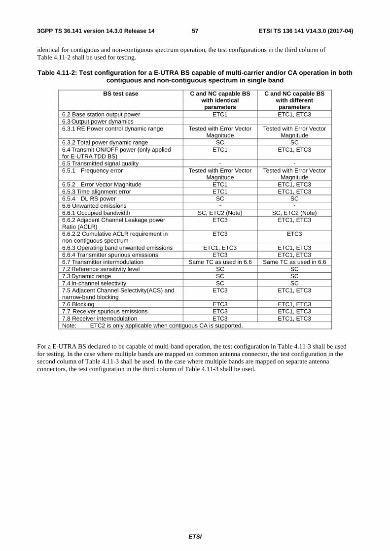
ETSI
ETSI TS 136 141 V14.3.0 (2017-04)573GPP TS 36.141 version 14.3.0 Release 14
identical for contiguous and non-contiguous spectrum operation, the test configurations in the third column of Table 4.11-2 shall be used for testing.
Table 4.11-2: Test configuration for a E-UTRA BS capable of multi-carrier and/or CA operation in both contiguous and non-contiguous spectrum in single band
BS test case C and NC capable BS with identical parameters
C and NC capable BS with different parameters
6.2 Base station output power ETC1 ETC1, ETC3 6.3 Output power dynamics 6.3.1 RE Power control dynamic range Tested with Error Vector
Magnitude Tested with Error Vector
Magnitude 6.3.2 Total power dynamic range SC SC 6.4 Transmit ON/OFF power (only applied for E-UTRA TDD BS)
ETC1 ETC1, ETC3
6.5 Transmitted signal quality - - 6.5.1 Frequency error Tested with Error Vector
Magnitude Tested with Error Vector
Magnitude 6.5.2 Error Vector Magnitude ETC1 ETC1, ETC3 6.5.3 Time alignment error ETC1 ETC1, ETC3 6.5.4 DL RS power SC SC 6.6 Unwanted emissions - - 6.6.1 Occupied bandwidth SC, ETC2 (Note) SC, ETC2 (Note) 6.6.2 Adjacent Channel Leakage power Ratio (ACLR)
ETC3 ETC1, ETC3
6.6.2.2 Cumulative ACLR requirement in non-contiguous spectrum
ETC3 ETC3
6.6.3 Operating band unwanted emissions ETC1, ETC3 ETC1, ETC3 6.6.4 Transmitter spurious emissions ETC3 ETC1, ETC3 6.7 Transmitter intermodulation Same TC as used in 6.6 Same TC as used in 6.6 7.2 Reference sensitivity level SC SC 7.3 Dynamic range SC SC 7.4 In-channel selectivity SC SC 7.5 Adjacent Channel Selectivity(ACS) and narrow-band blocking
ETC3 ETC1, ETC3
7.6 Blocking ETC3 ETC1, ETC3 7.7 Receiver spurious emissions ETC3 ETC1, ETC3 7.8 Receiver intermodulation ETC3 ETC1, ETC3 Note: ETC2 is only applicable when contiguous CA is supported.
For a E-UTRA BS declared to be capable of multi-band operation, the test configuration in Table 4.11-3 shall be used for testing. In the case where multiple bands are mapped on common antenna connector, the test configuration in the second column of Table 4.11-3 shall be used. In the case where multiple bands are mapped on separate antenna connectors, the test configuration in the third column of Table 4.11-3 shall be used.

ETSI
ETSI TS 136 141 V14.3.0 (2017-04)583GPP TS 36.141 version 14.3.0 Release 14
Table 4.11-3: Test configuration for a E-UTRA BS capable of multi-band operation
BS test case Test configuration
Common antenna connector
Separate antenna connector
6.2 Base station output power ETC1/3 (Note 1), ETC4 ETC1/3 (Note 1), ETC4
6.3 Output power dynamics
6.3.1 RE Power control dynamic range Tested with Error Vector Magnitude
Tested with Error Vector Magnitude
6.3.2 Total power dynamic range SC SC
6.4 Transmit ON/OFF power (only applied for E-UTRA TDD BS) ETC4 ETC4
6.5 Transmitted signal quality
6.5.1 Frequency error Tested with Error Vector Magnitude
Tested with Error Vector Magnitude
6.5.2 Error Vector Magnitude ETC1/3 (Note 1), ETC4 ETC1/3 (Note 1), ETC4
6.5.3 Time alignment error ETC1/3 (Note 1), ETC5 (Note 2)
ETC1/3 (Note 1), ETC5 (Note 2)
6.5.4 DL RS power SC SC
6.6 Unwanted emissions
6.6.1 Occupied bandwidth SC, ETC2 (Note 3) SC, ETC2 (Note 3) 6.6.2 Adjacent Channel Leakage power Ratio (ACLR) ETC1/3 (Note 1), ETC5
(Note 4) ETC1/3 (Note 1, 5),
ETC5 (Note 4, 5) 6.6.2.6 Cumulative ACLR requirement in non-contiguous spectrum
ETC3 (Note 1), ETC5 (Note 4)
ETC3 (Note 1, 5)
6.6.3 Operating band unwanted emissions ETC1/3 (Note 1), ETC5 ETC1/3 (Note 1, 5), ETC5 (Note 5)
6.6.4 Transmitter spurious emissions ETC1/3 (Note 1), ETC5 ETC1/3 (Note 1, 5), ETC5 (Note 5)
6.7 Transmitter intermodulation ETC1/3 (Note 1) ETC1/3 (Note 1, 5) 7.2 Reference sensitivity level SC SC 7.3 Dynamic range SC SC 7.4 In-channel selectivity SC SC 7.5 Adjacent Channel Selectivity(ACS) and narrow-band blocking ETC5 ETC1/3 (Note 1),
ETC5 (Note 6) 7.6 Blocking ETC5 ETC1/3 (Note 1),
ETC5 (Note 6) 7.7 Receiver spurious emissions ETC1/3 (Note 1), ETC5 ETC1/3 (Note 1, 5),
ETC5 (Note 5) 7.8 Receiver intermodulation ETC5 ETC1/3 (Note 1),
ETC5 (Note 6) Note 1: ETC1 and/or ETC3 shall be applied in each supported operating band according to Tables 4.11-1 and
4.11-2. Note 2: ETC5 is only applicable when inter-band CA is supported. Note 3: ETC2 is only applicable when contiguous CA is supported. Note 4: ETC5 may be applied for Inter RF Bandwidth gap only. Note 5: Single-band requirement apply to each antenna connector for both multi-band operation test and single-
band operation test. For single-band operation test, other antenna connector(s) is (are) terminated. Note 6: ETC5 is only applicable for multi-band receiver.
For a NB-IoT standalone BS declared to be capable of single carrier operation only, a single carrier (SCNS) shall be used for testing.
For a NB-IoT standalone BS declared to be capable of multi-carrier in contiguous spectrum operation in single band only, the test configurations in Table 4.11-4 shall be used for testing.

ETSI
ETSI TS 136 141 V14.3.0 (2017-04)593GPP TS 36.141 version 14.3.0 Release 14
Table 4.11-4: Test configurations for a NB-IoT standalone BS capable of multi-carrier in contiguous spectrum in single band only
BS test case Contiguous spectrum capable BS
6.2 Base station output power ETC6 6.3 Output power dynamics 6.3.1 RE Power control dynamic range Not applicable 6.3.2 Total power dynamic range Not applicable 6.3.3 NB-IoT RB power dynamic range for in-band or guard band operation
Not applicable
6.4 Transmit ON/OFF power (only applied for E-UTRA TDD BS)
Not Applicable
6.5 Transmitted signal quality - 6.5.1 Frequency error Tested with Error Vector
Magnitude 6.5.2 Error Vector Magnitude ETC6 6.5.3 Time alignment error ETC6 6.5.4 DL RS power SCNS 6.6 Unwanted emissions - 6.6.1 Occupied bandwidth SCNS 6.6.2 Adjacent Channel Leakage power Ratio (ACLR) ETC6 6.6.3 Operating band unwanted emissions ETC6 6.6.4 Transmitter spurious emissions ETC6 6.7 Transmitter intermodulation ETC6 7.2 Reference sensitivity level SCNS 7.3 Dynamic range SCNS 7.4 In-channel selectivity Not applicable 7.5 Adjacent Channel Selectivity(ACS) and narrow-band blocking
ETC6
7.6 Blocking ETC6 7.7 Receiver spurious emissions ETC6 7.8 Receiver intermodulation ETC6
For a BS supporting NB-IoT in-band and declared to be capable of single NB-IoT carrier operation only, a single carrier (SCNI) shall be used for testing. For a BS supporting NB-IoT in guard band and declared to be capable of single NB-IoT carrier operation only, a single carrier (SCNG) shall be used for testing.
For a E-UTRA with NB-IoT operating in-band and/or guard band BS declared to be capable of multi-carrier in contiguous spectrum operation in single band only, the test configurations in Table 4.11-5 shall be used for testing.
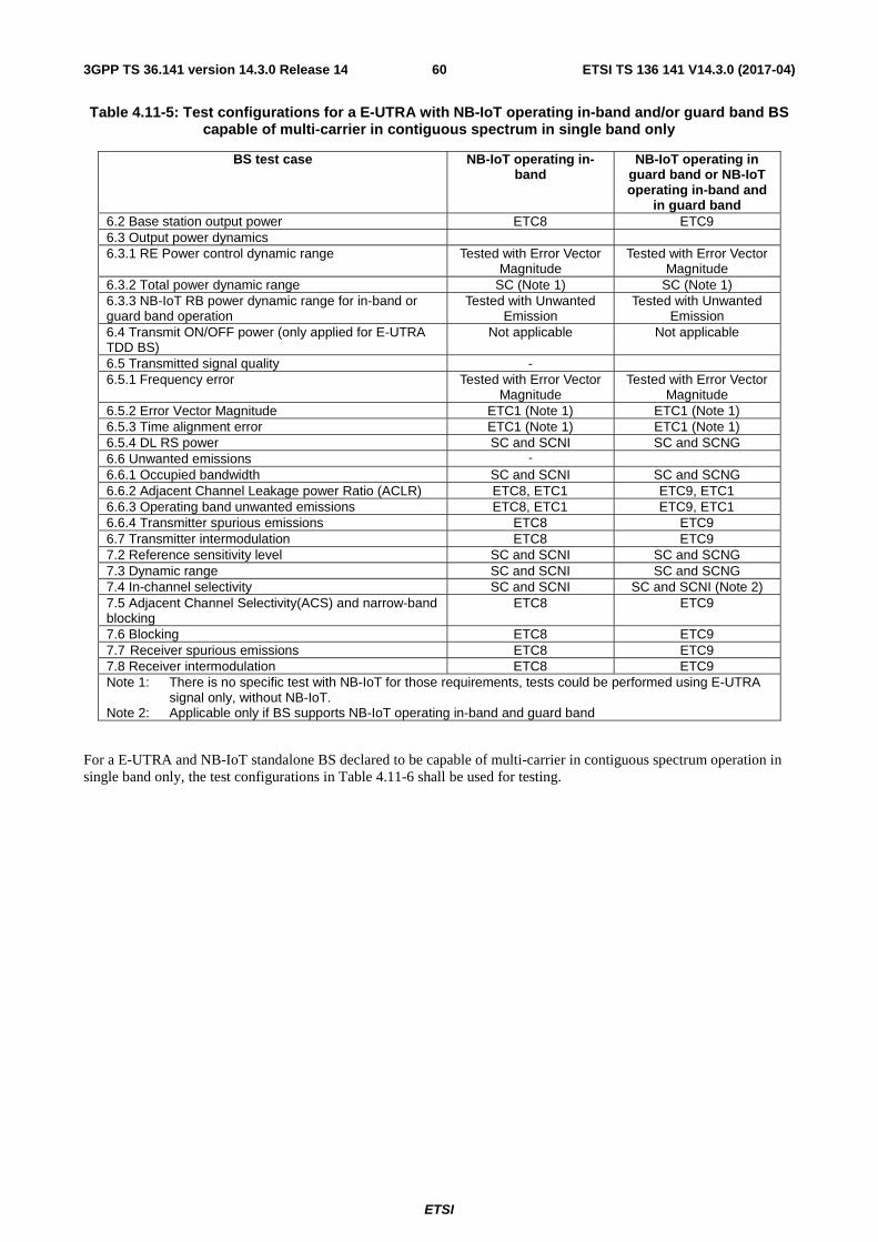
ETSI
ETSI TS 136 141 V14.3.0 (2017-04)603GPP TS 36.141 version 14.3.0 Release 14
Table 4.11-5: Test configurations for a E-UTRA with NB-IoT operating in-band and/or guard band BS capable of multi-carrier in contiguous spectrum in single band only
BS test case NB-IoT operating in-band
NB-IoT operating in guard band or NB-IoT operating in-band and
in guard band 6.2 Base station output power ETC8 ETC9 6.3 Output power dynamics 6.3.1 RE Power control dynamic range Tested with Error Vector
Magnitude Tested with Error Vector
Magnitude 6.3.2 Total power dynamic range SC (Note 1) SC (Note 1) 6.3.3 NB-IoT RB power dynamic range for in-band or guard band operation
Tested with Unwanted Emission
Tested with Unwanted Emission
6.4 Transmit ON/OFF power (only applied for E-UTRA TDD BS)
Not applicable Not applicable
6.5 Transmitted signal quality - 6.5.1 Frequency error Tested with Error Vector
Magnitude Tested with Error Vector
Magnitude 6.5.2 Error Vector Magnitude ETC1 (Note 1) ETC1 (Note 1) 6.5.3 Time alignment error ETC1 (Note 1) ETC1 (Note 1) 6.5.4 DL RS power SC and SCNI SC and SCNG 6.6 Unwanted emissions -
6.6.1 Occupied bandwidth SC and SCNI SC and SCNG 6.6.2 Adjacent Channel Leakage power Ratio (ACLR) ETC8, ETC1 ETC9, ETC1 6.6.3 Operating band unwanted emissions ETC8, ETC1 ETC9, ETC1 6.6.4 Transmitter spurious emissions ETC8 ETC9 6.7 Transmitter intermodulation ETC8 ETC9 7.2 Reference sensitivity level SC and SCNI SC and SCNG 7.3 Dynamic range SC and SCNI SC and SCNG 7.4 In-channel selectivity SC and SCNI SC and SCNI (Note 2) 7.5 Adjacent Channel Selectivity(ACS) and narrow-band blocking
ETC8 ETC9
7.6 Blocking ETC8 ETC9 7.7 Receiver spurious emissions ETC8 ETC9 7.8 Receiver intermodulation ETC8 ETC9 Note 1: There is no specific test with NB-IoT for those requirements, tests could be performed using E-UTRA
signal only, without NB-IoT. Note 2: Applicable only if BS supports NB-IoT operating in-band and guard band
For a E-UTRA and NB-IoT standalone BS declared to be capable of multi-carrier in contiguous spectrum operation in single band only, the test configurations in Table 4.11-6 shall be used for testing.

ETSI
ETSI TS 136 141 V14.3.0 (2017-04)613GPP TS 36.141 version 14.3.0 Release 14
Table 4.11-6: Test configurations for a E-UTRA and NB-IoT standalone BS capable of multi-carrier in contiguous spectrum in single band only
BS test case Contiguous spectrum capable BS
6.2 Base station output power ETC7 6.3 Output power dynamics 6.3. RE Power control dynamic range Tested with Error Vector
Magnitude 6.3.2 Total power dynamic range SC 6.3.3 NB-IoT RB power dynamic range for in-band or guard band operation
Not applicable
6.4 Transmit ON/OFF power (only applied for E-UTRA TDD BS)
ETC7
6.3.3 NB-IoT RB power dynamic range for in-band or guard band operation
Not applicable
6.5 Transmitted signal quality - 6.5.1 Frequency error Tested with Error Vector
Magnitude 6.5.2 Error Vector Magnitude ETC7 6.5.3 Time alignment error ETC7 6.5.4 DL RS power SC and SCNS 6.6 Unwanted emissions - 6.6.1 Occupied bandwidth SC and SCNS 6.6.2 Adjacent Channel Leakage power Ratio (ACLR) SC and SCNS 6.6.3 Operating band unwanted emissions ETC7 6.6.4 Transmitter spurious emissions ETC7 6.7 Transmitter intermodulation ETC7 7.2 Reference sensitivity level SC and SCNS 7.3 Dynamic range SC and SCNS 7.4 In-channel selectivity SC 7.5 Adjacent Channel Selectivity(ACS) and narrow-band blocking
ETC7
7.6 Blocking ETC7 7.7 Receiver spurious emissions ETC7 7.8 Receiver intermodulation ETC7
4.12 Requirements for BS capable of multi-band operation For BS capable of multi-band operation, the RF requirements in clause 6 and 7 apply for each supported operating band unless otherwise stated. For some requirements it is explicitly stated that specific additions or exclusions to the requirement apply for BS capable of multi-band operation.
For BS capable of multi-band operation, various structures in terms of combinations of different transmitter and receiver implementations (multi-band or single band) with mapping of transceivers to one or more antenna port(s) in different ways are possible. In the case where multiple bands are mapped on an antenna connector, the exclusions or provisions for multi-band capable BS are applicable to this antenna connector. In the case where a single band is mapped on an antenna connector, the following applies:
- Single-band ACLR, operating band unwanted emissions, transmitter spurious emissions, transmitter intermodulation and receiver spurious emissions requirements apply to this antenna connector that is mapped to single-band.
- If the BS is configured for single-band operation, single-band requirements shall apply to this antenna connector configured for single-band operation and no exclusions or provisions for multi-band capable BS are applicable. Single-band requirements are tested separately at the antenna connector configured for single-band operation, with all other antenna connectors terminated.
For a band supported by a Base Station where the transmitted carriers are not processed in active RF components together with carriers in any other band, single-band transmitter requirements shall apply. For a band supported by a Base Station where the received carriers are not processed in active RF components together with carriers in any other band, single-band receiver requirements shall apply.

ETSI
ETSI TS 136 141 V14.3.0 (2017-04)623GPP TS 36.141 version 14.3.0 Release 14
For a BS capable of multi-band operation supporting bands for TDD, the RF requirements in the present specification assume synchronized operation, where no simultaneous uplink and downlink occur between the supported operating bands.
The RF requirements in the present specification are FFS for multi-band operation supporting bands for both FDD and TDD.
4.13 Tests for BS capable of multi-band operation with three or more bands
For BS supports multiple multi-band combinations, the test(s) shall be applied using the following principles:
1) The supported multi-band combination covering the widest radio bandwidth should be tested.
2) Among the remaining supported multi-band combinations, the following ones should also be tested:
- Those with a larger rated total output power (per band or per band combination).
- Those with a larger total number of supported carriers (per band or per band combination).
- Those with a larger Maximum Base Station RF Bandwidth (per band).
5 Operating bands and channel arrangement
5.1 General The channel arrangements presented in this clause are based on the operating bands and channel bandwidths defined in the present release of specifications.
NOTE: Other operating bands and channel bandwidths may be considered in future releases.
5.2 Void
5.3 Void
5.4 Void
5.5 Operating bands E-UTRA is designed to operate in the operating bands defined in Table 5.5-1. Unless stated otherwise, requirements specified for the TDD duplex mode apply for downlink and uplink operations in Frame Structure Type 2.
NB-IoT is designed to operate in the E-UTRA operating bands 1, 2, 3, 5, 8, 11, 12, 13, 17, 18, 19, 20, 25, 26, 28, 31, 66, 70, which are defined in Table 5.5-1.

ETSI
ETSI TS 136 141 V14.3.0 (2017-04)633GPP TS 36.141 version 14.3.0 Release 14
Table 5.5-1: E-UTRA operating bands

ETSI
ETSI TS 136 141 V14.3.0 (2017-04)643GPP TS 36.141 version 14.3.0 Release 14
E-UTRA Operating
Band
Uplink (UL) operating band BS receive
UE transmit
Downlink (DL) operating band BS transmit UE receive
Duplex Mode
FUL_low – FUL_high FDL_low – FDL_high
1 1920 MHz – 1980 MHz 2110 MHz – 2170 MHz FDD 2 1850 MHz – 1910 MHz 1930 MHz – 1990 MHz FDD 3 1710 MHz – 1785 MHz 1805 MHz – 1880 MHz FDD 4 1710 MHz – 1755 MHz 2110 MHz – 2155 MHz FDD 5 824 MHz – 849 MHz 869 MHz – 894MHz FDD 6
(NOTE 1) 830 MHz – 840 MHz 875 MHz – 885 MHz FDD
7 2500 MHz – 2570 MHz 2620 MHz – 2690 MHz FDD 8 880 MHz – 915 MHz 925 MHz – 960 MHz FDD 9 1749.9 MHz – 1784.9 MHz 1844.9 MHz – 1879.9 MHz FDD 10 1710 MHz – 1770 MHz 2110 MHz – 2170 MHz FDD 11 1427.9 MHz – 1447.9 MHz 1475.9 MHz – 1495.9 MHz FDD 12 699 MHz – 716 MHz 729 MHz – 746 MHz FDD 13 777 MHz – 787 MHz 746 MHz – 756 MHz FDD 14 788 MHz – 798 MHz 758 MHz – 768 MHz FDD 15 Reserved Reserved FDD 16 Reserved Reserved FDD 17 704 MHz 716 MHz 734 MHz 746 MHz FDD 18 815 MHz – 830 MHz 860 MHz – 875 MHz FDD 19 830 MHz – 845 MHz 875 MHz – 890 MHz FDD 20 832 MHz – 862 MHz 791 MHz – 821 MHz FDD 21 1447.9 MHz – 1462.9 MHz 1495.9 MHz – 1510.9 MHz FDD 22 3410 MHz – 3490 MHz 3510 MHz – 3590 MHz FDD 231 2000 MHz – 2020 MHz 2180 MHz – 2200 MHz FDD 24 1626.5 MHz – 1660.5 MHz 1525 MHz – 1559 MHz FDD 25 1850 MHz – 1915 MHz 1930 MHz – 1995 MHz FDD 26 814 MHz – 849 MHz 859 MHz – 894 MHz FDD 27 807 MHz – 824 MHz 852 MHz – 869 MHz FDD 28 703 MHz – 748 MHz 758 MHz – 803 MHz FDD 29 N/A 717 MHz – 728 MHz FDD
30 2305 MHz – 2315 MHz 2350 MHz – 2360 MHz FDD (NOTE 2)
31 452.5 MHz – 457.5 MHz 462.5 MHz – 467.5 MHz FDD 32 N/A 1452 MHz – 1496 MHz FDD
(NOTE 2) 33 1900 MHz – 1920 MHz 1900 MHz – 1920 MHz TDD 34 2010 MHz – 2025 MHz 2010 MHz – 2025 MHz TDD 35 1850 MHz – 1910 MHz 1850 MHz – 1910 MHz TDD 36 1930 MHz – 1990 MHz 1930 MHz – 1990 MHz TDD 37 1910 MHz – 1930 MHz 1910 MHz – 1930 MHz TDD 38 2570 MHz – 2620 MHz 2570 MHz – 2620 MHz TDD 39 1880 MHz – 1920 MHz 1880 MHz – 1920 MHz TDD 40 2300 MHz – 2400 MHz 2300 MHz – 2400 MHz TDD 41 2496 MHz – 2690 MHz 2496 MHz – 2690 MHz TDD 42 3400 MHz – 3600 MHz 3400 MHz – 3600 MHz TDD 43 3600 MHz – 3800 MHz 3600 MHz – 3800 MHz TDD 44 703 MHz – 803 MHz 703 MHz – 803 MHz TDD 45 1447 MHz – 1467 MHz 1447 MHz – 1467 MHz TDD 46 5150 MHz – 5925 MHz 5150 MHz – 5925 MHz TDD
(NOTE 3, NOTE 4)
47 5855 MHz – 5925 MHz 5855 MHz – 5925 MHz TDD (NOTE 7)
48 3550 MHz – 3700 MHz 3550 MHz – 3700 MHz TDD 65 1920 MHz – 2010 MHz 2110 MHz – 2200 MHz FDD 66 1710 MHz – 1780 MHz 2110 MHz – 2200 MHz FDD
(NOTE 5) 67 N/A 738 MHz – 758 MHz FDD
(NOTE 2) 68 698 MHz – 728 MHz 753 MHz – 783 MHz FDD

ETSI
ETSI TS 136 141 V14.3.0 (2017-04)653GPP TS 36.141 version 14.3.0 Release 14
69 N/A 2570 MHz – 2620 MHz FDD (NOTE 2)
70 1695 MHz – 1710 MHz 1995 MHz – 2020 MHz FDD (NOTE 6)
NOTE 1: Band 6, 23 are not applicable. NOTE 2: Restricted to E-UTRA operation when carrier aggregation is configured. The downlink
operating band is paired with the uplink operating band (external) of the carrier aggregation configuration that is supporting the configured Pcell.
NOTE 3: This band is an unlicensed band restricted to licensed-assisted operation using Frame Structure Type 3.
NOTE 4: In this version of the specification, restricted to E-UTRA DL operation when carrier aggregation is configured. Band 46 is divided into four sub-bands as in Table 5.5-1A.
NOTE 5: The range 2180 – 2200 MHz of the DL operating band is restricted to E-UTRA operation when carrier aggregation is configured.
NOTE 6: The range 2010-2020 MHz of the DL operating band is restricted to E-UTRA operation when carrier aggregation is configured and TX-RX separation is 300 MHz. The range 2005-2020 MHz of the DL operating band is restricted to E-UTRA operation when carrier aggregation is configured and TX-RX separation is 295 MHz.
NOTE 7: No BS requirement is defined for this band.
Table 5.5-1A Sub-bands for Band 46
E-UTRA Operating Band
Uplink (UL) operating band BS receive UE transmit
Downlink (DL) operating band
BS transmit UE receive
FUL_low – FUL_high FDL_low – FDL_high
46a 5150 MHz – 5250 MHz 5150 MHz – 5250 MHz 46b 5250 MHz – 5350 MHz 5250 MHz – 5350 MHz 46c 5470 MHz – 5725 MHz 5470 MHz – 5725 MHz 46d 5725 MHz – 5925 MHz 5725 MHz – 5925 MHz
E-UTRA is designed to operate for the carrier aggregation bands defined in Tables 5.5-2 to 5.5-4.
Table 5.5-2: Intra-band contiguous carrier aggregation bands
CA Band E-UTRA operating band
CA_1 1 CA_2 2 CA_3 3 CA_5 5 CA_7 7 CA_8 8 CA_12 12 CA_23 23 CA_27 27 CA_38 38 CA_39 39 CA_40 40 CA_41 41 CA_42 42 CA_48 48 CA_66 66 CA_70 70

ETSI
ETSI TS 136 141 V14.3.0 (2017-04)663GPP TS 36.141 version 14.3.0 Release 14
Table 5.5-3: Inter-band carrier aggregation bands (two bands)

ETSI
ETSI TS 136 141 V14.3.0 (2017-04)673GPP TS 36.141 version 14.3.0 Release 14
CA Band E-UTRA operating bands
CA_1-3 1 3
CA_1-3-3 1 3
CA_1-5 1 5
CA_1-7 1 7
CA_1-7-7 1 7
CA_1-8 1 8
CA_1-11 1 11
CA_1-18 1 18
CA_1-19 1 19
CA_1-20 1 20
CA_1-21 1 21
CA_1-26 1 26
CA_1-28 1 28
CA_1-38 1 38
CA_1-40 1 40
CA_1-41 1 41
CA_1-42 1 42
CA_1-46 1 46
CA_2-4 2 4
CA_2-2-4 2 4
CA_2-2-4-4 2 4
CA_2-4-4 2 4
CA_2-5 2 5
CA_2-2-5 2 5
CA_2-7 2 7
CA_2-7-7 2 7
CA_2-12 2 12
CA_2-2-12 2 12
CA_2-2-12-12 2 12
CA_2-12-12 2 12
CA_2-13 2 13
CA_2-2-13 2

ETSI
ETSI TS 136 141 V14.3.0 (2017-04)683GPP TS 36.141 version 14.3.0 Release 14
13
CA_2-17 2 17
CA_2-28 2 28
CA_2-29 2 29
CA_2-30 2 30
CA_2-2-30 2 30
CA_2-46 2 46
CA_2-46-46 2 46
CA_2-66 2 66
CA_2-2-66 2 66
CA_2-2-66-66 2 66
CA_2-66-66 2 66
CA_3-5 3 5
CA_3-7 3 7
CA_3-3-7 3 7
CA_3-3-7-7 3 7
CA_3-7-7 3 7
CA_3-8 3 8
CA_3-3-8 3 8
CA_3-11 3 11

ETSI
ETSI TS 136 141 V14.3.0 (2017-04)693GPP TS 36.141 version 14.3.0 Release 14
CA_3-19 3 19
CA_3-20 3 20
CA_3-3-20 3 20
CA_3-21 3 21
CA_3-26 3 26
CA_3-27 3 27
CA_3-28 3 28
CA_3-31 3 31
CA_3-32 3 32
CA_3-38 3 38
CA_3-40 3 40
CA_3-40-40 3 40
CA_3-41 3 41
CA_3-42 3 42
CA_3-46 3 46
CA_3-69 3 69
CA_4-5 4 5
CA_4-4-5 4 5
CA_4-7 4 7
CA_4-4-7 4 7
CA_4-7-7 4 7
CA_4-12 4 12
CA_4-4-12 4 12
CA_4-4-12-12 4 12
CA_4-12-12 4 12
CA_4-13 4 13
CA_4-4-13 4 13
CA_4-17 4 17
CA_4-27 4 27
CA_4-28 4 28
CA_4-29 4 29
CA_4-4-29 4 29
CA_4-30 4
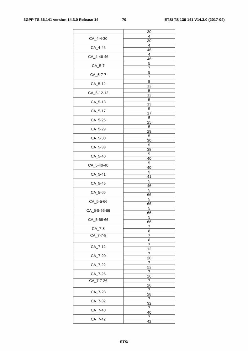
ETSI
ETSI TS 136 141 V14.3.0 (2017-04)703GPP TS 36.141 version 14.3.0 Release 14
30
CA_4-4-30 4 30
CA_4-46 4 46
CA_4-46-46 4 46
CA_5-7 5 7
CA_5-7-7 5 7
CA_5-12 5 12
CA_5-12-12 5 12
CA_5-13 5 13
CA_5-17 5 17
CA_5-25 5 25
CA_5-29 5 29
CA_5-30 5 30
CA_5-38 5 38
CA_5-40 5 40
CA_5-40-40 5 40
CA_5-41 5 41
CA_5-46 5 46
CA_5-66 5 66
CA_5-5-66 5 66
CA_5-5-66-66 5 66
CA_5-66-66 5 66
CA_7-8 7 8
CA_7-7-8 7 8
CA_7-12 7 12
CA_7-20 7 20
CA_7-22 7 22
CA_7-26 7 26
CA_7-7-26 7 26
CA_7-28 7 28
CA_7-32 7 32
CA_7-40 7 40
CA_7-42 7 42

ETSI
ETSI TS 136 141 V14.3.0 (2017-04)713GPP TS 36.141 version 14.3.0 Release 14
CA_7-42-42 7 42
CA_7-46 7 46
CA_7-66 7 66
CA_8-11 8 11
CA_8-20 8 20
CA_8-28 8 28
CA_8-39 8 39
CA_8-40 8 40
CA_8-41 8 41
CA_8-42 8 42
CA_8-46 8 46
CA_11-18 11 18
CA_11-28 11 28
CA_11-41 11 41
CA_11-42 11 42
CA_11-46 11 46

ETSI
ETSI TS 136 141 V14.3.0 (2017-04)723GPP TS 36.141 version 14.3.0 Release 14
CA_12-25 12 25
CA_12-30 12 30
CA_12-66 12 66
CA_12-66-66 12 66
CA_13-46 13 46
CA_13-66 13 66
CA_13-66-66 13 66
CA_18-28 18 28
CA_19-21 19 21
CA_19-28 19 28
CA_19-42 19 42
CA_19-46 19 46
CA_20-28 20 28
CA_20-31 20 31
CA_20-32 20 32
CA_20-38 20 38
CA_20-40 20 40
CA_20-42 20 42
CA_20-42-42 20 42
CA_20-67 20 67
CA_21-28 21 28
CA_21-42 21 42
CA_21-46 21 46
CA_23-29 23 29
CA_25-26 25 26
CA_25-41 25 41
CA_26-46 26 46
CA_26-41 26 41
CA_28-40 28 40
CA_28-41 28 41
CA_28-42 28 42
CA_28-46 28 46

ETSI
ETSI TS 136 141 V14.3.0 (2017-04)733GPP TS 36.141 version 14.3.0 Release 14
CA_29-30 29 30
CA_29-66 29 66
CA_29-66-66 29 66
CA_29-70 29 70
CA_30-66 30 66
CA_30-66-66 30 66
CA_38-40 38 40
CA_38-40-40 38 40
CA_39-41 39 41
CA_39-46 39 46
CA_40-41 40 41
CA_40-42 40 42
CA_40-46 40 46
CA_41-42 41 42
CA_41-46 41 46
CA_42-46 42 46
CA_46-66 46 66
CA_46-46-66 46 66
CA_46-66-66 46 66
CA_46-70 46 70
Table 5.5-3A: Inter-band carrier aggregation bands (three bands)
CA Band E-UTRA operating bands
CA_1-3-5 1 3 5
CA_1-3-7 1 3 7
CA_1-3-7-7 1 3 7
CA_1-3-8 1 3 8
CA_1-3-3-8 1 3 8

ETSI
ETSI TS 136 141 V14.3.0 (2017-04)743GPP TS 36.141 version 14.3.0 Release 14
CA_1-3-11 1 3 11
CA_1-3-19 1 3 19
CA_1-3-20 1 3 20
CA_1-3-21 1 3 21
CA_1-3-26 1 3 26
CA_1-3-28 1 3 28
CA_1-3-38 1 3 38
CA_1-3-40 1 3 40
CA_1-5-46 1 5 46
CA_1-3-41 1 3 41
CA_1-3-42 1 3 42
CA_1-5-7 1 5 7
CA_1-5-7-7 1 5 7
CA_1-5-40 1 5 40
CA_1-7-8 1 7 8
CA_1-7-20 1 7 20
CA_1-7-26 1 7 26
CA_1-7-7-26 1 7 26

ETSI
ETSI TS 136 141 V14.3.0 (2017-04)753GPP TS 36.141 version 14.3.0 Release 14
CA_1-7-28 1 7 28
CA_1-7-40 1 7 40
CA_1-7-42 1 7 42
CA_1-7-46 1 7 46
CA_1-8-11 1 8 11
CA_1-8-28 1 8 28
CA_1-8-40 1 8 40
CA_1-11-18 1 11 18
CA_1-11-28 1 11 28
CA_1-18-28 1 18 28
CA_1-19-21 1 19 21
CA_1-19-28 1 19 28
CA_1-19-42 1 19 42
CA_1-20-42 1 20 42
CA_1-21-28 1 21 28
CA_1-21-42 1 21 42
CA_1-28-42 1 28 42
CA_1-41-42 1 41 42
CA_2-4-5 2 4 5
CA_2-4-12 2 4 12
CA_2-2-4-5 2 4 5
CA_2-4-4-5 2 4

ETSI
ETSI TS 136 141 V14.3.0 (2017-04)763GPP TS 36.141 version 14.3.0 Release 14
5
CA_2-4-7 2 4 7
CA_2-4-7-7 2 4 7
CA_2-2-4-12 2 4 12
CA_2-4-4-12 2 4 12
CA_2-4-12-12 2 4 12
CA_2-4-13 2 4 13
CA_2-4-29 2 4 29
CA_2-4-30 2 4 30
CA_2-5-12 2 5 12
CA_2-2-5-12 2 5 12
CA_2-5-12-12 2 5 12
CA_2-2-5-30 2 5 30
CA_2-2-12-30 2 12 30
CA_2-2-12-66 2 12 66
CA_2-2-30-66 2 30 66
CA_2-5-13 2 5 13
CA_2-5-29 2 5 29
CA_2-5-30 2 5 30
CA_2-2-5-66 2 5 66
CA_2-2-5-66-66 2 5 66

ETSI
ETSI TS 136 141 V14.3.0 (2017-04)773GPP TS 36.141 version 14.3.0 Release 14
CA_2-5-66 2 5 66
CA_2-5-66-66 2 5 66
CA_2-7-12 2 7 12
CA_2-7-66 2 7 66
CA_2-12-30 2 12 30
CA_2-12-66 2 12 66
CA_2-12-66-66 2 12 66
CA_2-2-13-66 2 13 66
CA_2-13-66 2 13 66
CA_2-13-66-66 2 13 66
CA_2-29-30 2 29 30
CA_2-30-66 2 30 66
CA_2-30-66-66 2 30 66
CA_2-46-66 2 46 66
CA_2-46-46-66 2 46 66

ETSI
ETSI TS 136 141 V14.3.0 (2017-04)783GPP TS 36.141 version 14.3.0 Release 14
CA_3-5-7 3 5 7
CA_3-5-7-7 3 5 7
CA_3-5-40 3 5 40
CA_3-3-7-8 3 7 8
CA_3-7-7-8 3 7 8
CA_3-7-8 3 7 8
CA_3-3-7-7-8 3 7 8
CA_3-7-20 3 7 20
CA_3-7-26 3 7 26
CA_3-7-7-26 3 7 26

ETSI
ETSI TS 136 141 V14.3.0 (2017-04)793GPP TS 36.141 version 14.3.0 Release 14
CA_3-7-28 3 7 28
CA_3-7-32 3 7 32
CA_3-7-38 3 7 38
CA_3-7-40 3 7 40
CA_3-7-42 3 7 42
CA_3-8-11 3 8 11
CA_3-8-28 3 8 28
CA_3-8-40 3 8 40
CA_3-11-28 3 11 28
CA_3-19-21 3 19 21
CA_3-19-42 3 19 42
CA_3-20-32 3 20 32
CA_3-20-42 3 20 42
CA_3-21-28 3 21 28
CA_3-21-42 3 21 42
CA_3-28-40 3 28 40
CA_3-28-41 3

ETSI
ETSI TS 136 141 V14.3.0 (2017-04)803GPP TS 36.141 version 14.3.0 Release 14
28 41
CA_3-28-42 3 28 42
CA_3-41-42 3 41 42
CA_4-5-12 4 5 12
CA_4-4-5-12 4 5 12
CA_4-5-12-12 4 5 12
CA_4-5-13 4 5 13
CA_4-5-29 4 5 29
CA_4-5-30 4 5 30
CA_4-4-5-30 4 5 30
CA_4-7-12 4 7 12
CA_4-12-30 4 12 30
CA_4-4-12-30 4 12 30
CA_4-29-30 4 29 30
CA_4-4-29-30 4 29 30
CA_5-7-46 5 7 46
CA_5-12-66 5 12 66
CA_5-30-66 5 30 66
CA_5-30-66-66 5 30 66
CA_5-40-41 5 40 41
CA_7-8-20 7 8 20
CA_7-20-38 7 20 38

ETSI
ETSI TS 136 141 V14.3.0 (2017-04)813GPP TS 36.141 version 14.3.0 Release 14
CA_7-20-42 7 20 42
CA_8-11-28 8 11 28
CA_8-28-41 8 28 41
CA_12-30-66 12 30 66
CA_19-21-42 19 21 42
CA_21-28-42 21 28 42
CA_28-41-42 28 41 42
CA_29-46-66 29 46 66
Table 5.5-3B: Inter-band carrier aggregation bands (four bands)
CA Band E-UTRA operating bands
CA_1-3-5-7
1 3 5 7
CA_1-3-5-7-7
1 3 5 7
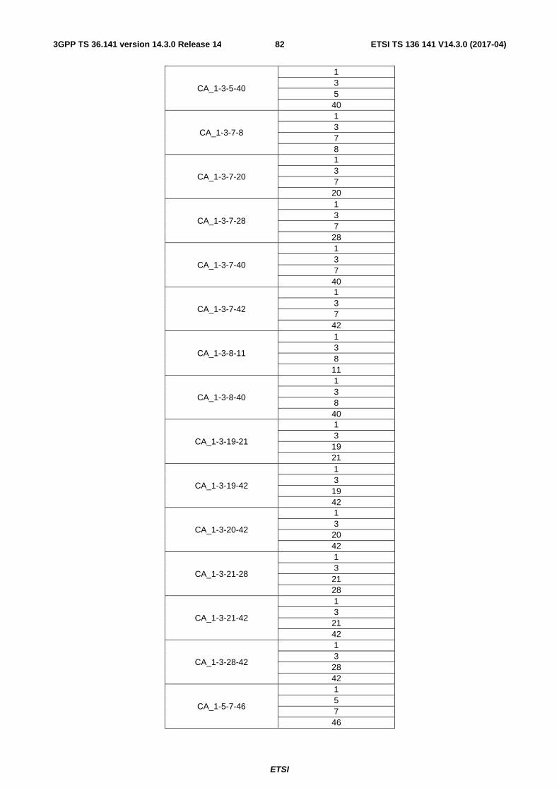
ETSI
ETSI TS 136 141 V14.3.0 (2017-04)823GPP TS 36.141 version 14.3.0 Release 14
CA_1-3-5-40
1 3 5 40
CA_1-3-7-8
1 3 7 8
CA_1-3-7-20
1 3 7 20
CA_1-3-7-28
1 3 7 28
CA_1-3-7-40
1 3 7 40
CA_1-3-7-42
1 3 7 42
CA_1-3-8-11
1 3 8 11
CA_1-3-8-40
1 3 8 40
CA_1-3-19-21
1 3 19 21
CA_1-3-19-42
1 3 19 42
CA_1-3-20-42
1 3 20 42
CA_1-3-21-28
1 3 21 28
CA_1-3-21-42
1 3 21 42
CA_1-3-28-42
1 3 28 42
CA_1-5-7-46
1 5 7 46

ETSI
ETSI TS 136 141 V14.3.0 (2017-04)833GPP TS 36.141 version 14.3.0 Release 14
CA_1-7-20-42
1 7 20 42
CA_1-19-21-42
1 19 21 42
CA_1-21-28-42
1 21 28 42
CA_2-4-5-12
2 4 5 12
CA_2-4-5-29
2 4 5 29
CA_2-4-5-30
2 4 5 30
CA_2-4-7-12
2 4 7 12
CA_2-4-12-30
2 4 12 30
CA_2-4-29-30
2 4 29 30
CA_2-2-5-12-66
2 5 12 66
CA_2-2-5-30-66
2 5 30 66
CA_2-5-30-66-66
2 5 30 66
CA_2-2-12-30-66
2 12 30 66
CA_2-5-30-66
2 5 30 66
CA_2-5-12-66
2 5 12 66

ETSI
ETSI TS 136 141 V14.3.0 (2017-04)843GPP TS 36.141 version 14.3.0 Release 14
CA_2-12-30-66
2 12 30 66
CA_3-7-20-42
3 7 20 42
CA_3-19-21-42
3 19 21 42
CA_3-28-41-42
3 28 41 42
Table 5.5-3C. Inter-band carrier aggregation bands (five bands)
CA Band E-UTRA operating bands
CA_1-3-7-20-42 1 3 7 20 42
Table 5.5-4: Intra-band non-contiguous carrier aggregation bands (with two sub-blocks)
CA Band E-UTRA operating band
CA_2-2 2 CA_3-3 3 CA_4-4 4 CA_5-5 5 CA_7-7 7
CA_12-12 12 CA_23-23 23 CA_25-25 25 CA_40-40 40 CA_41-41 41 CA_42-42 42 CA_48-48 48 CA_66-66 66
5.6 Channel bandwidth For E-UTRA, requirements in present document are specified for the channel bandwidths listed in Table 5.6-1.
Table 5.6-1: Transmission bandwidth configuration NRB in E-UTRA channel bandwidths
Channel bandwidth BWChannel [MHz] 1.4 3 5 10 15 20
Transmission bandwidth configuration NRB 6 15 25 50 75 100

ETSI
ETSI TS 136 141 V14.3.0 (2017-04)853GPP TS 36.141 version 14.3.0 Release 14
For E-UTRA, figure 5.6-1 shows the relation between the Channel bandwidth (BWChannel) and the Transmission bandwidth configuration (NRB). The channel edges are defined as the lowest and highest frequencies of the carrier separated by the channel bandwidth, i.e. at FC +/- BWChannel /2.
Transmission Bandwidth [RB]
Transmission Bandwidth Configuration [RB]
Channel Bandwidth [MHz]
Center subcarrier (corresponds to DC in baseband) is not transmitted in downlink
Active Resource Blocks
Ch
ann
el edg
e
Ch
ann
el edg
e
Reso
urce b
lock
Figure 5.6-1: Definition of Channel Bandwidth and Transmission Bandwidth Configuration for one E-UTRA carrier.
Figure 5.6-2 illustrates the Aggregated Channel Bandwidth for intra-band carrier aggregation.
FC_low
Lo
wer E
dg
e
Hig
her E
dg
e
Lowest Carrier Transmission Bandwidth
Configuration [RB]
FC_high
Foffset
Highest Carrier Transmission Bandwidth
Configuration [RB]
Reso
urce b
lock
Aggregated Channel Bandwidth, BWchannel_CA [MHz]
Fedge_low Fedge_high For each carrier, the center sub carrier (corresponds to DC in baseband) is not transmitted in downlink
Foffset
Figure 5.6-2: Definition of Aggregated Channel Bandwidth for intra-band carrier aggregation
The lower edge of the Aggregated Channel Bandwidth (BWChannel_CA) is defined as Fedge_low = FC_low - Foffset. The upper edge of the Aggregated Channel Bandwidth is defined as Fedge_high = FC_high + Foffset. The Aggregated Channel Bandwidth, BWChannel_CA, is defined as follows:
BWChannel_CA = Fedge_high - Fedge_low [MHz]
Figure 5.6-3: illustrates the sub-block bandwidth for a BS operating in non-contiguous spectrum.

ETSI
ETSI TS 136 141 V14.3.0 (2017-04)863GPP TS 36.141 version 14.3.0 Release 14
Figure 5.6-3: Definition of Sub-block Bandwidth for intra-band non-contiguous spectrum
The lower sub-block edge of the sub-block bandwidth (BWChannel,block) is defined as Fedge,block, low = FC,block,low - Foffset. The upper sub-block edge of the sub-block bandwidth is defined as Fedge,block,high = FC,block,high + Foffset. The sub-block bandwidth, BWChannel,block, is defined as follows:
BWChannel,block = Fedge,block,high - Fedge,block,low [MHz]
Foffset is defined in Table 5.6-2 below where BWChannel is defined in Table 5.6-1.
Table 5.6-2: Definition of Foffset
Channel Bandwidth of the Lowest or Highest Carrier: BWChannel[MHz]
Foffset[MHz]
5, 10, 15, 20 BWChannel/2
NOTE 1: Foffset is calculated separately for each Base Station RF Bandwidth edge / sub-block edge.
NOTE 2: The values of BWChannel_CA /sub-block bandwidth for UE and BS are the same if the channel bandwidths of lowest and the highest component carriers are identical.
For NB-IoT, requirements in present document are specified for the channel bandwidths listed in Table 5.6-3.
Table 5.6-3: Transmission bandwidth configuration NRB, Ntone 15kHz and Ntone 3.75kHz in NB-IoT channel bandwidth
NB-IoT Standalone In-band Guard Band
Channel bandwidth BWChannel [kHz] 200
E-UTRA channel bandwidth in Table 5.6-1
E-UTRA channel bandwidth in Table 5.6-1 for CBW>3MHz
Transmission bandwidth configuration NRB 1 1 1
Transmission bandwidth configuration Ntone 15kHz
12 12 12
Transmission bandwidth configuration Ntone 3.75kHz
48 48 48
For NB-IoT standalone operation, figure 5.6-4 shows the relation between the channel bandwidth (BWChannel) and the transmission bandwidth configuration (NRB, Ntone 15kHz and Ntone 3.75kHz) for NB-IoT standalone operation. The channel
FC,block 1,low
...
Lo
wer S
ub
-blo
ck Ed
ge
Up
per S
ub
-blo
ck Ed
ge
Transmission Bandwidth
Configuration of the lowest carrier in a sub-
block [RB]
FC,block 1,high Foffset
Transmission Bandwidth
Configuration of the highest carrier in a
sub-block [RB]
Res
ou
rce b
lock
Sub-block Bandwidth, BWChannel,block [MHz]
Fedge,block 1, low Fedge,block 1,high For each carrier, the center sub carrier (corresponds to DC in
baseband) is not transmitted in downlink
Foffset
Sub block n Sub block 1
Base Station RF Bandwidth
FC,block n,low
Lo
wer S
ub
-blo
ck Ed
ge
Up
per S
ub
-blo
ck Ed
ge
Transmission Bandwidth
Configuration of the lowest carrier in a sub-block [RB]
FC,block n,high Foffset
Transmission Bandwidth
Configuration of the highest carrier in a
sub-block [RB]
Reso
urce b
lock
Sub-block Bandwidth, BWChannel,block [MHz]
Fedge,block n, low Fedge,block n,high For each carrier, the center sub carrier (corresponds to DC in
baseband) is not transmitted in downlink
Foffset

ETSI
ETSI TS 136 141 V14.3.0 (2017-04)873GPP TS 36.141 version 14.3.0 Release 14
edges are defined as the lowest and highest frequencies of the carrier separated by the channel bandwidth, i.e. at FC +/- BWChannel /2.
For NB-IoT standalone operation, NB-IoT requirements for receiver and transmitter shall apply with a frequency offset Foffset as defined in Table 5.6-3A.
Table 5.6-3A: Foffset for NB-IoT standalone operation
Lowest or Highest Carrier Foffset Standalone NB-IoT 200 kHz
Figure 5.6-4 Definition of Channel Bandwidth and Transmission Bandwidth Configuration for NB-IoT standalone operation
For NB-IoT in-band operation, figure 5.6-5 shows the relation between the channel bandwidth (BWChannel) and the transmission bandwidth configuration (NRB, Ntone 15kHz and Ntone 3.75kHz). The channel edges are defined as the lowest and highest frequencies of the carrier separated by the channel bandwidth, i.e. at FC +/- BWChannel /2.

ETSI
ETSI TS 136 141 V14.3.0 (2017-04)883GPP TS 36.141 version 14.3.0 Release 14
Figure 5.6-5 Definition of Channel Bandwidth and Transmission Bandwidth Configuration for NB-IoT in-band operation
For NB-IoT guard band operation, figure 5.6-6 shows the relation between the channel bandwidth (BWChannel) and the transmission bandwidth configuration (NRB, Ntone 15kHz and Ntone 3.75kHz). The channel edges are defined as the lowest and highest frequencies of the carrier separated by the channel bandwidth, i.e. at FC +/- BWChannel /2.
Figure 5.6-6 Definition of Channel Bandwidth and Transmission Bandwidth Configuration for NB-IoT guard band operation

ETSI
ETSI TS 136 141 V14.3.0 (2017-04)893GPP TS 36.141 version 14.3.0 Release 14
5.7 Channel arrangement
5.7.1 Channel spacing
The spacing between carriers will depend on the deployment scenario, the size of the frequency block available and the channel bandwidths. The nominal channel spacing between two adjacent E-UTRA carriers is defined as following:
Nominal Channel spacing = (BWChannel(1) + BWChannel(2))/2
where BWChannel(1) and BWChannel(2) are the channel bandwidths of the two respective E-UTRA carriers. The channel spacing can be adjusted to optimize performance in a particular deployment scenario.
For carriers in Band 46, the requirements apply for both 19.8 MHz and 20.1 MHz nominal carrier spacing.
5.7.1A CA Channel spacing
For intra-band contiguously aggregated carriers the channel spacing between adjacent component carriers shall be multiple of 300 kHz.
The nominal channel spacing between two adjacent aggregated E-UTRA carriers is defined as follows:
3.06.0
1.0 spacingchannelNominal
)2()1()2()1(
⎥⎥
⎦
⎥
⎢⎢
⎣
⎢ −−+= ChannelChannelChannelChannel BWBWBWBW
where BWChannel(1) and BWChannel(2) are the channel bandwidths of the two respective E-UTRA component carriers according to Table 5.6-1 with values in MHz. The channel spacing for intra-band contiguous carrier aggregation can be adjusted to any multiple of 300 kHz less than the nominal channel spacing to optimize performance in a particular deployment scenario.
For intra-band contiguous carrier aggregation with two or more component carriers in Band 46, the requirements apply for both 19.8 MHz and 20.1 MHz nominal carrier spacing.
5.7.2 Channel raster
The channel raster is 100 kHz for all bands, which means that the carrier centre frequency must be an integer multiple of 100 kHz.
5.7.3 Carrier frequency and EARFCN
The carrier frequency in the uplink and downlink is designated by the E-UTRA Absolute Radio Frequency Channel Number (EARFCN) in the range 0 - 262143. The relation between EARFCN and the carrier frequency in MHz for the downlink is given by the following equation, where FDL_low and NOffs-DL are given in table 5.7.3-1 and NDL is the downlink EARFCN.
FDL = FDL_low + 0.1(NDL – NOffs-DL)
The relation between EARFCN and the carrier frequency in MHz for the uplink is given by the following equation where FUL_low and NOffs-UL are given in table 5.7.3-1 and NUL is the uplink EARFCN.
FUL = FUL_low + 0.1(NUL – NOffs-UL)
The carrier frequency of NB-IoT in the downlink is designated by the E-UTRA Absolute Radio Frequency Channel Number (EARFCN) in the range 0 – 262143 and the Offset of NB-IoT Channel Number to EARFCN in the range {-10,-9,-8,-7,-6,-5,-4,-3,-2,-1,-0.5,0,1,2,3,4,5,6,7,8,9}. The relation between EARFCN, Offset of NB-IoT Channel Number to EARFCN and the carrier frequency in MHz for the downlink is given by the following equation, where FDL is the downlink carrier frequency of NB-IoT, FDL_low and NOffs-DL are given in table 5.7.3-1, NDL is the downlink EARFCN, MDL is the Offset of NB-IoT Channel Number to downlink EARFCN.
FDL = FDL_low + 0.1(NDL – NOffs-DL) + 0.0025*(2MDL+1)

ETSI
ETSI TS 136 141 V14.3.0 (2017-04)903GPP TS 36.141 version 14.3.0 Release 14
The carrier frequency of NB-IoT in the uplink is designated by the E-UTRA Absolute Radio Frequency Channel Number (EARFCN) in the range 0 –262143 and the Offset of NB-IoT Channel Number to EARFCN in the range {-10,-9,-8,-7,-6,-5,-4,-3,-2,-1,0,1,2,3,4,5,6,7,8,9}. The relation between EARFCN, Offset of NB-IoT Channel Number to EARFCN and the carrier frequency in MHz for the uplink is given by the following equation, where FUL is the uplink carrier frequency of NB-IoT, FUL_low and NOffs-UL are given in table 5.7.3-1, NUL is the uplink EARFCN, MUL is the Offset of NB-IoT Channel Number to uplink EARFCN.
FUL = FUL_low + 0.1(NUL – NOffs-UL) + 0.0025*(2MUL)
NOTE 1 For NB-IoT, NDL or NUL is different than the value of EARFCN that corresponds to E-UTRA downlink or uplink carrier frequency for in-band and guard band operation.
NOTE 2 For stand-alone operation, only MDL = -0.5 and MUL= 0 are applicable. MDL = -0.5 is not applicable for in-band and guard band operation.
NOTE 3: For the carrier including NPSS/NSSS for in-band and guard band operation, MDL is selected from {-2,-1,0,1}.

ETSI
ETSI TS 136 141 V14.3.0 (2017-04)913GPP TS 36.141 version 14.3.0 Release 14
Table 5.7.3-1: E-UTRA channel numbers

ETSI
ETSI TS 136 141 V14.3.0 (2017-04)923GPP TS 36.141 version 14.3.0 Release 14
E-UTRA Operating
Band
Downlink Uplink FDL_low [MHz] NOffs-DL Range of NDL FUL_low [MHz] NOffs-UL Range of NUL
1 2110 0 0 – 599 1920 18000 18000 – 18599 2 1930 600 600 − 1199 1850 18600 18600 – 19199 3 1805 1200 1200 – 1949 1710 19200 19200 – 19949 4 2110 1950 1950 – 2399 1710 19950 19950 – 20399 5 869 2400 2400 – 2649 824 20400 20400 – 20649 6 875 2650 2650 – 2749 830 20650 20650 – 20749 7 2620 2750 2750 – 3449 2500 20750 20750 – 21449 8 925 3450 3450 – 3799 880 21450 21450 – 21799 9 1844.9 3800 3800 – 4149 1749.9 21800 21800 – 22149 10 2110 4150 4150 – 4749 1710 22150 22150 – 22749 11 1475.9 4750 4750 – 4949 1427.9 22750 22750 – 22949 12 729 5010 5010 – 5179 699 23010 23010 – 23179 13 746 5180 5180 – 5279 777 23180 23180 – 23279 14 758 5280 5280 – 5379 788 23280 23280 – 23379 … 17 734 5730 5730 – 5849 704 23730 23730 – 23849 18 860 5850 5850 – 5999 815 23850 23850 – 23999 19 875 6000 6000 – 6149 830 24000 24000 – 24149 20 791 6150 6150 - 6449 832 24150 24150 - 24449 21 1495.9 6450 6450 – 6599 1447.9 24450 24450 – 24599 22 3510 6600 6600-7399 3410 24600 24600-25399 23 2180 7500 7500 – 7699 2000 25500 25500 – 25699 24 1525 7700 7700 – 8039 1626.5 25700 25700 – 26039 25 1930 8040 8040 – 8689 1850 26040 26040 – 26689 26 859 8690 8690 – 9039 814 26690 26690 - 27039 27 852 9040 9040 – 9209 807 27040 27040 – 27209 28 758 9210 9210 – 9659 703 27210 27210 – 27659 29
(NOTE 2) 717 9660 9660 – 9769 N/A
30 2350 9770 9770 – 9869 2305 27660 27660 – 27759 31 462.5 9870 9870 – 9919 452.5 27760 27760 – 27809 32
(NOTE 2) 1452 9920 9920 – 10359 N/A
33 1900 36000 36000 – 36199 1900 36000 36000 – 36199 34 2010 36200 36200 – 36349 2010 36200 36200 – 36349 35 1850 36350 36350 – 36949 1850 36350 36350 – 36949 36 1930 36950 36950 – 37549 1930 36950 36950 – 37549 37 1910 37550 37550 – 37749 1910 37550 37550 – 37749 38 2570 37750 37750 – 38249 2570 37750 37750 – 38249 39 1880 38250 38250 – 38649 1880 38250 38250 – 38649 40 2300 38650 38650 – 39649 2300 38650 38650 – 39649 41 2496 39650 39650 – 41589 2496 39650 39650 – 41589 42 3400 41590 41590 – 43589 3400 41590 41590 – 43589 43 3600 43590 43590 – 45589 3600 43590 43590 – 45589 44 703 45590 45590 – 46589 703 45590 45590 – 46589 45 1447 46590 46590 – 46789 1447 46590 46590 – 46789 46
(NOTE 3) 5150 46790 46790 – 54539 5150 46790 46790 – 54539
47 5855 54540 54540 – 55239 5855 54540 54540 – 55239 48 3550 55240 55240 – 56739 3550 55240 55240 – 56739 65 2110 65536 65536 – 66435 1920 131072 131072 –
131971 66
(NOTE 4) 2110 66436 66436 – 67335 1710 131972 131972 –
132671 67
(NOTE 2) 738 67336 67336 – 67535 N/A
68 753 67536 67536 - 67835 698 132672 132672 - 132971
69 (NOTE 2)
2570 67836 67836 - 68335 N/A
70 (NOTE 5)
1995 68336 68336 - 68585 1695 132972 132972 - 133121

ETSI
ETSI TS 136 141 V14.3.0 (2017-04)933GPP TS 36.141 version 14.3.0 Release 14
NOTE 1: The channel numbers that designate carrier frequencies so close to the operating band edges that the carrier extends beyond the operating band edge shall not be used. This implies that the first 7, 15, 25, 50, 75 and 100 channel numbers at the lower operating band edge and the last 6, 14, 24, 49, 74 and 99 channel numbers at the upper operating band edge shall not be used for channel bandwidths of 1.4, 3, 5, 10, 15 and 20 MHz respectively.
NOTE 2: Restricted to E-UTRA operation when carrier aggregation is configured. NOTE 3: The following NDL and NUL are allowed for operation in Band 46 assuming 20MHz channel bandwidth:
NDL =NUL = {n-2, n-1, n, n+1, n+2 | n = 46890 (5160 MHz), 47090 (5180 MHz), 47290 (5200 MHz), 47490 (5220 MHz), 47690 (5240 MHz), 47890 (5260 MHz), 48090 (5280 MHz), 48290 (5300 MHz), 48490 (5320 MHz), 48690 (5340 MHz), 50090 (5480 MHz), 50290 (5500 MHz), 50490 (5520 MHz), 50690 (5540 MHz), 50890 (5560 MHz), 51090 (5580 MHz), 51290 (5600 MHz), 51490 (5620 MHz), 51690 (5640 MHz), 51890 (5660 MHz), 52090 (5680 MHz), 52290 (5700 MHz), 52490 (5720 MHz), 52740 (5745 MHz), 52940 (5765 MHz), 53140 (5785 MHz), 53340 (5805 MHz), 53540 (5825 MHz), 53740 (5845 MHz), 53940 (5865 MHz), 54140 (5885 MHz), 54340 (5905 MHz)}
NOTE 4: Downlink frequency range 2180 – 2200 MHz is restricted to E-UTRA operation when carrier aggregation is configured.
NOTE 5: The range 2010-2020 MHz of the DL operating band is restricted to E-UTRA operation when carrier aggregation is configured and TX-RX separation is 300 MHz. The range 2005-2020 MHz of the DL operating band is restricted to E-UTRA operation when carrier aggregation is configured and TX-RX separation is 295 MHz.
5.8 Requirements for contiguous and non-contiguous spectrum A spectrum allocation where the BS operates can either be contiguous or non-contiguous. Unless otherwise stated, the requirements in the present specification apply for BS configured for both contiguous spectrum operation and non-contiguous spectrum operation.
For BS operation in non-contiguous spectrum, some requirements apply also inside the sub-block gaps. For each such requirement, it is stated how the limits apply relative to the sub-block edges.

ETSI
ETSI TS 136 141 V14.3.0 (2017-04)943GPP TS 36.141 version 14.3.0 Release 14
6 Transmitter characteristics
6.1 General General test conditions for transmitter tests are given in Clause 4, including interpretation of measurement results and configurations for testing. BS configurations for the tests are defined in Clause 4.5, while Annex H provides an informative description of E-UTRAN test cases.
Unless otherwise stated, a BS declared to be capable of E-UTRA with NB-IoT in-band or guard band operations is only required to pass the transmitter tests for E-UTRA with NB-IoT in-band or guard band; it is not required to perform the transmitter tests again for E-UTRA only.
Unless otherwise stated, a BS declared to be capable of E-UTRA with NB-IoT in-band and guard band operations needs only to pass the transmitter tests for E-UTRA with guard band operation.
6.1.1 E-UTRA Test Models
The set-up of physical channels for transmitter tests shall be according to one of the E-UTRA test models (E-TM) below. A reference to the applicable test model is made within each test.
The following general parameters are used by all E-UTRA test models:
- The test models are defined for a single antenna port (using p = 0); 1 code word (q = 0), 1 layer, precoding is not used; unless specified otherwise
- Duration is 10 subframes (10 ms)
- Normal CP
- Virtual resource blocks of localized type, no intra-subframe hopping for PDSCH
- UE-specific reference signals are not used
Power settings of physical channels are defined by physical channel EPRE relative to the EPRE of the RS. The relative accuracy of the physical channel EPRE as referred to the EPRE of the RS shall have a tolerance of ±0.5 dB.
For E-UTRA TDD, test models are derived based on the uplink/downlink configuration 3 and special subframe configuration 8 defined in TS36.211, i.e. as showing in the table 6.1.1-1 (excluding Channel access procedure test for downlink operation in Band 46 where Frame structure Type 3 isdefined in TS 36.211 clause 4.3 is used). Number of frames for the test models is 2.
Table 6.1.1-1: Configurations of TDD eNB test models
Downlink-to-Uplink
Switch-point periodicity
Number of UL/DL sub-frames per radio frame (10
ms) DwPTS
GP
UpPTS
DL UL
10ms 6 3 s24144 T⋅ s2192 T⋅ s4384 T⋅
6.1.1.1 E-UTRA Test Model 1.1 (E-TM1.1)
This model shall be used for tests on:
- BS output power
- Unwanted emissions
- Occupied bandwidth
- ACLR

ETSI
ETSI TS 136 141 V14.3.0 (2017-04)953GPP TS 36.141 version 14.3.0 Release 14
- Operating band unwanted emissions
- Transmitter spurious emissions
- Transmitter intermodulation
- RS absolute accuracy
Table 6.1.1.1-1: Physical channel parameters of E-TM1.1
Parameter 1.4 MHz 3 MHz 5 MHz 10 MHz 15 MHz 20 MHz
Reference, Synchronisation Signals
RS boosting, PB = EB/EA 1 1 1 1 1 1
Synchronisation signal EPRE / ERS [dB] 0.000 0.000 0.000 0.000 0.000 0.000
Reserved EPRE / ERS [dB] -inf -inf -inf -inf -inf -inf
PBCH
PBCH EPRE / ERS [dB] 0.000 0.000 0.000 0.000 0.000 0.000
Reserved EPRE / ERS [dB] -inf -inf -inf -inf -inf -inf
PCFICH
# of symbols used for control channels 2 1 1 1 1 1
PCFICH EPRE / ERS [dB] 3.222 0 0 0 0 0
PHICH
# of PHICH groups 1 1 1 2 2 3
# of PHICH per group 2 2 2 2 2 2
PHICH BPSK symbol power / ERS [dB] -3.010 -3.010 -3.010 -3.010 -3.010 -3.010
PHICH group EPRE / ERS [dB] 0 0 0 0 0 0
PDCCH
# of available REGs 23 23 43 90 140 187
# of PDCCH 2 2 2 5 7 10
# of CCEs per PDCCH 1 1 2 2 2 2
# of REGs per CCE 9 9 9 9 9 9
# of REGs allocated to PDCCH 18 18 36 90 126 180
# of <NIL> REGs added for padding 5 5 7 0 14 7
PDCCH REG EPRE / ERS [dB] 0.792 2.290 1.880 1.065 1.488 1.195
<NIL> REG EPRE / ERS [dB] -inf -inf -inf -inf -inf -inf
PDSCH
# of QPSK PDSCH PRBs which are boosted 6 15 25 50 75 100
PRB PA = EA/ERS [dB] 0 0 0 0 0 0
# of QPSK PDSCH PRBs which are de-boosted 0 0 0 0 0 0
PRB PA = EA/ERS [dB] n.a. n.a. n.a. n.a. n.a. n.a.

ETSI
ETSI TS 136 141 V14.3.0 (2017-04)963GPP TS 36.141 version 14.3.0 Release 14
6.1.1.2 E-UTRA Test Model 1.2 (E-TM1.2)
This model shall be used for tests on:
- Unwanted emissions
- ACLR
- Operating band unwanted emissions
Table 6.1.1.2-1: Physical channel parameters of E-TM1.2
Parameter 1.4 MHz 3 MHz 5 MHz 10 MHz 15 MHz 20 MHz
Reference, Synchronisation Signals
RS boosting, PB = EB/EA 1 1 1 1 1 1
Synchronisation signal EPRE / ERS [dB] 0.000 -4.730 -4.730 -4.730 -4.730 -4.730
Reserved EPRE / ERS [dB] -inf -inf -inf -inf -inf -inf
PBCH
PBCH EPRE / ERS [dB] 0.000 -4.730 -4.730 -4.730 -4.730 -4.730
Reserved EPRE / ERS [dB] -inf -inf -inf -inf -inf -inf
PCFICH
# of symbols used for control channels 2 1 1 1 1 1
PCFICH EPRE / ERS [dB] 3.222 0 0 0 0 0
PHICH
# of PHICH groups 1 1 1 2 2 3
# of PHICH per group 2 2 2 2 2 2
PHICH BPSK symbol power / ERS [dB] -3.010 -3.010 -3.010 -3.010 -3.010 -3.010
PHICH group EPRE / ERS [dB] 0 0 0 0 0 0
PDCCH
# of available REGs 23 23 43 90 140 187
# of PDCCH 2 2 2 5 7 10
# of CCEs per PDCCH 1 1 2 2 2 2
# of REGs per CCE 9 9 9 9 9 9
# of REGs allocated to PDCCH 18 18 36 90 126 180
# of dummy REGs added for padding 5 5 7 0 14 7
PDCCH REG EPRE / ERS [dB] 0.792 2.290 1.880 1.065 1.488 1.195
<NIL> REG EPRE / ERS [dB] -inf -inf -inf -inf -inf -inf
PDSCH
# of QPSK PDSCH PRBs which are boosted 2 6 10 20 30 40
PRB PA = EA/ERS [dB] 3 (*) 3 3 3 3 3
# of QPSK PDSCH PRBs which are de-boosted 4 9 15 30 45 60
PRB PA = EA/ERS [dB] -2.990 (*) -4.730 -4.730 -4.730 -4.730 -4.730

ETSI
ETSI TS 136 141 V14.3.0 (2017-04)973GPP TS 36.141 version 14.3.0 Release 14
Note 1: In subframes containing PBCH or synchronisation signal REs, no PRB boosting/deboosting shall be applied, i.e. PRB PA = EA/ERS = 0 [dB].
Table 6.1.1.2-2: Numbers ( PRBn ) of the boosted PRBs (FDD)
Subframe 0
Subframe 1
Subframe 2
Subframe 3
Subframe 4
Subframe 5
Subframe 6
Subframe 7
Subframe 8
Subframe 9
1.4 MHz
N.A. 1 3 1 3 2 3 2 5 N.A. 0 2 0 5 2 5 1 5
3 MHz
0 1 2 11 12 13
0 4 10 11 12 13
0 3 5 6 11 13
0 1 4 5 7 12
0 2 3 4 9 10
1 2 3 11 12 14
4 6 8 11 13 14
2 5 6 12 13 14
0 3 4 7 8 11
1 3 4 5 11 12
5 MHz
0 1 3 6 7 8 16 18 20 21
0 1 4 5 9 10 12 17 18 24
0 1 2 12 13 14 19 20 23 24
0 5 8 12 13 15 17 20 21 24
0 4 6 7 12 13 15 16 22 23
0 1 2 3 8 16 18 21 22 24
1 3 5 7 9 10 12 15 21 22
0 1 2 3 7 10 14 18 20 21
1 4 8 9 10 12 15 16 18 20
1 2 3 5 6 9 10 13 16 17
10 MHz
1 2 7 8 9 10 11 16 20 31 32 33 35 36 39 40 42 46 47 48
5 6 7 9 11 15 20 21 22 24 25 27 34 35 36 37 40 44 46 49
3 5 11 12 14 17 18 19 20 22 26 27 28 29 31 34 38 41 42 49
1 2 3 5 8 14 16 22 23 26 28 30 32 34 38 41 42 45 46 47
0 3 6 7 8 9 10 12 13 16 18 21 23 31 33 41 42 45 46 47
0 2 3 4 5 7 9 10 11 12 15 19 20 28 29 30 31 34 36 48
0 1 4 6 8 9 10 16 17 19 20 21 24 29 30 31 35 37 38 47
2 3 4 5 6 9 10 12 16 17 19 22 24 25 26 30 34 37 42 48
7 9 14 15 16 21 22 28 30 31 32 34 35 41 42 43 44 46 48 49
11 13 16 17 18 21 24 27 28 29 30 32 37 38 40 42 45 47 48 49
15 MHz
0 1 2 3 5 7 8 9 12 18 19 20 21 23 24 25 29 30 31 32 33 42 47 48 49 63 65 68 71 73
0 1 3 4 5 6 7 11 18 20 21 24 26 30 31 38 46 47 49 50 51 53 54 57 60 67 68 70 73 74
2 11 12 15 18 21 22 24 25 26 29 32 33 34 42 45 46 47 50 51 52 54 58 59 60 64 68 70 72 74
2 3 4 7 9 11 12 15 17 20 24 27 33 34 35 39 42 43 45 46 48 56 59 60 62 67 70 71 73 74
4 5 6 8 13 17 22 25 27 29 31 32 33 34 35 41 44 46 48 50 52 56 59 60 64 67 69 70 71 74
0 2 3 4 7 8 18 20 23 24 25 27 29 42 43 45 47 49 50 54 56 60 62 65 66 67 70 71 72 73
2 11 14 15 18 25 26 28 30 31 32 33 36 37 38 39 41 43 45 50 53 54 58 59 62 65 67 68 70 71
3 4 7 12 19 23 24 26 27 28 30 33 34 35 41 42 49 53 54 58 59 60 61 62 65 67 69 70 71 73
0 3 8 9 10 13 14 15 17 18 19 22 23 24 25 26 27 32 37 39 47 50 53 56 61 63 69 71 73 74
0 3 7 8 11 13 14 16 18 23 25 30 32 35 44 46 47 48 53 55 57 59 61 62 64 67 68 69 70 71
20 MHz
0 6 10 13 15 16 20 23 25 28 29 30 31 32 33 39 41 42 44 45 54 56 57 63 66 67 68 76 77 79 82 84 85 88 92 94 95 97 98 99
1 3 7 9 10 13 19 20 21 22 23 25 26 27 30 33 34 35 36 47 49 50 51 53 55 57 60 61 64 68 76 77 80 83 84 86 87 89 95 99
1 2 3 6 8 10 11 15 16 17 19 21 25 26 28 29 32 35 39 41 42 43 44 51 52 54 60 64 69 76 79 81 84 86 88 89 90 93 94 99
5 7 9 10 12 15 16 21 23 24 27 28 29 30 33 34 35 36 39 47 49 54 55 56 57 64 66 70 72 76 77 80 81 86 87 90 91 92 98 99
2 3 4 5 6 7 14 17 19 21 22 24 26 37 42 44 47 49 51 56 57 62 63 65 67 70 71 73 76 77 81 83 85 86 87 89 94 95 97 99
1 2 5 6 8 9 12 13 21 22 25 26 28 32 35 39 40 43 45 46 57 59 61 62 64 66 68 71 73 77 78 84 85 86 93 94 95 96 97 99
0 1 2 3 5 8 9 10 12 22 25 26 27 29 31 32 33 36 38 39 43 45 49 53 55 59 62 63 64 71 72 73 75 77 78 81 84 89 97 98
0 1 3 4 5 7 11 18 19 20 21 26 27 29 30 31 33 35 39 40 41 43 44 46 47 50 53 55 56 62 64 66 67 69 70 72 74 92 93 98
2 3 4 7 11 13 15 16 24 25 27 29 35 36 40 43 44 45 46 51 52 55 56 57 63 64 65 68 71 77 78 81 82 83 84 85 86 90 94 98
0 4 7 8 10 11 16 18 22 26 29 32 35 37 43 44 46 47 48 49 53 54 57 59 60 61 64 66 67 69 70 76 78 81 84 87 89 91 95 96

ETSI
ETSI TS 136 141 V14.3.0 (2017-04)983GPP TS 36.141 version 14.3.0 Release 14
Table 6.1.1.2-3: Numbers ( PRBn ) of the boosted PRBs (TDD)
Frame1 Subframe 0 Subframe 1 Subframe 5 Subframe 6 Subframe 7 Subframe 8 Subframe 9 1.4 MHz N.A. N.A. N.A. N.A 4 5 2 5 0 3 3 MHz 0 1 3 11 12 14 1 2 3 11 12 14 0 1 2 3 1113 1 3 11 12 13
14 1 4 8 10 11 12 1 6 8 9 1112 0 2 3 4 5 6
5 MHz 1 2 5 8 17 18 19 21 23 24
1 3 5 6 7 17 19 20 23 24
0 3 4 5 8 17 18 19 21 22
2 3 6 7 8 17 18 19 20 24
1 2 11 13 15 17 18 19 20 21
1 2 4 5 6 7 8 9 10 12
1 3 4 8 10 12 16 19 20 22
10 MHz 2 4 6 7 10 11 13 17 18 19 34 35 37 38 41 42 46 47 48 49
1 3 6 7 9 11 14 15 17 18 19 28 29 30 35 37 38 39 43 44
3 4 5 6 10 11 12 14 16 18 30 34 35 36 37 39 40 41 43 48
2 4 6 7 8 9 10 13 14 16 19 20 21 29 32 34 39 41 44 45
2 4 7 12 14 16 20 21 24 26 28 29 34 41 43 44 45 46 47 48
2 5 8 9 11 12 13 16 18 21 22 23 27 29 30 31 32 33 46 47
1 4 7 11 12 13 14 15 20 21 27 31 34 37 38 41 42 46 48 49
15 MHz 3 5 6 9 10 13 15 17 20 23 25 26 27 28 29 33 44 45 51 53 56 57 58 61 63 66 70 71 73 74
1 5 7 8 9 10 11 13 15 19 21 24 26 42 45 46 51 52 53 55 56 57 58 59 60 61 62 64 65 72
3 4 6 7 9 10 11 13 14 15 16 20 22 24 25 28 31 32 33 43 49 52 55 58 61 62 66 67 70 73
3 4 7 8 12 13 14 16 18 19 20 22 24 27 28 30 32 41 42 43 44 46 49 50 51 65 67 68 69 71
2 6 8 9 10 11 13 16 18 19 21 22 26 30 31 41 45 46 47 48 51 55 57 58 62 63 64 69 73 74
0 2 7 11 13 17 19 20 23 27 28 31 39 40 41 43 45 46 47 48 51 55 57 58 63 65 66 70 71 73
1 2 3 7 8 9 10 12 13 17 19 21 22 23 24 28 30 32 37 40 41 46 48 53 56 58 61 65 69 73
20 MHz 2 4 7 8 12 13 14 18 20 21 23 27 28 31 34 35 37 38 39 44 46 53 56 58 60 68 70 71 74 75 76 78 82 85 87 88 93 95 97 99
4 5 6 7 8 9 10 11 12 14 17 19 20 22 25 27 28 29 32 33 37 38 41 43 53 58 61 65 69 70 73 74 78 79 80 82 83 86 90 97
4 5 9 11 13 14 16 19 22 24 25 27 29 32 33 37 40 42 43 45 46 53 54 57 58 62 66 67 68 69 83 86 88 89 90 91 92 93 95 97
2 3 8 9 10 11 12 14 15 17 18 22 24 26 28 30 35 36 40 41 42 53 55 60 61 62 63 64 65 68 74 77 82 84 85 87 93 97 98 99
0 3 10 13 14 17 23 25 27 28 30 31 36 37 38 40 41 43 49 50 54 55 57 58 60 61 63 64 70 74 76 77 81 84 85 87 88 94 95 98
2 3 4 10 11 12 15 18 21 22 23 26 30 31 32 36 37 39 40 41 42 43 48 50 53 54 56 58 61 64 66 71 72 77 81 82 89 92 98 99
4 9 12 13 17 19 20 21 22 29 31 36 37 39 40 41 42 46 48 49 54 56 57 60 64 66 73 74 75 80 83 86 87 89 90 92 94 96 98 99
Frame2 Subframe 0 Subframe 1 Subframe 5 Subframe 6 Subframe 7 Subframe 8 Subframe 9 1.4 MHz N.A. N.A. N.A. N.A 4 5 1 2 1 3 3 MHz 0 1 2 11 12 13 0 1 2 3 13 14 0 1 2 3 12 14 0 1 2 3 11 13 0 3 4 6 10 12 2 6 9 11 13 14 1 5 7 9 13 14 5 MHz 1 2 3 8 17 20
21 22 23 24 1 2 4 5 6 7 16 17 22 23
1 2 4 6 8 16 18 21 23 24
0 3 5 6 7 17 19 20 21 24
2 3 8 10 13 15 16 21 23 24
0 4 6 7 13 14 15 16 19 24
0 2 5 9 14 18 19 21 22 23
10 MHz 1 4 5 6 8 11 12 13 15 17 20 28 30 31 32 42 43 46 48 49
0 1 7 15 18 19 20 21 29 30 32 34 35 37 38 40 42 43 44 47
1 2 5 6 8 9 11 13 14 15 16 18 20 30 32 33 40 41 46 49
6 7 10 11 15 18 19 20 21 28 29 33 35 36 38 40 41 43 44 49
2 4 10 11 18 20 23 24 28 30 32 37 40 41 43 44 45 46 47 48
6 8 9 10 11 14 15 16 18 19 20 21 23 24 27 28 36 37 47 49
2 5 7 8 9 14 16 18 23 30 32 33 34 37 41 42 44 45 46 49
15 MHz 3 7 10 11 15 16 17 23 27 29 30 31 32 42 43 48 49 50 53 54 57 60 62 64 65 66 67 69 72 74
8 9 11 12 14 15 17 22 23 24 27 28 29 31 41 42 45 48 51 54 55 56 62 63 67 68 70 71 73 74
1 3 9 11 13 17 21 22 23 24 25 28 29 46 48 49 51 52 53 54 55 57 61 64 65 67 68 72 73 74
0 2 4 6 10 11 13 14 15 16 17 20 22 23 28 29 43 44 46 47 51 53 54 56 59 61 63 69 71 72
0 1 3 5 9 11 14 15 16 19 24 25 26 27 28 31 33 34 38 40 42 43 46 48 50 52 59 61 67 74
0 4 5 8 9 10 12 13 15 20 22 30 32 33 35 37 38 42 44 45 46 47 48 51 52 55 59 60 66 69
1 5 8 9 10 13 14 15 20 21 23 26 27 28 29 32 33 34 39 43 44 57 60 62 64 65 69 71 72 73
20 MHz 1 4 10 14 15 17 18 19 23 29 30 31 32 33 37 38 39 42 46 55 61 64 65 66 68 69 70 72 73 76 82 83 84 86 89 90 93 95 97 99
0 1 3 5 8 12 14 15 17 19 20 22 23 25 26 28 29 30 37 38 39 45 58 59 62 63 68 71 72 75 78 82 84 85 91 92 93 94 96 98
0 2 4 5 6 7 11 12 13 14 16 19 20 21 27 30 32 33 35 37 41 44 46 53 56 58 60 61 62 64 65 67 68 70 73 79 82 90 92 98
0 2 4 6 7 11 12 13 17 18 19 20 27 28 31 35 37 38 40 43 45 56 57 59 63 68 70 71 77 79 80 82 85 87 89 92 95 96 97 98
3 5 6 7 9 16 20 21 23 24 25 26 31 32 35 37 41 42 43 44 46 48 51 54 59 60 61 62 64 67 76 77 78 79 82 84 86 87 88 95
1 4 7 10 13 18 19 25 26 27 28 30 32 35 37 38 41 46 47 50 51 52 53 54 57 60 62 70 71 73 78 79 81 83 84 87 91 95 98 99
0 1 2 3 5 7 8 10 11 15 19 20 21 24 26 28 31 32 33 34 44 45 54 58 59 61 63 65 67 69 70 77 85 88 89 90 92 94 98 99
6.1.1.3 E-UTRA Test Model 2 (E-TM2)
This model shall be used for tests on:
- Total power dynamic range (lower OFDM symbol power limit at min power),
- EVM of single 64QAM PRB allocation (at min power)
- Frequency error (at min power)
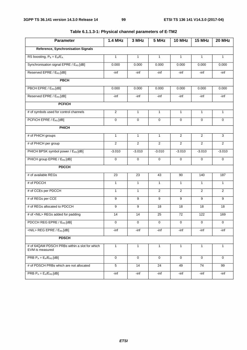
ETSI
ETSI TS 136 141 V14.3.0 (2017-04)993GPP TS 36.141 version 14.3.0 Release 14
Table 6.1.1.3-1: Physical channel parameters of E-TM2
Parameter 1.4 MHz 3 MHz 5 MHz 10 MHz 15 MHz 20 MHz
Reference, Synchronisation Signals
RS boosting, PB = EB/EA 1 1 1 1 1 1
Synchronisation signal EPRE / ERS [dB] 0.000 0.000 0.000 0.000 0.000 0.000
Reserved EPRE / ERS [dB] -inf -inf -inf -inf -inf -inf
PBCH
PBCH EPRE / ERS [dB] 0.000 0.000 0.000 0.000 0.000 0.000
Reserved EPRE / ERS [dB] -inf -inf -inf -inf -inf -inf
PCFICH
# of symbols used for control channels 2 1 1 1 1 1
PCFICH EPRE / ERS [dB] 0 0 0 0 0 0
PHICH
# of PHICH groups 1 1 1 2 2 3
# of PHICH per group 2 2 2 2 2 2
PHICH BPSK symbol power / ERS [dB] -3.010 -3.010 -3.010 -3.010 -3.010 -3.010
PHICH group EPRE / ERS [dB] 0 0 0 0 0 0
PDCCH
# of available REGs 23 23 43 90 140 187
# of PDCCH 1 1 1 1 1 1
# of CCEs per PDCCH 1 1 2 2 2 2
# of REGs per CCE 9 9 9 9 9 9
# of REGs allocated to PDCCH 9 9 18 18 18 18
# of <NIL> REGs added for padding 14 14 25 72 122 169
PDCCH REG EPRE / ERS [dB] 0 0 0 0 0 0
<NIL> REG EPRE / ERS [dB] -inf -inf -inf -inf -inf -inf
PDSCH
# of 64QAM PDSCH PRBs within a slot for which EVM is measured
1 1 1 1 1 1
PRB PA = EA/ERS [dB] 0 0 0 0 0 0
# of PDSCH PRBs which are not allocated 5 14 24 49 74 99
PRB PA = EA/ERS [dB] -inf -inf -inf -inf -inf -inf

ETSI
ETSI TS 136 141 V14.3.0 (2017-04)1003GPP TS 36.141 version 14.3.0 Release 14
Table 6.1.1.3-2: Numbers ( PRBn ) of the allocated PRB (64QAM) (FDD)
Subframe 0
Subframe 1
Subframe 2
Subframe 3
Subframe 4
Subframe 5
Subframe 6
Subframe 7
Subframe 8
Subframe 9
1.4 MHz
4 1 1 2 5 3 0 0 5 4
3 MHz
13 11 13 5 9 14 6 13 0 1
5 MHz
8 17 21 8 22 2 9 14 0 13
10 MHz
16 36 19 26 42 30 17 48 9 0
15 MHz
32 46 18 72 22 4 31 58 27 3
20 MHz
63 34 44 7 94 2 97 19 56 32
Table 6.1.1.3-3: Numbers ( PRBn ) of the allocated PRB (64QAM) (TDD)
Frame1 Subframe 0
Subframe 1
Subframe 5
Subframe 6
Subframe 7
Subframe 8
Subframe 9
1.4 MHz 4 5 5 2 0 0 3 3 MHz 10 14 12 5 0 1 7 5 MHz 17 24 21 8 1 2 12 10 MHz 35 49 42 17 2 4 25 15 MHz 53 74 63 26 3 6 38 20 MHz 71 99 85 35 4 8 51
Frame2 Subframe 0
Subframe 1
Subframe 5
Subframe 6
Subframe 7
Subframe 8
Subframe 9
1.4 MHz 4 5 2 1 3 1 4 3 MHz 11 14 5 3 8 3 11 5 MHz 18 23 8 5 13 5 19 10 MHz 37 46 17 10 26 11 38 15 MHz 56 70 25 15 40 17 57 20 MHz 75 93 34 20 53 23 76
6.1.1.3a E-UTRA Test Model 2a (E-TM2a)
This model shall be used for tests on:
- Total power dynamic range (lower OFDM symbol power limit at min power),
- EVM of single 256QAM PRB allocation (at min power)
- Frequency error (at min power)
Physical channel parameters and numbers of the allocated PRB are defined in Tables 6.1.1.3-1, 6.1.1.3-2, 6.1.1.3-3, with all 64QAM PDSCH PRBs replaced by 256QAM PDSCH PRBs.
6.1.1.4 E-UTRA Test Model 3.1 (E-TM3.1)
This model shall be used for tests on:
- Output power dynamics
- Total power dynamic range (upper OFDM symbol power limit at max power with all 64QAM PRBs allocated)
- Transmitted signal quality

ETSI
ETSI TS 136 141 V14.3.0 (2017-04)1013GPP TS 36.141 version 14.3.0 Release 14
- Frequency error
- EVM for 64QAM modulation (at max power)
Table 6.1.1.4-1: Physical channel parameters of E-TM3.1
Parameter 1.4 MHz 3 MHz 5 MHz 10 MHz 15 MHz 20 MHz Reference, Synchronisation Signals
RS boosting, PB = EB/EA 1 1 1 1 1 1
Synchronisation signal EPRE / ERS [dB] 0.000 0.000 0.000 0.000 0.000 0.000
Reserved EPRE / ERS [dB] -inf -inf -inf -inf -inf -inf
PBCH PBCH EPRE / ERS [dB] 0.000 0.000 0.000 0.000 0.000 0.000
Reserved EPRE / ERS [dB] -inf -inf -inf -inf -inf -inf
PCFICH # of symbols used for control channels 2 1 1 1 1 1
PCFICH EPRE / ERS [dB] 3.222 0 0 0 0 0
PHICH # of PHICH groups 1 1 1 2 2 3
# of PHICH per group 2 2 2 2 2 2
PHICH BPSK symbol power / ERS [dB] -3.010 -3.010 -3.010 -3.010 -3.010 -3.010
PHICH group EPRE / ERS [dB] 0 0 0 0 0 0
PDCCH # of available REGs 23 23 43 90 140 187
# of PDCCH 2 2 2 5 7 10
# of CCEs per PDCCH 1 1 2 2 2 2
# of REGs per CCE 9 9 9 9 9 9
# of REGs allocated to PDCCH 18 18 36 90 126 180
# of <NIL> REGs added for padding 5 5 7 0 14 7
PDCCH REG EPRE / ERS [dB] 0.792 2.290 1.880 1.065 1.488 1.195
<NIL> REG EPRE / ERS [dB] -inf -inf -inf -inf -inf -inf
PDSCH # of 64QAM PDSCH PRBs within a slot for which EVM is measured
6 15 25 50 75 100
PRB PA = EA/ERS [dB] 0 0 0 0 0 0
# of PDSCH PRBs within a slot for which EVM is not measured (used for power balancing only)
0 0 0 0 0 0
PRB PA = EA/ERS [dB] n.a. n.a. n.a. n.a. n.a. n.a.
6.1.1.4a E-UTRA Test Model 3.1a (E-TM3.1a)
This model shall be used for tests on:
- Output power dynamics
- Total power dynamic range (upper OFDM symbol power limit at max power with all 256QAM PRBs allocated)
- Transmitted signal quality
- Frequency error
- EVM for 256QAM modulation (at max power)
Physical channel parameters are defined in Table 6.1.1.4-1, with all 64QAM PDSCH PRBs replaced by 256QAM PDSCH PRBs.
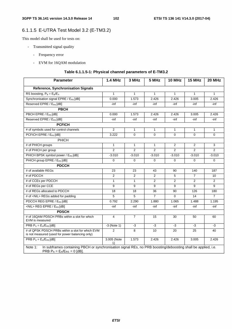
ETSI
ETSI TS 136 141 V14.3.0 (2017-04)1023GPP TS 36.141 version 14.3.0 Release 14
6.1.1.5 E-UTRA Test Model 3.2 (E-TM3.2)
This model shall be used for tests on:
- Transmitted signal quality
- Frequency error
- EVM for 16QAM modulation
Table 6.1.1.5-1: Physical channel parameters of E-TM3.2
Parameter 1.4 MHz 3 MHz 5 MHz 10 MHz 15 MHz 20 MHz
Reference, Synchronisation Signals
RS boosting, PB = EB/EA 1 1 1 1 1 1
Synchronisation signal EPRE / ERS [dB] 0.000 1.573 2.426 2.426 3.005 2.426
Reserved EPRE / ERS [dB] -inf -inf -inf -inf -inf -inf
PBCH PBCH EPRE / ERS [dB] 0.000 1.573 2.426 2.426 3.005 2.426
Reserved EPRE / ERS [dB] -inf -inf -inf -inf -inf -inf
PCFICH # of symbols used for control channels 2 1 1 1 1 1
PCFICH EPRE / ERS [dB] 3.222 0 0 0 0 0
PHICH # of PHICH groups 1 1 1 2 2 3
# of PHICH per group 2 2 2 2 2 2
PHICH BPSK symbol power / ERS [dB] -3.010 -3.010 -3.010 -3.010 -3.010 -3.010
PHICH group EPRE / ERS [dB] 0 0 0 0 0 0
PDCCH # of available REGs 23 23 43 90 140 187
# of PDCCH 2 2 2 5 7 10
# of CCEs per PDCCH 1 1 2 2 2 2
# of REGs per CCE 9 9 9 9 9 9
# of REGs allocated to PDCCH 18 18 36 90 126 180
# of <NIL> REGs added for padding 5 5 7 0 14 7
PDCCH REG EPRE / ERS [dB] 0.792 2.290 1.880 1.065 1.488 1.195
<NIL> REG EPRE / ERS [dB] -inf -inf -inf -inf -inf -inf
PDSCH # of 16QAM PDSCH PRBs within a slot for which EVM is measured
4 7 15 30 50 60
PRB PA = EA/ERS [dB] -3 (Note 1) -3 -3 -3 -3 -3
# of QPSK PDSCH PRBs within a slot for which EVM is not measured (used for power balancing only)
2 8 10 20 25 40
PRB PA = EA/ERS [dB] 3.005 (Note 1)
1.573 2.426 2.426 3.005 2.426
Note 1: In subframes containing PBCH or synchronisation signal REs, no PRB boosting/deboosting shall be applied, i.e. PRB PA = EA/ERS = 0 [dB].

ETSI
ETSI TS 136 141 V14.3.0 (2017-04)1033GPP TS 36.141 version 14.3.0 Release 14
Table 6.1.1.5-2: Numbers ( PRBn ) of the 16QAM PRBs (FDD)
Subframe 0
Subframe 1
Subframe 2
Subframe 3
Subframe 4
Subframe 5
Subframe 6
Subframe 7
Subframe 8
Subframe 9
1.4 MHz
1 3 4 5 1 2 3 5 0 1 3 4 1 2 3 5 0 2 3 5 0 1 2 4 0 1 2 5 0 2 4 5 1 2 3 5 0 1 3 5
3 MHz
0 1 2 3 11 12 13
0 3 4 10 11 12 13
0 2 3 5 6 11 13
0 1 4 5 7 10 12
0 2 3 4 9 10 13
0 1 2 3 11 12 14
4 5 6 8 11 13 14
2 5 6 9 12 13 14
0 3 4 7 8 9 11
1 2 3 4 5 11 12
5 MHz
0 1 3 4 6 7 8 16 17 18 19 20 21 23 24
0 1 2 3 4 5 6 9 10 12 13 17 18 20 24
0 1 2 3 7 8 9 10 12 13 14 19 20 23 24
0 5 6 8 10 11 12 13 15 17 18 20 21
22 24
0 1 2 4 6 7 12 13
14 15 16 17 22 23
24
0 1 2 3 4 6 7 8 16 17 18 21 22 23 24
1 3 4 5 7 9 10 11
12 13 14 15 21 22
24
0 1 2 3 4 7 8 10 13 14 18 19 20 21 24
1 4 8 9 10 11 12 13 15 16 18 20 22
23 24
1 2 3 4 5 6 9 10 11 12 13 16 17 21 23
10 MHz
1 2 3 4 5 6 7 8 9 10 11 15 16 17 20 21 28 30 31 32 33 35 36 39 40 42 44 46
47 48
0 1 2 4 5 6 7 9 10 11 13 15 18 20 21 22 24 25 27 28 29 34 35 36 37 40 43 44 46 49
0 1 3 4 5 6 7 11 12 14 17 18 19 20 21 22 24 25 26 27 28 29 31 32 34 38 41 42 45 49
0 1 2 3 5 6 8 12 14 15 16 17 18 22 23 26 28 29 30 32 34 35 38 39 40 41 42 45 46 47
0 3 6 7 8 9 10 12
13 15 16 17 18 21 23 25 28 31 33 37 38 39 41 42 44 45 46 47 48
49
0 2 3 4 5 7 9 10 11 12 13 14 15 19 20 28 29 30 31 34 36 37 38 39 40 42 44 45 48 49
0 1 3 4 5 6 8 9 10 13 14 16 17 18 19 20 21 23 24 29 30 31 32 35 37 38 39 40 47 48
0 1 2 3 4 5 6 7 9 10 12 14 16 17 18 19 22 24 25 26 27 28 30 31 32 34 37 42
45 48
2 5 7 8 9 10 11 14 15 16 17 21 22 27 28 29 30 31 32 34 35 37 38 41 42 43 44 46 48
49
1 3 6 9 11 13 15 16 17 18 21 24 25 26 27 28 29 30 32 34 37 38 39 40 41 42 45 47
48 49 15
MHz 0 1 2 3 5 6 7 8 9 12 14 16 17 18 19 20 21 23 24 25 26 28 29 30 31 32 33 41 42 45 47 48 49 50 52 53 56 57 60 62 63 64 65 67 68 69 70 71 72
73
0 1 2 3 4 5 6 7 8 11 18 20 21 24 25 26 27 29 30 31 33 36 37 38 39 40 43 45 46 47 48 49 50 51 53 54 55 57 58 59 60 61 65 67 68 69 70 71 73
74
1 2 3 4 9 11 12 13 14 15 17 18 20 21 22 24 25 26 28 29 31 32 33 34 40 42 43 44 45 46 47 48 50 51 52 54 56 58 59 60 61 62 63 64 68 70 71 72 73 74
2 3 4 6 7 9 11 12
14 15 17 18 20 22 24 25 27 28 29 30 31 33 34 35 38 39 40 42 43 45 46 47 48 49 55 56 59 60 61 62 63 65 66 67 68 69 70 71 73 74
2 4 5 6 8 10 13 15 16 17 18 20 22 24 25 26 27 28 29 30 31 32 33 34 35 38 40 41 44 45 46 47 48 50 51 52 53 54 56 59 60 63 64 67 69 70 71 72 73 74
0 2 3 4 5 7 8 11 12 14 16 18 20 22 23 24 25 27 28 29 30 31 33 42 43 45 46 47 48 49 50 51 53 54 56 58 60 61 62 63 64 65 66 67 68 69 70 71
72 73
0 1 2 3 9 11 12 14 15 17 18 20 23 25 26 28 29 30 31 32 33 36 37 38 39 41 42 43 45 46 50 52 53 54 57 58 59 60 61 62 63 64 65 67 68 70 71 72 73 74
0 1 3 4 5 6 7 8 11 12 14 19 20 21 23 24 26 27 28 30 31 33 34 35 38 40 41 42 44 45 46 49 51 52 53 54 55 58 59 60 61 62 63 65 67 69 70 71
72 73
0 1 2 3 7 8 9 10 12 13 14 15 17 18 19 21 22 23 24 25 26 27 28 29 32 33 34 36 37 39 40 43 46 47 48 49 50 53 54 56 61 62 63 66 68 69 71 72
73 74
0 1 3 7 8 11 13 14 16 18 19 20 21 22 23 25 27 28 29 30 32 34 35 36 40 41 42 43 44 45 46 47 48 50 51 53 54 55 57 59 61 62 63 64 66 67 68 69 70 71
20 MHz
0 1 4 6 7 8 9 10 11 13 14 15 16 20 21 22 23 25 26 28 29 30 31 32 33 34 36 39 41 42 44 45 54 56 57 58 60 61 63 66 67 68 72 75 76 77 79 81 82 84 85 87 88 91 92 94 95 97 98 99
1 3 5 6 7 9 10 13
17 19 20 21 22 23 24 25 26 27 28 30 32 33 34 35 36 39 41 47 48 49 50 51 53 54 55 57 58 59 60 61 64 65 67 68 75 76 77 79 80 81 83 84 86 87 89 90 91 93 95
99
0 1 2 3 6 8 10 11
15 16 17 19 21 22 23 25 26 28 29 30 32 33 35 38 39 40 41 42 43 44 46 49 51 52 53 54 57 59 60 62 63 64 65 67 69 71 72 73 76 79 81 84 86 88 89 90 92 93 94
99
5 6 7 9 10 12 14 15 16 17 21 22 23 24 27 28 29 30 31 33 34 35 36 37 39 41 44 45 47 49 50 53 54 55 56 57 59 64 65 66 68 70 72 75 76 77 80 81 84 85 86 87 90 91 92 94 95 97
98 99
0 2 3 4 5 6 7 11 12 14 15 17 19 21 22 24 26 32 36 37 40 42 43 44 47 48 49 50 51 54 56 57 60 62 63 65 66 67 70 71 73 76 77 78 79 81 82 83 84 85 86 87 89 91 94 95 96 97 98 99
1 2 5 6 8 9 11 12
13 15 21 22 25 26 27 28 29 30 31 32 34 35 38 39 40 41 43 44 45 46 53 57 58 59 61 62 63 64 65 66 68 69 71 72 73 75 77 78 80 82 83 84 85 86 93 94 95 96 97
99
0 1 2 3 5 8 9 10 12 13 14 16 22 25 26 27 28 29 31 32 33 34 36 37 38 39 43 44 45 46 48 49 52 53 55 59 61 62 63 64 70 71 72 73 74 75 77 78 80 81 82 84 86 89 90 91 93 97 98 99
0 1 3 4 5 7 8 10 11 15 18 19 20 21 26 27 29 30 31 33 35 37 38 39 40 41 43 44 45 46 47 48 49 50 52 53 55 56 58 60 62 64 65 66 67 69 70 71 72 73 74 81 83 84 86 92 93 94 96 98
2 3 4 5 7 9 11 13
15 16 17 21 23 24 25 27 28 29 31 33 35 36 40 42 43 44 45 46 48 49 51 52 53 54 55 56 57 59 61 63 64 65 68 71 76 77 78 81 82 83 84 85 86 87 90 91 93 94 98
99
0 3 4 6 7 8 10 11
13 16 18 21 22 23 25 26 28 29 32 35 36 37 38 43 44 46 47 48 49 53 54 57 58 59 60 61 64 66 67 68 69 70 72 76 77 78 80 81 82 83 84 86 87 88 89 91 92 94 95
96

ETSI
ETSI TS 136 141 V14.3.0 (2017-04)1043GPP TS 36.141 version 14.3.0 Release 14
Table 6.1.1.5-3: Numbers ( PRBn ) of the 16QAM PRBs (TDD)
Frame1 Subframe 0 Subframe 1 Subframe 5 Subframe 6 Subframe 7 Subframe 8 Subframe 9 1.4 MHz 0 3 4 5 1 2 3 4 0 1 2 4 0 1 3 4 0 2 4 5 2 3 4 5 1 2 4 5 3 MHz 0 1 2 3 11 12
14 0 1 2 3 11 12
13 0 1 2 3 11 12
14 0 1 2 3 11 12
13 1 2 7 8 10 13
14 2 3 4 6 8 13
14 0 3 6 8 9 10
14 5 MHz 1 2 3 4 5 6 7 8
17 18 19 20 21 23 24
0 2 3 4 5 6 7 8 17 18 19 20
21 22 24
1 2 3 4 5 6 7 8 16 17 18 19
20 21 22
1 2 3 4 5 6 7 8 16 17 20 21
22 23 24
1 2 4 6 7 8 9 11 14 15 16 18 21 23 24
0 2 3 5 6 7 10 13 15 16 17 19 20 21 24
0 2 3 4 6 7 8 13 14 15 16 19 21 23 24
10 MHz 1 2 3 4 6 7 9 10 11 13 14 15 17 18 19 28 29 30 34 35 37 38 39 41 42 44 46
47 48 49
2 3 4 5 6 7 8 9 10 11 12 13 14 16 17 18 19 21 30 32 34 35 36 37 39 40 41 43
45 48
2 4 5 6 7 8 9 11 12 13 14 16 18 20 21 28 29 30 31 32 33 34 41 43 44 45 46
47 48 49
1 4 5 6 7 8 11 12 13 14 15 17 19 20 21 28 29 30 31 32 34 37 38 41 42 44 46
47 48 49
0 1 2 5 6 7 8 11 13 14 15 16 18 20 21 24 25 27 30 32 34 35 37 38 40 41 43
46 47 49
2 4 5 6 7 9 10 11 15 18 19 20 21 24 25 26 28 29 30 32 33 35 36 38 40 41 43
44 48 49
2 5 6 7 8 9 10 11 14 15 16 18 19 20 21 23 27 28 30 32 33 34 37 41 42 44 45
46 47 49 15 MHz 1 3 4 5 6 7 8 9
10 11 13 15 16 17 19 20 21 22 23 24 25 26 27 28 29 33 42 44 45 46 51 52 53 55 56 57 58 59 60 61 62 63 64 65 66 70 71 72
73 74
2 3 4 6 7 8 9 10 11 12 13 14 15 16 18 19 20 22 24 25 27 28 30 31 32 41 42 43 44 45 46 48 49 50 51 52 55 58 61 62 63 65 66 67 68 69 70
71 73 74
0 1 2 3 6 7 8 9 10 11 12 13 16 17 18 19 20 21 22 23 24 26 27 28 30 31 32 41 43 45 46 47 48 51 53 55 56 57 58 61 62 63 64 65 66 69 70 71
73 74
3 7 8 9 10 11 12 13 14 15 16 17 22 23 24 27 28 29 30 31 32 41 42 43 45 46 48 49 50 53 54 55 56 57 58 60 61 62 63 64 65 66 67 68 69 70 71 72 73 74
0 1 2 3 4 6 9 10 11 13 14 15 16 17 20 21 22 23 24 25 28 29 34 37 43 44 46 47 48 49 51 52 53 54 55 57 59 61 62 63 64 65 67 68 69 70 71
72 73 74
0 1 3 4 5 8 9 10 11 12 13 14 15 16 19 20 22 24 25 26 27 28 31 32 33 34 35 36 37 38 40 42 43 44 45 46 47 48 50 51 52 55 56 59 60 61 66
67 69 74
1 3 4 5 7 8 9 10 12 13 14 15 16 17 19 20 21 23 26 27 28 29 30 31 32 33 34 36 37 38 39 42 43 44 45 46 52 53 57 58 59 60 62 63 64 65 69
71 72 73 20 MHz 2 4 5 6 7 8 9
10 11 12 13 14 17 18 19 20 21 22 23 25 27 28 29 31 32 33 34 35 37 38 39 43 44 46 53 56 58 60 61 68 69 70 71 73 74 75 76 78 79 80 82 83 85 86 87 88 93 95 97
99
2 4 5 8 9 10 11 12 13 14 16 17 18 19 22 24 25 26 27 29 30 32 33 36 37 38 40 41 42 43 45 46 53 54 55 57 58 60 62 64 65 66 67 68 69 74 78 82 83 84 86 88 89 90 91 92 93 95
97 99
0 2 3 4 9 10 11 12 13 14 15 17 18 21 22 23 24 25 26 27 28 30 31 32 35 36 37 38 40 41 42 43 53 54 55 57 60 61 63 64 65 66 68 70 74 76 77 81 82 84 85 87 88 89 93 94 95 97
98 99
1 4 9 10 12 13 14 15 17 18 19 20 21 22 23 29 30 31 32 33 36 37 39 40 41 42 43 46 53 54 55 56 57 58 60 61 64 66 68 69 71 72 73 74 75 80 82 83 84 86 87 89 90 92 93 94 95 96
98 99
0 1 3 4 5 7 8 12 13 14 15 17 19 20 22 23 25 26 28 30 31 33 35 37 38 39 41 45 48 49 50 51 58 59 62 63 65 67 68 69 70 71 72 73 75 76 78 82 84 85 86 89 90 91 92 93 94 96 97
98
0 2 4 5 6 7 11 12 13 14 16 17 18 19 20 21 23 27 28 30 31 32 35 37 38 40 43 44 45 46 47 50 51 53 56 57 58 59 60 61 62 63 64 65 68 70 71 73 77 79 80 82 85 87 89 92 95 96 97
98
1 3 4 5 6 7 9 10 13 16 18 20 21 24 25 26 27 28 30 31 32 35 37 38 41 42 43 44 46 47 48 50 51 52 53 54 57 59 60 61 62 64 67 70 71 73 76 77 78 79 81 82 84 86 87 88 91 95 98
99
Frame2 Subframe 0 Subframe 1 Subframe 5 Subframe 6 Subframe 7 Subframe 8 Subframe 9
1.4 MHz 0 2 4 5 1 2 4 5 0 1 3 4 0 2 3 5 0 1 2 4 1 2 3 4 1 2 3 5 3 MHz 0 1 2 3 12 13
14 0 1 2 3 11 12 13
1 2 3 11 12 13 14
0 1 2 11 12 13 14
2 4 7 8 9 10 11
0 1 3 4 5 13 14
0 4 6 8 9 11 12
5 MHz 0 2 3 4 5 6 7 16 17 18 19 20 21 22 23
0 1 2 3 4 5 7 8 16 17 18 19 20 23 24
1 2 3 4 5 7 8 16 17 18 20 21 22 23 24
0 1 3 4 5 7 8 16 17 18 19 20 21 22 24
0 1 3 6 7 9 12 14 17 18 20 21 22 23 24
2 3 4 5 6 7 9 11 12 14 15 17 18 21 24
0 1 3 4 5 8 10 11 12 14 16 17 20 22 24
10 MHz 0 1 2 6 7 8 9 11 13 14 15 16 19 29 30 32 34 35 36 37 38 39 41 42 43 44 45 47 48 49
0 2 3 4 6 7 8 9 10 11 12 15 16 17 18 19 20 29 31 33 34 35 36 37 42 45 46 47 48 49
0 1 2 3 5 6 7 8 9 10 13 14 15 16 18 20 21 28 29 30 31 32 34 35 39 40 41 42 44 46
1 2 3 4 5 6 8 9 10 11 12 13 15 16 17 18 19 21 30 35 38 39 40 41 42 43 46 47 48 49
1 2 3 5 6 13 14 15 16 17 19 20 23 25 26 27 29 30 31 32 33 35 38 39 40 41 43 44 47 49
0 1 2 5 9 12 13 14 16 17 18 22 25 26 27 28 29 30 31 33 35 36 38 39 41 42 44 45 47 49
0 1 2 3 4 5 7 8 9 10 12 13 14 15 16 18 22 27 28 29 30 31 32 33 34 42 43 45 46 49
15 MHz 0 1 2 3 4 5 6 7 8 10 11 14 15 16 18 19 20 21 23 24 25 26 27 28 31 32 33 41 43 44 45 46 47 48 50 52 53 55 57 58 59 61 63 65 66 67 68 69 71 74
1 2 3 4 5 6 7 8 9 10 11 13 14 15 16 18 20 21 22 23 27 28 29 30 33 42 43 45 46 47 49 50 51 54 55 56 58 59 60 61 64 65 66 68 69 70 71 72 73 74
0 1 2 4 5 6 7 8 9 10 11 12 13 14 15 16 18 20 22 24 25 26 29 32 33 44 45 46 49 50 51 52 55 56 57 58 59 60 61 63 64 65 66 68 69 70 71 72 73 74
0 1 2 3 4 5 6 7 8 9 10 11 13 14 15 16 17 18 19 21 23 24 26 29 30 33 41 42 45 46 47 49 50 51 53 54 55 56 57 58 60 62 63 66 67 69 71 72 73 74
1 3 4 5 6 7 9 10 11 12 14 15 16 17 18 19 20 21 22 24 26 29 30 32 33 34 35 36 38 39 41 42 44 45 47 48 49 50 52 55 56 57 61 62 63 69 70 71 73 74
1 3 4 6 7 8 10 11 13 14 15 21 22 23 24 26 27 28 29 30 31 32 35 39 40 43 44 45 46 47 48 49 50 51 52 53 54 55 56 57 58 59 60 63 64 65 66 68 71 74
0 1 2 5 6 7 10 11 12 16 17 18 19 22 23 25 27 28 29 30 31 33 34 35 36 37 39 40 43 45 46 47 48 49 50 52 54 55 56 58 61 62 63 64 66 67 68 69 71 73
20 MHz 0 1 2 3 4 5 7 8 9 10 11 15 17
0 2 3 4 7 8 10 11 12 13 14
0 1 2 4 5 6 7 10 11 12 13
0 1 2 3 4 6 7 8 9 12 13 15 16
0 1 2 4 6 8 9 10 11 14 15
0 1 2 3 7 8 9 13 15 16 21
3 4 6 7 9 10 11 12 13 14

ETSI
ETSI TS 136 141 V14.3.0 (2017-04)1053GPP TS 36.141 version 14.3.0 Release 14
19 20 21 24 26 27 28 29 31 32 33 34 36 37 44 45 54 56 57 58 59 60 61 63 65 67 68 69 70 73 77 79 83 85 86 87 88 89 90 91 92 93 94 95 96 98 99
15 16 17 18 19 20 22 24 25 27 30 35 37 39 41 42 44 53 56 57 59 61 62 63 66 67 69 70 73 74 75 76 77 78 79 80 81 82 84 85 86 88 89 90 91 92 94 96 98
14 15 16 18 19 20 21 23 24 25 29 32 33 34 40 42 43 44 45 46 53 54 55 57 59 60 61 62 63 67 68 71 72 73 75 77 81 82 84 85 87 91 92 93 95 96 97 98 99
18 19 20 22 24 25 27 28 29 30 32 35 39 40 42 43 44 57 59 60 61 63 64 65 66 67 68 69 70 72 73 74 75 76 81 82 83 84 88 89 90 92 94 95 97 98 99
18 19 20 21 25 29 31 32 34 36 37 38 40 41 42 47 52 53 54 57 58 59 60 62 63 64 65 67 68 69 70 71 73 74 75 76 77 78 79 80 84 85 86 87 88 90 92 95 99
23 24 25 29 30 31 33 34 36 37 38 39 40 41 42 44 45 46 47 48 49 52 53 57 60 62 63 64 65 66 69 72 73 74 75 77 81 82 83 84 86 88 89 90 91 92 93 95 97
15 17 19 22 23 25 26 27 33 34 37 39 40 41 43 45 46 47 48 49 50 53 55 56 58 60 61 62 63 65 69 71 72 73 74 76 77 78 79 80 82 83 85 87 91 92 94 95 96 99
6.1.1.6 E-UTRA Test Model 3.3 (E-TM3.3)
This model shall be used for tests on:
- Transmitted signal quality
- Frequency error
- EVM for QPSK modulation
Table 6.1.1.6-1: Physical channel parameters of E-TM3.3
Parameter 1.4 MHz 3 MHz 5 MHz 10 MHz 15 MHz 20 MHz Reference, Synchronisation Signals
RS boosting, PB = EB/EA 1 1 1 1 1 1
Synchronisation signal EPRE / ERS [dB] 0.000 2.189 2.580 2.427 2.477 2.427
Reserved EPRE / ERS [dB] -inf -inf -inf -inf -inf -inf
PBCH
PBCH EPRE / ERS [dB] 0.000 2.189 2.580 2.427 2.477 2.427
Reserved EPRE / ERS [dB] -inf -inf -inf -inf -inf -inf
PCFICH
# of symbols used for control channels 2 1 1 1 1 1
PCFICH EPRE / ERS [dB] 3.222 0 0 0 0 0
PHICH
# of PHICH groups 1 1 1 2 2 3
# of PHICH per group 2 2 2 2 2 2
PHICH BPSK symbol power / ERS [dB] -3.010 -3.010 -3.010 -3.010 -3.010 -3.010
PHICH group EPRE / ERS [dB] 0 0 0 0 0 0
PDCCH
# of available REGs 23 23 43 90 140 187
# of PDCCH 2 2 2 5 7 10
# of CCEs per PDCCH 1 1 2 2 2 2
# of REGs per CCE 9 9 9 9 9 9
# of REGs allocated to PDCCH 18 18 36 90 126 180
# of <NIL> REGs added for padding 5 5 7 0 14 7

ETSI
ETSI TS 136 141 V14.3.0 (2017-04)1063GPP TS 36.141 version 14.3.0 Release 14
PDCCH REG EPRE / ERS [dB] 0.792 2.290 1.880 1.065 1.488 1.195
<NIL> REG EPRE / ERS [dB] -inf -inf -inf -inf -inf -inf
PDSCH
# of QPSK PDSCH PRBs within a slot for which EVM is measured
3 7 13 25 38 50
PRB PA = EA/ERS [dB] -6 (*) -6 -6 -6 -6 -6
# of 16QAM PDSCH PRBs within a slot for which EVM is not measured (used for power balancing only)
3 8 12 25 37 50
PRB PA = EA/ERS [dB] 2.427 (*) 2.189 2.580 2.427 2.477 2.427
Note 1: In subframes containing PBCH or synchronisation signal REs, no PRB boosting/deboosting shall be applied, i.e. PRB PA = EA/ERS = 0 [dB].
Table 6.1.1.6-2: Numbers ( PRBn ) of the QPSK PRBs (FDD)
Subframe 0
Subframe 1
Subframe 2
Subframe 3
Subframe 4
Subframe 5
Subframe 6
Subframe 7
Subframe 8
Subframe 9
1.4 MHz
2 3 5 1 2 3 0 1 3 1 2 3 2 3 5 1 2 5 0 2 5 0 2 5 1 2 5 1 3 5
3 MHz
0 1 2 3 11 12 13
0 3 4 10 11 12 13
0 2 3 5 6 11 13
0 1 4 5 7 10 12
0 2 3 4 9 10 13
0 1 2 3 11 12 14
4 5 6 8 11 13 14
2 5 6 9 12 13 14
0 3 4 7 8 9 11
1 2 3 4 5 11 12
5 MHz
0 1 3 6 7 8 16 17 18 20 21 23 24
0 1 2 4 5 6 9 10 12 17 18 20 24
0 1 2 3 9 10 12 13 14 19 20 23 24
0 5 6 8 10 12 13 15 17 18 20 21 24
0 2 4 6 7 12 13 15 16 17 22 23 24
0 1 2 3 4 6 7 8 16 18 21 22 24
1 3 4 5 7 9 10 11 12 15 21 22 24
0 1 2 3 4 7 10 14 18 19 20 21 24
1 4 8 9 10 11 12 13 15 16 18 20 23
1 2 3 4 5 6 9 10 11 13 16 17 23
10 MHz
1 2 3 5 6 7 8 9 10 11 15 16 20 28 31 32 33 35 36 39 40 42 46 47 48
1 2 4 5 6 7 9 11 15 18 20 21 22 24 25 27 29 34 35 36 37 40 44 46 49
0 3 5 6 11 12 14 17 18 19 20 21 22 24 25 26 27 28 29 31 34 38 41 42 49
0 1 2 3 5 6 8 14 16 18 22 23 26 28 30 32 34 38 39 40 41 42 45 46 47
0 3 6 7 8 9 10 12 13 16 17 18 21 23 25 31 33 37 41 42 45 46 47 48 49
0 2 3 4 5 7 9 10 11 12 13 15 19 20 28 29 30 31 34 36 37 42 44 48 49
0 1 4 5 6 8 9 10 13 16 17 18 19 20 21 24 29 30 31 32 35 37 38 39 47
0 2 3 4 5 6 7 9 10 12 16 17 18 19 22 24 25 26 30 31 34 37 42 45 48
5 7 8 9 14 15 16 21 22 27 28 30 31 32 34 35 37 38 41 42 43 44 46 48 49
3 9 11 13 16 17 18 21 24 27 28 29 30 32 34 37 38 39 40 41 42 45 47 48 49
15 MHz
0 1 2 3 5 6 7 8 9 12 16 17 18 19 20 21 23 24 25 28 29 30 31 32 33 42 47 48 49 53 60 63 65 67 68 70 71 73
0 1 3 4 5 6 7 8 11 18 20 21 24 25 26 27 29 30 31 38 46 47 49 50 51 53 54 55 57 59 60 61 67 68 69 70 73 74
2 11 12 13 15 17 18 21 22 24 25 26 29 31 32 33 34 40 42 45 46 47 50 51 52 54 58 59 60 61 62 63 64 68 70 71 72 74
2 3 4 6 7 9 11 12 15 17 20 24 27 30 33 34 35 38 39 42 43 45 46 48 49 55 56 59 60 61 62 65 67 69 70 71 73 74
4 5 6 8 10 13 17 22 25 26 27 28 29 30 31 32 33 34 35 38 41 44 46 48 50 52 53 54 56 59 60 64 67 69 70 71 73 74
0 2 3 4 7 8 11 14 18 20 23 24 25 27 29 42 43 45 46 47 48 49 50 51 54 56 60 62 63 65 66 67 68 69 70 71 72 73
1 2 9 11 14 15 18 25 26 28 29 30 31 32 33 36 37 38 39 41 43 45 46 50 53 54 58 59 60 62 63 65 67 68 70 71 72 73
3 4 6 7 8 11 12 19 20 23 24 26 27 28 30 33 34 35 40 41 42 46 49 51 53 54 58 59 60 61 62 65 67 69 70 71 72 73
0 1 2 3 7 8 9 10 13 14 15 17 18 19 22 23 24 25 26 27 28 32 36 37 39 46 47 50 53 56 61 62 63 68 69 71 73 74
0 3 7 8 11 13 14 16 18 19 23 25 27 28 29 30 32 35 41 42 44 46 47 48 50 53 55 57 59 61 62 64 66 67 68 69 70 71
20 MHz
0 1 4 6 10 13 14 15 16 20 22 23 25 26 28 29 30 31 32 33 36 39 41 42 44 45 54 56 57 60 63 66 67 68 72 76 77 79 82 84 85 87 88 91 92 94 95 97 98 99
1 3 7 9 10 13 19 20 21 22 23 24 25 26 27 30 33 34 35 36 47 48 49 50 51 53 54 55 57 59 60 61 64 65 67 68 75 76 77 80 81 83 84 86 87 89 90 93 95 99
1 2 3 6 8 10 11 15 16 17 19 21 25 26 28 29 30 32 33 35 38 39 40 41 42 43 44 46 49 51 52 54 60 62 63 64 65 69 72 76 79 81 84 86 88 89 90 93 94 99
5 7 9 10 12 14 15 16 21 22 23 24 27 28 29 30 33 34 35 36 37 39 41 44 45 47 49 54 55 56 57 64 66 68 70 72 76 77 80 81 85 86 87 90 91 92 94 95 98 99
2 3 4 5 6 7 14 15 17 19 21 22 24 26 37 40 42 43 44 47 49 51 54 56 57 60 62 63 65 66 67 70 71 73 76 77 78 81 82 83 84 85 86 87 89 94 95 96 97 99
1 2 5 6 8 9 12 13 21 22 25 26 27 28 29 31 32 34 35 39 40 43 45 46 53 57 59 61 62 63 64 66 68 69 71 73 75 77 78 82 83 84 85 86 93 94 95 96 97 99
0 1 2 3 5 8 9 10 12 13 22 25 26 27 29 31 32 33 36 37 38 39 43 45 48 49 52 53 55 59 62 63 64 71 72 73 74 75 77 78 81 82 84 86 89 91 93 97 98 99
0 1 3 4 5 7 10 11 15 18 19 20 21 26 27 29 30 31 33 35 39 40 41 43 44 46 47 49 50 53 55 56 62 64 65 66 67 69 70 71 72 74 83 84 86 92 93 94 96 98
2 3 4 7 9 11 13 15 16 24 25 27 29 31 33 35 36 40 43 44 45 46 49 51 52 53 54 55 56 57 59 63 64 65 68 71 77 78 81 82 83 84 85 86 90 91 93 94 98 99
0 4 6 7 8 10 11 13 16 18 21 22 23 26 29 32 35 36 37 43 44 46 47 48 49 53 54 57 59 60 61 64 66 67 68 69 70 72 76 78 80 81 82 84 87 89 91 92 95 96

ETSI
ETSI TS 136 141 V14.3.0 (2017-04)1073GPP TS 36.141 version 14.3.0 Release 14
Table 6.1.1.6-3: Numbers ( PRBn ) of the QPSK PRBs (TDD)
Frame1 Subframe 0 Subframe 1 Subframe 5 Subframe 6 Subframe 7 Subframe 8 Subframe 9 1.4 MHz 1 3 4 1 4 5 0 1 2 0 2 4 2 4 5 0 3 4 1 2 5 3 MHz 0 1 2 3 11 12
14 0 1 2 3 11 12 13
0 1 2 3 11 12 14
0 1 2 3 11 12 13
1 2 7 8 10 13 14
2 3 4 6 8 13 14
0 3 6 8 9 10 14
5 MHz 1 2 3 5 6 8 17 18 19 20 21 23 24
0 1 2 3 4 5 7 8 17 18 19 20 22
1 2 3 5 6 7 8 17 18 19 20 21 24
1 2 3 4 5 6 8 16 17 19 20 22 23
1 2 3 8 12 13 14 17 20 21 22 23 24
1 4 5 6 7 10 11 13 14 15 16 22 23
1 2 4 6 7 8 9 14 16 18 21 23 24
10 MHz 2 3 4 6 7 10 11 13 15 17 18 19 29 30 34 35 37 38 39 41 42 46 47 48 49
1 3 4 5 6 7 9 10 12 14 16 17 28 30 34 35 36 37 38 39 40 41 43 44 48
2 3 4 6 7 8 9 10 11 13 14 16 18 19 20 21 29 32 34 39 41 43 44 45 46
2 5 8 9 11 12 13 14 16 18 20 21 28 29 30 31 32 33 34 42 44 45 46 47 49
1 4 5 6 7 11 12 13 14 15 17 20 21 26 27 31 32 34 37 38 41 42 46 48 49
0 1 5 6 7 8 11 12 13 15 19 20 26 28 29 30 31 32 37 38 42 43 44 47 49
1 2 5 6 8 11 13 14 15 16 18 20 21 24 25 27 30 32 34 35 37 40 43 46 47
15 MHz 1 3 5 6 9 10 11 13 15 17 20 21 23 24 25 26 27 28 29 33 42 44 45 51 52 53 56 57 58 61 62 63 65 66 70 71 73 74
3 4 5 6 7 8 9 10 13 14 15 16 19 20 21 22 24 25 28 31 32 33 43 45 46 49 51 52 55 58 59 60 61 62 64 66 67 72
3 4 7 8 10 11 12 13 14 16 18 19 20 22 24 25 27 28 30 32 41 42 43 44 45 46 48 50 51 62 65 67 68 69 70 71 73 74
2 6 7 8 9 10 11 13 16 17 18 19 20 21 22 23 26 30 31 41 43 45 46 47 48 51 55 57 58 62 63 64 65 69 70 71 73 74
0 1 2 3 7 8 9 10 11 12 17 19 21 22 23 24 27 28 30 31 32 37 40 41 45 48 51 53 55 56 57 58 61 63 65 66 70 73
3 7 10 11 13 15 16 17 23 27 29 30 31 32 35 36 37 40 42 43 45 46 48 49 50 53 54 57 60 62 64 65 66 67 68 69 72 74
1 3 8 9 11 12 13 14 15 17 22 23 24 25 28 29 30 31 34 37 40 41 42 46 48 49 51 54 55 56 61 62 63 67 70 71 73 74
20 MHz 2 4 7 8 9 10 11 12 13 14 18 20 21 23 25 27 28 31 32 34 35 37 38 39 44 46 53 56 58 60 61 68 69 70 71 74 75 76 78 79 80 82 83 85 87 88 93 95 97 99
4 5 6 7 8 9 11 12 13 14 16 17 19 20 22 25 27 29 33 37 38 40 41 42 43 44 45 53 54 57 58 61 62 65 67 68 70 73 78 80 82 83 86 88 89 90 91 93 95 97
2 3 4 5 8 9 10 11 12 14 15 17 18 19 22 24 26 27 28 30 32 35 36 37 40 41 42 46 53 55 58 60 61 62 63 64 65 66 68 74 77 82 84 85 87 92 93 97 98 99
0 2 3 4 10 11 12 13 14 17 18 22 23 25 26 27 28 30 31 32 36 37 38 40 41 43 54 55 57 58 60 61 63 64 66 68 70 74 76 77 81 82 84 85 87 88 92 94 95 98
4 9 12 13 15 17 19 20 21 22 29 30 31 36 37 39 40 41 42 43 46 48 49 50 53 54 56 57 58 60 64 66 71 72 73 74 75 80 82 83 86 87 89 90 92 94 95 96 98 99
0 1 4 10 12 14 15 17 18 19 23 28 29 30 31 32 33 37 38 39 42 46 55 61 64 65 66 68 69 70 71 72 73 74 76 78 82 83 84 85 86 89 90 91 93 94 96 97 98 99
0 1 3 4 5 7 8 12 13 14 15 17 19 20 22 23 25 26 30 32 33 35 37 38 39 41 44 45 48 49 50 51 58 59 62 63 67 68 70 72 75 82 84 85 90 92 93 94 96 98
Frame2 Subframe 0 Subframe 1 Subframe 5 Subframe 6 Subframe 7 Subframe 8 Subframe 9 1.4 MHz 1 2 3 1 3 5 0 1 4 0 3 4 1 3 4 2 4 5 0 1 2 3 MHz 0 1 2 3 12 13
14 0 1 2 3 11 12 13
1 2 3 11 12 13 14
0 1 2 11 12 13 14
2 4 7 8 9 10 11
0 1 3 4 5 13 14
0 4 6 8 9 11 12
5 MHz 0 2 3 5 6 7 8 16 17 19 20 21 24
0 2 3 4 5 6 7 16 18 19 22 23 24
0 1 2 3 4 5 6 7 17 18 20 21 23
1 2 3 4 5 7 8 16 17 19 20 22 24
1 2 3 5 7 10 12 14 16 18 20 21 24
1 4 5 9 11 13 15 18 20 21 22 23 24
3 4 5 7 8 9 10 11 12 13 14 18 24
10 MHz 2 5 6 7 9 10 11 15 19 20 21 28 29 30 32 33 35 36 38 40 41 43 44 48 49
2 4 6 8 9 10 11 14 15 16 18 19 20 21 28 30 32 37 40 43 44 45 46 47 49
0 2 5 7 8 9 11 14 15 16 18 19 32 33 34 36 38 41 42 43 44 45 46 48 49
0 1 2 4 6 7 8 9 11 13 14 18 19 29 34 35 36 39 41 42 44 45 47 48 49
0 2 3 6 7 8 10 11 12 15 16 19 20 22 24 25 29 31 33 35 37 42 46 47 49
0 1 2 5 6 7 8 9 10 15 16 17 18 22 23 25 26 28 29 30 31 32 39 41 46
0 1 3 6 9 10 13 14 20 21 22 23 25 28 29 30 31 34 35 36 39 40 42 44 47
15 MHz 0 2 3 4 6 9 10 11 13 14 15 16 17 20 21 22 23 28 29 43 44 48 51 52 53 54 55 57 59 61 63 64 65 67 68 70 72 73
0 1 3 4 5 8 9 10 12 14 15 16 19 20 22 24 25 26 27 28 29 31 33 42 43 46 47 48 50 51 52 56 59 61 67 69 71 74
0 1 5 8 9 10 13 14 15 20 21 23 26 27 28 29 30 32 33 42 43 44 45 47 51 52 55 57 59 60 62 64 65 66 69 71 72 73
2 3 4 5 7 8 10 12 15 16 17 18 19 23 24 26 28 30 31 32 33 41 44 45 46 47 48 50 52 53 57 58 59 61 63 65 66 71
1 2 3 4 5 7 8 14 18 19 20 21 24 25 27 28 33 35 38 40 43 45 46 47 50 52 53 55 58 61 62 63 65 66 67 68 71 74
0 1 2 3 4 5 6 7 8 11 13 14 15 16 20 21 23 24 27 33 35 41 43 44 45 47 48 50 51 52 64 65 68 69 70 71 73 74
1 3 5 6 8 9 10 11 13 14 16 18 20 22 28 29 30 35 36 37 38 42 43 46 47 49 50 51 55 56 59 60 61 68 69 72 73 74
20 MHz 0 2 5 6 7 11 12 13 14 16 17 18 19 20 21 27 28 30 31 35 37 38 40 43 44 45 46 53 56 57 59 60 61 62 63 64 65 68 70 73 77 79 80 82 85 87 89 92 95 97
3 4 5 6 7 9 10 13 16 20 21 23 24 25 26 28 30 31 32 35 37 38 41 42 43 44 46 53 54 59 60 61 62 64 67 70 71 76 77 78 79 81 82 84 86 87 88 95 98 99
0 1 2 3 4 5 10 11 15 18 19 20 21 24 25 26 27 28 32 33 34 37 44 54 57 58 59 60 61 62 63 65 67 70 71 73 77 78 83 84 85 88 89 90 91 92 94 95 98 99
1 2 3 4 5 7 8 9 11 15 17 19 20 21 22 24 27 28 29 30 31 32 33 36 41 44 45 56 57 61 62 63 66 67 68 69 73 79 80 82 85 86 87 91 92 93 95 96 98 99
0 2 3 7 11 12 13 14 15 16 17 18 19 20 22 25 27 30 35 37 39 42 44 48 49 52 53 59 62 63 67 69 73 74 75 76 77 78 79 80 81 84 85 86 88 91 92 94 96 98
0 1 2 5 6 8 10 11 12 13 14 15 16 20 21 24 27 29 33 34 39 40 42 43 46 48 50 54 59 60 61 66 70 71 75 76 78 79 82 84 85 87 89 90 91 95 96 97 98 99
1 2 3 4 6 7 8 9 15 18 19 20 21 23 24 25 28 29 30 32 35 39 44 45 47 48 51 53 55 57 60 61 62 63 67 68 72 73 74 75 76 77 81 90 92 93 95 96 97 99

ETSI
ETSI TS 136 141 V14.3.0 (2017-04)1083GPP TS 36.141 version 14.3.0 Release 14
6.1.2 Data content of Physical channels and Signals for E-TM
Randomisation of the data content is obtained by utilizing the length-31 Gold sequence scrambling of TS36.211, Clause 7.2 [12] which is invoked by all physical channels prior to modulation and mapping to the RE grid. An appropriate number of ‘0’ bits shall be generated prior to the scrambling.
In case multiple carriers are configured with E-TMs, the cellIDN shall be incremented by 1 for each additional
configured carrier.
Initialization of the scrambler and RE-mappers as defined in TS36.211 [12] use the following additional parameters:
- fn = 0 (used for PBCH)
- The E-TM shall start when sn = 0
- cellIDN = 1 for the lowest configured carrier, cell
IDN = 2 for the 2nd lowest configured carrier,…, cellIDN = n for the
nth configured carrier
- p = 0 (data generated according to definitions in TS36.211 for antenna port 0). p = 0 shall be used for the generation of the E-TM data, even if the signal is transmitted on a physical port other than port 0.
- q = 0 (single code word)
6.1.2.1 Reference signals
Sequence generation, modulation and mapping to REs according to TS36.211, clause 6.10.1
6.1.2.2 Primary Synchronization signal
Sequence generation, modulation and mapping to REs according to TS36.211, clause 6.11.1
6.1.2.3 Secondary Synchronization signal
Sequence generation, modulation and mapping to REs according to TS36.211, clause 6.11.2
6.1.2.4 PBCH
- 240 REs (480 bits) are available for PBCH for the duration of the E-UTRA test models (1 frame, 10 ms)
- Generate 480 bits of ‘all 0’ data
- Initialize scrambling generator for each invocation of the E-TM, i.e. set always fn = 0
- Perform scrambling according to TS36.211, clause 6.6.1 of the 480 bits
- Perform modulation according to TS36.211, clause 6.6.2
- Perform mapping to REs according to TS36.211, clause 6.6.4
6.1.2.5 PCFICH
- Generate 32 bit CFI codeword according to TS36.212, clause 5.3.4.
- Perform scrambling according to TS36.211, clause 6.7.1
- Perform modulation according to TS36.211, clause 6.7.2
- Perform mapping to REs according to TS36.211, clause 6.7.4

ETSI
ETSI TS 136 141 V14.3.0 (2017-04)1093GPP TS 36.141 version 14.3.0 Release 14
6.1.2.6 PHICH
- PHICH duration is assumed as ‘Normal’ according to TS36.211, clause 6.9.3
- Set gN = 1/6 to obtain groupPHICHN , see TS36.211, clause 6.9
- Use 2 PHICH per group, seqPHICHn = 0, 4
- For frame structure type 2 the factor im shall not be set as per TS36.211, Table 6.9-1, but instead shall be set to
1=im for all transmitted subframes (Note).
- For each subframe the required amount of HARQ Indicators (HI) is as follows: groupPHICHN *(2 PHICH per group).
- Generate this amount of HIs using ‘0’ data for each HI.
- Generate 3 bit HI codeword according to TS36.212, clause 5.3.5
- Perform scrambling and modulation according to TS36.211, clause 6.9.1
- Perform mapping to REs according to TS36.211, clause 6.9.3
NOTE: This is in order to preserve commonality between FDD and TDD E-TM.
6.1.2.7 PDCCH
- For each subframe the required amount of bits for all PDCCHs is as follows: (# of PDCCH)*(# of CCE per PDCCH)* (9 REG per CCE)*(4 RE per REG)*(2 bits per RE) with these parameters according to the E-TM definitions in subclause 6.1.1
- Generate this amount of bits according to ‘all 0’ data
- Numbering of CCEs shall be according to TS36.211, clause 6.8.1. Mapping of PDCCHs to the available CCEs is performed as follows: First PDCCH is mapped to CCE(0), second PDCCH to CCE(0+ ‘# of CCEs per PDCCH’), … etc. The remaining resources not used for PDCCH are treated as <NIL> REGs according to TS36.211, clause 6.8.2
- Perform PDCCH multiplexing and scrambling according to TS36.211, clause 6.8.2
- Perform modulation according to TS36.211, clause 6.8.3
- Perform mapping to REs according to TS36.211, clause 6.8.5
6.1.2.8 PDSCH
- For each subframe generate the required amount of bits for all PRBs according to ‘all 0’ data
- PRB numbering is according to TS36.211, clause 6.2.3
- E-TMs utilize 1 user or 2 user PDSCH transmissions distinguished by RNTIn . For each E-TM, PRBs are mapped
to users ( RNTIn ) according to their respective PRB attribute as follows:

ETSI
ETSI TS 136 141 V14.3.0 (2017-04)1103GPP TS 36.141 version 14.3.0 Release 14
Table 6.1.2.8-1: Mapping of PRBs to RNTIn for each E-TM
RNTIn
E-TM1.1 0 for all PRBs E-TM1.2 0 for boosted PRBs or those with PA = 0dB
1 for de-boosted PRBs E-TM2 0 for all PRBs
E-TM3.1 0 for all PRBs E-TM3.2 0 for QPSKPRBs
1 for 16QAM PRBs E-TM3.3 0 for 16QAM PRBs
1 for QPSK PRBs
- The required amount of PDSCH ‘0’ bits within a subframes and allocated PRBs shall be generated for each user
- Perform user specific scrambling according to TS36.211, clause 6.3.1. This makes use of RNTIn .
- Perform modulation of the scrambled bits with the modulation scheme defined for each user according to TS36.211, clause 6.3.2
- Perform mapping of the complex-valued symbols to PRBs according to TS36.211, clause 6.3.5.
6.1.3 NB-IoT Test Model
The set-up of physical channels for transmitter tests shall be according to the NB-IoT Test Model (N-TM) below.
The following general parameters are used:
- The test models are defined for a single antenna port (using p = 1000);
- Duration is 10 subframes (10 ms)
- Normal CP
The following physical channel parameters are used:
- The ratio of synchronisation signal EPRE and NRS EPRE is 0 dB
- NPDCCH format 1
6.1.4 Data content of Physical channels and Signals for N-TM
Data content of physical channels and signals for NB-IoT should be fully aligned the specification statement in TS36.211. Detail configuration for the tranmistter characteristic tests are used as follows,
In case multiple NB-IoT carriers are configured with N-TMs, the cellIDN shall be incremented by 1 for each additional
configured NB-IoTcarrier which is stand-alone or in-band/guard-band within a different E-UTRA carrier.
Initialization of the scrambler and RE-mappers as defined in TS36.211 use the following additional parameters:
- fn = 0
- The N-TM shall start when sn = 0
- p = 1000 shall be used for the generation of the N-TM data
- cellIDN = 101 for the lowest configured stand-alone NB-IoT carrier or in-band/guard-band NB-IoT carrier(s)
within the lowest E-UTRA carrier, cellIDN = 102 for the 2nd lowest configured NB-IoT stand-alone carrier or in-

ETSI
ETSI TS 136 141 V14.3.0 (2017-04)1113GPP TS 36.141 version 14.3.0 Release 14
band/guard-band NB-IoT carrier(s) within the 2nd lowest E-UTRA carrier,…, cellIDN = 100+n for the nth
configured NB-IoT stand-alone carrier or in-band/guard-band NB-IoT carrier(s) within the nth E-UTRA carrier
6.1.4.1 Reference signals
Sequence generation, modulation and mapping to REs according to TS36.211, clause 10.2.6.
6.1.4.2 Synchronization signals
Sequence generation, modulation and mapping to REs according to TS36.211, clause 10.2.7.
6.1.4.3 NPBCH
- 100 REs (200 bits) are available for NPBCH for the duration of the NB-IoT test model (1 frame, 10 ms)
- Generate 200 bits of ‘all 0’ data
- Initialize scrambling generator for each invocation of the N-TM, i.e. set always fn = 0
- Perform scrambling according to TS36.211, clause 10.2.4.1
- Perform modulation according to TS36.211, clause 10.2.4.2
- Perform mapping to REs according to TS36.211, clause 10.2.4.4
6.1.4.4 NPDCCH
- NPDCCH is on the first of all available subframes which not transmit synchronization signals and NPBCH in the duration of the NB-IoT test model. The number of available bits (304 bits for stand-alone and guard band operation, or 200 bits for in-band operation) for NPDCCH is depended on the higher layer parameter operationModeInfo according to TS36.213, clause 16.6.1.
- Generate the amount of NPDCCH bits according to ‘all 0’ data
- Perform NPDCCH scrambling according to TS36.211, clause 10.2.5.2
- Perform modulation according to TS36.211, clause 10.2.5.3
- Perform mapping to REs according to TS36.211, clause 10.2.5.5
6.1.4.5 NPDSCH
- NPDSCH is on the rest of subframes in the duration of NB-IoT test model. The number of available bits (304 bits for stand-alone and guard band operation, or 200 bits for in-band operation) in each subframe for NPDSCH is depended on the higher layer parameter operationModeInfo according to TS36.213, clause 16.6.1.
- Generate the required amount of bits according to ‘all 0’ data
- N-TM utilize 1 user NPDSCH transmissions indicated by RNTIn =1000
- Perform user specific scrambling according to TS36.211, clause 10.2.3.1. This makes use of RNTIn .
- Perform modulation of the scrambled bits with the modulation scheme defined for each user according to TS36.211, clause 10.2.3.2
- Perform mapping of the complex-valued symbols to PRBs according to TS36.211, clause 10.2.3.4
6.1.5 Test Model for NB-IoT guard band operation
The physical channels for transmitter tests shall be configured according to E-TM1.1 on all E-UTRA carriers and N-TM on all NB-IoT carriers.

ETSI
ETSI TS 136 141 V14.3.0 (2017-04)1123GPP TS 36.141 version 14.3.0 Release 14
For guard band transmitter tests, NB-IoT PRB is placed closest to E-UTRA PRBs.
The power for E-UTRA PRB and NB-IoT PRB is set by following procedures:
- The average power per PRB over all carriers (both E-UTRA and NB-IoT) is calculated according to manufacturer’s declared rated output power (Prated,c);
( )[ ]WNP )(P PRBper power Average
1 RB
,ravg +
= cated
- The power of boosted NB-IoT carrier (PNB-IoT) is calculated according to manufacturer’s declared rated NB-IoT maximum power dynamic range (X dB >= 6 dB)
[ ]W 10*P )(Pcarrier IoT-NB boosted ofPower (X/10)avgIoT-NB =
- The remaining power is allocated to E-UTRA PRBs.
( ) [ ]W N
P- PRBper UTRA - E ofPower
RB
IoT-NB,cratedP=
6.1.6 Test Model for NB-IoT in-band operation
The physical channels for transmitter tests shall be configured according to E-TM1.1 on all E-UTRA carriers and N-TM on all NB-IoT carriers.
For in-band transmitter tests, one E-UTRA PRB is punctured and replaced by NB-IoT PRB.
The power for E-UTRA PRB and NB-IoT PRB is set by following procedures:
- The average power per PRB over all carriers (both E-UTRA and NB-IoT) is calculated according to manufacturer’s declared rated output power (Prated,c);
[ ]WNP )(P PRBper power Average
RB
,ravg
cated=
- The power of boosted NB-IoT carrier (PNB-IoT) is calculated according to manufacturer’s declared rated NB-IoT maximum power dynamic range (X dB >= 6 dB)
[ ]W 10*P )(Pcarrier IoT-NB boosted ofPower (X/10)avgIoT-NB =
- The remaining power is allocated to E-UTRA PRBs.
( )( ) [ ]W
1N
P- PRBper UTRA - E ofPower
RB
IoT-NB,
−= cratedP
6.2 Base station output power
6.2.1 Definition and applicability
Output power, Pout, of the base station is the mean power of one carrier delivered to a load with resistance equal to the nominal load impedance of the transmitter.
Rated total output power (Prated,t) of the base station is the mean power for BS operating in single carrier, multi-carrier, or carrier aggregation configurations that the manufacturer has declared to be available at the antenna connector during the transmitter ON period.
Base station maximum output power (Pmax,c), of the base station is the mean power level per carrier measured at the antenna connector during the transmitter ON period in a specified reference condition.
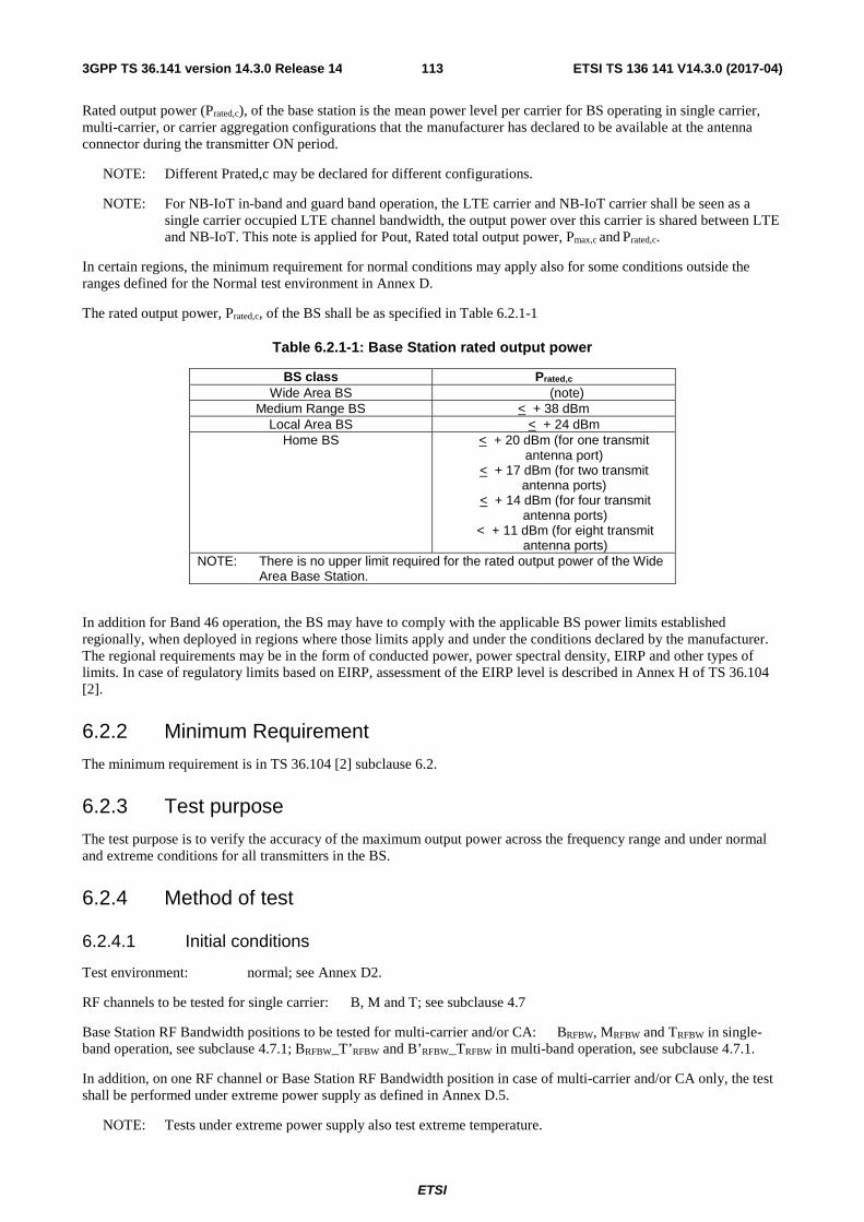
ETSI
ETSI TS 136 141 V14.3.0 (2017-04)1133GPP TS 36.141 version 14.3.0 Release 14
Rated output power (Prated,c), of the base station is the mean power level per carrier for BS operating in single carrier, multi-carrier, or carrier aggregation configurations that the manufacturer has declared to be available at the antenna connector during the transmitter ON period.
NOTE: Different Prated,c may be declared for different configurations.
NOTE: For NB-IoT in-band and guard band operation, the LTE carrier and NB-IoT carrier shall be seen as a single carrier occupied LTE channel bandwidth, the output power over this carrier is shared between LTE and NB-IoT. This note is applied for Pout, Rated total output power, Pmax,c and Prated,c.
In certain regions, the minimum requirement for normal conditions may apply also for some conditions outside the ranges defined for the Normal test environment in Annex D.
The rated output power, Prated,c, of the BS shall be as specified in Table 6.2.1-1
Table 6.2.1-1: Base Station rated output power
BS class Prated,c Wide Area BS (note)
Medium Range BS < + 38 dBm Local Area BS < + 24 dBm
Home BS < + 20 dBm (for one transmit antenna port)
< + 17 dBm (for two transmit antenna ports)
< + 14 dBm (for four transmit antenna ports)
< + 11 dBm (for eight transmit antenna ports)
NOTE: There is no upper limit required for the rated output power of the Wide Area Base Station.
In addition for Band 46 operation, the BS may have to comply with the applicable BS power limits established regionally, when deployed in regions where those limits apply and under the conditions declared by the manufacturer. The regional requirements may be in the form of conducted power, power spectral density, EIRP and other types of limits. In case of regulatory limits based on EIRP, assessment of the EIRP level is described in Annex H of TS 36.104 [2].
6.2.2 Minimum Requirement
The minimum requirement is in TS 36.104 [2] subclause 6.2.
6.2.3 Test purpose
The test purpose is to verify the accuracy of the maximum output power across the frequency range and under normal and extreme conditions for all transmitters in the BS.
6.2.4 Method of test
6.2.4.1 Initial conditions
Test environment: normal; see Annex D2.
RF channels to be tested for single carrier: B, M and T; see subclause 4.7
Base Station RF Bandwidth positions to be tested for multi-carrier and/or CA: BRFBW, MRFBW and TRFBW in single-band operation, see subclause 4.7.1; BRFBW_T’RFBW and B’RFBW_TRFBW in multi-band operation, see subclause 4.7.1.
In addition, on one RF channel or Base Station RF Bandwidth position in case of multi-carrier and/or CA only, the test shall be performed under extreme power supply as defined in Annex D.5.
NOTE: Tests under extreme power supply also test extreme temperature.

ETSI
ETSI TS 136 141 V14.3.0 (2017-04)1143GPP TS 36.141 version 14.3.0 Release 14
1) Connect the power measuring equipment to the base station antenna connector as shown in Annex I.1.1.
6.2.4.2 Procedure
1) For an E-UTRA BS declared to be capable of single carrier operation only, set the base station to transmit a signal according to E-TM1.1.
For an E-UTRA BS declared to be capable of multi-carrier and/or CA operation, set the base station to transmit according to E-TM1.1 on all carriers configured using in the applicable test configuration and corresponding power setting specified in sub-clause 4.10 and 4.11.
- For an E-UTRA BS declared to be capable of NB-IoT in-band operation, start transmission according to E-TM1.1 with the NB-IoT PRB constructed according to N-TM at manufacturer’s declared rated output power using the applicable test configuration and corresponding power setting specified in sub-clause 4.10 and 4.11.
- For an E-UTRA BS declared to be capable of NB-IoT guard-band operation, start transmission according to E-TM1.1 with the NB-IoT PRB constructed according to N-TM at manufacturer’s declared rated output power using the applicable test configuration and corresponding power setting specified in sub-clause 4.10 and 4.11..
- For a NB-IoT BS declared to be capable of single carrier operation, start transmission according to N-TM at manufacturer’s declared rated output power.
- For a NB-IoT BS declared to be capable of multi-carrier operation, set the base station to transmit according to N-TM on all carriers configured using in the applicable test configuration and corresponding power setting specified in sub-clause 4.10 and 4.11.
- For an E-UTRA and NB-IoT standalone BS declared to be capable of multi-carrier operation, start transmission according to E-TM1.1 on all E-UTRA carriers and N-TM on all NB-IoT carriers configured using in the applicable test configuration and corresponding power setting specified in sub-clause 4.10 and 4.11.
2) Measure the mean power for each carrier at the antenna connector.
In addition, for a multi-band capable BS, the following step shall apply:
3) For multi-band capable BS and single band tests, repeat the steps above per involved band where single band test configurations and test models shall apply with no carrier activated in the other band. For multi-band capable BS with separate antenna connector, the antenna connector not being under test in case of single-band or multi-band test shall be terminated.
6.2.5 Test Requirements
In normal conditions, for E-UTRA the measurement result in step 2 of 6.2.4.2 shall remain:
within +2.7 dB and –2.7 dB of the manufacturer's rated output power, Prated,c, for carrier frequency f ≤ 3.0GHz.
within +3.0 dB and –3.0 dB of the manufacturer's rated output power, Prated,c, for carrier frequency 3.0GHz < f ≤ 4.2GHz.
In extreme conditions, for E-UTRA measurement result in step 2 of 6.2.4.2 shall remain:
within +3.2 dB and –3.2 dB of the manufacturer's rated output power, Prated,c, for carrier frequency f ≤ 3.0GHz.
within +3.5 dB and –3.5 dB of the manufacturer's rated output power, Prated,c, for carrier frequency 3.0GHz < f ≤ 4.2GHz.
In normal conditions, for standalone NB-IoT the measurement result in step 2 of 6.2.4.2 shall remain:
within +3.0 dB and –3.0 dB of the manufacturer's rated output power, Prated,c
In extreme conditions, for standalone NB-IoT measurement result in step 2 of 6.2.4.2 shall remain:
within +3.5 dB and –3.5 dB of the manufacturer's rated output power, Prated,c

ETSI
ETSI TS 136 141 V14.3.0 (2017-04)1153GPP TS 36.141 version 14.3.0 Release 14
NOTE: If the above Test Requirement differs from the Minimum Requirement then the Test Tolerance applied for this test is non-zero. The Test Tolerance for this test and the explanation of how the Minimum Requirement has been relaxed by the Test Tolerance are given in Annex G.
6.2.6 Home BS output power for adjacent UTRA channel protection
6.2.6.1 Definition and applicability
The Home BS shall be capable of adjusting the transmitter output power to minimize the interference level on the adjacent channels licensed to other operators in the same geographical area while optimize the Home BS coverage. These requirements are only applicable to Home BS. The requirements in this clause are applicable for AWGN radio propagation conditions.
The output power, Pout, of the Home BS shall be as specified in Table 6.2.6-1 under the following input conditions:
- CPICH Êc, measured in dBm, is the code power of the Primary CPICH on one of the adjacent channels present at the Home BS antenna connector for the CPICH received on the adjacent channels. If Tx diversity is applied on the Primary CPICH, CPICH Êc shall be the sum in [W] of the code powers of the Primary CPICH transmitted from each antenna.
- Ioh, measured in dBm, is the total received power density, including signals and interference but excluding the own Home BS signal, present at the Home BS antenna connector on the Home BS operating channel.
In case that both adjacent channels are licensed to other operators, the most stringent requirement shall apply for Pout. In the case when one of the adjacent channels is licensed to an E-UTRA operator while the other adjacent channel is licensed to a UTRA operator, the more stringent requirement of this subclause and subclause 6.2.7 shall apply for Pout. In case the Home BS’s operating channel and both adjacent channels are licensed to the same operator, the requirements of this clause do not apply.
The input conditions defined for the requirements in this section are specified at the antenna connector of the Home BS. For Home BS receivers with diversity, the requirements apply to each antenna connector separately, with the other one(s) terminated or disabled. The requirements are otherwise unchanged. For Home BS(s) without measurement capability, a reference antenna with a gain of 0 dBi is assumed for converting these power levels into field strength requirements.
Table 6.2.6-1: Home BS output power for adjacent operator UTRA channel protection
Input Conditions Output power, Pout
Ioh > CPICH Êc + 43 dB And CPICH Êc ≥ -105dBm
≤ 10 dBm
Ioh ≤ CPICH Êc + 43 dB and CPICH Êc ≥ -105dBm
≤ max(8 dBm, min(20 dBm, CPICH Êc + 100 dB))
NOTE 1: The Home BS transmitter output power specified in Table 6.2.6-1 assumes a Home BS reference antenna gain of 0 dBi, an target outage zone of 47dB around the Home BS for an UE on the adjacent channel, with an allowance of 2 dB for measurement errors, an ACIR of 33 dB, an adjacent channel UE CPICH Ec/Io target of -18 dB and the same CPICH Êc value at the adjacent channel UE as for the Home BS.
NOTE 2: For CPICH Êc < -105 dBm, the requirements in subclause 6.2 apply.
NOTE 3: The output power Pout is the sum transmit power across all the antenna connectors of the Home BS, with each transmit power measured at the respective antenna connectors.
6.2.6.2 Minimum Requirement
The minimum requirement is in TS 36.104 [2] subclause 6.2.3.

ETSI
ETSI TS 136 141 V14.3.0 (2017-04)1163GPP TS 36.141 version 14.3.0 Release 14
6.2.6.3 Test purpose
The test purpose is to verify the capability of the Home BS to adjust the transmitter output power according to the input conditions, as specified in Table 6.2.6-1, across the frequency range and under normal and extreme conditions for all transmitters in the BS.
6.2.6.4 Method of test
6.2.6.4.1 Initial conditions
Test environment: normal; see Annex D2.
RF channels to be tested for single carrier: M; see subclause 4.7.
In addition, on one UARFCN only, the test shall be performed under extreme power supply as defined in Annex D.5.
NOTE: Tests under extreme power supply also test extreme temperature.
Signal generators delivering co-channel and adjacent channel interferers are switched off.
1) Set-up the equipment as shown as shown in Annex I.1.4.
2) The Home BS is configured such that the adjacent channel is known to belong to another operator.
6.2.6.4.2 Procedure
1) Connect the combined downlink interfering signals (referred to as point D in Figure I.1-4) to the dedicated measurement port (referred to as point 1 in Figure I.1-4) if available, otherwise connect to point 2.
2) Configure the signal generator for co-channel interference to transmit AWGN over a bandwidth according to BWConfig centred on RF channel M.
3) Configure the signal generator for adjacent channel DL signal to transmit test model 1 in subclause 6.1.1.1 in [17] at the centre frequency equal to RF channel M + BWChannel /2 + 2.5 MHz.
4) Switch on signal generators delivering co-channel and adjacent channel interferers, and adjust the ATT1 and ATT2 such that CPICH Êc = -80 dBm and Ioh = -50 dBm.
5) Trigger the Home BS power adjustment mechanism.
6) Configure the Home BS to transmit a signal according to E-TM1.1.
NOTE: The signal shall be transmitted with the maximum allowed output power.
7) Measure Home BS output power, Pout, and check it is below the required value according to the CPICH Êc and Ioh values determined in step 4.
8) Repeat steps 3) to 7) with the frequency in step 3 set to RF channel M - BWChannel /2 - 2.5 MHz.
9) Repeat steps 3) to 8) with different settings for ATT1 and ATT2 to arrive the CPICH Êc and Ioh pairs as specified in Table 6.2.6-2.
Table 6.2.6-2: CPICH Êc and Ioh pairs
Test Case CPICH Êc (dBm) Ioh (dBm) 2 -90 -60 3 -100 -70 4 -100 -50
6.2.6.5 Test Requirements
In normal operating conditions, the output power, Pout, of the Home BS shall be equal to or less than:

ETSI
ETSI TS 136 141 V14.3.0 (2017-04)1173GPP TS 36.141 version 14.3.0 Release 14
the value specified in Table 6.2.6-1 plus 2.7 dB for carrier frequency f ≤ 3.0GHz.
the value specified in Table 6.2.6-1 plus 3.0 dB for carrier frequency 3.0GHz < f ≤ 4.2GHz.
In extreme operating conditions, the output power, Pout, of the Home BS shall be equal to or less than:
the value specified in Table 6.2.6-1 plus 3.2 dB for carrier frequency f ≤ 3.0GHz.
the value specified in Table 6.2.6-1 plus 3.5 dB for carrier frequency 3.0GHz < f ≤ 4.2GHz.
NOTE: If the above Test Requirement differs from the Minimum Requirement then the Test Tolerance applied for this test is non-zero. The Test Tolerance for this test and the explanation of how the Minimum Requirement has been relaxed by the Test Tolerance are given in Annex G.
6.2.7 Home BS output power for adjacent E-UTRA channel protection
6.2.7.1 Definition and applicability
The Home BS shall be capable of adjusting the transmitter output power to minimize the interference level on the adjacent channels licensed to other operators in the same geographical area while optimize the Home BS coverage. These requirements are only applicable to Home BS. The requirements in this clause are applicable for AWGN radio propagation conditions.
The output power, Pout, of the Home BS shall be as specified in Table 6.2.7-1 under the following input conditions:
- CRS Ês, measured in dBm, is the Reference Signal Received Power per resource element on one of the adjacent channels present at the Home BS antenna connector for the Reference Signal received on the adjacent channels. For CRS Ês determination, the cell-specific reference signal R0 according TS 36.211 [12] shall be used. If the Home BS can reliably detect that multiple TX antennas are used for transmission on the adjacent channel, it may use the average in [W] of the CRS Êc on all detected antennas.
- Ioh, measured in dBm, is the total received power density, including signals and interference but excluding the own Home BS signal, present at the Home BS antenna connector on the Home BS operating channel.
In case that both adjacent channels are licensed to other operators, the most stringent requirement shall apply for Pout. In the case when one of the adjacent channels is licensed to an E-UTRA operator while the other adjacent channel is licensed to a UTRA operator, the more stringent requirement of this subclause and subclause 6.2.6 shall apply for Pout. In case the Home BS’s operating channel and both adjacent channels are licensed to the same operator, the requirements of this clause do not apply.
The input conditions defined for the requirements in this section are specified at the antenna connector of the Home BS. For Home BS receivers with diversity, the requirements apply to each antenna connector separately, with the other one(s) terminated or disabled. The requirements are otherwise unchanged. For Home BS(s) without measurement capability, a reference antenna with a gain of 0 dBi is assumed for converting these power levels into field strength requirements.
Table 6.2.7-1: Home BS output power for adjacent operator E-UTRA channel protection
Input Conditions Output power, Pout
Ioh > CRS Ês +
+ 30 dB
and CRS Ês ≥ -127dBm
≤ 10 dBm
Ioh ≤ CRS Ês +
+ 30 dB
and CRS Ês ≥ -127dBm
≤ max(8 dBm, min(20 dBm, CRS Ês +
+ 85 dB))
( )RBsc
DLRB NN ⋅⋅ 10log10
( )RBsc
DLRB NN ⋅⋅ 10log10 ( )RB
scDLRB NN ⋅⋅ 10log10

ETSI
ETSI TS 136 141 V14.3.0 (2017-04)1183GPP TS 36.141 version 14.3.0 Release 14
NOTE 1: The Home BS transmitter output power specified in Table 6.2.7-1 assumes a Home BS reference antenna gain of 0 dBi, an target outage zone of 47dB around the Home BS for an UE on the adjacent channel, with an allowance of 2 dB for measurement errors, an ACIR of 30 dB, an adjacent channel UE Ês/Iot target of -6 dB and the same CRS Ês value at the adjacent channel UE as for the Home BS.
NOTE 2: For CRS Ês < -127 dBm, the requirements in subclause 6.2 apply.
NOTE 3: The output power Pout is the sum transmit power across all the antenna connectors of the Home BS, with each transmit power measured at the respective antenna connectors.
NOTE 4: DLRBN is the number of downlink resource blocks in the own Home BS channel.
NOTE 5: RBscN is the number of subcarriers in a resource block, 12=RB
scN .
6.2.7.2 Minimum Requirement
The minimum requirement is in TS 36.104 [2] subclause 6.2.4.
6.2.7.3 Test purpose
The test purpose is to verify the capability of the Home BS to adjust the transmitter output power according to the input conditions, as specified in Table 6.2.7-1, across the frequency range and under normal and extreme conditions for all transmitters in the BS.
6.2.7.4 Method of test
6.2.7.4.1 Initial conditions
Test environment: normal; see Annex D2.
RF channels to be tested for single carrier: M; see subclause 4.7.
In addition, on one EARFCN only, the test shall be performed under extreme power supply as defined in Annex D.5.
NOTE: Tests under extreme power supply also test extreme temperature.
Signal generators delivering co-channel and adjacent channel interferers are switched off.
1) Set-up the equipment as shown as shown in Annex I.1.4.
2) The Home BS is configured such that the adjacent channel is known to belong to another operator.
6.2.7.4.2 Procedure
1) Connect the combined downlink interfering signals (referred to as point D in Figure I.1-4) to the dedicated measurement port (referred to as point 1 in Figure I.1-4) if available, otherwise connect to point 2.
2) Configure the signal generator for co-channel interference to transmit AWGN over a bandwidth according to BWConfig centred on RF channel M.
3) Configure the signal generator for adjacent channel DL signal to transmit a signal according to E-TM1.1 at the centre frequency equal to RF channel M + BWChannel MHz.
4) Switch on signal generators delivering co-channel and adjacent channel interferers, and adjust the ATT1 and
ATT2 such that CRS Ês = -65 - dBm and Ioh = -50 dBm.
5) Trigger the Home BS power adjustment mechanism.
6) Configure the Home BS to transmit a signal according to E-TM1.1.
NOTE: The signal is transmitted with the maximum allowed output power.
( )RBsc
DLRB NN ⋅⋅ 10log10

ETSI
ETSI TS 136 141 V14.3.0 (2017-04)1193GPP TS 36.141 version 14.3.0 Release 14
7) Measure Home BS output power, Pout, and check it is below the required value according to the CRS Ês and Ioh values determined in step 4.
8) Repeat steps 3) to 7) with the frequency in step 3 set to RF channel M - BWChannel MHz.
9) Repeat steps 3) to 8) with different settings for ATT1 and ATT2 to arrive the CRS Ês and Ioh pairs as specified in Table 6.2.7-2.
Table 6.2.7-2: CRS Ês and Ioh pairs
Test Case CRS Ês (dBm) Ioh (dBm)
2 -75 - -60
3 -90 - -70
4 -90 - -50
6.2.7.5 Test Requirements
In normal operating conditions, the output power, Pout, of the Home BS shall be equal to or less than:
- the value specified in Table 6.2.7-1 plus 2.7 dB for carrier frequency f ≤ 3.0GHz.
- the value specified in Table 6.2.6-1 plus 3.0 dB for carrier frequency 3.0GHz < f ≤ 4.2GHz.
In extreme operating conditions, the output power, Pout, of the Home BS shall be equal to or less than:
- the value specified in Table 6.2.7-1 plus 3.2 dB for carrier frequency f ≤ 3.0GHz.
- the value specified in Table 6.2.6-1 plus 3.5 dB for carrier frequency 3.0GHz < f ≤ 4.2GHz.
NOTE: If the above Test Requirement differs from the Minimum Requirement then the Test Tolerance applied for this test is non-zero. The Test Tolerance for this test and the explanation of how the Minimum Requirement has been relaxed by the Test Tolerance are given in Annex G.
6.2.8 Home BS output power for co-channel E-UTRA protection
6.2.8.1 Definition and applicability
To minimize the co-channel DL interference to non-CSG macro UEs operating in close proximity while optimizing the CSG Home BS coverage, Home BS may adjust its output power according to the requirements set out in this clause. These requirements are only applicable to Home BS. The requirements in this clause are applicable for AWGN radio propagation conditions.
For Home BS that supports the requirements in this clause, the output power, Pout, of the Home BS shall be as specified in Table 6.2.8-1 under the following input conditions:
- CRS Ês, measured in dBm, is the Reference Signal Received Power per resource element present at the Home BS antenna connector received from the co-channel Wide Area BS. For CRS Ês determination, the cell-specific reference signal R0 according TS 36.211 [12] shall be used. If the Home BS can reliably detect that multiple TX antenna ports are used for transmission by the co-channel Wide Area Base Station, it may use the average in [W] of the CRS Ês on all detected TX antenna ports, including R0.
- Ioh, measured in dBm, is the total received DL power, including all interference but excluding the own Home BS signal, present at the Home BS antenna connector on the Home BS operating channel.
- Iob, measured in dBm, is the uplink received interference power, including thermal noise, within one physical
resource block’s bandwidth of RBscN resource elements as defined in TS 36.214, present at the Home BS antenna
connector on the Home BS operating channel.
( )RBsc
DLRB NN ⋅⋅ 10log10
( )RBsc
DLRB NN ⋅⋅ 10log10
( )RBsc
DLRB NN ⋅⋅ 10log10

ETSI
ETSI TS 136 141 V14.3.0 (2017-04)1203GPP TS 36.141 version 14.3.0 Release 14
The input conditions defined for the requirements in this section are specified at the antenna connector of the Home BS. For Home BS receivers with diversity, the requirements apply to each antenna connector separately, with the other one(s) terminated or disabled. The requirements are otherwise unchanged. For Home BS(s) without measurement capability, a reference antenna with a gain of 0 dBi is assumed for converting these power levels into field strength requirements.
Table 6.2.8-1: Home BS output power for co-channel E-UTRA channel protection
Input Conditions Output power, Pout
Ioh (DL) > CRS Ês + 10log10( DLRBN RB
scN ) + 30 dB
and Option 1: CRS Ês ≥ -127 dBm or Option 2: CRS Ês ≥ -127 dBm and Iob > -103 dBm
≤ 10 dBm
Ioh (DL) ≤ CRS Ês + 10log10( DLRBN RB
scN ) + 30 dB
and Option 1: CRS Ês ≥ -127 dBm or Option 2. CRS Ês ≥ -127 dBm and Iob > -103 dBm
≤ max (Pmin, min (Pmax,c, CRS Ês +
10log10( DLRBN RB
scN ) + X ))
30 dB ≤ X ≤ 70 dB Pmin = - 10 dBm
Note 1: Only the option supported by the Home BS shall be tested.
Note 2: For CRS Ês < -127dBm, or Iob ≤ -103 dBm when Option 2 is supported, the requirements in sub-clauses 6.2.1 and 6.2.2 apply.
Note 3: The output power Pout is the sum of transmits power across all the antennas of the Home BS, with each transmit power measured at the respective antenna connectors.
Note 4: DLRBN is the number of downlink resource blocks in the own Home BS channel.
Note 5: RBscN is the number of subcarriers in a resource block, 12=RB
scN .
Note 6: X is a network configurable parameter.
Note 7: Pmin can be lower dependent on the Home BS total dynamic range.
Note8: Other input conditions and output power to be applied for network scenarios other than co-channel E-UTRA macro channel protection shall not be precluded.
6.2.8.2 Minimum Requirement
The minimum requirement is in TS 36.104 [2] subclause 6.2.5.
6.2.8.3 Test purpose
The test purpose is to verify the capability of the Home BS to adjust the transmitter output power according to the input conditions, as specified in Table 6.2.8-1, across the frequency range and under normal and extreme conditions for all transmitters in the BS. For Home BS that supports the requirements in this clause, only the option in Table 6.2.8-1 supported by the Home BS shall be tested.
6.2.8.4 Method of test
6.2.8.4.1 Initial conditions
Test environment: normal; see Annex D2.

ETSI
ETSI TS 136 141 V14.3.0 (2017-04)1213GPP TS 36.141 version 14.3.0 Release 14
RF channels to be tested for single carrier: M; see subclause 4.7.
In addition, on one EARFCN only, the test shall be performed under extreme power supply as defined in Annex D.5.
NOTE: Tests under extreme power supply also test extreme temperature.
Signal generator delivering co-channel interferers is switched off.
1) Set-up the equipment as shown in Annex I.1.5, base on the option supported by Home BS.
2) The co-channel interference should be configured containing at least signals from a neighbouring Marco BS. For option 2 of Table 6.2.8-1, additional signal generator needed to deliver the MUE UL signal.
6.2.8.4.2 Procedure
1) Connect the downlink co-channel interfering signals (referred to as point D in Figure I.1-5) to the dedicated measurement port (referred to as point 1 in Figure I.1-5) if available, otherwise connect to point 2. Specifically for option 2 of Table 6.2.8-1, connect the UL interference to point 2 for UL receiving on the figure of I.1.5-b.
2) Configure the signal generator for co-channel interference to transmit AWGN over a bandwidth according to BWConfig centred on RF channel M.
3) Configure the X as 30 dB. Switch on signal generators delivering interferers, and adjust the ATT such that CRS
Ês = -10 -10log10( DLRBN RB
scN ) dBm and Ioh = -50 dBm.
4) Trigger the Home BS power adjustment mechanism.
5) Configure the Home BS to transmit a signal according to E-TM1.1.
NOTE: The signal is transmitted with the maximum allowed output power.
6) Measure Home BS output power, Pout, and check it is below the required value according to the CRS Ês and Ioh values determined in step 4. The value of Pmin for testing is -10dBm.
7) Repeat steps 4) to 6) with different settings for ATT to arrive the input parameter pairs as specified in Table 6.2.8-2 or 6.2.8-3, basing the option of Table 6.2.8-1supported by the Home BS.
Table 6.2.8-2: CRS Ês and Ioh pairs for option 1
Test Case CRS Ês (dBm) Ioh (dBm)
1 -20- 10log10( DLRBN RB
scN ) -60
2 Pmin-30 -10log10( DLRBN RB
scN ) -70
3 -90 - 10log10( DLRBN RB
scN ) -50
Table 6.2.8-3: CRS Ês, Ioh and Iob pairs for option 2
Test Case CRS Ês (dBm) Ioh (dBm) Iob (dBm)
1 -20 - 10log10( DLRBN RB
scN ) -60 -98
2 Pmin-30 -10log10( DLRBN RB
scN ) -70 -98
3 -90 - 10log10( DLRBN RB
scN ) -50 -98
6.2.8.5 Test Requirements
In normal operating conditions, the output power, Pout, of the Home BS shall be equal to or less than the value specified in Table 6.2.8-1 plus 2.7 dB.

ETSI
ETSI TS 136 141 V14.3.0 (2017-04)1223GPP TS 36.141 version 14.3.0 Release 14
In extreme operating conditions, the output power, Pout, of the Home BS shall be equal to or less than the value specified in Table 6.2.8-1 plus 3.2 dB.
NOTE: If the above Test Requirement differs from the Minimum Requirement then the Test Tolerance applied for this test is non-zero. The Test Tolerance for this test and the explanation of how the Minimum Requirement has been relaxed by the Test Tolerance are given in Annex G.
6.3 Output power dynamics The requirements in subclause 6.3 apply during the transmitter ON period.
6.3.1 RE Power control dynamic range
6.3.1.1 Definition and applicability
The RE power control dynamic range is the difference between the power of an RE and the average RE power for a BS at maximum output power for a specified reference condition. Unwanted emissions (as specified in subclause 6.6) and Transmit modulation quality (as specified in subclause 6.5) shall be maintained within the whole power control dynamic range.
6.3.1.2 Minimum Requirement
The minimum requirement is in TS 36.104 [2] subclause 6.3.1.1.
6.3.1.3 Method of test
No specific test or test requirements are defined for RE Power control dynamic range. The Error Vector Magnitude test, as described in subclause 6.5.2 provides sufficient test coverage for this requirement.
6.3.2 Total power dynamic range
6.3.2.1 Definition and applicability
The total power dynamic range is the difference between the maximum and the minimum transmit power of an OFDM symbol for a specified reference condition.
NOTE: The upper limit of the dynamic range is the OFDM symbol power for a BS at maximum output power. The lower limit of the dynamic range is the OFDM symbol power for a BS when one resource block is transmitted. The OFDM symbol shall carry PDSCH and not contain RS, PBCH or synchronisation signals.
6.3.2.2 Minimum Requirement
The minimum requirement is in TS 36.104 [2] subclause 6.3.2.1.
6.3.2.3 Test purpose
The test purpose is to verify that the total power dynamic range is met as specified by the minimum requirement.
6.3.2.4 Method of test
6.3.2.4.1 Initial conditions
Test environment: normal; see Annex D.2.
RF channels to be tested for single carrier: B, M and T; see subclause 4.7.
Connect the signal analyzer to the base station antenna connector as shown in Annex I.1.1.

ETSI
ETSI TS 136 141 V14.3.0 (2017-04)1233GPP TS 36.141 version 14.3.0 Release 14
6.3.2.4.2 Procedure
1) Set-up BS transmission at maximum total power as specified by the supplier. Channel set-up shall be according to E-TM 3.1.
2) Measure the average OFDM symbol power as defined in Annex F.
3) Set the BS to transmit a signal according to E-TM 2.
4) Measure the average OFDM symbol power as defined in Annex F. The measured OFDM symbols shall not contain RS, PBCH or synchronisation signals.
5) Repeat step 1 and 2 for E-TM3.1a and step 3 and 4 for E-TM2a for 256QAM, if supported by the BS.
In addition, for a multi-band capable BS, the following step shall apply:
6) For multi-band capable BS and single band tests, repeat the steps above per involved band where single carrier test models shall apply with no carrier activated in the other band. For multi-band capable BS with separate antenna connector, the antenna connector not being under test shall be terminated.
6.3.2.5 Test Requirement
The downlink (DL) total power dynamic range for each E-UTRA carrier shall be larger than or equal to the level in Table 6.3.2-1.
Table 6.3.2-1 E-UTRA BS total power dynamic range, paired spectrum
E-UTRA channel bandwidth (MHz)
Total power dynamic range (dB)
1.4 7.3 3 11.3 5 13.5
10 16.5 15 18.3 20 19.6
NOTE 1: If the above Test Requirement differs from the Minimum Requirement then the Test Tolerance applied for this test is non-zero. The Test Tolerance for this test is defined in Annex G. The explanation of how the Minimum Requirement has been relaxed by the Test Tolerance is given in Annex G.
NOTE2: Additional test requirements for the Error Vector Magnitude (EVM) at the lower limit of the dynamic range are defined in subclause 6.5.2.
6.3.3 NB-IoT RB power dynamic range for in-band or guard band operation
6.3.3.1 Definition and applicability
The NB-IoT RB power dynamic range (or NB-IoT power boosting) is the difference between the power of NB-IoT carrier (which occupies a PRB of LTE carrier in-band or 180kHz in guard band) and the average power over all carriers (both LTE and NB-IoT).
6.3.2.2 Minimum Requirement
The minimum requirement is in TS 36.104 [2] subclause 6.3.3.1.
6.3.3.3 Test purpose
The test purpose is to verify that the NB-IoT RB power dynamic range for in-band or guard band operation is met as specified by the minimum requirement.

ETSI
ETSI TS 136 141 V14.3.0 (2017-04)1243GPP TS 36.141 version 14.3.0 Release 14
6.3.3.4 Method of test
Requirement is tested together with unwanted emissions test, as described in subclause 6.6.3.
6.3.3.5 Test Requirement
NB-IoT power dynamic range shall be larger than or equal to +5.6 dB, except for guard band operation with E-UTRA 5 MHz channel bandwidth signal where BS manufacturer shall declare the NB-IoT dynamic range power it could support (in this version of the specification).
The +5.6 dB power dynamic range is only required for one NB-IoT PRB for both in-band and guard band operation modes.
For guard band operation, this NB-IoT PRB should be placed adjacent to the LTE PRB edge as close as possible (i.e., away from edge of channel bandwidth).
6.4 Transmit ON/OFF power The requirements in section 6.4 are only applied for E-UTRA TDD BS.
6.4.1 Transmitter OFF power
6.4.1.1 Definition and applicability
Transmitter OFF power is defined as the mean power measured over 70 us filtered with a square filter of bandwidth equal to the transmission bandwidth configuration of the BS (BWConfig) centred on the assigned channel frequency during the transmitter OFF period.
For BS supporting intra-band contiguous CA, the transmitter OFF power is defined as the mean power measured over 70 us filtered with a square filter of bandwidth equal to the Aggregated Channel Bandwidth BWChannel_CA centred on (Fedge_high+Fedge_low)/2 during the transmitter OFF period.
6.4.1.2 Minimum Requirement
The minimum requirement is in TS 36.104 [2] subclause 6.4.1.1.
6.4.1.3 Test purpose
The purpose of this test is to verify the E-UTRA BS transmitter OFF power is within the limit of the minimum requirement.
6.4.1.4 Method of test
Requirement is tested together with transmitter transient period, as described in subclause 6.4.2.4.
6.4.1.4.1 Void
6.4.1.4.2 Void
6.4.1.5 Test requirement
The conformance testing of transmit OFF power is included in the conformance testing of transmitter transient period; therefore, see subclause 6.4.2.5 for test requirements.

ETSI
ETSI TS 136 141 V14.3.0 (2017-04)1253GPP TS 36.141 version 14.3.0 Release 14
6.4.2 Transmitter transient period
6.4.2.1 Definition and applicability
The transmitter transient period is the time period during which the transmitter is changing from the OFF period to the ON period or vice versa. The transmitter transient period is illustrated in Figure 6.4.2.1-1.
Transmitter Output Power
Time
Transmitter ON period (DL Subframe and DwPTS)
Transmitter OFF period
Transmitter OFF period
Transmitter transient period
OFF power level
ON power level (Informative)
Figure 6.4.2.1-1 Illustration of the relations of transmitter ON period, transmitter OFF period and transmitter transient period.
6.4.2.2 Minimum Requirement
The minimum requirement is in TS 36.104 [2] subclause 6.4.2.1.
6.4.2.3 Test purpose
The purpose of this test is to verify the E-UTRA BS transmitter transient periods are within the limit of the minimum requirement.
6.4.2.4 Method of test
6.4.2.4.1 Initial conditions
Test environment: normal; see Annex D.2.
RF channels to be tested for single carrier: M; see subclause 4.7.
Base Station RF Bandwidth positions to be tested for multi-carrier and/or CA: MRFBW in single-band operation, see subclause 4.7.1; BRFBW_T’RFBW and B’RFBW_TRFBW in multi-band operation, see subclause 4.7.1.
Connect the signal analyzer to the BS antenna connector as shown in Annex I.1.1.
As a general rule, the resolution bandwidth of the measuring equipment should be equal to the measurement bandwidth. However, to improve measurement accuracy, sensitivity, efficiency and avoiding e.g. carrier leakage, the resolution bandwidth may be smaller than the measurement bandwidth. When the resolution bandwidth is smaller than the measurement bandwidth, the result should be integrated over the measurement bandwidth in order to obtain the equivalent noise bandwidth of the measurement bandwidth.

ETSI
ETSI TS 136 141 V14.3.0 (2017-04)1263GPP TS 36.141 version 14.3.0 Release 14
6.4.2.4.2 Procedure
1) For a BS declared to be capable of single carrier operation only, set the BS to transmit a signal according to E-TM1.1 at manufacturer’s declared rated output power.
For a BS declared to be capable of multi-carrier and/or CA operation, set the BS to transmit according to E-TM1.1 on all carriers configured using the applicable test configuration and corresponding power setting specified in sub-clause 4.10 and 4.11.
2) Measure the mean power spectral density over 70μs filtered with a square filter of bandwidth equal to the Transmission bandwidth configuration BWconfig centred on the assigned channel frequency. 70μs average window centre is set from 35μs after end of one transmitter ON period + 17μs to 35μs before start of next transmitter ON period – 17μs.
3) For BS supporting contiguous CA, measure the mean power spectral density over 70μs filtered with a square filter of bandwidth equal to the Aggregated Channel Bandwidth BWChannel_CA centred on (Fedge_high+Fedge_low)/2. 70μs average window centre is set from 35μs after end of one transmitter ON period + 17μs to 35μs before start of next transmitter ON period – 17μs.
For a multi-band capable BS,
with separate antenna connector, the antenna connector not being under test shall be terminated.
6.4.2.5 Test requirement
The measured mean power spectral density shall be less than -83dBm/MHz for carrier frequency f ≤ 3.0GHz.
The measured mean power spectral density shall be less than -82.5dBm/MHz for carrier frequency 3.0GHz < f ≤ 4.2GHz.
For BS capable of multi-band operation, the requirement is only applicable during the transmitter OFF period in all supported operating bands.
NOTE: If the above Test Requirement differs from the Minimum Requirement then the Test Tolerance applied for this test is non-zero. The Test Tolerance for this test and the explanation of how the Minimum Requirement has been relaxed by the Test Tolerance are given in Annex G.
6.5 Transmitted signal quality The requirements in subclause 6.5 apply to the transmitter ON period.
6.5.1 Frequency error
6.5.1.1 Definition and applicability
Frequency error is the measure of the difference between the actual BS transmit frequency and the assigned frequency. The same source shall be used for RF frequency and data clock generation.
It is not possible to verify by testing that the data clock is derived from the same frequency source as used for RF generation. This may be confirmed by the manufacturer’s declaration.
6.5.1.2 Minimum Requirement
The minimum requirement is in TS 36.104 [2] subclause 6.5.1.
6.5.1.3 Test purpose
To verify that the Frequency Error is within the limit of the minimum requirement.

ETSI
ETSI TS 136 141 V14.3.0 (2017-04)1273GPP TS 36.141 version 14.3.0 Release 14
6.5.1.4 Method of test
Requirement is tested together with Error Vector Magnitude test, as described in subclause 6.5.2.
6.5.1.5 Test requirement
For E-UTRA, the modulated carrier frequency of each E-UTRA carrier configured by the BS shall be accurate to within the accuracy range given in Table 6.5.1-1 observed over a period of one subframe (1ms).
For NB-IoT, the modulated carrier frequency of each NB-IoT carrier configured by the BS shall be accurate to within the accuracy range given in Table 6.5.1-1 observed over a period of one subframe (1ms).
Table 6.5.1-1: Frequency error test requirement
BS class Accuracy Wide Area BS ± (0.05 ppm + 12 Hz)
Medium Range BS ± (0.1 ppm + 12 Hz) Local Area BS ± (0.1 ppm + 12 Hz)
Home BS ± (0.25 ppm + 12 Hz)
NOTE: If the above Test Requirement differs from the Minimum Requirement then the Test Tolerance applied for this test is non-zero. The Test Tolerance for this test and the explanation of how the Minimum Requirement has been relaxed by the Test Tolerance are given in Annex G.
6.5.2 Error Vector Magnitude
6.5.2.1 Definition and applicability
The Error Vector Magnitude is a measure of the difference between the ideal symbols and the measured symbols after the equalization. This difference is called the error vector. The equaliser parameters are estimated as defined in Annex F. The EVM result is defined as the square root of the ratio of the mean error vector power to the mean reference power expressed in percent.
6.5.2.2 Minimum Requirement
The minimum requirement is in TS 36.104 [2] subclause 6.5.2.
6.5.2.3 Test purpose
The test purpose is to verify that the Error Vector Magnitude is within the limit specified by the minimum requirement.
6.5.2.4 Method of test
6.5.2.4.1 Initial conditions
Test environment: normal; see Annex D.2.
RF channels to be tested for single carrier: B, M and T; see subclause 4.7.
Base Station RF Bandwidth positions to be tested for multi-carrier and/or CA: BRFBW, MRFBW and TRFBW in single-band operation, see subclause 4.7.1; BRFBW_T’RFBW and B’RFBW_TRFBW in multi-band operation, see subclause 4.7.1.
Connect the signal analyzer to the base station antenna connector as shown in Annex I.1.1.
6.5.2.4.2 Procedure
1) For a BS declared to be capable of single carrier operation only, set the BS to transmit a signal according to E-TM 3.1 at manufacturer’s declared rated output power.

ETSI
ETSI TS 136 141 V14.3.0 (2017-04)1283GPP TS 36.141 version 14.3.0 Release 14
For a BS declared to be capable of multi-carrier and/or CA operation, set the BS to transmit according to E-TM 3.1 on all carriers configured using the applicable test configuration and corresponding power setting specified in sub-clause 4.10 and 4.11.
For a NB-IoT BS declared to be capable of single carrier operation, start transmission according to N-TM at manufacturer’s declared rated output power.
For a NB-IoT BS declared to be capable of multi-carrier operation, set the base station to transmit according to N-TM on all carriers configured using in the applicable test configuration and corresponding power setting specified in sub-clause 4.10 and 4.11.
For an E-UTRA and NB-IoT standalone BS declared to be capable of multi-carrier operation, start transmission according to E-TM 3.1 on all E-UTRA carriers and N-TM on all NB-IoT carriers configured using in the applicable test configuration and corresponding power setting specified in sub-clause 4.10 and 4.11.
2) Measure the EVM and frequency error as defined in Annex F.
3) For E-UTRA repeat steps 1 and 2 for E-TM 3.2, E-TM 3.3 and E-TM 2. Repeat steps 1 and 2 for E-TM3.1a and E-TM 2a for 256QAM, if supported by the BS. For E-TM2 and E-TM2a the OFDM symbol power shall be at the lower limit of the dynamic range according to the test procedure in subclause 6.3.2.4.2 and test requirements in subclause 6.3.2.5.
In addition, for a multi-band capable BS, the following step shall apply:
4) For multi-band capable BS and single band tests, repeat the steps above per involved band where single band test configurations and test models shall apply with no carrier activated in the other band. For multi-band capable BS with separate antenna connector, the antenna connector not being under test in case of single-band or multi-band test shall be terminated.
6.5.2.5 Test requirement
The EVM of each E-UTRA carrier for different modulation schemes on PDSCH shall be less than the limits in table 6.5.2.5-1:
Table 6.5.2.5-1 EVM requirements for E-UTRA carrier
Modulation scheme for PDSCH Required EVM [%] QPSK 18.5 %
16QAM 13.5 % 64QAM 9 %
256QAM 4.5%
The EVM of each NB-IoT carrier on NB-PDSCH shall be less than the limits in table 6.5.2.5-1a:
Table 6.5.2.5-1a EVM requirements for NB-IoT carrier
Modulation scheme for NB-PDSCH Required EVM [%] QPSK 18.5 %
The EVM requirement shall be applicable within a time period around the centre of the CP therefore the EVM requirement is tested against the maximum of the RMS average of 10 subframes at the two window W extremities.
Table 6.5.2.5-2 and Table 6.5.2.5-2a specify EVM window length (W) for normal CP, the cyclic prefix length cpN is
160 for symbols 0 and 144 for symbols 1-6.

ETSI
ETSI TS 136 141 V14.3.0 (2017-04)1293GPP TS 36.141 version 14.3.0 Release 14
Table 6.5.2.5-2 EVM window length for normal CP for E-UTRA
Channel Bandwidth
MHz FFT size
Cyclic prefix length for
symbols 0 in FFT samples
Cyclic prefix
length for symbols
1-6 in FFT samples
EVM window length W
Ratio of W to total CP
for symbols 1-6* [%]
1.4 128 10 9 5 55.6 3 256 20 18 12 66.7 5 512 40 36 32 88.9 10 1024 80 72 66 91.7 15 1536 120 108 102 94.4 20 2048 160 144 136 94.4
* Note: These percentages are informative and apply to symbols 1 through 6. Symbol 0 has a longer CP and therefore a lower percentage.
Table 6.5.2.5-2a EVM window length for normal CP for NB-IoT
FFT size
Cyclic prefix length for
symbols 0 in FFT samples
Cyclic prefix
length for symbols
1-6 in FFT samples
EVM window length W
Ratio of W to total CP
for symbols 1-61 [%]
128 10 9 3 33.3 Note 1: These percentages are informative and apply to symbols 1
through 6. Symbol 0 has a longer CP and therefore a lower percentage.
NOTE: If the above Test Requirement differs from the Minimum Requirement then the Test Tolerance applied for this test is non-zero. The Test Tolerance for this test is defined in Annex G. The explanation of how the Minimum Requirement has been relaxed by the Test Tolerance is given in Annex G.
6.5.3 Time alignment error
6.5.3.1 Definition and applicability
Frames of the LTE signals present at the BS transmitter antenna port(s) are not perfectly aligned in time. In relation to each other, the RF signals present at the BS transmitter antenna port(s) experience certain timing differences.
For a specific set of signals/transmitter configuration/transmission mode, time alignment error (TAE) is defined as the largest timing difference between any two signals. This test is only applicable for eNode B supporting TX diversity MIMO transmission, carrier aggregation and their combinations.
6.5.3.2 Minimum Requirement
The minimum requirement is in TS 36.104 [2] subclause 6.5.3.
6.5.3.3 Test Purpose
To verify that the timing alignment error in TX diversity, MIMO transmission, carrier aggregation and their combinations is within the limit specified by the minimum requirement.
6.5.3.4 Method of Test
6.5.3.4.1 Initial Conditions
Test environment: normal; see Annex D.2.

ETSI
ETSI TS 136 141 V14.3.0 (2017-04)1303GPP TS 36.141 version 14.3.0 Release 14
RF channels to be tested for single carrier: M; see subclause 4.7.
Base Station RF Bandwidth positions to be tested for multi-carrier and/or CA: MRFBW in single-band operation, see subclause 4.7.1; BRFBW_T’RFBW and B’RFBW_TRFBW in multi-band operation, see subclause 4.7.1.
1) Connect two base station RF antenna ports to the measurement equipment according to Annex I.1.3. If available terminate the other unused antenna ports.
6.5.3.4.2 Procedure
1) Set the base station to transmit E-TM1.1 or any DL signal using TX diversity, MIMO transmission or carrier aggregation.
NOTE: For TX diversity and MIMO transmission, different ports may be configured in E-TM (using p = 0 and 1).
For a BS declared to be capable of single carrier operation only, set the BS to transmit according to manufacturer’s declared rated output power.
If the BS supports intra band contiguous or non-contiguous Carrier Aggregation set the base station to transmit using the applicable test configuration and corresponding power setting specified in sub-clause 4.10 and 4.11.
If the BS supports inter band carrier aggregation set the base station to transmit, for each band, a single carrier or all carriers, using the applicable test configuration and corresponding power setting specified in sub clause 4.10 and 4.11.
For a NB-IoT BS declared to be capable of single carrier operation, start transmission according to N-TM at manufacturer’s declared rated output power.
For a NB-IoT BS declared to be capable of multi-carrier operation, set the base station to transmit according to N-TM on all carriers configured using in the applicable test configuration and corresponding power setting specified in sub-clause 4.10 and 4.11.
For an E-UTRA and NB-IoT standalone BS declared to be capable of multi-carrier operation, start transmission according to E-TM1.1 on all E-UTRA carriers and N-TM on all NB-IoT carriers configured using in the applicable test configuration and corresponding power setting specified in sub-clause 4.10 and 4.11.
2) Measure the time alignment error between the reference symbols on the carrier(s) from active antenna port(s).
3) Repeat the step 1 and 2 for any other possible configuration of transmit antennas.
In addition, for a multi-band capable BS, the following step shall apply:
4) For multi-band capable BS and single band tests, repeat the steps above per involved band where single band test configurations and test models shall apply with no carrier activated in the other band. For multi-band capable BS with separate antenna connector, the antenna connector not being under test in case of single-band or multi-band test shall be terminated.
6.5.3.5 Test Requirement
For E-UTRA:
- For MIMO or TX diversity transmissions, at each carrier frequency, TAE shall not exceed 90 ns.
- For intra-band carrier aggregation, with or without MIMO or TX diversity, TAE shall not exceed 155 ns.
- For intra-band non-contiguous carrier aggregation, with or without MIMO or TX diversity, TAE shall not exceed 285 ns.
- For inter-band carrier aggregation, with or without MIMO or TX diversity, TAE shall not exceed 285 ns.
For NB-IoT:
- For TX diversity transmissions, at each carrier frequency, TAE shall not exceed 90 ns.

ETSI
ETSI TS 136 141 V14.3.0 (2017-04)1313GPP TS 36.141 version 14.3.0 Release 14
NOTE: If the above Test Requirement differs from the Minimum Requirement then the Test Tolerance applied for this test is non-zero. The Test Tolerance for this test and the explanation of how the Minimum Requirement has been relaxed by the Test Tolerance are given in Annex G.
6.5.4 DL RS power
6.5.4.1 Definition and applicability
For E-UTRA, DL RS power is the resource element power of Downlink Reference Symbol.
The absolute DL RS power is indicated on the DL-SCH. The absolute accuracy is defined as the maximum deviation between the DL RS power indicated on the DL-SCH and the DL RS power of each E-UTRA carrier at the BS antenna connector.
For NB-IoT, DL NRS power is the resource element power of the Downlink Narrow-band Reference Signal.
The absolute DL NRS power is indicated on the DL-SCH. The absolute accuracy is defined as the maximum deviation between the DL NRS power indicated on the DL-SCH and the DL NRS power of each NB-IoT carrier at the BS antenna connector.
6.5.4.2 Minimum Requirement
The minimum requirement is in TS 36.104 [2] subclause 6.5.4.
6.5.4.3 Test purpose
The test purpose is to verify that the DL RS/NRS power is within the limit specified by the minimum requirement.
6.5.4.4 Method of test
6.5.4.4.1 Initial conditions
Test environment: normal; see Annex D.2.
RF channels to be tested for single carrier: B, M and T; see subclause 4.7.
Connect the signal analyzer to the base station antenna connector as shown in Annex I.1.1.
6.5.4.4.2 Procedure
For E-UTRA, set-up BS transmission at manufacturer’s declared rated output power. Channel set-up shall be according to E-TM 1.1.
For NB-IoT, Set-up BS transmission at manufacturer’s declared rated output power. Channel set-up shall be according to N-TM.
Measure the RS transmitted power according to annex F.
In addition, for a multi-band capable BS, the following step shall apply:
- For multi-band capable BS and single band tests, repeat the steps above per involved band where single carrier test models shall apply with no carrier activated in the other band. For multi-band capable BS with separate antenna connector, the antenna connector not being under test shall be terminated.
6.5.4.5 Test requirement
For E-UTRA, DL RS power of each E-UTRA carrier shall be:
within ± 2.9 dB of the DL RS power indicated on the DL-SCH for carrier frequency f ≤ 3.0GHz.
within ± 3.2 dB of the DL RS power indicated on the DL-SCH for carrier frequency 3.0GHz < f ≤ 4.2GHz.

ETSI
ETSI TS 136 141 V14.3.0 (2017-04)1323GPP TS 36.141 version 14.3.0 Release 14
For NB-IoT, DL NRS power of each NB-IoT carrier shall be:
within ± 2.9 dB of the DL NRS power indicated on the DL-SCH for carrier frequency f ≤ 3.0GHz.
NOTE 1: If the above Test Requirement differs from the Minimum Requirement then the Test Tolerance applied for this test is non-zero. The Test Tolerance for this test is defined in Annex G. The explanation of how the Minimum Requirement has been relaxed by the Test Tolerance is given in Annex G.
NOTE 2: PDSCH in E-TM1.1 is configured as "all 0" and DL RS power is not indicated on PDSCH during the measurement. The absolute DL RS power indicated on the DL-SCH can be calculated as Pmax,c – 10log10
(12* NRB) dBm, where NRB is the transmission bandwidth configuration of E-TM1.1.
6.6 Unwanted emissions Unwanted emissions consist of out-of-band emissions and spurious emissions [5]. Out of band emissions are unwanted emissions immediately outside the channel bandwidth resulting from the modulation process and non-linearity in the transmitter but excluding spurious emissions. Spurious emissions are emissions which are caused by unwanted transmitter effects such as harmonics emission, parasitic emission, intermodulation products and frequency conversion products, but exclude out of band emissions.
The out-of-band emissions requirement for the BS transmitter is specified both in terms of Adjacent Channel Leakage power Ratio (ACLR) and Operating band unwanted emissions. The Operating band unwanted emissions define all unwanted emissions in each supported downlink operating band plus the frequency ranges 10 MHz above and 10 MHz below each band. Unwanted emissions outside of this frequency range are limited by a spurious emissions requirement.
For a BS supporting multi-carrier and/or CA, the unwanted emissions requirements apply to channel bandwidths of the outermost carrier larger than or equal to 5 MHz.
There is in addition a requirement for occupied bandwidth.
6.6.1 Occupied bandwidth
6.6.1.1 Definition and applicability
The occupied bandwidth is the width of a frequency band such that, below the lower and above the upper frequency limits, the mean powers emitted are each equal to a specified percentage β/2 of the total mean transmitted power.
The value of β/2 shall be taken as 0.5%.
6.6.1.2 Minimum Requirements
The minimum requirement is in TS 36.104 [2] subclause 6.6.1.
6.6.1.3 Test purpose
The occupied bandwidth, defined in the Radio Regulations of the International Telecommunication Union ITU, is a useful concept for specifying the spectral properties of a given emission in the simplest possible manner; see also ITU-R Recommendation SM.328 [4]. The test purpose is to verify that the emission of the BS does not occupy an excessive bandwidth for the service to be provided and is, therefore, not likely to create interference to other users of the spectrum beyond undue limits.
6.6.1.4 Method of test
6.6.1.4.1 Initial conditions
Test environment: normal; see Annex D.2.
RF channels to be tested for single carrier: B, M and T; see subclause 4.7.

ETSI
ETSI TS 136 141 V14.3.0 (2017-04)1333GPP TS 36.141 version 14.3.0 Release 14
Aggregated Channel Bandwidth positions to be tested for contiguous carrier aggregation: BBW Channel CA, MBW Channel CA and TBW Channel CA; see subclause 4.7.2.
1) Connect the Measurement device to the BS antenna connector as shown in Annex I.1.1.
2) For a E-UTRA BS declared to be capable of single carrier operation, start transmission according to E-TM1.1 at manufacturer’s declared rated output power.
For a E-UTRA BS declared to be capable of contiguous carrier aggregation operation, set the base station to transmit according to E-TM1.1 on all carriers configured using the applicable test configuration and corresponding power setting specified in sub-clause 4.10 and 4.11.
For a E-UTRA BS declared to be capable of NB-IoT in-band operation, start transmission according to [E-TM1.1] with the NB-IoT PRB constructed according to N-TM at manufacturer’s declared rated output power.
For a E-UTRA BS declared to be capable of NB-IoT guard-band operation, start transmission according to E-TM1.1 with the NB-IoT PRB constructed according to N-TM at manufacturer’s declared rated output power.
For a NB-IoT BS declared to be capable of single carrier operation, start transmission according to N-TM at manufacturer’s declared rated output power.
For a NB-IoT BS declared to be capable of multi-carrier in contiguous spectrum operation in single band only, start transmission according to N-TM on all carriers configured using in the applicable test configuration and corresponding power setting specified in sub-clause 4.10 and 4.11.
For a E-UTRA and NB-IoT standalone BS declared to be capable of multi-carrier in contiguous spectrum operation in single band only, start transmission according to E-TM1.1 on all E-UTRA carriers and N-TM on all NB-IoT carriers configured using in the applicable test configuration and corresponding power setting specified in sub-clause 4.10 and 4.11.
6.6.1.4.2 Procedure
1) Measure the spectrum emission of the transmitted signal using at least the number of measurement points, and across a span, as listed in Table 6.6.1.4.2-1. The selected resolution bandwidth (RBW) filter of the analyser shall be 30 kHz or less for E-UTRA and 10 kHz or less for NB-IoT.
Table 6.6.1.4.2-1: Span and number of measurement points for OBW measurements
Channel bandwidth
BWChannel [MHz] 0.2 1.4 3 5 10 15 20 >20
Span [MHz] 0.4 10 10 10 20 30 40
Minimum number of measurement
points 400 1429 667 400 400 400 400
NOTE: The detection mode of the spectrum analyzer will not have any effect on the result if the statistical properties of the out-of-OBW power are the same as those of the inside-OBW power. Both are expected to have the Rayleigh distribution of the amplitude of Gaussian noise. In any case where the statistics are not the same, though, the detection mode must be power responding. The analyser may be set to respond to the average of the power (root-mean-square of the voltage) across the measurement cell.
2) Compute the total of the power, P0, (in power units, not decibel units) of all the measurement cells in the measurement span. Compute P1, the power outside the occupied bandwidth on each side. P1 is half of the total power outside the bandwidth. P1 is half of (100 % - (occupied percentage)) of P0. For the occupied percentage of 99 %, P1 is 0.005 times P0.
3) Determine the lowest frequency, f1, for which the sum of all power in the measurement cells from the beginning of the span to f1 exceeds P1.
4) Determine the highest frequency, f2, for which the sum of all power in the measurement cells from f2 to the end of the span exceeds P1.
CAChannelBW _2 ×
⎥⎥
⎤⎢⎢
⎡ ×kHz
BW CAChannel
100
2 _

ETSI
ETSI TS 136 141 V14.3.0 (2017-04)1343GPP TS 36.141 version 14.3.0 Release 14
5) Compute the occupied bandwidth as f2 - f1.
In addition, for a multi-band capable BS, the following step shall apply:
6) For multi-band capable BS and single band tests, repeat the steps above per involved band where single carrier test models shall apply, with no carrier activated in the other band. In addition, when contiguous CA is supported, single band test configurations and test models shall apply with no carrier activated in the other band. For multi-band capable BS with separate antenna connector, the antenna connector not being under test shall be terminated.
6.6.1.5 Test requirements
For E-UTRA, the occupied bandwidth for each E-UTRA carrier shall be less than the channel bandwidth as defined in Table 5.6-1. For contiguous CA, the occupied bandwidth shall be less than or equal to the Aggregated Channel Bandwidth as defined in subclause 5.6.
For NB-IoT in-band operation, the occupied bandwidth for each E-UTRA carrier with NB-IoT shall be less than the channel bandwidth as defined in Table 5.6-1.
For NB-IoT guard-band operation, the occupied bandwidth for each E-UTRA carrier with NB-IoT shall be less than the channel bandwidth as defined in Table 5.6-1 for channel bandwidth larger than or equal to 5 MHz.
For NB-IoT stand-alone operation, the occupied bandwidth for each NB-IoT carrier shall be less than the channel bandwidth as defined in Table 5.6-3.
NOTE: If the above Test Requirement differs from the Minimum Requirement then the Test Tolerance applied for this test is non-zero. The Test Tolerance for this test and the explanation of how the Minimum Requirement has been relaxed by the Test Tolerance are given in Annex G.
6.6.2 Adjacent Channel Leakage power Ratio (ACLR)
6.6.2.1 Definition and applicability
Adjacent Channel Leakage power Ratio (ACLR) is the ratio of the filtered mean power centred on the assigned channel frequency to the filtered mean power centred on an adjacent channel frequency.
The requirements shall apply outside the Base Station RF Bandwidth or Maximum Radio Bandwidth whatever the type of transmitter considered (single carrier, multi-carrier and/or CA) and for all transmission modes foreseen by the manufacturer's specification.
For a BS operating in non-contiguous spectrum, the ACLR also applies for the first adjacent channel inside any sub-block gap with a gap size Wgap ≥ 15MHz or Wgap ≥ 60MHz for Band 46. The ACLR requirement for the second adjacent channel applies inside any sub-block gap with a gap size Wgap ≥ 20 MHz or Wgap ≥ 80MHz for Band 46. The CACLR requirement in subclause 6.6.2.6 applies in sub block gaps for the frequency ranges defined in Table 6.6.2-5/6.
For a BS operating in multiple bands, where multiple bands are mapped onto the same antenna connector, the ACLR also applies for the first adjacent channel inside any Inter RF Bandwidth gap with a gap size Wgap ≥ 15MHz. The ACLR requirement for the second adjacent channel applies inside any Inter RF Bandwidth gap with a gap size Wgap ≥ 20 MHz. The CACLR requirement in subclause 6.6.2.6 applies in Inter RF Bandwidth gaps for the frequency ranges defined in Table 6.6.2-5/6.
The requirement applies during the transmitter ON period.
6.6.2.2 Minimum Requirement
The minimum requirement is in TS 36.104 [2] subclause 6.6.2.1.
6.6.2.3 Test purpose
To verify that the adjacent channel leakage power ratio requirement shall be met as specified by the minimum requirement.

ETSI
ETSI TS 136 141 V14.3.0 (2017-04)1353GPP TS 36.141 version 14.3.0 Release 14
6.6.2.4 Method of test
6.6.2.4.1 Initial conditions
Test environment: normal; see Annex D.2.
RF channels to be tested for single-carrier: B, M and T; see subclause 4.7.
Base Station RF Bandwidth positions to be tested for multi-carrier and/or CA: BRFBW, MRFBW and TRFBW in single-band operation, see subclause 4.7.1; BRFBW_T’RFBW and B’RFBW_TRFBW in multi-band operation, see subclause 4.7.1.
1) Connect measurement device to the base station antenna connector as shown in Annex I.1.1.
2) The measurement device characteristics shall be:
- measurement filter bandwidth: defined in subclause 6.6.2.5;
- detection mode: true RMS voltage or true average power.
3) For a E-UTRA BS declared to be capable of single carrier operation only,set the base station to transmit a signal according to E-TM1.1 at manufacturer’s declared rated output power.
For a E-UTRA BS declared to be capable of multi-carrier and/or CA operation, set the base station to transmit according to E-TM1.1 on all carriers configured using the applicable test configuration and corresponding power setting specified in sub-clause 4.10 and 4.11.
For a E-UTRA BS declared to be capable of NB-IoT in-band operation, start transmission according to [E-TM1.1] with the NB-IoT PRB constructed according to N-TM at manufacturer’s declared rated output power.
For a E-UTRA BS declared to be capable of NB-IoT guard-band operation, start transmission according to E-TM1.1 with the NB-IoT PRB constructed according to N-TM at manufacturer’s declared rated output power.
For a NB-IoT BS declared to be capable of single carrier operation, start transmission according to N-TM at manufacturer’s declared rated output power.
For a NB-IoT BS declared to be capable of multi-carrier in contiguous spectrum operation in single band only, start transmission according to N-TM on all carriers configured using in the applicable test configuration and corresponding power setting specified in sub-clause 4.10 and 4.11.
For a E-UTRA and NB-IoT standalone BS declared to be capable of multi-carrier in contiguous spectrum operation in single band only, start transmission according to E-TM1.1 on all E-UTRA carriers and N-TM on all NB-IoT carriers configured using in the applicable test configuration and corresponding power setting specified in sub-clause 4.10 and 4.11.
4) Set carrier frequency within the frequency band supported by BS.
6.6.2.4.2 Procedure
1) Measure Adjacent channel leakage power ratio for the frequency offsets both side of channel frequency as specified in Table 6.6.2-1 (Paired spectrum case) or Table 6.6.2-2 (Unpaired spectrum case) respectively. In multiple carrier case only offset frequencies below the lowest and above the highest carrier frequency used shall be measured.
2) For the ACLR requirement applied inside sub-block gap for non-contiguous spectrum operation: or inside Inter RF Bandwidth gap for multi-band operation
a) Measure ACLR inside sub-block gap or Inter RF Bandwidth gap as specified in subclause 6.6.2.5, if applicable.
b) For E-UTRA, measure CACLR inside sub-block gap or Inter RF Bandwidth gap as specified in subclause 6.6.2.6, if applicable.
3) For E-UTRA, repeat the test with the channel set-up according to E-TM1.2.
In addition, for a multi-band capable BS, the following step shall apply:

ETSI
ETSI TS 136 141 V14.3.0 (2017-04)1363GPP TS 36.141 version 14.3.0 Release 14
4) For multi-band capable BS and single band tests, repeat the steps above per involved band where single band test configurations and test models shall apply with no carrier activated in the other band. For multi-band capable BS with separate antenna connector, the antenna connector not being under test in case of single-band or multi-band test shall be terminated.
6.6.2.5 Test Requirement
The ACLR is defined with a square filter of bandwidth equal to the transmission bandwidth configuration of the transmitted signal (BWConfig) centred on the assigned channel frequency and a filter centered on the adjacent channel frequency according to the tables below.
For Category A Wide Area BS, either the ACLR limits in the tables below or the absolute limit of -13 dBm/MHz shall apply, whichever is less stringent.
For Category B Wide Area BS, either the ACLR limits in the tables below or the absolute limit of -15 dBm/MHz shall apply, whichever is less stringent.
For Medium Range BS, either the ACLR limits in the tables below or the absolute limit of -25 dBm/MHz shall apply, whichever is less stringent.
For Local Area BS, either the ACLR limits in the tables below or the absolute limit of -32dBm/MHz shall apply, whichever is less stringent.
For Home BS, either the ACLR limits in the tables below or the absolute limit of -50dBm/MHz shall apply, whichever is less stringent.
The ACLR requirements in Tables 6.6.2-1 to 6.6.2-4 (except Table 6.6.2-2b) apply to BS that supports E-UTRA or E-UTRA with NB-IoT (in band and/or guard band), in any operating band, except for Band 46. The ACLR requirements for Band 46 are in Table 6.6.2-2a and 6.6.2-4a. The ACLR requirements in Table 6.6.2-2b apply to BS that supports standalone NB-IoT.
For operation in paired spectrum, the ACLR shall be higher than the value specified in Table 6.6.2-1.

ETSI
ETSI TS 136 141 V14.3.0 (2017-04)1373GPP TS 36.141 version 14.3.0 Release 14
Table 6.6.2-1: Base Station ACLR in paired spectrum
Channel bandwidth of E-UTRA lowest/highest
carrier transmitted BWChannel [MHz]
BS adjacent channel centre frequency offset below the
lowest or above the highest carrier centre frequency transmitted
Assumed adjacent channel carrier
(informative)
Filter on the adjacent channel frequency and
corresponding filter bandwidth
ACLR limit
1.4, 3.0, 5, 10, 15, 20 BWChannel E-UTRA of same BW Square (BWConfig) 44.2 dB 2 x BWChannel E-UTRA of same BW Square (BWConfig) 44.2 dB
BWChannel /2 + 2.5 MHz 3.84 Mcps UTRA RRC (3.84 Mcps) 44.2 dB BWChannel /2 + 7.5 MHz 3.84 Mcps UTRA RRC (3.84 Mcps) 44.2 dB
NOTE 1: BWChannel and BWConfig are the channel bandwidth and transmission bandwidth configuration of the E-UTRA lowest/highest/ carrier transmitted on the assigned channel frequency.
NOTE 2: The RRC filter shall be equivalent to the transmit pulse shape filter defined in [15], with a chip rate as defined in this table.
For operation in unpaired spectrum, the ACLR shall be higher than the value specified in Table 6.6.2-2.
Table 6.6.2-2: Base Station ACLR in unpaired spectrum with synchronized operation
Channel bandwidth of E-UTRA lowest/highest
carrier transmitted BWChannel [MHz]
BS adjacent channel centre frequency offset below the
lowest or above the highest carrier centre frequency transmitted
Assumed adjacent channel carrier
(informative)
Filter on the adjacent channel frequency and
corresponding filter bandwidth
ACLR limit
1.4, 3.0 BWChannel E-UTRA of same BW Square (BWConfig) 44.2 dB 2 x BWChannel E-UTRA of same BW Square (BWConfig) 44.2 dB
BWChannel /2 + 0.8 MHz 1.28 Mcps UTRA RRC (1.28 Mcps) 44.2 dB BWChannel /2 + 2.4 MHz 1.28 Mcps UTRA RRC (1.28 Mcps) 44.2 dB
5, 10, 15, 20 BWChannel E-UTRA of same BW Square (BWConfig) 44.2 dB 2 x BWChannel E-UTRA of same BW Square (BWConfig) 44.2 dB
BWChannel /2 + 0.8 MHz 1.28 Mcps UTRA RRC (1.28 Mcps) 44.2 dB BWChannel /2 + 2.4 MHz 1.28 Mcps UTRA RRC (1.28 Mcps) 44.2 dB BWChannel /2 + 2.5 MHz 3.84 Mcps UTRA RRC (3.84 Mcps) 44.2 dB BWChannel /2 + 7.5 MHz 3.84 Mcps UTRA RRC (3.84 Mcps) 44.2 dB BWChannel /2 + 5 MHz 7.68 Mcps UTRA RRC (7.68 Mcps) 44.2 dB BWChannel /2 + 15 MHz 7.68 Mcps UTRA RRC (7.68 Mcps) 44.2 dB
NOTE 1: BWChannel and BWConfig are the channel bandwidth and transmission bandwidth configuration of the E-UTRA lowest/highest carrier transmitted on the assigned channel frequency.
NOTE 2: The RRC filter shall be equivalent to the transmit pulse shape filter defined in [15], with a chip rate as defined in this table.
For operation in Band 46, the ACLR shall be higher than the value specified in Table 6.6.2-2a.
Table 6.6.2-2a: Base Station ACLR in Band 46
Channel bandwidth of E-UTRA lowest/highest
carrier transmitted BWChannel [MHz]
BS adjacent channel centre frequency offset below the
lowest or above the highest carrier centre frequency transmitted
Assumed adjacent channel carrier
(informative)
Filter on the adjacent channel frequency and
corresponding filter bandwidth
ACLR limit
10 BWChannel E-UTRA of same BW Square (BWConfig) 34.2 dB 2 x BWChannel E-UTRA of same BW Square (BWConfig) 39.2 dB
20 BWChannel E-UTRA of same BW Square (BWConfig) 35 dB 2 x BWChannel E-UTRA of same BW Square (BWConfig) 40 dB
NOTE 1: BWChannel and BWConfig are the channel bandwidth and transmission bandwidth configuration of the E-UTRA lowest/highest carrier transmitted on the assigned channel frequency.
For stand-alone NB-IoT operation in paired spectrum, the ACLR shall be higher than the value specified in Table 6.6.2-2b.

ETSI
ETSI TS 136 141 V14.3.0 (2017-04)1383GPP TS 36.141 version 14.3.0 Release 14
Table 6.6.2-2b: Base Station ACLR for stand-alone NB-IoT operation in paired spectrum
Channel bandwidth of NB-IoT
lowest/highest carrier transmitted
BWChannel [kHz]
BS adjacent channel centre frequency offset
below the lowest or above the highest carrier
centre frequency transmitted
Assumed adjacent channel carrier
(informative)
Filter on the adjacent channel frequency and
corresponding filter bandwidth
ACLR limit
200 300 kHz Stand-alone NB-IoT Square (180 kHz) 39.2 dB 500 kHz Stand-alone NB-IoT Square (180 kHz) 49.2 dB
For operation in non-contiguous paired spectrum or multiple bands, the ACLR shall be higher than the value specified in Table 6.6.2-3.
Table 6.6.2-3: Base Station ACLR in non-contiguous paired spectrum or multiple bands
Sub-block or Inter RF
Bandwidth gap size (Wgap)
where the limit applies
BS adjacent channel centre frequency
offset below or above the sub-block edge or the Base Station RF
Bandwidth edge (inside the gap)
Assumed adjacent channel carrier
(informative)
Filter on the adjacent channel frequency and
corresponding filter bandwidth
ACLR limit
Wgap ≥ 15 MHz 2.5 MHz 3.84 Mcps UTRA RRC (3.84 Mcps) 44.2 dB Wgap ≥ 20 MHz 7.5 MHz 3.84 Mcps UTRA RRC (3.84 Mcps) 44.2 dB
NOTE: The RRC filter shall be equivalent to the transmit pulse shape filter defined in TS 25.104 [15], with a chip rate as defined in this table.
For operation in non-contiguous unpaired spectrum or multiple bands, the ACLR shall be higher than the value specified in Table 6.6.2-4.
Table 6.6.2-4: Base Station ACLR in non-contiguous unpaired spectrum or multiple bands
Sub-block or Inter RF
Bandwidth gap size (Wgap)
where the limit applies
BS adjacent channel centre frequency
offset below or above the sub-block edge or the Base Station RF
Bandwidth edge (inside the gap)
Assumed adjacent channel carrier
(informative)
Filter on the adjacent channel frequency and
corresponding filter bandwidth
ACLR limit
Wgap ≥ 15 MHz 2.5 MHz 5MHz E-UTRA Square (BWConfig) 44.2 dB Wgap ≥ 20 MHz 7.5 MHz 5MHz E-UTRA Square (BWConfig) 44.2 dB
For operation in non-contiguous spectrum in Band 46, the ACLR shall be higher than the value specified in Table 6.6.2-4a.
Table 6.6.2-4a: Base Station ACLR in non-contiguous spectrum in Band 46
Sub-block gap size (Wgap)
where the limit applies
BS adjacent channel centre frequency
offset below or above the sub-block edge
(inside the gap)
Assumed adjacent channel carrier
(informative)
Filter on the adjacent channel frequency and
corresponding filter bandwidth
ACLR limit
Wgap ≥ 60 MHz 10 MHz 20MHz E-UTRA carrier
Square (BWConfig) 35 dB
Wgap ≥ 80 MHz 30 MHz 20MHz E-UTRA carrier
Square (BWConfig) 40 dB
6.6.2.6 Cumulative ACLR test requirement in non-contiguous spectrum
The following test requirement applies for the sub-block or Inter RF Bandwidth gap sizes listed in Table 6.6.2-5/6/6a,
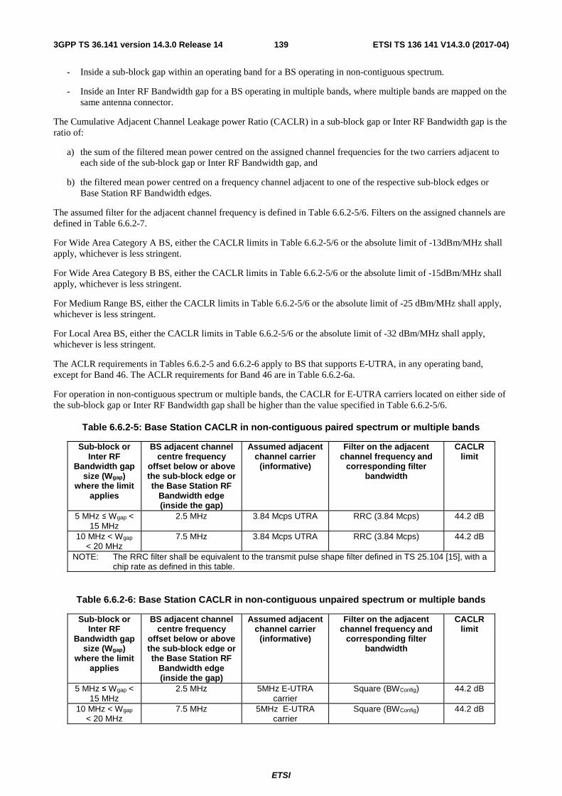
ETSI
ETSI TS 136 141 V14.3.0 (2017-04)1393GPP TS 36.141 version 14.3.0 Release 14
- Inside a sub-block gap within an operating band for a BS operating in non-contiguous spectrum.
- Inside an Inter RF Bandwidth gap for a BS operating in multiple bands, where multiple bands are mapped on the same antenna connector.
The Cumulative Adjacent Channel Leakage power Ratio (CACLR) in a sub-block gap or Inter RF Bandwidth gap is the ratio of:
a) the sum of the filtered mean power centred on the assigned channel frequencies for the two carriers adjacent to each side of the sub-block gap or Inter RF Bandwidth gap, and
b) the filtered mean power centred on a frequency channel adjacent to one of the respective sub-block edges or Base Station RF Bandwidth edges.
The assumed filter for the adjacent channel frequency is defined in Table 6.6.2-5/6. Filters on the assigned channels are defined in Table 6.6.2-7.
For Wide Area Category A BS, either the CACLR limits in Table 6.6.2-5/6 or the absolute limit of -13dBm/MHz shall apply, whichever is less stringent.
For Wide Area Category B BS, either the CACLR limits in Table 6.6.2-5/6 or the absolute limit of -15dBm/MHz shall apply, whichever is less stringent.
For Medium Range BS, either the CACLR limits in Table 6.6.2-5/6 or the absolute limit of -25 dBm/MHz shall apply, whichever is less stringent.
For Local Area BS, either the CACLR limits in Table 6.6.2-5/6 or the absolute limit of -32 dBm/MHz shall apply, whichever is less stringent.
The ACLR requirements in Tables 6.6.2-5 and 6.6.2-6 apply to BS that supports E-UTRA, in any operating band, except for Band 46. The ACLR requirements for Band 46 are in Table 6.6.2-6a.
For operation in non-contiguous spectrum or multiple bands, the CACLR for E-UTRA carriers located on either side of the sub-block gap or Inter RF Bandwidth gap shall be higher than the value specified in Table 6.6.2-5/6.
Table 6.6.2-5: Base Station CACLR in non-contiguous paired spectrum or multiple bands
Sub-block or Inter RF
Bandwidth gap size (Wgap)
where the limit applies
BS adjacent channel centre frequency
offset below or above the sub-block edge or the Base Station RF
Bandwidth edge (inside the gap)
Assumed adjacent channel carrier
(informative)
Filter on the adjacent channel frequency and
corresponding filter bandwidth
CACLR limit
5 MHz ≤ Wgap < 15 MHz
2.5 MHz 3.84 Mcps UTRA RRC (3.84 Mcps) 44.2 dB
10 MHz < Wgap < 20 MHz
7.5 MHz 3.84 Mcps UTRA RRC (3.84 Mcps) 44.2 dB
NOTE: The RRC filter shall be equivalent to the transmit pulse shape filter defined in TS 25.104 [15], with a chip rate as defined in this table.
Table 6.6.2-6: Base Station CACLR in non-contiguous unpaired spectrum or multiple bands
Sub-block or Inter RF
Bandwidth gap size (Wgap)
where the limit applies
BS adjacent channel centre frequency
offset below or above the sub-block edge or the Base Station RF
Bandwidth edge (inside the gap)
Assumed adjacent channel carrier
(informative)
Filter on the adjacent channel frequency and
corresponding filter bandwidth
CACLR limit
5 MHz ≤ Wgap < 15 MHz
2.5 MHz 5MHz E-UTRA carrier
Square (BWConfig) 44.2 dB
10 MHz < Wgap < 20 MHz
7.5 MHz 5MHz E-UTRA carrier
Square (BWConfig) 44.2 dB

ETSI
ETSI TS 136 141 V14.3.0 (2017-04)1403GPP TS 36.141 version 14.3.0 Release 14
For operation in non-contiguous spectrum in Band 46, the CACLR for E-UTRA carriers located on either side of the sub-block gap shall be higher than the value specified in Table 6.6.2-6a.
Table 6.6.2-6a: Base Station CACLR in non-contiguous spectrum in Band 46
Sub-block gap size (Wgap)
where the limit applies
BS adjacent channel centre frequency
offset below or above the sub-block edge
(inside the gap)
Assumed adjacent channel carrier
(informative)
Filter on the adjacent channel frequency and
corresponding filter bandwidth
CACLR limit
20 MHz ≤ Wgap < 60 MHz
10 MHz 20MHz E-UTRA carrier
Square (BWConfig) 34.2 dB
40 MHz < Wgap < 80 MHz
30 MHz 20MHz E-UTRA carrier
Square (BWConfig) 34.2 dB
Table 6.6.2-7: Filter parameters for the assigned channel
RAT of the carrier adjacent to the sub-block or Inter RF
Bandwidth gap
Filter on the assigned channel frequency and corresponding filter bandwidth
E-UTRA E-UTRA of same BW
NOTE: If the above Test Requirements differ from the Minimum Requirement then the Test Tolerance applied for this test is non-zero. The Test Tolerance for this test and the explanation of how the Minimum Requirement has been relaxed by the Test Tolerance are given in Annex G.
6.6.3 Operating band unwanted emissions
6.6.3.1 Definition and applicability
Unless otherwise stated, the Operating band unwanted emission limits are defined from 10 MHz below the lowest frequency of each supported downlink operating band up to 10 MHz above the highest frequency of each supported downlink operating band (see Table 5.5-1).
The requirements shall apply whatever the type of transmitter considered (single carrier, multi-carrier and/or CA) and for all transmission modes foreseen by the manufacturer's specification. In addition, for a BS operating in non-contiguous spectrum, the requirements apply inside any sub-block gap. In addition, for a BS operating in multiple bands, the requirements apply inside any Inter RF Bandwidth gap.
For BS capable of multi-band operation where multiple bands are mapped on separate antenna connectors, the single-band requirements apply and the cumulative evaluation of the emission limit in the Inter RF Bandwidth gap are not applicable.
For a BS supporting E-UTRA with guard band NB-IoT operation, the Operating band unwanted emissions requirements apply to E-UTRA carrier with channel bandwidth larger than or equal to 5 MHz.
The unwanted emission limits in the part of the downlink operating band that falls in the spurious domain are consistent with ITU-R Recommendation SM.329 [5].

ETSI
ETSI TS 136 141 V14.3.0 (2017-04)1413GPP TS 36.141 version 14.3.0 Release 14
For a multicarrier E-UTRA BS or BS configured for intra-band contiguous or non-contiguous carrier aggregation the definitions above apply to the lower edge of the carrier transmitted at the lowest carrier frequency and the upper edge of the carrier transmitted at the highest carrier frequency within a specified operating band.
For Wide Area BS, the requirements of either subclause 6.6.3.5.1 (Category A limits) or subclause 6.6.3.5.2 (Category B limits) shall apply.
For Local Area BS, the requirements of subclause 6.6.3.5.2A shall apply (Category A and B).
For Home BS, the requirements of subclause 6.6.3.5.2B shall apply (Category A and B).
For Medium Range BS, the requirements in subclause 6.6.3.5.2C shall apply (Category A and B).
The application of either Category A or Category B limits shall be the same as for Transmitter spurious emissions (Mandatory Requirements) in subclause 6.6.4.5.
For Category B Operating band unwanted emissions, there are two options for the limits that may be applied regionally. Either the limits in subclause 6.6.3.5.2.1 or subclause 6.6.3.5.2.2 shall be applied.
The requirements of suclauses 6.6.3.5.1 and 6.6.3.5.2 apply to BS that supports E-UTRA with NB-IoT (in band and/or guard band). The requirements for BS that supports standalone NB-IoT are in subclause 6.6.3.5.2E.
6.6.3.2 Minimum Requirement
The minimum requirement is in TS 36.104 [2] subclause 6.6.3.
6.6.3.3 Test purpose
This test measures the emissions of the BS, close to the assigned channel bandwidth of the wanted signal, while the transmitter is in operation.
6.6.3.4 Method of test
6.6.3.4.1 Initial conditions
Test environment: normal; see Annex D.2.
RF channels to be tested for single carrier: B, M and T; see subclause 4.7.
Base Station RF Bandwidth position to be tested for multi-carrier and/or CA: BRFBW, MRFBW and TRFBW in single-band operation, see subclause 4.7.1; BRFBW_T’RFBW and B’RFBW_TRFBW in multi-band operation, see subclause 4.7.1.
1) Connect the signal analyzer to the base station antenna connector as shown in Annex I.1.1.
As a general rule, the resolution bandwidth of the measuring equipment should be equal to the measurement bandwidth. However, to improve measurement accuracy, sensitivity, efficiency and avoiding e.g. carrier leakage, the resolution bandwidth may be smaller than the measurement bandwidth. When the resolution bandwidth is smaller than the measurement bandwidth, the result should be integrated over the measurement bandwidth in order to obtain the equivalent noise bandwidth of the measurement bandwidth.
2) Detection mode: True RMS.
6.6.3.4.2 Procedure
1) For a E-UTRA BS declared to be capable of single carrier operation only, set the BS transmission at manufacturer’s declared rated output power. Channel set-up shall be according to E-TM 1.1.
For a E-UTRA BS declared to be capable of multi-carrier and/or CA operation, set the base station to transmit according to E-TM1.1 on all carriers configured using the applicable test configuration and corresponding power setting specified in sub-clause 4.10 and 4.11.
For a E-UTRA BS declared to be capable of NB-IoT in-band operation, start transmission according to [E-TM1.1] with the NB-IoT PRB constructed according to N-TM at manufacturer’s declared rated output power.

ETSI
ETSI TS 136 141 V14.3.0 (2017-04)1423GPP TS 36.141 version 14.3.0 Release 14
For a E-UTRA BS declared to be capable of NB-IoT guard-band operation, start transmission according to E-TM1.1 with the NB-IoT PRB constructed according to N-TM at manufacturer’s declared rated output power.
For a NB-IoT BS declared to be capable of single carrier operation, start transmission according to N-TM at manufacturer’s declared rated output power.
For a NB-IoT BS declared to be capable of multi-carrier in contiguous spectrum operation in single band only, start transmission according to N-TM on all carriers configured using in the applicable test configuration and corresponding power setting specified in sub-clause 4.10 and 4.11.
For a E-UTRA and NB-IoT standalone BS declared to be capable of multi-carrier in contiguous spectrum operation in single band only, start transmission according to E-TM1.1 on all E-UTRA carriers and N-TM on all NB-IoT carriers configured using in the applicable test configuration and corresponding power setting specified in sub-clause 4.10 and 4.11.
2) Step the centre frequency of the measurement filter in contiguous steps and measure the emission within the specified frequency ranges with the specified measurement bandwidth. For BS operating in multiple bands or non-contiguous spectrum, the emission within the Inter RF Bandwidth or sub-block gap shall be measured using the specified measurement bandwidth from the closest RF Bandwidth or sub block edge.
3) For E-UTRA, repeat the test with the channel set-up according to E-TM 1.2
In addition, for a multi-band capable BS, the following step shall apply:
4) For multi-band capable BS and single band tests, repeat the steps above per involved band where single band test configurations and test models shall apply with no carrier activated in the other band. For multi-band capable BS with separate antenna connector, the antenna connector not being under test in case of single-band or multi-band test shall be terminated.
6.6.3.5 Test requirement
The measurement results in step 2 of 6.6.3.4.2 shall not exceed the maximum levels specified in the tables below, where:
- Δf is the separation between the channel edge frequency and the nominal -3dB point of the measuring filter closest to the carrier frequency.
- f_offset is the separation between the channel edge frequency and the centre of the measuring filter.
- f_offsetmax is the offset to the frequency 10 MHz outside the downlink operating band.
- Δfmax is equal to f_offsetmax minus half of the bandwidth of the measuring filter.
For BS operating in multiple bands, inside any Inter RF Bandwidth gaps with Wgap < 20 MHz, emissions shall not exceed the cumulative sum of the test requirements specified at the Base Station RF Bandwidth edges on each side of the Inter RF Bandwidth gap. The test requirement for Base Station RF Bandwidth edge is specified in Tables 6.6.3.5.1-1 to 6.6.3.5.3-3 below, where in this case:
- Δf is the separation between the Base Station RF Bandwidth edge frequency and the nominal -3 dB point of the measuring filter closest to the Base Station RF Bandwidth edge.
- f_offset is the separation between the Base Station RF Bandwidth edge frequency and the centre of the measuring filter.
- f_offsetmax is equal to the Inter RF Bandwidth gap minus half of the bandwidth of the measuring filter.
- Δfmax is equal to f_offsetmax minus half of the bandwidth of the measuring filter.
For BS capable of multi-band operation where multiple bands are mapped on the same antenna connector, the operating band unwanted emission limits apply also in a supported operating band without any carrier transmitted, in the case where there are carrier(s) transmitted in other supported operating band(s). In this case where there is no carrier transmitted in an operating band, the operating band unwanted emission limit, as defined in the tables of the present subclause for the largest frequency offset (Δfmax), of a band where there is no carrier transmitted shall apply from 10 MHz below the lowest frequency, up to 10 MHz above the highest frequency of the supported downlink operating band

ETSI
ETSI TS 136 141 V14.3.0 (2017-04)1433GPP TS 36.141 version 14.3.0 Release 14
without any carrier transmitted. And, no cumulative limit is applied in the inter-band gap between a supported downlink operating band with carrier(s) transmitted and a supported downlink operating band without any carrier transmitted.
In addition inside any sub-block gap for a BS operating in non-contiguous spectrum, measurement results shall not exceed the cumulative sum of the test requirements specified for the adjacent sub blocks on each side of the sub block gap. The test requirement for each sub block is specified in Tables 6.6.3.5.1-1 to 6.6.3.5.3-3 below, where in this case:
- Δf is the separation between the sub block edge frequency and the nominal -3 dB point of the measuring filter closest to the sub block edge.
- f_offset is the separation between the sub block edge frequency and the centre of the measuring filter.
- f_offsetmax is equal to the sub block gap bandwidth minus half of the bandwidth of the measuring filter.
- Δfmax is equal to f_offsetmax minus half of the bandwidth of the measuring filter.
6.6.3.5.1 Test requirements for Wide Area BS (Category A)
For E-UTRA BS operating in Bands 5, 6, 8, 12, 13, 14, 17, 18, 19, 26, 27, 28, 29, 31, 44 emissions shall not exceed the maximum levels specified in Tables 6.6.3.5.1-1 to 6.6.3.5.1-3.
Table 6.6.3.5.1-1: Wide Area BS operating band unwanted emission limits for 1.4 MHz channel bandwidth (E-UTRA bands <1GHz) for Category A
Frequency offset of measurement
filter -3dB point, Δf
Frequency offset of measurement filter centre
frequency, f_offset
Test requirement (Note 1, 2) Measurement bandwidth
(Note 3)
0 MHz ≤ Δf < 1.4 MHz 0.05 MHz ≤ f_offset < 1.45 MHz dBMHz
offsetfdBm ⎟
⎠
⎞⎜⎝
⎛ −⋅−+ 05.0_
4.1
100.5
100 kHz
1.4 MHz ≤ Δf < 2.8 MHz 1.45 MHz ≤ f_offset < 2.85 MHz -9.5 dBm 100 kHz 2.8 MHz ≤ Δf ≤ Δfmax 2.85 MHz ≤ f_offset < f_offsetmax -13 dBm 100 kHz
NOTE 1: For a BS supporting non-contiguous spectrum operation within any operating band the test requirement within sub-block gaps is calculated as a cumulative sum of contributions from adjacent sub blocks on each side of the sub block gap. Exception is Δf ≥ 10MHz from both adjacent sub blocks on each side of the sub-block gap, where the test requirement within sub-block gaps shall be -13dBm/100kHz.
NOTE 2: For BS supporting multi-band operation with Inter RF Bandwidth gap < 20MHz the test requirement within the Inter RF Bandwidth gaps is calculated as a cumulative sum of contributions from adjacent sub-blocks or RF Bandwidth on each side of the Inter RF Bandwidth gap.
Table 6.6.3.5.1-2: Wide Area BS operating band unwanted emission limits for 3 MHz channel bandwidth (E-UTRA bands <1GHz) for Category A
Frequency offset of measurement
filter -3dB point, Δf
Frequency offset of measurement filter centre
frequency, f_offset
Test requirement (Note 1, 2) Measurement bandwidth
(Note 3) 0 MHz ≤ Δf < 3 MHz 0.05 MHz ≤ f_offset < 3.05 MHz
dBMHz
offsetfdBm ⎟
⎠
⎞⎜⎝
⎛ −⋅−− 05.0_
3
103.5
100 kHz
3 MHz ≤ Δf < 6 MHz 3.05 MHz ≤ f_offset < 6.05 MHz -13.5 dBm 100 kHz 6 MHz ≤ Δf ≤ Δfmax 6.05 MHz ≤ f_offset < f_offsetmax -13 dBm 100 kHz
NOTE 1: For a BS supporting non-contiguous spectrum operation within any operating band the test requirement within sub-block gaps is calculated as a cumulative sum of contributions from adjacent sub blocks on each side of the sub block gap. Exception is Δf ≥ 10MHz from both adjacent sub blocks on each side of the sub-block gap, where the test requirement within sub-block gaps shall be -13dBm/100kHz.
NOTE 2: For BS supporting multi-band operation with Inter RF Bandwidth gap < 20MHz the test requirement within the Inter RF Bandwidth gaps is calculated as a cumulative sum of contributions from adjacent sub-blocks or RF Bandwidth on each side of the Inter RF Bandwidth gap.

ETSI
ETSI TS 136 141 V14.3.0 (2017-04)1443GPP TS 36.141 version 14.3.0 Release 14
Table 6.6.3.5.1-3: Wide Area BS operating band unwanted emission limits for 5, 10, 15 and 20 MHz channel bandwidth (E-UTRA bands <1GHz) for Category A
Frequency offset of measurement
filter -3dB point, Δf
Frequency offset of measurement filter centre
frequency, f_offset
Test requirement (Note 1, 2) Measurement bandwidth
(Note 3) 0 MHz ≤ Δf < 5 MHz 0.05 MHz ≤ f_offset < 5.05 MHz
dBMHz
offsetfdBm ⎟
⎠
⎞⎜⎝
⎛ −⋅−− 05.0_
5
75.5
100 kHz
5 MHz ≤ Δf < min(10 MHz, Δfmax)
5.05 MHz ≤ f_offset < min(10.05 MHz, f_offsetmax)
-12.5 dBm 100 kHz
10 MHz ≤ Δf ≤ Δfmax 10.05 MHz ≤ f_offset < f_offsetmax -13 dBm (Note 5) 100 kHz NOTE 1: For a BS supporting non-contiguous spectrum operation within any operating band the test requirement within
sub-block gaps is calculated as a cumulative sum of contributions from adjacent sub blocks on each side of the sub block gap. Exception is Δf ≥ 10MHz from both adjacent sub blocks on each side of the sub-block gap, where the test requirement within sub-block gaps shall be -13dBm/100kHz.
NOTE 2: For BS supporting multi-band operation with Inter RF Bandwidth gap < 20MHz the test requirement within the Inter RF Bandwidth gaps is calculated as a cumulative sum of contributions from adjacent sub-blocks or RF Bandwidth on each side of the Inter RF Bandwidth gap.
For E-UTRA BS operating in Bands 1, 2, 3, 4, 7, 9, 10, 11, 21, 23, 24, 25, 30, 32, 33, 34, 35, 36, 37, 38, 39, 40, 41, 45, 48, 65, 66, 69, 70, emissions shall not exceed the maximum levels specified in Tables 6.6.3.5.1-4, 6.6.3.5.1-5 and 6.6.3.5.1-6:
For E-UTRA BS operating in Bands 22, 42, 43, emissions shall not exceed the maximum levels specified in Tables 6.6.3.5.1-4a, 6.6.3.5.1-5a and 6.6.3.5.1-6a:
Table 6.6.3.5.1-4: Wide Area BS operating band unwanted emission limits for 1.4 MHz channel bandwidth (1GHz < E-UTRA bands ≤ 3GHz) for Category A
Frequency offset of measurement
filter -3dB point, Δf
Frequency offset of measurement filter centre
frequency, f_offset
Test requirement (Note 1, 2) Measurement bandwidth
(Note 3)
0 MHz ≤ Δf < 1.4 MHz 0.05 MHz ≤ f_offset < 1.45 MHz dBMHz
offsetfdBm ⎟
⎠
⎞⎜⎝
⎛ −⋅−+ 05.0_
4.1
100.5
100 kHz
1.4 MHz ≤ Δf < 2.8 MHz 1.45 MHz ≤ f_offset < 2.85 MHz -9.5 dBm 100 kHz 2.8 MHz ≤ Δf ≤ Δfmax 3.3 MHz ≤ f_offset < f_offsetmax -13 dBm 1MHz
NOTE 1: For a BS supporting non-contiguous spectrum operation within any operating band the test requirement within sub-block gaps is calculated as a cumulative sum of contributions from adjacent sub blocks on each side of the sub block gap, where the contribution from the far-end sub-block shall be scaled according to the measurement bandwidth of the near-end sub-block. Exception is Δf ≥ 10MHz from both adjacent sub blocks on each side of the sub-block gap, where the test requirement within sub-block gaps shall be -13dBm/1MHz.
NOTE 2: For BS supporting multi-band operation with Inter RF Bandwidth gap < 20MHz the test requirement within the Inter RF Bandwidth gaps is calculated as a cumulative sum of contributions from adjacent sub-blocks or RF Bandwidth on each side of the Inter RF Bandwidth gap, where the contribution from the far-end sub-block or RF Bandwidth shall be scaled according to the measurement bandwidth of the near-end sub-block or RF Bandwidth.

ETSI
ETSI TS 136 141 V14.3.0 (2017-04)1453GPP TS 36.141 version 14.3.0 Release 14
Table 6.6.3.5.1-4a: Wide Area BS operating band unwanted emission limits for 1.4 MHz channel bandwidth (E-UTRA bands >3GHz) for Category A
Frequency offset of measurement
filter -3dB point, Δf
Frequency offset of measurement filter centre
frequency, f_offset
Test requirement (Note 1, 2) Measurement bandwidth
(Note 3)
0 MHz ≤ Δf < 1.4 MHz 0.05 MHz ≤ f_offset < 1.45 MHz dBMHz
offsetfdBm ⎟
⎠
⎞⎜⎝
⎛ −⋅−+ 05.0_
4.1
100.8
100 kHz
1.4 MHz ≤ Δf < 2.8 MHz 1.45 MHz ≤ f_offset < 2.85 MHz -9.2 dBm 100 kHz 2.8 MHz ≤ Δf ≤ Δfmax 3.3 MHz ≤ f_offset < f_offsetmax -13 dBm 1MHz
NOTE 1: For a BS supporting non-contiguous spectrum operation within any operating band the test requirement within sub-block gaps is calculated as a cumulative sum of contributions from adjacent sub blocks on each side of the sub block gap, where the contribution from the far-end sub-block shall be scaled according to the measurement bandwidth of the near-end sub-block. Exception is Δf ≥ 10MHz from both adjacent sub blocks on each side of the sub-block gap, where the test requirement within sub-block gaps shall be -13dBm/1MHz.
NOTE 2: For BS supporting multi-band operation with Inter RF Bandwidth gap < 20MHz the test requirement within the Inter RF Bandwidth gaps is calculated as a cumulative sum of contributions from adjacent sub-blocks or RF Bandwidth on each side of the Inter RF Bandwidth gap, where the contribution from the far-end sub-block or RF Bandwidth shall be scaled according to the measurement bandwidth of the near-end sub-block or RF Bandwidth.
Table 6.6.3.5.1-5: Wide Area BS operating band unwanted emission limits for 3 MHz channel bandwidth (1GHz < E-UTRA bands ≤ 3GHz) for Category A
Frequency offset of measurement
filter -3dB point, Δf
Frequency offset of measurement filter centre
frequency, f_offset
Test requirement (Note 1, 2) Measurement bandwidth
(Note 3)
0 MHz ≤ Δf < 3 MHz 0.05 MHz ≤ f_offset < 3.05 MHz dBMHz
offsetfdBm ⎟
⎠
⎞⎜⎝
⎛ −⋅−− 05.0_
3
103.5
100 kHz
3 MHz ≤ Δf < 6 MHz 3.05 MHz ≤ f_offset < 6.05 MHz -13.5 dBm 100 kHz 6 MHz ≤ Δf ≤ Δfmax 6.5 MHz ≤ f_offset < f_offsetmax -13 dBm 1MHz
NOTE 1: For a BS supporting non-contiguous spectrum operation within any operating band the test requirement within sub-block gaps is calculated as a cumulative sum of contributions from adjacent sub blocks on each side of the sub block gap, where the contribution from the far-end sub-block shall be scaled according to the measurement bandwidth of the near-end sub-block. Exception is Δf ≥ 10MHz from both adjacent sub blocks on each side of the sub-block gap, where the test requirement within sub-block gaps shall be -13dBm/1MHz.
NOTE 2: For BS supporting multi-band operation with Inter RF Bandwidth gap < 20MHz the test requirement within the Inter RF Bandwidth gaps is calculated as a cumulative sum of contributions from adjacent sub-blocks or RF Bandwidth on each side of the Inter RF Bandwidth gap, where the contribution from the far-end sub-block or RF Bandwidth shall be scaled according to the measurement bandwidth of the near-end sub-block or RF Bandwidth.

ETSI
ETSI TS 136 141 V14.3.0 (2017-04)1463GPP TS 36.141 version 14.3.0 Release 14
Table 6.6.3.5.1-5a: Wide Area BS operating band unwanted emission limits for 3 MHz channel bandwidth (E-UTRA bands >3GHz) for Category A
Frequency offset of measurement
filter -3dB point, Δf
Frequency offset of measurement filter centre
frequency, f_offset
Test requirement (Note 1, 2) Measurement bandwidth
(Note 3)
0 MHz ≤ Δf < 3 MHz 0.05 MHz ≤ f_offset < 3.05 MHz dBMHz
offsetfdBm ⎟
⎠
⎞⎜⎝
⎛ −⋅−− 05.0_
3
103.2
100 kHz
3 MHz ≤ Δf < 6 MHz 3.05 MHz ≤ f_offset < 6.05 MHz -13.2 dBm 100 kHz 6 MHz ≤ Δf ≤ Δfmax 6.5 MHz ≤ f_offset < f_offsetmax -13 dBm 1MHz
NOTE 1: For a BS supporting non-contiguous spectrum operation within any operating band the test requirement within sub-block gaps is calculated as a cumulative sum of contributions from adjacent sub blocks on each side of the sub block gap, where the contribution from the far-end sub-block shall be scaled according to the measurement bandwidth of the near-end sub-block. Exception is Δf ≥ 10MHz from both adjacent sub blocks on each side of the sub-block gap, where the test requirement within sub-block gaps shall be -13dBm/1MHz.
NOTE 2: For BS supporting multi-band operation with Inter RF Bandwidth gap < 20MHz the test requirement within the Inter RF Bandwidth gaps is calculated as a cumulative sum of contributions from adjacent sub-blocks or RF Bandwidth on each side of the Inter RF Bandwidth gap, where the contribution from the far-end sub-block or RF Bandwidth shall be scaled according to the measurement bandwidth of the near-end sub-block or RF Bandwidth.
Table 6.6.3.5.1-6: Wide Area BS operating band unwanted emission limits for 5, 10, 15 and 20 MHz channel bandwidth (1GHz < E-UTRA bands ≤ 3GHz) for Category A
Frequency offset of measurement
filter -3dB point, Δf
Frequency offset of measurement filter centre
frequency, f_offset
Test requirement (Note 1, 2) Measurement bandwidth
(Note 3) 0 MHz ≤ Δf < 5 MHz 0.05 MHz ≤ f_offset < 5.05 MHz
dBMHz
offsetfdBm ⎟
⎠
⎞⎜⎝
⎛ −⋅−− 05.0_
5
75.5
100 kHz
5 MHz ≤ Δf < min(10 MHz, Δfmax)
5.05 MHz ≤ f_offset < min(10.05 MHz, f_offsetmax)
-12.5 dBm 100 kHz
10 MHz ≤ Δf ≤ Δfmax 10.5 MHz ≤ f_offset < f_offsetmax -13 dBm (Note 6) 1MHz NOTE 1: For a BS supporting non-contiguous spectrum operation within any operating band the test requirement within
sub-block gaps is calculated as a cumulative sum of contributions from adjacent sub blocks on each side of the sub block gap, where the contribution from the far-end sub-block shall be scaled according to the measurement bandwidth of the near-end sub-block. Exception is Δf ≥ 10MHz from both adjacent sub blocks on each side of the sub-block gap, where the test requirement within sub-block gaps shall be -13dBm/1MHz.
NOTE 2: For BS supporting multi-band operation with Inter RF Bandwidth gap < 20MHz the test requirement within the Inter RF Bandwidth gaps is calculated as a cumulative sum of contributions from adjacent sub-blocks or RF Bandwidth on each side of the Inter RF Bandwidth gap, where the contribution from the far-end sub-block or RF Bandwidth shall be scaled according to the measurement bandwidth of the near-end sub-block or RF Bandwidth.

ETSI
ETSI TS 136 141 V14.3.0 (2017-04)1473GPP TS 36.141 version 14.3.0 Release 14
Table 6.6.3.5.1-6a: Wide Area BS operating band unwanted emission limits for 5, 10, 15 and 20 MHz channel bandwidth (E-UTRA bands >3GHz) for Category A
Frequency offset of measurement
filter -3dB point, Δf
Frequency offset of measurement filter centre
frequency, f_offset
Test requirement (Note 1, 2) Measurement bandwidth
(Note 3) 0 MHz ≤ Δf < 5 MHz 0.05 MHz ≤ f_offset < 5.05 MHz
dBMHz
offsetfdBm ⎟
⎠
⎞⎜⎝
⎛ −⋅−− 05.0_
5
75.2
100 kHz
5 MHz ≤ Δf < min(10 MHz, Δfmax)
5.05 MHz ≤ f_offset < min(10.05 MHz, f_offsetmax)
-12.2 dBm 100 kHz
10 MHz ≤ Δf ≤ Δfmax 10.5 MHz ≤ f_offset < f_offsetmax -13 dBm (Note 6) 1MHz NOTE 1: For a BS supporting non-contiguous spectrum operation within any operating band the test requirement within
sub-block gaps is calculated as a cumulative sum of contributions from adjacent sub blocks on each side of the sub block gap, where the contribution from the far-end sub-block shall be scaled according to the measurement bandwidth of the near-end sub-block. Exception is Δf ≥ 10MHz from both adjacent sub blocks on each side of the sub-block gap, where the test requirement within sub-block gaps shall be -13dBm/1MHz.
NOTE 2: For BS supporting multi-band operation with Inter RF Bandwidth gap < 20MHz the test requirement within the Inter RF Bandwidth gaps is calculated as a cumulative sum of contributions from adjacent sub-blocks or RF Bandwidth on each side of the Inter RF Bandwidth gap, where the contribution from the far-end sub-block or RF Bandwidth shall be scaled according to the measurement bandwidth of the near-end sub-block or RF Bandwidth.
6.6.3.5.2 Test requirements for Wide Area BS (Category B)
For Category B Operating band unwanted emissions, there are two options for the limits that may be applied regionally. Either the limits in subclause 6.6.3.5.2.1 or subclause 6.6.3.5.2.2 shall be applied.
6.6.3.5.2.1 Category B test requirements (Option 1)
For E-UTRA BS operating in Bands 5, 8, 12, 13, 14, 17, 20, 26, 27, 28, 29, 31, 44, 67, 68 emissions shall not exceed the maximum levels specified in Tables 6.6.3.5.2.1-1 to 6.6.3.5.2.1-3:
Table 6.6.3.5.2.1-1: Wide Area BS operating band unwanted emission limits for 1.4 MHz channel bandwidth (E-UTRA bands <1GHz) for Category B
Frequency offset of measurement
filter -3dB point, Δf
Frequency offset of measurement filter centre
frequency, f_offset
Test requirement (Note 1, 2) Measurement bandwidth
(Note 3)
0 MHz ≤ Δf < 1.4 MHz 0.05 MHz ≤ f_offset < 1.45 MHz dBMHz
offsetfdBm ⎟
⎠
⎞⎜⎝
⎛ −⋅−+ 05.0_
4.1
100.5
100 kHz
1.4 MHz ≤ Δf < 2.8 MHz 1.45 MHz ≤ f_offset < 2.85 MHz -9.5 dBm 100 kHz 2.8 MHz ≤ Δf ≤ Δfmax 2.85 MHz ≤ f_offset < f_offsetmax -16 dBm 100 kHz
NOTE 1: For a BS supporting non-contiguous spectrum operation within any operating band the test requirement within sub-block gaps is calculated as a cumulative sum of contributions from adjacent sub blocks on each side of the sub block gap. Exception is Δf ≥ 10MHz from both adjacent sub blocks on each side of the sub-block gap, where the test requirement within sub-block gaps shall be -16dBm/100kHz.
NOTE 2: For BS supporting multi-band operation with Inter RF Bandwidth gap < 20MHz the test requirement within the Inter RF Bandwidth gaps is calculated as a cumulative sum of contributions from adjacent sub-blocks or RF Bandwidth on each side of the Inter RF Bandwidth gap.

ETSI
ETSI TS 136 141 V14.3.0 (2017-04)1483GPP TS 36.141 version 14.3.0 Release 14
Table 6.6.3.5.2.1-2: Wide Area BS operating band unwanted emission limits for 3 MHz channel bandwidth (E-UTRA bands <1GHz) for Category B
Frequency offset of measurement
filter -3dB point, Δf
Frequency offset of measurement filter centre
frequency, f_offset
Test requirement (Note 1, 2) Measurement bandwidth
(Note 3)
0 MHz ≤ Δf < 3 MHz 0.05 MHz ≤ f_offset < 3.05 MHz dBMHz
offsetfdBm ⎟
⎠
⎞⎜⎝
⎛ −⋅−− 05.0_
3
103.5
100 kHz
3 MHz ≤ Δf < 6 MHz 3.05 MHz ≤ f_offset < 6.05 MHz -13.5 dBm 100 kHz 6 MHz ≤ Δf ≤ Δfmax 6.05 MHz ≤ f_offset < f_offsetmax -16 dBm 100 kHz
NOTE 1: For a BS supporting non-contiguous spectrum operation within any operating band the test requirement within sub-block gaps is calculated as a cumulative sum of contributions from adjacent sub blocks on each side of the sub block gap. Exception is Δf ≥ 10MHz from both adjacent sub blocks on each side of the sub-block gap, where the test requirement within sub-block gaps shall be -16dBm/100kHz.
NOTE 2: For BS supporting multi-band operation with Inter RF Bandwidth gap < 20MHz the test requirement within the Inter RF Bandwidth gaps is calculated as a cumulative sum of contributions from adjacent sub-blocks or RF Bandwidth on each side of the Inter RF Bandwidth gap.
Table 6.6.3.5.2.1-3: Wide Area BS operating band unwanted emission limits for 5, 10, 15 and 20 MHz channel bandwidth (E-UTRA bands <1GHz) for Category B
Frequency offset of measurement
filter -3dB point, Δf
Frequency offset of measurement filter centre
frequency, f_offset
Test requirement (Note 1, 2) Measurement bandwidth
(Note 3) 0 MHz ≤ Δf < 5 MHz 0.05 MHz ≤ f_offset < 5.05 MHz
dBMHz
offsetfdBm ⎟
⎠
⎞⎜⎝
⎛ −⋅−− 05.0_
5
75.5
100 kHz
5 MHz ≤ Δf < min(10 MHz, Δfmax)
5.05 MHz ≤ f_offset < min(10.05 MHz, f_offsetmax)
-12.5 dBm 100 kHz
10 MHz ≤ Δf ≤ Δfmax 10.05 MHz ≤ f_offset < f_offsetmax -16 dBm (Note 6) 100 kHz NOTE 1: For a BS supporting non-contiguous spectrum operation within any operating band the test requirement within
sub-block gaps is calculated as a cumulative sum of contributions from adjacent sub blocks on each side of the sub block gap. Exception is Δf ≥ 10MHz from both adjacent sub blocks on each side of the sub-block gap, where the test requirement within sub-block gaps shall be -16dBm/100kHz.
NOTE 2: For BS supporting multi-band operation with Inter RF Bandwidth gap < 20MHz the test requirement within the Inter RF Bandwidth gaps is calculated as a cumulative sum of contributions from adjacent sub-blocks or RF Bandwidth on each side of the Inter RF Bandwidth gap.

ETSI
ETSI TS 136 141 V14.3.0 (2017-04)1493GPP TS 36.141 version 14.3.0 Release 14
For E-UTRA BS operating in Bands 1, 2, 3, 4, 7, 10, 25, 30, 33, 34, 35, 36, 37, 38, 39, 40, 41, 45, 48, 65, 66, 69, 70, emissions shall not exceed the maximum levels specified in Tables 6.6.3.5.2.1-4, 6.6.3.5.2.1-5 and 6.6.3.5.2.1-6:
For E-UTRA BS operating in Bands 22, 42, 43, emissions shall not exceed the maximum levels specified in Tables 6.6.3.5.2.1-4a, 6.6.3.5.2.1-5a and 6.6.3.5.2.1-6a:
Table 6.6.3.5.2.1-4: Wide Area BS operating band unwanted emission limits for 1.4 MHz channel bandwidth (1GHz < E-UTRA bands ≤ 3GHz) for Category B
Frequency offset of measurement
filter -3dB point, Δf
Frequency offset of measurement filter centre
frequency, f_offset
Test requirement (Note 1, 2) Measurement bandwidth
(Note 3)
0 MHz ≤ Δf < 1.4 MHz 0.05 MHz ≤ f_offset < 1.45 MHz dBMHz
offsetfdBm ⎟
⎠
⎞⎜⎝
⎛ −⋅−+ 05.0_
4.1
100.5
100 kHz
1.4 MHz ≤ Δf < 2.8 MHz 1.45 MHz ≤ f_offset < 2.85 MHz -9.5 dBm 100 kHz 2.8 MHz ≤ Δf ≤ Δfmax 3.3 MHz ≤ f_offset < f_offsetmax -15 dBm 1MHz
NOTE 1: For a BS supporting non-contiguous spectrum operation within any operating band the test requirement within sub-block gaps is calculated as a cumulative sum of contributions from adjacent sub blocks on each side of the sub block gap, where the contribution from the far-end sub-block shall be scaled according to the measurement bandwidth of the near-end sub-block. Exception is Δf ≥ 10MHz from both adjacent sub blocks on each side of the sub-block gap, where the test requirement within sub-block gaps shall be -15dBm/1MHz.
NOTE 2: For BS supporting multi-band operation with Inter RF Bandwidth gap < 20MHz the test requirement within the Inter RF Bandwidth gaps is calculated as a cumulative sum of contributions from adjacent sub-blocks or RF Bandwidth on each side of the Inter RF Bandwidth gap, where the contribution from the far-end sub-block or RF Bandwidth shall be scaled according to the measurement bandwidth of the near-end sub-block or RF Bandwidth.
Table 6.6.3.5.2.1-4a: Wide Area BS operating band unwanted emission limits for 1.4 MHz channel bandwidth (E-UTRA bands >3GHz) for Category B
Frequency offset of measurement
filter -3dB point, Δf
Frequency offset of measurement filter centre
frequency, f_offset
Test requirement (Note 1, 2) Measurement bandwidth
(Note 3)
0 MHz ≤ Δf < 1.4 MHz 0.05 MHz ≤ f_offset < 1.45 MHz dBMHz
offsetfdBm ⎟
⎠
⎞⎜⎝
⎛ −⋅−+ 05.0_
4.1
100.8
100 kHz
1.4 MHz ≤ Δf < 2.8 MHz 1.45 MHz ≤ f_offset < 2.85 MHz -9.2 dBm 100 kHz 2.8 MHz ≤ Δf ≤ Δfmax 3.3 MHz ≤ f_offset < f_offsetmax -15 dBm 1MHz
NOTE 1: For a BS supporting non-contiguous spectrum operation within any operating band the test requirement within sub-block gaps is calculated as a cumulative sum of contributions from adjacent sub blocks on each side of the sub block gap, where the contribution from the far-end sub-block shall be scaled according to the measurement bandwidth of the near-end sub-block. Exception is Δf ≥ 10MHz from both adjacent sub blocks on each side of the sub-block gap, where the test requirement within sub-block gaps shall be -15dBm/1MHz.
NOTE 2: For BS supporting multi-band operation with Inter RF Bandwidth gap < 20MHz the test requirement within the Inter RF Bandwidth gaps is calculated as a cumulative sum of contributions from adjacent sub-blocks or RF Bandwidth on each side of the Inter RF Bandwidth gap, where the contribution from the far-end sub-block or RF Bandwidth shall be scaled according to the measurement bandwidth of the near-end sub-block or RF Bandwidth.

ETSI
ETSI TS 136 141 V14.3.0 (2017-04)1503GPP TS 36.141 version 14.3.0 Release 14
Table 6.6.3.5.2.1-5: Wide Area BS operating band unwanted emission limits for 3 MHz channel bandwidth (1GHz < E-UTRA bands ≤ 3GHz) for Category B
Frequency offset of measurement
filter -3dB point, Δf
Frequency offset of measurement filter centre
frequency, f_offset
Test requirement (Note 1, 2) Measurement bandwidth
(Note 3)
0 MHz ≤ Δf < 3 MHz 0.05 MHz ≤ f_offset < 3.05 MHz dBMHz
offsetfdBm ⎟
⎠
⎞⎜⎝
⎛ −⋅−− 05.0_
3
103.5
100 kHz
3 MHz ≤ Δf < 6 MHz 3.05 MHz ≤ f_offset < 6.05 MHz -13.5 dBm 100 kHz 6 MHz ≤ Δf ≤ Δfmax 6.5 MHz ≤ f_offset < f_offsetmax -15 dBm 1MHz
NOTE 1: For a BS supporting non-contiguous spectrum operation within any operating band the test requirement within sub-block gaps is calculated as a cumulative sum of contributions from adjacent sub blocks on each side of the sub block gap, where the contribution from the far-end sub-block shall be scaled according to the measurement bandwidth of the near-end sub-block. Exception is Δf ≥ 10MHz from both adjacent sub blocks on each side of the sub-block gap, where the test requirement within sub-block gaps shall be -15dBm/1MHz.
NOTE 2: For BS supporting multi-band operation with Inter RF Bandwidth gap < 20MHz the test requirement within the Inter RF Bandwidth gaps is calculated as a cumulative sum of contributions from adjacent sub-blocks or RF Bandwidth on each side of the Inter RF Bandwidth gap, where the contribution from the far-end sub-block or RF Bandwidth shall be scaled according to the measurement bandwidth of the near-end sub-block or RF Bandwidth.
Table 6.6.3.5.2.1-5a: Wide Area BS operating band unwanted emission limits for 3 MHz channel bandwidth (E-UTRA bands >3GHz) for Category B
Frequency offset of measurement
filter -3dB point, Δf
Frequency offset of measurement filter centre
frequency, f_offset
Test requirement (Note 1, 2) Measurement bandwidth
(Note 3)
0 MHz ≤ Δf < 3 MHz 0.05 MHz ≤ f_offset < 3.05 MHz dBMHz
offsetfdBm ⎟
⎠
⎞⎜⎝
⎛ −⋅−− 05.0_
3
103.2
100 kHz
3 MHz ≤ Δf < 6 MHz 3.05 MHz ≤ f_offset < 6.05 MHz -13.2 dBm 100 kHz 6 MHz ≤ Δf ≤ Δfmax 6.5 MHz ≤ f_offset < f_offsetmax -15 dBm 1MHz
NOTE 1: For a BS supporting non-contiguous spectrum operation within any operating band the test requirement within sub-block gaps is calculated as a cumulative sum of contributions from adjacent sub blocks on each side of the sub block gap, where the contribution from the far-end sub-block shall be scaled according to the measurement bandwidth of the near-end sub-block. Exception is Δf ≥ 10MHz from both adjacent sub blocks on each side of the sub-block gap, where the test requirement within sub-block gaps shall be -15dBm/1MHz.
NOTE 2: For BS supporting multi-band operation with Inter RF Bandwidth gap < 20MHz the test requirement within the Inter RF Bandwidth gaps is calculated as a cumulative sum of contributions from adjacent sub-blocks or RF Bandwidth on each side of the Inter RF Bandwidth gap, where the contribution from the far-end sub-block or RF Bandwidth shall be scaled according to the measurement bandwidth of the near-end sub-block or RF Bandwidth.

ETSI
ETSI TS 136 141 V14.3.0 (2017-04)1513GPP TS 36.141 version 14.3.0 Release 14
Table 6.6.3.5.2.1-6: Wide Area BS operating band unwanted emission limits for 5, 10, 15 and 20 MHz channel bandwidth (1GHz < E-UTRA bands ≤ 3GHz) for Category B
Frequency offset of measurement
filter -3dB point, Δf
Frequency offset of measurement filter centre
frequency, f_offset
Test requirement (Note 1, 2) Measurement bandwidth
(Note 3) 0 MHz ≤ Δf < 5 MHz 0.05 MHz ≤ f_offset < 5.05 MHz
dBMHz
offsetfdBm ⎟
⎠
⎞⎜⎝
⎛ −⋅−− 05.0_
5
75.5
100 kHz
5 MHz ≤ Δf < min(10 MHz, Δfmax)
5.05 MHz ≤ f_offset < min(10.05 MHz, f_offsetmax)
-12.5 dBm 100 kHz
10 MHz ≤ Δf ≤ Δfmax 10.5 MHz ≤ f_offset < f_offsetmax -15 dBm (Note 6) 1MHz NOTE 1: For a BS supporting non-contiguous spectrum operation within any operating band the test requirement within
sub-block gaps is calculated as a cumulative sum of contributions from adjacent sub blocks on each side of the sub block gap, where the contribution from the far-end sub-block shall be scaled according to the measurement bandwidth of the near-end sub-block. Exception is Δf ≥ 10MHz from both adjacent sub blocks on each side of the sub-block gap, where the test requirement within sub-block gaps shall be -15dBm/1MHz.
NOTE 2: For BS supporting multi-band operation with Inter RF Bandwidth gap < 20MHz the test requirement within the Inter RF Bandwidth gaps is calculated as a cumulative sum of contributions from adjacent sub-blocks or RF Bandwidth on each side of the Inter RF Bandwidth gap, where the contribution from the far-end sub-block or RF Bandwidth shall be scaled according to the measurement bandwidth of the near-end sub-block or RF Bandwidth.
Table 6.6.3.5.2.1-6a: Wide Area BS operating band unwanted emission limits for 5, 10, 15 and 20 MHz channel bandwidth (E-UTRA bands >3GHz) for Category B
Frequency offset of measurement
filter -3dB point, Δf
Frequency offset of measurement filter centre
frequency, f_offset
Test requirement (Note 1, 2) Measurement bandwidth
(Note 3) 0 MHz ≤ Δf < 5 MHz 0.05 MHz ≤ f_offset < 5.05 MHz
dBMHz
offsetfdBm ⎟
⎠
⎞⎜⎝
⎛ −⋅−− 05.0_
5
75.2
100 kHz
5 MHz ≤ Δf < min(10 MHz, Δfmax)
5.05 MHz ≤ f_offset < min(10.05 MHz, f_offsetmax)
-12.2 dBm 100 kHz
10 MHz ≤ Δf ≤ Δfmax 10.5 MHz ≤ f_offset < f_offsetmax -15 dBm (Note 6) 1MHz NOTE 1: For a BS supporting non-contiguous spectrum operation within any operating band the test requirement within
sub-block gaps is calculated as a cumulative sum of contributions from adjacent sub blocks on each side of the sub block gap, where the contribution from the far-end sub-block shall be scaled according to the measurement bandwidth of the near-end sub-block. Exception is Δf ≥ 10MHz from both adjacent sub blocks on each side of the sub-block gap, where the test requirement within sub-block gaps shall be -15dBm/1MHz.
NOTE 2: For BS supporting multi-band operation with Inter RF Bandwidth gap < 20MHz the test requirement within the Inter RF Bandwidth gaps is calculated as a cumulative sum of contributions from adjacent sub-blocks or RF Bandwidth on each side of the Inter RF Bandwidth gap, where the contribution from the far-end sub-block or RF Bandwidth shall be scaled according to the measurement bandwidth of the near-end sub-block or RF Bandwidth.
6.6.3.5.2.2 Category B (Option 2)
The limits in this subclause are intended for Europe and may be applied regionally for BS operating in band 1, 3, 8, 32, 33, 34 or 65.
For a BS operating in band 1, 3, 8, 32, 33, 34 or 65, emissions shall not exceed the maximum levels specified in Table 6.6.3.5.2.2-1 below for 5, 10, 15 and 20 MHz channel bandwidth:

ETSI
ETSI TS 136 141 V14.3.0 (2017-04)1523GPP TS 36.141 version 14.3.0 Release 14
Table 6.6.3.5.2.2-1: Regional Wide Area BS operating band unwanted emission limits in band 1, 3, 8, 32, 33, 34 or 65 for 5, 10, 15 and 20 MHz channel bandwidth for Category B
Frequency offset of measurement
filter -3dB point, Δf
Frequency offset of measurement filter centre
frequency, f_offset
Test requirement (Note 1, 2) Measurement bandwidth
(Note 3) 0 MHz ≤ Δf < 0.2 MHz 0.015MHz ≤ f_offset < 0.215MHz -12.5dBm 30 kHz 0.2 MHz ≤ Δf < 1 MHz 0.215MHz ≤ f_offset < 1.015MHz
dBMHz
offsetfdBm ⎟
⎠
⎞⎜⎝
⎛ −⋅−− 215.0_
155.12 30 kHz
(Note 5) 1.015MHz ≤ f_offset < 1.5 MHz -24.5dBm 30 kHz 1 MHz ≤ Δf ≤
min( 10 MHz , Δfmax) 1.5 MHz ≤ f_offset <
min(10.5 MHz, f_offsetmax) -11.5dBm 1 MHz
10 MHz ≤ Δf ≤ Δfmax 10.5 MHz ≤ f_offset < f_offsetmax -15 dBm (Note 6) 1 MHz NOTE 1: For a BS supporting non-contiguous spectrum operation within any operating band the test requirement within
sub-block gaps is calculated as a cumulative sum of contributions from adjacent sub blocks on each side of the sub block gap, where the contribution from the far-end sub-block shall be scaled according to the measurement bandwidth of the near-end sub-block. Exception is Δf ≥ 10MHz from both adjacent sub blocks on each side of the sub-block gap, where the test requirement within sub-block gaps shall be -15dBm/1MHz.
NOTE 2: For BS supporting multi-band operation with Inter RF Bandwidth gap < 20MHz the test requirement within the Inter RF Bandwidth gaps is calculated as a cumulative sum of contributions from adjacent sub-blocks or RF Bandwidth on each side of the Inter RF Bandwidth gap, where the contribution from the far-end sub-block or RF Bandwidth shall be scaled according to the measurement bandwidth of the near-end sub-block or RF Bandwidth.
For a BS operating in band 3, 8 or 65, emissions shall not exceed the maximum levels specified in Table 6.6.3.5.2.2-2 below for 3 MHz channel bandwidth:
Table 6.6.3.5.2.2-2: Regional Wide Area BS operating band unwanted emission limits in band 3, 8 or 65 for 3 MHz channel bandwidth for Category B
Frequency offset of measurement filter -3dB
point, Δf
Frequency offset of measurement filter centre frequency, f_offset
Test requirement (Note 1, 2) Measurement bandwidth
(Note 3) 0 MHz ≤ Δf < 0.05 MHz 0.015 MHz ≤ f_offset < 0.065 MHz
dBMHz
fdBm
offset
⎟⎟⎠
⎞⎜⎜⎝
⎛−⋅− 015.0605.6
30 kHz
0.05 MHz ≤ Δf < 0.15 MHz 0. 065 MHz ≤ f_offset < 0.165 MHz dB
MHz
fdBm
offset
⎟⎟⎠
⎞⎜⎜⎝
⎛−⋅− 065.01605.3
30 kHz
0.15 MHz ≤ Δf < 0.2 MHz 0.165MHz ≤ f_offset < 0.215MHz -12.5dBm 30 kHz 0.2 MHz ≤ Δf < 1 MHz 0.215MHz ≤ f_offset < 1.015MHz
MHz
offsetfdBm ⎜
⎝
⎛ −⋅−− 215.0_
155.12
30 kHz
(Note 5) 1.015MHz ≤ f_offset < 1.5 MHz -24.5dBm 30 kHz 1 MHz ≤ Δf ≤
6 MHz 1.5MHz ≤ f_offset < 6.5 MHz, -11.5dBm 1 MHz
6 MHz ≤ Δf ≤ Δfmax 6.5 MHz ≤ f_offset < f_offsetmax -15 dBm 1 MHz NOTE 1: For a BS supporting non-contiguous spectrum operation within any operating band the test requirement within
sub-block gaps is calculated as a cumulative sum of contributions from adjacent sub blocks on each side of the sub block gap, where the contribution from the far-end sub-block shall be scaled according to the measurement bandwidth of the near-end sub-block. Exception is Δf ≥ 10MHz from both adjacent sub blocks on each side of the sub-block gap, where the test requirement within sub-block gaps shall be -15dBm/1MHz.
NOTE 2: For BS supporting multi-band operation with Inter RF Bandwidth gap < 20MHz the test requirement within the Inter RF Bandwidth gaps is calculated as a cumulative sum of contributions from adjacent sub-blocks or RF Bandwidth on each side of the Inter RF Bandwidth gap, where the contribution from the far-end sub-block or RF Bandwidth shall be scaled according to the measurement bandwidth of the near-end sub-block or RF Bandwidth.

ETSI
ETSI TS 136 141 V14.3.0 (2017-04)1533GPP TS 36.141 version 14.3.0 Release 14
For a BS operating in band 3, 8 or 65, emissions shall not exceed the maximum levels specified in Table 6.6.3.5.2.2-3 below for 1.4 MHz channel bandwidth:
Table 6.6.3.5.2.2-3: Regional Wide Area BS operating band unwanted emission limits in band 3, 8 or 65 for 1.4 MHz channel bandwidth for Category B
Frequency offset of measurement filter -3dB
point, Δf
Frequency offset of measurement filter centre frequency, f_offset
Test requirement (Note 1, 2) Measurement bandwidth
(Note 3) 0 MHz ≤ Δf < 0.05 MHz 0.015 MHz ≤ f_offset < 0.065 MHz
dBMHz
fdBm
offset
⎟⎟⎠
⎞⎜⎜⎝
⎛−⋅− 015.0605.6
30 kHz
0.05 MHz ≤ Δf < 0.15 MHz 0. 065 MHz ≤ f_offset < 0.165 MHz dB
MHz
fdBm
offset
⎟⎟⎠
⎞⎜⎜⎝
⎛−⋅− 065.01605.3
30 kHz
0.15 MHz ≤ Δf < 0.2 MHz 0.165MHz ≤ f_offset < 0.215MHz -12.5 dBm 30 kHz 0.2 MHz ≤ Δf < 1 MHz 0.215MHz ≤ f_offset < 1.015MHz
MHz
offsetfdBm ⎜
⎝
⎛ −⋅−− 215.0_
155.12
30 kHz
(Note 5) 1.015MHz ≤ f_offset < 1.5 MHz -24.5 dBm 30 kHz 1 MHz ≤ Δf ≤ 2.8 MHz 1.5 MHz ≤ f_offset < 3.3 MHz -11.5 dBm 1 MHz 2.8 MHz ≤ Δf ≤ Δfmax 3.3 MHz ≤ f_offset < f_offsetmax -15 dBm 1 MHz
NOTE 1: For a BS supporting non-contiguous spectrum operation within any operating band the test requirement within sub-block gaps is calculated as a cumulative sum of contributions from adjacent sub blocks on each side of the sub block gap, where the contribution from the far-end sub-block shall be scaled according to the measurement bandwidth of the near-end sub-block. Exception is Δf ≥ 10MHz from both adjacent sub blocks on each side of the sub-block gap, where the test requirement within sub-block gaps shall be -15dBm/1MHz.
NOTE 2: For BS supporting multi-band operation with Inter RF Bandwidth gap < 20MHz the test requirement within the Inter RF Bandwidth gaps is calculated as a cumulative sum of contributions from adjacent sub-blocks or RF Bandwidth on each side of the Inter RF Bandwidth gap, where the contribution from the far-end sub-block or RF Bandwidth shall be scaled according to the measurement bandwidth of the near-end sub-block or RF Bandwidth.
6.6.3.5.2A Test requirements for Local Area BS (Category A and B)
For Local Area BS in E-UTRA bands ≤3GHz, emissions shall not exceed the maximum levels specified in Tables 6.6.3.5.2A-1, 6.6.3.5.2A-2 and 6.6.3.5.2A-3.
For Local Area BS in E-UTRA bands >3GHz, emissions shall not exceed the maximum levels specified in Tables 6.6.3.5.2A-1a, 6.6.3.5.2A-2a and 6.6.3.5.2A-3a.
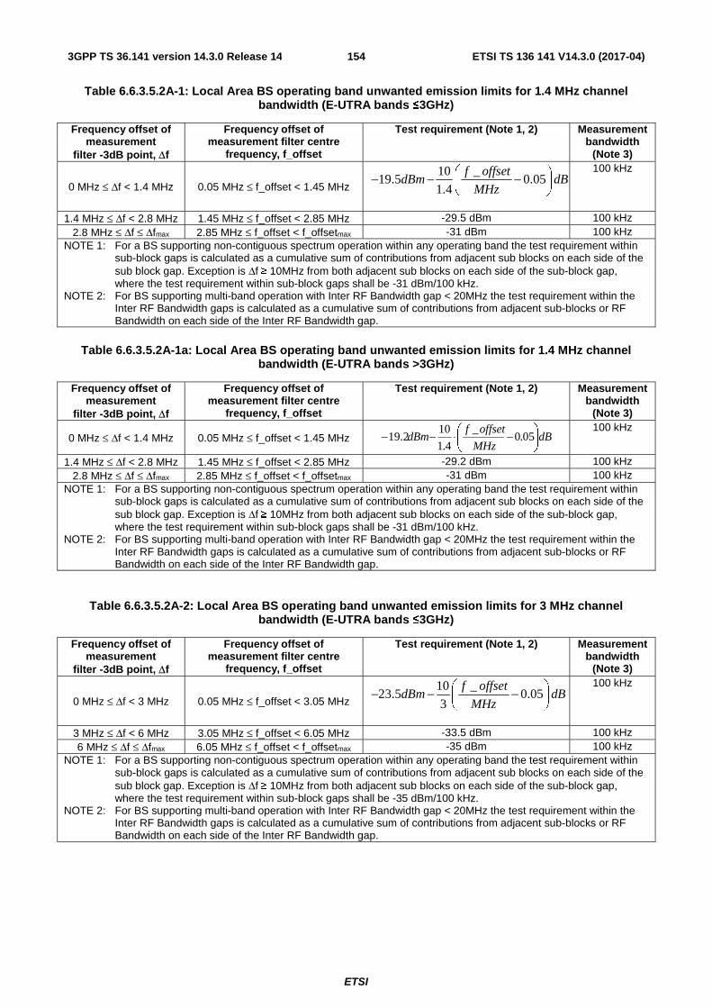
ETSI
ETSI TS 136 141 V14.3.0 (2017-04)1543GPP TS 36.141 version 14.3.0 Release 14
Table 6.6.3.5.2A-1: Local Area BS operating band unwanted emission limits for 1.4 MHz channel bandwidth (E-UTRA bands ≤3GHz)
Frequency offset of measurement
filter -3dB point, Δf
Frequency offset of measurement filter centre
frequency, f_offset
Test requirement (Note 1, 2) Measurement bandwidth
(Note 3)
0 MHz ≤ Δf < 1.4 MHz 0.05 MHz ≤ f_offset < 1.45 MHz 10 _
19.5 0.051.4
f offsetdBm dB
MHz⎛ ⎞− − −⎜ ⎟⎝ ⎠
100 kHz
1.4 MHz ≤ Δf < 2.8 MHz 1.45 MHz ≤ f_offset < 2.85 MHz -29.5 dBm 100 kHz 2.8 MHz ≤ Δf ≤ Δfmax 2.85 MHz ≤ f_offset < f_offsetmax -31 dBm 100 kHz
NOTE 1: For a BS supporting non-contiguous spectrum operation within any operating band the test requirement within sub-block gaps is calculated as a cumulative sum of contributions from adjacent sub blocks on each side of the sub block gap. Exception is Δf ≥ 10MHz from both adjacent sub blocks on each side of the sub-block gap, where the test requirement within sub-block gaps shall be -31 dBm/100 kHz.
NOTE 2: For BS supporting multi-band operation with Inter RF Bandwidth gap < 20MHz the test requirement within the Inter RF Bandwidth gaps is calculated as a cumulative sum of contributions from adjacent sub-blocks or RF Bandwidth on each side of the Inter RF Bandwidth gap.
Table 6.6.3.5.2A-1a: Local Area BS operating band unwanted emission limits for 1.4 MHz channel bandwidth (E-UTRA bands >3GHz)
Frequency offset of measurement
filter -3dB point, Δf
Frequency offset of measurement filter centre
frequency, f_offset
Test requirement (Note 1, 2) Measurement bandwidth
(Note 3)
0 MHz ≤ Δf < 1.4 MHz 0.05 MHz ≤ f_offset < 1.45 MHz dBMHz
offsetfdBm ⎟
⎠
⎞⎜⎝
⎛ −⋅−− 05.0_
4.1
1019.2
100 kHz
1.4 MHz ≤ Δf < 2.8 MHz 1.45 MHz ≤ f_offset < 2.85 MHz -29.2 dBm 100 kHz 2.8 MHz ≤ Δf ≤ Δfmax 2.85 MHz ≤ f_offset < f_offsetmax -31 dBm 100 kHz
NOTE 1: For a BS supporting non-contiguous spectrum operation within any operating band the test requirement within sub-block gaps is calculated as a cumulative sum of contributions from adjacent sub blocks on each side of the sub block gap. Exception is Δf ≥ 10MHz from both adjacent sub blocks on each side of the sub-block gap, where the test requirement within sub-block gaps shall be -31 dBm/100 kHz.
NOTE 2: For BS supporting multi-band operation with Inter RF Bandwidth gap < 20MHz the test requirement within the Inter RF Bandwidth gaps is calculated as a cumulative sum of contributions from adjacent sub-blocks or RF Bandwidth on each side of the Inter RF Bandwidth gap.
Table 6.6.3.5.2A-2: Local Area BS operating band unwanted emission limits for 3 MHz channel bandwidth (E-UTRA bands ≤3GHz)
Frequency offset of measurement
filter -3dB point, Δf
Frequency offset of measurement filter centre
frequency, f_offset
Test requirement (Note 1, 2) Measurement bandwidth
(Note 3)
0 MHz ≤ Δf < 3 MHz 0.05 MHz ≤ f_offset < 3.05 MHz 10 _
23.5 0.053
f offsetdBm dB
MHz⎛ ⎞− − −⎜ ⎟⎝ ⎠
100 kHz
3 MHz ≤ Δf < 6 MHz 3.05 MHz ≤ f_offset < 6.05 MHz -33.5 dBm 100 kHz 6 MHz ≤ Δf ≤ Δfmax 6.05 MHz ≤ f_offset < f_offsetmax -35 dBm 100 kHz
NOTE 1: For a BS supporting non-contiguous spectrum operation within any operating band the test requirement within sub-block gaps is calculated as a cumulative sum of contributions from adjacent sub blocks on each side of the sub block gap. Exception is Δf ≥ 10MHz from both adjacent sub blocks on each side of the sub-block gap, where the test requirement within sub-block gaps shall be -35 dBm/100 kHz.
NOTE 2: For BS supporting multi-band operation with Inter RF Bandwidth gap < 20MHz the test requirement within the Inter RF Bandwidth gaps is calculated as a cumulative sum of contributions from adjacent sub-blocks or RF Bandwidth on each side of the Inter RF Bandwidth gap.
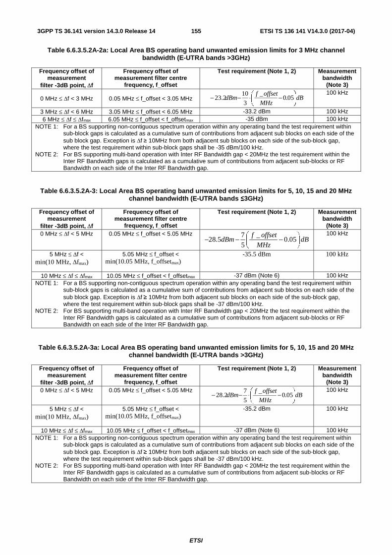
ETSI
ETSI TS 136 141 V14.3.0 (2017-04)1553GPP TS 36.141 version 14.3.0 Release 14
Table 6.6.3.5.2A-2a: Local Area BS operating band unwanted emission limits for 3 MHz channel bandwidth (E-UTRA bands >3GHz)
Frequency offset of measurement
filter -3dB point, Δf
Frequency offset of measurement filter centre
frequency, f_offset
Test requirement (Note 1, 2) Measurement bandwidth
(Note 3)
0 MHz ≤ Δf < 3 MHz 0.05 MHz ≤ f_offset < 3.05 MHz dBMHz
offsetfdBm ⎟
⎠
⎞⎜⎝
⎛ −⋅−− 05.0_
3
1023.2
100 kHz
3 MHz ≤ Δf < 6 MHz 3.05 MHz ≤ f_offset < 6.05 MHz -33.2 dBm 100 kHz 6 MHz ≤ Δf ≤ Δfmax 6.05 MHz ≤ f_offset < f_offsetmax -35 dBm 100 kHz
NOTE 1: For a BS supporting non-contiguous spectrum operation within any operating band the test requirement within sub-block gaps is calculated as a cumulative sum of contributions from adjacent sub blocks on each side of the sub block gap. Exception is Δf ≥ 10MHz from both adjacent sub blocks on each side of the sub-block gap, where the test requirement within sub-block gaps shall be -35 dBm/100 kHz.
NOTE 2: For BS supporting multi-band operation with Inter RF Bandwidth gap < 20MHz the test requirement within the Inter RF Bandwidth gaps is calculated as a cumulative sum of contributions from adjacent sub-blocks or RF Bandwidth on each side of the Inter RF Bandwidth gap.
Table 6.6.3.5.2A-3: Local Area BS operating band unwanted emission limits for 5, 10, 15 and 20 MHz channel bandwidth (E-UTRA bands ≤3GHz)
Frequency offset of measurement
filter -3dB point, Δf
Frequency offset of measurement filter centre
frequency, f_offset
Test requirement (Note 1, 2) Measurement bandwidth
(Note 3) 0 MHz ≤ Δf < 5 MHz 0.05 MHz ≤ f_offset < 5.05 MHz 7 _
28.5 0.055
f offsetdBm dB
MHz⎛ ⎞− − −⎜ ⎟⎝ ⎠
100 kHz
5 MHz ≤ Δf < min(10 MHz, Δfmax)
5.05 MHz ≤ f_offset < min(10.05 MHz, f_offsetmax)
-35.5 dBm 100 kHz
10 MHz ≤ Δf ≤ Δfmax 10.05 MHz ≤ f_offset < f_offsetmax -37 dBm (Note 6) 100 kHz NOTE 1: For a BS supporting non-contiguous spectrum operation within any operating band the test requirement within
sub-block gaps is calculated as a cumulative sum of contributions from adjacent sub blocks on each side of the sub block gap. Exception is Δf ≥ 10MHz from both adjacent sub blocks on each side of the sub-block gap, where the test requirement within sub-block gaps shall be -37 dBm/100 kHz.
NOTE 2: For BS supporting multi-band operation with Inter RF Bandwidth gap < 20MHz the test requirement within the Inter RF Bandwidth gaps is calculated as a cumulative sum of contributions from adjacent sub-blocks or RF Bandwidth on each side of the Inter RF Bandwidth gap.
Table 6.6.3.5.2A-3a: Local Area BS operating band unwanted emission limits for 5, 10, 15 and 20 MHz channel bandwidth (E-UTRA bands >3GHz)
Frequency offset of measurement
filter -3dB point, Δf
Frequency offset of measurement filter centre
frequency, f_offset
Test requirement (Note 1, 2) Measurement bandwidth
(Note 3) 0 MHz ≤ Δf < 5 MHz 0.05 MHz ≤ f_offset < 5.05 MHz
dBMHz
offsetfdBm ⎟
⎠
⎞⎜⎝
⎛ −⋅−− 05.0_
5
728.2
100 kHz
5 MHz ≤ Δf < min(10 MHz, Δfmax)
5.05 MHz ≤ f_offset < min(10.05 MHz, f_offsetmax)
-35.2 dBm 100 kHz
10 MHz ≤ Δf ≤ Δfmax 10.05 MHz ≤ f_offset < f_offsetmax -37 dBm (Note 6) 100 kHz NOTE 1: For a BS supporting non-contiguous spectrum operation within any operating band the test requirement within
sub-block gaps is calculated as a cumulative sum of contributions from adjacent sub blocks on each side of the sub block gap. Exception is Δf ≥ 10MHz from both adjacent sub blocks on each side of the sub-block gap, where the test requirement within sub-block gaps shall be -37 dBm/100 kHz.
NOTE 2: For BS supporting multi-band operation with Inter RF Bandwidth gap < 20MHz the test requirement within the Inter RF Bandwidth gaps is calculated as a cumulative sum of contributions from adjacent sub-blocks or RF Bandwidth on each side of the Inter RF Bandwidth gap.

ETSI
ETSI TS 136 141 V14.3.0 (2017-04)1563GPP TS 36.141 version 14.3.0 Release 14
6.6.3.5.2B Test requirements for Home BS (Category A and B)
For Home BS in E-UTRA bands ≤3GHz, emissions shall not exceed the maximum levels specified in Tables 6.6.3.5.2B-1, 6.6.3.5.2B-2 and 6.6.3.5.2B-3.
For Home BS in E-UTRA bands >3GHz, emissions shall not exceed the maximum levels specified in Tables 6.6.3.5.2B-1a, 6.6.3.5.2B-2a and 6.6.3.5.2B-3a.
Table 6.6.3.5.2B-1: Home BS operating band unwanted emission limits for 1.4 MHz channel bandwidth (E-UTRA bands ≤3GHz)
Frequency offset of measurement
filter -3dB point, Δf
Frequency offset of measurement filter centre
frequency, f_offset
Test requirement Measurement bandwidth
(Note 3)
0 MHz ≤ Δf < 1.4 MHz 0.05 MHz ≤ f_offset < 1.45 MHz 6 _
28.5 0.051.4
f offsetdBm dB
MHz− −⎛ ⎞+ ⎜ ⎟
⎝ ⎠
100 kHz
1.4 MHz ≤ Δf < 2.8 MHz 1.45 MHz ≤ f_offset < 2.85 MHz -34.5 dBm 100 kHz 2.8 MHz ≤ Δf ≤ Δfmax 3.3 MHz ≤ f_offset < f_offsetmax 52 , 2dBm 20dBm
50 , P<2dBm
P dB P
dBm
− ≤ ≤⎧⎨−⎩
1MHz
Table 6.6.3.5.2B-1a: Home BS operating band unwanted emission limits for 1.4 MHz channel bandwidth (E-UTRA bands >3GHz)
Frequency offset of measurement
filter -3dB point, Δf
Frequency offset of measurement filter centre
frequency, f_offset
Test requirement Measurement bandwidth
(Note 3)
0 MHz ≤ Δf < 1.4 MHz 0.05 MHz ≤ f_offset < 1.45 MHz dBMHz
offsetfdBm ⎟
⎠
⎞⎜⎝
⎛ −⋅−− 05.0_
4.1
628.2
100 kHz
1.4 MHz ≤ Δf < 2.8 MHz 1.45 MHz ≤ f_offset < 2.85 MHz -34.2 dBm 100 kHz 2.8 MHz ≤ Δf ≤ Δfmax 3.3 MHz ≤ f_offset < f_offsetmax 52 , 2dBm 20dBm
50 , P<2dBm
P dB P
dBm
− ≤ ≤⎧⎨−⎩
1MHz
Table 6.6.3.5.2B-2: Home BS operating band unwanted emission limits for 3 MHz channel bandwidth (E-UTRA bands ≤3GHz)
Frequency offset of measurement
filter -3dB point, Δf
Frequency offset of measurement filter centre
frequency, f_offset
Test requirement Measurement bandwidth
(Note 3)
0 MHz ≤ Δf < 3 MHz 0.05 MHz ≤ f_offset < 3.05 MHz _
32.5 2 0.05f offset
dBm dBMHz
− − −⎛ ⎞⎜ ⎟⎝ ⎠
100 kHz
3 MHz ≤ Δf < 6 MHz 3.05 MHz ≤ f_offset < 6.05 MHz -38.5 dBm 100 kHz 6 MHz ≤ Δf ≤ Δfmax 6.5 MHz ≤ f_offset < f_offsetmax 52 , 2dBm 20dBm
50 , P<2dBm
P dB P
dBm
− ≤ ≤⎧⎨−⎩
1MHz
Table 6.6.3.5.2B-2a: Home BS operating band unwanted emission limits for 3 MHz channel bandwidth (E-UTRA bands >3GHz)
Frequency offset of measurement
filter -3dB point, Δf
Frequency offset of measurement filter centre
frequency, f_offset
Test requirement Measurement bandwidth
(Note 3)
0 MHz ≤ Δf < 3 MHz 0.05 MHz ≤ f_offset < 3.05 MHz dBMHz
offsetfdBm ⎟
⎠
⎞⎜⎝
⎛ −⋅−− 05.0_
232.2 100 kHz
3 MHz ≤ Δf < 6 MHz 3.05 MHz ≤ f_offset < 6.05 MHz -38.2 dBm 100 kHz 6 MHz ≤ Δf ≤ Δfmax 6.5 MHz ≤ f_offset < f_offsetmax 52 , 2dBm 20dBm
50 , P<2dBm
P dB P
dBm
− ≤ ≤⎧⎨−⎩
1MHz

ETSI
ETSI TS 136 141 V14.3.0 (2017-04)1573GPP TS 36.141 version 14.3.0 Release 14
Table 6.6.3.5.2B-3: Home BS operating band unwanted emission limits for 5, 10, 15 and 20 MHz channel bandwidth (E-UTRA bands ≤3GHz)
Frequency offset of measurement
filter -3dB point, Δf
Frequency offset of measurement filter centre
frequency, f_offset
Test requirement Measurement bandwidth
(Note 3) 0 MHz ≤ Δf < 5 MHz 0.05 MHz ≤ f_offset < 5.05 MHz 6 _
34.5 0.055
f offsetdBm dB
MHz− − −⎛ ⎞
⎜ ⎟⎝ ⎠
100 kHz
5 MHz ≤ Δf < min(10 MHz, ∆fmax)
5.05 MHz ≤ f_offset < min(10.05 MHz, f_offsetmax)
-40.5 dBm 100 kHz
10 MHz ≤ Δf ≤ Δfmax 10.5 MHz ≤ f_offset < f_offsetmax 52 , 2dBm 20dBm
50 , P<2dBm
P dB P
dBm
− ≤ ≤⎧⎨−⎩
(Note 6)
1MHz
Table 6.6.3.5.2B-3a: Home BS operating band unwanted emission limits for 5, 10, 15 and 20 MHz channel bandwidth (E-UTRA bands >3GHz)
Frequency offset of measurement
filter -3dB point, Δf
Frequency offset of measurement filter centre
frequency, f_offset
Test requirement Measurement bandwidth
(Note 3) 0 MHz ≤ Δf < 5 MHz 0.05 MHz ≤ f_offset < 5.05 MHz
dBMHz
offsetfdBm ⎟
⎠
⎞⎜⎝
⎛ −⋅−− 05.0_
5
634.2
100 kHz
5 MHz ≤ Δf < min(10 MHz, ∆fmax)
5.05 MHz ≤ f_offset < min(10.05 MHz, f_offsetmax)
-40.2 dBm 100 kHz
10 MHz ≤ Δf ≤ Δfmax 10.5 MHz ≤ f_offset < f_offsetmax 52 , 2dBm 20dBm
50 , P<2dBm
P dB P
dBm
− ≤ ≤⎧⎨−⎩
(Note 6)
1MHz
6.6.3.5.2C Test requirements for Medium Range BS (Category A and B)
For Medium Range BS in E-UTRA bands ≤3GHz, emissions shall not exceed the maximum levels specified in Tables 6.6.3.5.2C-1, 6.6.3.5.2C-2, 6.6.3.5.2C-3, 6.6.3.5.2C-4, 6.6.3.5.2C-5 and 6.6.3.5.2C-6.
For Medium Range BS in E-UTRA bands >3GHz, emissions shall not exceed the maximum levels specified in Tables 6.6.3.5.2C-1a, 6.6.3.5.2C-2a, 6.6.3.5.2C-3a, 6.6.3.5.2C-4a, 6.6.3.5.2C-5a and 6.6.3.5.2C-6a.
Table 6.6.3.5.2C-1: Medium Range BS operating band unwanted emission limits for 1.4 MHz channel bandwidth, 31 < Pmax,c ≤ 38 dBm (E-UTRA bands ≤3GHz)
Frequency offset of measurement
filter -3dB point, Δf
Frequency offset of measurement filter centre
frequency, f_offset
Test requirement (Note 1, 2) Measurement bandwidth
(Note 3) 0 MHz ≤ Δf < 1.4 MHz 0.05 MHz ≤ f_offset < 1.45 MHz
dBMHz
offsetfdB ⎟
⎠
⎞⎜⎝
⎛ −−− 05.0_
4.1
105.43P c max,
100 kHz
1.4 MHz ≤ Δf < 2.8 MHz 1.45 MHz ≤ f_offset < 2.85 MHz Pmax,c-53.5dB 100 kHz 2.8 MHz ≤ Δf ≤ Δfmax 2.85 MHz ≤ f_offset < f_offsetmax -25dBm 100 kHz
NOTE 1: For a BS supporting non-contiguous spectrum operation within any operating band the test requirement within sub-block gaps is calculated as a cumulative sum of contributions from adjacent sub blocks on each side of the sub block gap. Exception is Δf ≥ 10MHz from both adjacent sub blocks on each side of the sub-block gap, where the test requirement within sub-block gaps shall be -25dBm/100kHz.
NOTE 2: For BS supporting multi-band operation with Inter RF Bandwidth gap < 20MHz the test requirement within the Inter RF Bandwidth gaps is calculated as a cumulative sum of contributions from adjacent sub-blocks or RF Bandwidth on each side of the Inter RF Bandwidth gap.

ETSI
ETSI TS 136 141 V14.3.0 (2017-04)1583GPP TS 36.141 version 14.3.0 Release 14
Table 6.6.3.5.2C-1a: Medium Range BS operating band unwanted emission limits for 1.4 MHz channel bandwidth, 31 < Pmax,c ≤ 38 dBm (E-UTRA bands >3GHz)
Frequency offset of measurement
filter -3dB point, Δf
Frequency offset of measurement filter centre
frequency, f_offset
Test requirement (Note 1, 2) Measurement bandwidth
(Note 3) 0 MHz ≤ Δf < 1.4 MHz 0.05 MHz ≤ f_offset < 1.45 MHz
dBMHz
offsetfdB ⎟
⎠
⎞⎜⎝
⎛ −−− 05.0_
4.1
102.43P c max,
100 kHz
1.4 MHz ≤ Δf < 2.8 MHz 1.45 MHz ≤ f_offset < 2.85 MHz Pmax,c-53.2dB 100 kHz 2.8 MHz ≤ Δf ≤ Δfmax 2.85 MHz ≤ f_offset < f_offsetmax -25dBm 100 kHz
NOTE 1: For a BS supporting non-contiguous spectrum operation within any operating band the test requirement within sub-block gaps is calculated as a cumulative sum of contributions from adjacent sub blocks on each side of the sub block gap. Exception is Δf ≥ 10MHz from both adjacent sub blocks on each side of the sub-block gap, where the test requirement within sub-block gaps shall be -25dBm/100kHz.
NOTE 2: For BS supporting multi-band operation with Inter RF Bandwidth gap < 20MHz the test requirement within the Inter RF Bandwidth gaps is calculated as a cumulative sum of contributions from adjacent sub-blocks or RF Bandwidth on each side of the Inter RF Bandwidth gap.
Table 6.6.3.5.2C-2: Medium Range BS operating band unwanted emission limits for 1.4 MHz channel bandwidth, Pmax,c ≤ 31 dBm (E-UTRA bands ≤3GHz)
Frequency offset of measurement
filter -3dB point, Δf
Frequency offset of measurement filter centre
frequency, f_offset
Test requirement (Note 1, 2) Measurement bandwidth
(Note 3) 0 MHz ≤ Δf < 1.4 MHz 0.05 MHz ≤ f_offset < 1.45 MHz 10 _
12.5dBm 0.051.4
f offsetdB
MHz⎛ ⎞− − −⎜ ⎟⎝ ⎠
100 kHz
1.4 MHz ≤ Δf < 2.8 MHz 1.45 MHz ≤ f_offset < 2.85 MHz -22.5 dBm 100 kHz 2.8 MHz ≤ Δf ≤ Δfmax 2.85 MHz ≤ f_offset < f_offsetmax -25dBm 100 kHz
NOTE 1: For a BS supporting non-contiguous spectrum operation within any operating band the test requirement within sub-block gaps is calculated as a cumulative sum of contributions from adjacent sub blocks on each side of the sub block gap. Exception is Δf ≥ 10MHz from both adjacent sub blocks on each side of the sub-block gap, where the test requirement within sub-block gaps shall be -25dBm/100kHz.
NOTE 2: For BS supporting multi-band operation with Inter RF Bandwidth gap < 20MHz the test requirement within the Inter RF Bandwidth gaps is calculated as a cumulative sum of contributions from adjacent sub-blocks or RF Bandwidth on each side of the Inter RF Bandwidth gap.
Table 6.6.3.5.2C-2a: Medium Range BS operating band unwanted emission limits for 1.4 MHz channel bandwidth, Pmax,c ≤ 31 dBm (E-UTRA bands >3GHz)
Frequency offset of measurement
filter -3dB point, Δf
Frequency offset of measurement filter centre
frequency, f_offset
Test requirement (Note 1, 2) Measurement bandwidth
(Note 3) 0 MHz ≤ Δf < 1.4 MHz 0.05 MHz ≤ f_offset < 1.45 MHz 10 _
12.2dBm 0.051.4
f offsetdB
MHz⎛ ⎞− − −⎜ ⎟⎝ ⎠
100 kHz
1.4 MHz ≤ Δf < 2.8 MHz 1.45 MHz ≤ f_offset < 2.85 MHz -22.2 dBm 100 kHz 2.8 MHz ≤ Δf ≤ Δfmax 2.85 MHz ≤ f_offset < f_offsetmax -25dBm 100 kHz
NOTE 1: For a BS supporting non-contiguous spectrum operation within any operating band the test requirement within sub-block gaps is calculated as a cumulative sum of contributions from adjacent sub blocks on each side of the sub block gap. Exception is Δf ≥ 10MHz from both adjacent sub blocks on each side of the sub-block gap, where the test requirement within sub-block gaps shall be -25dBm/100kHz.
NOTE 2: For BS supporting multi-band operation with Inter RF Bandwidth gap < 20MHz the test requirement within the Inter RF Bandwidth gaps is calculated as a cumulative sum of contributions from adjacent sub-blocks or RF Bandwidth on each side of the Inter RF Bandwidth gap.

ETSI
ETSI TS 136 141 V14.3.0 (2017-04)1593GPP TS 36.141 version 14.3.0 Release 14
Table 6.6.3.5.2C-3: Medium Range BS operating band unwanted emission limits for 3 MHz channel bandwidth, 31 < Pmax,c ≤ 38 dBm (E-UTRA bands ≤3GHz)
Frequency offset of measurement
filter -3dB point, Δf
Frequency offset of measurement filter centre
frequency, f_offset
Test requirement (Note 1, 2) Measurement bandwidth
(Note 3) 0 MHz ≤ Δf < 3 MHz 0.05 MHz ≤ f_offset < 3.05 MHz
dBMHz
offsetf⎟⎠
⎞⎜⎝
⎛ −− 05.0_
3
1047.5dB-P c max, 100 kHz
3 MHz ≤ Δf < 6 MHz 3.05 MHz ≤ f_offset < 6.05 MHz Pmax,c-57.5dB 100 kHz 6 MHz ≤ Δf ≤ Δfmax 6.05 MHz ≤ f_offset < f_offsetmax Min(Pmax,c-59dB, -25dBm) 100 kHz
NOTE 1: For a BS supporting non-contiguous spectrum operation within any operating band the test requirement within sub-block gaps is calculated as a cumulative sum of contributions from adjacent sub blocks on each side of the sub block gap. Exception is Δf ≥ 10MHz from both adjacent sub blocks on each side of the sub-block gap, where the test requirement within sub-block gaps shall be Min(Pmax,c-59dB, -25dBm)/100kHz.
NOTE 2: For BS supporting multi-band operation with Inter RF Bandwidth gap < 20MHz the test requirement within the Inter RF Bandwidth gaps is calculated as a cumulative sum of contributions from adjacent sub-blocks or RF Bandwidth on each side of the Inter RF Bandwidth gap.
Table 6.6.3.5.2C-3a: Medium Range BS operating band unwanted emission limits for 3 MHz channel bandwidth, 31 < Pmax,c ≤ 38 dBm (E-UTRA bands >3GHz)
Frequency offset of measurement
filter -3dB point, Δf
Frequency offset of measurement filter centre
frequency, f_offset
Test requirement (Note 1, 2) Measurement bandwidth
(Note 3) 0 MHz ≤ Δf < 3 MHz 0.05 MHz ≤ f_offset < 3.05 MHz
dBMHz
offsetf⎟⎠
⎞⎜⎝
⎛ −− 05.0_
3
1047.2dB-P c max, 100 kHz
3 MHz ≤ Δf < 6 MHz 3.05 MHz ≤ f_offset < 6.05 MHz Pmax,c-57.2dB 100 kHz 6 MHz ≤ Δf ≤ Δfmax 6.05 MHz ≤ f_offset < f_offsetmax Min(Pmax,c-59dB, -25dBm) 100 kHz
NOTE 1: For a BS supporting non-contiguous spectrum operation within any operating band the test requirement within sub-block gaps is calculated as a cumulative sum of contributions from adjacent sub blocks on each side of the sub block gap. Exception is Δf ≥ 10MHz from both adjacent sub blocks on each side of the sub-block gap, where the test requirement within sub-block gaps shall be Min(Pmax,c-59dB, -25dBm)/100kHz.
NOTE 2: For BS supporting multi-band operation with Inter RF Bandwidth gap < 20MHz the test requirement within the Inter RF Bandwidth gaps is calculated as a cumulative sum of contributions from adjacent sub-blocks or RF Bandwidth on each side of the Inter RF Bandwidth gap.
Table 6.6.3.5.2C-4: Medium Range BS operating band unwanted emission limits for 3 MHz channel bandwidth, Pmax,c ≤ 31 dBm (E-UTRA bands ≤3GHz)
Frequency offset of measurement
filter -3dB point, Δf
Frequency offset of measurement filter centre
frequency, f_offset
Test requirement (Note 1, 2) Measurement bandwidth
(Note 3) 0 MHz ≤ Δf < 3 MHz 0.05 MHz ≤ f_offset < 3.05 MHz 10 _
-16.5dBm 0.053
f offsetdB
MHz⎛ ⎞− −⎜ ⎟⎝ ⎠
100 kHz
3 MHz ≤ Δf < 6 MHz 3.05 MHz ≤ f_offset < 6.05 MHz -26.5 dBm 100 kHz 6 MHz ≤ Δf ≤ Δfmax 6.05 MHz ≤ f_offset < f_offsetmax -28 dBm 100 kHz
NOTE 1: For a BS supporting non-contiguous spectrum operation within any operating band the test requirement within sub-block gaps is calculated as a cumulative sum of contributions from adjacent sub blocks on each side of the sub block gap. Exception is Δf ≥ 10MHz from both adjacent sub blocks on each side of the sub-block gap, where the test requirement within sub-block gaps shall be -28dBm/100kHz.
NOTE 2: For BS supporting multi-band operation with Inter RF Bandwidth gap < 20MHz the test requirement within the Inter RF Bandwidth gaps is calculated as a cumulative sum of contributions from adjacent sub-blocks or RF Bandwidth on each side of the Inter RF Bandwidth gap.

ETSI
ETSI TS 136 141 V14.3.0 (2017-04)1603GPP TS 36.141 version 14.3.0 Release 14
Table 6.6.3.5.2C-4a: Medium Range BS operating band unwanted emission limits for 3 MHz channel bandwidth, Pmax,c ≤ 31 dBm (E-UTRA bands >3GHz)
Frequency offset of measurement
filter -3dB point, Δf
Frequency offset of measurement filter centre
frequency, f_offset
Test requirement (Note 1, 2) Measurement bandwidth
(Note 3) 0 MHz ≤ Δf < 3 MHz 0.05 MHz ≤ f_offset < 3.05 MHz 10 _
-16.2dBm 0.053
f offsetdB
MHz⎛ ⎞− −⎜ ⎟⎝ ⎠
100 kHz
3 MHz ≤ Δf < 6 MHz 3.05 MHz ≤ f_offset < 6.05 MHz -26.2 dBm 100 kHz 6 MHz ≤ Δf ≤ Δfmax 6.05 MHz ≤ f_offset < f_offsetmax -28 dBm 100 kHz
NOTE 1: For a BS supporting non-contiguous spectrum operation within any operating band the test requirement within sub-block gaps is calculated as a cumulative sum of contributions from adjacent sub blocks on each side of the sub block gap. Exception is Δf ≥ 10MHz from both adjacent sub blocks on each side of the sub-block gap, where the test requirement within sub-block gaps shall be -28dBm/100kHz.
NOTE 2: For BS supporting multi-band operation with Inter RF Bandwidth gap < 20MHz the test requirement within the Inter RF Bandwidth gaps is calculated as a cumulative sum of contributions from adjacent sub-blocks or RF Bandwidth on each side of the Inter RF Bandwidth gap.
Table 6.6.3.5.2C-5: Medium Range BS operating band unwanted emission limits for 5, 10, 15 and 20 MHz channel bandwidth, 31< Pmax,c ≤ 38 dBm (E-UTRA bands ≤3GHz)
Frequency offset of measurement
filter -3dB point, Δf
Frequency offset of measurement filter centre
frequency, f_offset
Test requirement (Note 1, 2) Measurement bandwidth
(Note 3) 0 MHz ≤ Δf < 5 MHz 0.05 MHz ≤ f_offset < 5.05 MHz
dBMHz
offsetf⎟⎠
⎞⎜⎝
⎛ −− 05.0_
5
751.5dB-P c max,
100 kHz
5 MHz ≤ Δf < min(10 MHz, ∆fmax)
5.05 MHz ≤ f_offset < min(10.05 MHz, f_offsetmax)
Pmax,c-58.5dB 100 kHz
10 MHz ≤ Δf ≤ Δfmax 10.05 MHz ≤ f_offset < f_offsetmax Min(Pmax,c-60dB, -25dBm) (Note 6) 100 kHz NOTE 1: For a BS supporting non-contiguous spectrum operation within any operating band the test requirement within
sub-block gaps is calculated as a cumulative sum of contributions from adjacent sub blocks on each side of the sub block gap. Exception is Δf ≥ 10MHz from both adjacent sub blocks on each side of the sub-block gap, where the test requirement within sub-block gaps shall be Min(Pmax,c-60dB, -25dBm)/100kHz.
NOTE 2: For BS supporting multi-band operation with Inter RF Bandwidth gap < 20MHz the test requirement within the Inter RF Bandwidth gaps is calculated as a cumulative sum of contributions from adjacent sub-blocks or RF Bandwidth on each side of the Inter RF Bandwidth gap.
Table 6.6.3.5.2C-5a: Medium Range BS operating band unwanted emission limits for 5, 10, 15 and 20 MHz channel bandwidth, 31< Pmax,c ≤ 38 dBm (E-UTRA bands >3GHz)
Frequency offset of measurement
filter -3dB point, Δf
Frequency offset of measurement filter centre
frequency, f_offset
Test requirement (Note 1, 2) Measurement bandwidth
(Note 3) 0 MHz ≤ Δf < 5 MHz 0.05 MHz ≤ f_offset < 5.05 MHz
dBMHz
offsetf⎟⎠
⎞⎜⎝
⎛ −− 05.0_
5
751.2dB-P c max,
100 kHz
5 MHz ≤ Δf < min(10 MHz, ∆fmax)
5.05 MHz ≤ f_offset < min(10.05 MHz, f_offsetmax)
Pmax,c-58.2dB 100 kHz
10 MHz ≤ Δf ≤ Δfmax 10.05 MHz ≤ f_offset < f_offsetmax Min(Pmax,c-60dB, -25dBm) (Note 6) 100 kHz NOTE 1: For a BS supporting non-contiguous spectrum operation within any operating band the test requirement within
sub-block gaps is calculated as a cumulative sum of contributions from adjacent sub blocks on each side of the sub block gap. Exception is Δf ≥ 10MHz from both adjacent sub blocks on each side of the sub-block gap, where the test requirement within sub-block gaps shall be Min(Pmax,c-60dB, -25dBm)/100kHz.
NOTE 2: For BS supporting multi-band operation with Inter RF Bandwidth gap < 20MHz the test requirement within the Inter RF Bandwidth gaps is calculated as a cumulative sum of contributions from adjacent sub-blocks or RF Bandwidth on each side of the Inter RF Bandwidth gap.

ETSI
ETSI TS 136 141 V14.3.0 (2017-04)1613GPP TS 36.141 version 14.3.0 Release 14
Table 6.6.3.5.2C-6: Medium Range BS operating band unwanted emission limits for 5, 10, 15 and 20 MHz channel bandwidth, Pmax,c ≤ 31 dBm (E-UTRA bands ≤3GHz)
Frequency offset of measurement
filter -3dB point, Δf
Frequency offset of measurement filter centre
frequency, f_offset
Test requirement (Note 1, 2) Measurement bandwidth
(Note 3) 0 MHz ≤ Δf < 5 MHz 0.05 MHz ≤ f_offset < 5.05 MHz 7 _
-20.5 dBm 0.055
f offsetdB
MHz⎛ ⎞− −⎜ ⎟⎝ ⎠
100 kHz
5 MHz ≤ Δf < min(10 MHz, ∆fmax)
5.05 MHz ≤ f_offset < min(10.05 MHz, f_offsetmax)
-27.5 dBm 100 kHz
10 MHz ≤ Δf ≤ Δfmax 10.05 MHz ≤ f_offset < f_offsetmax -29 dBm (Note 6) 100 kHz NOTE 1: For a BS supporting non-contiguous spectrum operation within any operating band the test requirement within
sub-block gaps is calculated as a cumulative sum of contributions from adjacent sub blocks on each side of the sub block gap. Exception is Δf ≥ 10MHz from both adjacent sub blocks on each side of the sub-block gap, where the test requirement within sub-block gaps shall be -29dBm/100kHz.
NOTE 2: For BS supporting multi-band operation with Inter RF Bandwidth gap < 20MHz the test requirement within the Inter RF Bandwidth gaps is calculated as a cumulative sum of contributions from adjacent sub-blocks or RF Bandwidth on each side of the Inter RF Bandwidth gap.
Table 6.6.3.5.2C-6a: Medium Range BS operating band unwanted emission limits for 5, 10, 15 and 20 MHz channel bandwidth, Pmax,c ≤ 31 dBm (E-UTRA bands >3GHz)
Frequency offset of measurement
filter -3dB point, Δf
Frequency offset of measurement filter centre
frequency, f_offset
Test requirement (Note 1, 2) Measurement bandwidth
(Note 3) 0 MHz ≤ Δf < 5 MHz 0.05 MHz ≤ f_offset < 5.05 MHz 7 _
-20.2 dBm 0.055
f offsetdB
MHz⎛ ⎞− −⎜ ⎟⎝ ⎠
100 kHz
5 MHz ≤ Δf < min(10 MHz, ∆fmax)
5.05 MHz ≤ f_offset < min(10.05 MHz, f_offsetmax)
-27.2 dBm 100 kHz
10 MHz ≤ Δf ≤ Δfmax 10.05 MHz ≤ f_offset < f_offsetmax -29 dBm (Note 6) 100 kHz NOTE 1: For a BS supporting non-contiguous spectrum operation within any operating band the test requirement within
sub-block gaps is calculated as a cumulative sum of contributions from adjacent sub blocks on each side of the sub block gap. Exception is Δf ≥ 10MHz from both adjacent sub blocks on each side of the sub-block gap, where the test requirement within sub-block gaps shall be -29dBm/100kHz.
NOTE 2: For BS supporting multi-band operation with Inter RF Bandwidth gap < 20MHz the test requirement within the Inter RF Bandwidth gaps is calculated as a cumulative sum of contributions from adjacent sub-blocks or RF Bandwidth on each side of the Inter RF Bandwidth gap.

ETSI
ETSI TS 136 141 V14.3.0 (2017-04)1623GPP TS 36.141 version 14.3.0 Release 14
6.6.3.5.2D Minimum requirements for Local Area and Medium Range BS in Band 46 (Category A and B)
For Local Area and Medium Range BS operating in Band 46, emissions shall not exceed the maximum levels specified in Tables 6.6.3.5.2D-1 and 6.6.3.5.2D-2.
Table 6.6.3.5.2D-1: Local Area and Medium Range BS operating band unwanted emission limits in Band 46 for 20MHz channel bandwidth
Frequency offset of measurement
filter -3dB point, Δf
Frequency offset of measurement filter centre
frequency, f_offset
Test requirement (Note 1) Measurement bandwidth
(Note 5) 0 MHz ≤ Δf < 1 MHz 0.05 MHz ≤ f_offset < 1.05 MHz _
Pmax,c 32.6 10 0.05f offset
dB dBMHz
⎛ ⎞− − −⎜ ⎟⎝ ⎠
100 kHz
1 MHz ≤ Δf < min(10 MHz, Δfmax)
1.05 MHz ≤ f_offset < min(10.05 MHz, f_offsetmax)
8 _Pmax,c 42.6 1.05
9
f offsetdB dB
MHz⎛ ⎞− − −⎜ ⎟⎝ ⎠
100 kHz
10 MHz ≤ Δf < min(20 MHz, Δfmax)
10.05 MHz ≤ f_offset < min(20.05 MHz, f_offsetmax)
12 _Pmax,c 50.6 10.05
10
f offsetdB dB
MHz⎛ ⎞− − −⎜ ⎟⎝ ⎠
100 kHz
20 MHz ≤ Δf < min(170 MHz, Δfmax)
20.05 MHz ≤ f_offset < min(170.05 MHz, f_offsetmax)
Max(Pmax,c - 62.6dB, -40dBm) 100 kHz
170 MHz ≤ Δf < min(206 MHz, Δfmax)
170.05 MHz ≤ f_offset < min(206.05 MHz, f_offsetmax)
Max(Pmax,c - 64.6dB, -40dBm) 100 kHz
206 MHz ≤ Δf ≤ Δfmax 206.05 MHz ≤ f_offset < f_offsetmax
Max(Pmax,c - 69.6dB, -40dBm) 100 kHz
NOTE 1: For a BS supporting non-contiguous spectrum operation within any operating band, the minimum requirement within sub-block gaps is calculated as a cumulative sum of contributions from adjacent sub blocks on each side of the sub block gap. Exception is Δf ≥ 20 MHz from both adjacent sub blocks on each side of the sub-block gap, where the minimum requirement within sub-block gaps shall be Max (Pmax,c - 62.6dB, -40 dBm)/100kHz.
Table 6.6.3.5.2D-2: Local Area and Medium Range BS operating band unwanted emission limits in Band 46 for 10 MHz channel bandwidth
Frequency offset of measurement
filter -3dB point, Δf
Frequency offset of measurement filter centre
frequency, f_offset
Test requirement (Note 1) Measurement bandwidth
(Note 5) 0 MHz ≤ Δf < 0.5 MHz 0.05 MHz ≤ f_offset < 0.55 MHz
dBMHz
offsetf⎟⎠
⎞⎜⎝
⎛ −− 05.0_
2027.3dB-cPmax, 100 kHz
0.5 MHz ≤ Δf < 5 MHz 0.55 MHz ≤ f_offset < min(5.05 MHz, f_offsetmax) dB
MHz
offsetf⎟⎠
⎞⎜⎝
⎛ −− 55.0_
9
1637.3dB-cPmax,
100 kHz
5 MHz ≤ Δf < min(10 MHz, Δfmax)
5.05 MHz ≤ f_offset < min(10.05 MHz, f_offsetmax) dB
MHz
offsetf⎟⎠
⎞⎜⎝
⎛ −− 05.5_
5
1245.3dB-cPmax,
100 kHz
10 MHz ≤ Δf < min(85 MHz, Δfmax)
10.05 MHz ≤ f_offset < min(85.05 MHz, f_offsetmax)
Max(Pmax,c – 57.3dB, -40dBm) 100 kHz
85 MHz ≤ Δf < min(103 MHz, Δfmax)
85.05 MHz ≤ f_offset < min(103.05 MHz, f_offsetmax)
Max(Pmax,c – 59.3dB, -40dBm) 100 kHz
103 MHz ≤ Δf ≤ Δfmax 103.05 MHz ≤ f_offset < f_offsetmax
Max(Pmax,c – 64.3dB, -40dBm) 100 kHz
NOTE 1: For a BS supporting non-contiguous spectrum operation within any operating band, the minimum requirement within sub-block gaps is calculated as a cumulative sum of contributions from adjacent sub blocks on each side of the sub block gap. Exception is Δf ≥ 10 MHz from both adjacent sub blocks on each side of the sub-block gap, where the minimum requirement within sub-block gaps shall be Max (Pmax,c – 57.3dB, -40 dBm)/100kHz.

ETSI
ETSI TS 136 141 V14.3.0 (2017-04)1633GPP TS 36.141 version 14.3.0 Release 14
6.6.3.5.2E Minimum requirements for stand-alone NB-IoT Wide Area BS
For stand-alone NB-IoT BS in E-UTRA bands ≤3GHz, emissions shall not exceed the maximum levels specified in Tables 6.6.3.5.2E-1.
Table 6.6.3.5.2E-1: Stand-alone NB-IoT BS operating band unwanted emission limits (E-UTRA bands ≤3GHz)
Frequency offset of measurement
filter -3dB point, Δf
Frequency offset of measurement filter centre
frequency, f_offset
Minimum requirement (Note 1, 2, 3, 4) Measurement bandwidth
(Note 6) 0 MHz ≤ Δf < 0.05
MHz 0.015 MHz ≤ f_offset <
0.065 MHz
)5.12
,015.0605.6(
dBm
XdBdBMHz
fdBmMax
offset
−
+⎟⎟⎠
⎞⎜⎜⎝
⎛−⋅−
30 kHz
0.05 MHz ≤ Δf < 0.15 MHz
0.065 MHz ≤ f_offset < 0.165 MHz
)5.12
,065.01605.3(
dBm
XdBdBMHz
fdBmMax
offset
−
+⎟⎟⎠
⎞⎜⎜⎝
⎛−⋅−
30 kHz
0.15 MHz ≤ Δf < 0.2 MHz
(Note 1)
0.165 MHz ≤ f_offset < 0.215 MHz
-12.5 dBm 30 kHz
0.2 MHz ≤ Δf < 1 MHz
0.215 MHz ≤ f_offset < 1.015 MHz dB
MHz
offsetfdBm ⎟
⎠
⎞⎜⎝
⎛ −⋅−− 215.0_
155.12 30 kHz
(Note 6) 1.015 MHz ≤ f_offset < 1.5 MHz
-24.5 dBm 30 kHz
1 MHz ≤ Δf ≤ min(Δfmax, 10 MHz)
1.5 MHz ≤ f_offset < min(f_offsetmax, 10.5 MHz)
-11.5 dBm 1 MHz
10 MHz ≤ Δf ≤ Δfmax 10.5 MHz ≤ f_offset < f_offsetmax
-15 dBm (Note 7) 1 MHz
NOTE 1: The limits in this table only apply for operation with a standalone NB-IoT carrier adjacent to the Base Station RF Bandwidth edge.
NOTE 2: For a BS supporting non-contiguous spectrum operation within any operating band the minimum requirement within sub-block gaps is calculated as a cumulative sum of contributions from adjacent sub blocks on each side of the sub block gap.
NOTE 3: For a BS supporting multi-band operation with Inter RF Bandwidth gap < 20MHz the minimum requirement within the Inter RF Bandwidth gaps is calculated as a cumulative sum of contributions from adjacent sub-blocks or RF Bandwidth on each side of the Inter RF Bandwidth gap.]
NOTE 4: In case the carrier adjacent to the RF bandwidth edge is a standalone NB-IoT carrier, the value of X = PNB-IoTcarrier – 43, where PNB-IoTcarrier is the power level of the standalone NB-IoT carrier adjacent to the RF bandwidth edge. In other cases, X = 0.
NOTE 5: For BS that only support E-UTRA and NB-IoT multi-carrier operation, the requirements in this table do not apply to an E-UTRA BS from Release 8, which is upgraded to support E-UTRA and NB-IoT multi-carrier operation, where the upgrade does not affect existing RF parts of the radio unit related to the requirements in this table. In this case, the requirements in subclauses 6.6.3.1 and 6.6.3.2 shall apply.

ETSI
ETSI TS 136 141 V14.3.0 (2017-04)1643GPP TS 36.141 version 14.3.0 Release 14
6.6.3.5.3 Additional requirements
In certain regions the following requirement may apply. For E-UTRA BS operating in Bands 5, 26, 27 or 28, emissions shall not exceed the maximum levels specified in Tables 6.6.3.5.3-1.
Table 6.6.3.5.3-1: Additional operating band unwanted emission limits for E-UTRA bands <1GHz
Channel bandwidth
Frequency offset of measurement
filter -3dB point, Δf
Frequency offset of measurement filter centre
frequency, f_offset
Test requirement
Measurement bandwidth
(Note 3) 200 kHz 0 MHz ≤ Δf < 1 MHz 0.005 MHz ≤ f_offset < 0.995 MHz -6 dBm 10 kHz 1.4 MHz 0 MHz ≤ Δf < 1 MHz 0.005 MHz ≤ f_offset < 0.995 MHz -14 dBm 10 kHz 3 MHz 0 MHz ≤ Δf < 1 MHz 0.015 MHz ≤ f_offset < 0.985 MHz -13 dBm 30 kHz 5 MHz 0 MHz ≤ Δf < 1 MHz 0.015 MHz ≤ f_offset < 0.985 MHz -15 dBm 30 kHz 10 MHz 0 MHz ≤ Δf < 1 MHz 0.05 MHz ≤ f_offset < 0.95 MHz -13 dBm 100 kHz 15 MHz 0 MHz ≤ Δf < 1 MHz 0.05 MHz ≤ f_offset < 0.95 MHz -13 dBm 100 kHz 20 MHz 0 MHz ≤ Δf < 1 MHz 0.05 MHz ≤ f_offset < 0.95 MHz -13 dBm 100 kHz
All 1 MHz ≤ Δf < Δfmax 1.05 MHz ≤ f_offset < f_offsetmax -13 dBm 100 kHz
In certain regions the following requirement may apply. For E-UTRA BS operating in Bands 2, 4, 10, 23, 25, 30, 35, 36, 41, 66, 70, emissions shall not exceed the maximum levels specified in Table 6.6.3.5.3-2.
Table 6.6.3.5.3-2: Additional operating band unwanted emission limits for E-UTRA bands>1GHz
Channel bandwidth
Frequency offset of measurement
filter -3dB point, Δf
Frequency offset of measurement filter centre
frequency, f_offset
Test requirement
Measurement bandwidth
(Note 3) 200 kHz 0 MHz ≤ Δf < 1 MHz 0.005 MHz ≤ f_offset < 0.995 MHz -6 dBm 10 kHz 1.4 MHz 0 MHz ≤ Δf < 1 MHz 0.005 MHz ≤ f_offset < 0.995 MHz -14 dBm 10 kHz 3 MHz 0 MHz ≤ Δf < 1 MHz 0.015 MHz ≤ f_offset < 0.985 MHz -13 dBm 30 kHz 5 MHz 0 MHz ≤ Δf < 1 MHz 0.015 MHz ≤ f_offset < 0.985 MHz -15 dBm 30 kHz 10 MHz 0 MHz ≤ Δf < 1 MHz 0.05 MHz ≤ f_offset < 0.95 MHz -13 dBm 100 kHz 15 MHz 0 MHz ≤ Δf < 1 MHz 0.05 MHz ≤ f_offset < 0.95 MHz -15 dBm 100 kHz 20 MHz 0 MHz ≤ Δf < 1 MHz 0.05 MHz ≤ f_offset < 0.95 MHz -16 dBm 100 kHz
All 1 MHz ≤ Δf < Δfmax 1.5 MHz ≤ f_offset < f_offsetmax -13 dBm 1 MHz
In certain regions the following requirement may apply. For E-UTRA BS operating in Bands 12, 13, 14, 17, 29 emissions shall not exceed the maximum levels specified in Table 6.6.3.5.3-3.
Table 6.6.3.5.3-3: Additional operating band unwanted emission limits for E-UTRA (bands 12, 13, 14, 17 and 29)
Channel bandwidth
Frequency offset of measurement
filter -3dB point, Δf
Frequency offset of measurement filter centre
frequency, f_offset
Test requirement
Measurement bandwidth
(Note 3) All 0 MHz ≤ Δf < 100 kHz 0.015 MHz ≤ f_offset < 0.085 MHz -13 dBm 30 kHz All 100 kHz ≤ Δf < Δfmax 150 kHz ≤ f_offset < f_offsetmax -13 dBm 100 kHz
In certain regions, the following requirements may apply to an E-UTRA TDD BS operating in the same geographic area and in the same operating band as another E-UTRA TDD system without synchronisation. For this case the emissions shall not exceed -52 dBm/MHz in each supported downlink operating band, except in:
- The frequency range from 10 MHz below the lower channel edge to the frequency 10 MHz above the upper channel edge of each supported band.
In certain regions the following requirement may apply for protection of DTT. For E-UTRA BS operating in Band 20, the level of emissions in the band 470-790 MHz, measured in an 8MHz filter bandwidth on centre frequencies Ffilter according to Table 6.6.3.3-4, shall not exceed the maximum emission level PEM,N declared by the manufacturer. This requirement applies in the frequency range 470-790 MHz even though part of the range falls in the spurious domain.

ETSI
ETSI TS 136 141 V14.3.0 (2017-04)1653GPP TS 36.141 version 14.3.0 Release 14
Table 6.6.3.5.3-4: Declared emissions levels for protection of DTT
Filter centre frequency, Ffilter
Measurement bandwidth
Declared emission level [dBm]
Ffilter = 8*N + 306 (MHz); 21 ≤ N ≤ 60
8 MHz PEM,N
Note: The regional requirement is defined in terms of EIRP (effective isotropic radiated power), which is dependent on both the BS emissions at the antenna connector and the deployment (including antenna gain and feeder loss). The requirement defined above provides the characteristics of the base station needed to verify compliance with the regional requirement. Compliance with the regional requirement can be determined using the method outlined in Annex G of [2].
In certain regions the following requirement may apply for the protection of systems operating in frequency bands adjacent to band 1 as defined in clause 5.5, in geographic areas in which both an adjacent band service E-UTRA are deployed.
The power of any spurious emission shall not exceed:
Table 6.6.3.5.3-5: Emissions limits for protection of adjacent band services
Operating Band
Frequency range Maximum Level Measurement Bandwidth
1 2100-2105 MHz -30 + 3.4 ⋅ (f - 2100 MHz) dBm 1 MHz 2175-2180 MHz -30 + 3.4 ⋅ (2180 MHz - f) dBm 1 MHz
In regions where FCC regulation applies, requirements for protection of GPS according to FCC Order DA 10-534 applies for operation in Band 24. The following normative requirement covers the base station, to be used together with other information about the site installation to verify compliance with the requirement in FCC Order DA 10-534. The requirement applies to BS operating in Band 24 to ensure that appropriate interference protection is provided to the 1559 – 1610 MHz band. This requirement applies to the frequency range 1559-1610 MHz, even though part of this range falls within the spurious domain.
The level of emissions in the 1559 – 1610 MHz band, measured in measurement bandwidth according to Table 6.6.3.5.3-6 shall not exceed the maximum emission levels PE_1MHz and PE_1kHz declared by the manufacturer.
Table 6.6.3.5.3-6: Declared emissions levels for protection of the 1559-1610 MHz band
Operating Band Frequency range Declared emission level [dBW]
(Measurement bandwidth = 1 MHz)
Declared emission level [dBW] of
discrete emissions of less than 700 Hz
bandwidth (Measurement
bandwidth = 1 kHz) 24 1559 - 1610 MHz PE_1MHz PE_1kHz
Note: The regional requirement in FCC Order DA 10-534 is defined in terms of EIRP (effective isotropic radiated power), which is dependent on both the BS emissions at the antenna connector and the deployment (including antenna gain and feeder loss). The EIRP level is calculated using: PEIRP = PE + Gant where PE denotes the BS unwanted emission level at the antenna connector, Gant equals the BS antenna gain minus feeder loss. The requirement defined above provides the characteristics of the base station needed to verify compliance with the regional requirement.
The following requirement may apply to E-UTRA BS operating in Band 41 in certain regions. Emissions shall not exceed the maximum levels specified in Table 6.6.3.5.3-7.

ETSI
ETSI TS 136 141 V14.3.0 (2017-04)1663GPP TS 36.141 version 14.3.0 Release 14
Table 6.6.3.5.3-7: Additional operating band unwanted emission limits for Band 41
Channel bandwidth
Frequency offset of measurement
filter -3dB point, Δf
Frequency offset of measurement filter centre
frequency, f_offset
Test requirement
Measurement bandwidth
(Note 5) 10 MHz 10 MHz ≤ Δf < 20 MHz 10.5 MHz ≤ f_offset < 19.5 MHz -22 dBm 1 MHz 20 MHz 20 MHz ≤ Δf < 40 MHz 20.5 MHz ≤ f_offset < 39.5 MHz -22 dBm 1 MHz
NOTE: This requirement applies for E-UTRA carriers allocated within 2545-2575MHz or 2595-2645MHz.
In certain regions, the following requirements may apply to E-UTRA BS operating in Band 32 within 1452-1492 MHz. The level of operating band unwanted emissions, measured on centre frequencies f_offset with filter bandwidth, according to Table 6.6.3.5.3-8, shall neither exceed the maximum emission level PEM,B32,a , PEM,B32,b nor PEM,B32,c declared by the manufacturer.
Table 6.6.3.5.3-8: Declared operating band 32 unwanted emission within 1452-1492 MHz
Frequency offset of measurement filter centre frequency, f_offset
Declared emission level [dBm]
Measurement bandwidth
2.5 MHz PEM,B32,a 5 MHz 7.5 MHz PEM,B32,b 5 MHz
12.5 MHz ≤ f_offset ≤ f_offsetmax,B32 PEM,B32,c 5 MHz NOTE: f_offsetmax,B32 denotes the frequency difference between the lower channel
edge and 1454.5 MHz, and the frequency difference between the upper channel edge and 1489.5 MHz for the set channel position.
NOTE: The regional requirement, included in [19], is defined in terms of EIRP per antenna, which is dependent on both the BS emissions at the antenna connector and the deployment (including antenna gain and feeder loss). The requirement defined above provides the characteristics of the base station needed to verify compliance with the regional requirement. The assessment of the EIRP level is described in Annex H of TS 36.104 [2].
In certain regions, the following requirement may apply to E-UTRA BS operating in Band 32 within 1452-1492 MHz for the protection of services in spectrum adjacent to the frequency range 1452-1492 MHz. The level of emissions, measured on centre frequencies Ffilter with filter bandwidth according to Table 6.6.3.5.3-9, shall neither exceed the maximum emission level PEM,B32,d nor PEM,B32,e declared by the manufacturer. This requirement applies in the frequency range 1429-1518MHz even though part of the range falls in the spurious domain.
Table 6.6.3.5.3-9: Operating band 32 declared emission outside 1452-1492 MHz
Filter centre frequency, Ffilter Declared emission level [dBm]
Measurement bandwidth
1429.5 MHz ≤ Ffilter ≤ 1448.5 MHz PEM,B32,d 1 MHz Ffilter = 1450.5 MHz PEM,B32,e 3 MHz Ffilter = 1493.5 MHz PEM,B32,e 3 MHz
1495.5 MHz ≤ Ffilter ≤ 1517.5 MHz PEM,B32,d 1 MHz
NOTE: The regional requirement, included in [19], is defined in terms of EIRP, which is dependent on both the BS emissions at the antenna connector and the deployment (including antenna gain and feeder loss). The requirement defined above provides the characteristics of the base station needed to verify compliance with the regional requirement. The assessment of the EIRP level is described in Annex H of TS 36.104 [2].
In certain regions the following requirement may apply to E-UTRA BS operating in Band 45. Emissions shall not exceed the maximum levels specified in Table 6.6.3.5.3-10.

ETSI
ETSI TS 136 141 V14.3.0 (2017-04)1673GPP TS 36.141 version 14.3.0 Release 14
Table 6.6.3.5.3-10: Emissions limits for protection of adjacent band services
Operating Band
Filter centre frequency, Ffilter Maximum Level [dBm]
Measurement Bandwidth
45 Ffilter = 1467.5 -20 1 MHz
Ffilter = 1468.5 -23 1 MHz
Ffilter = 1469.5 -26 1 MHz
Ffilter = 1470.5 -33 1 MHz
Ffilter = 1471.5 -40 1 MHz
1472.5 MHz ≤ Ffilter ≤ 1491.5 MHz -47 1 MHz
In addition for Band 46 operation, the BS may have to comply with the applicable operating band unwanted emission limits established regionally, when deployed in regions where those limits apply and under the conditions declared by the manufacturer. The regional requirements may be in the form of conducted power, power spectral density, EIRP and other types of limits. In case of regulatory limits based on EIRP, assessment of the EIRP level is described in Annex H of TS 36.104 [2].
The following requirement may apply to E-UTRA BS operating in Band 48 in certain regions. Emissions shall not exceed the maximum levels specified in Table 6.6.3.5.3-11.
Table 6.6.3.5.3-11: Additional operating band unwanted emission limits for Band 48
Channel bandwidth
Frequency offset of measurement
filter -3dB point, Δf
Frequency offset of measurement filter centre
frequency, f_offset
Minimum requirement
Measurement bandwidth
(Note 3) All 0 MHz ≤ Δf < 10 MHz 0.5 MHz ≤ f_offset < 9.5 MHz -13 dBm 1 MHz
The following notes are common to all subclauses in 6.6.3.5:
NOTE 3: As a general rule, the resolution bandwidth of the measuring equipment should be equal to the measurement bandwidth. However, to improve measurement accuracy, sensitivity and efficiency, the resolution bandwidth can be smaller than the measurement bandwidth. When the resolution bandwidth is smaller than the measurement bandwidth, the result should be integrated over the measurement bandwidth in order to obtain the equivalent noise bandwidth of the measurement bandwidth.
NOTE 4: If the above Test Requirement differs from the Minimum Requirement then the Test Tolerance applied for this test is non-zero. The Test Tolerance for this test is defined in Annex G. The explanation of how the Minimum Requirement has been relaxed by the Test Tolerance is given in Annex G.
NOTE 5: This frequency range ensures that the range of values of f_offset is continuous.
NOTE 6: The requirement is not applicable when Δfmax < 10 MHz.
NOTE 7: For Home BS, the parameter P is defined as the aggregated maximum output power of all transmit antenna connectors of Home BS.
6.6.4 Transmitter spurious emissions
6.6.4.1 Definition and applicability
Spurious emissions are emissions which are caused by unwanted transmitter effects such as harmonics emission, parasitic emission, intermodulation products and frequency conversion products, but exclude out of band emissions. This is measured at the base station antenna connector.
The transmitter spurious emission limits apply from 9 kHz to 12.75 GHz, excluding the frequency range from 10 MHz below the lowest frequency of the downlink operating band up to 10 MHz above the highest frequency of the downlink

ETSI
ETSI TS 136 141 V14.3.0 (2017-04)1683GPP TS 36.141 version 14.3.0 Release 14
operating band (see Table 5.5-1). For BS capable of multi-band operation where multiple bands are mapped on the same antenna connector, this exclusion applies for each supported operating band. For BS capable of multi-band operation where multiple bands are mapped on separate antenna connectors, the single-band requirements apply and the multi-band exclusions and provisions are not applicable.
Exceptions are the requirements in Table 6.6.4.5.4-2, Table 6.6.4.5.4-3, Table 6.6.4.5.4-4, and specifically stated exceptions in Table 6.6.4.5.4-1 and Table 6.6.4.5.4-1a that apply also closer than 10 MHz from the downlink operating band. For some operating bands the upper frequency limit is higher than 12.75 GHz.
The requirements shall apply to BS that supports E-UTRA or E-UTRA with NB-IoT in-band/guard band operation or NB-IoT standalone operation.
The requirements shall apply whatever the type of transmitter considered (single carrier, multi-carrier and/or CA) and for all transmission modes foreseen by the manufacturer's specification.
Unless otherwise stated, all requirements are measured as mean power (RMS).
6.6.4.2 Minimum Requirements
The minimum requirement is in TS 36.104 [2] subclause 6.6.4.
6.6.4.3 Test Purpose
This test measures conducted spurious emission from the E-UTRA or NB-IoT BS transmitter antenna connector, while the transmitter is in operation.
6.6.4.4 Method of Test
6.6.4.4.1 Initial conditions
Test environment: normal; see Annex D.2.
RF channels to be tested for single carrier: B, M and T; see subclause 4.7.
Base Station RF Bandwidth positions to be tested for multi-carrier and/or CA: BRFBW, MRFBW and TRFBW in single-band operation, see subclause 4.7.1; BRFBW_T’RFBW and B’RFBW_TRFBW in multi-band operation, see subclause 4.7.1.
1) Connect the BS antenna connector to a measurement receiver according to Annex I.1.1 using an attenuator or a directional coupler if necessary
2) Measurements shall use a measurement bandwidth in accordance to the conditions in TS 36.104 [2] subclause 6.6.4.
3) Detection mode: True RMS.
4) Configure the BS with transmitter(s) active.
6.6.4.4.2 Procedure
1) For a E-UTRA BS declared to be capable of single carrier operation only, set the BS to transmit a signal according to E-TM1.1 at manufacturer’s declared rated output power.
For a E-UTRA BS declared to be capable of multi-carrier and/or CA operation, set the base station to transmit according to E-TM1.1 on all carriers configured using the applicable test configuration and corresponding power setting specified in sub-clause 4.10 and 4.11.
For a E-UTRA BS declared to be capable of NB-IoT in-band operation, start transmission according to [E-TM1.1] with the NB-IoT PRB constructed according to N-TM at manufacturer’s declared rated output power.
For a E-UTRA BS declared to be capable of NB-IoT guard-band operation, start transmission according to E-TM1.1 with the NB-IoT PRB constructed according to N-TM at manufacturer’s declared rated output power.

ETSI
ETSI TS 136 141 V14.3.0 (2017-04)1693GPP TS 36.141 version 14.3.0 Release 14
For a NB-IoT BS declared to be capable of single carrier operation, start transmission according to N-TM at manufacturer’s declared rated output power.
For a NB-IoT BS declared to be capable of multi-carrier in contiguous spectrum operation in single band only, start transmission according to N-TM on all carriers configured using in the applicable test configuration and corresponding power setting specified in sub-clause 4.10 and 4.11.
For a E-UTRA and NB-IoT standalone BS declared to be capable of multi-carrier in contiguous spectrum operation in single band only, start transmission according to E-TM1.1 on all E-UTRA carriers and N-TM on all NB-IoT carriers configured using in the applicable test configuration and corresponding power setting specified in sub-clause 4.10 and 4.11.
2) Measure the emission at the specified frequencies with specified measurement bandwidth and note that the measured value does not exceed the specified value.
In addition, for a multi-band capable BS, the following step shall apply:
3) For multi-band capable BS and single band tests, repeat the steps above per involved band where single band test configurations and test models shall apply with no carrier activated in the other band. For multi-band capable BS with separate antenna connector, the antenna connector not being under test in case of single-band or multi-band test shall be terminated.
6.6.4.5 Test requirements
The measurement result in step 2 of 6.6.4.4.2 shall not exceed the maximum level specified in Table 6.6.4.5.1-1 to Table 6.6.4.5.6-1 if applicable for the BS under test.
NOTE: If a Test Requirement in this clause differs from the corresponding Minimum Requirement then the Test Tolerance applied for this test is non-zero. The Test Tolerance for this test and the explanation of how the Minimum Requirement has been relaxed by the Test Tolerance are given in Annex G.
As mandatory requirement, either subclause 6.6.4.5.1 (Category A limits) or subclause 6.6.4.5.2 (Category B limits) shall apply. The application of either Category A or Category B limits shall be the same as for Operating band unwanted emissions in subclause 6.6.3.
6.6.4.5.1 Spurious emissions (Category A)
The power of any spurious emission shall not exceed the limits in Table 6.6.4.5.1-1.
Table 6.6.4.5.1-1: BS Spurious emission limits, Category A
Frequency range Maximum level Measurement Bandwidth
Note
9kHz - 150kHz
-13 dBm
1 kHz Note 1 150kHz - 30MHz 10 kHz Note 1 30MHz - 1GHz 100 kHz Note 1
1GHz – 12.75 GHz 1 MHz Note 2 12.75 GHz – 5th harmonic
of the upper frequency edge of the DL operating
band in GHz
1 MHz Note 2, Note 3
12.75 GHz - 26 GHz 1 MHz Note 2, Note 4 NOTE 1: Bandwidth as in ITU-R SM.329 [5] , s4.1 NOTE 2: Bandwidth as in ITU-R SM.329 [5] , s4.1. Upper frequency as in ITU-R SM.329 [5] , s2.5
table 1 NOTE 3: Applies only for Bands 22, 42, 43 and 48. NOTE 4: Applies only for Band 46.

ETSI
ETSI TS 136 141 V14.3.0 (2017-04)1703GPP TS 36.141 version 14.3.0 Release 14
6.6.4.5.2 Spurious emissions (Category B)
The power of any spurious emission shall not exceed the limits in Table 6.6.4.5.2-1.
Table 6.6.4.5.2-1: BS Spurious emissions limits, Category B
Frequency range Maximum Level
Measurement Bandwidth
Note
9 kHz ↔ 150 kHz -36 dBm 1 kHz Note 1 150 kHz ↔ 30 MHz -36 dBm 10 kHz Note 1 30 MHz ↔ 1 GHz -36 dBm 100 kHz Note 1
1 GHz ↔ 12.75 GHz -30 dBm 1 MHz Note 2 12.75 GHz ↔ 5th harmonic of the upper frequency edge of the DL
operating band in GHz
-30 dBm 1 MHz Note 2, Note 3
12.75 GHz ↔ 26 GHz -30 dBm 1 MHz Note 2, Note 4 NOTE 1: Bandwidth as in ITU-R SM.329 [5] , s4.1 NOTE 2: Bandwidth as in ITU-R SM.329 [5], s4.1. Upper frequency as in ITU-R SM.329 [5] , s2.5
table 1 NOTE 3: Applies only for Bands 22, 42, 43 and 48. NOTE 4: Applies only for Band 46.
6.6.4.5.3 Protection of the BS receiver of own or different BS
This requirement shall be applied for E-UTRA FDD operation in paired operating bands in order to prevent the receivers of the BSs being desensitised by emissions from a BS transmitter. It is measured at the transmit antenna port for any type of BS which has common or separate Tx/Rx antenna ports.
The power of any spurious emission shall not exceed the limits in Table 6.6.4.5.3-1.
Table 6.6.4.5.3-1: BS Spurious emissions limits for protection of the BS receiver
Frequency range
Maximum Level
Measurement Bandwidth
Note
Wide Area BS FUL_low – FUL_high -96 dBm 100 kHz Medium Range BS FUL_low – FUL_high -91 dBm 100 kHz
Local Area BS FUL_low – FUL_high -88 dBm 100 kHz Home BS FUL_low – FUL_high -88 dBm 100 kHz
6.6.4.5.4 Co-existence with other systems in the same geographical area
6.6.4.5.4.1 Void
These requirements may be applied for the protection of system operating in frequency ranges other than the E-UTRA or NB-IoT BS operating band. The limits may apply as an optional protection of such systems that are deployed in the same geographical area as the E-UTRA BS, or they may be set by local or regional regulation as a mandatory requirement for an E-UTRA operating band. It is in some cases not stated in the present document whether a requirement is mandatory or under what exact circumstances that a limit applies, since this is set by local or regional regulation. An overview of regional requirements in the present document is given in Clause 4.3.
Some requirements may apply for the protection of specific equipment (UE, MS and/or BS) or equipment operating in specific systems (GSM, CDMA, UTRA, E-UTRA, etc.) as listed below. The power of any spurious emission shall not exceed the limits of Table 6.6.4.5.4-1 for a BS where requirements for co-existence with the system listed in the first column apply. For BS capable of multi-band operation the exclusions and conditions in the Note column of Table 6.6.4.5.4-1 apply for each supported operating band. For BS capable of multi-band operation where multiple bands are mapped on separate antenna connectors, the exclusions and conditions in the Note column of Table 6.6.4.5.4-1 apply for the operating band supported at that antenna connector.

ETSI
ETSI TS 136 141 V14.3.0 (2017-04)1713GPP TS 36.141 version 14.3.0 Release 14
Table 6.6.4.5.4-1: BS Spurious emissions limits for E-UTRA BS for co-existence with systems operating in other frequency bands

ETSI
ETSI TS 136 141 V14.3.0 (2017-04)1723GPP TS 36.141 version 14.3.0 Release 14
System type for E-UTRA to co-exist with
Frequency range for co-existence
requirement
Maximum Level
Measurement Bandwidth
Note
GSM900 921 - 960 MHz -57 dBm 100 kHz This requirement does not apply to E-UTRA BS operating in band 8
876 - 915 MHz -61 dBm 100 kHz For the frequency range 880-915 MHz, this requirement does not apply to E-UTRA BS operating in band 8, since it is already covered by the requirement in subclause 6.6.4.5.3.
DCS1800 1805 - 1880 MHz -47 dBm 100 kHz This requirement does not apply to E-UTRA BS operating in band 3.
1710 - 1785 MHz -61 dBm 100 kHz This requirement does not apply to E-UTRA BS operating in band 3, since it is already covered by the requirement in subclause 6.6.4.5.3.
PCS1900 1930 - 1990 MHz
-47 dBm 100 kHz This requirement does not apply to E-UTRA BS operating in frequency band 2, band 25, band 36 or band 70.
1850 - 1910 MHz
-61 dBm 100 kHz This requirement does not apply to E-UTRA BS operating in frequency band 2 or 25, since it is already covered by the requirement in subclause 6.6.4.5.3. This requirement does not apply to E-UTRA BS operating in frequency band 35.
GSM850 or CDMA850
869 - 894 MHz -57 dBm 100 kHz This requirement does not apply to E-UTRA BS operating in frequency band 5 or 26. This requirement applies to E-UTRA BS operating in Band 27 for the frequency range 879-894 MHz.
824 - 849 MHz -61 dBm 100 kHz This requirement does not apply to E-UTRA BS operating in frequency band 5 or 26, since it is already covered by the requirement in subclause 6.6.4.5.3. For E-UTRA BS operating in Band 27, it applies 3 MHz below the Band 27 downlink operating band.
UTRA FDD Band I or
E-UTRA Band 1
2110 - 2170 MHz -52 dBm 1 MHz This requirement does not apply to E-UTRA BS operating in band 1 or 65.
1920 - 1980 MHz
-49 dBm 1 MHz This requirement does not apply to E-UTRA BS operating in band 1 or 65, since it is already covered by the requirement in subclause 6.6.4.5.3.
UTRA FDD Band II or
E-UTRA Band 2
1930 - 1990 MHz
-52 dBm 1 MHz This requirement does not apply to E-UTRA BS operating in band 2, 25 or band 70.
1850 - 1910 MHz
-49 dBm 1 MHz This requirement does not apply to E-UTRA BS operating in band 2 or 25, since it is already covered by the requirement in subclause 6.6.4.5.3
UTRA FDD Band III or
E-UTRA Band 3
1805 - 1880 MHz
-52 dBm 1 MHz This requirement does not apply to E-UTRA BS operating in band 3.
1710 - 1785 MHz -49 dBm 1 MHz This requirement does not apply to E-UTRA BS operating in band 3 or 9, since it is already covered by the requirement in subclause 6.6.4.5.3. For E-UTRA BS operating in band 9, it applies for 1710 MHz to 1749.9 MHz and 1784.9 MHz to 1785 MHz, while the rest is covered in sub-clause 6.6.4.5.3.
UTRA FDD Band IV or
E-UTRA Band 4
2110 - 2155 MHz -52 dBm 1 MHz This requirement does not apply to E-UTRA BS operating in band 4, 10 or 66
1710 - 1755 MHz -49 dBm 1 MHz This requirement does not apply to E-UTRA BS operating in band 4, 10 or 66, since it is already covered by the requirement in subclause 6.6.4.5.3.
UTRA FDD Band V or
E-UTRA Band 5
869 - 894 MHz -52 dBm 1 MHz This requirement does not apply to E-UTRA BS operating in band 5 or 26. This requirement applies to E-UTRA BS operating in Band 27 for the frequency range 879-894 MHz.
824 - 849 MHz -49 dBm 1 MHz This requirement does not apply to E-UTRA BS operating in band 5 or 26, since it is already covered by the requirement in subclause 6.6.4.5.3. For E-UTRA BS operating in Band 27, it applies 3 MHz below the Band 27 downlink operating band.
860 - 890 MHz -52 dBm 1 MHz This requirement does not apply to E-UTRA BS operating in band 6, 18, 19.

ETSI
ETSI TS 136 141 V14.3.0 (2017-04)1733GPP TS 36.141 version 14.3.0 Release 14
UTRA FDD Band VI, XIX or E-UTRA Band
6, 18, 19
815 - 830 MHz -49 dBm 1 MHz This requirement does not apply to E-UTRA BS operating in band 18, since it is already covered by the requirement in subclause 6.6.4.5.3.
830 - 845 MHz -49 dBm 1 MHz This requirement does not apply to E-UTRA BS operating in band 6, 19, since it is already covered by the requirement in subclause 6.6.4.5.3.
UTRA FDD Band VII or
E-UTRA Band 7
2620 - 2690 MHz -52 dBm 1 MHz This requirement does not apply to E-UTRA BS operating in band 7.
2500 - 2570 MHz -49 dBm 1 MHz This requirement does not apply to E-UTRA BS operating in band 7, since it is already covered by the requirement in subclause 6.6.4.5.3.
UTRA FDD Band VIII or
E-UTRA Band 8
925 - 960 MHz -52 dBm 1 MHz This requirement does not apply to E-UTRA BS operating in band 8.
880 - 915 MHz -49 dBm 1 MHz This requirement does not apply to E-UTRA BS operating in band 8, since it is already covered by the requirement in subclause 6.6.4.5.3.
UTRA FDD Band IX or
E-UTRA Band 9
1844.9 - 1879.9 MHz
-52 dBm 1 MHz This requirement does not apply to E-UTRA BS operating in band 3 or 9.
1749.9 - 1784.9 MHz
-49 dBm 1 MHz This requirement does not apply to E-UTRA BS operating in band 3 or 9, since it is already covered by the requirement in subclause 6.6.4.5.3.
UTRA FDD Band X or
E-UTRA Band 10
2110 - 2170 MHz -52 dBm 1 MHz This requirement does not apply to E-UTRA BS operating in band 4, 10 or 66
1710 - 1770 MHz -49 dBm 1 MHz This requirement does not apply to E-UTRA BS operating in band 10 or 66, since it is already covered by the requirement in subclause 6.6.4.5.3. For E-UTRA BS operating in Band 4, it applies for 1755 MHz to 1770 MHz, while the rest is covered in sub-clause 6.6.4.5.3.
UTRA FDD Band XI or XXI E-UTRA Band
11 or 21
1475.9 - 1510.9 MHz
-52 dBm 1 MHz This requirement does not apply to E-UTRA BS operating in band 11, 21 or 32.
1427.9 - 1447.9 MHz
-49 dBm 1 MHz This requirement does not apply to E-UTRA BS operating in band 11, since it is already covered by the requirement in subclause 6.6.4.5.3. For E-UTRA BS operating in band 32, this requirement applies for carriers allocated within 1475.9MHz and 1495.9MHz.
1447.9 - 1462.9 MHz
-49 dBm 1 MHz This requirement does not apply to E-UTRA BS operating in band 21, since it is already covered by the requirement in subclause 6.6.4.5.3. For E-UTRA BS operating in band 32, this requirement applies for carriers allocated within 1475.9MHz and 1495.9MHz.
UTRA FDD Band XII or
E-UTRA Band 12
729 - 746 MHz -52 dBm 1 MHz This requirement does not apply to E-UTRA BS operating in band 12.
699 - 716 MHz -49 dBm 1 MHz This requirement does not apply to E-UTRA BS operating in band 12, since it is already covered by the requirement in subclause 6.6.4.5.3. For E-UTRA BS operating in Band 29, it applies 1 MHz below the Band 29 downlink operating band (Note 6)
UTRA FDD Band XIII or
E-UTRA Band 13
746 - 756 MHz -52 dBm 1 MHz This requirement does not apply to E-UTRA BS operating in band 13.
777 - 787 MHz -49 dBm 1 MHz This requirement does not apply to E-UTRA BS operating in band 13, since it is already covered by the requirement in subclause 6.6.4.5.3.
UTRA FDD Band XIV or
E-UTRA Band 14
758 - 768 MHz -52 dBm 1 MHz This requirement does not apply to E-UTRA BS operating in band 14.
788 - 798 MHz -49 dBm 1 MHz This requirement does not apply to E-UTRA BS operating in band 14, since it is already covered by the requirement in subclause 6.6.4.5.3.
E-UTRA Band 17
734 - 746 MHz -52 dBm 1 MHz This requirement does not apply to E-UTRA BS operating in band 17.
704 - 716 MHz -49 dBm 1 MHz This requirement does not apply to E-UTRA BS operating in band 17, since it is already covered by the requirement in subclause 6.6.4.5.3. For E-UTRA BS operating in Band 29, it applies 1 MHz below the Band 29 downlink operating band (Note 6)
791 - 821 MHz -52 dBm 1 MHz This requirement does not apply to E-UTRA BS operating in band 20 or 28.

ETSI
ETSI TS 136 141 V14.3.0 (2017-04)1743GPP TS 36.141 version 14.3.0 Release 14
UTRA FDD Band XX or
E-UTRA Band 20
832 - 862 MHz -49 dBm 1 MHz This requirement does not apply to E-UTRA BS operating in band 20, since it is already covered by the requirement in subclause 6.6.4.5.3.
UTRA FDD Band XXII or
E-UTRA Band 22
3510 – 3590 MHz -52 dBm 1 MHz This requirement does not apply to E-UTRA BS operating in band 22, 42 or 48.
3410 – 3490 MHz -49 dBm 1 MHz This requirement does not apply to E-UTRA BS operating in band 22, since it is already covered by the requirement in subclause 6.6.4.5.3. This requirement does not apply to E-UTRA BS operating in Band 42
E-UTRA Band 24
1525 – 1559 MHz -52 dBm 1 MHz This requirement does not apply to E-UTRA BS operating in band 24.
1626.5 – 1660.5 MHz
-49 dBm 1 MHz This requirement does not apply to E-UTRA BS operating in band 24, since it is already covered by the requirement in subclause 6.6.4.5.3.
UTRA FDD Band XXV or
E-UTRA Band 25
1930 - 1995 MHz -52 dBm 1 MHz This requirement does not apply to E-UTRA BS operating in band 2, 25 or 70
1850 - 1915 MHz -49 dBm 1 MHz This requirement does not apply to E-UTRA BS operating in band 25, since it is already covered by the requirement in subclause 6.6.4.5.3. For E-UTRA BS operating in Band 2, it applies for 1910 MHz to 1915 MHz, while the rest is covered in sub-clause 6.6.4.5.3.
UTRA FDD Band XXVI or E-UTRA Band
26
859 – 894 MHz -52 dBm 1 MHz This requirement does not apply to E-UTRA BS operating in band 5 or 26. This requirement applies to E-UTRA BS operating in Band 27 for the frequency range 879-894 MHz.
814 – 849 MHz -49 dBm 1 MHz This requirement does not apply to E-UTRA BS operating in band 26, since it is already covered by the requirement in subclause 6.6.4.5.3. For E-UTRA BS operating in Band 5, it applies for 814 MHz to 824 MHz, while the rest is covered in sub-clause 6.6.4. 5.3. For E-UTRA BS operating in Band 27, it applies 3 MHz below the Band 27 downlink operating band.
E-UTRA Band 27
852 – 869 MHz -52 dBm 1 MHz This requirement does not apply to E-UTRA BS operating in Band 5, 26 or 27.
807 – 824 MHz -49 dBm 1 MHz This requirement does not apply to E-UTRA BS operating in Band 27, since it is already covered by the requirement in subclause 6.6.4.5.3. For E-UTRA BS operating in Band 26, it applies for 807 MHz to 814 MHz, while the rest is covered in sub-clause 6.6.4.5.3. This requirement also applies to E-UTRA BS operating in Band 28, starting 4 MHz above the Band 28 downlink operating band (Note 5).
E-UTRA Band 28
758 - 803 MHz -52 dBm 1 MHz This requirement does not apply to E-UTRA BS operating in band 20, 28, 44, 67 or 68.
703 - 748 MHz -49 dBm 1 MHz This requirement does not apply to E-UTRA BS operating in band 28, since it is already covered by the requirement in subclause 6.6.4.5.3. This requirement does not apply to E-UTRA BS operating in Band 44. For E-UTRA BS operating in Band 67, it applies for 703 MHz to 736 MHz. For E-UTRA BS operating in Band 68, it applies for 728MHz to 733MHz.
E-UTRA Band 29
717 – 728 MHz -52 dBm 1 MHz This requirement does not apply to E-UTRA BS operating in Band 29
E-UTRA Band 30
2350 – 2360 MHz -52 dBm 1 MHz This requirement does not apply to E-UTRA BS operating in band 30 or 40.
2305 – 2315 MHz -49 dBm 1 MHz This requirement does not apply to E-UTRA BS operating in band 30, since it is already covered by the requirement in subclause 6.6.4.5.3. This requirement does not apply to E-UTRA BS operating in Band 40.
E-UTRA Band 31
462.5 -467.5 MHz -52 dBm 1 MHz This requirement does not apply to E-UTRA BS operating in band 31.
452.5 -457.5 MHz -49 dBm 1 MHz This requirement does not apply to E-UTRA BS operating in band 31, since it is already covered by the requirement in subclause 6.6.4.5.3.

ETSI
ETSI TS 136 141 V14.3.0 (2017-04)1753GPP TS 36.141 version 14.3.0 Release 14
UTRA FDD band XXXII or E-UTRA band
32
1452 – 1496 MHz -52 dBm 1 MHz This requirement does not apply to E-UTRA BS operating in band 11, 21 or 32.
UTRA TDD Band a) or E-
UTRA Band 33
1900 – 1920 MHz -52 dBm 1 MHz This requirement does not apply to E-UTRA BS operating in Band 33.
UTRA TDD Band a) or E-
UTRA Band 34
2010 – 2025 MHz -52 dBm 1 MHz This requirement does not apply to E-UTRA BS operating in Band 34.
UTRA TDD Band b) or E-
UTRA Band 35
1850 – 1910 MHz -52 dBm 1 MHz This requirement does not apply to E-UTRA BS operating in Band 35.
UTRA TDD Band b) or E-
UTRA Band 36
1930 – 1990 MHz -52 dBm 1 MHz This requirement does not apply to E-UTRA BS operating in Band 2 and 36.
UTRA TDD Band c) or E-
UTRA Band 37
1910 – 1930 MHz -52 dBm 1 MHz This is not applicable to E-UTRA BS operating in Band 37. This unpaired band is defined in ITU-R M.1036, but is pending any future deployment.
UTRA TDD Band d) or E-
UTRA Band 38
2570 – 2620 MHz -52 dBm 1 MHz This requirement does not apply to E-UTRA BS operating in Band 38 or 69.
UTRA TDD Band f) or E-
UTRA Band 39
1880 – 1920MHz -52 dBm 1 MHz This is not applicable to E-UTRA BS operating in Band 39.
UTRA TDD Band e) or E-
UTRA Band 40
2300 – 2400MHz -52 dBm 1 MHz This is not applicable to E-UTRA BS operating in Band 30 or 40.
E-UTRA Band 41
2496 – 2690 MHz -52 dBm 1 MHz This is not applicable to E-UTRA BS operating in Band 41.
E-UTRA Band 42
3400 – 3600 MHz -52 dBm 1 MHz This is not applicable to E-UTRA BS operating in Band 22, 42, 43 or 48.
E-UTRA Band 43
3600 – 3800 MHz -52 dBm 1 MHz This is not applicable to E-UTRA BS operating in Band 42, 43 or 48.
E-UTRA Band 44
703 - 803 MHz -52 dBm 1 MHz This is not applicable to E-UTRA BS operating in Band 28 or 44
E-UTRA Band 45
1447 – 1467 MHz -52 dBm 1 MHz This is not applicable to E-UTRA BS operating in Band 45
E-UTRA Band 46
5150 - 5925 MHz -52 dBm 1 MHz This is not applicable to E-UTRA BS operating in Band 46.
E-UTRA Band 48
3550 - 3700 MHz -52 dBm 1 MHz This is not applicable to E-UTRA BS operating in Band 22, 42, 43 or 48.
E-UTRA Band 65
2110 - 2200 MHz -52 dBm 1 MHz This requirement does not apply to E-UTRA BS operating in band 1 or 65,
1920 - 2010 MHz -49 dBm 1 MHz This requirement does not apply to E-UTRA BS operating in band 65, since it is already covered by the requirement in sub-clause 6.6.4.5.3. For E-UTRA BS operating in Band 1, it applies for 1980 MHz to 2010 MHz, while the rest is covered in sub-clause 6.6.4.5.3.
E-UTRA Band 66
2110 - 2200 MHz -52 dBm 1 MHz This requirement does not apply to E-UTRA BS operating in band 4, 10, 23 or 66.
1710 - 1780 MHz -49 dBm 1 MHz This requirement does not apply to E-UTRA BS operating in band 66, since it is already covered by the requirement in sub-clause 6.6.4.5.3. For E-UTRA BS operating in Band 4, it applies for 1755 MHz to 1780 MHz, while the rest is covered in sub-clause 6.6.4.5.3. For E-UTRA BS operating in Band 10, it applies for 1770 MHz to 1780 MHz, while the rest is covered in sub-clause 6.6.4.5.3.
E-UTRA Band 67
738 - 758 MHz -52 dBm 1 MHz This requirement does not apply to E-UTRA BS operating in Band 28 or 67.
E-UTRA Band 68
753 -783 MHz -52 dBm 1 MHz This requirement does not apply to E-UTRA BS operating in band 28, or 68.

ETSI
ETSI TS 136 141 V14.3.0 (2017-04)1763GPP TS 36.141 version 14.3.0 Release 14
698-728 MHz -49 dBm 1 MHz This requirement does not apply to E-UTRA BS operating in band 68, since it is already covered by the requirement in sub-clause 6.6.4.5.3. For E-UTRA BS operating in Band 28, it applies between 698 MHz and 703 MHz, while the rest is covered in sub-clause 6.6.4.5.3.
E-UTRA Band 69
2570 - 2620 MHz -52 dBm 1 MHz This requirement does not apply to E-UTRA BS operating in Band 38 or 69.
E-UTRA Band 70
1995 - 2020 MHz -52 dBm 1 MHz This requirement does not apply to E-UTRA BS operating in band 2, 25 or 70
1695 – 1710 MHz -49 dBm 1 MHz This requirement does not apply to E-UTRA BS operating in band 70, since it is already covered by the requirement in sub-clause 6.6.4.5.3.
Additional co-existence requirements in Table 6.6.4.5.4-1-1a may apply for some regions.
Table 6.6.4.5.4-1a: BS Spurious emissions limits for E-UTRA BS for co-existence with systems operating in Band 46
System type for E-UTRA to co-exist with
Frequency range for co-existence
requirement
Maximum Level
Measurement Bandwidth
Note
E-UTRA Band 46a
5150 - 5250 MHz -40 dBm 1 MHz This is only applicable to E-UTRA BS operating in Band 46c or 46d.
E-UTRA Band 46b
5250 - 5350 MHz -40 dBm 1 MHz This is only applicable to E-UTRA BS operating in Band 46c or 46d.
E-UTRA Band 46c
5470 - 5725 MHz -40 dBm 1 MHz This is only applicable to E-UTRA BS operating in Band 46a or 46b.
E-UTRA Band 46d
5725 - 5925 MHz -40 dBm 1 MHz This is only applicable to E-UTRA BS operating in Band 46a or 46b.
NOTE 1: This requirement may apply to E-UTRA BS operating in certain regions.
NOTE 1: As defined in the scope for spurious emissions in this clause, except for the cases where the noted requirements apply to a BS operating in Band 25, Band 27, Band 28 or Band 29, the co-existence requirements in Table 6.6.4.5.4-1 do not apply for the 10 MHz frequency range immediately outside the downlink operating band (see Table 5.5-1). Emission limits for this excluded frequency range may be covered by local or regional requirements.
NOTE 2: Table 6.6.4.5.4-1 assumes that two operating bands, where the frequency ranges in Table 5.5-1 would be overlapping, are not deployed in the same geographical area. For such a case of operation with overlapping frequency arrangements in the same geographical area, special co-existence requirements may apply that are not covered by the 3GPP specifications.
NOTE 3: TDD base stations deployed in the same geographical area, that are synchronized and use the same or adjacent operating bands can transmit without additional co-existence requirements. For unsynchronized base stations (except in Band 46), special co-existence requirements may apply that are not covered by the 3GPP specifications.
NOTE 5: For E-UTRA Band 28 BS, specific solutions may be required to fulfil the spurious emissions limits for E-UTRA BS for co-existence with E-UTRA Band 27 UL operating band.
NOTE 6: For E-UTRA Band 29 BS, specific solutions may be required to fulfil the spurious emissions limits for E-UTRA BS for co-existence with UTRA Band XII or E-UTRA Band 12 UL operating band or E-UTRA Band 17 UL operating band.
The power of any spurious emission shall not exceed the limits of Table 6.6.4.5.4-1a for a Home BS where requirements for co-existence with a Home BS type listed in the first column apply.

ETSI
ETSI TS 136 141 V14.3.0 (2017-04)1773GPP TS 36.141 version 14.3.0 Release 14
Table 6.6.4.5.4-1a: Home BS Spurious emissions limits for co-existence with Home BS operating in other frequency bands

ETSI
ETSI TS 136 141 V14.3.0 (2017-04)1783GPP TS 36.141 version 14.3.0 Release 14
Type of coexistence BS Frequency range for co-
location requirement
Maximum Level
Measurement Bandwidth
Note
UTRA FDD Band I or E-UTRA Band 1
1920 - 1980 MHz
-71 dBm 100 kHz This requirement does not apply to Home BS operating in band 1 or 65, since it is already covered by the requirement in subclause 6.6.4.5.3.
UTRA FDD Band II or E-UTRA Band 2
1850 - 1910 MHz
-71 dBm 100 kHz This requirement does not apply to Home BS operating in band 2 or 25, since it is already covered by the requirement in subclause 6.6.4.5.3.
UTRA FDD Band III or E-UTRA Band 3
1710 - 1785 MHz
-71 dBm 100 kHz This requirement does not apply to Home BS operating in band 3, since it is already covered by the requirement in subclause 6.6.4.5.3. For Home BS operating in band 9, it applies for 1710 MHz to 1749.9 MHz and 1784.9 MHz to 1785 MHz, while the rest is covered in sub-clause 6.6.4.5.3.
UTRA FDD Band IV or E-UTRA Band 4
1710 - 1755 MHz
-71 dBm 100 kHz This requirement does not apply to Home BS operating in band 4, 10 or 66, since it is already covered by the requirement in subclause 6.6.4.5.3.
UTRA FDD Band V or E-UTRA Band 5
824 - 849 MHz -71 dBm 100 kHz This requirement does not apply to Home BS operating in band 5 or 26, since it is already covered by the requirement in subclause 6.6.4.5.3.
UTRA FDD Band VI, XIX or E-UTRA Band 6, 18, 19
815 - 830 MHz -71 dBm 100 kHz This requirement does not apply to Home BS operating in band 18, since it is already covered by the requirement in subclause 6.6.4.5.3.
830 - 845 MHz -71 dBm 100 kHz This requirement does not apply to Home BS operating in band 6, 19, since it is already covered by the requirement in subclause 6.6.4.5.3.
UTRA FDD Band VII or E-UTRA Band 7
2500 - 2570 MHz
-71 dBm 100 kHz This requirement does not apply to Home BS operating in band 7, since it is already covered by the requirement in subclause 6.6.4.5.3.
UTRA FDD Band VIII or E-UTRA Band 8
880 - 915 MHz -71 dBm 100 kHz This requirement does not apply to Home BS operating in band 8, since it is already covered by the requirement in subclause 6.6.4.5.3.
UTRA FDD Band IX or E-UTRA Band 9
1749.9 - 1784.9 MHz
-71 dBm 100 kHz This requirement does not apply to Home BS operating in band 3 or 9, since it is already covered by the requirement in subclause 6.6.4.5.3.
UTRA FDD Band X or E-UTRA Band 10
1710 - 1770 MHz
-71 dBm 100 kHz This requirement does not apply to Home BS operating in band 10 or 66, since it is already covered by the requirement in subclause 6.6.4.5.3. For Home BS operating in Band 4, it applies for 1755 MHz to 1770 MHz, while the rest is covered in sub-clause 6.6.4.5.3.
UTRA FDD Band XI, XXI or E-UTRA Band 11, 21
1427.9 - 1447.9 MHz
-71 dBm 100 kHz This requirement does not apply to Home BS operating in band 11, since it is already covered by the requirement in subclause 6.6.4.5.3. For Home BS operating in band 32, this requirement applies for carriers allocated within 1475.9MHz and 1495.9MHz.

ETSI
ETSI TS 136 141 V14.3.0 (2017-04)1793GPP TS 36.141 version 14.3.0 Release 14
1447.9 - 1462.9 MHz
-71 dBm 100 kHz This requirement does not apply to Home BS operating in band 21, since it is already covered by the requirement in subclause 6.6.4.5.3. For Home BS operating in band 32, this requirement applies for carriers allocated within 1475.9MHz and 1495.9MHz.
UTRA FDD Band XII or E-UTRA Band 12
699 - 716 MHz -71 dBm 100 kHz This requirement does not apply to Home BS operating in band 12, since it is already covered by the requirement in subclause 6.6.4.5.3. For Home BS operating in Band 29, it applies 1 MHz below the Band 29 downlink operating band (Note 5)
UTRA FDD Band XIII or E-UTRA Band 13
777 - 787 MHz -71 dBm 100 kHz This requirement does not apply to Home BS operating in band 13, since it is already covered by the requirement in subclause 6.6.4.5.3.
UTRA FDD Band XIV or E-UTRA Band 14
788 - 798 MHz -71 dBm 100 kHz This requirement does not apply to Home BS operating in band 14, since it is already covered by the requirement in subclause 6.6.4.5.3.
E-UTRA Band 17 704 - 716 MHz -71 dBm 100 kHz This requirement does not apply to Home BS operating in band 17, since it is already covered by the requirement in subclause 6.6.4.5.3. For Home BS operating in Band 29, it applies 1 MHz below the Band 29 downlink operating band (Note 5)
UTRA FDD Band XX or E-UTRA Band 20
832 - 862 MHz -71 dBm 100 kHz This requirement does not apply to Home BS operating in band 20, since it is already covered by the requirement in subclause 6.6.4.5.3.
UTRA FDD Band XXII or E-UTRA Band 22
3410 - 3490 MHz
-71 dBm 100 kHz This requirement does not apply to Home BS operating in band 22, since it is already covered by the requirement in sub-clause 6.6.5.3. This requirement does not apply to Home BS operating in Band 42
E-UTRA Band 24 1626.5 – 1660.5 MHz
-71 dBm 100 kHz This requirement does not apply to Home BS operating in band 24, since it is already covered by the requirement in sub-clause 6.6.4.5.3.
UTRA FDD Band XXV or E-UTRA Band 25
1850 - 1915 MHz
-71 dBm 100 kHz This requirement does not apply to Home BS operating in band 25, since it is already covered by the requirement in sub-clause 6.6.4.5.3.
UTRA FDD Band XXVI or E-UTRA Band 26
814 - 849 MHz -71 dBm 100 kHz This requirement does not apply to Home BS operating in band 26, since it is already covered by the requirement in sub-clause 6.6.4.5.3. For Home BS operating in Band 5, it applies for 814 MHz to 824 MHz, while the rest is covered in sub-clause 6.6.4.5.3.
E-UTRA Band 27 807 - 824 MHz -71 dBm 100 kHz This requirement does not apply to Home BS operating in band 27, since it is already covered by the requirement in sub-clause 6.6.4.5.3. For Home BS operating in Band 26, it applies for 807 MHz to 814 MHz, while the rest is covered in sub-clause 6.6.4.5.3. This requirement also applies to E-UTRA BS operating in Band 28, starting 4 MHz above the Band 28 downlink operating band (Note 4).

ETSI
ETSI TS 136 141 V14.3.0 (2017-04)1803GPP TS 36.141 version 14.3.0 Release 14
E-UTRA Band 28 703 – 748 MHz -71 dBm 100 kHz This requirement does not apply to Home BS operating in band 28, since it is already covered by the requirement in sub-clause 6.6.4.5.3. This requirement does not apply to Home BS operating in Band 44. For E-UTRA BS operating in Band 67, it applies for 703 MHz to 736 MHz. For E-UTRA BS operating in Band 68, it applies for 728MHz to 733MHz.
E-UTRA Band 30 2305 – 2315 MHz
-71 dBm 100 kHz This requirement does not apply to Home BS operating in band 30, since it is already covered by the requirement in sub-clause 6.6.4.5.3. This requirement does not apply to Home BS operating in Band 40.
UTRA TDD Band a) or E-UTRA Band 33
1900 - 1920 MHz
-71 dBm 100 kHz This requirement does not apply to Home BS operating in Band 33.
UTRA TDD Band a) or E-UTRA Band 34
2010 - 2025 MHz
-71 dBm 100 kHz This requirement does not apply to Home BS operating in Band 34.
UTRA TDD Band b) or E-UTRA Band 35
1850 - 1910 MHz
-71 dBm 100 kHz This requirement does not apply to Home BS operating in Band 35.
UTRA TDD Band b) or E-UTRA Band 36
1930 - 1990 MHz
-71 dBm 100 kHz This requirement does not apply to Home BS operating in Band 2 and 36.
UTRA TDD Band c) or E-UTRA Band 37
1910 - 1930 MHz
-71 dBm 100 kHz This requirement does not apply to Home BS operating in Band 37. This unpaired band is defined in ITU-R M.1036, but is pending any future deployment.
UTRA TDD Band d) or E-UTRA Band 38
2570 - 2620 MHz
-71 dBm 100 kHz This requirement does not apply to Home BS operating in Band 38.
UTRA TDD Band f) or E-UTRA Band 39
1880 - 1920MHz -71 dBm 100 kHz This is not applicable to Home BS operating in Band 39.
UTRA TDD Band e) or E-UTRA Band 40
2300 - 2400MHz -71 dBm 100 kHz This is not applicable to Home BS operating in Band 30 or 40.
E-UTRA Band 41 2496 – 2690 MHz
-71 dBm 100 kHz This is not applicable to Home BS operating in Band 41.
E-UTRA Band 42 3400 - 3600 MHz
-71 dBm 100 kHz This is not applicable to Home BS operating in Band 22, 42, 43 or 48
E-UTRA Band 43 3600 - 3800 MHz
-71 dBm 100 kHz This is not applicable to Home BS operating in Band 42, 43 or 48
E-UTRA Band 44 703 - 803 MHz -71 dBm 100 kHz This is not applicable to Home BS operating in Band 28 or 44
E-UTRA Band 48 3550 - 3700 MHz
-71 dBm 100 kHz This is not applicable to Home BS operating in Band 22, 42, 43 or 48.
E-UTRA Band 65 1920 - 2010 MHz
-71 dBm 100 kHz This requirement does not apply to Home BS operating in band 65, since it is already covered by the requirement in sub-clause 6.6.4.5.3. For Home BS operating in Band 1, it applies for 1980 MHz to 2010 MHz, while the rest is covered in sub-clause 6.6.4.5.3.
E-UTRA Band 66 1710 - 1780 MHz
-71 dBm 100 kHz This requirement does not apply to Home BS operating in band 66, since it is already covered by the requirement in sub-clause 6.6.4.5.3. For Home BS operating in Band 4, it applies for 1755 MHz to 1780 MHz, while the rest is covered in sub-clause 6.6.4.5.3. For Home BS operating in Band 10, it applies for 1770 MHz to 1780 MHz, while the rest is covered in sub-clause 6.6.4.5.3.

ETSI
ETSI TS 136 141 V14.3.0 (2017-04)1813GPP TS 36.141 version 14.3.0 Release 14
E-UTRA Band 68 698-728 MHz -71 dBm 100 kHz This requirement does not apply to Home BS operating in band 68, since it is already covered by the requirement in sub-clause 6.6.4.5.3. For Home BS operating in Band 28, it applies between 698 MHz and 703 MHz, while the rest is covered in sub-clause 6.6.4.5.3.
E-UTRA Band 70 1695-1710 MHz -71 dBm 100 kHz This requirement does not apply to Home BS operating in band 70, since it is already covered by the requirement in sub-clause 6.6.4.5.3.
NOTE 1: As defined in the scope for spurious emissions in this clause, except for the cases where the noted requirements apply to a BS operating in Band 27, Band 28 or Band 29, the coexistence requirements in Table 6.6.4.5.4-1a do not apply for the 10 MHz frequency range immediately outside the Home BS transmit frequency range of a downlink operating band (see Table 5.5-1). Emission limits for this excluded frequency range may be covered by local or regional requirements.
NOTE 2: Table 6.6.4.5.4-1a assumes that two operating bands, where the frequency ranges in Table 5.5-1 would be overlapping, are not deployed in the same geographical area. For such a case of operation with overlapping frequency arrangements in the same geographical area, special co-existence requirements may apply that are not covered by the 3GPP specifications.
NOTE 3: TDD base stations deployed in the same geographical area, that are synchronized and use the same or adjacent operating bands can transmit without additional co-existence requirements. For unsynchronized base stations, special co-existence requirements may apply that are not covered by the 3GPP specifications.
NOTE 4: For E-UTRA Band 28 BS, specific solutions may be required to fulfil the spurious emissions limits for E-UTRA BS for co-existence with E-UTRA Band 27 UL operating band. NOTE 5: For E-UTRA Band 29 BS, specific solutions may be required to fulfil the spurious emissions limits for E-UTRA BS for co-existence with UTRA Band XII or E-UTRA Band 12 UL operating band or E-UTRA Band 17 UL operating band.
The following requirement may be applied for the protection of PHS. This requirement is also applicable at specified frequencies falling between 10 MHz below the lowest BS transmitter frequency of the downlink operating band and 10 MHz above the highest BS transmitter frequency of the downlink operating band (see Table 5.5-1).
The power of any spurious emission shall not exceed:
Table 6.6.4.5.4-2: E-UTRA BS Spurious emissions limits for BS for co-existence with PHS
Frequency range Maximum Level
Measurement Bandwidth
Note
1884.5 - 1915.7 MHz -41 dBm 300 kHz Applicable when co-existence with PHS system operating in 1884.5 -1915.7MHz
The following requirement shall be applied to BS operating in Bands 13 and 14 to ensure that appropriate interference protection is provided to 700 MHz public safety operations. This requirement is also applicable at the frequency range from 10 MHz below the lowest frequency of the BS transmitter operating band up to 10 MHz above the highest frequency of the BS transmitter operating band. The power of any spurious emission shall not exceed:
Table 6.6.4.5.4-3: BS Spurious emissions limits for protection of 700 MHz public safety operations
Operating Band Band Maximum Level
Measurement Bandwidth
Note
13 763 - 775 MHz -46 dBm 6.25 kHz 13 793 - 805 MHz -46 dBm 6.25 kHz 14 769 - 775 MHz -46 dBm 6.25 kHz 14 799 - 805 MHz -46 dBm 6.25 kHz

ETSI
ETSI TS 136 141 V14.3.0 (2017-04)1823GPP TS 36.141 version 14.3.0 Release 14
Table 6.6.4.5.4-4: Void
The following requirement shall be applied to BS operating in Band 26 to ensure that appropriate interference protection is provided to 800 MHz public safety operations. This requirement is also applicable at the frequency range from 10 MHz below the lowest frequency of the BS downlink operating band up to 10 MHz above the highest frequency of the BS downlink operating band.
The power of any spurious emission shall not exceed:
Table 6.6.4.5.4-5: BS Spurious emissions limits for protection of 800 MHz public safety operations
Operating Band Frequency range Maximum Level
Measurement Bandwidth
Note
26 851 - 859 MHz -13 dBm 100 kHz Applicable for offsets > 37.5kHz from the
channel edge
The following requirement may apply to E-UTRA BS operating in Band 41 in certain regions. This requirement is also applicable at the frequency range from 10 MHz below the lowest frequency of the BS downlink operating band up to 10 MHz above the highest frequency of the BS downlink operating band.
The power of any spurious emission shall not exceed:
Table 6.6.4.5.4-6: Additional E-UTRA BS Spurious emissions limits for Band 41
Frequency range Maximum Level
Measurement Bandwidth
Note
2505MHz – 2535MHz -42dBm 1 MHz 2535MHz – 2655MHz -22dBm 1 MHz Applicable at offsets
≥ 250% of channel bandwidth from carrier frequency
NOTE: This requirement applies for 10 or 20 MHz E-UTRA carriers allocated within 2545-2575MHz or 2595-2645MHz.
The following requirement may apply to E-UTRA BS operating in Band 30 in certain regions. This requirement is also applicable at the frequency range from 10 MHz below the lowest frequency of the BS downlink operating band up to 10 MHz above the highest frequency of the BS downlink operating band.
The power of any spurious emission shall not exceed:
Table 6.6.4.5.4-7: Additional E-UTRA BS Spurious emissions limits for Band 30
Frequency range Maximum Level
Measurement Bandwidth
Note
2200MHz – 2345MHz -45dBm 1 MHz 2362.5MHz – 2365MHz -25dBm 1 MHz 2365MHz – 2367.5MHz -40dBm 1 MHz 2367.5MHz – 2370MHz -42dBm 1 MHz 2370MHz – 2395MHz -45dBm 1 MHz
In addition for Band 46 operation, the BS may have to comply with the applicable spurious emission limits established regionally, when deployed in regions where those limits apply and under the conditions declared by the manufacturer. The regional requirements may be in the form of conducted power, power spectral density, EIRP and other types of limits. In case of regulatory limits based on EIRP, assessment of the EIRP level is described in Annex H of TS 36.104 [2].
The following requirement may apply to E-UTRA BS operating in Band 48 in certain regions. The power of any spurious emission shall not exceed:

ETSI
ETSI TS 136 141 V14.3.0 (2017-04)1833GPP TS 36.141 version 14.3.0 Release 14
Table 6.6.4.5.4-8: Additional E-UTRA BS Spurious emissions limits for Band 48
Frequency range Maximum Level
Measurement Bandwidth
Note
3530MHz – 3720MHz -25dBm 1 MHz Applicable 10MHz from the assigned channel edge
3100MHz – 3530MHz 3720MHz – 4200MHz
-40dBm 1 MHz
6.6.4.5.5 Co-location with other base stations
These requirements may be applied for the protection of other BS receivers when GSM900, DCS1800, PCS1900, GSM850, CDMA850, UTRA FDD, UTRA TDD and/or E-UTRA BS are co-located with an E-UTRA or NB-IoT BS.
The requirements assume a 30 dB coupling loss between transmitter and receiver and are based on co-location with base stations of the same class.
The power of any spurious emission shall not exceed the limits of Table 6.6.4.5.5-1 for a Wide Area BS where requirements for co-location with a BS type listed in the first column apply. For BS capable of multi-band operation, the exclusions and conditions in the Note column of Table 6.6.4.5.5-1 apply for each supported operating band. For BS

ETSI
ETSI TS 136 141 V14.3.0 (2017-04)1843GPP TS 36.141 version 14.3.0 Release 14
capable of multi-band operation where multiple bands are mapped on separate antenna connectors, the exclusions and conditions in the Note column of Table 6.6.4.5.5-1 apply for the operating band supported at that antenna connector.
Table 6.6.4.5.5-1: BS Spurious emissions limits for Wide Area BS co-located with another BS

ETSI
ETSI TS 136 141 V14.3.0 (2017-04)1853GPP TS 36.141 version 14.3.0 Release 14
Type of co-located BS Frequency range for co-location requirement
Maximum Level
Measurement Bandwidth
Note
Macro GSM900 876-915 MHz -98 dBm 100 kHz Macro DCS1800 1710 - 1785 MHz -98 dBm 100 kHz Macro PCS1900 1850 - 1910 MHz -98 dBm 100 kHz
Macro GSM850 or CDMA850
824 - 849 MHz -98 dBm 100 kHz
WA UTRA FDD Band I or E-UTRA Band 1
1920 - 1980 MHz
-96 dBm 100 kHz
WA UTRA FDD Band II or E-UTRA Band 2
1850 - 1910 MHz
-96 dBm 100 kHz
WA UTRA FDD Band III or E-UTRA Band 3
1710 - 1785 MHz -96 dBm 100 kHz
WA UTRA FDD Band IV or E-UTRA Band 4
1710 - 1755 MHz -96 dBm 100 kHz
WA UTRA FDD Band V or E-UTRA Band 5
824 - 849 MHz -96 dBm 100 kHz
WA UTRA FDD Band VI, XIX or
E-UTRA Band 6, 19
830 - 845 MHz -96 dBm 100 kHz
WA UTRA FDD Band VII or E-UTRA Band 7
2500 - 2570 MHz -96 dBm 100 kHz
WA UTRA FDD Band VIII or E-UTRA Band 8
880 - 915 MHz -96 dBm 100 kHz
WA UTRA FDD Band IX or E-UTRA Band 9
1749.9 - 1784.9 MHz -96 dBm 100 kHz
WA UTRA FDD Band X or E-UTRA Band 10
1710 - 1770 MHz -96 dBm 100 kHz
WA UTRA FDD Band XI or E-UTRA Band 11
1427.9 –1447.9 MHz -96 dBm 100 kHz
WA UTRA FDD Band XII or
E-UTRA Band 12
699 - 716 MHz -96 dBm 100 kHz
WA UTRA FDD Band XIII or
E-UTRA Band 13
777 - 787 MHz -96 dBm 100 kHz
WA UTRA FDD Band XIV or
E-UTRA Band 14
788 - 798 MHz -96 dBm 100 kHz
WA E-UTRA Band 17 704 - 716 MHz -96 dBm 100 kHz WA E-UTRA Band 18 815 - 830 MHz -96 dBm 100 kHz
WA UTRA FDD Band XX E-UTRA Band 20
832 - 862 MHz -96 dBm 100 kHz
WA E-UTRA Band 24 1626.5 – 1660.5 MHz -96 dBm 100 kHz WA UTRA FDD Band XXI
or E-UTRA Band 21
1447.9 – 1462.9 MHz -96 dBm 100 kHz
WA UTRA FDD Band XXII or E-UTRA Band 22
3410 – 3490 MHz -96 dBm 100 kHz This is not applicable to E-
UTRA BS operating in Band 42
WA E-UTRA Band 23 2000 - 2020 MHz -96 dBm 100 kHz WA UTRA FDD Band
XXVI or E-UTRA Band 26
814 – 849 MHz -96 dBm 100 kHz
WA E-UTRA Band 27 807 - 824 MHz -96 dBm 100 kHz WA E-UTRA Band 28 703 – 748 MHz -96 dBm 100 kHz This is not
applicable to E-UTRA BS operating
in Band 44 WA E-UTRA Band 30 2305 – 2315 MHz -96 dBm 100 kHz This is not
applicable to E-UTRA BS operating
in Band 40
WA E-UTRA Band 31 452.5 – 457.5 MHz -96 dBm 100 kHz

ETSI
ETSI TS 136 141 V14.3.0 (2017-04)1863GPP TS 36.141 version 14.3.0 Release 14
WA UTRA TDD Band a) or E-UTRA Band 33
1900 - 1920 MHz
-96 dBm 100 kHz This is not applicable to E-
UTRA BS operating in Band 33
WA UTRA TDD Band a) or E-UTRA Band 34
2010 - 2025 MHz -96 dBm 100 kHz This is not applicable to E-
UTRA BS operating in Band 34
WA UTRA TDD Band b) or E-UTRA Band 35
1850 – 1910 MHz
-96 dBm 100 kHz This is not applicable to E-
UTRA BS operating in Band 35
WA UTRA TDD Band b) or E-UTRA Band 36
1930 - 1990 MHz -96 dBm 100 kHz This is not applicable to E-
UTRA BS operating in Band 2 and 36
WA UTRA TDD Band c) or E-UTRA Band 37
1910 - 1930 MHz -96 dBm 100 kHz This is not applicable to E-
UTRA BS operating in Band 37. This unpaired band is defined in ITU-R M.1036, but is
pending any future deployment.
WA UTRA TDD Band d) or E-UTRA Band 38
2570 – 2620 MHz -96 dBm 100 kHz This is not applicable to E-
UTRA BS operating in Band 38.
WA UTRA TDD Band f) or E-UTRA Band 39
1880 – 1920MHz -96 dBm 100 kHz This is not applicable to E-
UTRA BS operating in Band 33 and 39
WA UTRA TDD Band e) or E-UTRA Band 40
2300 – 2400MHz -96 dBm 100 kHz This is not applicable to E-
UTRA BS operating in Band 30 or 40
WA E-UTRA Band 41 2496 – 2690 MHz -96 dBm 100 kHz This is not applicable to E-
UTRA BS operating in Band 41
WA E-UTRA Band 42 3400 – 3600 MHz -96 dBm 100 kHz This is not applicable to E-
UTRA BS operating in Band 22, 42, 43
or 48 WA E-UTRA Band 43 3600 – 3800 MHz -96 dBm 100 kHz This is not
applicable to E-UTRA BS operating in Band 42, 43 or 48
WA E-UTRA Band 44 703 – 803 MHz -96 dBm 100 kHz This is not applicable to E-
UTRA BS operating in Band 28 or 44
WA E-UTRA Band 45 1447 – 1467 MHz -96 dBm 100 kHz This is not applicable to E-
UTRA BS operating in Band 45
WA E-UTRA Band 48 3550 – 3700 MHz -96 dBm 100 kHz This is not applicable to E-
UTRA BS operating in Band 42 or 43
WA E-UTRA Band 65 1920 - 2010 MHz
-96 dBm 100 kHz
WA E-UTRA Band 66 1710 - 1780 MHz -96 dBm 100 kHz WA E-UTRA Band 68 698 - 728 MHz -96 dBm 100 kHz WA E-UTRA Band 70 1695 - 1710 MHz -96 dBm 100 kHz

ETSI
ETSI TS 136 141 V14.3.0 (2017-04)1873GPP TS 36.141 version 14.3.0 Release 14
The power of any spurious emission shall not exceed the limits of Table 6.6.4.5.5-2 for a Local Area BS where requirements for co-location with a BS type listed in the first column apply. For BS capable of multi-band operation, the exclusions and conditions in the Note column of Table 6.6.4.5.5-2 apply for each supported operating band. For BS

ETSI
ETSI TS 136 141 V14.3.0 (2017-04)1883GPP TS 36.141 version 14.3.0 Release 14
capable of multi-band operation where multiple bands are mapped on separate antenna connectors, the exclusions and conditions in the Note column of Table 6.6.4.5.5-2 apply for the operating band supported at that antenna connector.
Table 6.6.4.5.5-2: BS Spurious emissions limits for Local Area BS co-located with another BS

ETSI
ETSI TS 136 141 V14.3.0 (2017-04)1893GPP TS 36.141 version 14.3.0 Release 14
Type of co-located BS Frequency range for co-location requirement
Maximum Level
Measurement Bandwidth
Note
Pico GSM900 876-915 MHz -70 dBm 100 kHz Pico DCS1800 1710 - 1785 MHz -80 dBm 100 kHz Pico PCS1900 1850 - 1910 MHz -80 dBm 100 kHz Pico GSM850 824 - 849 MHz -70 dBm 100 kHz
LA UTRA FDD Band I or E-UTRA Band 1
1920 - 1980 MHz
-88 dBm 100 kHz
LA UTRA FDD Band II or E-UTRA Band 2
1850 - 1910 MHz
-88 dBm 100 kHz
LA UTRA FDD Band III or E-UTRA Band 3
1710 - 1785 MHz -88 dBm 100 kHz
LA UTRA FDD Band IV or E-UTRA Band 4
1710 - 1755 MHz -88 dBm 100 kHz
LA UTRA FDD Band V or E-UTRA Band 5
824 - 849 MHz -88 dBm 100 kHz
LA UTRA FDD Band VI, XIX or E-UTRA Band 6, 19
830 - 845 MHz -88 dBm 100 kHz
LA UTRA FDD Band VII or E-UTRA Band 7
2500 - 2570 MHz -88 dBm 100 kHz
LA UTRA FDD Band VIII or E-UTRA Band 8
880 - 915 MHz -88 dBm 100 kHz
LA UTRA FDD Band IX or E-UTRA Band 9
1749.9 - 1784.9 MHz -88 dBm 100 kHz
LA UTRA FDD Band X or E-UTRA Band 10
1710 - 1770 MHz -88 dBm 100 kHz
LA UTRA FDD Band XI or E-UTRA Band 11
1427.9 - 1447.9 MHz -88 dBm 100 kHz
LA UTRA FDD Band XII or E-UTRA Band 12
699 - 716 MHz -88 dBm 100 kHz
LA UTRA FDD Band XIII or E-UTRA Band 13
777 - 787 MHz -88 dBm 100 kHz
LA UTRA FDD Band XIV or E-UTRA Band 14
788 - 798 MHz -88 dBm 100 kHz
LA E-UTRA Band 17 704 - 716 MHz -88 dBm 100 kHz LA E-UTRA Band 18 815 - 830 MHz -88 dBm 100 kHz
LA UTRA FDD Band XX or E-UTRA Band 20
832 - 862 MHz -88 dBm 100 kHz
LA UTRA FDD Band XXI or E-UTRA Band 21
1447.9 – 1462.9 MHz -88 dBm 100 kHz
LA UTRA FDD Band XXII or E-UTRA Band 22
3410 – 3490 MHz -88 dBm 100 kHz This is not applicable to E-
UTRA BS operating in Band 42
LA E-UTRA Band 23 2000 - 2020 MHz -88 dBm 100 kHz LA E-UTRA Band 24 1626.5 – 1660.5 MHz -88 dBm 100 kHz
LA UTRA FDD Band XXV or E-UTRA Band 25
1850 – 1915 MHz
-88 dBm 100 kHz
LA UTRA FDD Band XXVI or
E-UTRA Band 26
814 – 849 MHz -88 dBm 100 kHz
LA E-UTRA Band 27 807 - 824 MHz -88 dBm 100 kHz LA E-UTRA Band 28 703 – 748 MHz -88 dBm 100 KHz This is not
applicable to E-UTRA BS operating
in Band 44 LA E-UTRA Band 30 2305 – 2315 MHz -88 dBm 100 kHz This is not
applicable to E-UTRA BS operating
in Band 40
LA E-UTRA Band 31 452.5 – 457.5 MHz -88 dBm 100 kHz LA UTRA TDD Band a) or
E-UTRA Band 33 1900 - 1920 MHz
-88 dBm 100 kHz This is not
applicable to E-UTRA BS operating
in Band 33

ETSI
ETSI TS 136 141 V14.3.0 (2017-04)1903GPP TS 36.141 version 14.3.0 Release 14
LA UTRA TDD Band a) or E-UTRA Band 34
2010 - 2025 MHz -88 dBm 100 kHz This is not applicable to E-
UTRA BS operating in Band 34
LA UTRA TDD Band b) or E-UTRA Band 35
1850 – 1910 MHz
-88 dBm 100 kHz This is not applicable to E-
UTRA BS operating in Band 35
LA UTRA TDD Band b) or E-UTRA Band 36
1930 - 1990 MHz -88 dBm 100 kHz This is not applicable to E-
UTRA BS operating in Band 2 and 36
LA UTRA TDD Band c) or E-UTRA Band 37
1910 - 1930 MHz -88 dBm 100 kHz This is not applicable to E-
UTRA BS operating in Band 37. This unpaired band is defined in ITU-R M.1036, but is
pending any future deployment.
LA UTRA TDD Band d) or E-UTRA Band 38
2570 – 2620 MHz -88 dBm 100 kHz This is not applicable to E-
UTRA BS operating in Band 38.
LA UTRA TDD Band f) or E-UTRA Band 39
1880 – 1920MHz -88 dBm 100 kHz This is not applicable to E-
UTRA BS operating in Band 33 and 39
LA UTRA TDD Band e) or E-UTRA Band 40
2300 – 2400MHz -88 dBm 100 kHz This is not applicable to E-
UTRA BS operating in Band 30 or 40
LA E-UTRA Band 41 2496 – 2690 MHz -88 dBm 100 kHz This is not applicable to E-
UTRA BS operating in Band 41
LA E-UTRA Band 42 3400 – 3600 MHz -88 dBm 100 kHz This is not applicable to E-
UTRA BS operating in Band 22, 42, 43
or 48 LA E-UTRA Band 43 3600 – 3800 MHz -88 dBm 100 kHz This is not
applicable to E-UTRA BS operating in Band 42, 43 or 48
LA E-UTRA Band 44 703 – 803 MHz -88 dBm 100 kHz This is not applicable to E-
UTRA BS operating in Band 28 or 44
LA E-UTRA Band 45 1447 – 1467 MHz -88 dBm 100 kHz This is not applicable to E-
UTRA BS operating in Band 45
LA E-UTRA Band 48 3550 – 3700 MHz -88 dBm 100 kHz This is not applicable to E-
UTRA BS operating in Band 42 or 43
LA E-UTRA Band 65 1920 - 2010 MHz -88 dBm 100 kHz LA E-UTRA Band 66 1710 - 1780 MHz -88 dBm 100 kHz LA E-UTRA Band 68 698 - 728 MHz -88 dBm 100 kHz LA E-UTRA Band 70 1695 - 1710 MHz -88 dBm 100 kHz
The power of any spurious emission shall not exceed the limits of Table 6.6.4.5.5-3 for a Medium Range BS where requirements for co-location with a BS type listed in the first column apply. For BS capable of multi-band operation, the exclusions and conditions in the Note column of Table 6.6.4.5.5-3 apply for each supported operating band. For BS

ETSI
ETSI TS 136 141 V14.3.0 (2017-04)1913GPP TS 36.141 version 14.3.0 Release 14
capable of multi-band operation where multiple bands are mapped on separate antenna connectors, the exclusions and conditions in the Note column of Table 6.6.4.5.5-3 apply for the operating band supported at that antenna connector.
Table 6.6.4.5.5-3: BS Spurious emissions limits for Medium range BS co-located with another BS

ETSI
ETSI TS 136 141 V14.3.0 (2017-04)1923GPP TS 36.141 version 14.3.0 Release 14
Type of co-located BS Frequency range for co-location requirement
Maximum Level
Measurement Bandwidth
Note
Micro/MR GSM900 876-915 MHz -91 dBm 100 kHz Micro/MR DCS1800 1710 - 1785 MHz -91 dBm 100 kHz Micro/MR PCS1900 1850 - 1910 MHz -91 dBm 100 kHz Micro/MR GSM850 824 - 849 MHz -91 dBm 100 kHz
MR UTRA FDD Band I or E-UTRA Band 1
1920 - 1980 MHz -91 dBm 100 kHz
MR UTRA FDD Band II or E-UTRA Band 2
1850 - 1910 MHz -91 dBm 100 kHz
MR UTRA FDD Band III or E-UTRA Band 3
1710 - 1785 MHz -91 dBm 100 kHz
MR UTRA FDD Band IV or E-UTRA Band 4
1710 - 1755 MHz -91 dBm 100 kHz
MR UTRA FDD Band V or E-UTRA Band 5
824 - 849 MHz -91 dBm 100 kHz
MR UTRA FDD Band VI, XIX or E-UTRA Band 6, 19
830 - 850 MHz -91 dBm 100 kHz
MR UTRA FDD Band VII or E-UTRA Band 7
2500 - 2570 MHz -91 dBm 100 KHz
MR UTRA FDD Band VIII or E-UTRA Band 8
880 - 915 MHz -91 dBm 100 KHz
MR UTRA FDD Band IX or E-UTRA Band 9
1749.9 - 1784.9 MHz -91 dBm 100 KHz
MR UTRA FDD Band X or E-UTRA Band 10
1710 - 1770 MHz -91 dBm 100 kHz
MR UTRA FDD Band XI or E-UTRA Band 11
1427.9 - 1447.9 MHz -91 dBm 100 kHz
MR UTRA FDD Band XII or E-UTRA Band 12
699 - 716 MHz -91 dBm 100 kHz
MR UTRA FDD Band XIII or E-UTRA Band 13
777 - 787 MHz -91 dBm 100 kHz
MR UTRA FDD Band XIV or E-UTRA Band 14
788 - 798 MHz -91 dBm 100 kHz
MR E-UTRA Band 17 704 - 716 MHz -91 dBm 100 kHz MR E-UTRA Band 18 815 - 830 MHz -91 dBm 100 KHz
MR UTRA FDD Band XX or E-UTRA Band 20
832 - 862 MHz -91 dBm 100 KHz
MR UTRA FDD Band XXI or E-UTRA Band 21
1447.9 - 1462.9 MHz -91 dBm 100 KHz
MR UTRA FDD Band XXII or E-UTRA Band 22
3410 – 3490 MHz -91 dBm 100 kHz This is not applicable to E-
UTRA BS operating in Band 42
MR E-UTRA Band 23 2000 - 2020 MHz -91 dBm 100 kHz MR E-UTRA Band 24 1626.5 – 1660.5 MHz -91 dBm 100 KHz MR UTRA FDD Band
XXV or E-UTRA Band 25 1850 – 1915 MHz -91 dBm 100 kHz
MR UTRA FDD Band XXVI or
E-UTRA Band 26
814 – 849 MHz -91 dBm 100 kHz
MR E-UTRA Band 27 807 - 824 MHz -91 dBm 100 kHz MR E-UTRA Band 28 703 – 748 MHz -91 dBm 100 KHz This is not
applicable to E-UTRA BS operating
in Band 44 MR E-UTRA Band 30 2305 – 2315 MHz -91 dBm 100 kHz This is not
applicable to E-UTRA BS operating
in Band 40
MR E-UTRA Band 31 452.5 – 457.5 MHz -91 dBm 100 kHz MR E-UTRA Band 33 1900 - 1920 MHz
-91 dBm 100 kHz This is not
applicable to E-UTRA BS operating
in Band 33

ETSI
ETSI TS 136 141 V14.3.0 (2017-04)1933GPP TS 36.141 version 14.3.0 Release 14
MR E-UTRA Band 34 2010 - 2025 MHz -91 dBm 100 kHz This is not applicable to E-
UTRA BS operating in Band 34
MR E-UTRA Band 35 1850 – 1910 MHz
-91 dBm 100 kHz This is not applicable to E-
UTRA BS operating in Band 35
MR E-UTRA Band 36 1930 - 1990 MHz -91 dBm 100 kHz This is not applicable to E-
UTRA BS operating in Band 2 and 36
MR E-UTRA Band 37 1910 - 1930 MHz -91 dBm 100 kHz This is not applicable to E-
UTRA BS operating in Band 37. This unpaired band is defined in ITU-R M.1036, but is
pending any future deployment.
MR E-UTRA Band 38 2570 – 2620 MHz -91 dBm 100 kHz This is not applicable to E-
UTRA BS operating in Band 38.
MR E-UTRA Band 39 1880 – 1920MHz -91 dBm 100 kHz This is not applicable to E-
UTRA BS operating in Band 33 and 39
MR E-UTRA Band 40 2300 – 2400MHz -91 dBm 100 kHz This is not applicable to E-
UTRA BS operating in Band 30 or 40
MR E-UTRA Band 41 2496 – 2690 MHz -91 dBm 100 kHz This is not applicable to E-
UTRA BS operating in Band 41
MR E-UTRA Band 42 3400 – 3600 MHz -91 dBm 100 kHz This is not applicable to E-
UTRA BS operating in Band 22, 42, 43
or 48 MR E-UTRA Band 43 3600 – 3800 MHz -91 dBm 100 kHz This is not
applicable to E-UTRA BS operating in Band 42, 43 or 48
MR E-UTRA Band 44 703 – 803 MHz -91 dBm 100 kHz This is not applicable to E-
UTRA BS operating in Band 28 or 44
MR E-UTRA Band 45 1447 – 1467 MHz -91 dBm 100 kHz This is not applicable to E-
UTRA BS operating in Band 45
MR E-UTRA Band 48 3550 – 3700 MHz -91 dBm 100 kHz This is not applicable to E-
UTRA BS operating in Band 42 or 43
MR E-UTRA Band 65 1920 - 2010 MHz
-91 dBm 100 kHz
MR E-UTRA Band 66 1710 - 1780 MHz -91 dBm 100 kHz MR E-UTRA Band 68 698 - 728 MHz -91 dBm 100 kHz MR E-UTRA Band 70 1695 - 1710 MHz -91 dBm 100 kHz

ETSI
ETSI TS 136 141 V14.3.0 (2017-04)1943GPP TS 36.141 version 14.3.0 Release 14
NOTE 1: As defined in the scope for spurious emissions in this clause, the co-location requirements in Table 6.6.4.5.5-1 to Table 6.6.4.5.5-3 do not apply for the 10 MHz frequency range immediately outside the BS transmit frequency range of a downlink operating band (see Table 5.5-1). The current state-of-the-art technology does not allow a single generic solution for co-location with other system on adjacent frequencies for 30dB BS-BS minimum coupling loss. However, there are certain site-engineering solutions that can be used. These techniques are addressed in TR 25.942 [11].
NOTE 2: Tables 6.6.4.5.5-1 to 6.6.4.5.5-3 assume that two operating bands, where the corresponding eNode B transmit and receive frequency ranges in Table 5.3-1 would be overlapping, are not deployed in the same geographical area. For such a case of operation with overlapping frequency arrangements in the same geographical area, special co-location requirements may apply that are not covered by the 3GPP specifications.
NOTE 3: Co-located TDD base stations that are synchronized and using the same or adjacent operating band can transmit without special co-locations requirements. For unsynchronized base stations, special co-location requirements may apply that are not covered by the 3GPP specifications.
6.7 Transmitter intermodulation
6.7.1 Definition and applicability
The transmitter intermodulation requirement is a measure of the capability of the transmitter to inhibit the generation of signals in its non-linear elements caused by presence of the wanted signal and an interfering signal reaching the transmitter via the antenna. The requirement applies during the transmitter ON period and the transmitter transient period.
For BS capable of multi-band operation where multiple bands are mapped on separate antenna connectors, the single-band requirements apply regardless of the interfering signals position relative to the Inter RF Bandwidth gap.
The transmit intermodulation level is the power of the intermodulation products when an E-UTRA signal of channel bandwidth 5 MHz as an interfering signal is injected into an antenna connector at a power level of 30 dB lower than that of the rated total output power in the operating band.
The wanted signal is E-UTRA single carrier or multi-carrier, or multiple contiguously aggregated carriers, for both contiguous and non-contiguous spectrum operation.
The interfering signal centre frequency offset shall be as in Table 6.7.1-1.
Table 6.7.1-1: Interfering signal centre frequency offset
Parameter Value Interfering signal centre frequency offset from the lower/upper edge of the wanted signal or edge of sub-block inside a sub-block gap
± 2.5 MHz ± 7.5 MHz ± 12.5 MHz
NOTE 1: Interfering signal positions that are partially or completely outside of the downlink operating band of the base station are excluded from the requirement, unless the interfering signal positions fall within the frequency range of adjacent downlink operating bands in the same geographical area.
NOTE 2: In certain regions, NOTE 1 is not applied in Band 1, 3, 8, 9, 11, 18, 19, 21, 28, 32 operating within 1475.9-1495.9MHz, 34.
The wanted signal channel bandwidth BWChannel shall be the maximum channel bandwidth supported by the base station.
The requirements shall apply whatever the type of transmitter considered (single carrier, multi-carrier and/or CA) and for all transmission modes foreseen by the manufacturer's specification.
In case that none of the interfering signal positions according to the conditions of Table 6.7.1-1 is applicable, a wanted signal channel bandwidth BWChannel less than the maximum channel bandwidth supported by the base station shall be selected so that at least one applicable interfering signal position according to Table 6.7.1-1 is obtained.

ETSI
ETSI TS 136 141 V14.3.0 (2017-04)1953GPP TS 36.141 version 14.3.0 Release 14
6.7.2 Minimum Requirement
The minimum requirement is in TS 36.104 [2] subclause 6.7.1.
6.7.2A Additional requirement for Band 41
The additional requirement for Band 41 in certain regions is in TS 36.104 [2] subclause 6.7.2.
6.7.3 Test purpose
The test purpose is to verify the ability of the BS transmitter to restrict the generation of intermodulation products in its non-linear elements caused by presence of the wanted signal and an interfering signal reaching the transmitter via the antenna to below specified levels.
6.7.4 Method of test
6.7.4.1 Initial conditions
Test environment: normal; see Annex D.2.
RF channels to be tested for single carrier: B, M and T; see subclause 4.7.
Base Station RF Bandwidth positions to be tested for multi-carrier and/or CA: BRFBW, MRFBW and TRFBW; see subclause 4.7.1.
Connect the signal analyzer to the base station antenna connector as shown in Annex I.1.2.
6.7.4.2 Procedures
1) For a n E-UTRABS declared to be capable of single carrier operation only, generate the wanted signal according to E-TM1.1 at manufacturer’s declared rated output power.
For a n E-UTRABS declared to be capable of multi-carrier and/or CA operation, set the base station to transmit according to E-TM1.1 on all carriers configured using the applicable test configuration and corresponding power setting specified in sub-clause 4.10 and 4.11.
For an E-UTRA BS declared to be capable of NB-IoT in-band operation, start transmission according to E-TM1.1 with the NB-IoT PRB constructed according to N-TM at manufacturer’s declared rated output power using the applicable test configuration and corresponding power setting specified in sub-clause 4.10 and 4.11.
For an E-UTRA BS declared to be capable of NB-IoT guard-band operation, start transmission according to E-TM1.1 with the NB-IoT PRB constructed according to N-TM at manufacturer’s declared rated output power using the applicable test configuration and corresponding power setting specified in sub-clause 4.10 and 4.11.
For a NB-IoT BS declared to be capable of single carrier operation, start transmission according to N-TM at manufacturer’s declared rated output power.
For a NB-IoT BS declared to be capable of multi-carrier operation, set the base station to transmit according to N-TM on all carriers configured using in the applicable test configuration and corresponding power setting specified in sub-clause 4.10 and 4.11.
For an E-UTRA and NB-IoT standalone BS declared to be capable of multi-carrier operation, start transmission according to E-TM1.1 on all E-UTRA carriers and N-TM on all NB-IoT carriers configured using in the applicable test configuration and corresponding power setting specified in sub-clause 4.10 and 4.11.
2) Generate the interfering signal according to E-TM1.1, with 5 MHz channel bandwidth and a centre frequency offset according to the conditions of Table 6.7.1-1 but exclude interfering frequencies that are outside of the allocated downlink operating band or interfering frequencies that are not completely within the sub-block gap or within the Inter RF Bandwidth gap.
3) Adjust ATT1 so that level of the E-UTRA interfering signal is as defined in subclause 6.7.5.

ETSI
ETSI TS 136 141 V14.3.0 (2017-04)1963GPP TS 36.141 version 14.3.0 Release 14
4) Perform the Out-of-band emission tests as specified in subclauses 6.6.2 and 6.6.3, for all third and fifth order intermodulation products which appear in the frequency ranges defined in subclauses 6.6.2 and 6.6.3. The width of the intermodulation products shall be taken into account.
5) Perform the Transmitter spurious emissions test as specified in subclause 6.6.4, for all third and fifth order intermodulation products which appear in the frequency ranges defined in subclause 6.6.4. The width of the intermodulation products shall be taken into account.
6) Verify that the emission level does not exceed the required level with the exception of interfering signal frequencies.
7) Repeat the test for the remaining interfering signal centre frequency offsets according to the conditions of Table 6.7.1-1.
In addition, for a multi-band capable BS, the following step shall apply:
8) For multi-band capable BS and single band tests, repeat the steps above per involved band where single band test configurations and test models shall apply with no carrier activated in the other band. For multi-band capable BS with separate antenna connector, the antenna connector not being under test shall be terminated.
NOTE: The third order intermodulation products are centred at 2F1±F2 and 2F2±F1. The fifth order intermodulation products are centred at 3F1±2F2, 3F2±2F1, 4F1±F2, and 4F2±F1 where F1 represents the wanted signal centre frequency or centre frequency of each sub-block and F2 represents the interfering signal centre frequency. The width of intermodulation products are:
- (n*BWF1 + m*5MHz) for the nF1±mF2 products
- (n*5MHz + m*BWF1) for the nF2±mF1 products
where BWF1 represents the wanted signal RF bandwidth, or channel bandwidth in case of single carrier, or sub-block bandwidth.
6.7.5 Test Requirements
In the frequency range relevant for this test, the transmit intermodulation level shall not exceed the out-of-band emission requirements of subclauses 6.6.2 and 6.6.3 and transmitter spurious emissions requirements of subclause 6.6.4 in the presence of a E-UTRA interfering signal with a power level 30 dB below the rated total output power in the operating band.
The requirement is applicable outside the Base Station RF Bandwidth or Maximum Radio Bandwidth. The interfering signal offset is defined relative to the Base Station RF Bandwidth edges or Maximum Radio Bandwidth edges.
For a BS operating in non-contiguous spectrum, the requirement is also applicable inside a sub-block gap for interfering signal offsets where the interfering signal falls completely within the sub-block gap. The interfering signal offset is defined relative to the sub-block edges.
For a BS capable of multi-band operation, the requirement applies relative to the Base Station RF Bandwidth edge of each supported operating band. In case the Inter RF Bandwidth gap is less than 15 MHz, the requirement in the gap applies only for interfering signal offsets where the interfering signal falls completely within the Inter RF Bandwidth gap.
The measurements for out-of-band emissions and spurious emission requirements due to intermodulation can be limited to the frequency ranges of all third and fifth order intermodulation products, considering the width of these products and excluding the bandwidths of the wanted and interfering signals.
NOTE: If the above Test Requirement differs from the Minimum Requirement then the Test Tolerance applied for this test is non-zero. The Test Tolerance for this test is defined in Annex G. The explanation of how the Minimum Requirement has been relaxed by the Test Tolerance is given in Annex G.

ETSI
ETSI TS 136 141 V14.3.0 (2017-04)1973GPP TS 36.141 version 14.3.0 Release 14
6.7.6 Additional test requirements for Band 41
In the frequency range relevant for this test, the transmitter intermodulation level shall not exceed the maximum levels according to Table 6.6.2-2 with a square filter in the first adjacent channel, Table 6.6.3.5.3-7 and Table 6.6.4.5.4-6 in the presence of a wanted signal and an interfering signal according to Table 6.7.2-1 in TS 36.104 [2] for a BS operating in Band 41. The measurement may be limited to frequencies on which third and fifth order intermodulation products appear, considering the width of these products and excluding the bandwidths of the wanted and interfering signals.
7 Receiver characteristics
7.1 General General test conditions for receiver tests are given in Clause 4, including interpretation of measurement results and configurations for testing. BS configurations for the tests are defined in Clause 4.5, while Annex H provides an informative description of E-UTRAN test cases.
Unless otherwise stated the requirements in clause 7 apply during the base station receive period.
The throughput requirements defined for the receiver characteristics in this clause do not assume HARQ transmissions.
When the BS is configured to receive multiple carriers, all the throughput requirements are applicable for each received carrier. For ACS, blocking and intermodulation characteristics, the negative offsets of the interfering signal apply relative to the lower Base Station RF Bandwidth edge and positive offsets of the interfering signal apply relative to the upper Base Station RF Bandwidth edge.
Unless otherwise stated, a BS declared to be capable of E-UTRA with NB-IoT in-band or guard band operations is only required to pass the receiver tests for E-UTRA with NB-IoT in-band or guard band; it is not required to perform the receiver tests again for E-UTRA only.
7.2 Reference sensitivity level
7.2.1 Definition and applicability
The reference sensitivity power level PREFSENS is the minimum mean power received at the antenna connector at which a throughput requirement shall be met for a specified reference measurement channel.
The test is set up according to Annex I.2.1 and performed without interfering signal power applied to the BS antenna connector. For duplex operation, the measurement configuration principle is indicated for one duplex branch in Annex I.2.1. The reference point for signal power is at the input of the receiver (antenna connector).
7.2.2 Minimum Requirement
The minimum requirement is in TS 36.104 [2] subclause 7.2.1.
7.2.3 Test purpose
To verify that at the BS Reference sensitivity level the throughput requirement shall be met for a specified reference measurement channel.
7.2.4 Method of testing
7.2.4.1 Initial conditions
Test environment: normal; see subclause D.2
RF channels to be tested for single carrier: B, M and T; see subclause 4.7.

ETSI
ETSI TS 136 141 V14.3.0 (2017-04)1983GPP TS 36.141 version 14.3.0 Release 14
The following additional tests shall be performed:
a) On each of B, M and T, the test shall be performed under extreme power supply as defined in subclause D.5
NOTE: Tests under extreme power supply also test extreme temperature.
1) Connect the test equipment as shown in Annex I.2.1.
7.2.4.2 Procedure
1) a) For FDD BS start BS transmission according to E-TM 1.1 at manufacturer’s declared rated output power.
b) For NB-IoT BS start BS transmission according to N-TM at manufacturer’s declared rated output power.
2) Set the test signal mean power as specified in table 7.2-1 for E-UTRA Wide Area BS, in Table 7.2-2 for E-UTRA Local Area BS, in Table 7.2-3 for E-UTRA Home BS and in Table 7.2-4 for E-UTRA Medium Range BS and in Table 7.2-5 for NB-IoT Wide Area BS.
3) Measure the throughput according to Annex E.
4) Repeat the measurement for the other RX port(s).
In addition, for a multi-band capable BS, the following step shall apply:
5) For multi-band capable BS and single band tests, repeat the steps above per involved band where single carrier test models shall apply with no carrier activated in the other band. For multi-band capable BS with separate antenna connector, the antenna connector not being under test shall be terminated.
7.2.5 Test requirement
For each measured E-UTRA carrier, the throughput shall be ≥ 95% of the maximum throughput of the reference measurement channel as specified in Annex A.1 with parameters specified in Table 7.2.5-1 for Wide Area BS, in Table 7.2.5-2 for Local Area BS, in Table 7.2.5-3 for Home BS and in Table 7.2.5-4 for Medium Range BS.
Table 7.2-1: E-UTRA Wide Area BS reference sensitivity levels
E-UTRA channel bandwidth
[MHz] Reference measurement channel
Reference sensitivity power level, PREFSENS
[dBm] f ≤ 3.0GHz 3.0GHz < f ≤ 4.2GHz
1.4 FRC A1-1 in Annex A.1 -106.1 -105.8
3 FRC A1-2 in Annex A.1 -102.3 -102.0
3 FRC A1-6 in Annex A.1 for E-UTRA with NB-IoT in-band operation*** -102.3** N/A
5 FRC A1-3 in Annex A.1
-100.8 -100.5
5 FRC A1-7 in Annex A.1 for E-UTRA with NB-IoT in-band operation -100.8** N/A
10 FRC A1-3 in Annex A.1* -100.8 -100.5 15 FRC A1-3 in Annex A.1* -100.8 -100.5 20 FRC A1-3 in Annex A.1* -100.8 -100.5
Note*: PREFSENS is the power level of a single instance of the reference measurement channel. This requirement shall be met for each consecutive application of a single instance of FRC A1-3 mapped to disjoint frequency ranges with a width of 25 resource blocks each.
Note**: The requirements apply to BS that supports E-UTRA with NB-IoT in-band operation. Note***: PREFSENS is the power level of a single instance of the reference measurement channel. This requirement
shall be met for a single instance of FRC A1-6 mapped to the 12 LTE resource blocks adjacent to the NB-IoT PRB.

ETSI
ETSI TS 136 141 V14.3.0 (2017-04)1993GPP TS 36.141 version 14.3.0 Release 14
Table 7.2-2: E-UTRA Local Area BS reference sensitivity levels
E-UTRA channel bandwidth [MHz] Reference measurement channel
Reference sensitivity power level, PREFSENS
[dBm] f ≤ 3.0GHz 3.0GHz < f ≤ 4.2GHz
1.4 FRC A1-1 in Annex A.1 -98.1 -97.8 3 FRC A1-2 in Annex A.1 -94.3 -94.0 5 FRC A1-3 in Annex A.1 -92.8 -92.5
10 FRC A1-3 in Annex A.1* -92.8 -92.5 15 FRC A1-3 in Annex A.1* -92.8 -92.5 20 FRC A1-3 in Annex A.1* -92.8 -92.5
Note*: PREFSENS is the power level of a single instance of the reference measurement channel. This requirement shall be met for each consecutive application of a single instance of FRC A1-3 mapped to disjoint frequency ranges with a width of 25 resource blocks each
Table 7.2-3: E-UTRA Home BS reference sensitivity levels
E-UTRA channel bandwidth [MHz] Reference measurement channel
Reference sensitivity power level, PREFSENS
[dBm] f ≤ 3.0GHz 3.0GHz < f ≤ 4.2GHz
1.4 FRC A1-1 in Annex A.1 -98.1 -97.8 3 FRC A1-2 in Annex A.1 -94.3 -94.0 5 FRC A1-3 in Annex A.1 -92.8 -92.5
10 FRC A1-3 in Annex A.1* -92.8 -92.5 15 FRC A1-3 in Annex A.1* -92.8 -92.5 20 FRC A1-3 in Annex A.1* -92.8 -92.5
Note*: PREFSENS is the power level of a single instance of the reference measurement channel. This requirement shall be met for each consecutive application of a single instance of FRC A1-3 mapped to disjoint frequency ranges with a width of 25 resource blocks each
Table 7.2-4: E-UTRA Medium Range BS reference sensitivity levels
E-UTRA channel bandwidth [MHz] Reference measurement channel
Reference sensitivity power level, PREFSENS
[dBm] f ≤ 3.0GHz 3.0GHz < f ≤ 4.2GHz
1.4 FRC A1-1 in Annex A.1 -101.1 -100.8 3 FRC A1-2 in Annex A.1 -97.3 -97.0 5 FRC A1-3 in Annex A.1 -95.8 -95.5
10 FRC A1-3 in Annex A.1* -95.8 -95.5 15 FRC A1-3 in Annex A.1* -95.8 -95.5 20 FRC A1-3 in Annex A.1* -95.8 -95.5
Note*: PREFSENS is the power level of a single instance of the reference measurement channel. This requirement shall be met for each consecutive application of a single instance of FRC A1-3 mapped to disjoint frequency ranges with a width of 25 resource blocks each
For NB-IoT standalone BS or E-UTRA BS with NB-IoT (in-band and/or guard band), NB-IoT throughput shall be ≥ 95% of the maximum throughput of the reference measurement channel as specified in Annex A with parameters specified in Table 7.2-5 for Wide Area BS.
Table 7.2-5: NB-IoT Wide Area BS reference sensitivity levels
NB-IoT channel bandwidth
[kHz]
NB-IoT Sub-carrier spacing
[kHz]
Reference measurement channel
Reference sensitivity power level, PREFSENS [dBm] (f≤3.0 GHz)
200 15 FRC A14-1 in Annex A.14 -126.6 200 3.75 FRC A14-2 in Annex A.14 -132.6
NOTE: NB-IoT REFSENS with repetitions requirement test would be specified when the corresponding requirement would be specified.

ETSI
ETSI TS 136 141 V14.3.0 (2017-04)2003GPP TS 36.141 version 14.3.0 Release 14
NOTE: If the above Test Requirement differs from the Minimum Requirement then the Test Tolerance applied for this test is non-zero. The relationship between Minimum Requirements and Test Requirements is defined in subclause 4.1 and the explanation of how the Minimum Requirement has been relaxed by the Test Tolerance is given in Annex G.
7.3 Dynamic range
7.3.1 Definition and applicability
The dynamic range is specified as a measure of the capability of the receiver to receive a wanted signal in the presence of an interfering signal inside the received channel bandwidth. In this condition a throughput requirement shall be met for a specified reference measurement channel. The interfering signal for the dynamic range requirement is an AWGN signal.
7.3.2 Minimum Requirement
The minimum requirement is in TS 36.104 [2] subclause 7.3.1.
7.3.3 Test purpose
To verify that at the BS receiver dynamic range, the relative throughput shall fulfil the specified limit.
7.3.4 Method of testing
7.3.4.1 Initial conditions
Test environment: normal; see subclause D.2
RF channels to be tested for single carrier: B, M and T; see subclause 4.7
1) Connect the test equipment as shown in Annex I.2.2.
7.3.4.2 Procedure
For E-UTRA and E-UTRA with NB-IoT in-band or guard band operation:
For each supported E-UTRA channel BW:
1) Adjust the signal generator for the wanted signal as specified in Table 7.3-1 for E-UTRA Wide Area BS, in Table7.3-2 for E-UTRA Local Area BS, in Table 7.3-3 for E-UTRA Home BS and in table 7.3-4 for E-UTRA Medium Range BS.
For a BS declared to be capable of NB-IoT in-band or guard band operation for the tested E-UTRA channel BW, adjust the signal generator for the wanted signal in Table 7.3-6 for Wide Area BS.
2) Adjust the AWGN generator level as specified in Table 7.3-1 for E-UTRA Wide Area BS, in Table7.3-2 for E-UTRA Local Area BS, in Table 7.3-3 for E-UTRA Home BS and in table 7.3-4 for E-UTRA Medium Range BS and in table 7.3-6 for NB-IoT Wide Area BS and set the frequency to the same frequency as the tested channel.
3) Measure the E-UTRA throughput according to Annex E and verify that it is within the specified level.
4) Repeat the measurement for the other RX port(s).
For a BS declared to be capable of NB-IoT in-band or guard band operation for the tested E-UTRA channel BW, measure the NB-IoT throughput according to Annex E and verify that it is within the specified level.
In addition, for a multi-band capable BS, the following step shall apply:
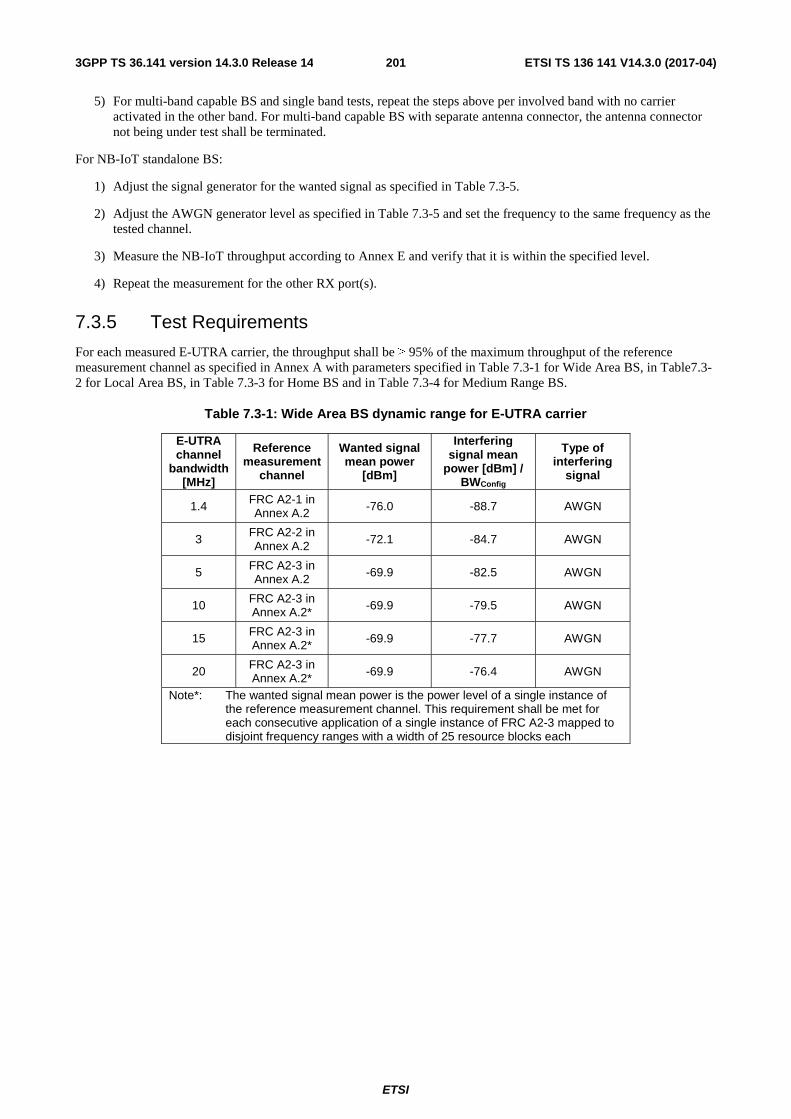
ETSI
ETSI TS 136 141 V14.3.0 (2017-04)2013GPP TS 36.141 version 14.3.0 Release 14
5) For multi-band capable BS and single band tests, repeat the steps above per involved band with no carrier activated in the other band. For multi-band capable BS with separate antenna connector, the antenna connector not being under test shall be terminated.
For NB-IoT standalone BS:
1) Adjust the signal generator for the wanted signal as specified in Table 7.3-5.
2) Adjust the AWGN generator level as specified in Table 7.3-5 and set the frequency to the same frequency as the tested channel.
3) Measure the NB-IoT throughput according to Annex E and verify that it is within the specified level.
4) Repeat the measurement for the other RX port(s).
7.3.5 Test Requirements
For each measured E-UTRA carrier, the throughput shall be ≥ 95% of the maximum throughput of the reference measurement channel as specified in Annex A with parameters specified in Table 7.3-1 for Wide Area BS, in Table7.3-2 for Local Area BS, in Table 7.3-3 for Home BS and in Table 7.3-4 for Medium Range BS.
Table 7.3-1: Wide Area BS dynamic range for E-UTRA carrier
E-UTRA channel
bandwidth [MHz]
Reference measurement
channel
Wanted signal mean power
[dBm]
Interfering signal mean
power [dBm] / BWConfig
Type of interfering
signal
1.4 FRC A2-1 in Annex A.2 -76.0 -88.7 AWGN
3 FRC A2-2 in Annex A.2 -72.1 -84.7 AWGN
5 FRC A2-3 in Annex A.2 -69.9 -82.5 AWGN
10 FRC A2-3 in Annex A.2* -69.9 -79.5 AWGN
15 FRC A2-3 in Annex A.2* -69.9 -77.7 AWGN
20 FRC A2-3 in Annex A.2* -69.9 -76.4 AWGN
Note*: The wanted signal mean power is the power level of a single instance of the reference measurement channel. This requirement shall be met for each consecutive application of a single instance of FRC A2-3 mapped to disjoint frequency ranges with a width of 25 resource blocks each

ETSI
ETSI TS 136 141 V14.3.0 (2017-04)2023GPP TS 36.141 version 14.3.0 Release 14
Table 7.3-2: Local Area BS dynamic range for E-UTRA carrier
E-UTRA channel
bandwidth [MHz]
Reference measurement
channel
Wanted signal mean power
[dBm]
Interfering signal mean
power [dBm] / BWConfig
Type of interfering
signal
1.4 FRC A2-1 in Annex A.2 -68.0 -80.7 AWGN
3 FRC A2-2 in Annex A.2 -64.1 -76.7 AWGN
5 FRC A2-3 in Annex A.2 -61.9 -74.5 AWGN
10 FRC A2-3 in Annex A.2* -61.9 -71.5 AWGN
15 FRC A2-3 in Annex A.2* -61.9 -69.7 AWGN
20 FRC A2-3 in Annex A.2* -61.9 -68.4 AWGN
Note*: The wanted signal mean power is the power level of a single instance of the reference measurement channel. This requirement shall be met for each consecutive application of a single instance of FRC A2-3 mapped to disjoint frequency ranges with a width of 25 resource blocks each
Table 7.3-3: Home BS dynamic range for E-UTRA carrier
E-UTRA channel
bandwidth [MHz]
Reference measurement
channel
Wanted signal mean power
[dBm]
Interfering signal mean
power [dBm] / BWConfig
Type of interfering
signal
1.4 FRC A2-1 in Annex A.2
-31.5 -44.2 AWGN
3 FRC A2-2 in Annex A.2
-27.6 -40.2 AWGN
5 FRC A2-3 in Annex A.2
-25.4 -38 AWGN
10 FRC A2-3 in Annex A.2*
-25. 4 -35 AWGN
15 FRC A2-3 in Annex A.2*
-25. 4 -33.2 AWGN
20 FRC A2-3 in Annex A.2*
-25. 4 -31.9 AWGN
Note*: The wanted signal mean power is the power level of a single instance of the reference measurement channel. This requirement shall be met for each consecutive application of a single instance of FRC A2-3 mapped to disjoint frequency ranges with a width of 25 resource blocks each

ETSI
ETSI TS 136 141 V14.3.0 (2017-04)2033GPP TS 36.141 version 14.3.0 Release 14
Table 7.3-4: Medium Range BS dynamic range for E-UTRA carrier
E-UTRA channel
bandwidth [MHz]
Reference measurement
channel
Wanted signal mean power
[dBm]
Interfering signal mean
power [dBm] / BWConfig
Type of interfering
signal
1.4 FRC A2-1 in Annex A.2 -71.0 -83.7 AWGN
3 FRC A2-2 in Annex A.2 -67.1 -79.7 AWGN
5 FRC A2-3 in Annex A.2 -64.9 -77.5 AWGN
10 FRC A2-3 in Annex A.2* -64.9 -74.5 AWGN
15 FRC A2-3 in Annex A.2* -64.9 -72.7 AWGN
20 FRC A2-3 in Annex A.2* -64.9 -71.4 AWGN
Note*: The wanted signal mean power is the power level of a single instance of the reference measurement channel. This requirement shall be met for each consecutive application of a single instance of FRC A2-3 mapped to disjoint frequency ranges with a width of 25 resource blocks each
For NB-IoT standalone operation, the throughput shall be ≥ 95% of the maximum throughput of the reference measurement channel as specified in Annex A with parameters specified in Table 7.3-5 for Wide Area BS.
Table 7.3-5: Wide Area BS dynamic range for NB-IoT standalone operation
NB-IoT channel
bandwidth [kHz]
Reference measurement
channel
Wanted signal mean power
[dBm]
Interfering signal mean
power [dBm] / BWChannel
Type of interfering
signal
200 FRC A15-1 in Annex A.15 -99.4 -96 AWGN
200 FRC A15-2 in Annex A.15 -105.3 -96 AWGN
For NB-IoT in-band or guard band operation, the throughput shall be ≥ 95% of the maximum throughput of the reference measurement channel as specified in Annex A with parameters specified in Table 7.3-6 for Wide Area BS.

ETSI
ETSI TS 136 141 V14.3.0 (2017-04)2043GPP TS 36.141 version 14.3.0 Release 14
Table 7.3-6: Wide Area BS dynamic range for NB-IoT in-band or guard band operation
NB-IoT channel
bandwidth [MHz]
Reference measurement
channel
Wanted signal mean power
[dBm]
Interfering signal mean
power [dBm] / BWChannel
Type of interfering
signal
1.4*
FRC A15-1 in Annex A.15 -99.4
-87.5 AWGN FRC A15-2 in Annex A.15 -105.3
3*
FRC A15-1 in Annex A.15 -99.4
-84.2 AWGN FRC A15-2 in Annex A.15 -105.3
5
FRC A15-1 in Annex A.15 -99.4
-82.0 AWGN FRC A15-2 in Annex A.15 -105.3
10
FRC A15-1 in Annex A.15 -99.4
-79.0 AWGN FRC A15-2 in Annex A.15 -105.3
15
FRC A15-1 in Annex A.15 -99.4
-77.2 AWGN FRC A15-2 in Annex A.15 -105.3
20
FRC A15-1 in Annex A.15 -99.4
-76.0 AWGN FRC A15-2 in Annex A.15 -105.3
Note*: 1.4 MHz and 3 MHz channel bandwidth is not applicable to guard band operation.
NOTE: If the above Test Requirement differs from the Minimum Requirement then the Test Tolerance applied for this test is non-zero. The relationship between Minimum Requirements and Test Requirements is defined in subclause 4.1 and the explanation of how the Minimum Requirement has been relaxed by the Test Tolerance is given in Annex G.
7.4 In-channel selectivity
7.4.1 Definition and applicability
In-channel selectivity (ICS) is a measure of the receiver ability to receive a wanted signal at its assigned resource block locations in the presence of an interfering signal received at a larger power spectral density. In this condition a throughput requirement shall be met for a specified reference measurement channel. The interfering signal shall be an E-UTRA signal as specified in Annex C and shall be time aligned with the wanted signal.
7.4.2 Minimum Requirement
The minimum requirement is in TS 36.104 [2] subclause 7.4.1.
7.4.3 Test purpose
The purpose of this test is to verify the BS receiver ability to suppress the IQ leakage.
7.4.4 Method of testing
7.4.4.1 Initial conditions
Test environment: normal; see subclause D.2.

ETSI
ETSI TS 136 141 V14.3.0 (2017-04)2053GPP TS 36.141 version 14.3.0 Release 14
RF channels to be tested for single carrier: B, M and T; see subclause 4.7
1) Connect the test equipment as shown in Annex I.2.3.
7.4.4.2 Procedure
For each supported E-UTRA channel BW:
1) Adjust the signal generator for the wanted E-UTRA signal as specified in Table 7.4-1 for Wide Area BS, in Table 7.4-2 for Local Area BS, in Table 7.4-3 for Home BS and in Table 7.4-4 for Medium Range BS on one side of the FC.
2) Adjust the signal generator for the interfering signal as specified in Table 7.4-1 for Wide Area BS, in Table 7.4-2 for Local Area BS, in Table 7.4-3 for Home BS and in Table 7.4-4 for Medium Range BS at opposite side of the FC and adjacent to the wanted signal.
3) Measure the throughput according to Annex E.
4) Repeat the measurement with the wanted signal on the other side of the FC, and the interfering signal at opposite side of the FC and adjacent to the wanted signal.
5) Repeat the measurement for the other RX port(s).
In addition, for a multi-band capable BS, the following step shall apply:
6) For multi-band capable BS and single band tests, repeat the steps above per involved band with no carrier activated in the other band. For multi-band capable BS with separate antenna connector, the antenna connector not being under test shall be terminated.
For each supported E-UTRA channel BW with NB-IoT in-band operation:
1) Adjust the signal generator for the wanted NB-IoT signal as specified in Table 7.4-5 for Wide Area BS with 15 kHz channel spacing and in Table 7.4-6 for Wide Area BS with 3.75 kHz channel spacing on one side of the FC.
2) Adjust the signal generator for the interfering signal as specified in Table 7.4-5 for Wide Area BS with 15 kHz channel spacing and in Table 7.4-6 for Wide Area BS with 3.75 kHz spacing at opposite side of the FC.
3) Measure the throughput according to Annex E.
4) Repeat the measurement with the wanted signal on the other side of the FC, and the interfering signal at opposite side of the FC.
5) Repeat the measurement for the other RX port(s).

ETSI
ETSI TS 136 141 V14.3.0 (2017-04)2063GPP TS 36.141 version 14.3.0 Release 14
7.4.5 Test Requirements
For each measured E-UTRA carrier, the throughput shall be ≥ 95% of the maximum throughput of the reference measurement channel as specified in Annex A with parameters specified in Table 7.4-1 for Wide Area BS, in Table7.4-2 for Local Area BS, in Table 7.4-3 for Home BS and in Table 7.4-4 for Medium Range BS.
Table 7.4-1: Wide Area BS in-channel selectivity for E-UTRA
E-UTRA channel
bandwidth (MHz)
Reference measurement
channel Wanted signal mean power [dBm]
Interfering signal mean power [dBm]
Type of interfering signal
f ≤ 3.0GHz 3.0GHz < f ≤ 4.2GHz
1.4 A1-4 in Annex A.1 -105.5 -105.1 -87 1.4 MHz E-UTRA
signal, 3 RBs
3 A1-5 in Annex A.1 -100.7 -100.3 -84
3 MHz E-UTRA signal, 6 RBs
5 A1-2 in Annex A.1 -98.6 -98.2 -81
5 MHz E-UTRA signal, 10 RBs
10 A1-3 in Annex A.1 -97.1 -96.7 -77
10 MHz E-UTRA signal, 25 RBs
15 A1-3 in Annex A.1* -97.1 -96.7 -77
15 MHz E-UTRA signal, 25 RBs*
20 A1-3 in Annex A.1* -97.1 -96.7 -77
20 MHz E-UTRA signal, 25 RBs*
Note*: Wanted and interfering signal are placed adjacently around FC
Table 7.4-2: Local Area BS in-channel selectivity for E-UTRA
E-UTRA channel
bandwidth (MHz)
Reference measurement
channel Wanted signal mean power [dBm]
Interfering signal mean power [dBm]
Type of interfering signal
f ≤ 3.0GHz 3.0GHz < f ≤ 4.2GHz
1.4 A1-4 in Annex A.1 -97.5 -97.1 -79 1.4 MHz E-UTRA
signal, 3 RBs
3 A1-5 in Annex A.1 -92.7 -92.3 -76 3 MHz E-UTRA
signal, 6 RBs
5 A1-2 in Annex A.1 -90.6 -90.2 -73 5 MHz E-UTRA
signal, 10 RBs
10 A1-3 in Annex A.1 -89.1 -88.7 -69 10 MHz E-UTRA
signal, 25 RBs
15 A1-3 in Annex A.1* -89.1 -88.7 -69 15 MHz E-UTRA
signal, 25 RBs*
20 A1-3 in Annex A.1* -89.1 -88.7 -69 20 MHz E-UTRA
signal, 25 RBs* Note*: Wanted and interfering signal are placed adjacently around Fc

ETSI
ETSI TS 136 141 V14.3.0 (2017-04)2073GPP TS 36.141 version 14.3.0 Release 14
Table 7.4-3 Home BS in-channel selectivity for E-UTRA
E-UTRA channel
bandwidth (MHz)
Reference measurement
channel Wanted signal mean power [dBm]
Interfering signal mean power [dBm]
Type of interfering signal
f ≤ 3.0GHz 3.0GHz < f ≤ 4.2GHz
1.4 A1-4 in Annex A.1 -97.5 -97.1 -79 1.4 MHz E-UTRA
signal, 3 RBs
3 A1-5 in Annex A.1 -92.7 -92.3 -76 3 MHz E-UTRA
signal, 6 RBs
5 A1-2 in Annex A.1 -90.6 -90.2 -73 5 MHz E-UTRA
signal, 10 RBs
10 A1-3 in Annex A.1 -89.1 -88.7 -69 10 MHz E-UTRA
signal, 25 RBs
15 A1-3 in Annex A.1* -89.1 -88.7 -69 15 MHz E-UTRA
signal, 25 RBs*
20 A1-3 in Annex
A.1* -89.1 -88.7 -69 20 MHz E-UTRA signal, 25 RBs*
Note*: Wanted and interfering signal are placed adjacently around Fc
Table 7.4-4 Medium Range BS in-channel selectivity for E-UTRA
E-UTRA channel
bandwidth (MHz)
Reference measurement
channel Wanted signal mean power [dBm]
Interfering signal mean power [dBm]
Type of interfering signal
f ≤ 3.0GHz 3.0GHz < f ≤
4.2GHz
1.4 A1-4 in Annex A.1 -100.5 -100.1 -82 1.4 MHz E-UTRA
signal, 3 RBs
3 A1-5 in Annex A.1 -95.7 -95.3 -79 3 MHz E-UTRA
signal, 6 RBs
5 A1-2 in Annex
A.1 -93.6 -93.2 -76 5 MHz E-UTRA signal, 10 RBs
10 A1-3 in Annex A.1 -92.1 -91.7 -72 10 MHz E-UTRA
signal, 25 RBs
15 A1-3 in Annex A.1* -92.1 -91.7 -72 15 MHz E-UTRA
signal, 25 RBs*
20 A1-3 in Annex
A.1* -92.1 -91.7 -72 20 MHz E-UTRA signal, 25 RBs*
Note*: Wanted and interfering signal are placed adjacently around Fc
NOTE: If the above Test Requirement differs from the Minimum Requirement then the Test Tolerance applied for this test is non-zero. The relationship between Minimum Requirements and Test Requirements is defined in subclause 4.1 and the explanation of how the Minimum Requirement has been relaxed by the Test Tolerance is given in Annex G.
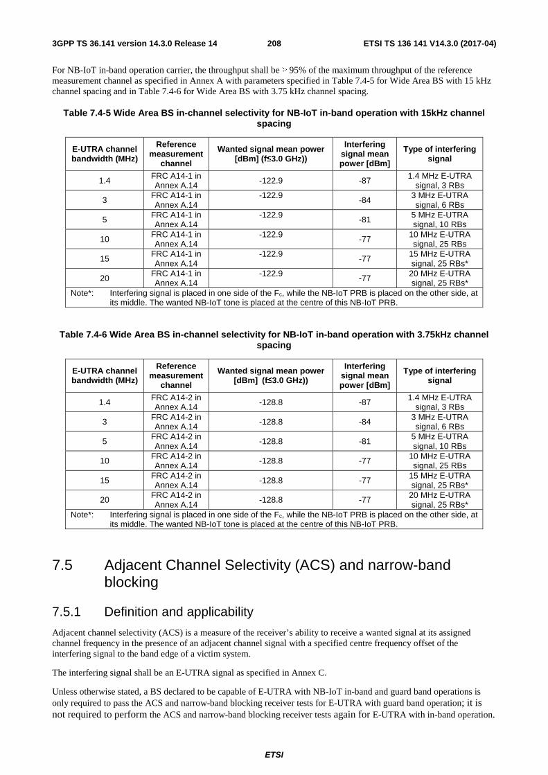
ETSI
ETSI TS 136 141 V14.3.0 (2017-04)2083GPP TS 36.141 version 14.3.0 Release 14
For NB-IoT in-band operation carrier, the throughput shall be ≥ 95% of the maximum throughput of the reference measurement channel as specified in Annex A with parameters specified in Table 7.4-5 for Wide Area BS with 15 kHz channel spacing and in Table 7.4-6 for Wide Area BS with 3.75 kHz channel spacing.
Table 7.4-5 Wide Area BS in-channel selectivity for NB-IoT in-band operation with 15kHz channel spacing
E-UTRA channel bandwidth (MHz)
Reference measurement
channel
Wanted signal mean power [dBm] (f≤3.0 GHz))
Interfering signal mean power [dBm]
Type of interfering signal
1.4 FRC A14-1 in Annex A.14 -122.9 -87 1.4 MHz E-UTRA
signal, 3 RBs
3 FRC A14-1 in Annex A.14
-122.9 -84
3 MHz E-UTRA signal, 6 RBs
5 FRC A14-1 in Annex A.14
-122.9 -81 5 MHz E-UTRA signal, 10 RBs
10 FRC A14-1 in Annex A.14
-122.9 -77 10 MHz E-UTRA signal, 25 RBs
15 FRC A14-1 in Annex A.14
-122.9 -77
15 MHz E-UTRA signal, 25 RBs*
20 FRC A14-1 in Annex A.14
-122.9 -77 20 MHz E-UTRA signal, 25 RBs*
Note*: Interfering signal is placed in one side of the Fc, while the NB-IoT PRB is placed on the other side, at its middle. The wanted NB-IoT tone is placed at the centre of this NB-IoT PRB.
Table 7.4-6 Wide Area BS in-channel selectivity for NB-IoT in-band operation with 3.75kHz channel spacing
E-UTRA channel bandwidth (MHz)
Reference measurement
channel
Wanted signal mean power [dBm] (f≤3.0 GHz))
Interfering signal mean power [dBm]
Type of interfering signal
1.4 FRC A14-2 in Annex A.14 -128.8 -87 1.4 MHz E-UTRA
signal, 3 RBs
3 FRC A14-2 in Annex A.14 -128.8 -84 3 MHz E-UTRA
signal, 6 RBs
5 FRC A14-2 in Annex A.14 -128.8 -81
5 MHz E-UTRA signal, 10 RBs
10 FRC A14-2 in Annex A.14 -128.8 -77 10 MHz E-UTRA
signal, 25 RBs
15 FRC A14-2 in Annex A.14 -128.8 -77 15 MHz E-UTRA
signal, 25 RBs*
20 FRC A14-2 in Annex A.14
-128.8 -77 20 MHz E-UTRA signal, 25 RBs*
Note*: Interfering signal is placed in one side of the Fc, while the NB-IoT PRB is placed on the other side, at its middle. The wanted NB-IoT tone is placed at the centre of this NB-IoT PRB.
7.5 Adjacent Channel Selectivity (ACS) and narrow-band blocking
7.5.1 Definition and applicability
Adjacent channel selectivity (ACS) is a measure of the receiver’s ability to receive a wanted signal at its assigned channel frequency in the presence of an adjacent channel signal with a specified centre frequency offset of the interfering signal to the band edge of a victim system.
The interfering signal shall be an E-UTRA signal as specified in Annex C.
Unless otherwise stated, a BS declared to be capable of E-UTRA with NB-IoT in-band and guard band operations is only required to pass the ACS and narrow-band blocking receiver tests for E-UTRA with guard band operation; it is not required to perform the ACS and narrow-band blocking receiver tests again for E-UTRA with in-band operation.

ETSI
ETSI TS 136 141 V14.3.0 (2017-04)2093GPP TS 36.141 version 14.3.0 Release 14
7.5.2 Minimum Requirement
The minimum requirement is in TS 36.104 [2] subclause 7.5.
7.5.3 Test purpose
The test purpose is to verify the ability of the BS receiver filter to suppress interfering signals in the channels adjacent to the wanted channel.
7.5.4 Method of test
7.5.4.1 Initial conditions
Test environment: normal; see subclause D.2.
RF channels to be tested for single carrier: B, M and T; see subclause 4.7.
Base Station RF Bandwidth edge position to be tested for multi-carrier and/or CA: MRFBW in single-band operation, see subclause 4.7.1; BRFBW_T’RFBW and B’RFBW_TRFBW in multi-band operation, see subclause 4.7.1.
1) Set-up the measurement system as shown in Annex I.2.4.
7.5.4.2 Procedure for Adjacent Channel Selectivity
For E-UTRA and E-UTRA with NB-IoT in-band or guard band operation:
1) Generate the E-UTRA wanted signal using the applicable test configuration specified in subclause 4.10 and 4.11 and adjust the input level to the base station under test to the level specified in Table 7.5-3 for E-UTRA Wide Area BS, in Table7.5-4 for E-UTRA Local Area BS, in Table 7.5-5 for E-UTRA Home BS and in Table 7.5-6 for E-UTRA Medium Range BS.
For a BS declared to be capable of NB-IoT in-band or guard band operation,, generate the NB-IoT wanted signal using the applicable test configuration specified in subclause 4.10 and 4.11 and adjust the input level to the base station under test to the level specified in Table 7.5-7 for NB-IoT in-band operation Wide Area BS and Table 7.5-8 for NB-IoT in guard band operation Wide Area BS.
2) Set-up the interfering signal at the adjacent channel frequency and adjust the interfering signal level at the base station input to the level defined in Table 7.5-3 for E-UTRA Wide Area BS, in Table7.5-4 for E-UTRA Local Area BS, in Table 7.5-5 for E-UTRA Home BS, in Table 7.5-6 for E-UTRA Medium Range BS, in Table 7.5-7 for NB-IoT in-band operation Wide Area BS and Table 7.5-8 for NB-IoT in guard band operation Wide Area BS.
3) Measure the E-UTRA throughput according to Annex E, for multi-carrier and/or CA operation the throughput shall be measured for relevant carriers specified by the test configuration specified in subclause 4.10 and 4.11.
For a BS declared to be capable of NB-IoT in-band or guard band operation, measure the NB-IoT throughput according to Annex E, for multi-carrier the throughput shall be measured for relevant carriers specified by the test configuration specified in subclause 4.10 and 4.11.
4) Repeat the test for the port(s), which was (were) terminated.
In addition, for a multi-band capable BS with separate antenna connectors, the following steps shall apply:
5) For single band tests, repeat the steps above per involved band where single band test configurations shall apply with no carrier activated in the other band.
Interfering signal shall first be applied on the same port as the wanted signal. The test shall be repeated with the interfering signal applied on the other port (if any) mapped to the same receiver as the wanted signal. Any antenna connector with no signal applied in case of single-band or multi-band test shall be terminated.
6) Repeat step 5) with the wanted signal for the other band(s) applied on the respective port(s).
For NB-IoT standalone operation:

ETSI
ETSI TS 136 141 V14.3.0 (2017-04)2103GPP TS 36.141 version 14.3.0 Release 14
1) Generate the NB-IoT wanted signal using the applicable test configuration specified in subclause 4.10 and 4.11 and adjust the input level to the base station under test to the level specified in Table 7.5-9 for NB-IoT standalone Wide Area BS.
2) Set-up the interfering signal at the adjacent channel frequency and adjust the interfering signal level at the base station input to the level defined in Table 7.5-9 for NB-IoT standalone Wide Area BS.
3) Measure NB-IoT throughput according to Annex E.
4) Repeat the test for the port(s), which was (were) terminated.
7.5.4.3 Procedure for narrow-band blocking
For E-UTRA and E-UTRA with NB-IoT in-band or guard band BS:
1) For FDD BS declared to be capable of single carrier operation only, start BS transmission according to E-TM 1.1 at manufacturer’s declared rated output power.
For a FDD BS declared to be capable of multi-carrier and/or CA operation, set the BS to transmit according to E-TM 1.1 on all carriers configured using the applicable test configuration and corresponding power setting specified in sub-clause 4.10 and 4.11.
For BS declared to be capable of NB-IoT in-band or guard band operation single carrier only, start BS transmission according to N-TM at manufacturer’s declared rated output power.
For a BS declared to be capable of NB-IoT multi-carrier, set the BS to transmit according to N-TM on all carriers configured using the applicable test configuration and corresponding power setting specified in sub-clause 4.10 and 4.11.
2) Generate the E-UTRA wanted signal using the applicable test configuration specified in subclause 4.10 and 4.11 and adjust the input level to the base station under test to the level specified in Table 7.5-1.
For a BS declared to be capable of NB-IoT in-band or guard band operation, generate the NB-IoT wanted signal using the applicable test configuration specified in subclause 4.10 and 4.11 and adjust the input level to the base station under test to the level specified in Table 7.5-1a for NB-IoT in-band operation and Table 7.5-1b for NB-IoT guard band operation.
3) Adjust the interfering signal level at the base station input to the level defined in Table 7.5-1 for E-UTRA, in Table 7.5-1a for NB-IoT in-band operation and Table 7.5-1b for NB-IoT guard band operation. Set-up and sweep the interfering RB centre frequency offset to the channel edge of the wanted signal according to Table 7.5-2.
4) Measure the E-UTRA throughput according to Annex E, for multi-carrier and/or CA operation the throughput shall be measured for relevant carriers specified by the test configuration specified in subclause 4.10 and 4.11.
For a BS declared to be capable of NB-IoT in-band or guard band operation, measure the NB-IoT throughput according to Annex E, for multi-carrier the throughput shall be measured for relevant carriers specified by the test configuration specified in subclause 4.10 and 4.11.
5) Repeat the test for the port(s), which was (were) terminated.
In addition, for a multi-band capable BS with separate antenna connectors, the following steps shall apply:
6) For single band tests, repeat the steps above per involved band where single band test configurations and test models shall apply with no carrier activated in the other band.
7) Interfering signal shall first be applied on the same port as the wanted signal. The test shall be repeated with the interfering signal applied on the other port (if any) mapped to the same receiver as the wanted signal. Any antenna connector with no signal applied in case of single-band or multi-band test shall be terminated.
8) Repeat step 7) with the wanted signal for the other band(s) applied on the respective port(s).
For NB-IoT standalone BS:

ETSI
ETSI TS 136 141 V14.3.0 (2017-04)2113GPP TS 36.141 version 14.3.0 Release 14
1) For BS declared to be capable of NB-IoT standalone single carrier only, start BS transmission according to N-TM at manufacturer’s declared rated output power.
For a BS declared to be capable of NB-IoT multi-carrier, set the BS to transmit according to N-TM on all carriers configured using the applicable test configuration and corresponding power setting specified in sub-clause 4.10 and 4.11.
2) Generate the NB-IoT wanted signal using the applicable test configuration specified in subclause 4.10 and 4.11 and adjust the input level to the base station under test to the level specified in Table 7.5-1c.
3) Adjust the interfering signal level at the base station input to the level defined in Table 7.5-1c. Set-up and sweep the interfering RB centre frequency offset to the channel edge of the wanted signal according to Table 7.5-2a.
4) Measure the NB-IoT throughput according to Annex E, for multi-carrier the throughput shall be measured for relevant carriers specified by the test configuration specified in subclause 4.10 and 4.11.
5) Repeat the test for the port(s), which was (were) terminated.
For E-UTRA and NB-IoT standalone BS:
1) Set the BS to transmit according to E-TM 1.1 on all E-UTRA carriers and according to N-TM on all NB-IoT carriers configured using the applicable test configuration and corresponding power setting specified in sub-clause 4.10 and 4.11.
2) Generate the E-UTRA wanted signal using the applicable test configuration specified in subclause 4.10 and 4.11 and adjust the input level to the base station under test to the level specified in Table 7.5-1.
Generate the NB-IoT wanted signal using the applicable test configuration specified in subclause 4.10 and 4.11 and adjust the input level to the base station under test to the level specified in Table 7.5-1c.
3) a) On the side where E-UTRA signal is positioned:
Adjust the interfering signal level at the base station input to the level defined in Table 7.5-1 for E-UTRA. Set-up and sweep the interfering RB centre frequency offset to the channel edge of the wanted signal according to Table 7.5-2.
b) On the side where NB-IoT signal is positioned:
Adjust the interfering signal level at the base station input to the level defined in Table 7.5-1c. Set-up and sweep the interfering RB centre frequency offset to the channel edge of the wanted signal according to Table 7.5-2a.
4) Measure the E-UTRA throughput and the NB-IoT throughput according to Annex E, for multi-carrier the throughput shall be measured for relevant carriers specified by the test configuration specified in subclause 4.10 and 4.11.
5) Repeat the test for the port(s), which was (were) terminated.
7.5.5 Test Requirements
For each measured E-UTRA carrier, the throughput shall be ≥ 95% of the maximum throughput of the reference measurement channel.
For each measured NB-IoT carrier, the throughput shall be ≥ 95% of the maximum throughput of the reference measurement channel.
For E-UTRA Wide Area BS, the wanted and the interfering signal coupled to the BS antenna input are specified in Table 7.5-1 and 7.5-2 for narrowband blocking and 7.5-3 for ACS. The reference measurement channel for the wanted signal is specified in Table 7.2-1 for each channel bandwidth and further specified in Annex A.
For E-UTRA Medium Range BS, the wanted and the interfering signal coupled to the BS antenna input are specified in Tables 7.5-1 and 7.5-2 for narrowband blocking and in Table 7.5-6 for ACS. The reference measurement channel for the wanted signal is specified in Table 7.2-4 for each channel bandwidth and further specified in Annex A.

ETSI
ETSI TS 136 141 V14.3.0 (2017-04)2123GPP TS 36.141 version 14.3.0 Release 14
For E-UTRA Local Area BS, the wanted and the interfering signal coupled to the BS antenna input are specified in Tables 7.5-1 and 7.5-2 for narrowband blocking and 7.5-4 for ACS. The reference measurement channel for the wanted signal is specified in Table 7.2-2 for each channel bandwidth and further specified in Annex A.
For E-UTRA Home BS, the wanted and the interfering signal coupled to the BS antenna input are specified in Table 7.5-1 and 7.5-2 for narrowband blocking and 7.5-5 for ACS. The reference measurement channel for the wanted signal is specified in Table 7.2-3 for each channel bandwidth and further specified in Annex A.
For E-UTRA Wide Area BS declared to be capable of NB-IoT in-band, the E-UTRA wanted, the NB-IoT wanted and the interfering signal coupled to the BS antenna input are specified in Table 7.5-1, 7.5-1a and 7.5-2 for narrowband blocking and 7.5-3 and 7.5-3a for ACS. The reference measurement channel for the E-UTRA wanted signal is specified in Table 7.2-1 for each channel bandwidth and further specified in Annex A. The reference measurement channel for the NB-IoT wanted signal is specified in Table 7.2-5 for each sub-carrier spacing and further specified in Annex A.
For E-UTRA Wide Area BS declared to be capable of NB-IoT guard band, the E-UTRA wanted, the NB-IoT wanted and the interfering signal coupled to the BS antenna input are specified in Table 7.5-1, 7.5-1b and 7.5-2 for narrowband blocking and 7.5-3 and 7.5-3b for ACS. The reference measurement channel for the E-UTRA wanted signal is specified in Table 7.2-1 for each channel bandwidth and further specified in Annex A. The reference measurement channel for the NB-IoT wanted signal is specified in Table 7.2-5 for each sub-carrier spacing and further specified in Annex A.
For NB-IoT standalone Wide Area BS, the NB-IoT wanted and the interfering signal coupled to the BS antenna input are specified in Table 7.5-1c and 7.5-2a for narrowband blocking and 7.5-3c for ACS. The reference measurement channel for the NB-IoT wanted signal is specified in Table 7.2-5 for each sub-carrier spacing and further specified in Annex A.
The ACS and narrowband blocking requirement is always applicable outside the Base Station RF Bandwidth or Maximum Radio Bandwidth. The interfering signal offset is defined relative to the Base station RF Bandwidth edges or Maximum Radio Bandwidth edges.
For a BS operating in non-contiguous spectrum within any operating band, the ACS requirement applies in addition inside any sub-block gap, in case the sub-block gap size is at least as wide as the E-UTRA interfering signal in Tables 7.5-3, 7.5-4 and 7.5-6. The interfering signal offset is defined relative to the sub-block edges inside the sub-block gap.
For a BS capable of multi-band operation, the ACS requirement applies in addition inside any Inter RF Bandwidth gap, in case the Inter RF Bandwidth gap size is at least as wide as the E-UTRA interfering signal in Tables 7.5-3, 7.5-4 and 7.5-6. The interfering signal offset is defined relative to the Base Station RF Bandwidth edges inside the Inter RF Bandwidth gap.
For a BS operating in non-contiguous spectrum within any operating band, the narrowband blocking requirement applies in addition inside any sub-block gap, in case the sub-block gap size is at least as wide as the channel bandwidth of the E-UTRA interfering signal in Table 7.5-2. The interfering signal offset is defined relative to the sub-block edges inside the sub-block gap.
For a BS capable of multi-band operation, the narrowband blocking requirement applies in addition inside any Inter RF Bandwidth gap, in case the Inter RF Bandwidth gap size is at least as wide as the E-UTRA interfering signal in Table 7.5-2. The interfering signal offset is defined relative to the Base Station RF Bandwidth edges inside the Inter RF Bandwidth gap.
Table 7.5-1: Narrowband blocking requirement
Wanted signal mean power
[dBm]
Interfering signal mean power
[dBm]
Type of interfering signal
Wide Area BS PREFSENS + 6dB* -49 See Table 7.5-2 Medium Range
BS PREFSENS + 6dB* -44 See Table 7.5-2
Local Area BS PREFSENS +6dB* -41 See Table 7.5-2 Home BS PREFSENS + 14dB* -33 See Table 7.5-2
Note*: PREFSENS depends on the channel bandwidth as specified in TS 36.104 [2] subclause 7.2.1.

ETSI
ETSI TS 136 141 V14.3.0 (2017-04)2133GPP TS 36.141 version 14.3.0 Release 14
Table 7.5.1a: Narrowband blocking requirement for NB-IoT in-band operation BS
E-UTRA channel BW of the
lowest/highest carrier received
[MHz]
NB-IoT Wanted signal mean power
[dBm]
Interfering signal mean power
[dBm]
Type of interfering signal
Wide Area BS
1.4 PREFSENS + 11 dB* -49 See Table 7.5.2 3 PREFSENS + 11 dB* -49 See Table 7.5.2 5 PREFSENS + 8 dB* -49 See Table 7.5.2 10 PREFSENS + 6 dB* -49 See Table 7.5.2 15 PREFSENS + 6 dB* -49 See Table 7.5.2 20 PREFSENS + 6 dB* -49 See Table 7.5.2
Note*: PREFSENS depends on the sub-carrier spacing as specified in TS 36.104 [2] subclause 7.2.1..
Table 7.5.1b: Narrowband blocking requirement for NB-IoT guard band operation BS
E-UTRA channel BW of the
lowest/highest carrier received
[MHz]
NB-IoT Wanted signal mean power
[dBm]
Interfering signal mean power [dBm]
Type of interfering signal
Wide Area BS
5 PREFSENS + 11 dB* -49 See Table 7.5.2 10 PREFSENS + 6 dB* -49 See Table 7.5.2 15 PREFSENS + 6 dB* -49 See Table 7.5.2 20 PREFSENS + 6 dB* -49 See Table 7.5.2
Note: The mentioned desens values consider only 1 NB-IoT in the guard band. Note*: PREFSENS depends on the sub-carrier spacing as specified in TS 36.104 [2] subclause
7.2.1.
Table 7.5.1c: Narrowband blocking requirement for NB-IoT standalone
NB-IoT channel
bandwidth of the lowest/highest carrier received
[kHz]
Wanted signal mean power [dBm]
Interfering signal mean power [dBm]
Type of interfering
signal
Wide Area BS 200 PREFSENS +
12 dB* -49 See Table 7.5.2a
Note*: PREFSENS depends on the sub-carrier spacing as specified in TS 36.104 [2] subclause 7.2.1.
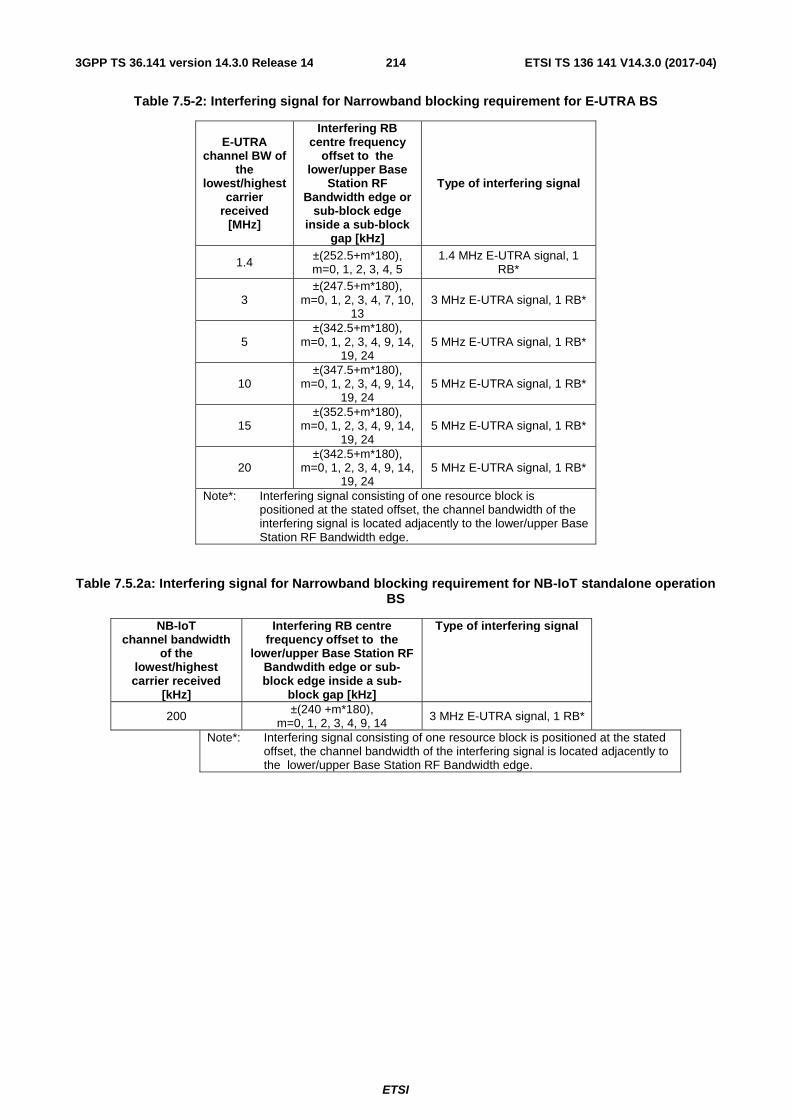
ETSI
ETSI TS 136 141 V14.3.0 (2017-04)2143GPP TS 36.141 version 14.3.0 Release 14
Table 7.5-2: Interfering signal for Narrowband blocking requirement for E-UTRA BS
E-UTRA channel BW of
the lowest/highest
carrier received
[MHz]
Interfering RB centre frequency
offset to the lower/upper Base
Station RF Bandwidth edge or
sub-block edge inside a sub-block
gap [kHz]
Type of interfering signal
1.4 ±(252.5+m*180), m=0, 1, 2, 3, 4, 5
1.4 MHz E-UTRA signal, 1 RB*
3 ±(247.5+m*180),
m=0, 1, 2, 3, 4, 7, 10, 13
3 MHz E-UTRA signal, 1 RB*
5 ±(342.5+m*180),
m=0, 1, 2, 3, 4, 9, 14, 19, 24
5 MHz E-UTRA signal, 1 RB*
10 ±(347.5+m*180),
m=0, 1, 2, 3, 4, 9, 14, 19, 24
5 MHz E-UTRA signal, 1 RB*
15 ±(352.5+m*180),
m=0, 1, 2, 3, 4, 9, 14, 19, 24
5 MHz E-UTRA signal, 1 RB*
20 ±(342.5+m*180),
m=0, 1, 2, 3, 4, 9, 14, 19, 24
5 MHz E-UTRA signal, 1 RB*
Note*: Interfering signal consisting of one resource block is positioned at the stated offset, the channel bandwidth of the interfering signal is located adjacently to the lower/upper Base Station RF Bandwidth edge.
Table 7.5.2a: Interfering signal for Narrowband blocking requirement for NB-IoT standalone operation BS
NB-IoT channel bandwidth
of the lowest/highest carrier received
[kHz]
Interfering RB centre frequency offset to the
lower/upper Base Station RF Bandwdith edge or sub-block edge inside a sub-
block gap [kHz]
Type of interfering signal
200 ±(240 +m*180), m=0, 1, 2, 3, 4, 9, 14
3 MHz E-UTRA signal, 1 RB*
Note*: Interfering signal consisting of one resource block is positioned at the stated offset, the channel bandwidth of the interfering signal is located adjacently to the lower/upper Base Station RF Bandwidth edge.

ETSI
ETSI TS 136 141 V14.3.0 (2017-04)2153GPP TS 36.141 version 14.3.0 Release 14
Table 7.5-3: Adjacent channel selectivity for E-UTRA Wide Area BS
E-UTRA channel
bandwidth of the
lowest/highest carrier
received [MHz]
Wanted signal mean power [dBm]
Interfering signal mean power
[dBm]
Interfering signal centre frequency offset from the
lower/upper Base Station RF
Bandwidth edge or sub-block edge inside a sub-block
gap [MHz]
Type of interfering signal
1.4 PREFSENS + 11dB* -52 ±0.7025 1.4MHz E-UTRA signal 3 PREFSENS + 8dB* -52 ±1.5075 3MHz E-UTRA signal 5 PREFSENS + 6dB* -52 ±2.5025 5MHz E-UTRA signal 10 PREFSENS + 6dB* -52 ±2.5075 5MHz E-UTRA signal 15 PREFSENS + 6dB* -52 ±2.5125 5MHz E-UTRA signal 20 PREFSENS + 6dB* -52 ±2.5025 5MHz E-UTRA signal
Note*: PREFSENS depends on the channel bandwidth as specified in TS 36.104 [2] subclause 7.2.1.
Table 7.5.3a: Adjacent channel selectivity for NB-IoT in-band operation Wide Area BS
E-UTRA channel
bandwidth of the
lowesthighest carrier
received [MHz]
NB-IoT wanted signal mean power
[dBm]
Interfering signal mean power [dBm]
Interfering signal centre frequency offset from the
lower/upper Base Station RF Bandwidth
edge or sub-block edge inside a sub-block gap [MHz]
Type of interfering signal
1.4 PREFSENS + 11dB* -52 ±0.7025 1.4MHz E-UTRA signal 3 PREFSENS + 8dB* -52 ±1.5075 3MHz E-UTRA signal 5 PREFSENS + 6dB* -52 ±2.5025 5MHz E-UTRA signal
10 PREFSENS + 6dB* -52 ±2.5075 5MHz E-UTRA signal 15 PREFSENS + 6dB* -52 ±2.5125 5MHz E-UTRA signal 20 PREFSENS + 6dB* -52 ±2.5025 5MHz E-UTRA signal
Note*: PREFSENS depends on the sub-carrier spacing as specified in TS 36.104 [2] subclause 7.2.1.
Table 7.5.3b: Adjacent channel selectivity NB-IoT guard band operation Wide Area BS
E-UTRA channel
bandwidth of the
lowesthighest carrier
received [MHz]
NB-IoT wanted signal mean power
[dBm]
Interfering signal mean power [dBm]
Interfering signal centre frequency offset from the
lower/upper Base Station RF Bandwidth
edge or sub-block edge inside a sub-block gap [MHz]
Type of interfering signal
5 PREFSENS + 10 dB* -52 ±2.5025 5MHz E-UTRA signal 10 PREFSENS + 8 dB* -52 ±2.5075 5MHz E-UTRA signal 15 PREFSENS + 6 dB* -52 ±2.5125 5MHz E-UTRA signal 20 PREFSENS + 6 dB* -52 ±2.5025 5MHz E-UTRA signal
Note*: PREFSENS depends on the sub-carrier spacing as specified in TS 36.104 [2] subclause 7.2.1.

ETSI
ETSI TS 136 141 V14.3.0 (2017-04)2163GPP TS 36.141 version 14.3.0 Release 14
Table 7.5.3c: Adjacent channel selectivity for NB-IoT standalone Wide Area BS
NB-IoT channel
bandwidth of the
lowest/highest carrier
received [kHz]
Wanted signal mean power [dBm]
Interfering signal mean power [dBm]
Interfering signal centre frequency offset to the
lower/upper Base Station RF Bandwidth
edge or sub-block edge inside a sub-block gap
[kHz]
Type of interfering signal
200 PREFSENS + 19.5dB* -52 ±100 180 kHz NB-IoT signal Note*: PREFSENS depends on the sub-carrier spacing as specified in TS 36.104 [2] subclause 7.2.1.
Table 7.5-4: Adjacent channel selectivity for E-UTRA Local Area BS
E-UTRA channel
bandwidth of the
lowest/highest carrier
received [MHz]
Wanted signal mean power [dBm]
Interfering signal mean power
[dBm]
Interfering signal centre frequency offset from the
lowerupper Base Station RF
Bandwidth edge or sub-block edge inside a sub-block gap
[MHz]
Type of interfering signal
1.4 PREFSENS + 11dB* -44 ±0.7025 1.4MHz E-UTRA signal 3 PREFSENS + 8dB* -44 ±1.5075 3MHz E-UTRA signal 5 PREFSENS + 6dB* -44 ±2.5025 5MHz E-UTRA signal 10 PREFSENS + 6dB* -44 ±2.5075 5MHz E-UTRA signal 15 PREFSENS + 6dB* -44 ±2.5125 5MHz E-UTRA signal 20 PREFSENS + 6dB* -44 ±2.5025 5MHz E-UTRA signal
Note*: PREFSENS depends on the channel bandwidth as specified in TS 36.104 [2] subclause 7.2.1.
Table 7.5-5: Adjacent channel selectivity for E-UTRA Home BS
E-UTRA channel
bandwidth [MHz]
Wanted signal mean power [dBm]
Interfering signal mean power [dBm]
Interfering signal centre frequency offset from the channel edge of
the wanted signal [MHz]
Type of interfering signal
1.4 PREFSENS + 27dB* -28 0.7025 1.4MHz E-UTRA signal 3 PREFSENS + 24dB* -28 1.5075 3MHz E-UTRA signal 5 PREFSENS + 22dB* -28 2.5025 5MHz E-UTRA signal 10 PREFSENS + 22dB* -28 2.5075 5MHz E-UTRA signal 15 PREFSENS + 22dB* -28 2.5125 5MHz E-UTRA signal 20 PREFSENS + 22dB* -28 2.5025 5MHz E-UTRA signal
Note*: PREFSENS depends on the channel bandwidth as specified in TS 36.104 [2] subclause 7.2.1.

ETSI
ETSI TS 136 141 V14.3.0 (2017-04)2173GPP TS 36.141 version 14.3.0 Release 14
Table 7.5-6: Adjacent channel selectivity for E-UTRA Medium Range BS
E-UTRA channel
bandwidth of the
lowest/highest carrier
received [MHz]
Wanted signal mean power [dBm]
Interfering signal mean power
[dBm]
Interfering signal centre frequency offset from the
lower/upper Base Station RF
Bandwidth edge or sub-block edge inside a sub-block
gap [MHz]
Type of interfering signal
1.4 PREFSENS + 11dB* -47 ±0.7025 1.4MHz E-UTRA signal 3 PREFSENS + 8dB* -47 ±1.5075 3MHz E-UTRA signal 5 PREFSENS + 6dB* -47 ±2.5025 5MHz E-UTRA signal 10 PREFSENS + 6dB* -47 ±2.5075 5MHz E-UTRA signal 15 PREFSENS + 6dB* -47 ±2.5125 5MHz E-UTRA signal 20 PREFSENS + 6dB* -47 ±2.5025 5MHz E-UTRA signal
Note*: PREFSENS depends on the channel bandwidth as specified in TS 36.104 [2] subclause 7.2.1.
NOTE: If the above Test Requirement differs from the Minimum Requirement then the Test Tolerance applied for this test is non-zero. The relationship between Minimum Requirements and Test Requirements is defined in subclause 4.1 and the explanation of how the Minimum Requirement has been relaxed by the Test Tolerance is given in Annex G.
7.6 Blocking
7.6.1 Definition and applicability
The blocking characteristics is a measure of the receiver ability to receive a wanted signal at its assigned channel in the presence of an unwanted interferer, which are either a 1.4MHz, 3MHz or 5MHz E-UTRA signal for in-band blocking or a CW signal for out-of-band blocking. The interfering E-UTRA signal shall be as specified in Annex C.
The blocking performance requirement applies as specified in the Tables 7.6-1, 7.6-1a, 7.6-1b, 7.6-1c, 7.6-1d, 7.6-1e, 7.6-2 and 7.6-2a in clause 7.6.5.
Unless otherwise stated, a BS declared to be capable of E-UTRA with NB-IoT in-band and guard band operations is only required to pass the blocking receiver tests for E-UTRA with guard band operation; it is not required to perform the blocking receiver tests again for E-UTRA with in-band operation.
7.6.2 Minimum Requirements
The minimum requirement is in TS 36.104 [2] subclause 7.6.1.
7.6.3 Test purpose
The test stresses the ability of the BS receiver to withstand high-level interference from unwanted signals at specified frequency offsets without undue degradation of its sensitivity.
7.6.4 Method of test
7.6.4.1 Initial conditions
Test environment: normal; see subclause D.2.
RF channels to be tested for single carrier: M see subclause 4.7. The BS shall be configured to operate as close to the centre of the operating band (see Table 5.5-1) as possible.
Base Station RF Bandwidth positions to be tested for multi-carrier and/or CA: MRFBW in single-band operation, see subclause 4.7.1; BRFBW_T’RFBW and B’RFBW_TRFBW in multi-band operation, see subclause 4.7.1.
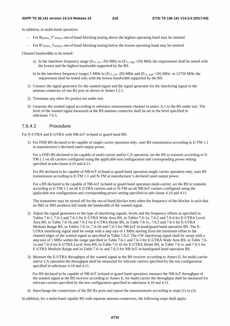
ETSI
ETSI TS 136 141 V14.3.0 (2017-04)2183GPP TS 36.141 version 14.3.0 Release 14
In addition, in multi-band operation:
- For BRFBW_T’RFBW, out-of-band blocking testing above the highest operating band may be omitted
- For B’RFBW_TRFBW, out-of-band blocking testing below the lowest operating band may be omitted
Channel bandwidths to be tested:
a) In the interferer frequency range (FUL_low -20) MHz to (FUL_high +20) MHz the requirement shall be tested with the lowest and the highest bandwidth supported by the BS.
b) In the interferer frequency ranges 1 MHz to (FUL_low -20) MHz and (FUL_high +20) MHz to 12750 MHz the requirement shall be tested only with the lowest bandwidth supported by the BS.
1) Connect the signal generator for the wanted signal and the signal generator for the interfering signal to the antenna connector of one Rx port as shown in Annex I.2.5.
2) Terminate any other Rx port(s) not under test.
3) Generate the wanted signal according to reference measurement channel in annex A.1 to the BS under test. The level of the wanted signal measured at the BS antenna connector shall be set to the level specified in subclause 7.6.5.
7.6.4.2 Procedure
For E-UTRA and E-UTRA with NB-IoT in-band or guard band BS:
1) For FDD BS declared to be capable of single carrier operation only, start BS transmission according to E-TM 1.1 at manufacturer’s declared rated output power.
For a FDD BS declared to be capable of multi-carrier and/or CA operation, set the BS to transmit according to E-TM 1.1 on all carriers configured using the applicable test configuration and corresponding power setting specified in sub-clause 4.10 and 4.11.
For BS declared to be capable of NB-IoT in-band or guard band operation single carrier operation only, start BS transmission according to E-TM 1.1 and N-TM at manufacturer’s declared rated output power.
For a BS declared to be capable of NB-IoT in-band or guard band operation multi-carrier, set the BS to transmit according to E-TM 1.1 on all E-UTRA carriers and to N-TM on all NB-IoT carriers configured using the applicable test configuration and corresponding power setting specified in sub-clause 4.10 and 4.11.
The transmitter may be turned off for the out-of-band blocker tests when the frequency of the blocker is such that no IM2 or IM3 products fall inside the bandwidth of the wanted signal.
2) Adjust the signal generators to the type of interfering signals, levels and the frequency offsets as specified in Tables 7.6-1, 7.6-2 and 7.6-3 for E-UTRA Wide Area BS, in Tables 7.6-1a, 7.6-2 and 7.6-4 for E-UTRA Local Area BS, in Table 7.6-1b and 7.6-2 for E-UTRA Home BS, in Table 7.6-1c, 7.6.2 and 7.6-5 for E-UTRA Medium Range BS, in Tables 7.6-1e, 7.6-2b and 7.6-3 for NB-IoT in-band/guard band operation BS. The E-UTRA interfering signal shall be swept with a step size of 1 MHz starting from the minimum offset to the channel edges of the wanted signal as specified in Table 7.6-2. The CW interfering signal shall be swept with a step size of 1 MHz within the range specified in Table 7.6-1 and 7.6-3 for E-UTRA Wide Area BS, in Table 7.6-1a and 7.6-4 for E-UTRA Local Area BS, in Table 7.6-1b for E-UTRA Home BS, in Table 7.6-1c and 7.6-5 for E-UTRA Medium Range and in Table 7.6-1e and 7.6-3 for NB-IoT in-band/guard band operation BS.
3) Measure the E-UTRA throughput of the wanted signal at the BS receiver according to Annex E, for multi-carrier and/or CA operation the throughput shall be measured for relevant carriers specified by the test configuration specified in subclause 4.10 and 4.11.
For BS declared to be capable of NB-IoT in-band or guard band operation, measure the NB-IoT throughput of the wanted signal at the BS receiver according to Annex E, for multi-carrier the throughput shall be measured for relevant carriers specified by the test configuration specified in subclause 4.10 and 4.11.
4) Interchange the connections of the BS Rx ports and repeat the measurements according to steps (1) to (3).
In addition, for a multi-band capable BS with separate antenna connectors, the following steps shall apply:

ETSI
ETSI TS 136 141 V14.3.0 (2017-04)2193GPP TS 36.141 version 14.3.0 Release 14
5) For single band tests, repeat the steps above per involved band where single band test configurations and test models shall apply with no carrier activated in the other band.
Interfering signal shall first be applied on the same port as the wanted signal. The test shall be repeated with the interfering signal applied on the other port (if any) mapped to the same receiver as the wanted signal. Any antenna connector with no signal applied in case of single-band or multi-band test shall be terminated.
6) Repeat step 5) with the wanted signal for the other band(s) applied on the respective port(s).
For NB-IoT standalone BS:
1) For BS declared to be capable of NB-IoT standalone single carrier only, start BS transmission according to N-TM at manufacturer’s declared rated output power.
For a BS declared to be capable of NB-IoT multi-carrier, set the BS to transmit according to N-TM on all carriers configured using the applicable test configuration and corresponding power setting specified in sub-clause 4.10 and 4.11.
The transmitter may be turned off for the out-of-band blocker tests when the frequency of the blocker is such that no IM2 or IM3 products fall inside the bandwidth of the wanted signal.
2) Adjust the signal generators to the type of interfering signals, levels and the frequency offsets as specified in Tables 7.6-1d, 7.6-2a and 7.6-3. The E-UTRA interfering signal shall be swept with a step size of 1 MHz starting from the minimum offset to the channel edges of the wanted signal as specified in Table 7.6-2a. The CW interfering signal shall be swept with a step size of 1 MHz within the range specified in Table 7.6-1d and 7.6-3.
3) Measure the NB-IoT throughput of the wanted signal at the BS receiver according to Annex E, for multi-carrier the throughput shall be measured for relevant carriers specified by the test configuration specified in subclause 4.10 and 4.11.
4) Interchange the connections of the BS Rx ports and repeat the measurements according to steps (1) to (3).
For E-UTRA and NB-IoT standalone BS:
1) Set the BS to transmit according to E-TM 1.1 on all E-UTRA carriers and according to N-TM on all NB-IoT carriers configured using the applicable test configuration and corresponding power setting specified in sub-clause 4.10 and 4.11.
The transmitter may be turned off for the out-of-band blocker tests when the frequency of the blocker is such that no IM2 or IM3 products fall inside the bandwidth of the wanted signal.
2) a) On the side where E-UTRA signal is positioned:
Adjust the signal generators to the type of interfering signals, levels and the frequency offsets as specified in Tables 7.6-1, 7.6-2 and 7.6-3. The E-UTRA interfering signal shall be swept with a step size of 1 MHz starting from the minimum offset to the channel edges of the wanted signal as specified in Table 7.6-2. The CW interfering signal shall be swept with a step size of 1 MHz within the range specified in Table 7.6-1 and 7.6-3.
b) On the side where NB-IoT signal is positioned:
Adjust the signal generators to the type of interfering signals, levels and the frequency offsets as specified in Tables 7.6-1d, 7.6-2a and 7.6-3. The E-UTRA interfering signal shall be swept with a step size of 1 MHz starting from the minimum offset to the channel edges of the wanted signal as specified in Table 7.6-2a. The CW interfering signal shall be swept with a step size of 1 MHz within the range specified in Table 7.6-1d and 7.6-3
3) Measure the E-UTRA throughput of the E-UTRA wanted signal and the NB-IoT throughput of the NB-IoT wanted signal at the BS receiver according to Annex E, for multi-carrier operation the throughput shall be measured for relevant carriers specified by the test configuration specified in subclause 4.10 and 4.11.
4) Interchange the connections of the BS Rx ports and repeat the measurements according to steps (1) to (3).
NOTE 1: For the Public Safety LTE BS in Korea from 718 to 728 MHz in band 28, adjust the input level to the base station under test to the level specified in Table G-2.2 for Wide Area BS, in Table G-2.3 for Local Area BS, in Table G-2.4 for Home BS and in Table G-2.5 for Medium Range BS in annex G.2 of [2].

ETSI
ETSI TS 136 141 V14.3.0 (2017-04)2203GPP TS 36.141 version 14.3.0 Release 14
NOTE 2: For the Public Safety LTE BS in Korea from 718 to 728 MHz in band 28, adjust the interfering signal level to the base station under test to the level specified in Table G-2.2 for Wide Area BS, in Table G-2.3 for Local Area BS, in Table G-2.4 for Home BS and in Table G-2.5 for Medium Range BS in annex G.2 of [2].
7.6.5 Test Requirements
7.6.5.1 General requirement
For each measured E-UTRA carrier, the throughput shall be ≥ 95% of the maximum throughput of the reference measurement channel, with a wanted and an interfering signal coupled to BS antenna input using the parameters in Tables 7.6-1, 7.6-1a, 7.6-1b, 7.6-1c and 7.6-2. The reference measurement channel for the wanted signal is specified in Tables 7.2-1, 7.2-2, 7.2-3 and 7.2-4 for each channel bandwidth and further specified in Annex A.
For each measured NB-IoT carrier, the throughput shall be ≥ 95% of the maximum throughput of the reference measurement channel, with a wanted and an interfering signal coupled to BS antenna input using the parameters in Tables 7.6-1d, 7.6-1e, 7.6-2a and 7.6-2b. The reference measurement channel for the wanted signal is specified in Table 7.2-5 for each subcarrier spacing option and further specified in Annex A.
The blocking requirement is always applicable outside the Base Station RF Bandwidth or Maximum Radio Bandwidth. The interfering signal offset is defined relative to the Base Station RF Bandwidth edges or Maximum Radio Bandwidth edges.
For a BS operating in non-contiguous spectrum within any operating band, the blocking requirement applies in addition inside any sub-block gap, in case the sub-block gap size is at least as wide as twice the interfering signal minimum offset in Table 7.6-2. The interfering signal offset is defined relative to the sub-block edges inside the sub-block gap.
For a BS capable of multi-band operation, the requirement in the in-band blocking frequency ranges applies for each supported operating band. The requirement applies in addition inside any Inter RF Bandwidth gap, in case the Inter RF Bandwidth gap size is at least as wide as twice the interfering signal minimum offset in Table 7.6-2.
For a BS capable of multi-band operation, the requirement in the out-of-band blocking frequency ranges apply for each operating band, with the exception that the in-band blocking frequency ranges of all supported operating bands according to Tables 7.6-1, 7.6-1a and 7.6-1c shall be excluded from the out-of-band blocking requirement.
For the Public Safety LTE BS in Korea from 718 to 728 MHz in band 28, the wanted and the interfering signal coupled to the BS antenna input are specified in Tables G-2.2, G-2.3, G-2.4 and G-2.5 for the band blocking requirements in

ETSI
ETSI TS 136 141 V14.3.0 (2017-04)2213GPP TS 36.141 version 14.3.0 Release 14
annex G.2 of [2]. The reference measurement channel for the wanted signal is A.1-3 for 10 MHz channel bandwidth and further specified in Annex A.
Table 7.6-1: Blocking performance requirement for Wide Area BS for E-UTRA
Operating Band
Centre Frequency of Interfering Signal [MHz]
Interfering Signal
mean power [dBm]
Wanted Signal mean power
[dBm] *
Interfering signal centre frequency
minimum frequency offset
from the lower/upper
Base Station RF Bandwidth edge
or sub-block edge inside a sub-block gap
[MHz]
Type of Interfering
Signal
1-7, 9-11, 13, 14, 18, 19, 21-23, 24, 27, 30, 33-45, 48, 65, 66, 68,
70
(FUL_low -20) to (FUL_high +20) -43 PREFSENS +6dB** See table 7.6-2 See table 7.6-2
1 (FUL_high +20)
to to
(FUL_low -20) 12750
-15 PREFSENS +6dB ⎯ CW carrier
8, 26, 28 (FUL_low -20) to (FUL_high +10) -43 PREFSENS +6dB** See table 7.6-2 See table 7.6-2
1 (FUL_high +10)
to to
(FUL_low -20) 12750
-15 PREFSENS +6dB ⎯ CW carrier
12 (FUL_low -20) to (FUL_high +13) -43 PREFSENS +6dB** See table 7.6-2 See table 7.6-2
1 (FUL_high +13)
to to
(FUL_low -20) 12750
-15 PREFSENS +6dB ⎯ CW carrier
17 (FUL_low -20) to (FUL_high +18) -43 PREFSENS +6dB** See table 7.6-2 See table 7.6-2
1 (FUL_high +18)
to to
(FUL_low -20) 12750
-15 PREFSENS +6dB ⎯ CW carrier
20 (FUL_low -11) to (FUL_high +20) -43 PREFSENS +6dB** See table 7.6-2 See table 7.6-2
1 (FUL_high +20)
to to
(FUL_low -11) 12750
-15 PREFSENS +6dB ⎯ CW carrier
25 (FUL_low -20) to (FUL_high +15) -43 PREFSENS +6dB** See table 7.6-2 See table 7.6-2
1 (FUL_high +15)
to
(FUL_low -20) 12750
-15 PREFSENS +6dB ⎯ CW carrier
31 (FUL_low -20) to (FUL_high +5) -43 PREFSENS +6dB** See table 7.6-2 See table 7.6-2
1 (FUL_high +5)
to to
(FUL_low -20) 12750
-15 PREFSENS +6dB ⎯ CW carrier
Note*: PREFSENS depends on the channel bandwidth as specified in TS 36.104 [2] subclause 7.2.1. Note**: For a BS capable of multiband operation, in case of interfering signal that is not in the in-band blocking
frequency range of the operating band where the wanted signal is present, and not in an adjacent or overlapping band, the wanted signal mean power is equal to PREFSENS + 1.4 dB.
NOTE: Table 7.6-1 assumes that two operating bands, where the downlink operating band (see Table 5.5-1) of one band would be within the in-band blocking region of the other band, are not deployed in the same geographical area.

ETSI
ETSI TS 136 141 V14.3.0 (2017-04)2223GPP TS 36.141 version 14.3.0 Release 14
Table 7.6-1a: Blocking performance requirement for Local Area BS for E-UTRA
Operating Band
Centre Frequency of Interfering Signal [MHz]
Interfering Signal
mean power [dBm]
Wanted Signal mean power
[dBm] *
Interfering signal centre frequency
minimum frequency offset
from the lower(upper) edge or sub-block edge
inside a sub-block gap [MHz]
Type of Interfering
Signal
1-7, 9-11, 13-14,
18,19,21-23, 24, 27, 30, 33-45, 48, 65, 66,
68, 70
(FUL_low -20) to (FUL_high +20) -35 PREFSENS +6dB** See table 7.6-2 See table 7.6-2
1 (FUL_high +20)
to to
(FUL_low -20) 12750
-15 PREFSENS +6dB ⎯ CW carrier
8, 26, 28 (FUL_low -20) to (FUL_high +10) -35 PREFSENS +6dB** See table 7.6-2 See table 7.6-2
1 (FUL_high +10)
to to
(FUL_low -20) 12750
-15 PREFSENS +6dB ⎯ CW carrier
12 (FUL_low -20) to (FUL_high +13) -35 PREFSENS +6dB** See table 7.6-2 See table 7.6-2
1 (FUL_high +13)
to to
(FUL_low -20) 12750
-15 PREFSENS +6dB ⎯ CW carrier
17 (FUL_low -20) to (FUL_high +18) -35 PREFSENS +6dB** See table 7.6-2 See table 7.6-2
1 (FUL_high +18)
to to
(FUL_low -20) 12750
-15 PREFSENS +6dB ⎯ CW carrier
20 (FUL_low -11) to (FUL_high +20) -35 PREFSENS +6dB** See table 7.6-2 See table 7.6-2
1 (FUL_high +20)
to to
(FUL_low -11) 12750
-15 PREFSENS +6dB ⎯ CW carrier
25 (FUL_low -20) to (FUL_high +15) -35 PREFSENS +6dB** See table 7.6-2 See table 7.6-2
1 (FUL_high +15)
to
(FUL_low -20) 12750
-15 PREFSENS +6dB ⎯ CW carrier
31 (FUL_low -20) to (FUL_high +5) -35 PREFSENS +6dB** See table 7.6-2 See table 7.6-2
1 (FUL_high +5)
to to
(FUL_low -20) 12750
-15 PREFSENS +6dB ⎯ CW carrier
Note*: PREFSENS depends on the channel bandwidth as specified in TS 36.104 [2] subclause 7.2.1. Note**: For a BS capable of multiband operation, in case of interfering signal that is not in the in-band blocking
frequency range of the operating band where the wanted signal is present, and not in an adjacent or overlapping band, the wanted signal mean power is equal to PREFSENS + 1.4 dB.
NOTE: Table 7.6-1a assumes that two operating bands, where the downlink operating band (see Table 5.5-1) of one band would be within the in-band blocking region of the other band, are not deployed in the same geographical area.

ETSI
ETSI TS 136 141 V14.3.0 (2017-04)2233GPP TS 36.141 version 14.3.0 Release 14
Table 7.6-1b: Blocking performance requirement for Home BS for E-UTRA
Operating Band
Centre Frequency of Interfering Signal [MHz]
Interfering Signal
mean power [dBm]
Wanted Signal mean power
[dBm] *
Interfering signal centre frequency
minimum frequency offset
from the channel edge of
the wanted signal [MHz]
Type of Interfering
Signal
1-7, 9-11, 13, 14,
18,19, 21-23, 24, 27, 30, 33-44, 48, 65, 66,
68, 70
(FUL_low -20) to (FUL_high +20) -27 PREFSENS +14dB See table 7.6-2 See table 7.6-2
1 (FUL_high +20)
to to
(FUL_low -20) 12750
-15 PREFSENS +14dB ⎯ CW carrier
8, 26, 28 (FUL_low -20) to (FUL_high +10) -27 PREFSENS +14dB See table 7.6-2 See table 7.6-2
1 (FUL_high +10)
to to
(FUL_low -20) 12750
-15 PREFSENS +14dB ⎯ CW carrier
12 (FUL_low -20) to (FUL_high +13) -27 PREFSENS +14dB See table 7.6-2 See table 7.6-2
1 (FUL_high +13)
to to
(FUL_low -20) 12750
-15 PREFSENS +14dB ⎯ CW carrier
17 (FUL_low -20) to (FUL_high +18) -27 PREFSENS +14dB See table 7.6-2 See table 7.6-2
1 (FUL_high +18)
to to
(FUL_low -20) 12750
-15 PREFSENS +14dB ⎯ CW carrier
20 (FUL_low -11) to (FUL_high +20) -27 PREFSENS +14dB See table 7.6-2 See table 7.6-2
1 (FUL_high +20)
to to
(FUL_low -11) 12750
-15 PREFSENS +14dB ⎯ CW carrier
25
(FUL_low -20) to (FUL_high +15) -27 PREFSENS +14dB See table 7.6-2 See table 7.6-2
1 (FUL_high +15)
to
(FUL_low -20) 12750
-15 PREFSENS +14dB ⎯ CW carrier
Note*: PREFSENS depends on the channel bandwidth as specified in TS 36.104 [2] subclause 7.2.1.
NOTE: Table 7.6-1b assumes that two operating bands, where the downlink operating band (see Table 5.5-1) of one band would be within the in-band blocking region of the other band, are not deployed in the same geographical area.
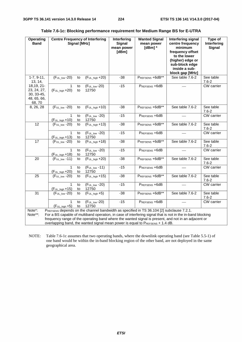
ETSI
ETSI TS 136 141 V14.3.0 (2017-04)2243GPP TS 36.141 version 14.3.0 Release 14
Table 7.6-1c: Blocking performance requirement for Medium Range BS for E-UTRA
Operating Band
Centre Frequency of Interfering Signal [MHz]
Interfering Signal
mean power [dBm]
Wanted Signal mean power
[dBm] *
Interfering signal centre frequency
minimum frequency offset
to the lower (higher) edge or sub-block edge
inside a sub-block gap [MHz]
Type of Interfering
Signal
1-7, 9-11, 13, 14,
18,19, 21-23, 24, 27, 30, 33-45, 48, 65, 66,
68, 70
(FUL_low -20) to (FUL_high +20) -38 PREFSENS +6dB** See table 7.6-2 See table 7.6-2
1 (FUL_high +20)
to to
(FUL_low -20) 12750
-15 PREFSENS +6dB ⎯ CW carrier
8, 26, 28 (FUL_low -20) to (FUL_high +10) -38 PREFSENS +6dB** See table 7.6-2 See table 7.6-2
1 (FUL_high +10)
to to
(FUL_low -20) 12750
-15 PREFSENS +6dB ⎯ CW carrier
12 (FUL_low -20) to (FUL_high +13) -38 PREFSENS +6dB** See table 7.6-2 See table 7.6-2
1 (FUL_high +13)
to to
(FUL_low -20) 12750
-15 PREFSENS +6dB ⎯ CW carrier
17 (FUL_low -20) to (FUL_high +18) -38 PREFSENS +6dB** See table 7.6-2 See table 7.6-2
1 (FUL_high +18)
to to
(FUL_low -20) 12750
-15 PREFSENS +6dB ⎯ CW carrier
20 (FUL_low -11) to (FUL_high +20) -38 PREFSENS +6dB** See table 7.6-2 See table 7.6-2
1 (FUL_high +20)
to to
(FUL_low -11) 12750
-15 PREFSENS +6dB ⎯ CW carrier
25 (FUL_low -20) to (FUL_high +15) -38 PREFSENS +6dB** See table 7.6-2 See table 7.6-2
1 (FUL_high +15)
to to
(FUL_low -20) 12750
-15 PREFSENS +6dB ⎯ CW carrier
31 (FUL_low -20) to (FUL_high +5) -38 PREFSENS +6dB** See table 7.6-2 See table 7.6-2
1 (FUL_high +5)
to to
(FUL_low -20) 12750
-15 PREFSENS +6dB ⎯ CW carrier
Note*: PREFSENS depends on the channel bandwidth as specified in TS 36.104 [2] subclause 7.2.1. Note**: For a BS capable of multiband operation, in case of interfering signal that is not in the in-band blocking
frequency range of the operating band where the wanted signal is present, and not in an adjacent or overlapping band, the wanted signal mean power is equal to PREFSENS + 1.4 dB.
NOTE: Table 7.6-1c assumes that two operating bands, where the downlink operating band (see Table 5.5-1) of one band would be within the in-band blocking region of the other band, are not deployed in the same geographical area.

ETSI
ETSI TS 136 141 V14.3.0 (2017-04)2253GPP TS 36.141 version 14.3.0 Release 14
Table 7.6.1d: Blocking performance requirement for Wide Area BS for NB-IoT standalone operation
Operating Band
Centre Frequency of Interfering Signal [MHz]
Interfering Signal
mean power [dBm]
Wanted Signal mean power
[dBm]
Interfering signal centre frequency
minimum frequency offset
from the lower/upper
Base Station RF Bandwidth edge
or sub-block edge inside a sub-block gap
[MHz]
Type of Interfering
Signal
1-3, 5, 11, 13,18,19, 26, 66, 70
(FUL_low -20) to (FUL_high +20) -43 PREFSENS +6dB* See table 7.6.2a See table 7.6. 2a
1 (FUL_high +20)
to to
(FUL_low -20) 12750
-15** PREFSENS +6dB* ⎯ CW carrier
8, 26, 28 (FUL_low -20) to (FUL_high +10) -43 PREFSENS +6dB* See table 7.6.2a See table 7.6. 2a
1 (FUL_high +10)
to to
(FUL_low -20) 12750
-15** PREFSENS +6dB* ⎯ CW carrier
12 (FUL_low -20) to (FUL_high +13) -43 PREFSENS +6dB* See table 7.6. 2a See table 7.6. 2a
1 (FUL_high +13)
to to
(FUL_low -20) 12750
-15** PREFSENS +6dB* ⎯ CW carrier
17 (FUL_low -20) to (FUL_high +18) -43 PREFSENS +6dB* See table 7.6. 2a See table 7.6. 2a
1 (FUL_high +18)
to to
(FUL_low -20) 12750
-15** PREFSENS +6dB* ⎯ CW carrier
20 (FUL_low -11) to (FUL_high +20) -43 PREFSENS +6dB* See table 7.6. 2a See table 7.6. 2a
1 (FUL_high +20)
to to
(FUL_low -11) 12750
-15** PREFSENS +6dB* ⎯ CW carrier
25 (FUL_low -20) to (FUL_high +15) -43 PREFSENS +6dB See table 7.6-2 See table 7.6-2
1 (FUL_high +15)
to
(FUL_low -20) 12750
-15 PREFSENS +6dB ⎯ CW carrier
31 (FUL_low -20) to (FUL_high +5) -43 PREFSENS +6dB See table 7.6-2 See table 7.6-2
1 (FUL_high +5)
to to
(FUL_low -20) 12750
-15 PREFSENS +6dB ⎯ CW carrier
Note*: PREFSENS is specified in TS 36.104 [2] subclause 7.2.1 Note**: Up to 24 exceptions are allowed for spurious response frequencies in each wanted signal frequency when
measured using a 1MHz step size. For these exceptions the above throughput requirement shall be met when the blocking signal is set to a level of -40 dBm for 15 kHz subcarrier spacing and -46 dBm for 3.75 kHz subcarrier spacing. In addition, each group of exceptions shall not exceed three contiguous measurements using a 1MHz step size.
NOTE: Table 7.6.1d assumes that two operating bands, where the downlink operating band (see Table 5.5-1) of one band would be within the in-band blocking region of the other band, are not deployed in the same geographical area.

ETSI
ETSI TS 136 141 V14.3.0 (2017-04)2263GPP TS 36.141 version 14.3.0 Release 14
Table 7.6.1e: Blocking performance requirement for Wide Area BS for E-UTRA with NB-IoT in-band/guard band operation
Operating Band
Centre Frequency of Interfering Signal [MHz]
Interfering Signal
mean power [dBm]
Wanted Signal mean power
[dBm]
Interfering signal centre frequency
minimum frequency offset
from the lower/upper
Base Station RF Bandwidth edge
or sub-block edge inside a sub-block gap
[MHz]
Type of Interfering
Signal
1-3, 5, 11, 13,18,19, 26, 66, 70
(FUL_low -20) to (FUL_high +20) -43 PREFSENS +6dB* See table 7.6.2 See table 7.6.2
1 (FUL_high +20)
to to
(FUL_low -20) 12750
-15*** PREFSENS +6dB* ⎯ CW carrier
8, 26, 28 (FUL_low -20) to (FUL_high +10) -43 PREFSENS +6dB* See table 7.6.2 See table 7.6.2
1 (FUL_high +10)
to to
(FUL_low -20) 12750
-15*** PREFSENS +6dB* ⎯ CW carrier
12 (FUL_low -20) to (FUL_high +13) -43 PREFSENS +6dB* See table 7.6.2 See table 7.6.2
1 (FUL_high +13)
to to
(FUL_low -20) 12750
-15*** PREFSENS +6dB* ⎯ CW carrier
17 (FUL_low -20) to (FUL_high +18) -43 PREFSENS +6dB* See table 7.6.2 See table 7.6.2
1 (FUL_high +18)
to to
(FUL_low -20) 12750
-15*** PREFSENS +6dB* ⎯ CW carrier
20 (FUL_low -11) to (FUL_high +20) -43 PREFSENS +6dB* See table 7.6.2 See table 7.6.2
1 (FUL_high +20)
to to
(FUL_low -11) 12750
-15*** PREFSENS +6dB* ⎯ CW carrier
25 (FUL_low -20) to (FUL_high +15) -43 PREFSENS +6dB See table 7.6-2 See table 7.6-2
1 (FUL_high +15)
to
(FUL_low -20) 12750
-15 PREFSENS +6dB ⎯ CW carrier
31 (FUL_low -20) to (FUL_high +5) -43 PREFSENS +6dB See table 7.6-2 See table 7.6-2
1 (FUL_high +5)
to to
(FUL_low -20) 12750
-15 PREFSENS +6dB ⎯ CW carrier
Note*: PREFSENS depends on the channel bandwidth or supported subcarrier spacing as specified in TS 36.104 [2] subclause 7.2.1.
Note**: For a BS capable of multiband operation, in case of interfering signal that is not in the in-band blocking frequency range of the operating band where the wanted signal is present, the wanted signal mean power is equal to PREFSENS + 1.4 dB.
Note***: For NB-IoT, up to 24 exceptions are allowed for spurious response frequencies in each wanted signal frequency when measured using a 1MHz step size. For these exceptions the above throughput requirement shall be met when the blocking signal is set to a level of -40 dBm for 15 kHz subcarrier spacing and -46 dBm for 3.75 kHz subcarrier spacing. In addition, each group of exceptions shall not exceed three contiguous measurements using a 1MHz step size.
NOTE: Table 7.6.1e assumes that two operating bands, where the downlink operating band (see Table 5.5-1) of one band would be within the in-band blocking region of the other band, are not deployed in the same geographical area.

ETSI
ETSI TS 136 141 V14.3.0 (2017-04)2273GPP TS 36.141 version 14.3.0 Release 14
Table 7.6-2: Interfering signals for blocking performance requirement
E-UTRA channel BW of the
lowest/highest carrier received
[MHz]
Interfering signal centre frequency minimum offset to the
lower/upper Base Station RF Bandwidth edge or sub-block
edge inside a sub-block gap [MHz]
Type of interfering signal
1.4 ±2.1 1.4MHz E-UTRA signal 3 ±4.5 3MHz E-UTRA signal 5 ±7.5 5MHz E-UTRA signal
10 ±7.5 5MHz E-UTRA signal 15 ±7.5 5MHz E-UTRA signal 20 ±7.5 5MHz E-UTRA signal
Table 7.6.2a: Interfering signals for blocking performance requirement for NB-IoT standalone operation
NB-IoT channel BW of the
lowest/highest carrier received
[MHz]
Interfering signal centre frequency minimum offset to the lower/upper Base Station RF Bandwidth edge or sub-block edge inside a sub-block
gap [MHz]
Type of interfering signal
0.2 ±7.5 5MHz E-UTRA signal
Table 7.6-2b: Interfering signals for blocking performance requirement for E-UTRA with NB-IoT in-band/guard band operation
E-UTRA channel BW of the
lowest/highest carrier received
[MHz]
Interfering signal centre frequency minimum offset to the lower/upper Base Station RF Bandwidth edge or sub-block edge inside a sub-
block gap [MHz]
Type of interfering signal
1.4 ±2.1 1.4MHz E-UTRA signal 3 ±4.5 3MHz E-UTRA signal 5 ±7.5 5MHz E-UTRA signal
10 ±7.5 5MHz E-UTRA signal 15 ±7.5 5MHz E-UTRA signal 20 ±7.5 5MHz E-UTRA signal
NOTE: If the above Test Requirement differs from the Minimum Requirement then the Test Tolerance applied for this test is non-zero. The relationship between Minimum Requirements and Test Requirements is defined in subclause 4.1 and the explanation of how the Minimum Requirement has been relaxed by the Test Tolerance is given in Annex G.
7.6.5.2 Co-location with other base stations
This additional blocking requirement may be applied for the protection of E-UTRA BS or NB-IoT receivers when GSM, CMDA, UTRA or E-UTRA BS operating in a different frequency band are co-located with an E-UTRA or NB-IoT BS. The requirement is applicable to all channel bandwidths supported by the E-UTRA BS.
The requirements in this clause assume a 30 dB coupling loss between interfering transmitter and E-UTRA or NB-IoT BS receiver and are based on co-location with base stations of the same class.
For each measured E-UTRA carrier, the throughput shall be ≥ 95% of the maximum throughput of the reference measurement channel, with a wanted and an interfering signal coupled to BS antenna input using the parameters in Table 7.6-3 for Wide Area BS, in Table 7.6-4 for Local Area BS and in Table 7.6-5 for Medium Range BS. The reference measurement channel for the wanted signal is specified in Tables 7.2-1, 7.2-2 and 7.2-4 for each channel bandwidth and further specified in Annex A.
For each measured NB-IoT carrier, the throughput shall be ≥ 95% of the maximum throughput of the reference measurement channel, with a wanted and an interfering signal coupled to BS antenna input using the parameters in

ETSI
ETSI TS 136 141 V14.3.0 (2017-04)2283GPP TS 36.141 version 14.3.0 Release 14
Table 7.6-3 for Wide Area BS. The reference measurement channel for the wanted signal is specified in Tables 7.2-5 for each channel sub-carrier spacing option and further specified in Annex A.
Table 7.6-3: Blocking performance requirement for E-UTRA and NB-IoT Wide Area BS when co-located with BS in other frequency bands.
Co-located BS type Centre Frequency of
Interfering Signal (MHz)
Interfering Signal mean
power (dBm)
Wanted Signal mean power (dBm)
Type of Interfering
Signal
Macro GSM850 or CDMA850 869 – 894 +16** PREFSENS + 6dB* CW carrier
Macro GSM900 921 – 960 +16** PREFSENS + 6dB* CW carrier Macro DCS1800 1805 – 1880 +16** PREFSENS + 6dB* CW carrier Macro PCS1900 1930 – 1990 +16** PREFSENS + 6dB* CW carrier WA UTRA FDD Band I or E-UTRA Band 1 2110 – 2170 +16** PREFSENS + 6dB* CW carrier
WA UTRA FDD Band II or E-UTRA Band 2 1930 – 1990 +16** PREFSENS + 6dB* CW carrier
WA UTRA FDD Band III or E-UTRA Band 3 1805 – 1880 +16** PREFSENS + 6dB* CW carrier
WA UTRA FDD Band IV or E-UTRA Band 4 2110 – 2155 +16** PREFSENS + 6dB* CW carrier
WA UTRA FDD Band V or E-UTRA Band 5 869 – 894 +16** PREFSENS + 6dB* CW carrier
WA UTRA FDD Band VI or E-UTRA Band 6 875 – 885 +16** PREFSENS + 6dB* CW carrier
WA UTRA FDD Band VII or E-UTRA Band 7 2620 – 2690 +16** PREFSENS + 6dB* CW carrier
WA UTRA FDD Band VIII or E-UTRA Band 8 925 – 960 +16** PREFSENS + 6dB* CW carrier
WA UTRA FDD Band IX or E-UTRA Band 9 1844.9 – 1879.9 +16** PREFSENS + 6dB* CW carrier
WA UTRA FDD Band X or E-UTRA Band 10 2110 – 2170 +16** PREFSENS + 6dB* CW carrier
WA UTRA FDD Band XI or E-UTRA Band 11 1475.9 –1495.9 +16** PREFSENS + 6dB* CW carrier
WA UTRA FDD Band XII or E-UTRA Band 12 729 - 746 +16** PREFSENS + 6dB* CW carrier
WA UTRA FDD Band XIIII or E-UTRA Band 13 746 - 756 +16** PREFSENS + 6dB* CW carrier
WA UTRA FDD Band XIV or E-UTRA Band 14
758 - 768 +16** PREFSENS + 6dB* CW carrier
WA E-UTRA Band 17 734 - 746 +16** PREFSENS + 6dB* CW carrier WA E-UTRA Band 18 860 - 875 +16** PREFSENS + 6dB* CW carrier WA UTRA FDD Band XIX or E-UTRA Band 19 875 - 890 +16** PREFSENS + 6dB* CW carrier
WA UTRA FDD Band XX or E-UTRA Band 20 791 - 821 +16** PREFSENS + 6dB* CW carrier
WA E-UTRA Band 24 1525 – 1559 +16** PREFSENS + 6dB* CW carrier WA UTRA FDD Band XXI or E-UTRA Band 21 1495.9 – 1510.9 +16** PREFSENS + 6dB* CW carrier
WA UTRA FDD Band XXII or E-UTRA Band 22 3510 – 3590 +16** PREFSENS + 6dB* CW carrier
WA E-UTRA Band 23 2180-2200 +16** PREFSENS + 6dB* CW carrier WA UTRA FDD Band XXV or E-UTRA Band 25
1930 – 1995 +16** PREFSENS + 6dB* CW carrier
WA UTRA FDD Band XXVI or E-UTRA Band 26 859 – 894 +16** PREFSENS + 6dB* CW carrier
WA E-UTRA Band 27 852 - 869 +16** PREFSENS + 6dB* CW carrier WA E-UTRA Band 28 758 – 803 +16** PREFSENS + 6dB* CW carrier WA E-UTRA Band 29 717 – 728 +16** PREFSENS + 6dB* CW carrier WA E-UTRA Band 30 2350 – 2360 +16** PREFSENS + 6dB* CW carrier
WA E-UTRA Band 31 462.5 – 467.5 +16** PREFSENS + 6dB* CW carrier

ETSI
ETSI TS 136 141 V14.3.0 (2017-04)2293GPP TS 36.141 version 14.3.0 Release 14
WA UTRA FDD Band XXXII or E-UTRA Band 32
1452-1496 (NOTE 3) +16** PREFSENS + 6dB* CW carrier
WA UTRA TDD Band a) or E-UTRA in Band 33 1900-1920 +16** PREFSENS + 6dB* CW carrier
WA UTRA TDD Band a) or E-UTRA in Band 34 2010-2025 +16** PREFSENS + 6dB* CW carrier
WA UTRA TDD Band b) or E-UTRA in Band 35
1850-1910 +16** PREFSENS + 6dB* CW carrier
WA UTRA TDD Band b) or E-UTRA in Band 36 1930-1990 +16** PREFSENS + 6dB* CW carrier
WA UTRA TDD Band c) or E-UTRA Band 37 1910-1930 +16** PREFSENS + 6dB* CW carrier
WA UTRA TDD Band d) or E-UTRA Band 38 2570-2620 +16** PREFSENS + 6dB* CW carrier
WA UTRA TDD Band f) or E-UTRA Band 39 1880-1920 +16** PREFSENS + 6dB* CW carrier
WA UTRA TDD Band e) or E-UTRA Band 40 2300-2400 +16** PREFSENS + 6dB* CW carrier
WA E-UTRA Band 41 2496-2690 +16** PREFSENS + 6dB* CW carrier WA E-UTRA Band 42 3400 - 3600 +16** PREFSENS + 6dB* CW carrier WA E-UTRA Band 43 3600 - 3800 +16** PREFSENS + 6dB* CW carrier WA E-UTRA Band 44 703-803 +16** PREFSENS + 6dB* CW carrier WA E-UTRA Band 45 1447-1467 +16** PREFSENS + 6dB* CW carrier WA E-UTRA Band 48 3550-3700 +16 PREFSENS + 6dB* CW carrier WA E-UTRA Band 65 2110 – 2200 +16** PREFSENS + 6dB* CW carrier WA E-UTRA Band 66 2110 – 2200 +16** PREFSENS + 6dB* CW carrier WA E-UTRA Band 67 738-758 +16** PREFSENS + 6dB* CW carrier WA E-UTRA Band 68 753-783 +16** PREFSENS + 6dB* CW carrier WA E-UTRA Band 69 2570-2620 +16** PREFSENS + 6dB* CW carrier WA E-UTRA Band 70 1995-2020 +16** PREFSENS + 6dB* CW carrier Note*: PREFSENS is related to the channel bandwidth and specified in TS 36.104 [2] subclause
7.2.1. Note**: For NB-IoT, up to 24 exceptions are allowed for spurious response frequencies in each
wanted signal frequency when measured using a 1MHz step size. For these exceptions the above throughput requirement shall be met when the blocking signal is set to a level of -40 dBm for 15 kHz subcarrier spacing and -46 dBm for 3.75 kHz subcarrier spacing. In addition, each group of exceptions shall not exceed three contiguous measurements using a 1MHz step size.
NOTE 1: Except for a BS operating in Band 13, these requirements do not apply when the interfering signal falls within any of the supported uplink operating band or in the 10 MHz immediately outside any of the supported uplink operating band. For a BS operating in band 13 the requirements do not apply when the interfering signal falls within the frequency range 768-797 MHz.
NOTE 2: Some combinations of bands may not be possible to co-site based on the requirements above. The current state-of-the-art technology does not allow a single generic solution for co-location of UTRA TDD or E-UTRA TDD with E-UTRA FDD on adjacent frequencies for 30dB BS-BS minimum coupling loss. However, there are certain site-engineering solutions that can be used. These techniques are addressed in TR 25.942 [11].
NOTE 3: For a BS operating in band 11 or 21, this requirement applies for interfering signal within the frequency range 1475.9-1495.9 MHz.
NOTE 4: Co-located TDD base stations that are synchronized and using the same or adjacent operating band can receive without special co-location requirements. For unsynchronized base stations, special co-location requirements may apply that are not covered by the 3GPP specifications.
Table 7.6-4: Blocking performance requirement for Local Area BS when co-located with BS in other frequency bands.
Co-located BS type Centre Frequency of
Interfering Signal (MHz)
Interfering Signal mean
power (dBm)
Wanted Signal mean power (dBm)
Type of Interfering
Signal
Pico GSM850 869 – 894 -7 PREFSENS + 6dB* CW carrier Pico GSM900 921 – 960 -7 PREFSENS + 6dB* CW carrier Pico DCS1800 1805 – 1880 -4 PREFSENS + 6dB* CW carrier Pico PCS1900 1930 – 1990 -4 PREFSENS + 6dB* CW carrier

ETSI
ETSI TS 136 141 V14.3.0 (2017-04)2303GPP TS 36.141 version 14.3.0 Release 14
LA UTRA FDD Band I or E-UTRA Band 1 2110 – 2170 -6 PREFSENS + 6dB* CW carrier
LA UTRA FDD Band II or E-UTRA Band 2 1930 – 1990 -6 PREFSENS + 6dB* CW carrier
LA UTRA FDD Band III or E-UTRA Band 3 1805 – 1880 -6 PREFSENS + 6dB* CW carrier
LA UTRA FDD Band IV or E-UTRA Band 4 2110 – 2155 -6 PREFSENS + 6dB* CW carrier
LA UTRA FDD Band V or E-UTRA Band 5 869 – 894 -6 PREFSENS + 6dB* CW carrier
LA UTRA FDD Band VI or E-UTRA Band 6 875 – 885 -6 PREFSENS + 6dB* CW carrier
LA UTRA FDD Band VII or E-UTRA Band 7 2620 – 2690 -6 PREFSENS + 6dB* CW carrier
LA UTRA FDD Band VIII or E-UTRA Band 8 925 – 960 -6 PREFSENS + 6dB* CW carrier
LA UTRA FDD Band IX or E-UTRA Band 9 1844.9 – 1879.9 -6 PREFSENS + 6dB* CW carrier
LA UTRA FDD Band X or E-UTRA Band 10 2110 – 2170 -6 PREFSENS + 6dB* CW carrier
LA UTRA FDD Band XI or E-UTRA Band 11 1475.9 - 1495.9 -6 PREFSENS + 6dB* CW carrier
LA UTRA FDD Band XII or E-UTRA Band 12 729 - 746 -6 PREFSENS + 6dB* CW carrier
LA UTRA FDD Band XIIII or E-UTRA Band 13 746 - 756 -6 PREFSENS + 6dB* CW carrier
LA UTRA FDD Band XIV or E-UTRA Band 14 758 - 768 -6 PREFSENS + 6dB* CW carrier
LA E-UTRA Band 17 734 - 746 -6 PREFSENS + 6dB* CW carrier LA E-UTRA Band 18 860 - 875 -6 PREFSENS + 6dB* CW carrier LA UTRA FDD Band XIX or E-UTRA Band 19 875 - 890 -6 PREFSENS + 6dB* CW carrier
LA UTRA FDD Band XX or E-UTRA Band 20 791 - 821 -6 PREFSENS + 6dB* CW carrier
LA UTRA FDD Band XXI or E-UTRA Band 21 1495.9 – 1510.9 -6 PREFSENS + 6dB* CW carrier
LA UTRA FDD Band XXII or E-UTRA Band 22 3510 – 3590 -6 PREFSENS + 6dB* CW carrier
LA E-UTRA Band 23 2180-2200 -6 PREFSENS + 6dB* CW carrier LA E-UTRA Band 24 1525 – 1559 -6 PREFSENS + 6dB* CW carrier LA UTRA FDD Band XXV or E-UTRA Band 25 1930 – 1995 -6 PREFSENS + 6dB* CW carrier
LA UTRA FDD Band XXVI or E-UTRA Band 26 859 – 894 -6 PREFSENS + 6dB* CW carrier
LA E-UTRA Band 27 852 - 869 -6 PREFSENS + 6dB* CW carrier LA E-UTRA Band 28 758 – 803 -6 PREFSENS + 6dB* CW carrier LA E-UTRA Band 29 717 – 728 -6 PREFSENS + 6dB* CW carrier LA E-UTRA Band 30 2350 – 2360 -6 PREFSENS + 6dB* CW carrier
LA E-UTRA Band 31 462.5 – 467.5 -6 PREFSENS + 6dB* CW carrier LA UTRA FDD Band XXXII or E-UTRA Band 32
1452-1496 (NOTE 3)
-6 PREFSENS + 6dB* CW carrier
LA UTRA TDD Band a) or E-UTRA Band 33 1900-1920 -6 PREFSENS + 6dB* CW carrier
LA UTRA TDD Band a) or E-UTRA Band 34 2010-2025 -6 PREFSENS + 6dB* CW carrier
LA UTRA TDD Band b) or E-UTRA Band 35
1850-1910
-6 PREFSENS + 6dB* CW carrier
LA UTRA TDD Band b) or E-UTRA Band 36 1930-1990 -6 PREFSENS + 6dB* CW carrier
LA UTRA TDD Band c) or E-UTRA Band 37 1910-1930 -6 PREFSENS + 6dB* CW carrier
LA UTRA TDD in Band d) or E-UTRA Band 38 2570-2620 -6 PREFSENS + 6dB* CW carrier
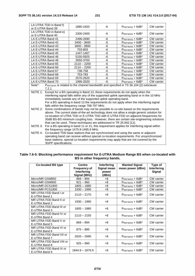
ETSI
ETSI TS 136 141 V14.3.0 (2017-04)2313GPP TS 36.141 version 14.3.0 Release 14
LA UTRA TDD in Band f) or E-UTRA Band 39 1880-1920 -6 PREFSENS + 6dB* CW carrier
LA UTRA TDD in Band e) or E-UTRA Band 40 2300-2400 -6 PREFSENS + 6dB* CW carrier
LA E-UTRA Band 41 2496-2690 -6 PREFSENS + 6dB* CW carrier LA E-UTRA Band 42 3400 - 3600 -6 PREFSENS + 6dB* CW carrier LA E-UTRA Band 43 3600 - 3800 -6 PREFSENS + 6dB* CW carrier LA E-UTRA Band 44 703-803 -6 PREFSENS + 6dB* CW carrier LA E-UTRA Band 45 1447-1467 -6 PREFSENS + 6dB* CW carrier LA E-UTRA Band 46 5150-5925 -6 PREFSENS + 6dB* CW carrier LA E-UTRA Band 48 3550-3700 -6 PREFSENS + 6dB* CW carrier LA E-UTRA Band 65 2110 – 2200 -6 PREFSENS + 6dB* CW carrier LA E-UTRA Band 66 2110 – 2200 -6 PREFSENS + 6dB* CW carrier LA E-UTRA Band 67 738-758 -6 PREFSENS + 6dB* CW carrier LA E-UTRA Band 68 753-783 -6 PREFSENS + 6dB* CW carrier LA E-UTRA Band 69 2570-2620 -6 PREFSENS + 6dB* CW carrier LA E-UTRA Band 70 1995-2020 -6 PREFSENS + 6dB* CW carrier Note*: PREFSENS is related to the channel bandwidth and specified in TS 36.104 [2] subclause
7.2.1. NOTE 1: Except for a BS operating in Band 13, these requirements do not apply when the
interfering signal falls within any of the supported uplink operating band or in the 10 MHz immediately outside any of the supported uplink operating band. For a BS operating in band 13 the requirements do not apply when the interfering signal falls within the frequency range 768-797 MHz.
NOTE 2: Some combinations of bands may not be possible to co-site based on the requirements above. The current state-of-the-art technology does not allow a single generic solution for co-location of UTRA TDD or E-UTRA TDD with E-UTRA FDD on adjacent frequencies for 30dB BS-BS minimum coupling loss. However, there are certain site-engineering solutions that can be used. These techniques are addressed in TR 25.942 [11].
NOTE 3: For a BS operating in band 11 or 21, this requirement applies for interfering signal within the frequency range 1475.9-1495.9 MHz.
NOTE 4: Co-located TDD base stations that are synchronized and using the same or adjacent operating band can receive without special co-location requirements. For unsynchronized base stations, special co-location requirements may apply that are not covered by the 3GPP specifications.
Table 7.6-5: Blocking performance requirement for E-UTRA Medium Range BS when co-located with BS in other frequency bands.
Co-located BS type Centre Frequency of
Interfering Signal (MHz)
Interfering Signal mean
power (dBm)
Wanted Signal mean power (dBm)
Type of Interfering
Signal
Micro/MR GSM850 869 – 894 +8 PREFSENS + 6dB* CW carrier Micro/MR GSM900 921 – 960 +8 PREFSENS + 6dB* CW carrier Micro/MR DCS1800 1805 – 1880 +8 PREFSENS + 6dB* CW carrier Micro/MR PCS1900 1930 – 1990 +8 PREFSENS + 6dB* CW carrier MR UTRA FDD Band I or E-UTRA Band 1
2110 – 2170 +8 PREFSENS + 6dB* CW carrier
MR UTRA FDD Band II or E-UTRA Band 2 1930 – 1990 +8 PREFSENS + 6dB* CW carrier
MR UTRA FDD Band III or E-UTRA Band 3 1805 – 1880 +8 PREFSENS + 6dB* CW carrier
MR UTRA FDD Band IV or E-UTRA Band 4
2110 – 2155 +8 PREFSENS + 6dB* CW carrier
MR UTRA FDD Band V or E-UTRA Band 5 869 – 894 +8 PREFSENS + 6dB* CW carrier
MR UTRA FDD Band VI or E-UTRA Band 6 875 – 885 +8 PREFSENS + 6dB* CW carrier
MR UTRA FDD Band VII or E-UTRA Band 7 2620 – 2690 +8 PREFSENS + 6dB* CW carrier
MR UTRA FDD Band VIII or E-UTRA Band 8 925 – 960 +8 PREFSENS + 6dB* CW carrier
MR UTRA FDD Band IX or E-UTRA Band 9 1844.9 – 1879.9 +8 PREFSENS + 6dB* CW carrier

ETSI
ETSI TS 136 141 V14.3.0 (2017-04)2323GPP TS 36.141 version 14.3.0 Release 14
MR UTRA FDD Band X or E-UTRA Band 10 2110 – 2170 +8 PREFSENS + 6dB* CW carrier
MR UTRA FDD Band XI or E-UTRA Band 11 1475.9 –1495.9 +8 PREFSENS + 6dB* CW carrier
MR UTRA FDD Band XII or E-UTRA Band 12 729 - 746 +8 PREFSENS + 6dB* CW carrier
MR UTRA FDD Band XIIII or E-UTRA Band 13 746 - 756 +8 PREFSENS + 6dB* CW carrier
MR UTRA FDD Band XIV or E-UTRA Band 14 758 - 768 +8 PREFSENS + 6dB* CW carrier
MR E-UTRA Band 17 734 - 746 +8 PREFSENS + 6dB* CW carrier MR E-UTRA Band 18 860 - 875 +8 PREFSENS + 6dB* CW carrier MR UTRA FDD Band XIX or E-UTRA Band 19 875 - 890 +8 PREFSENS + 6dB* CW carrier
MR UTRA FDD Band XX or E-UTRA Band 20
791 - 821 +8 PREFSENS + 6dB* CW carrier
MR UTRA FDD Band XXI or E-UTRA Band 21 1495.9 – 1510.9 +8 PREFSENS + 6dB* CW carrier
MR UTRA FDD Band XXII or E-UTRA Band 22 3510 – 3590 +8 PREFSENS + 6dB* CW carrier
MR E-UTRA Band 23 2180 - 2200 +8 PREFSENS + 6dB* CW carrier MR E-UTRA Band 24 1525 – 1559 +8 PREFSENS + 6dB* CW carrier MR UTRA FDD Band XXV or E-UTRA Band 25 1930 – 1995 +8 PREFSENS + 6dB* CW carrier
MR UTRA FDD Band XXVI or E-UTRA Band 26 859 – 894 +8 PREFSENS + 6dB* CW carrier
MR E-UTRA Band 27 852 - 869 +8 PREFSENS + 6dB* CW carrier MR E-UTRA Band 28 758 – 803 +8 PREFSENS + 6dB* CW carrier MR E-UTRA Band 29 717 – 728 +8 PREFSENS + 6dB* CW carrier MR E-UTRA Band 30 2350 – 2360 +8 PREFSENS + 6dB* CW carrier
MR E-UTRA Band 31 462.5 – 467.5 +8 PREFSENS + 6dB* CW carrier MR UTRA FDD Band XXXII or E-UTRA Band 32
1452-1496 (NOTE 3) +8 PREFSENS + 6dB* CW carrier
MR E-UTRA Band 33 1900-1920 +8 PREFSENS + 6dB* CW carrier MR E-UTRA Band 34 2010-2025 +8 PREFSENS + 6dB* CW carrier MR E-UTRA Band 35 1850-1910
+8 PREFSENS + 6dB* CW carrier
MR E-UTRA Band 36 1930-1990 +8 PREFSENS + 6dB* CW carrier MR E-UTRA Band 37 1910-1930 +8 PREFSENS + 6dB* CW carrier MR E-UTRA Band 38 2570-2620 +8 PREFSENS + 6dB* CW carrier MR E-UTRA Band 39 1880-1920 +8 PREFSENS + 6dB* CW carrier MR E-UTRA Band 40 2300-2400 +8 PREFSENS + 6dB* CW carrier MR E-UTRA Band 41 2496 - 2690 +8 PREFSENS + 6dB* CW carrier MR E-UTRA Band 42 3400-3600 +8 PREFSENS + 6dB* CW carrier MR E-UTRA Band 43 3600-3800 +8 PREFSENS + 6dB* CW carrier MR E-UTRA Band 44 703-803 +8 PREFSENS + 6dB* CW carrier MR E-UTRA Band 45 1447-1467 +8 PREFSENS + 6dB* CW carrier MR E-UTRA Band 46 5150-5925 +8 PREFSENS + 6dB* CW carrier MR E-UTRA Band 48 3550-3700 +8 PREFSENS + 6dB* CW carrier MR E-UTRA Band 65 2110 – 2200 +8 PREFSENS + 6dB* CW carrier

ETSI
ETSI TS 136 141 V14.3.0 (2017-04)2333GPP TS 36.141 version 14.3.0 Release 14
MR E-UTRA Band 66 2110 – 2200 +8 PREFSENS + 6dB* CW carrier MR E-UTRA Band 67 738-758 +8 PREFSENS + 6dB* CW carrier MR E-UTRA Band 69 2570-2620 +8 PREFSENS + 6dB* CW carrier MR E-UTRA Band 70 1695-1710 +8 PREFSENS + 6dB* CW carrier MR E-UTRA Band 68 753-783 +8 PREFSENS + 6dB* CW carrier Note*: PREFSENS is related to the channel bandwidth and specified in TS 36.104 [2] subclause
7.2.1. NOTE 1: Except for a BS operating in Band 13, these requirements do not apply when the
interfering signal falls within any of the supported uplink operating band or in the 10 MHz immediately outside any of the supported uplink operating band. For a BS operating in band 13 the requirements do not apply when the interfering signal falls within the frequency range 768-797 MHz.
NOTE 2: Some combinations of bands may not be possible to co-site based on the requirements above. The current state-of-the-art technology does not allow a single generic solution for co-location of UTRA TDD or E-UTRA TDD with E-UTRA FDD on adjacent frequencies for 30dB BS-BS minimum coupling loss. However, there are certain site-engineering solutions that can be used. These techniques are addressed in TR 25.942 [11].
NOTE 3: For a BS operating in band 11 or 21, this requirement applies for interfering signal within the frequency range 1475.9-1495.9 MHz.
NOTE 4: Co-located TDD base stations that are synchronized and using the same or adjacent operating band can receive without special co-location requirements. For unsynchronized base stations, special co-location requirements may apply that are not covered by the 3GPP specifications.
7.7 Receiver spurious emissions
7.7.1 Definition and applicability
The spurious emissions power is the power of emissions generated or amplified in a receiver that appear at the BS receiver antenna connector. The requirements apply to all BS with separate RX and TX antenna ports. The test shall be performed when both TX and RX are on, with the TX port terminated.
For TDD BS with common RX and TX antenna port the requirement applies during the Transmitter OFF period. For FDD BS with common RX and TX antenna port the transmitter spurious emission as specified in clause 6.6.4 is valid.
For BS capable of multi-band operation where multiple bands are mapped on separate antenna connectors, the single-band requirements apply and the excluded frequency range is only applicable for the operating band supported on each antenna connector.
Unless otherwise stated, a BS declared to be capable of E-UTRA with NB-IoT in-band and guard band operations is only required to pass the receiver spurious emissions tests for E-UTRA with guard band operation; it is not required to perform the receiver spurious emissions tests again for E-UTRA with in-band operation.
7.7.2 Minimum Requirements
The minimum requirement is in TS 36.104 [2] subclause 7.7.1.
7.7.3 Test purpose
The test purpose is to verify the ability of the BS to limit the interference caused by receiver spurious emissions to other systems.
7.7.4 Method of test
7.7.4.1 Initial conditions
Test environment: normal; see subclause D.2.
RF channels to be tested for single carrier: M, see subclause 4.7.
ETSI
ETSI TS 136 141 V14.3.0 (2017-04)2343GPP TS 36.141 version 14.3.0 Release 14
Base Station RF Bandwidth edge positions to be tested for multi-carrier and/or CA: MRFBW in single-band operation, see subclause 4.7.1; BRFBW_T’RFBW and B’RFBW_TRFBW in multi-band operation, see subclause 4.7.1.
1) Connect a measurement receiver to the BS antenna connector as shown in Annex I.2.6.
2) Enable the BS receiver.
3) Terminate the BS Tx antenna connector as shown in Annex I.2.6.
7.7.4.2 Procedure
1) For a E-UTRA FDD FDD BS declared to be capable of single carrier operation only, start BS transmission according to E-TM 1.1 at manufacturer’s declared rated output power.
For a E-UTRA FDD FDD BS declared to be capable of multi-carrier and/or CA operation, set the BS to transmit according to E-TM 1.1 on all carriers configured using the applicable test configuration and corresponding power setting specified in sub-clause 4.10 and 4.11
For E-UTRA BS declared to be capable of NB-IoT in-band or guard band operation single carrier operation only, start BS transmission according to E-TM 1.1. and N-TM at manufacturer’s declared rated output power.
For a E-UTRA BS declared to be capable of NB-IoT in-band or guard band operation multi-carrier, set the BS to transmit according to E-TM 1.1 on all E-UTRA carriers and to N-TM on all NB-IoT carriers configured using the applicable test configuration and corresponding power setting specified in sub-clause 4.10 and 4.11.
For a BS declared to be capable of NB-IoT standalone single carrier operation only, start BS transmission according to N-TM at manufacturer’s declared rated output power.
For a BS declared to be capable of NB-IoT standalone multi-carrier operation, set the BS to transmit according to N-TM on all carriers configured using the applicable test configuration and corresponding power setting specified in sub-clause 4.10 and 4.11
For a E-UTRA and NB-IoT standalone BS, set the BS to transmit according to E-TM 1.1 on all E-UTRA carriers and according to N-TM on all NB-IoT carriers configured using the applicable test configuration and corresponding power setting specified in sub-clause 4.10 and 4.11
2) Set measurement equipment parameters as specified in table 7.7-1.
3) Measure the spurious emissions over each frequency range described in subclause 7.7.5.
4) Repeat the test for the Rx port(s), which was (were) terminated.
In addition, for a multi-band capable BS, the following step shall apply:
5) For multi-band capable BS and single band tests, repeat the steps above per involved band where single band test configurations and test models shall apply with no carrier activated in the other band. For multi-band capable BS with separate antenna connector, the antenna connector not being under test in case of single-band or multi-band test shall be terminated.
7.7.5 Test requirements
The power of any spurious emission shall not exceed the levels in Table 7.7-1.
In addition to the requirements in Table 7.7-1, the power of any spurious emission shall not exceed the levels specified for Protection of the E-UTRA FDD BS receiver of own or different BS in Clause 6.6.4.5.3 and for Co-existence with other systems in the same geographical area in Clause 6.6.4.5.4. In addition, the co-existence requirements for co-located base stations specified in subclause 6.6.4.5.5 may also be applied.

ETSI
ETSI TS 136 141 V14.3.0 (2017-04)2353GPP TS 36.141 version 14.3.0 Release 14
Table 7.7-1: General spurious emission test requirement
Frequency range Maximum level
Measurement Bandwidth
Note
30MHz - 1 GHz -57 dBm 100 kHz 1 GHz - 12.75 GHz -47 dBm 1 MHz
12.75 GHz - 5th harmonic of the upper frequency
edge of the UL operating band in GHz
-47 dBm 1 MHz Applies only for Bands 22, 42, 43 and 48.
NOTE: The frequency range between 2.5 * BWChannel below the first carrier frequency and 2.5 * BWChannel above the last carrier frequency transmitted by the BS, where BWChannel is the channel bandwidth according to Table 5.6-1, may be excluded from the requirement. However, frequencies that are more than 10 MHz below the lowest frequency of any of the BS supported downlink operating band or more than 10 MHz above the highest frequency of any of the BS supported downlink operating band (see Table 5.5-1) shall not be excluded from the requirement.
For BS capable of multi-band operation, the excluded frequency range applies for all supported operating bands. For BS capable of multi-band operation where multiple bands are mapped on separate antenna connectors, the single-band requirements apply and the excluded frequency range is only applicable for the operating band supported on each antenna connector.
NOTE: If the above Test Requirement differs from the Minimum Requirement then the Test Tolerance applied for this test is non-zero. The relationship between Minimum Requirements and Test Requirements is defined in subclause 4.1 and the explanation of how the Minimum Requirement has been relaxed by the Test Tolerance is given in Annex G.
7.8 Receiver intermodulation
7.8.1 Definition and applicability
Third and higher order mixing of the two interfering RF signals can produce an interfering signal in the band of the desired channel. Intermodulation response rejection is a measure of the capability of the receiver to receive a wanted signal on its assigned channel frequency in the presence of two interfering signals which have a specific frequency relationship to the wanted signal. Interfering signals shall be a CW signal and an E-UTRA signal as specified in Annex C.
Unless otherwise stated, a BS declared to be capable of E-UTRA with NB-IoT in-band and guard band operations is only required to pass the receiver intermodulation tests for E-UTRA with guard band operation; it is not required to perform the receiver intermodulation tests again for E-UTRA with in-band operation.
7.8.2 Minimum Requirement
The minimum requirement is in TS 36.104 [2] subclause 7.8.1.
7.8.3 Test purpose
The test purpose is to verify the ability of the BS receiver to inhibit the generation of intermodulation products in its non-linear elements caused by the presence of two high-level interfering signals at frequencies with a specific relationship to the frequency of the wanted signal.
7.8.4 Method of test
7.8.4.1 Initial conditions
Test environment: normal; see subclause D.2.
RF channels to be tested for single carrier: B, M and T; see subclause 4.7.

ETSI
ETSI TS 136 141 V14.3.0 (2017-04)2363GPP TS 36.141 version 14.3.0 Release 14
Base Station RF Bandwidth edge positions to be tested for multi-carrier and/or CA: BRFBW and TRFBW in single-band operation, see subclause 4.7.1; BRFBW_T’RFBW and B’RFBW_TRFBW in multi-band operation, see subclause 4.7.1.
1) Set-up the measurement system as shown in Annex I.2.7.
7.8.4.2 Procedures
For E-UTRA and E-UTRA with NB-IoT in-band or guard band operation:
1) Generate the E-UTRA wanted signal using the applicable test configuration specified in subclause 4.10 and 4.11 and adjust the signal level to the BS under test to the level specified in Table 7.8-1.
For BS declared to be capable of NB-IoT in-band or guard band operation, generate the NB-IoT wanted signal using the applicable test configuration specified in subclause 4.10 and 4.11 and adjust the signal level to the BS under test to the level specified in Table 7.8-1a or Table 7.8-1b.
2) Adjust the signal generators to the type of interfering signals, levels and the frequency offsets as specified in Table 7.8-2 for intermodulation requirement and Table 7.8-3, Table 7.8-3a, Table 7.8-3b, Table 7.8-4, Table 7.8-5 and Table 7.8-6 for narrowband intermodulation requirement.
3) Adjust the signal generators to obtain the specified level of interfering signal at the BS input.
4) Measure the E-UTRA throughput according to Annex E, for multi-carrier and/or CA operation the throughput shall be measured for relevant carriers specified by the test configuration specified in subclause 4.10 and 4.11.
For BS declared to be capable of NB-IoT in-band or guard band operation, measure the NB-IoT throughput according to Annex E, for multi-carrier the throughput shall be measured for relevant carriers specified by the test configuration specified in subclause 4.10 and 4.11.
5) Repeat the test for the port(s) which was (were) terminated.
In addition, for a multi-band capable BS with separate antenna connectors, the following steps shall apply:
6) For single band tests, repeat the steps above per involved band where single band test configurations shall apply with no carrier activated in the other band.
Interfering signal shall first be applied on the same port as the wanted signal. The test shall be repeated with the interfering signal applied on the other port (if any) mapped to the same receiver as the wanted signal. Any antenna connector with no signal applied in case of single-band or multi-band test shall be terminated.
7) Repeat step 6) with the wanted signal for the other band(s) applied on the respective port(s).
For NB-IoT standalone operation:
1) Generate the NB-IoT wanted signal using the applicable test configuration specified in subclause 4.10 and 4.11 and adjust the signal level to the BS under test to the level specified in Table 7.8-1c.
2) Adjust the signal generators to the type of interfering signals, levels and the frequency offsets as specified in Table 7.8-2a for intermodulation requirement and Table 7.8-3c for narrowband intermodulation requirement.
3) Adjust the signal generators to obtain the specified level of interfering signal at the BS input.
4) Measure the NB-IoT throughput according to Annex E, for multi-carrier the throughput shall be measured for relevant carriers specified by the test configuration specified in subclause 4.10 and 4.11.
5) Repeat the test for the port(s) which was (were) terminated.
For E-UTRA and NB-IoT standalone BS:
1) Generate the E-UTRA wanted signal using the applicable test configuration specified in subclause 4.10 and 4.11 and adjust the signal level to the BS under test to the level specified in Table 7.8-1.
Generate the NB-IoT wanted signal using the applicable test configuration specified in subclause 4.10 and 4.11 and adjust the signal level to the BS under test to the level specified in Table 7.8-1c.
2) a) On the side where E-UTRA signal is positioned:

ETSI
ETSI TS 136 141 V14.3.0 (2017-04)2373GPP TS 36.141 version 14.3.0 Release 14
Adjust the signal generators to the type of interfering signals, levels and the frequency offsets as specified in Table 7.8-2 for intermodulation requirement and Table 7.8-3, Table 7.8-4, Table 7.8-5 and Table 7.8-6 for narrowband intermodulation requirement.
b) On the side where NB-IoT signal is positioned:
Adjust the signal generators to the type of interfering signals, levels and the frequency offsets as specified in Table 7.8-2a for intermodulation requirement and Table 7.8-3c for narrowband intermodulation requirement.
3) Adjust the signal generators to obtain the specified level of interfering signal at the BS input.
4) Measure the E-UTRA throughput according to Annex E, for multi-carrier and/or CA operation the throughput shall be measured for relevant carriers specified by the test configuration specified in subclause 4.10 and 4.11.
Measure the NB-IoT throughput according to Annex E, for multi-carrier the throughput shall be measured for relevant carriers specified by the test configuration specified in subclause 4.10 and 4.11.
5) Repeat the test for the port(s) which was (were) terminated.
7.8.5 Test requirements
For each measured E-UTRA carrier, the throughput shall be ≥ 95% of the maximum throughput of the reference measurement channel, with a wanted signal at the assigned channel frequency and two interfering signals with the conditions specified in Table 7.8-1 and Table 7.8-2 for intermodulation performance and in Table 7.8-3, Table 7.8-4, Table 7.8-5 and Table 7.8-6 for narrowband intermodulation performance. The reference measurement channel for the wanted signal is specified in Table 7.2-1, Table7.2-2, Table 7.2-3 and Table 7.2-4 for each channel bandwidth and further specified in Annex A.
For each measured NB-IoT carrier, the throughput shall be ≥ 95% of the maximum throughput of the reference measurement channel, with a wanted signal at the assigned channel frequency and two interfering signals with the conditions specified in Table 7.8-1a, 7.8-1b, Table 7.8-1c, Table 7.8-2 and Table 7.8-2a for intermodulation performance and in Table 7.8-3a, Table 7.8-3b and Table 7.8-3c for narrowband intermodulation performance. The reference measurement channel for the wanted signal is specified in Table 7.2-5 for each channel sub-carrier spacing option and further specified in Annex A.
The receiver intermodulation requirement is always applicable outside the Base Station RF Bandwidth or Maximum Radio Bandwidth. The interfering signal offset is defined relative to the Base Station RF Bandwidth edges or Maximum Radio Bandwidth edges.
For a BS operating in non-contiguous spectrum within any operating band, the narrowband intermodulation requirement applies in addition inside any sub-block gap in case the sub-block gap is at least as wide as the channel bandwidth of the E-UTRA interfering signal in Table 7.8-3. The interfering signal offset is defined relative to the sub-block edges inside the sub-block gap. The requirement applies separately for both sub-blocks.
For a BS capable of multi-band operation, the intermodulation requirement applies in addition inside any Inter RF Bandwidth gap, in case the gap size is at least twice as wide as the E-UTRA interfering signal centre frequency offset from the Base Station RF Bandwidth edge.
For a BS capable of multi-band operation, the narrowband intermodulation requirement applies in addition inside any Inter RF Bandwidth gap in case the gap size is at least as wide as the E-UTRA interfering signal in Tables 7.8-3, 7.8-4
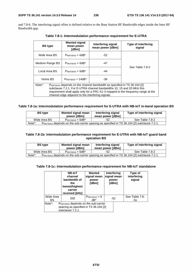
ETSI
ETSI TS 136 141 V14.3.0 (2017-04)2383GPP TS 36.141 version 14.3.0 Release 14
and 7.8-6. The interfering signal offset is defined relative to the Base Station RF Bandwidth edges inside the Inter RF Bandwidth gap.
Table 7.8-1: Intermodulation performance requirement for E-UTRA
BS type Wanted signal mean power
[dBm]
Interfering signal mean power [dBm]
Type of interfering signal
Wide Area BS PREFSENS + 6dB* -52
See Table 7.8-2 Medium Range BS PREFSENS + 6dB* -47
Local Area BS PREFSENS + 6dB* -44
Home BS PREFSENS + 14dB* -36
Note*: PREFSENS depends on the channel bandwidth as specified in TS 36.104 [2] subclause 7.2.1. For E-UTRA channel bandwidths 10, 15 and 20 MHz this requirement shall apply only for a FRC A1-3 mapped to the frequency range at the channel edge adjacent to the interfering signals.
Table 7.8-1a: Intermodulation performance requirement for E-UTRA with NB-IoT in-band operation BS
BS type Wanted signal mean power [dBm]
Interfering signal mean power [dBm]
Type of interfering signal
Wide Area BS PREFSENS + 6dB* -52 See Table 7.8-2 Note*: PREFSENS depends on the sub-carrier spacing as specified in TS 36.104 [2] subclause 7.2.1.
Table 7.8-1b: Intermodulation performance requirement for E-UTRA with NB-IoT guard band operation BS
BS type Wanted signal mean power [dBm]
Interfering signal mean power [dBm]
Type of interfering signal
Wide Area BS PREFSENS + 6dB* -52 See Table 7.8-2 Note*: PREFSENS depends on the sub-carrier spacing as specified in TS 36.104 [2] subclause 7.2.1.
Table 7.8-1c: Intermodulation performance requirement for NB-IoT standalone
NB-IoT channel
bandwidth of the
lowest/highest carrier
received [kHz]
Wanted signal mean
power [dBm]
Interfering signal mean
power [dBm]
Type of interfering
signal
Wide Area BS 200 PREFSENS + 6
dB* -52 See Table 7.8-2a
Note*: PREFSENS depends on the sub-carrier spacing as specified in TS 36.104 [2] subclause 7.2.1.

ETSI
ETSI TS 136 141 V14.3.0 (2017-04)2393GPP TS 36.141 version 14.3.0 Release 14
Table 7.8-2: Interfering signal for Intermodulation performance requirement for E-UTRA or E-UTRA with NB-IoT in-band/guard band operation BS
E-UTRA channel
bandwidth of the
lowest/highest carrier
received [MHz]
Interfering signal centre frequency offset from the
lower/upper Base Station RF
Bandwidth edge [MHz]
Type of interfering signal
1.4 ±2.1 CW ±4.9 1.4MHz E-UTRA signal
3 ±4.5 CW
±10.5 3MHz E-UTRA signal
5 ±7.5 CW
±17.5 5MHz E-UTRA signal
10 ±7. 375 CW ±17.5 5MHz E-UTRA signal
15 ±7.25 CW ±17.5 5MHz E-UTRA signal
20 ±7.125 CW ±17.5 5MHz E-UTRA signal
Table 7.8-2a: Interfering signal for Intermodulation performance requirement for NB-IoT standalone operation BS
Channel bandwidth of
the lowest/highest
carrier received
[MHz]
Interfering signal centre frequency offset from the
lower/upper Base Station RF
Bandwidth edge [MHz]
Type of interfering signal
0.2 ±7.575 CW ±17.5 5 MHz E-UTRA signal

ETSI
ETSI TS 136 141 V14.3.0 (2017-04)2403GPP TS 36.141 version 14.3.0 Release 14
Table 7.8-3: Narrowband intermodulation performance requirement for Wide Area BS for E-UTRA
E-UTRA channel
bandwidth of the
lowest/highest carrier
received [MHz]
Wanted signal mean power [dBm]
Interfering signal mean power
[dBm]
Interfering RB centre frequency offset from the
lower/upper Base Station RF
Bandwidth edge or sub-block edge inside a sub-block
gap [kHz]
Type of interfering signal
1.4 PREFSENS + 6dB* -52 ±270 CW
-52 ±790 1.4 MHz E-UTRA signal, 1 RB**
3 PREFSENS + 6dB* -52 ±270 CW
-52 ±780 3.0 MHz E-UTRA signal, 1 RB**
5 PREFSENS + 6dB* -52 ±360 CW
-52 ±1060 5 MHz E-UTRA signal, 1 RB**
10 PREFSENS + 6dB* (***)
-52 ±325 CW
-52 ±1240 5 MHz E-UTRA signal, 1 RB**
15 PREFSENS + 6dB* (***)
-52 ±380 CW
-52 ±1600 5MHz E-UTRA signal, 1
RB**
20 PREFSENS + 6dB* (***)
-52 ±345 CW
-52 ±1780 5MHz E-UTRA signal, 1
RB** Note*: PREFSENS is related to the channel bandwidth as specified in TS 36.104 [2] subclause 7.2.1. Note**: Interfering signal consisting of one resource block positioned at the stated offset, the channel bandwidth of
the interfering signal is located adjacently to the lower/upper Base Station RF Bandwidth edge. Note***: This requirement shall apply only for a FRC A1-3 mapped to the frequency range at the channel edge
adjacent to the interfering signals

ETSI
ETSI TS 136 141 V14.3.0 (2017-04)2413GPP TS 36.141 version 14.3.0 Release 14
Table 7.8-3a: Narrowband intermodulation performance requirement for Wide Area BS for E-UTRA with NB-IoT in-band operation BS
E-UTRA channel
bandwidth of the
lowest/highest carrier
received [MHz]
Wanted signal mean power [dBm]
Interfering signal mean power
[dBm]
Interfering RB centre frequency offset from the
lower/upper Base Station RF
Bandwidth edge or sub-block edge inside a sub-block
gap [kHz]
Type of interfering signal
1.4 PREFSENS + 6dB* -52 ±270 CW
-52 ±790 1.4 MHz E-UTRA signal, 1 RB**
3 PREFSENS + 6dB* -52 ±270 CW
-52 ±780 3.0 MHz E-UTRA signal, 1 RB**
5 PREFSENS + 6dB* -52 ±360**** CW
-52 ±1060 5 MHz E-UTRA signal, 1 RB**
10 PREFSENS + 6dB* (***)
-52 ±325**** CW
-52 ±1240 5 MHz E-UTRA signal, 1 RB**
15 PREFSENS + 6dB* (***)
-52 ±380**** CW
-52 ±1600 5MHz E-UTRA signal, 1 RB**
20 PREFSENS + 6dB* (***)
-52 ±345**** CW
-52 ±1780 5MHz E-UTRA signal, 1 RB**
Note*: PREFSENS depends on the sub-carrier spacing as specified in TS 36.104 [2] subclause 7.2.1. Note**: Interfering signal consisting of one resource block positioned at the stated offset, the channel bandwidth of
the interfering signal is located adjacently to the lower/upper Base Station RF Bandwidth edge. Note***: This requirement shall apply only for a FRC A1-3 mapped to the frequency range at the channel edge
adjacent to the interfering signals. Note****: The frequency offset shall be adjusted to accommodate the IMD product to fall in the NB-IoT RB for NB-IoT
in-band operation.

ETSI
ETSI TS 136 141 V14.3.0 (2017-04)2423GPP TS 36.141 version 14.3.0 Release 14
Table 7.8-3b: Narrowband intermodulation performance requirement for Wide Area BS for E-UTRA with NB-IoT guard band operation BS
E-UTRA channel
bandwidth of the
lowest/highest carrier
received [MHz]
Wanted signal mean power [dBm]
Interfering signal mean power
[dBm]
Interfering RB centre frequency offset from the
lower/upper Base Station RF
Bandwidth edge or sub-block edge inside a sub-block
gap [kHz]
Type of interfering signal
1.4 PREFSENS + 6dB* -52 ±270 CW
-52 ±790 1.4 MHz E-UTRA signal, 1 RB**
3 PREFSENS + 6dB* -52 ±270 CW
-52 ±780 3.0 MHz E-UTRA signal, 1 RB**
5 PREFSENS + 6dB* -52 ±360**** CW
-52 ±1060 5 MHz E-UTRA signal, 1 RB**
10 PREFSENS + 6dB* (***)
-52 ±325**** CW
-52 ±1240 5 MHz E-UTRA signal, 1 RB**
15 PREFSENS + 6dB* (***)
-52 ±380**** CW
-52 ±1600 5MHz E-UTRA signal, 1 RB**
20 PREFSENS + 6dB* (***)
-52 ±345**** CW
-52 ±1780 5MHz E-UTRA signal, 1 RB**
Note*: PREFSENS depends on the sub-carrier spacing as specified in TS 36.104 [2] subclause 7.2.1. Note**: Interfering signal consisting of one resource block positioned at the stated offset, the channel bandwidth of
the interfering signal is located adjacently to the lower/upper Base Station RF Bandwidth edge. Note***: This requirement shall apply only for a FRC A1-3 mapped to the frequency range at the channel edge
adjacent to the interfering signals. Note****: The frequency offset shall be adjusted to accommodate the IMD product to fall in the NB-IoT RB for NB-IoT
guard band operation.
Table 7.8-3c: Narrowband intermodulation performance requirement for Wide Area BS for NB-IoT standalone
Channel bandwidth of
the lowest/highest
carrier received
[MHz]
Wanted signal mean power [dBm]
Interfering signal mean power
[dBm]
Interfering RB centre frequency offset from the
lower/upper Base Station RF
Bandwidth edge or sub-block edge inside a sub-block
gap [kHz]
Type of interfering signal
0.2 PREFSENS + [6dB]* -52 ±340 CW
-52 ±880 5MHz E-UTRA signal, 1 RB**
Note*: PREFSENS depends on the sub-carrier spacing as specified in TS 36.104 [2] subclause 7.2.1. Note**: Interfering signal consisting of one resource block positioned at the stated offset, the channel bandwidth of
the interfering signal is located adjacently to the lower/upper Base Station RF Bandwidth edge.

ETSI
ETSI TS 136 141 V14.3.0 (2017-04)2433GPP TS 36.141 version 14.3.0 Release 14
Table 7.8-4: Narrowband intermodulation performance requirement for Local Area BS for E-UTRA
E-UTRA channel
bandwidth of the
lowest/highest carrier
received [MHz]
Wanted signal mean power [dBm]
Interfering signal mean power
[dBm]
Interfering RB centre frequency offset from the
lower/upper Base Station RF
Bandwidth edge or sub-block edge inside a sub-block
[kHz]
Type of interfering signal
1.4 PREFSENS + 6dB* -44 ±270 CW
-44 ±790 1.4 MHz E-UTRA signal, 1 RB**
3 PREFSENS + 6dB* -44 ±275 CW
-44 ±790 3.0 MHz E-UTRA signal, 1 RB**
5 PREFSENS + 6dB* -44 ±360 CW
-44 ±1060 5 MHz E-UTRA signal, 1 RB**
10 PREFSENS + 6dB* (***)
-44 ±415 CW
-44 ±1420 5 MHz E-UTRA signal, 1 RB**
15 PREFSENS + 6dB* (***)
-44 ±380 CW
-44 ±1600 5MHz E-UTRA signal, 1
RB**
20 PREFSENS + 6dB* (***)
-44 ±345 CW
-44 ±1780 5MHz E-UTRA signal, 1
RB** Note*: PREFSENS is related to the channel bandwidth as specified in TS 36.104 [2] subclause 7.2.1. Note**: Interfering signal consisting of one resource block positioned at the stated offset, the channel bandwidth of
the interfering signal is located adjacently to the lower/upper Base Station RF Bandwidth edge. Note***: This requirement shall apply only for a FRC A1-3 mapped to the frequency range at the channel edge
adjacent to the interfering signals

ETSI
ETSI TS 136 141 V14.3.0 (2017-04)2443GPP TS 36.141 version 14.3.0 Release 14
Table 7.8-5: Narrowband intermodulation performance requirement for Home BS for E-UTRA
E-UTRA channel
bandwidth [MHz]
Wanted signal mean power [dBm]
Interfering signal mean power [dBm]
Interfering RB centre frequency offset from the channel edge of
the wanted signal [kHz]
Type of interfering signal
1.4 PREFSENS + 14dB* -36 270 CW
-36 790 1.4 MHz E-UTRA signal, 1
RB**
3 PREFSENS + 14dB* -36 270 CW
-36 780 3.0 MHz E-UTRA signal, 1 RB**
5 PREFSENS + 14dB* -36 360 CW
-36 1060 5 MHz E-UTRA signal, 1 RB**
10 PREFSENS + 14dB*
(***)
-36 325 CW
-36 1240 5 MHz E-UTRA signal, 1 RB**
15 PREFSENS + 14dB*
(***)
-36 380 CW
-36 1600 5MHz E-UTRA signal, 1 RB**
20 PREFSENS + 14dB* (***)
-36 345 CW
-36 1780 5MHz E-UTRA signal, 1 RB**
Note*: PREFSENS is related to the channel bandwidth as specified in TS 36.104 [2] subclause 7.2.1. Note**: Interfering signal consisting of one resource block positioned at the stated offset, the channel bandwidth of
the interfering signal is located adjacently to the channel edge of the wanted signal. Note***: This requirement shall apply only for a FRC A1-3 mapped to the frequency range at the channel edge
adjacent to the interfering signals
Table 7.8-6: Narrowband intermodulation performance requirement for Medium Range BS for E-UTRA
E-UTRA channel
bandwidth of the
lowest/highest carrier
received [MHz]
Wanted signal mean power [dBm]
Interfering signal mean power
[dBm]
Interfering RB centre frequency
offset to the lower (higher) edge or sub-block edge
inside a sub-block gap [kHz]
Type of interfering signal
1.4 PREFSENS + 6dB* −47 ±270 CW
−47 ±790 1.4 MHz E-UTRA signal, 1 RB**
3 PREFSENS + 6dB* −47 ±270 CW
−47 ±780 3.0 MHz E-UTRA signal, 1 RB**
5 PREFSENS + 6dB* −47 ±360 CW
−47 ±1060 5 MHz E-UTRA signal, 1 RB**
10 PREFSENS + 6dB* (***)
−47 ±325 CW
−47 ±1240 5 MHz E-UTRA signal, 1 RB**
15 PREFSENS + 6dB* (***)
−47 ±380 CW
−47 ±1600 5MHz E-UTRA signal, 1 RB**
20 PREFSENS + 6dB* (***)
−47 ±345 CW
−47 ±1780 5MHz E-UTRA signal, 1
RB** Note*: PREFSENS is related to the channel bandwidth as specified in TS 36.104 [2] subclause 7.2.1. Note**: Interfering signal consisting of one resource block positioned at the stated offset, the channel bandwidth of
the interfering signal is located adjacently to the lower (higher) edge. Note***: This requirement shall apply only for a FRC A1-3 mapped to the frequency range at the channel edge
adjacent to the interfering signals

ETSI
ETSI TS 136 141 V14.3.0 (2017-04)2453GPP TS 36.141 version 14.3.0 Release 14
NOTE: If the above Test Requirement differs from the Minimum Requirement then the Test Tolerance applied for this test is non-zero. The relationship between Minimum Requirements and Test Requirements is defined in subclause 4.1 and the explanation of how the Minimum Requirement has been relaxed by the Test Tolerance is given in Annex G.
8 Performance requirement
8.1 General Performance requirements are specified for a number of test environments and multipath channel classes.
Unless stated otherwise, performance requirements apply for a single carrier only. Performance requirements for a BS supporting carrier aggregation are defined in terms of single carrier requirements. The requirements only apply to those measurement channels that are supported by the base station.
The performance requirements for High Speed Train conditions defined in Annex B.3 are optional.
The performance requirements for UL timing adjustment scenario 2 defined in Annex B.4 are optional.
For BS with receiver antenna diversity the required SNR shall be applied separately at each antenna port.
In tests performed with signal generators a synchronization signal may be provided, from the base station to the signal generator, to enable correct timing of the wanted signal.
For tests in clause 8 the transmitter may be off.
8.2 Performance requirements for PUSCH
8.2.1 Performance requirements of PUSCH in multipath fading propagation conditions transmission on single antenna port
8.2.1.1 Definition and applicability
The performance requirement of PUSCH is determined by a minimum required throughput for a given SNR. The required throughput is expressed as a fraction of maximum throughput for the FRCs listed in Annex A. The performance requirements assume HARQ re-transmissions.
A test for a specific channel bandwidth is only applicable if the BS supports it.
For a BS supporting FDD multiple channel bandwidths but not supporting FDD UL carrier aggregation, only the tests for the lowest and the highest FDD channel bandwidths supported by the BS are applicable. For a BS supporting TDD multiple channel bandwidths but not supporting TDD UL carrier aggregation, only the tests for the lowest and the highest TDD channel bandwidths supported by the BS are applicable.For a BS supporting FDD UL carrier aggregation, only the FDD CC combination with largest aggregated bandwidth is used for the test. If there is more than one combination the FDD CC combination with the largest number of component carriers is used for the test. For this CC combination the tests using full PRB allocation FRC are conducted on per CC basis and measured by the required SNR levels corresponding to the bandwidths used on the different CCs.
For a BS supporting TDD UL carrier aggregation, only the TDD CC combination with largest aggregated bandwidth is used for the test. If there is more than one combination the TDD CC combination with the largest number of component carriers is used for the test. For this CC combination the tests using full PRB allocation FRC are conducted on per CC basis and measured by the required SNR levels corresponding to the bandwidths used on the different CCs.
For a BS supporting carrier aggregation the tests with single PRB FRC are conducted on any single component carrier only.

ETSI
ETSI TS 136 141 V14.3.0 (2017-04)2463GPP TS 36.141 version 14.3.0 Release 14
8.2.1.2 Minimum Requirement
The minimum requirement is in TS 36.104 [2] subclause 8.2.1.1.
8.2.1.3 Test Purpose
The test shall verify the receiver’s ability to achieve throughput under multipath fading propagation conditions for a given SNR.
8.2.1.4 Method of test
8.2.1.4.1 Initial Conditions
Test environment: Normal, see subclause D.2.
RF channels to be tested: M; see subclause 4.7.
1) Connect the BS tester generating the wanted signal, multipath fading simulators and AWGN generators to all BS antenna connectors for diversity reception via a combining network as shown in Annex I.3.2.
8.2.1.4.2 Procedure
1) Adjust the AWGN generator, according to the channel bandwidth, defined in Table 8.2.1.4.2-1.
Table 8.2.1.4.2-1: AWGN power level at the BS input
Channel bandwidth [MHz] AWGN power level 1.4 -92.7dBm / 1.08MHz 3 -88.7dBm / 2.7MHz 5 -86.5dBm / 4.5MHz
10 -83.5dBm / 9MHz 15 -81.7dBm / 13.5MHz 20 -80.4dBm / 18MHz
2) The characteristics of the wanted signal shall be configured according to the corresponding UL reference measurement channel defined in annex A and the test parameters in Table 8.2.1.4.2-2. For reference channels using 1 resource block the resource block in the middle of the channel bandwidth shall be used. In case the number of resource blocks in the channel bandwidth are even the one in the middle with lower number is to be used for testing.
Table 8.2.1.4.2-2: Test parameters for testing PUSCH
Parameter Value Maximum number of HARQ transmissions 4
RV sequence 0, 2, 3, 1, 0, 2, 3, 1 Uplink-downlink allocation for TDD Configuration 1 (2:2)
3) The multipath fading emulators shall be configured according to the corresponding channel model defined in annex B.
4) Adjust the equipment so that required SNR specified in Table 8.2.1.5-1 to 8.2.1.5-6 is achieved at the BS input.
5) For each of the reference channels in Table 8.2.1.5-1 to 8.2.1.5-6 applicable for the base station, measure the throughput, according to annex E.
8.2.1.5 Test Requirement
The throughput measured according to subclause 8.2.1.4.2 shall not be below the limits for the SNR levels specified in Table 8.2.1.5-1 to 8.2.1.5-6.

ETSI
ETSI TS 136 141 V14.3.0 (2017-04)2473GPP TS 36.141 version 14.3.0 Release 14
Table 8.2.1.5-1: Test requirements for PUSCH, 1.4 MHz Channel Bandwidth
Number of TX antennas
Number of RX antennas
Cyclic prefix Propagation conditions
and correlation
matrix (Annex B)
FRC (Annex A)
Fraction of maximum
throughput
SNR [dB]
1 2 Normal EPA 5Hz Low A3-2 30% -3.5 70% 0.7
A4-3 70% 11.2 A5-2 70% 18.3
EVA 5Hz Low A3-1 30% -2.1 70% 2.4
A4-1 30% 5.0 70% 11.9
A5-1 70% 19.2 EVA 70Hz Low
A3-2 30% -3.3 70% 1.3
A4-3 30% 4.6 70% 12.5
ETU 70Hz* Low
A3-1 30% -1.8 70% 3.0
ETU 300Hz* Low
A3-1 30% -1.6 70% 3.5

ETSI
ETSI TS 136 141 V14.3.0 (2017-04)2483GPP TS 36.141 version 14.3.0 Release 14
Extended ETU 70Hz* Low
A4-2 30% 5.4 70% 14.1
4 Normal EPA 5Hz Low A3-2 30% -6.0 70% -2.5
A4-3 70% 7.7 A5-2 70% 15.0
EVA 5Hz Low A3-1 30% -4.4 70% -0.7
A4-1 30% 1.9 70% 8.4
A5-1 70% 16.0 EVA 70Hz Low
A3-2 30% -5.7 70% -2.1
A4-3 30% 1.4 70% 8.9
ETU 70Hz* Low
A3-1 30% -4.2 70% -0.4
ETU 300Hz* Low
A3-1 30% -4.0 70% 0.0
ETU 600Hz** Low
A13-1 30% -0.3 70% 6.7
Extended ETU 70Hz* Low
A4-2 30% 2.2 70% 10.5
8 Normal EPA 5Hz Low A3-2 30% -8.8 70% -5.8
A4-3 70% 4.6 A5-2 70% 11.5
EVA 5Hz Low A3-1 30% -6.6 70% -3.2
A4-1 30% -1.1 70% 5.2
A5-1 70% 12.3 EVA 70Hz Low
A3-2 30% -8.4 70% -5.2
A4-3 30% -1.9 70% 5.4
ETU 70Hz* Low
A3-1 30% -6.2 70% -3.0
ETU 300Hz* Low
A3-1 30% -6.1 70% -2.7
Extended ETU 70Hz* Low
A4-2 30% -0.5 70% 7.0
Note*: Not applicable for Local Area BS and Home BS. Note**: Not applicable for Local Area BS and Home BS, and only applicable for BS supporting ETU600.
Table 8.2.1.5-2: Test requirements for PUSCH, 3 MHz Channel Bandwidth
Number of TX antennas
Number of RX antennas
Cyclic prefix Propagation conditions
and correlation
matrix (Annex B)
FRC (Annex A)
Fraction of maximum
throughput
SNR [dB]
1 2 Normal EPA 5Hz Low A3-3 30% -3.5 70% 0.7
A4-4 70% 11.5 A5-3 70% 18.7
EVA 5Hz Low A3-1 30% -2.2 70% 2.4
A4-1 30% 4.9 70% 12.1
A5-1 70% 19.4 EVA 70Hz Low
A3-3 30% -3.4 70% 1.2

ETSI
ETSI TS 136 141 V14.3.0 (2017-04)2493GPP TS 36.141 version 14.3.0 Release 14
A4-4 30% 5.3 70% 13.1
ETU 70Hz* Low
A3-1 30% -1.9 70% 3.0
ETU 300Hz* Low
A3-1 30% -1.6 70% 3.5
Extended ETU 70Hz* Low
A4-2 30% 5.3 70% 14.1
4 Normal EPA 5Hz Low A3-3 30% -6.2 70% -2.8
A4-4 70% 8.3 A5-3 70% 15.0
EVA 5Hz Low A3-1 30% -4.4 70% -0.7
A4-1 30% 1.8 70% 8.4
A5-1 70% 16.0 EVA 70Hz Low
A3-3 30% -5.9 70% -2.3
A4-4 30% 2.2 70% 9.3
ETU 70Hz* Low
A3-1 30% -4.2 70% -0.3
ETU 300Hz* Low
A3-1 30% -4.0 70% 0.0
ETU 600Hz** Low
A13-2 30% -0.5 70% 6.4
Extended ETU 70Hz* Low
A4-2 30% 2.1 70% 10.5
8 Normal EPA 5Hz Low A3-3 30% -9.0 70% -6.0
A4-4 70% 4.7 A5-3 70% 11.7
EVA 5Hz Low A3-1 30% -6.5 70% -3.4
A4-1 30% -1.0 70% 5.0
A5-1 70% 12.3 EVA 70Hz Low
A3-3 30% -8.7 70% -5.3
A4-4 30% -2.2 70% 5.4
ETU 70Hz* Low
A3-1 30% -6.4 70% -3.1
ETU 300Hz* Low
A3-1 30% -6.2 70% -2.7
Extended ETU 70Hz* Low
A4-2 30% -0.6 70% 7.1
Note*: Not applicable for Local Area BS and Home BS. Note**: Not applicable for Local Area BS and Home BS, and only applicable for BS supporting ETU600.
Table 8.2.1.5-3: Test requirements for PUSCH, 5 MHz Channel Bandwidth
Number of TX antennas
Number of RX antennas
Cyclic prefix Propagation conditions
and correlation
matrix (Annex B)
FRC (Annex A)
Fraction of maximum
throughput
SNR [dB]
1 2 Normal EPA 5Hz Low A3-4 30% -4.1 70% -0.1
A4-5 70% 11.0 A5-4 70% 18.6
EVA 5Hz Low A3-1 30% -2.1

ETSI
ETSI TS 136 141 V14.3.0 (2017-04)2503GPP TS 36.141 version 14.3.0 Release 14
70% 2.4 A4-1 30% 4.9
70% 12.1 A5-1 70% 19.2
EVA 70Hz Low
A3-4 30% -3.9 70% 0.5
A4-5 30% 4.9 70% 12.9
ETU 70Hz* Low
A3-1 30% -1.9 70% 3.0
ETU 300Hz* Low
A3-1 30% -1.6 70% 3.5
Extended ETU 70Hz* Low
A4-2 30% 5.4 70% 14.1
4 Normal EPA 5Hz Low A3-4 30% -6.5 70% -3.2
A4-5 70% 8.2 A5-4 70% 15.0
EVA 5Hz Low A3-1 30% -4.5 70% -0.8
A4-1 30% 1.8 70% 8.5
A5-1 70% 16.1 EVA 70Hz Low
A3-4 30% -6.3 70% -2.7
A4-5 30% 1.8 70% 8.9
ETU 70Hz* Low
A3-1 30% -4.2 70% -0.3
ETU 300Hz* Low
A3-1 30% -4.0 70% 0.0
ETU 600Hz** Low
A13-3 30% -0.3 70% 6.7
Extended ETU 70Hz* Low
A4-2 30% 2.2 70% 10.5
8 Normal EPA 5Hz Low A3-4 30% -9.5 70% -6.6
A4-5 70% 4.6 A5-4 70% 11.9
EVA 5Hz Low A3-1 30% -6.5 70% -3.3
A4-1 30% -1.3 70% 5.0
A5-1 70% 12.3 EVA 70Hz Low
A3-4 30% -9.3 70% -6.1
A4-5 30% -1.9 70% 5.2
ETU 70Hz* Low
A3-1 30% -6.3 70% -2.8
ETU 300Hz* Low
A3-1 30% -6.3 70% -2.7
Extended ETU 70Hz* Low
A4-2 30% -0.6 70% 7.0
Note*: Not applicable for Local Area BS and Home BS. Note**: Not applicable for Local Area BS and Home BS, and only applicable for BS supporting ETU600.
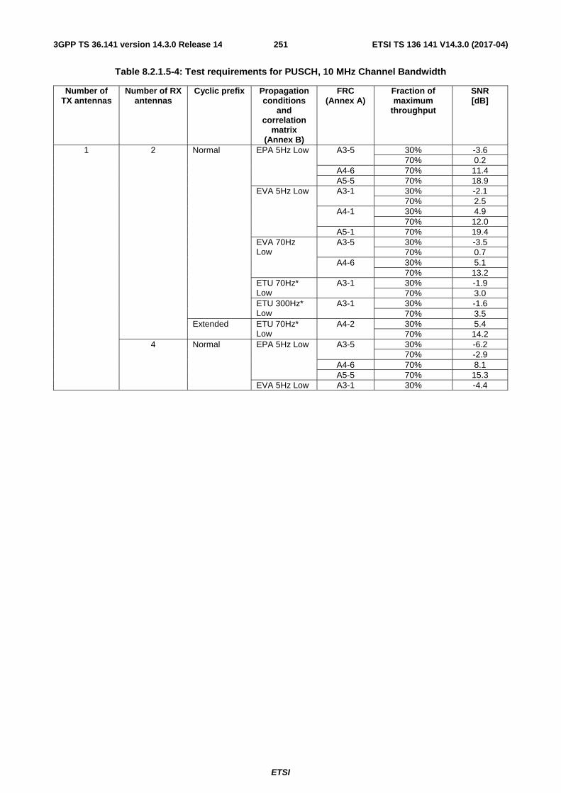
ETSI
ETSI TS 136 141 V14.3.0 (2017-04)2513GPP TS 36.141 version 14.3.0 Release 14
Table 8.2.1.5-4: Test requirements for PUSCH, 10 MHz Channel Bandwidth
Number of TX antennas
Number of RX antennas
Cyclic prefix Propagation conditions
and correlation
matrix (Annex B)
FRC (Annex A)
Fraction of maximum
throughput
SNR [dB]
1 2 Normal EPA 5Hz Low A3-5 30% -3.6 70% 0.2
A4-6 70% 11.4 A5-5 70% 18.9
EVA 5Hz Low A3-1 30% -2.1 70% 2.5
A4-1 30% 4.9 70% 12.0
A5-1 70% 19.4 EVA 70Hz Low
A3-5 30% -3.5 70% 0.7
A4-6 30% 5.1 70% 13.2
ETU 70Hz* Low
A3-1 30% -1.9 70% 3.0
ETU 300Hz* Low
A3-1 30% -1.6 70% 3.5
Extended ETU 70Hz* Low
A4-2 30% 5.4 70% 14.2
4 Normal EPA 5Hz Low A3-5 30% -6.2 70% -2.9
A4-6 70% 8.1 A5-5 70% 15.3
EVA 5Hz Low A3-1 30% -4.4

ETSI
ETSI TS 136 141 V14.3.0 (2017-04)2523GPP TS 36.141 version 14.3.0 Release 14
70% -0.6 A4-1 30% 1.8
70% 8.5 A5-1 70% 16.1
EVA 70Hz Low
A3-5 30% -6.1 70% -2.3
A4-6 30% 1.3 70% 8.6
ETU 70Hz* Low
A3-1 30% -4.2 70% -0.3
ETU 300Hz* Low
A3-1 30% -4.0 70% 0.0
ETU 600Hz** Low
A13-4 30% -0.4 70% 6.8
Extended ETU 70Hz* Low
A4-2 30% 2.3 70% 10.9
8 Normal EPA 5Hz Low A3-5 30% -9.2 70% -6.1
A4-6 70% 4.8 A5-5 70% 12.1
EVA 5Hz Low A3-1 30% -6.3 70% -3.2
A4-1 30% -1.1 70% 5.1
A5-1 70% 12.5 EVA 70Hz Low
A3-5 30% -9.1 70% -5.6
A4-6 30% -2.0 70% 5.3
ETU 70Hz* Low
A3-1 30% -6.2 70% -3.0
ETU 300Hz* Low
A3-1 30% -6.2 70% -2.7
Extended ETU 70Hz* Low
A4-2 30% -0.5 70% 7.1
Note*: Not applicable for Local Area BS and Home BS. Note**: Not applicable for Local Area BS and Home BS, and only applicable for BS supporting ETU600.
Table 8.2.1.5-5: Test requirements for PUSCH, 15 MHz Channel Bandwidth
Number of TX antennas
Number of RX antennas
Cyclic prefix Propagation conditions
and correlation
matrix (Annex B)
FRC (Annex A)
Fraction of maximum
throughput
SNR [dB]
1 2 Normal EPA 5Hz Low A3-6 30% -3.9 70% -0.2
A4-7 70% 11.9 A5-6 70% 19.4
EVA 5Hz Low A3-1 30% -2.2 70% 2.4
A4-1 30% 4.8 70% 12.0
A5-1 70% 19.3 EVA 70Hz Low
A3-6 30% -3.9 70% 0.3
A4-7 30% 4.8 70% 13.5
ETU 70Hz* Low
A3-1 30% -1.9 70% 3.0
ETU 300Hz* Low
A3-1 30% -1.6 70% 3.5
Extended A4-2 30% 5.5

ETSI
ETSI TS 136 141 V14.3.0 (2017-04)2533GPP TS 36.141 version 14.3.0 Release 14
ETU 70Hz* Low
70% 14.2
4 Normal EPA 5Hz Low A3-6 30% -6.6 70% -3.2
A4-7 70% 8.2 A5-6 70% 15.6
EVA 5Hz Low A3-1 30% -4.4 70% -0.6
A4-1 30% 1.8 70% 8.5
A5-1 70% 16.3 EVA 70Hz Low
A3-6 30% -6.4 70% -2.7
A4-7 30% 1.3 70% 9.1
ETU 70Hz* Low
A3-1 30% -4.2 70% -0.4
ETU 300Hz* Low
A3-1 30% -4.0 70% 0.0
ETU 600Hz** Low
A13-5 30% -0.3 70% 7.0
Extended ETU 70Hz* A4-2 30% 2.2 70% 10.7
8 Normal EPA 5Hz Low A3-6 30% -9.8 70% -6.7
A4-7 70% 5.0 A5-6 70% 12.4
EVA 5Hz Low A3-1 30% -6.5 70% -3.4
A4-1 30% -1.1 70% 5.0
A5-1 70% 12.3 EVA 70Hz Low
A3-6 30% -9.5 70% -6.2
A4-7 30% -1.9 70% 5.6
ETU 70Hz* Low
A3-1 30% -6.4 70% -3.0
ETU 300Hz* Low
A3-1 30% -6.3 70% -2.7
Extended ETU 70Hz* Low
A4-2 30% -0.5 70% 7.3
Note*: Not applicable for Local Area BS and Home BS. Note**: Not applicable for Local Area BS and Home BS, and only applicable for BS supporting ETU600.
Table 8.2.1.5-6: Test requirements for PUSCH, 20 MHz Channel Bandwidth
Number of TX antennas
Number of RX antennas
Cyclic prefix Propagation conditions
and correlation
matrix (Annex B)
FRC (Annex A)
Fraction of maximum
throughput
SNR [dB]
1 2 Normal EPA 5Hz Low A3-7 30% -3.6 70% 0.2
A4-8 70% 12.1 A5-7 70% 20.3
EVA 5Hz Low A3-1 30% -2.1 70% 2.4
A4-1 30% 4.9 70% 12.1
A5-1 70% 19.3 EVA 70Hz Low
A3-7 30% -3.5 70% 0.8
A4-8 30% 4.8

ETSI
ETSI TS 136 141 V14.3.0 (2017-04)2543GPP TS 36.141 version 14.3.0 Release 14
70% 13.6 ETU 70Hz* Low
A3-1 30% -1.8 70% 3.0
ETU 300Hz* Low
A3-1 30% -1.5 70% 3.5
Extended ETU 70Hz* Low
A4-2 30% 5.3 70% 14.2
4 Normal EPA 5Hz Low A3-7 30% -6.2 70% -2.9
A4-8 70% 8.1 A5-7 70% 16.5
EVA 5Hz Low A3-1 30% -4.5 70% -0.7
A4-1 30% 1.8 70% 8.5
A5-1 70% 16.2 EVA 70Hz Low
A3-7 30% -6.1 70% -2.3
A4-8 30% 1.3 70% 9.2
ETU 70Hz* Low
A3-1 30% -3.8 70% -0.3
ETU 300Hz* Low
A3-1 30% -4.0 70% -0.1
ETU 600Hz** Low
A13-6 30% -0.3 70% 7.0
Extended ETU 70Hz* Low
A4-2 30% 2.2 70% 10.6
8 Normal EPA 5Hz Low A3-7 30% -9.1 70% -6.1
A4-8 70% 4.9 A5-7 70% 13.1
EVA 5Hz Low A3-1 30% -6.4 70% -3.3
A4-1 30% -1.1 70% 5.2
A5-1 70% 12.6 EVA 70Hz Low
A3-7 30% -9.1 70% -5.5
A4-8 30% -1.6 70% 5.5
ETU 70Hz* Low
A3-1 30% -6.3 70% -2.9
ETU 300Hz* Low
A3-1 30% -6.2 70% -2.7
Extended ETU 70Hz* Low
A4-2 30% -0.6 70% 7.1
Note Not applicable for Local Area BS and Home BS. Note**: Not applicable for Local Area BS and Home BS, and only applicable for BS supporting ETU600.
NOTE: If the above Test Requirement differs from the Minimum Requirement then the Test Tolerance applied for this test is non-zero. The Test Tolerance for this test and the explanation of how the Minimum Requirement has been relaxed by the Test Tolerance is given in Annex G.
8.2.1A Performance requirements of PUSCH in multipath fading propagation conditions transmission on two antenna ports
8.2.1A.1 Definition and applicability
The performance requirement of PUSCH is determined by a minimum required throughput for a given SNR. The required throughput is expressed as a fraction of maximum throughput for the FRCs listed in Annex A. The performance requirements assume HARQ re-transmissions.

ETSI
ETSI TS 136 141 V14.3.0 (2017-04)2553GPP TS 36.141 version 14.3.0 Release 14
A test for a specific channel bandwidth is only applicable if the BS supports it.
For a BS supporting multiple channel bandwidths only the tests for the lowest and the highest channel bandwidths supported by the BS are applicable.
For the tests on two antenna ports the HARQ retransmissions for multiple codewords are independent.
8.2.1A.2 Minimum Requirement
The minimum requirement is in TS 36.104 [2] subclause 8.2.1.1.
8.2.1A.3 Test Purpose
The test shall verify the receiver’s ability to achieve throughput of two layer spatial multiplexing transmission under multipath fading propagation conditions for a given SNR.
8.2.1A.4 Method of test
8.2.1A.4.1 Initial Conditions
Test environment: Normal, see subclause D.2.
RF channels to be tested: M; see subclause 4.7.
1) Connect the BS tester generating the wanted signal, multipath fading simulators and AWGN generators to all BS antenna connectors for diversity reception via a combining network as shown in Annex I.3.6.
8.2.1A.4.2 Procedure
1) Adjust the AWGN generator, according to the channel bandwidth, defined in Table 8.2.1A.4.2-1.
Table 8.2.1A.4.2-1: AWGN power level at the BS input
Channel bandwidth [MHz] AWGN power level 1.4 -92.7dBm / 1.08MHz 3 -88.7dBm / 2.7MHz 5 -86.5dBm / 4.5MHz
10 -83.5dBm / 9MHz 15 -81.7dBm / 13.5MHz 20 -80.4dBm / 18MHz
2) The characteristics of the wanted signal shall be configured according to the corresponding UL reference measurement channel defined in annex A and the test parameters in Table 8.2.1A.4.2-2. For reference channels using 1 resource block the resource block in the middle of the channel bandwidth shall be used. In case the number of resource blocks in the channel bandwidth are even the one in the middle with lower number is to be used for testing.
Table 8.2.1A.4.2-2 Test parameters for testing PUSCH
Parameter Value Maximum number of HARQ transmissions 4
RV sequence 0, 2, 3, 1, 0, 2, 3, 1 Uplink-downlink allocation for TDD Configuration 1 (2:2)
3) The multipath fading emulators shall be configured according to the corresponding channel model defined in annex B.
4) Adjust the equipment so that required SNR specified in Table 8.2.1A.5-1 to 8.2.1A.5-6 is achieved at the BS input.

ETSI
ETSI TS 136 141 V14.3.0 (2017-04)2563GPP TS 36.141 version 14.3.0 Release 14
5) For each of the reference channels in Table 8.2.1A.5-1 to 8.2.1A.5-6 applicable for the base station, measure the throughput, according to annex E.
8.2.1A.5 Test Requirement
The throughput measured according to subclause 8.2.1A.4.2 shall not be below the limits for the SNR levels specified in Table 8.2.1A.5-1 to 8.2.1A.5-6.
Table 8.2.1A.5-1 Test requirements for PUSCH, 1.4 MHz Channel Bandwidth
Number of TX
antennas
Number of RX
antennas
Cyclic prefix
Propagation conditions and
correlation matrix
(Annex B)
FRC (Annex
A)
Fraction of maximum
throughput
SNR [dB]
2 2 Normal EPA 5Hz Low A3-2 70% [5.4] A4-3 70% 18.5
4 Normal EPA 5Hz Low A3-2 70% 0.7 A4-3 70% 12.7
8 Normal EPA 5Hz Low A3-2 70% -2.2 A4-3 70% 8.3
Table 8.2.1A.5-2 Test requirements for PUSCH, 3 MHz Channel Bandwidth
Number of TX
antennas
Number of RX
antennas
Cyclic prefix
Propagation conditions and
correlation matrix
(Annex B)
FRC (Annex
A)
Fraction of maximum
throughput
SNR [dB]
2 2 Normal EPA 5Hz Low A3-3 70% 5.2 A4-4 70% 18.4
4 Normal EPA 5Hz Low A3-3 70% 1.1 A4-4 70% 12.6
8 Normal EPA 5Hz Low A3-3 70% -2.3 A4-4 70% 8.4
Table 8.2.1A.5-3 Test requirements for PUSCH, 5 MHz Channel Bandwidth
Number of TX
antennas
Number of RX
antennas
Cyclic prefix
Propagation conditions and
correlation matrix
(Annex B)
FRC (Annex
A)
Fraction of maximum
throughput
SNR [dB]
2 2 Normal EPA 5Hz Low A3-4 70% 4.5 A4-5 70% 19.0
4 Normal EPA 5Hz Low A3-4 70% 0.3 A4-5 70% 12.7
8 Normal EPA 5Hz Low A3-4 70% -3.1 A4-5 70% 8.4

ETSI
ETSI TS 136 141 V14.3.0 (2017-04)2573GPP TS 36.141 version 14.3.0 Release 14
Table 8.2.1A.5-4 Test requirements for PUSCH, 10 MHz Channel Bandwidth
Number of TX
antennas
Number of RX
antennas
Cyclic prefix
Propagation conditions and
correlation matrix
(Annex B)
FRC (Annex
A)
Fraction of maximum
throughput
SNR [dB]
2 2 Normal EPA 5Hz Low A3-5 70% 5.0 A4-6 70% 19.4
4 Normal EPA 5Hz Low A3-5 70% 1.0 A4-6 70% 12.8
8 Normal EPA 5Hz Low A3-5 70% -2.5 A4-6 70% 8.7
Table 8.2.1A.5-5 Test requirements for PUSCH, 15 MHz Channel Bandwidth
Number of TX
antennas
Number of RX
antennas
Cyclic prefix
Propagation conditions and
correlation matrix
(Annex B)
FRC (Annex A)
Fraction of maximum
throughput
SNR [dB]
2 2 Normal EPA 5Hz Low A3-6 70% 4.5 A4-7 70% 20.2
4 Normal EPA 5Hz Low A3-6 70% 0.6 A4-7 70% 13.5
8 Normal EPA 5Hz Low A3-6 70% -3.0 A4-7 70% 9.1
Table 8.2.1A.5-6 Test requirements for PUSCH, 20 MHz Channel Bandwidth
Number of TX
antennas
Number of RX
antennas
Cyclic prefix
Propagation conditions and
correlation matrix
(Annex B)
FRC (Annex
A)
Fraction of maximum
throughput
SNR [dB]
2 2 Normal EPA 5Hz Low A3-7 70% 5.2 A4-8 70% 20.5
4 Normal EPA 5Hz Low A3-7 70% 1.3 A4-8 70% 13.5
8 Normal EPA 5Hz Low A3-7 70% -2.6 A4-8 70% 9.1
8.2.2 Performance requirements for UL timing adjustment
8.2.2.1 Definition and applicability
The performance requirement of PUSCH is determined by a minimum required throughput measured for the moving UE at given SNR. The required throughput is expressed as 70% of maximum throughput for the FRCs listed in Annex A. The performance requirements assume HARQ re-transmissions.
In the tests for UL timing adjustment, two signals are configured, one being transmitted by moving UE and the other being transmitted by stationary UE. The transmission of SRS from UE is optional. FRC parameters in Table A.7-1 and Table A.8-1 are applied for both UEs. The received power for both UEs is the same. The resource blocks allocated for both UEs are consecutive. In Scenario 2, Doppler shift is not taken into account.
A test for a specific channel bandwidth is only applicable if the BS supports it.
For a BS supporting multiple channel bandwidths only the tests for the lowest and the highest channel bandwidths supported by the BS are applicable.
This requirement shall not be applied to Local Area BS and Home BS.

ETSI
ETSI TS 136 141 V14.3.0 (2017-04)2583GPP TS 36.141 version 14.3.0 Release 14
8.2.2.2 Minimum Requirement
The minimum requirement is in TS 36.104 [2] subclause 8.2.2.1.
8.2.2.3 Test Purpose
The test shall verify the receiver’s ability to achieve throughput measured for the moving UE at given SNR under moving propagation conditions.
8.2.2.4 Method of test
8.2.2.4.1 Initial Conditions
Test environment: Normal, see subclause D.2.
RF channels to be tested: M; see subclause 4.7.
1) Connect the BS tester generating the wanted signal, multipath fading simulators and AWGN generators to all BS antenna connectors for diversity reception via a combining network as shown in Annex I.3.4.
8.2.2.4.2 Procedure
1) Adjust the AWGN generator, according to the channel bandwidth, defined in Table 8.2.2.4.2-1.
Table 8.2.2.4.2-1: AWGN power level at the BS input
Channel bandwidth [MHz] AWGN power level 1.4 -92.7 dBm / 1.08MHz 3 -88.7 dBm / 2.7MHz 5 -86.5 dBm / 4.5MHz
10 -83.5 dBm / 9MHz 15 -81.7 dBm / 13.5MHz 20 -80.4 dBm / 18MHz
2) The characteristics of the wanted signals (transmitted by moving UE) shall be configured according to the corresponding UL reference measurement channel defined in Annex A and the test parameters in Table 8.2.2.4.2-2.
Table 8.2.2.4.2-2 Test parameters for testing UL timing adjustment
Parameter Value Maximum number of HARQ transmissions 4
RV sequence 0, 2, 3, 1, 0, 2, 3, 1 Uplink-downlink allocation for TDD Configuration 1 (2:2)
Subframes in which PUSCH is transmitted For FDD: subframe #0, #2, #4, #6, and #8 in radio frames For TDD: Subframe #2, #3, #7, #8 in each radio frame
Subframes in which sounding RS is transmitted (Note
1) For FDD: subframe #1 in radio frames For TDD: UpPTS in each radio frame
Note 1: The transmission of SRS is optional.
3) The multipath fading emulators shall be configured according to the corresponding channel model defined in Annex B.

ETSI
ETSI TS 136 141 V14.3.0 (2017-04)2593GPP TS 36.141 version 14.3.0 Release 14
4) Adjust the equipment so that required SNR specified in Table 8.2.2.5-1 is achieved at the BS input.
5) For each of the reference channels in Table 8.2.2.5-1 applicable for the base station, measure the throughput, according to Annex E.
8.2.2.5 Test Requirement
The throughput measured for the moving UE according to subclause 8.2.2.4.2 shall not be below the limits for the SNR levels specified in Table 8.2.2.5-1.
Table 8.2.2.5-1: Test requirements for UL timing adjustment
Number of TX antennas Number of RX
antennas Cyclic prefix Channel
Bandwidth [MHz]
Moving propagation
conditions and correlation
matrix (Annex B)
FRC (Annex A)
SNR [dB]
1 2 Normal
1.4 Scenario 1 Low A7-1 13.7 Scenario 2 Low A8-1 -1.6
3 Scenario 1 Low A7-2 14.0 Scenario 2 Low A8-2 -1.2
5 Scenario 1 Low A7-3 13.8 Scenario 2 Low A8-3 -1.3
10 Scenario 1 Low A7-4 14.4 Scenario 2 Low A8-4 -1.5
15 Scenario 1 Low A7-5 14.6 Scenario 2 Low A8-5 -1.5
20 Scenario 1 Low A7-6 14.5 Scenario 2 Low A8-6 -1.5
NOTE: If the above Test Requirement differs from the Minimum Requirement then the Test Tolerance applied for this test is non-zero. The Test Tolerance for this test is defined in subclause 4.1 and the explanation of how the Minimum Requirement has been relaxed by the Test Tolerance is given in Annex G.
8.2.3 Performance requirements for HARQ-ACK multiplexed on PUSCH
8.2.3.1 Definition and applicability
The performance requirement of HARQ-ACK multiplexed on PUSCH is determined by the two parameters: probability of false detection of the ACK and the probability of detection of ACK. The performance is measured by the required SNR at probability of detection equal to 0.99. The probability of false detection of the ACK shall be 0.01 or less at PUSCH power settings presented in table 8.2.3.5-1.
The probability of detection of ACK on PUSCH is defined as conditional probability of detection of the ACK when the ACK is transmitted on PUSCH allocated RE.
The probability of false detection of the ACK on PUSCH is defined as a conditional probability of erroneous detection of the ACK when data only is sent on PUSCH allocated RE, where HARQ-ACK can be allocated (i.e. by puncturing data). Pseudo-random data shall be used as an input for PUSCH coding and modulation purposes.
These tests shall be performed on one of RE’s, where HARQ-ACK information was multiplexed on PUSCH.
In the test for HARQ-ACK multiplexed on PUSCH data is punctured by HARQ-ACK information in both slots within a subframe on symbols as specified in 36.212 [13] subclause 5.2.2.8. Amount of resources for HARQ-ACK information is calculated according to 36.212 [13] subclause 5.2.2.6. None of CQI, RI nor SRS is to be transmitted in these tests. Tests are performed for one bit HARQ-ACK information (O = 1).
This test is applied for QPSK 1/3 and 16QAM 3/4 modulation and coding schemes, with appropriate fixed reference channels for performance requirement applied as presented in table 8.2.3.5-1. Normal CP, 2 Rx antennas and ETU70 propagation conditions shall be used for this test.
A test for a specific channel bandwidth is only applicable if the BS supports it.

ETSI
ETSI TS 136 141 V14.3.0 (2017-04)2603GPP TS 36.141 version 14.3.0 Release 14
For a BS supporting multiple channel bandwidths only the tests for the lowest and the highest channel bandwidths supported by the BS are applicable.
8.2.3.2 Minimum Requirement
The minimum requirement is in TS 36.104 [2] subclause 8.2.4.1.
8.2.3.3 Test Purpose
The test shall verify the receiver’s ability to detect HARQ-ACK information multiplexed on PUSCH under multipath fading propagation conditions for a given SNR.
8.2.3.4 Method of test
8.2.3.4.1 Initial Conditions
Test environment: Normal, see subclause D.2.
RF channels to be tested: M; see subclause 4.7.
1) Connect the BS tester generating the wanted signal, multipath fading simulators and AWGN generators to all BS antenna connectors for diversity reception via a combining network as shown in Annex I.3.2.
8.2.3.4.2 Procedure
1) Adjust the AWGN generator, according to the channel bandwidth, defined in Table 8.2.3.4.2-1.
Table 8.2.3.4.2-1: AWGN power level at the BS input
Channel bandwidth [MHz] AWGN power level 1.4 -92.7 dBm / 1.08MHz 3 -88.7 dBm / 2.7MHz 5 -86.5 dBm / 4.5MHz
10 -83.5 dBm / 9MHz 15 -81.7 dBm / 13.5MHz 20 -80.4 dBm / 18MHz
2) The characteristics of the wanted signal shall be configured according to the corresponding UL reference measurement channel defined in Annex A and details presented in chapter 8.2.3.1. For reference channels using 1 resource block the RB in the middle of the channel bandwidth should be used. In case the number of resource blocks in the channel bandwidth are even the one in the middle with lower number is to be used for testing.
3) The multipath fading emulators shall be configured according to ETU70 channel model defined in Annex B.2.
4) Adjust the equipment so that required SNR specified in Table 8.2.3.5-1 is achieved at the BS input during the ACK transmissions.
5) The signal generator sends a test pattern on one of RE’s where HARQ-ACK information can be multiplexed on PUSCH with the pattern outlined in figure 8.2.3.4.2-1. The following statistics are kept: the number of ACKs detected during data only transmissions and the number of missed ACKs during PUSCH with ACK transmission.
PUSCH with ACK
PUSCH with ACK PUSCH
(data only) PUSCH
(data only) PUSCH
(data only)
Figure 8.2.3.4.2-1: Test signal pattern for HARQ-ACK multiplexed on PUSCH demodulation tests
8.2.3.5 Test Requirement
The fraction of falsely detected ACKs measured according to subclause 8.2.3.4.2 shall be less than 1% and the fraction of correctly detected ACKs shall be larger than 99% for the SNR listed in table 8.2.3.5-1.

ETSI
ETSI TS 136 141 V14.3.0 (2017-04)2613GPP TS 36.141 version 14.3.0 Release 14
Table 8.2.3.5-1: Test requirements for HARQ-ACK multiplexed on PUSCH
Number of TX
antennas
Number of RX
antennas
Cyclic Prefix
Propagation conditions
and correlation matrix (Annex B)
Channel Bandwidth
[MHz]
FRC (Annex A)
SNR [dB]
1 2
Normal EVA 5* Low 1.4 A.3-1 8 7.4 A.4-3 5 14.2
3 A.3-1 8 7.4 A.4-4 5 13.7
5 A.3-1 8 7.5 A.4-5 5 13
10 A.3-1 8 7.4 A.4-6 5 13
15 A.3-1 8 7.4 A.4-7 5 12.6
20 A.3-1 8 7.4 A.4-8 5 12.5
ETU70** Low 1.4 A.3-1 8 7.2 A.4-3 5 14.4
3 A.3-1 8 7.2 A.4-4 5 13.5
5 A.3-1 8 7.1 A.4-5 5 13.1
10 A.3-1 8 7.2 A.4-6 5 12.9
15 A.3-1 8 7.3 A.4-7 5 12.7
20 A.3-1 8 7.1 A.4-8 5 12.6
Note*: Not applicable for Wide Area BS and Medium Range BS. Note**: Not applicable for Local Area BS and Home BS.
NOTE: If the above Test Requirement differs from the Minimum Requirement then the Test Tolerance applied for this test is non-zero. The Test Tolerance for this test and the explanation of how the Minimum Requirement has been relaxed by the Test Tolerance is given in Annex G.
8.2.4 Performance requirements for High Speed Train conditions
8.2.4.1 Definition and applicability
The performance requirement of PUSCH for High Speed Train conditions is determined by a minimum throughput for a given SNR. The required throughput is expressed as 30% and 70% of maximum throughput for the FRCs listed in Annex A. The performance requirements assume HARQ retransmissions and are applied for normal CP.
A test for a specific channel bandwidth is only applicable if the BS supports it.
For a BS supporting multiple channel bandwidths only the tests for the lowest and the highest channel bandwidths supported by the BS are applicable.
The performance requirements for High Speed Train conditions are optional.
This requirement shall not be applied to Local Area BS and Home BS.
8.2.4.2 Minimum Requirement
The minimum requirement is in TS 36.104 [2] subclause 8.2.3.1
8.2.4.3 Test Purpose
The test shall verify the receiver’s ability to achieve throughput under High Speed Train conditions for a given SNR.
ACKHARQoffsetI −

ETSI
ETSI TS 136 141 V14.3.0 (2017-04)2623GPP TS 36.141 version 14.3.0 Release 14
8.2.4.4 Method of test
8.2.4.4.1 Initial Conditions
Test environment: Normal, see subclause D.2.
RF channels to be tested: M; see subclause 4.7.
1) Connect the BS tester generating the wanted signal, channel simulators and AWGN generators to all BS antenna connectors (depending on HST scenario) via a combining network as shown in Annex I.3.2.
8.2.4.4.2 Procedure
1) Adjust the AWGN generator, according to the channel bandwidth, defined in Table 8.2.4.4.2-1.
Table 8.2.4.4.2-1: AWGN power level at the BS input
Channel bandwidth [MHz] AWGN power level 1.4 -92.7 dBm / 1.08MHz 3 -88.7 dBm / 2.7MHz 5 -86.5 dBm / 4.5MHz
10 -83.5 dBm / 9MHz 15 -81.7 dBm / 13.5MHz 20 -80.4 dBm / 18MHz
2) The characteristics of the wanted signal shall be configured according to the corresponding UL reference measurement channel defined in Annex A and the test parameters in Table 8.2.4.4.2-2.
Table 8.2.4.4.2-2: Test parameters for High Speed Train conditions
Parameter Value Maximum number of HARQ transmissions 4
RV sequence 0, 2, 3, 1, 0, 2, 3, 1 Uplink-downlink allocation for TDD Configuration 1 (2:2)
Subframes in which PUSCH is transmitted
For FDD: subframe #0 and #8 in radio frames for which SFN mod 4 = 0 subframe #6 in radio frames for which SFN mod 4 = 1 subframe #4 in radio frames for which SFN mod 4 = 2 subframe #2 in radio frames for which SFN mod 4 = 3 For TDD: Subframe #2 in each radio frames
Subframes in which PUCCH is transmitted (Note1, Note 2)
For FDD: subframe #5 in radio frames For TDD: Subframe #3 in each radio frame
NOTE 1: The configuration of PUCCH (format 2) is optional. NOTE 2: The SNR values per antenna shall be set to -4.5 dB and -1.5 dB for Scenario 1 and 3, respectively.
3) The channel simulators shall be configured according to the corresponding channel model defined in Annex B.3.
4) Adjust the equipment so that required SNR specified in Table 8.2.4.5-1 is achieved at the BS input.
5) For each of the reference channels in Table 8.2.4.5-1 applicable for the base station, measure the throughput, according to Annex E.

ETSI
ETSI TS 136 141 V14.3.0 (2017-04)2633GPP TS 36.141 version 14.3.0 Release 14
8.2.4.5 Test Requirement
The throughput measured according to subclause 8.2.4.4.2 shall not be below the limits for the SNR levels specified in Table 8.2.4.5-1.
Table 8.2.4.5-1: Test requirements for High Speed Train conditions
Channel Bandwidth
[MHz]
FRC (Annex A)
Number of TX
antennas
Number of RX
antennas
Propagation conditions and
correlation matrix (Annex
B)
Fraction of maximum
throughput
SNR [dB]
1.4 A3-2
1
1 HST Scenario 3 30% -1.2 70% 2.2
2 HST Scenario 1 Low
30% -3.6 70% -0.3
3 A3-3 1 HST Scenario 3
30% -1.8 70% 1.9
2 HST Scenario 1 Low
30% -4.2 70% -0.7
5 A3-4 1 HST Scenario 3
30% -2.3 70% 1.6
2 HST Scenario 1 Low
30% -4.8 70% -1.1
10 A3-5 1 HST Scenario 3
30% -2.4 70% 1.5
2 HST Scenario 1 Low
30% -5.1 70% -1.2
15 A3-6 1 HST Scenario 3
30% -2.4 70% 1.5
2 HST Scenario 1 Low
30% -4.9 70% -1.1
20 A3-7 1 HST Scenario 3
30% -2.4 70% 1.5
2 HST Scenario 1 Low
30% -5.0 70% -1.1
NOTE: If the above Test Requirement differs from the Minimum Requirement then the Test Tolerance applied for this test is non-zero. The Test Tolerance for this test and the explanation of how the Minimum Requirement has been relaxed by the Test Tolerance is given in Annex G.
8.2.5 Performance requirements for PUSCH with TTI bundling and enhanced HARQ pattern
8.2.5.1 Definition and applicability
The performance requirement of PUSCH configured with TTI bundling and enhanced HARQ pattern, as specified in 36.213 [16] clause 8 and 8.0, is determined by residual block error probability (BLER) after HARQ retransmission. The performance is measured by the required SNR at residual BLER of 2% for the FRCs listed in Annex A.11. The residual BLER is defined as follows:
residual
ABLER
B=
where:
● A is the number of incorrectly decoded transport blocks after HARQ retransmission.
● B is the number of transmitted transport blocks (retransmitted transport blocks are not counted repetitively).
The test is applicable for FDD. TTI bundling and enhanced HARQ pattern are enabled in the tests.

ETSI
ETSI TS 136 141 V14.3.0 (2017-04)2643GPP TS 36.141 version 14.3.0 Release 14
A test for a specific channel bandwidth is only applicable if the BS supports it.
For a BS supporting multiple channel bandwidths only the tests for the highest channel bandwidth supported by the BS are applicable.
8.2.5.2 Minimum Requirement
The minimum requirement is in TS 36.104 [2] subclause 8.2.5.1.
8.2.5.3 Test Purpose
The test shall verify the receiver’s ability to decode PUSCH configured with TTI bundling and enhanced HARQ pattern, under multipath fading propagation conditions for a given SNR.
8.2.5.4 Method of test
8.2.5.4.1 Initial Conditions
Test environment: Normal, see subclause D.2.
RF channels to be tested: M; see subclause 4.7.
1) Connect the BS tester generating the wanted signal, multipath fading simulators and AWGN generators to all BS antenna connectors for diversity reception via a combining network as shown in Annex I.3.2.
8.2.5.4.2 Procedure
1) Adjust the AWGN generator, according to the channel bandwidth, defined in Table 8.2.5.4.2-1.
Table 8.2.5.4.2-1: AWGN power level at the BS input
Channel bandwidth [MHz] AWGN power level 1.4 -92.7dBm / 1.08MHz 3 -88.7dBm / 2.7MHz 5 -86.5dBm / 4.5MHz
10 -83.5dBm / 9MHz 15 -81.7dBm / 13.5MHz 20 -80.4dBm / 18MHz
2) The characteristics of the wanted signal shall be configured according to the corresponding UL reference measurement channel defined in annex A.11 and the test parameters in Table 8.2.5.4.2-2. The 3 contiguous resource blocks in the middle of the channel bandwidth shall be used for testing. In case the number of resource blocks in the channel bandwidth is even, the 3 contiguous resource blocks in the middle with lower numbers are to be used.
Table 8.2.5.4.2-2: Test parameters for PUSCH with TTI bundling and enhanced HARQ pattern
Parameter Value Number of TTIs for a TTI bundle 4
RV sequence for 4 TTIs within a TTI bundle 0, 2, 3, 1 HARQ round trip time 12 ms
Maximum number of HARQ transmissions for a TTI bundle 5
3) The multipath fading emulators shall be configured according to the corresponding channel model defined in annex B.
4) Adjust the equipment so that required SNR specified in Table 8.2.5.5-1 is achieved at the BS input during the PUSCH transmissions.
5) The signal generator sends a test pattern in which a new transmission is generated at every 20 ms as illustrated in figure 8.2.5.4.2-1. The residual BLER after HARQ retransmission is measured.
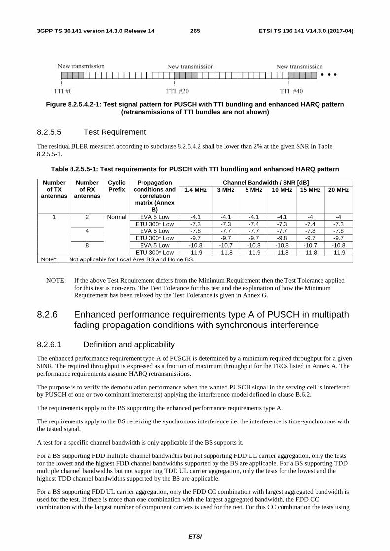
ETSI
ETSI TS 136 141 V14.3.0 (2017-04)2653GPP TS 36.141 version 14.3.0 Release 14
Figure 8.2.5.4.2-1: Test signal pattern for PUSCH with TTI bundling and enhanced HARQ pattern (retransmissions of TTI bundles are not shown)
8.2.5.5 Test Requirement
The residual BLER measured according to subclause 8.2.5.4.2 shall be lower than 2% at the given SNR in Table 8.2.5.5-1.
Table 8.2.5.5-1: Test requirements for PUSCH with TTI bundling and enhanced HARQ pattern
Number of TX
antennas
Number of RX
antennas
Cyclic Prefix
Propagation conditions and
correlation matrix (Annex
B)
Channel Bandwidth / SNR [dB] 1.4 MHz 3 MHz 5 MHz 10 MHz 15 MHz 20 MHz
1 2 Normal EVA 5 Low -4.1 -4.1 -4.1 -4.1 -4 -4 ETU 300* Low -7.3 -7.3 -7.4 -7.3 -7.4 -7.3
4 EVA 5 Low -7.8 -7.7 -7.7 -7.7 -7.8 -7.8 ETU 300* Low -9.7 -9.7 -9.7 -9.8 -9.7 -9.7
8 EVA 5 Low -10.8 -10.7 -10.8 -10.8 -10.7 -10.8 ETU 300* Low -11.9 -11.8 -11.9 -11.8 -11.8 -11.9
Note*: Not applicable for Local Area BS and Home BS.
NOTE: If the above Test Requirement differs from the Minimum Requirement then the Test Tolerance applied for this test is non-zero. The Test Tolerance for this test and the explanation of how the Minimum Requirement has been relaxed by the Test Tolerance is given in Annex G.
8.2.6 Enhanced performance requirements type A of PUSCH in multipath fading propagation conditions with synchronous interference
8.2.6.1 Definition and applicability
The enhanced performance requirement type A of PUSCH is determined by a minimum required throughput for a given SINR. The required throughput is expressed as a fraction of maximum throughput for the FRCs listed in Annex A. The performance requirements assume HARQ retransmissions.
The purpose is to verify the demodulation performance when the wanted PUSCH signal in the serving cell is interfered by PUSCH of one or two dominant interferer(s) applying the interference model defined in clause B.6.2.
The requirements apply to the BS supporting the enhanced performance requirements type A.
The requirements apply to the BS receiving the synchronous interference i.e. the interference is time-synchronous with the tested signal.
A test for a specific channel bandwidth is only applicable if the BS supports it.
For a BS supporting FDD multiple channel bandwidths but not supporting FDD UL carrier aggregation, only the tests for the lowest and the highest FDD channel bandwidths supported by the BS are applicable. For a BS supporting TDD multiple channel bandwidths but not supporting TDD UL carrier aggregation, only the tests for the lowest and the highest TDD channel bandwidths supported by the BS are applicable.
For a BS supporting FDD UL carrier aggregation, only the FDD CC combination with largest aggregated bandwidth is used for the test. If there is more than one combination with the largest aggregated bandwidth, the FDD CC combination with the largest number of component carriers is used for the test. For this CC combination the tests using

ETSI
ETSI TS 136 141 V14.3.0 (2017-04)2663GPP TS 36.141 version 14.3.0 Release 14
full PRB allocation FRC are conducted on per CC basis and measured by the required SINR levels corresponding to the bandwidths used on the different CCs.
For a BS supporting TDD UL carrier aggregation, only the TDD CC combination with largest aggregated bandwidth is used for the test. If there is more than one combination with the largest aggregated bandwidth, the TDD CC combination with the largest number of component carriers is used for the test. For this CC combination the tests using full PRB allocation FRC are conducted on per CC basis and measured by the required SINR levels corresponding to the bandwidths used on the different CCs.
8.2.6.2 Minimum Requirement
The minimum requirement is in TS 36.104 [2] subclause 8.2.6.1.
8.2.6.3 Test Purpose
The test shall verify the receiver’s ability to achieve throughput on the wanted signal at the presence of one or two dominant interferer(s) as specified in section 8.2.6.4.2, under multipath fading propagation conditions for a given SINR.
8.2.6.4 Method of test
8.2.6.4.1 Initial Conditions
Test environment: Normal, see subclause D.2.
RF channels to be tested: M; see subclause 4.7.
1) Connect the BS tester generating the wanted signal, interference signal(s), multipath fading simulators and AWGN generators to all BS antenna connectors for diversity reception via a combining network as shown in Annex I.3.7.
2) Interconnect attenuators for relative power setting purposes for all transmitting branches (wanted signal and all interferers, separately).
8.2.6.4.2 Procedure
1) Adjust the AWGN generator, according to the channel bandwidth, defined in Table 8.2.6.4.2-1.
Table 8.2.6.4.2-1: AWGN power level at the BS input
Channel bandwidth [MHz] AWGN power level 1.4 -92.7dBm / 1.08MHz 3 -88.7dBm / 2.7MHz 5 -86.5dBm / 4.5MHz
10 -83.5dBm / 9MHz 15 -81.7dBm / 13.5MHz 20 -80.4dBm / 18MHz
2) The characteristics of the wanted signal and the interferer(s) shall be configured according to the corresponding UL reference measurement channel defined in annex A and the test parameters in Table 8.2.6.4.2-2.

ETSI
ETSI TS 136 141 V14.3.0 (2017-04)2673GPP TS 36.141 version 14.3.0 Release 14
Table 8.2.6.4.2-2: Test parameters for enhanced performance requirement type A
Parameter Unit Tested signal Interferer 1 (Note 1 )
Interferer 2 (Note 1 )
Maximum number of HARQ transmissions 4 N/A N/A
RV sequence 0, 2, 3, 1, 0, 2, 3, 1 N/A N/A
DIP (Note 2) Set 1 dB N/A -1.11 -10.91
Set 2 dB N/A -0.43 -13.78
Cell Id 0 1 2
Interference model N/A As specified in clause B.6.2
As specified in clause B.6.2
Cyclic Prefix Normal Uplink-downlink allocation for TDD Configuration 1 (2:2)
Demodulation reference signal for PUSCH ssΔ =0, (1)
DMRSn =0, (2)DMRS,0n =0
Group hopping and sequence hopping are disabled. Note 1: One explicit interferer, i.e., interferer 1, is modelled for tests with 2 RX antennas. Two explicit
interferers are modelled for tests with 4 or 8 RX antennas. Note 2: The respective received energy of each interferer relative to ´N is defined by its associated DIP
value as specified in clause B.6.1. DIP set 1 and set 2 are derived respectively in homogeneous and heterogeneous network scenarios.
Note 3: All cells are time-synchronous.
3) The multipath fading emulators shall be configured according to the corresponding channel model defined in annex B.
4) Adjust the equipment so that required SINR specified in Table 8.2.6.5-1 to 8.2.6.5-6 is achieved at the BS input.
5) For each of the reference channels in Table 8.2.6.5-1 to 8.2.6.5-6 applicable for the base station, measure the throughput, according to annex E.
8.2.6.5 Test Requirement
The throughput measured according to subclause 8.2.6.4.2 shall not be below the limits for the SINR levels specified in Table 8.2.6.5-1 to Table 8.2.6.5-6.
Table 8.2.6.5-1: Enhanced performance requirement type A for PUSCH, 1.4MHz Channel Bandwidth
Number of TX
antennas (Note 1)
Number of RX
antennas (Note 1)
Propagation conditions and correlation matrix (Annex B) (Note 2)
DIP set
FRC (Annex
A)
Fraction of maximum
throughput
SINR [dB]
(Note 3) Tested signal
Interferer 1 Interferer 2
1 2 EPA 5 Low ETU 5 Low N/A Set 2 A12-1 70% -4.2 EVA 70 Low ETU 70 Low N/A Set 1* A12-1 70% -1.4
4 EPA 5 Low ETU 5 Low ETU 5 Low Set 2 A13-1 70% -3.5 EVA 70 Low ETU 70 Low ETU 70 Low Set 1* A13-1 70% 0.5
8 EPA 5 Low ETU 5 Low ETU 5 Low Set 2 A4-3 70% -4.1 EVA 70 Low ETU 70 Low ETU 70 Low Set 1* A4-3 70% 0.6
Note*: Not applicable for Local Area BS and Home BS. Note 1: Antenna configuration applies for each of the tested signal, interferer 1 and interferer 2. Note 2: The propagation conditions for the tested signal, interferer 1and interferer 2 are statistically independent.

ETSI
ETSI TS 136 141 V14.3.0 (2017-04)2683GPP TS 36.141 version 14.3.0 Release 14
Table 8.2.6.5-2: Enhanced performance requirement type A for PUSCH, 3 MHz Channel Bandwidth
Number of TX
antennas (Note 1)
Number of RX
antennas (Note 1)
Propagation conditions and correlation matrix (Annex B) (Note 2)
DIP set
FRC (Annex
A)
Fraction of maximum
throughput
SINR [dB]
(Note 3) Tested signal
Interferer 1 Interferer 2
1 2 EPA 5 Low ETU 5 Low N/A Set 2 A12-2 70% -4.4 EVA 70 Low ETU 70 Low N/A Set 1* A12-2 70% -1.7
4 EPA 5 Low ETU 5 Low ETU 5 Low Set 2 A13-2 70% -3.8 EVA 70 Low ETU 70 Low ETU 70 Low Set 1* A13-2 70% 0.5
8 EPA 5 Low ETU 5 Low ETU 5 Low Set 2 A4-4 70% -4.0 EVA 70 Low ETU 70 Low ETU 70 Low Set 1* A4-4 70% 0.5
Note*: Not applicable for Local Area BS and Home BS. Note 1: Antenna configuration applies for each of the tested signal, interferer 1 and interferer 2. Note 2: The propagation conditions for the tested signal, interferer 1 and interferer 2 are statistically independent.
Table 8.2.6.5-3: Enhanced performance requirement type A for PUSCH, 5 MHz Channel Bandwidth
Number of TX
antennas (Note 1)
Number of RX
antennas (Note 1)
Propagation conditions and correlation matrix (Annex B) (Note 2) DIP
set
FRC (Annex
A)
Fraction of maximum
throughput
SINR [dB]
(Note 3) Tested signal Interferer 1 Interferer 2
1 2 EPA 5 Low ETU 5 Low N/A Set 2 A12-3 70% -4.5 EVA 70 Low ETU 70 Low N/A Set 1* A12-3 70% -1.9
4 EPA 5 Low ETU 5 Low ETU 5 Low Set 2 A13-3 70% -3.5 EVA 70 Low ETU 70 Low ETU 70 Low Set 1* A13-3 70% 0.7
8 EPA 5 Low ETU 5 Low ETU 5 Low Set 2 A4-5 70% -4.1 EVA 70 Low ETU 70 Low ETU 70 Low Set 1* A4-5 70% 0.1
Note*: Not applicable for Local Area BS and Home BS. Note 1: Antenna configuration applies for each of the tested signal, interferer 1 and interferer 2. Note 2: The propagation conditions for the tested signal, interferer 1 and interferer 2 are statistically independent.
Table 8.2.6.5-4: Enhanced performance requirement type A for PUSCH, 10 MHz Channel Bandwidth
Number of TX
antennas (Note 1)
Number of RX
antennas (Note 1)
Propagation conditions and correlation matrix (Annex B) (Note 2)
DIP set
FRC (Annex
A)
Fraction of maximum
throughput
SINR [dB]
(Note 3) Tested signal
Interferer 1 Interferer 2
1 2 EPA 5 Low ETU 5 Low N/A Set 2 A12-4 70% -4.8 EVA 70 Low ETU 70 Low N/A Set 1* A12-4 70% -2.1
4 EPA 5 Low ETU 5 Low ETU 5 Low Set 2 A13-4 70% -3.6 EVA 70 Low ETU 70 Low ETU 70 Low Set 1* A13-4 70% 0.5
8 EPA 5 Low ETU 5 Low ETU 5 Low Set 2 A4-6 70% -3.9 EVA 70 Low ETU 70 Low ETU 70 Low Set 1* A4-6 70% 0.4
Note*: Not applicable for Local Area BS and Home BS. Note 1: Antenna configuration applies for each of the tested signal, interferer 1 and interferer 2. Note 2: The propagation conditions for the tested signal, interferer 1 and interferer 2 are statistically independent.

ETSI
ETSI TS 136 141 V14.3.0 (2017-04)2693GPP TS 36.141 version 14.3.0 Release 14
Table 8.2.6.5-5 Enhanced performance requirement type A for PUSCH, 15 MHz Channel Bandwidth
Number of TX
antennas (Note 1)
Number of RX
antennas (Note 1)
Propagation conditions and correlation matrix (Annex B) (Note 2)
DIP set
FRC (Annex
A)
Fraction of maximum
throughput
SINR [dB]
(Note 3) Tested signal
Interferer 1 Interferer 2
1 2 EPA 5 Low ETU 5 Low N/A Set 2 A12-5 70% -4.9 EVA 70 Low ETU 70 Low N/A Set 1* A12-5 70% -2.1
4 EPA 5 Low ETU 5 Low ETU 5 Low Set 2 A13-5 70% -3.4 EVA 70 Low ETU 70 Low ETU 70 Low Set 1* A13-5 70% 0.6
8 EPA 5 Low ETU 5 Low ETU 5 Low Set 2 A4-7 70% -3.9 EVA 70 Low ETU 70 Low ETU 70 Low Set 1* A4-7 70% 0.3
Note*: Not applicable for Local Area BS and Home BS. Note 1: Antenna configuration applies for each of the tested signal, interferer 1 and interferer 2. Note 2: The propagation conditions for the tested signal, interferer 1 and interferer 2 are statistically independent.
Table 8.2.6.5-6 Enhanced performance requirement type A for PUSCH, 20 MHz Channel Bandwidth
Number of TX
antennas (Note 1)
Number of RX
antennas (Note 1)
Propagation conditions and correlation matrix (Annex B) (Note 2)
DIP set
FRC (Annex
A)
Fraction of maximum
throughput
SINR [dB]
(Note 3) Tested signal
Interferer 1 Interferer 2
1 2 EPA 5 Low ETU 5 Low N/A Set 2 A12-6 70% -5.1 EVA 70 Low ETU 70 Low N/A Set 1* A12-6 70% -2.4
4 EPA 5 Low ETU 5 Low ETU 5 Low Set 2 A13-6 70% -3.9 EVA 70 Low ETU 70 Low ETU 70 Low Set 1* A13-6 70% 0.2
8 EPA 5 Low ETU 5 Low ETU 5 Low Set 2 A4-8 70% -4.0 EVA 70 Low ETU 70 Low ETU 70 Low Set 1* A4-8 70% 0.5
Note*: Not applicable for Local Area BS and Home BS. Note 1: Antenna configuration applies for each of the tested signal, interferer 1 and interferer 2. Note 2: The propagation conditions for the tested signal, interferer 1 and interferer 2 are statistically independent.
NOTE: If the above Test Requirement differs from the Minimum Requirement then the Test Tolerance applied for this test is non-zero. The Test Tolerance for this test and the explanation of how the Minimum Requirement has been relaxed by the Test Tolerance is given in Annex G.
8.2.6A Enhanced performance requirements type A of PUSCH in multipath fading propagation conditions with asynchronous interference
8.2.6A.1 Definition and applicability
The enhanced performance requirement type A of PUSCH is determined by a minimum required throughput for a given SINR. The required throughput is expressed as a fraction of maximum throughput for the FRCs listed in Annex A. The performance requirements assume HARQ retransmissions.
The purpose is to verify the demodulation performance when the wanted PUSCH signal in the serving cell is interfered by PUSCH of two interferers from the same interfering cell, applying the interference model defined in clause B.6.3.
The requirements apply to the BS supporting the enhanced performance requirements type A.
The requirements apply to the BS receiving the asynchronous interference i.e. the interference is time-asynchronous with the tested signal.
A test for a specific channel bandwidth is only applicable if the BS supports it.
For a BS supporting FDD multiple channel bandwidths but not supporting FDD UL carrier aggregation, only the tests for the lowest and the highest FDD channel bandwidths supported by the BS are applicable. For a BS supporting TDD multiple channel bandwidths but not supporting TDD UL carrier aggregation, only the tests for the lowest and the highest TDD channel bandwidths supported by the BS are applicable.
For a BS supporting FDD UL carrier aggregation, only the FDD CC combination with largest aggregated bandwidth is used for the test. If there is more than one combination with the largest aggregated bandwidth, the FDD CC

ETSI
ETSI TS 136 141 V14.3.0 (2017-04)2703GPP TS 36.141 version 14.3.0 Release 14
combination with the largest number of component carriers is used for the test. For this CC combination the tests using full PRB allocation FRC are conducted on per CC basis and measured by the required SINR levels corresponding to the bandwidths used on the different CCs.
For a BS supporting TDD UL carrier aggregation, only the TDD CC combination with largest aggregated bandwidth is used for the test. If there is more than one combination with the largest aggregated bandwidth, the TDD CC combination with the largest number of component carriers is used for the test. For this CC combination the tests using full PRB allocation FRC are conducted on per CC basis and measured by the required SINR levels corresponding to the bandwidths used on the different CCs.
8.2.6A.2 Minimum Requirement
The minimum requirement is in TS 36.104 [2] subclause 8.2.6A.1.
8.2.6A.3 Test Purpose
The test shall verify the receiver’s ability to achieve throughput on the wanted signal at the presence of two dominant interferers as specified in section 8.2.6A.4.2, under multipath fading propagation conditions for a given SINR.
8.2.6A.4 Method of test
8.2.6A.4.1 Initial Conditions
Test environment: Normal, see subclause D.2.
RF channels to be tested: M; see subclause 4.7.
1) Connect the BS tester generating the wanted signal, interference signals, multipath fading simulators and AWGN generators to all BS antenna connectors for diversity reception via a combining network as shown in Annex I.3.7.
2) Interconnect attenuators for relative power setting purposes for all transmitting branches (wanted signal and all interferers, separately).
8.2.6A.4.2 Procedure
1) Adjust the AWGN generator, according to the channel bandwidth, defined in Table 8.2.6A.4.2-1.
Table 8.2.6A.4.2-1: AWGN power level at the BS input
Channel bandwidth [MHz] AWGN power level 1.4 -92.7dBm / 1.08MHz 3 -88.7dBm / 2.7MHz 5 -86.5dBm / 4.5MHz
10 -83.5dBm / 9MHz 15 -81.7dBm / 13.5MHz 20 -80.4dBm / 18MHz
2) The characteristics of the wanted signal and the interferers shall be configured according to the corresponding UL reference measurement channel defined in annex A and the test parameters in Table 8.2.6A.4.2-2.

ETSI
ETSI TS 136 141 V14.3.0 (2017-04)2713GPP TS 36.141 version 14.3.0 Release 14
Table 8.2.6A.4.2-2: Test parameters for enhanced performance requirement type A
Parameter Unit Tested signal Interferer 1-1 (Note 1 )
Interferer 1-2 (Note 1 )
Maximum number of HARQ transmissions 4 N/A N/A
RV sequence 0, 2, 3, 1, 0, 2, 3, 1 N/A N/A
DIP (Note 2) dB N/A -0.43 -0.43
Cell Id 0 1 1
Interference model N/A As specified in clause B.6.3
As specified in clause B.6.3
Cyclic Prefix Normal
Demodulation reference signal for PUSCH ssΔ =0, (1)
DMRSn =0, (2)DMRS,0n =0
Group hopping and sequence hopping are disabled. Note 1: Interferer 1-1 and interferer 1-2 are connected to the same cell and configured to transmit
respectively in the even subframes and odd subframes. Note 2: The respective received energy of each interferer relative to ´N is defined by its associated DIP
value as specified in clause B.6.1. Note 3: The transmissions of both interferer 1-1 and interferer 1-2 are delayed with respect to the tested
signal by 0.33 ms.
3) The multipath fading emulators shall be configured according to the corresponding channel model defined in annex B.
4) Adjust the equipment so that required SINR specified in Table 8.2.6A.5-1 to 8.2.6A.5-6 is achieved at the BS input.
5) For each of the reference channels in Table 8.2.6A.5-1 to 8.2.6A.5-6 applicable for the base station, measure the throughput, according to annex E.
8.2.6A.5 Test Requirement
The throughput measured according to subclause 8.2.6A.4.2 shall not be below the limits for the SINR levels specified in Table 8.2.6A.5-1 to Table 8.2.6A.5-6.
Table 8.2.6A.5-1 Enhanced performance requirement type A for PUSCH, 1.4MHz Channel Bandwidth
Number of TX
antennas (Note 1)
Number of RX
antennas (Note 1)
Propagation conditions and correlation matrix (Annex B) (Note 2)
FRC (Annex A)
Fraction of maximum
throughput
SINR [dB]
Tested signal Interferer 1-1 Interferer 1-2
1 2 EPA 5 Low ETU 5 Low ETU 5 Low A12-1 70% -1.7 4 EPA 5 Low ETU 5 Low ETU 5 Low A13-1 70% -0.8 8 EPA 5 Low ETU 5 Low ETU 5 Low A4-3 70% -1.6
Note 1: Antenna configuration applies for each of the tested signal, interferer 1-1 and interferer 1-2. Note 2: The propagation conditions for the tested signal, interferer 1-1 and interferer 1-2 are statistically
independent.
Table 8.2.6A.5-2 Enhanced performance requirement type A for PUSCH, 3 MHz Channel Bandwidth
Number of TX
antennas (Note 1)
Number of RX
antennas (Note 1)
Propagation conditions and correlation matrix (Annex B) (Note 2)
FRC (Annex A)
Fraction of maximum
throughput
SINR [dB]
Tested signal Interferer 1-1 Interferer 1-2
1 2 EPA 5 Low ETU 5 Low ETU 5 Low A12-2 70% -1.9 4 EPA 5 Low ETU 5 Low ETU 5 Low A13-2 70% -1.0 8 EPA 5 Low ETU 5 Low ETU 5 Low A4-4 70% -1.6
Note 1: Antenna configuration applies for each of the tested signal, interferer 1-1 and interferer 1-2. Note 2: The propagation conditions for the tested signal, interferer 1-1 and interferer 1-2 are statistically
independent.
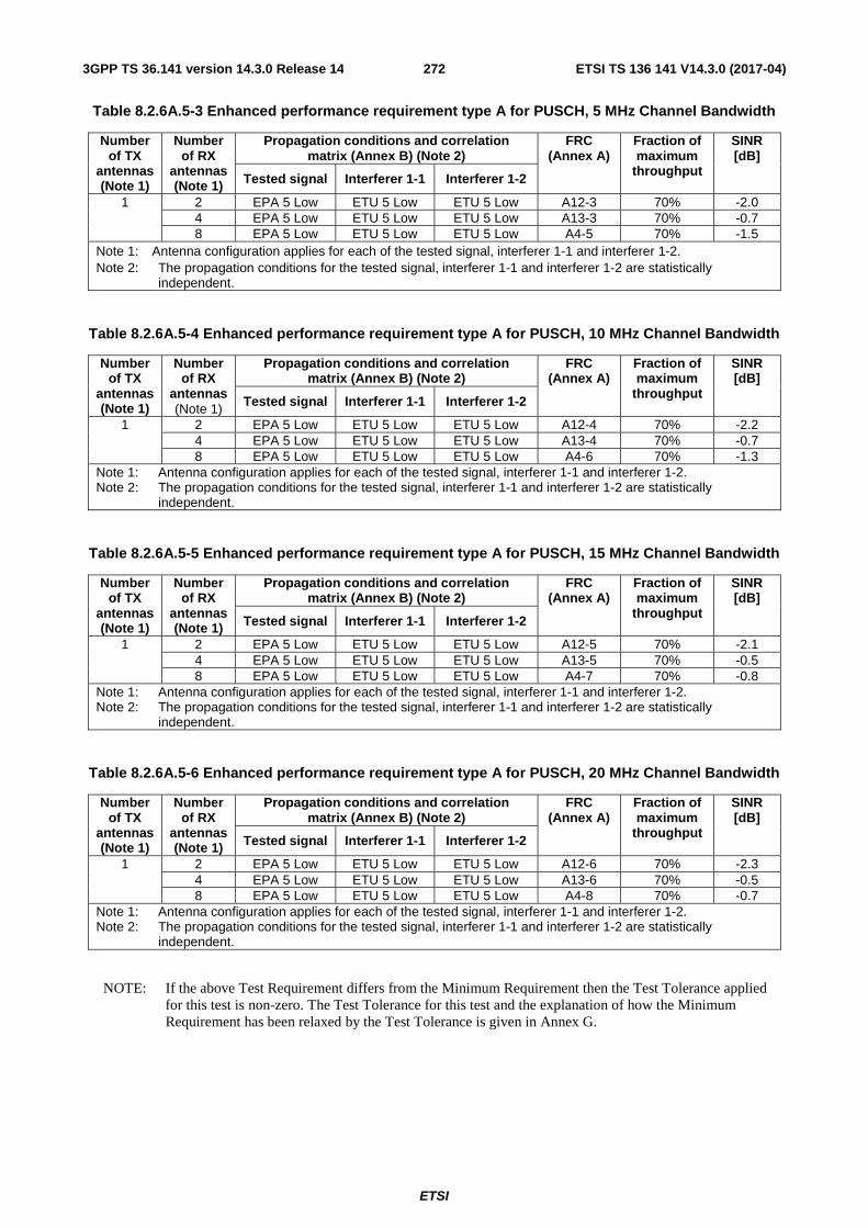
ETSI
ETSI TS 136 141 V14.3.0 (2017-04)2723GPP TS 36.141 version 14.3.0 Release 14
Table 8.2.6A.5-3 Enhanced performance requirement type A for PUSCH, 5 MHz Channel Bandwidth
Number of TX
antennas (Note 1)
Number of RX
antennas (Note 1)
Propagation conditions and correlation matrix (Annex B) (Note 2)
FRC (Annex A)
Fraction of maximum
throughput
SINR [dB]
Tested signal Interferer 1-1 Interferer 1-2
1 2 EPA 5 Low ETU 5 Low ETU 5 Low A12-3 70% -2.0 4 EPA 5 Low ETU 5 Low ETU 5 Low A13-3 70% -0.7 8 EPA 5 Low ETU 5 Low ETU 5 Low A4-5 70% -1.5
Note 1: Antenna configuration applies for each of the tested signal, interferer 1-1 and interferer 1-2. Note 2: The propagation conditions for the tested signal, interferer 1-1 and interferer 1-2 are statistically
independent.
Table 8.2.6A.5-4 Enhanced performance requirement type A for PUSCH, 10 MHz Channel Bandwidth
Number of TX
antennas (Note 1)
Number of RX
antennas (Note 1)
Propagation conditions and correlation matrix (Annex B) (Note 2)
FRC (Annex A)
Fraction of maximum
throughput
SINR [dB]
Tested signal Interferer 1-1 Interferer 1-2
1 2 EPA 5 Low ETU 5 Low ETU 5 Low A12-4 70% -2.2 4 EPA 5 Low ETU 5 Low ETU 5 Low A13-4 70% -0.7 8 EPA 5 Low ETU 5 Low ETU 5 Low A4-6 70% -1.3
Note 1: Antenna configuration applies for each of the tested signal, interferer 1-1 and interferer 1-2. Note 2: The propagation conditions for the tested signal, interferer 1-1 and interferer 1-2 are statistically
independent.
Table 8.2.6A.5-5 Enhanced performance requirement type A for PUSCH, 15 MHz Channel Bandwidth
Number of TX
antennas (Note 1)
Number of RX
antennas (Note 1)
Propagation conditions and correlation matrix (Annex B) (Note 2)
FRC (Annex A)
Fraction of maximum
throughput
SINR [dB]
Tested signal Interferer 1-1 Interferer 1-2
1 2 EPA 5 Low ETU 5 Low ETU 5 Low A12-5 70% -2.1 4 EPA 5 Low ETU 5 Low ETU 5 Low A13-5 70% -0.5 8 EPA 5 Low ETU 5 Low ETU 5 Low A4-7 70% -0.8
Note 1: Antenna configuration applies for each of the tested signal, interferer 1-1 and interferer 1-2. Note 2: The propagation conditions for the tested signal, interferer 1-1 and interferer 1-2 are statistically
independent.
Table 8.2.6A.5-6 Enhanced performance requirement type A for PUSCH, 20 MHz Channel Bandwidth
Number of TX
antennas (Note 1)
Number of RX
antennas (Note 1)
Propagation conditions and correlation matrix (Annex B) (Note 2)
FRC (Annex A)
Fraction of maximum
throughput
SINR [dB]
Tested signal Interferer 1-1 Interferer 1-2
1 2 EPA 5 Low ETU 5 Low ETU 5 Low A12-6 70% -2.3 4 EPA 5 Low ETU 5 Low ETU 5 Low A13-6 70% -0.5 8 EPA 5 Low ETU 5 Low ETU 5 Low A4-8 70% -0.7
Note 1: Antenna configuration applies for each of the tested signal, interferer 1-1 and interferer 1-2. Note 2: The propagation conditions for the tested signal, interferer 1-1 and interferer 1-2 are statistically
independent.
NOTE: If the above Test Requirement differs from the Minimum Requirement then the Test Tolerance applied for this test is non-zero. The Test Tolerance for this test and the explanation of how the Minimum Requirement has been relaxed by the Test Tolerance is given in Annex G.

ETSI
ETSI TS 136 141 V14.3.0 (2017-04)2733GPP TS 36.141 version 14.3.0 Release 14
8.2.7 Performance requirements of PUSCH in multipath fading propagation conditions transmission on single antenna port for supporting Cat-M1 UEs
8.2.7.1 Definition and applicability
The performance requirement of PUSCH is determined by a minimum required throughput for a given SNR. The required throughput is expressed as a fraction of maximum throughput for the FRCs listed in Annex A. The performance requirements assume HARQ re-transmissions.
The tests for CEModeA defined in Section 8.2.7 are applicable only to the base stations supporting Cat-M1 UEs configured with CEModeA. The tests for CEModeB defined in Section 8.2.7 are applicable only to the base stations supporting Cat-M1 UEs configured with CEModeB.
A test for a specific channel bandwidth is only applicable if the BS supports it. For a BS supporting FDD multiple channel bandwidths, only the tests for the lowest and the highest FDD channel bandwidths supported by the BS are applicable. For a BS supporting TDD multiple channel bandwidths, only the tests for the lowest and the highest TDD channel bandwidths supported by the BS are applicable.
8.2.7.2 Minimum Requirement
The minimum requirement is in TS 36.104 [2] subclause 8.2.7.
8.2.7.3 Test Purpose
The test shall verify the receiver’s ability to achieve throughput under multipath fading propagation conditions for a given SNR.
8.2.7.4 Method of test
8.2.7.4.1 Initial Conditions
Test environment: Normal, see subclause D.2.
RF channels to be tested: M; see subclause 4.7.
1) Connect the BS tester generating the wanted signal, multipath fading simulators and AWGN generators to all BS antenna connectors for diversity reception via a combining network as shown in Annex I.3.2.
8.2.7.4.2 Procedure
1) Adjust the AWGN generator, according to the channel bandwidth, defined in Table 8.2.7.4.2-1.
Table 8.2.7.4.2-1: AWGN power level at the BS input
Channel bandwidth [MHz] AWGN power level 1.4 -92.7dBm / 1.08MHz 3 -88.7dBm / 2.7MHz 5 -86.5dBm / 4.5MHz
10 -83.5dBm / 9MHz 15 -81.7dBm / 13.5MHz 20 -80.4dBm / 18MHz
2) The characteristics of the wanted signal shall be configured according to the corresponding UL reference measurement channel defined in annex A and the test parameters in Table 8.2.7.4.2-2. For reference channels using 1 resource block the resource block in the middle of the channel bandwidth shall be used. In case the number of resource blocks in the channel bandwidth are even the one in the middle with lower number is to be used for testing.

ETSI
ETSI TS 136 141 V14.3.0 (2017-04)2743GPP TS 36.141 version 14.3.0 Release 14
Table 8.2.7.4.2-2: Test parameters for testing PUSCH
Parameter unit CEMode A CEMode B Maximum number of HARQ
transmissions 4 2
RV sequences
0, 2, 3, 1, 0, 2, 3, 1 FDD: 0, 0, 0, 0, 2, 2, 2, 2, 3, 3, 3, 3, 1, 1, 1, 1
TDD: 0, 0, 0, 0, 0, 2, 2, 2, 2, 2, 3, 3, 3, 3, 3, 1, 1, 1, 1,1
Number of PUSCH repetitions 8 256 Frequency hopping ON ON
Frequency hopping interval subframes 4: FDD 5: TDD
4: FDD 5: TDD
Note 1: Guard period shall be created according to TS36.211, 5.2.5 [12]
3) The multipath fading emulators shall be configured according to the corresponding channel model defined in annex B.
4) Adjust the equipment so that required SNR specified in Table 8.2.7.5-1 to 8.2.7.5-2 is achieved at the BS input.
5) For each of the reference channels in Table 8.2.7.5-1 to 8.2.7.5-2 applicable for the base station, measure the throughput, according to annex E.
8.2.7.5 Test Requirement
The throughput measured according to subclause 8.2.7.4.2 shall not be below the limits for the SNR levels specified in Table 8.2.7.5-1 for CEMode A tests and not be below the limits for the SNR levels specified in Table 8.2.7.5-2 for CEMode B tests.
Table 8.2.7.5-1 Minimum requirements for PUSCH for CEMode A
Number of TX antennas
Number of RX antennas
Channel Bandwidth
(MHz)
Propagation conditions and correlation matrix
(Annex B)
FRC (Annex
A)
Fraction of maximum
throughput
SNR [dB]
1 2 3 EPA 5Hz Low A3-2 70% -5.6 1 2 5 EPA 5Hz Low A3-2 70% -6.0 1 2 10 EPA 5Hz Low A3-2 70% -6.3 1 2 15 EPA 5Hz Low A3-2 70% -6.3 1 2 20 EPA 5Hz Low A3-2 70% -6.4
Table 8.2.7.5-2 Minimum requirements for PUSCH for CEMode B
Number of TX antennas
Number of RX antennas
Channel Bandwidth
(MHz)
Propagation conditions and correlation matrix
(Annex B)
FRC (Annex
A)
Fraction of maximum
throughput
SNR [dB]
1 2 3 ETU 1Hz Low A3-1 70% -14.4 1 2 5 ETU 1Hz Low A3-1 70% -14.6 1 2 10 ETU 1Hz Low A3-1 70% -14.7 1 2 15 ETU 1Hz Low A3-1 70% -14.5
1 2 20 ETU 1Hz Low A3-1 70% -14.6
NOTE: If the above Test Requirement differs from the Minimum Requirement then the Test Tolerance applied for this test is non-zero. The Test Tolerance for this test and the explanation of how the Minimum Requirement has been relaxed by the Test Tolerance is given in Annex G.

ETSI
ETSI TS 136 141 V14.3.0 (2017-04)2753GPP TS 36.141 version 14.3.0 Release 14
8.3 Performance requirements for PUCCH
8.3.1 ACK missed detection for single user PUCCH format 1a transmission on single antenna port
8.3.1.1 Definition and applicability
The performance requirement of single user PUCCH for ACK missed detection is determined by the two parameters: probability of false detection of the ACK and the probability of detection of ACK. The performance is measured by the required SNR at probability of detection equal to 0.99. The probability of false detection of the ACK shall be 0.01 or less.
The probability of false detection of the ACK is defined as a conditional probability of erroneous detection of the ACK when input is only noise.
The probability of detection of ACK is defined as conditional probability of detection of the ACK when the signal is present.
The test is applicable to all BS. A test for a specific channel bandwidth is only applicable if the BS supports it.
For a BS supporting multiple channel bandwidths only the tests for the lowest and the highest channel bandwidth supported by the BS are applicable.
ACK/NACK repetitions are disabled for PUCCH transmission.
8.3.1.2 Minimum Requirement
The minimum requirement is in TS 36.104 [2] subclause 8.3.1.1 and 8.3.2.1.
8.3.1.3 Test purpose
The test shall verify the receiver’s ability to detect ACK under multipath fading propagation conditions for a given SNR.
8.3.1.4 Method of test
8.3.1.4.1 Initial Conditions
Test environment: Normal, see subclause D.2.
RF channels to be tested: M; see subclause 4.7
1) Connect the BS tester generating the wanted signal, multipath fading simulators and AWGN generators to all BS antenna connectors for diversity reception via a combining network as shown in Annex I.3.2.
8.3.1.4.2 Procedure
1) Adjust the AWGN generator, according to the channel bandwidth defined in Table 8.3.1.4.2-1.
Table 8.3.1.4.2-1: AWGN power level at the BS input
Channel bandwidth [MHz] AWGN power level 1.4 -89.7 dBm / 1.08MHz 3 -85.7 dBm / 2.7MHz 5 -83.5 dBm / 4.5MHz
10 -80.5 dBm / 9MHz 15 -78.7 dBm / 13.5MHz 20 -77.4 dBm / 18MHz

ETSI
ETSI TS 136 141 V14.3.0 (2017-04)2763GPP TS 36.141 version 14.3.0 Release 14
2) The characteristics of the wanted signal shall be configured according to TS 36.211 [12].
3) The multipath fading emulators shall be configured according to the corresponding channel model defined in Annex B.
4) Adjust the equipment so that the SNR specified in Table 8.3.1.5-1 is achieved at the BS input during the ACK transmissions.
5) The signal generator sends a test pattern with the pattern outlined in figure 8.3.1.4.2-1. The following statistics are kept: the number of ACKs detected in the idle periods and the number of missed ACKs.
ACK ACK ACK
Figure 8.3.1.4.2-1: Test signal pattern for single user PUCCH format 1a demodulation tests
8.3.1.5 Test Requirement
The fraction of falsely detected ACKs shall be less than 1% and the fraction of correctly detected ACKs shall be larger than 99% for the SNR listed in Table 8.3.1.5-1.
Table 8.3.1.5-1: Required SNR for single user PUCCH format 1a demodulation tests
Number
of TX
antennas
Number of RX
antennas
Cyclic Prefix
Propagation conditions
and
correlation matrix (Annex B)
Channel Bandwidth / SNR [dB]
1.4 MHz
3 MHz 5 MHz
10 MHz
15 MHz
20 MHz
1 2 Normal EPA 5 Low -1.9 -3.3 -4.2 -4.8 -4.7 -4.5
EVA 5 Low -3.9 -4.5 -4.5 -4.4 -4.5 -4.5
EVA 70 Low -4.3 -4.6 -4.6 -4.5 -4.6 -4.5
ETU 300* Low -4.4 -4.5 -4.3 -4.4 -4.6 -4.6
Extended ETU 70* Low -3.6 -3.7 -3.5 -3.7 -3.6 -3.7
4 Normal EPA 5 Low -7.3 -7.8 -8.1 -8.3 -8.3 -8.4
EVA 5 Low -8.2 -8.5 -8.5 -8.2 -8.3 -8.3
EVA 70 Low -8.3 -8.4 -8.4 -8.2 -8.4 -8.2
ETU 300* Low -8.1 -8.3 -8.1 -8.1 -8.3 -8.2
Extended ETU 70* Low -7.3 -7.5 -7.3 -7.5 -7.4 -7.4
8 Normal EPA 5 Low -10.6 -10.9 -11.6 -11.7 -11.7 -11.7 EVA 5 Low -11.4 -11.4 -11.5 -11.5 -11.7 -11.6
EVA 70 Low -11.4 -11.5 -11.6 -11.5 -11.7 -11.5 ETU 300* Low -11 -11 -11 -11.2 -11 -11.2
Extended ETU 70* Low -9.9 -10.1 -10 -10.1 -10 -10 Note*: Not applicable for Local Area BS and Home BS.
NOTE: If the above Test Requirement differs from the Minimum Requirement then the Test Tolerance applied for this test is non-zero. The Test Tolerance for this test and the explanation of how the Minimum Requirement has been relaxed by the Test Tolerance is given in Annex G.

ETSI
ETSI TS 136 141 V14.3.0 (2017-04)2773GPP TS 36.141 version 14.3.0 Release 14
8.3.2 CQI performance requirements for PUCCH format 2 transmission on single antenna port
8.3.2.1 Definition and applicability
The performance requirement of PUCCH format 2 for CQI is determined by the block error probability (BLER) of CQI. The performance is measured by the required SNR at BLER of 1%.
The CQI block error probability is defined as the conditional probability of incorrectly decoding the CQI information when the CQI information is sent. All CQI information shall be decoded (no exclusion due to DTX).
The test is applicable to all BS. A test for a specific channel bandwidth is only applicable if the BS supports it.
For a BS supporting multiple channel bandwidths only the tests for the lowest and the highest channel bandwidths supported by the BS are applicable.
8.3.2.2 Minimum Requirement
The minimum requirement is in TS 36.104 [2] subclause 8.3.3.1.
8.3.2.3 Test purpose
The test shall verify the receiver’s ability to detect CQI under multipath fading propagation conditions for a given SNR.
8.3.2.4 Method of test
8.3.2.4.1 Initial Conditions
Test environment: Normal, see subclause D.2.
RF channels to be tested: M; see subclause 4.7
1) Connect the BS tester generating the wanted signal, multipath fading simulators and AWGN generators to all BS antenna connectors for diversity reception via a combining network as shown in Annex I.3.2.
8.3.2.4.2 Procedure
1) Adjust the AWGN generator, according to the channel bandwidth defined in Table 8.3.2.4.2-1.
Table 8.3.2.4.2-1: AWGN power level at the BS input
Channel bandwidth [MHz] AWGN power level 1.4 -89.7 dBm / 1.08MHz 3 -85.7 dBm / 2.7MHz 5 -83.5 dBm / 4.5MHz
10 -80.5 dBm / 9MHz 15 -78.7 dBm / 13.5MHz 20 -77.4 dBm / 18MHz
2) The characteristics of the wanted signal shall be configured according to TS 36.211. The CQI information bit payload per sub-frame is equal to 4 bits.
3) The multipath fading emulators shall be configured according to the corresponding channel model defined in Annex B.
4) Adjust the equipment so that the SNR specified in Table 8.3.2.5-1 is achieved at the BS input during the CQI transmissions.
5) The signal generator sends a test pattern with the pattern outlined in figure 8.3.2.4.2-1. The following statistics are kept: the number of incorrectly decoded CQI.

ETSI
ETSI TS 136 141 V14.3.0 (2017-04)2783GPP TS 36.141 version 14.3.0 Release 14
CQI CQI CQI
Figure 8.3.2.4.2-1: Test signal pattern for PUCCH format 2 demodulation tests
8.3.2.5 Test Requirement
The fraction of incorrectly decoded CQIs shall be less than 1% for the SNR listed in Table 8.3.2.5-1.
Table 8.3.2.5-1: Required SNR for PUCCH format 2 demodulation tests
Number of TX
antennas
Number of RX
antennas
Cyclic Prefix
Propagation conditions
and correlation
matrix (Annex B)
Channel Bandwidth / SNR [dB] 1.4
MHz 3 MHz 5 MHz 10 MHz 15 MHz 20 MHz
1 2 Normal EVA 5* Low -3.1 -3.5 -3.8 -3.4 -3.6 -3.6 ETU 70**
Low -3.3 -3.8 -3.6 -3.8 -3.8 -3.8
Note*: Not applicable for Wide Area BS and Medium Range BS. Note**: Not applicable for Local Area BS and Home BS.
NOTE: If the above Test Requirement differs from the Minimum Requirement then the Test Tolerance applied for this test is non-zero. The Test Tolerance for this test and the explanation of how the Minimum Requirement has been relaxed by the Test Tolerance is given in Annex G.
8.3.3 ACK missed detection for multi user PUCCH format 1a
8.3.3.1 Definition and applicability
The performance requirement of multi user PUCCH for ACK missed detection is determined by the two parameters: probability of false detection of the ACK and the probability of detection of ACK on the wanted signal. The performance is measured by the required SNR at probability of detection equal to 0.99. The probability of false detection of the ACK shall be 0.01 or less. These probabilities are measured on the wanted signal at presence of three interfering signals as specified in section 8.3.3.4.2.
The probability of false detection of the ACK is defined as a conditional probability of erroneous detection of the ACK when input is only noise and the interfering signals are present.
The probability of detection of ACK is defined as conditional probability of detection of the ACK when the signal is present.
The test is applicable to all BS. A test for a specific channel bandwidth is only applicable if the BS supports it.
For a BS supporting multiple channel bandwidths only the tests for the lowest and the highest channel bandwidths supported by the BS are applicable.
Multi user PUCCH test is performed only for 2 Rx antennas, Normal CP and for ETU70 propagation conditions.
ACK/NACK repetitions are disabled for PUCCH transmission.
8.3.3.2 Minimum Requirement
The minimum requirements are in TS 36.104 [2] subclause 8.3.1.1 and 8.3.4.1.
8.3.3.3 Test purpose
The test shall verify the receiver’s ability to detect ACK on the wanted signal at presence of three interfering signals as specified in section 8.3.3.4.2, under multipath fading propagation conditions for a given SNR.

ETSI
ETSI TS 136 141 V14.3.0 (2017-04)2793GPP TS 36.141 version 14.3.0 Release 14
8.3.3.4 Method of test
8.3.3.4.1 Initial Conditions
Test environment: Normal, see subclause D.2.
RF channels to be tested: M; see subclause 4.7.
1) Connect the BS tester generating the wanted and all interfering signals, multipath fading simulators and AWGN generators to both BS antenna connectors for 2Rx diversity reception via a combining network as shown in Annex I.3.3.
2) Interconnect attenuators for relative power setting purposes for all transmitting branches (wanted signal and all interferers, separately).
8.3.3.4.2 Procedure
1) Adjust the AWGN generator, according to the channel bandwidth defined in Table 8.3.3.4.2-1.
Table 8.3.3.4.2-1: AWGN power level at the BS input
Channel bandwidth [MHz] AWGN power level 1.4 -89.7 dBm / 1.08MHz 3 -85.7 dBm / 2.7MHz 5 -83.5 dBm / 4.5MHz
10 -80.5 dBm / 9MHz 15 -78.7 dBm / 13.5MHz 20 -77.4 dBm / 18MHz
2) In multi user PUCCH test, four signals are configured: one wanted signal and three interferers, which are transmitted via separate fading paths using relative power settings presented in Annex A.9.
All signals are transmitted on the same PUCCH resources, with different PUCCH channel indices, as presented in Annex A.9.
The characteristics of the all signals (i.e. wanted and all interferers) shall be configured according to 36.211 [12].
3) The multipath fading emulators shall be configured according to ETU70 propagation conditions defined in Annex B.
4) Adjust the equipment so that the SNR specified in Table 8.3.3.5-1 is achieved at the BS input during the ACK transmissions on the wanted signal.
5) The signal generator sends a test pattern with the pattern outlined in figure 8.3.3.4.2-1. This statement is valid for the wanted PUCCH signal. All interferers are present for all subframes. The following statistics are kept: the number of ACKs detected in the idle periods and the number of missed ACKs on the wanted PUCCH signal.
ACK ACK ACK
Figure 8.3.3.4.2-1: Test signal pattern for multi user PUCCH demodulation tests
8.3.3.5 Test Requirement
The fraction of falsely detected ACKs on the wanted signal shall be less than 1% and the fraction of correctly detected ACKs shall be larger than 99% for the SNR listed in Table 8.3.3.5-1.

ETSI
ETSI TS 136 141 V14.3.0 (2017-04)2803GPP TS 36.141 version 14.3.0 Release 14
Table 8.3.3.5-1: Required SNR for multi user PUCCH demodulation tests
Number of TX
antennas
Number of RX
antennas
Cyclic Prefix
Propagation conditions and
correlation matrix (Annex B)
Channel Bandwidth / SNR [dB] 1.4
MHz 3
MHz 5
MHz 10
MHz 15
MHz 20
MHz
1 2 Normal ETU 70* Low -3.5 -3.8 -3.8 -4.0 -4.0 -3.8
Note*: Not applicable for Local Area BS and Home BS.
NOTE: If the above Test Requirement differs from the Minimum Requirement then the Test Tolerance applied for this test is non-zero. The Test Tolerance for this test and the explanation of how the Minimum Requirement has been relaxed by the Test Tolerance is given in Annex G.
8.3.4 ACK missed detection for PUCCH format 1b with Channel Selection
8.3.4.1 Definition and applicability
The performance requirement of PUCCH format 1b with Channel Selection for ACK missed detection is determined by the two parameters: probability of false detection of the ACK and the probability of detection of ACK. The performance is measured by the required SNR at probability of detection equal to 0.99. The probability of false detection of the ACK shall be 0.01 or less.
The probability of false detection of the ACK is defined as a conditional probability of erroneous detection of the ACK at particular channel when input is only noise.
The probability of detection of ACK is defined as conditional probability of detection of the ACK when the ACK was sent at particular channel.
The test is applicable to all BS. A test for a specific channel bandwidth is only applicable if the BS supports it.
For a BS supporting multiple channel bandwidths only the tests for the lowest and the highest channel bandwidth supported by the BS are applicable.
The number of encoded ACK/NACK bits per sub-frame is equal to 4 bits (AAAA),
ACK/NACK repetitions are disabled for PUCCH transmission.
8.3.4.2 Minimum Requirement
The minimum requirement is in TS 36.104 [2] subclause 8.3.1.1 and 8.3.5.1.
8.3.4.3 Test purpose
The test shall verify the receiver’s ability to detect ACK bits under multipath fading propagation conditions for a given SNR.
8.3.4.4 Method of test
8.3.4.4.1 Initial Conditions
Test environment: Normal, see subclause D.2.
RF channels to be tested: M; see subclause 4.7
1) Connect the BS tester generating the wanted signal, multipath fading simulators and AWGN generators to all BS antenna connectors for diversity reception via a combining network as shown in Annex I.3.2.
8.3.4.4.2 Procedure
1) Adjust the AWGN generator, according to the channel bandwidth defined in Table 8.3.4.4.2-1.

ETSI
ETSI TS 136 141 V14.3.0 (2017-04)2813GPP TS 36.141 version 14.3.0 Release 14
Table 8.3.4.4.2-1: AWGN power level at the BS input
Channel bandwidth [MHz] AWGN power level 10 -80.5 dBm / 9MHz 15 -78.7 dBm / 13.5MHz 20 -77.4 dBm / 18MHz
2) The characteristics of the wanted signal shall be configured according to TS 36.211 [12].
3) The multipath fading emulators shall be configured according to the corresponding channel model defined in Annex B.
4) Adjust the equipment so that the SNR specified in Table 8.3.4.5-1 is achieved at the BS input during the AAAA codeword transmissions.
5) The signal generator sends AAAA codeword in regular time periods. The following statistics are kept: the number of ACK bits falsely detected in the idle periods and the number of missed ACK bits. Each falsely detected ACK bit in the idle periods is accounted as one error for the statistics of false ACK detection, and each missed ACK bit is accounted as one error for the statistics of missed ACK detection.
8.3.4.5 Test Requirement
The fraction of falsely detected ACK bits shall be less than 1% and the fraction of correctly detected ACK bits shall be larger than 99% for the SNR listed in Table 8.3.4.5-1.
Table 8.3.4.5-1: Required SNR for PUCCH format 1b with Channel Selection demodulation tests
Number of TX
antennas
Number of RX
antennas
Cyclic Prefix
Propagation conditions and
correlation matrix (Annex B)
Channel Bandwidth / SNR [dB]
1.4MHz 3MHz 5MHz 10 MHz 15MHz 20MHz
1 2 Normal EPA 5 Low - - - -3.9 -4.0 -4.0 EVA70 Low - - - -3.7 -3.9 -3.9
4 Normal EPA 5 Low - - - -7.8 -7.9 -8.0 EVA70 Low - - - -7.7 -7.9 -7.9
8 Normal EPA 5 Low - - - -11.1 -11.2 -11.2 EVA70 Low - - - -10.9 -11.1 -11.0
NOTE: If the above Test Requirement differs from the Minimum Requirement then the Test Tolerance applied for this test is non-zero. The Test Tolerance for this test and the explanation of how the Minimum Requirement has been relaxed by the Test Tolerance is given in Annex G.
8.3.5 ACK missed detection for PUCCH format 3
8.3.5.1 Definition and applicability
The performance requirement of PUCCH format 3 for ACK missed detection is determined by the two parameters: probability of false detection of the ACK and the probability of detection of ACK. The performance is measured by the required SNR at probability of detection equal to 0.99. The probability of false detection of the ACK shall be 0.01 or less.
The probability of false detection of the ACK is defined as a conditional probability of erroneous detection of the ACK at particular bit position when input is only noise.
The probability of detection of ACK is defined as conditional probability of detection of the ACK when the ACK was sent at particular bit position. Each missed ACK bit is counted as one error.
The test is applicable to all BS. A test for a specific channel bandwidth is only applicable if the BS supports it.
For a BS supporting multiple channel bandwidths only the tests for the lowest and the highest channel bandwidth supported by the BS are applicable.

ETSI
ETSI TS 136 141 V14.3.0 (2017-04)2823GPP TS 36.141 version 14.3.0 Release 14
The number of encoded ACK/NACK bits per sub-frame is defined for two cases as presented below:
- 4AN bits: applicable for FDD and TDD
- 16AN bits : applicable for TDD
ACK/NACK repetitions are disabled for PUCCH transmission. Random codeword selection is assumed.
8.3.5.2 Minimum Requirement
The minimum requirement is in TS 36.104 [2] subclause 8.3.1.1 and 8.3.6.1.
8.3.5.3 Test purpose
The test shall verify the receiver’s ability to detect ACK bits in codeword’s from applicable codebook being randomly selected, under multipath fading propagation conditions for a given SNR.
8.3.5.4 Method of test
8.3.5.4.1 Initial Conditions
Test environment: Normal, see subclause D.2.
RF channels to be tested: M; see subclause 4.7
1) Connect the BS tester generating the wanted signal, multipath fading simulators and AWGN generators to all BS antenna connectors for diversity reception via a combining network as shown in Annex I.3.2.
8.3.5.4.2 Procedure
1) Adjust the AWGN generator, according to the channel bandwidth defined in Table 8.3.5.4.2-1.
Table 8.3.5.4.2-1: AWGN power level at the BS input
Channel bandwidth [MHz] AWGN power level 10 -80.5 dBm / 9MHz 15 -78.7 dBm / 13.5MHz 20 -77.4 dBm / 18MHz
2) The characteristics of the wanted signal shall be configured according to TS 36.211 [12].
3) The multipath fading emulators shall be configured according to the corresponding channel model defined in Annex B.
4) Adjust the equipment so that the SNR specified in Table 8.3.5.5-1 or 8.3.5.5-2 is achieved at the BS input during the codeword’s transmissions.
5) The signal generator sends random codewords from applicable codebook, in regular time periods. The following statistics are kept: the number of ACK bits falsely detected in the idle periods and the number of missed ACK bits. Each falsely detected ACK bit in the idle periods is accounted as one error for the statistics of false ACK detection, and each missed ACK bit is accounted as one error for the statistics of missed ACK detection.
8.3.5.5 Test Requirement
The fraction of falsely detected ACK bits shall be less than 1% and the fraction of correctly detected ACK bits shall be larger than 99% for the SNR listed in Tables 8.3.5.5-1 and 8.3.5.5-2.

ETSI
ETSI TS 136 141 V14.3.0 (2017-04)2833GPP TS 36.141 version 14.3.0 Release 14
Table 8.3.5.5-1: Required SNR for PUCCH format 3 demodulation tests, 4AN bits
Number of TX
antennas
Number of RX
antennas
Cyclic Prefix
Propagation conditions and
correlation matrix (Annex
B)
Channel Bandwidth / SNR [dB]
1.4MHz 3MHz 5MHz 10 MHz 15MHz 20MHz
1 2 Normal EPA 5 Low - - - -3.1 -3.2 -3.2 EVA70 Low - - - -2.9 -3.0 -3.1
4 Normal EPA 5 Low - - - -6.7 -6.8 -6.9 EVA70 Low - - - -6.6 -6.7 -6.7
8 Normal EPA 5 Low - - - -10.5 -10.3 -10.5 EVA70 Low - - - -10.3 -10.4 -10.4
Table 8.3.5.5-2: Required SNR for PUCCH format 3 demodulation tests, 16AN bits
Number of TX
antennas
Number of RX
antennas
Cyclic Prefix
Propagation conditions and
correlation matrix (Annex
B)
Channel Bandwidth / SNR [dB]
1.4MHz 3MHz 5MHz 10 MHz 15MHz 20MHz
1 2 Normal EPA 5 Low - - - -0.7 -0.6 -0.6 EVA70 Low - - - -0.2 -0.3 -0.3
4 Normal EPA 5 Low - - - -4.7 -4.7 -4.8 EVA70 Low - - - -4.4 -4.5 -4.5
8 Normal EPA 5 Low - - - -8.2 -8.2 -8.3 EVA70 Low - - - -8.1 -8.2 -8.1
NOTE: If the above Test Requirement differs from the Minimum Requirement then the Test Tolerance applied for this test is non-zero. The Test Tolerance for this test and the explanation of how the Minimum Requirement has been relaxed by the Test Tolerance is given in Annex G.
8.3.6 NACK to ACK detection for PUCCH format 3
8.3.6.1 Definition and applicability
The performance requirement of PUCCH format 3 for NACK to ACK detection is determined by the two parameters: probability of false detection of the ACK and the NACK to ACK detection probability. The performance is measured by the required SNR at probability of the NACK to ACK detection equal to 0.001 or less. The probability of false detection of the ACK shall be 0.01 or less.
The probability of false detection of the ACK is defined as a conditional probability of erroneous detection of the ACK at particular bit position when input is only noise. Each false bit detection is counted as one error.
The NACK to ACK detection probability is the probability of detecting an ACK bit when an NACK bit was sent on particular bit position. Each NACK bit erroneously detected as ACK bit is counted as one error. Erroneously detected NACK bits in the definition do not contain the NACK bits which are mapped from DTX, i.e. NACK bits received when DTX is sent should not be considered.
The test is applicable to all BS. A test for a specific channel bandwidth is only applicable if the BS supports it.
For a BS supporting multiple channel bandwidths only the tests for the lowest and the highest channel bandwidth supported by the BS are applicable.
The number of encoded ACK/NACK bits per sub-frame is defined as presented below, with random codeword selection assumed:
● 16AN bits: applicable for TDD
ACK/NACK repetitions are disabled for PUCCH transmission. Random codeword selection is assumed.

ETSI
ETSI TS 136 141 V14.3.0 (2017-04)2843GPP TS 36.141 version 14.3.0 Release 14
8.3.6.2 Minimum Requirement
The minimum requirement is in TS 36.104 [2] subclause 8.3.1.1 and 8.3.6.1.
8.3.6.3 Test purpose
The test shall verify the receiver’s ability not to falsely detect NACK bits, transmitted in codeword randomly selected from applicable codebook, as ACK bits under multipath fading propagation conditions for a given SNR.
8.3.6.4 Method of test
8.3.6.4.1 Initial Conditions
Test environment: Normal, see subclause D.2.
RF channels to be tested: M; see subclause 4.7
1) Connect the BS tester generating the wanted signal, multipath fading simulators and AWGN generators to all BS antenna connectors for diversity reception via a combining network as shown in Annex I.3.2.
8.3.6.4.2 Procedure
1) Adjust the AWGN generator, according to the channel bandwidth defined in Table 8.3.6.4.2-1.
Table 8.3.6.4.2-1: AWGN power level at the BS input
Channel bandwidth [MHz] AWGN power level 10 -80.5 dBm / 9MHz 15 -78.7 dBm / 13.5MHz 20 -77.4 dBm / 18MHz
2) The characteristics of the wanted signal shall be configured according to TS 36.211 [12].
3) The multipath fading emulators shall be configured according to the corresponding channel model defined in Annex B.
4) Adjust the equipment so that the SNR specified in Table 8.3.6.5-1 is achieved at the BS input during the codeword’s transmissions.
5) The signal generator sends random codeword from applicable codebook, in regular time periods. The following statistics are kept: the number of ACK bits detected in the idle periods and the number of NACK bits detected as ACK.
8.3.6.5 Test Requirement
The fraction of falsely detected ACK bits shall be less than 1% and the fraction of NACK bits falsely detected as ACK shall be less than 0,1% for the SNR listed in Tables 8.3.6.5-1.
Table 8.3.6.5-1: Required SNR for PUCCH format 3 demodulation tests, 16AN bits
Number of TX
antennas
Number of RX
antennas
Cyclic Prefix
Propagation conditions and
correlation matrix (Annex B)
Channel Bandwidth / SNR [dB]
1.4MHz 3MHz 5MHz 10 MHz 15MHz 20MHz
1 2 Normal EPA 5 Low - - - 2.0 2.2 2.1 EVA70 Low - - - 2.7 2.5 2.5
4 Normal EPA 5 Low - - - -2.5 -2.7 -2.9 EVA70 Low - - - -2.3 -2.5 -2.6
8 Normal EPA 5 Low - - - -6.7 -6.7 -6.7 EVA70 Low - - - -6.4 -6.5 -6.6
ETSI
ETSI TS 136 141 V14.3.0 (2017-04)2853GPP TS 36.141 version 14.3.0 Release 14
NOTE: If the above Test Requirement differs from the Minimum Requirement then the Test Tolerance applied for this test is non-zero. The Test Tolerance for this test and the explanation of how the Minimum Requirement has been relaxed by the Test Tolerance is given in Annex G.
8.3.7 ACK missed detection for PUCCH format 1a transmission on two antenna ports
8.3.7.1 Definition and applicability
The performance requirement of PUCCH for ACK missed detection is determined by the two parameters: probability of false detection of the ACK and the probability of detection of ACK. The performance is measured by the required SNR at probability of detection equal to 0.99. The probability of false detection of the ACK shall be 0.01 or less.
The probability of false detection of the ACK is defined as a conditional probability of erroneous detection of the ACK when input is only noise.
The probability of detection of ACK is defined as conditional probability of detection of the ACK when the signal is present.
The test is applicable to all BS. A test for a specific channel bandwidth is only applicable if the BS supports it.
For a BS supporting multiple channel bandwidths only the tests for the lowest and the highest channel bandwidth supported by the BS are applicable.
ACK/NACK repetitions are disabled for PUCCH transmission.
8.3.7.2 Minimum Requirement
The minimum requirement is in TS 36.104 [2] subclause 8.3.1.1 and 8.3.2.1.
8.3.7.3 Test purpose
The test shall verify the receiver’s ability to detect ACK under multipath fading propagation conditions for a given SNR.
8.3.7.4 Method of test
8.3.7.4.1 Initial Conditions
Test environment: Normal, see subclause D.2.
RF channels to be tested: M; see subclause 4.7
1) Connect the BS tester generating the wanted signal, multipath fading simulators and AWGN generators to all BS antenna connectors for diversity reception via a combining network as shown in Annex I.3.5.
8.3.7.4.2 Procedure
1) Adjust the AWGN generator, according to the channel bandwidth defined in Table 8.3.7.4.2-1.
Table 8.3.7.4.2-1: AWGN power level at the BS input
Channel bandwidth [MHz] AWGN power level 1.4 -89.7 dBm / 1.08MHz 3 -85.7 dBm / 2.7MHz 5 -83.5 dBm / 4.5MHz
10 -80.5 dBm / 9MHz 15 -78.7 dBm / 13.5MHz 20 -77.4 dBm / 18MHz

ETSI
ETSI TS 136 141 V14.3.0 (2017-04)2863GPP TS 36.141 version 14.3.0 Release 14
2) Signals transmitted on two antenna ports are on the same PUCCH resource block with different channel indices as presented in Annex A.10. The characteristics of the wanted signal shall be configured according to TS 36.211 [12].
3) The multipath fading emulators shall be configured according to the corresponding channel model defined in Annex B.
4) Adjust the equipment so that the SNR specified in Table 8.3.7.5-1 is achieved at the BS input during the ACK transmissions.
5) The signal generator sends a test pattern with the pattern outlined in figure 8.3.7.4.2-1. The following statistics are kept: the number of ACKs detected in the idle periods and the number of missed ACKs.
ACK ACK ACK
Figure 8.3.7.4.2-1: Test signal pattern for PUCCH format 1a demodulation tests
8.3.7.5 Test Requirement
The fraction of falsely detected ACKs shall be less than 1% and the fraction of correctly detected ACKs shall be larger than 99% for the SNR listed in Table 8.3.7.5-1.
Table 8.3.7.5-1: Required SNR for single user PUCCH format 1a demodulation tests
Number of TX
antennas
Number of RX
antennas
Cyclic Prefix
Propagation conditions
and correlation
matrix (Annex B)
Channel Bandwidth / SNR [dB] 1.4
MHz 3 MHz 5 MHz 10 MHz 15 MHz 20 MHz
2 2 Normal EPA 5 Low -3.8 -4.1 -5.6 -5.7 -5.7 -5.9 EVA 70 Low -5.0 -5.1 -5.6 -5.1 -5.6 -5.6
4 Normal EPA 5 Low -7.7 -7.7 -8.5 -8.7 -8.7 -8.7 EVA 70 Low -8.2 -8.4 -8.5 -8.5 -8.6 -8.7
8 Normal EPA 5 Low -10.6 -10.7 -11.1 -11.2 -11.1 -11.2 EVA 70 Low -10.9 -11.0 -11.0 -11.0 -11.0 -11.0
NOTE: If the above Test Requirement differs from the Minimum Requirement then the Test Tolerance applied for this test is non-zero. The Test Tolerance for this test and the explanation of how the Minimum Requirement has been relaxed by the Test Tolerance is given in Annex G.
8.3.8 CQI performance requirements for PUCCH format 2 transmission on two antenna ports
8.3.8.1 Definition and applicability
The performance requirement of PUCCH format 2 for CQI is determined by the block error probability (BLER) of CQI. The performance is measured by the required SNR at BLER of 1%.
The CQI block error probability is defined as the conditional probability of incorrectly decoding the CQI information when the CQI information is sent. All CQI information shall be decoded (no exclusion due to DTX).
The test is applicable to all BS. A test for a specific channel bandwidth is only applicable if the BS supports it.
For a BS supporting multiple channel bandwidths only the tests for the lowest and the highest channel bandwidths supported by the BS are applicable.
8.3.8.2 Minimum Requirement
The minimum requirement is in TS 36.104 [2] subclause 8.3.2.1.

ETSI
ETSI TS 136 141 V14.3.0 (2017-04)2873GPP TS 36.141 version 14.3.0 Release 14
8.3.8.3 Test purpose
The test shall verify the receiver’s ability to detect CQI under multipath fading propagation conditions for a given SNR.
8.3.8.4 Method of test
8.3.8.4.1 Initial Conditions
Test environment: Normal, see subclause D.2.
RF channels to be tested: M; see subclause 4.7
1) Connect the BS tester generating the wanted signal, multipath fading simulators and AWGN generators to all BS antenna connectors for diversity reception via a combining network as shown in Annex I.3.5.
8.3.8.4.2 Procedure
1) Adjust the AWGN generator, according to the channel bandwidth defined in Table 8.3.8.4.2-1.
Table 8.3.8.4.2-1: AWGN power level at the BS input
Channel bandwidth [MHz] AWGN power level 1.4 -89.7 dBm / 1.08MHz 3 -85.7 dBm / 2.7MHz 5 -83.5 dBm / 4.5MHz
10 -80.5 dBm / 9MHz 15 -78.7 dBm / 13.5MHz 20 -77.4 dBm / 18MHz
2) Signals transmitted on two antenna ports are on the same PUCCH resource block with different channel indices as presented in Annex A.10. The characteristics of the wanted signal shall be configured according to TS 36.211. The CQI information bit payload per sub-frame is equal to 4 bits.
3) The multipath fading emulators shall be configured according to the corresponding channel model defined in Annex B.
4) Adjust the equipment so that the SNR specified in Table 8.3.8.5-1 is achieved at the BS input during the CQI transmissions.
5) The signal generator sends a test pattern with the pattern outlined in figure 8.3.8.4.2-1. The following statistics are kept: the number of incorrectly decoded CQI.
CQI CQI CQI
Figure 8.3.8.4.2-1: Test signal pattern for PUCCH format 2 demodulation tests
8.3.8.5 Test Requirement
The fraction of incorrectly decoded CQIs shall be less than 1% for the SNR listed in Table 8.3.8.5-1.
Table 8.3.8.5-1: Required SNR for PUCCH format 2 demodulation tests
Number of TX
antennas
Number of RX
antennas
Cyclic Prefix
Propagation conditions
and correlation
matrix (Annex B)
Channel Bandwidth / SNR [dB] 1.4 MHz 3 MHz 5 MHz 10 MHz 15 MHz 20 MHz
2 2 Normal EVA 5 Low -4.9 -4.8 -5.1 -5.0 -5.1 -5.1
ETSI
ETSI TS 136 141 V14.3.0 (2017-04)2883GPP TS 36.141 version 14.3.0 Release 14
NOTE: If the above Test Requirement differs from the Minimum Requirement then the Test Tolerance applied for this test is non-zero. The Test Tolerance for this test and the explanation of how the Minimum Requirement has been relaxed by the Test Tolerance is given in Annex G.
8.3.9 CQI performance requirements for PUCCH format 2 with DTX detection
8.3.9.1 Definition and applicability
The requirements in this subclause apply to a BS supporting PUCCH format 2 with DTX. It is optional for a BS to support PUCCH format 2 with DTX.
A BS may meet the PUCCH format 2 requirements specified in Section 8.3.9 instead of requirements specified in Section 8.3.2 and Section 8.3.8 for single antenna port and two antenna ports, respectively.
The performance requirement of PUCCH format 2 for CQI is determined by the block error probability (BLER) of CQI. The CQI block error probability (BLER) is defined as the sum of the:
- conditional probability of incorrectly decoding the CQI information when the CQI information is sent and
- conditional probability of detecting UE transmission as DTX, when the CQI information is sent.
The CQI false alarm probability is defined as the conditional probability of false detecting the CQI information transmitted from UE when no CQI information is sent.
The performance is measured by the required SNR at CQI BLER of 1% and CQI false alarm rate of 10%.
A test for a specific channel bandwidth is only applicable if the BS supports it.
For a BS supporting multiple channel bandwidths only the tests for the lowest and the highest channel bandwidths supported by the BS are applicable.
8.3.9.2 Minimum Requirement
The minimum requirement is in TS 36.104 [2] subclause 8.3.8.1.
8.3.9.3 Test purpose
The test shall verify the receiver’s ability to detect CQI under multipath fading propagation conditions for a given SNR.
8.3.9.4 Method of test
8.3.9.4.1 Initial Conditions
Test environment: Normal, see subclause D.2.
RF channels to be tested: M; see subclause 4.7
1) Connect the BS tester generating the wanted signal, multipath fading simulators and AWGN generators to all BS antenna connectors for diversity reception via a combining network as shown in Annex I.3.2 for single transmit antenna port, and in Annex I.3.5 for two antenna ports.
8.3.9.4.2 Procedure
1) Adjust the AWGN generator, according to the channel bandwidth defined in Table 8.3.9.4.2-1.

ETSI
ETSI TS 136 141 V14.3.0 (2017-04)2893GPP TS 36.141 version 14.3.0 Release 14
Table 8.3.9.4.2-1: AWGN power level at the BS input
Channel bandwidth [MHz] AWGN power level 1.4 -89.7 dBm / 1.08MHz 3 -85.7 dBm / 2.7MHz 5 -83.5 dBm / 4.5MHz
10 -80.5 dBm / 9MHz 15 -78.7 dBm / 13.5MHz 20 -77.4 dBm / 18MHz
2) For two antenna ports, transmitted signals are on the same PUCCH resource block with different channel indices as presented in Annex A.10. The characteristics of the wanted signal shall be configured according to TS 36.211. The CQI information bit payload per sub-frame is equal to 4 bits.
3) The multipath fading emulators shall be configured according to the corresponding channel model defined in Annex B.
4) Adjust the equipment so that the SNR specified in Table 8.3.9.5-1 is achieved at the BS input during the CQI transmissions.
5) The signal generator sends a test pattern with the pattern outlined in figure 8.3.9.4.2-1. The following statistics are kept: the number of incorrectly decoded CQI, and the number of incorrectly detected DTX.
CQI CQI CQI
Figure 8.3.9.4.2-1: Test signal pattern for PUCCH format 2 demodulation tests
8.3.9.5 Test Requirement
The CQI false alarm probability and the CQI block error probability shall not exceed 10% and 1%, respectively, at the SNR given in table 8.3.9.5-1.
Table 8.3.9.5-1: Required SNR for PUCCH format 2 demodulation tests with DTX detection
Number of TX
antennas
Number of RX
antennas
Cyclic Prefix
Propagation conditions
and correlation
matrix (Annex B)
Channel Bandwidth / SNR [dB] 1.4
MHz 3 MHz 5 MHz 10 MHz 15 MHz 20 MHz
1 2 Normal EVA 5* Low -3.1 -3.4 -3.8 -3.4 -3.6 -3.6 ETU 70**
Low -3.1 -3.4 -3.1 -3.5 -3.3 -3.5
2 2 Normal EVA 5 Low -4.5 -4.4 -4.7 -4.6 -4.5 -4.7 Note*: Not applicable for Wide Area BS and Medium Range BS. Note**: Not applicable for Local Area BS and Home BS.
NOTE: If the above Test Requirement differs from the Minimum Requirement then the Test Tolerance applied for this test is non-zero. The Test Tolerance for this test and the explanation of how the Minimum Requirement has been relaxed by the Test Tolerance is given in Annex G.
8.3.10 ACK missed detection for PUCCH format 1a transmission on single antenna port for supporting Cat-M1 UEs
8.3.10.1 Definition and applicability
The performance requirement of PUCCH for ACK missed detection is determined by the two parameters: probability of false detection of the ACK and the probability of detection of ACK. The performance is measured by the required SNR at probability of detection equal to 0.99. The probability of false detection of the ACK shall be 0.01 or less.

ETSI
ETSI TS 136 141 V14.3.0 (2017-04)2903GPP TS 36.141 version 14.3.0 Release 14
The probability of false detection of the ACK is defined as a conditional probability of erroneous detection of the ACK for the configured PUCCH transmission repetitions when input is only noise.
The probability of detection of ACK is defined as conditional probability of detection of the ACK for the configured PUCCH transmission repetitions when the signal is present.
The test is applicable only to base stations supporting Cat-M1 UEs. A test for a specific channel bandwidth is only applicable if the BS supports it.
For a BS supporting multiple channel bandwidths only the tests for the lowest and the highest channel bandwidth supported by the BS are applicable.
8.3.10.2 Minimum Requirement
The minimum requirement is in TS 36.104 [2] subclause 8.3.9.1 and 8.3.9.2.
8.3.10.3 Test purpose
The test shall verify the receiver’s ability to detect ACK under multipath fading propagation conditions for a given SNR.
8.3.10.4 Method of test
8.3.10.4.1 Initial Conditions
Test environment: Normal, see subclause D.2.
RF channels to be tested: M; see subclause 4.7
1) Connect the BS tester generating the wanted signal, multipath fading simulators and AWGN generators to all BS antenna connectors for diversity reception via a combining network as shown in Annex I.3.2.
8.3.10.4.2 Procedure
1) Adjust the AWGN generator, according to the channel bandwidth defined in Table 8.3.10.4.2-1.
Table 8.3.10.4.2-1: AWGN power level at the BS input
Channel bandwidth [MHz] AWGN power level 1.4 -89.7 dBm / 1.08MHz 3 -85.7 dBm / 2.7MHz 5 -83.5 dBm / 4.5MHz
10 -80.5 dBm / 9MHz 15 -78.7 dBm / 13.5MHz 20 -77.4 dBm / 18MHz
2) The characteristics of the wanted signal shall be configured according to TS 36.211 [12].
3) The multipath fading emulators shall be configured according to the corresponding channel model defined in Annex B.
4) Adjust the equipment so that the SNR specified in Table 8.3.10.5-1 is achieved at the BS input during the ACK transmissions.
5) The signal generator sends a test pattern with the pattern outlined in figure 8.3.10.4.2-1. The following statistics are kept: the number of ACKs detected in the idle periods and the number of missed ACKs.

ETSI
ETSI TS 136 141 V14.3.0 (2017-04)2913GPP TS 36.141 version 14.3.0 Release 14
Figure 8.3.10.4.2-1: Test signal pattern for PUCCH format 1a demodulation tests
8.3.10.5 Test Requirement
The fraction of falsely detected ACKs shall be less than 1% and the fraction of correctly detected ACKs shall be larger than 99% for the SNR listed in Table 8.3.10.5-1.
Table 8.3.10.5-1: Required SNR for PUCCH format 1a demodulation tests
Number of TX
antennas
Number of RX
antennas
Cyclic Prefix
Propagation conditions and
correlation matrix (Annex B)
Repetitions Channel Bandwidth / SNR [dB] 3 MHz 5 MHz 10
MHz 15
MHz 20
MHz
1 2 normal EPA5 Low 4 [-4.6] [-4.9] [-4.9] [-5.0] [-4.9] 8 [-8.6] [-10.4] [-10.3] [-
10.5] [-10.7]
32 [-13.1] [-14.2] [-14.5] [-14.5]
[-14.5]
Note 1: Frequency Hopping Intervals: 4 (FDD); 10 (TDD) Note 2: Guard period shall be created according to TS36.211, 5.2.5 [12]
NOTE: If the above Test Requirement differs from the Minimum Requirement then the Test Tolerance applied for this test is non-zero. The Test Tolerance for this test and the explanation of how the Minimum Requirement has been relaxed by the Test Tolerance is given in Annex G.
8.3.11 CQI performance requirements for PUCCH format 2 transmission on single antenna port for supporting Cat-M1 UEs
8.3.11.1 Definition and applicability
The performance requirement of PUCCH format 2 for CQI is determined by the block error probability (BLER) of CQI. The performance is measured by the required SNR at BLER of 1%.
The CQI block error probability is defined as the conditional probability of incorrectly decoding the CQI information for the configured PUCCH transmission repetitions when the CQI information is sent. All CQI information shall be decoded (no exclusion due to DTX).
The test is applicable to all BS. A test for a specific channel bandwidth is only applicable if the BS supports it.
For a BS supporting multiple channel bandwidths only the tests for the lowest and the highest channel bandwidths supported by the BS are applicable.
8.3.11.2 Minimum Requirement
The minimum requirement is in TS 36.104 [2] subclause 8.3.9.3.
8.3.11.3 Test purpose
The test shall verify the receiver’s ability to detect CQI under multipath fading propagation conditions for a given SNR.
A
C
A
C
A
C
PUCCH Tx repetitions No PUCCH Tx
A
C
A
C
A
C
PUCCH Tx repetitions No PUCCH Tx
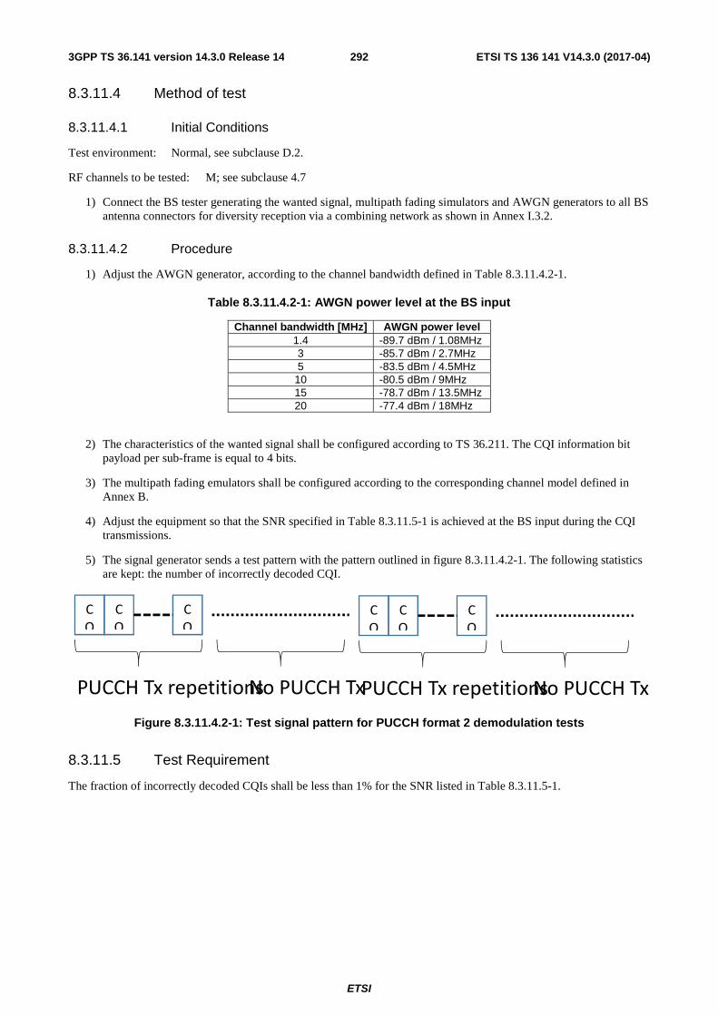
ETSI
ETSI TS 136 141 V14.3.0 (2017-04)2923GPP TS 36.141 version 14.3.0 Release 14
8.3.11.4 Method of test
8.3.11.4.1 Initial Conditions
Test environment: Normal, see subclause D.2.
RF channels to be tested: M; see subclause 4.7
1) Connect the BS tester generating the wanted signal, multipath fading simulators and AWGN generators to all BS antenna connectors for diversity reception via a combining network as shown in Annex I.3.2.
8.3.11.4.2 Procedure
1) Adjust the AWGN generator, according to the channel bandwidth defined in Table 8.3.11.4.2-1.
Table 8.3.11.4.2-1: AWGN power level at the BS input
Channel bandwidth [MHz] AWGN power level 1.4 -89.7 dBm / 1.08MHz 3 -85.7 dBm / 2.7MHz 5 -83.5 dBm / 4.5MHz
10 -80.5 dBm / 9MHz 15 -78.7 dBm / 13.5MHz 20 -77.4 dBm / 18MHz
2) The characteristics of the wanted signal shall be configured according to TS 36.211. The CQI information bit payload per sub-frame is equal to 4 bits.
3) The multipath fading emulators shall be configured according to the corresponding channel model defined in Annex B.
4) Adjust the equipment so that the SNR specified in Table 8.3.11.5-1 is achieved at the BS input during the CQI transmissions.
5) The signal generator sends a test pattern with the pattern outlined in figure 8.3.11.4.2-1. The following statistics are kept: the number of incorrectly decoded CQI.
Figure 8.3.11.4.2-1: Test signal pattern for PUCCH format 2 demodulation tests
8.3.11.5 Test Requirement
The fraction of incorrectly decoded CQIs shall be less than 1% for the SNR listed in Table 8.3.11.5-1.
C
Q
C
Q
C
Q
PUCCH Tx repetitions No PUCCH Tx
C
Q
C
Q
C
Q
PUCCH Tx repetitions No PUCCH Tx

ETSI
ETSI TS 136 141 V14.3.0 (2017-04)2933GPP TS 36.141 version 14.3.0 Release 14
Table 8.3.11.5-1: Required SNR for PUCCH format 2 demodulation tests
Number of TX
antennas
Number of RX
antennas
Cyclic Prefix
Propagation conditions
and correlation
matrix (Annex B)
Repetitions Channel Bandwidth / SNR [dB] 3
MHz 5
MHz 10
MHz 15
MHz 20
MHz
1 2 normal EVA5 Low 4 [3.5-] [-4.4] [-4.5] [-4.3] [-4.1] 8 [-9.2] [-9.7] [-9.4] [-9.5] [-9.4] 32 [-13.1] [-13.5] [-13.2] [-13.4] [-13.3]
Note 1: Frequency Hopping Intervals: 4 (FDD); 10 (TDD) Note 2: Guard period shall be created according to TS36.211, 5.2.5 [12]
NOTE: If the above Test Requirement differs from the Minimum Requirement then the Test Tolerance applied for this test is non-zero. The Test Tolerance for this test and the explanation of how the Minimum Requirement has been relaxed by the Test Tolerance is given in Annex G.
8.3.12 ACK missed detection for PUCCH format 4
8.3.12.1 Definition and applicability
The performance requirement of PUCCH format 4 for ACK missed detection is determined by the two parameters: probability of false detection of the ACK and the probability of detection of ACK. The performance is measured by the required SNR at probability of detection equal to 0.99. The probability of false detection of the ACK shall be 0.01 or less.
The probability of false detection of the ACK is defined as a conditional probability of erroneous detection of the ACK at particular bit position when input is only noise.
The probability of detection of ACK is defined as conditional probability of detection of the ACK when the ACK was sent at particular bit position. Each missed ACK bit is counted as one error.
The test is applicable to all BS. A test for a specific channel bandwidth is only applicable if the BS supports it.
For a BS supporting multiple channel bandwidths only the tests for the lowest and the highest channel bandwidth supported by the BS are applicable.
The number of encoded ACK/NACK bits per sub-frame is defined for two cases as presented below:
- 24AN bits with 1PRB allocated: applicable for FDD and TDD
- 64AN bits with 2PRB allocated: applicable for FDD and TDD
In this test PUCCH is transmitted only on PCell.
ACK/NACK repetitions are disabled for PUCCH transmission. DAI based codebook size determination is disabled. Random codeword selection is assumed.
8.3.12.2 Minimum Requirement
The minimum requirement is in TS 36.104 [2] subclause 8.3.1.1 and 8.3.9.1.
8.3.12.3 Test purpose
The test shall verify the receiver’s ability to detect ACK bits in codeword’s from applicable codebook being randomly selected, under multipath fading propagation conditions for a given SNR.
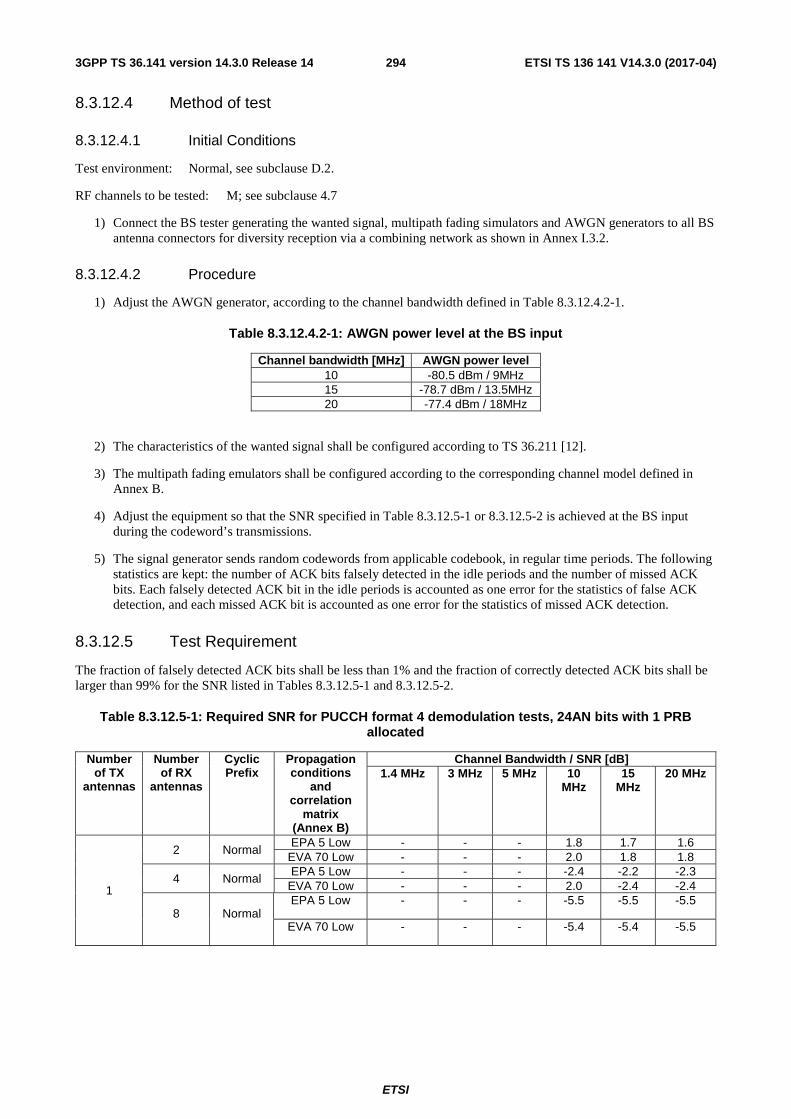
ETSI
ETSI TS 136 141 V14.3.0 (2017-04)2943GPP TS 36.141 version 14.3.0 Release 14
8.3.12.4 Method of test
8.3.12.4.1 Initial Conditions
Test environment: Normal, see subclause D.2.
RF channels to be tested: M; see subclause 4.7
1) Connect the BS tester generating the wanted signal, multipath fading simulators and AWGN generators to all BS antenna connectors for diversity reception via a combining network as shown in Annex I.3.2.
8.3.12.4.2 Procedure
1) Adjust the AWGN generator, according to the channel bandwidth defined in Table 8.3.12.4.2-1.
Table 8.3.12.4.2-1: AWGN power level at the BS input
Channel bandwidth [MHz] AWGN power level 10 -80.5 dBm / 9MHz 15 -78.7 dBm / 13.5MHz 20 -77.4 dBm / 18MHz
2) The characteristics of the wanted signal shall be configured according to TS 36.211 [12].
3) The multipath fading emulators shall be configured according to the corresponding channel model defined in Annex B.
4) Adjust the equipment so that the SNR specified in Table 8.3.12.5-1 or 8.3.12.5-2 is achieved at the BS input during the codeword’s transmissions.
5) The signal generator sends random codewords from applicable codebook, in regular time periods. The following statistics are kept: the number of ACK bits falsely detected in the idle periods and the number of missed ACK bits. Each falsely detected ACK bit in the idle periods is accounted as one error for the statistics of false ACK detection, and each missed ACK bit is accounted as one error for the statistics of missed ACK detection.
8.3.12.5 Test Requirement
The fraction of falsely detected ACK bits shall be less than 1% and the fraction of correctly detected ACK bits shall be larger than 99% for the SNR listed in Tables 8.3.12.5-1 and 8.3.12.5-2.
Table 8.3.12.5-1: Required SNR for PUCCH format 4 demodulation tests, 24AN bits with 1 PRB allocated
Number of TX
antennas
Number of RX
antennas
Cyclic Prefix
Propagation conditions
and correlation
matrix (Annex B)
Channel Bandwidth / SNR [dB] 1.4 MHz 3 MHz 5 MHz 10
MHz 15
MHz 20 MHz
1
2 Normal EPA 5 Low - - - 1.8 1.7 1.6
EVA 70 Low - - - 2.0 1.8 1.8
4 Normal EPA 5 Low - - - -2.4 -2.2 -2.3
EVA 70 Low - - - 2.0 -2.4 -2.4
8 Normal EPA 5 Low - - - -5.5 -5.5 -5.5
EVA 70 Low - - - -5.4 -5.4 -5.5

ETSI
ETSI TS 136 141 V14.3.0 (2017-04)2953GPP TS 36.141 version 14.3.0 Release 14
Table 8.3.12.5-2: Required SNR for PUCCH format 4 demodulation tests, 64AN bits with 2 PRB allocated
Number of TX
antennas
Number of RX
antennas
Cyclic Prefix
Propagation conditions
and correlation
matrix (Annex B)
Channel Bandwidth / SNR [dB] 1.4 MHz 3 MHz 5 MHz 10
MHz 15
MHz 20 MHz
1
2 Normal EPA 5 Low - - - 2.3 2.1 2.1
EVA 70 Low - - - 2.7 2.6 2.5
4 Normal EPA 5 Low - - - -2.4 -2.3 -2.3
EVA 70 Low - - - -1.9 -2.1 -2.1
8 Normal EPA 5 Low - - - -5.7 -5.7 -5.8
EVA 70 Low - - - -5.4 -5.6 -5.6
NOTE: If the above Test Requirement differs from the Minimum Requirement then the Test Tolerance applied for this test is non-zero. The Test Tolerance for this test and the explanation of how the Minimum Requirement has been relaxed by the Test Tolerance is given in Annex G.
8.3.13 ACK missed detection for PUCCH format 5
8.3.13.1 Definition and applicability
The performance requirement of PUCCH format 5 for ACK missed detection is determined by the two parameters: probability of false detection of the ACK and the probability of detection of ACK. The performance is measured by the required SNR at probability of detection equal to 0.99. The probability of false detection of the ACK shall be 0.01 or less.
The probability of false detection of the ACK is defined as a conditional probability of erroneous detection of the ACK at particular bit position when input is only noise.
The probability of detection of ACK is defined as conditional probability of detection of the ACK when the ACK was sent at particular bit position. Each missed ACK bit is counted as one error.
The test is applicable if BS supports PUCCH format 5. A test for a specific channel bandwidth is only applicable if the BS supports it.
For a BS supporting multiple channel bandwidths only the tests for the lowest and the highest channel bandwidth supported by the BS are applicable.
The number of encoded ACK/NACK bits per sub-frame is equal to 24 bits.
ACK/NACK repetitions are disabled for PUCCH transmission. DAI based codebook size determination is disabled. Random codeword selection is assumed.
In this test PUCCH is transmitted only on PCell.
8.3.13.2 Minimum Requirement
The minimum requirement is in TS 36.104 [2] subclause 8.3.1.1 and 8.3.12.1.
8.3.13.3 Test purpose
The test shall verify the receiver’s ability to detect ACK bits in codeword’s from applicable codebook being randomly selected, under multipath fading propagation conditions for a given SNR.

ETSI
ETSI TS 136 141 V14.3.0 (2017-04)2963GPP TS 36.141 version 14.3.0 Release 14
8.3.13.4 Method of test
8.3.13.4.1 Initial Conditions
Test environment: Normal, see subclause D.2.
RF channels to be tested: M; see subclause 4.7
1) Connect the BS tester generating the wanted signal, multipath fading simulators and AWGN generators to all BS antenna connectors for diversity reception via a combining network as shown in Annex I.3.2.
8.3.13.4.2 Procedure
1) Adjust the AWGN generator, according to the channel bandwidth defined in Table 8.3.13.4.2-1.
Table 8.3.5.11.2-1: AWGN power level at the BS input
Channel bandwidth [MHz] AWGN power level 10 -80.5 dBm / 9MHz 15 -78.7 dBm / 13.5MHz 20 -77.4 dBm / 18MHz
2) The characteristics of the wanted signal shall be configured according to TS 36.211 [12].
3) The multipath fading emulators shall be configured according to the corresponding channel model defined in Annex B.
4) Adjust the equipment so that the SNR specified in Table 8.3.13.5-1 is achieved at the BS input during the codeword’s transmissions.
5) The signal generator sends random codewords from applicable codebook, in regular time periods. The following statistics are kept: the number of ACK bits falsely detected in the idle periods and the number of missed ACK bits. Each falsely detected ACK bit in the idle periods is accounted as one error for the statistics of false ACK detection, and each missed ACK bit is accounted as one error for the statistics of missed ACK detection.
8.3.13.5 Test Requirement
The fraction of falsely detected ACK bits shall be less than 1% and the fraction of correctly detected ACK bits shall be larger than 99% for the SNR listed in Tables 8.3.13.5-1.
Table 8.3.13.5-1: Required SNR for PUCCH format 5 demodulation tests
Number of TX
antennas
Number of RX
antennas
Cyclic Prefix
Propagation conditions and
correlation matrix (Annex
B)
Channel Bandwidth / SNR [dB]
1.4MHz 3MHz 5MHz 10 MHz 15MHz 20MHz
1 2 Normal EPA 5 Low - - - 2.2 1.9 1.9 EVA70 Low - - - 2.2 2.1 2.1
4 Normal EPA 5 Low - - - -2.3 -2.2 -2.2 EVA70 Low - - - -1.9 -2.2 -2.1
8 Normal EPA 5 Low - - - -5.4 -5.3 -5.4 EVA70 Low - - - -5.2 -5.3 -5.4
NOTE: If the above Test Requirement differs from the Minimum Requirement then the Test Tolerance applied for this test is non-zero. The Test Tolerance for this test and the explanation of how the Minimum Requirement has been relaxed by the Test Tolerance is given in Annex G.

ETSI
ETSI TS 136 141 V14.3.0 (2017-04)2973GPP TS 36.141 version 14.3.0 Release 14
8.4 Performance requirements for PRACH
8.4.1 PRACH false alarm probability and missed detection
8.4.1.1 Definition and applicability
The performance requirement of PRACH for preamble detection is determined by the two parameters: total probability of false detection of the preamble (Pfa) and the probability of detection of preamble (Pd). The performance is measured by the required SNR at probability of detection, Pd of 99%. Pfa shall be 0.1% or less.
Pfa is defined as a conditional total probability of erroneous detection of the preamble (i.e. erroneous detection from any detector) when input is only noise.
Pd is defined as conditional probability of detection of the preamble when the signal is present. The erroneous detection consists of several error cases – detecting different preamble than the one that was sent, not detecting a preamble at all or correct preamble detection but with the wrong timing estimation. For AWGN, a timing estimation error occurs if the estimation error of the timing of the strongest path is larger than 1.04us. For ETU70, and EPA1 a timing estimation error occurs if the estimation error of the timing of the strongest path is larger than 2.08us. The strongest path for the timing estimation error refers to the strongest path (i.e. average of the delay of all paths having the same highest gain = 310ns for ETU) in the power delay profile.
The test preambles for normal mode are listed in table A.6-1 and the test preambles for high speed mode are listed in A.6-2. The test preambles for supporting Cat-M1 PRACH are listed in table A.6-3.
The normal mode test (Table 8.4.1.5-1) is applicable to all BS. The high speed mode test (Table 8.4.1.5-2) is applicable to high speed BS. The Cat-M1 mode tests (Table 8.4.1.5-3 and Table 8.4.1.5-4) are applicable to the base stations supporting Cat-M1 UEs.
8.4.1.2 Minimum Requirement
The minimum requirement is in TS 36.104 [2] subclause 8.4.1.1 and 8.4.2.1.
8.4.1.3 Test purpose
The test shall verify the receiver’s ability to detect PRACH preamble under multipath fading propagation conditions for a given SNR.
8.4.1.4 Method of test
8.4.1.4.1 Initial Conditions
Test environment: Normal, see subclause D.2.
RF channels to be tested: M; see subclause 4.7
1) Connect the BS tester generating the wanted signal, multipath fading simulators and AWGN generators to all BS antenna connectors for diversity reception via a combining network as shown in Annex I.3.1 or Annex I.3.2 as applicable.
8.4.1.4.2 Procedure
1) Adjust the AWGN generator, according to the channel bandwidth.

ETSI
ETSI TS 136 141 V14.3.0 (2017-04)2983GPP TS 36.141 version 14.3.0 Release 14
Table 8.4.1.4.2-1: AWGN power level at the BS input
Channel bandwidth [MHz] AWGN power level 1.4 -89.7 dBm / 1.08MHz 3 -85.7 dBm / 2.7MHz 5 -83.5 dBm / 4.5MHz
10 -80.5 dBm / 9MHz 15 -78.7 dBm / 13.5MHz 20 -77.4 dBm / 18MHz
2) The characteristics of the wanted signal shall be configured according to the corresponding UL reference measurement channel defined in Annex A.
3) The multipath fading emulators shall be configured according to the corresponding channel model defined in Annex B.
4) Adjust the frequency offset of the test signal according to Table 8.4.1.5-1 or 8.4.1.5-2 or 8.4.1.5-3 or 8.4.1.5-4.
5) Adjust the equipment so that the SNR specified in Table 8.4.1.5-1 or 8.4.1.5-2 or 8.4.1.5-3 or 8.4.1.5-4 is achieved at the BS input during the PRACH preambles.
6) The test signal generator sends a preamble and the receiver tries to detect the preamble. This pattern is repeated as illustrated in figure 8.4.1.4.2-1. The preambles are sent with certain timing offsets as described below. The following statistics are kept: the number of preambles detected in the idle period and the number of missed preambles.
Preamble Preamble
Figure 8.4.1.4.2-1: PRACH preamble test pattern
The timing offset base value is set to 50% of Ncs. This offset is increased within the loop, by adding in each step a value of 0.1us, until the end of the tested range, which is 0.9us. Then the loop is being reset and the timing offset is set again to 50% of Ncs. The timing offset scheme is presented in Figure 8.4.1.4.2-2.
Figure 8.4.1.4.2-2: Timing offset scheme
8.4.1.5 Test Requirement
Pfa shall not exceed 0.1%. Pd shall not be below 99% for the SNRs in Tables 8.4.1.5-1 to 8.4.1.5-4.

ETSI
ETSI TS 136 141 V14.3.0 (2017-04)2993GPP TS 36.141 version 14.3.0 Release 14
Table 8.4.1.5-1: PRACH missed detection test requirements for Normal Mode
Number of TX antennas
Number of RX
antennas
Propagation conditions and
correlation matrix (Annex B)
Frequency offset
SNR [dB] Burst format
0
Burst format
1
Burst format
2
Burst format
3
Burst format
4 1 2 AWGN 0 -13.9 -13.9 -16.1 -16.2 -6.9
ETU 70 Low* 270 Hz -7.4 -7.2 -9.4 -9.5 0.5 4 AWGN 0 -16.6 -16.4 -18.7 -18.5 -9.5
ETU 70 Low* 270 Hz -11.5 -11.1 -13.5 -13.3 -4.5 8 AWGN 0 -19.5 -19.1 -21.2 -21 -11.5
ETU 70 Low* 270 Hz -15.7 -15.3 -17.2 -16.9 -8.0 Note*: Not applicable for Local Area BS and Home BS.
The requirements in Table 8.4.1.5-2 shall not be applied to Local Area BS and Home BS
Table 8.4.1.5-2: PRACH missed detection test requirements for High speed Mode
Number of TX
antennas
Number of RX
antennas
Propagation conditions and
correlation matrix (Annex B)
Frequency offset
SNR [dB] Burst format
0
Burst format
1
Burst format
2
Burst format
3 1 2 AWGN 0 -13.8 -13.9 -16.0 -16.3
ETU 70 Low 270 Hz -6.8 -6.7 -8.7 -8.9 AWGN 625 Hz -12.1 -12.0 -14.1 -14.1 AWGN 1340 Hz -13.1 -13.2 -15.2 -15.4
4 AWGN 0 -16.6 -16.3 -18.6 -18.5 ETU 70 Low 270 Hz -11.2 -10.8 -13.1 -13.1
AWGN 625 Hz -14.6 -14.3 -16.5 -16.5 AWGN 1340 Hz -15.6 -15.2 -17.5 -17.5
8 AWGN 0 -19.0 -18.8 -20.6 -20.7 ETU 70 Low 270 Hz -15.0 -14.5 -16.4 -16.4
AWGN 625 Hz -17.4 -17.1 -19.0 -19.1 AWGN 1340 Hz -18.4 -18.1 -20.2 -20.2
Table 8.4.1.5-3: PRACH missed detection requirements for Cat-M1 Mode (PRACH frequency hopping OFF)
Number of TX
antennas
Number of RX
antennas
Propagation conditions and
correlation matrix (Annex B)
Frequency offset
Number of Repetitions
SNR [dB] Burst format
0
Burst format
1
Burst format
2
Burst format
3 1 2 AWGN 0 4 - - -21.0 -20.8
8 -21.4 -21.0 - - 16 - - -24.8 -24.7 32 -25.3 -25.0 - -
EPA1 Low 270 Hz 4 - - -11.5 -11.1 8 -12.4 -11.7 - - 16 - - -16.6 -16.6 32 -18.4 -18.0 - -
Note 1: Under fading channels, the PRACH detection performance may be significantly different with different PRACH Configuration Indexes. The requirements in this table are defined based on the simulation results with PRACH Configuration Indexes (3, 19, 35, 51) for Format 0, Format 1, Format 2, and Format 3 respectively.
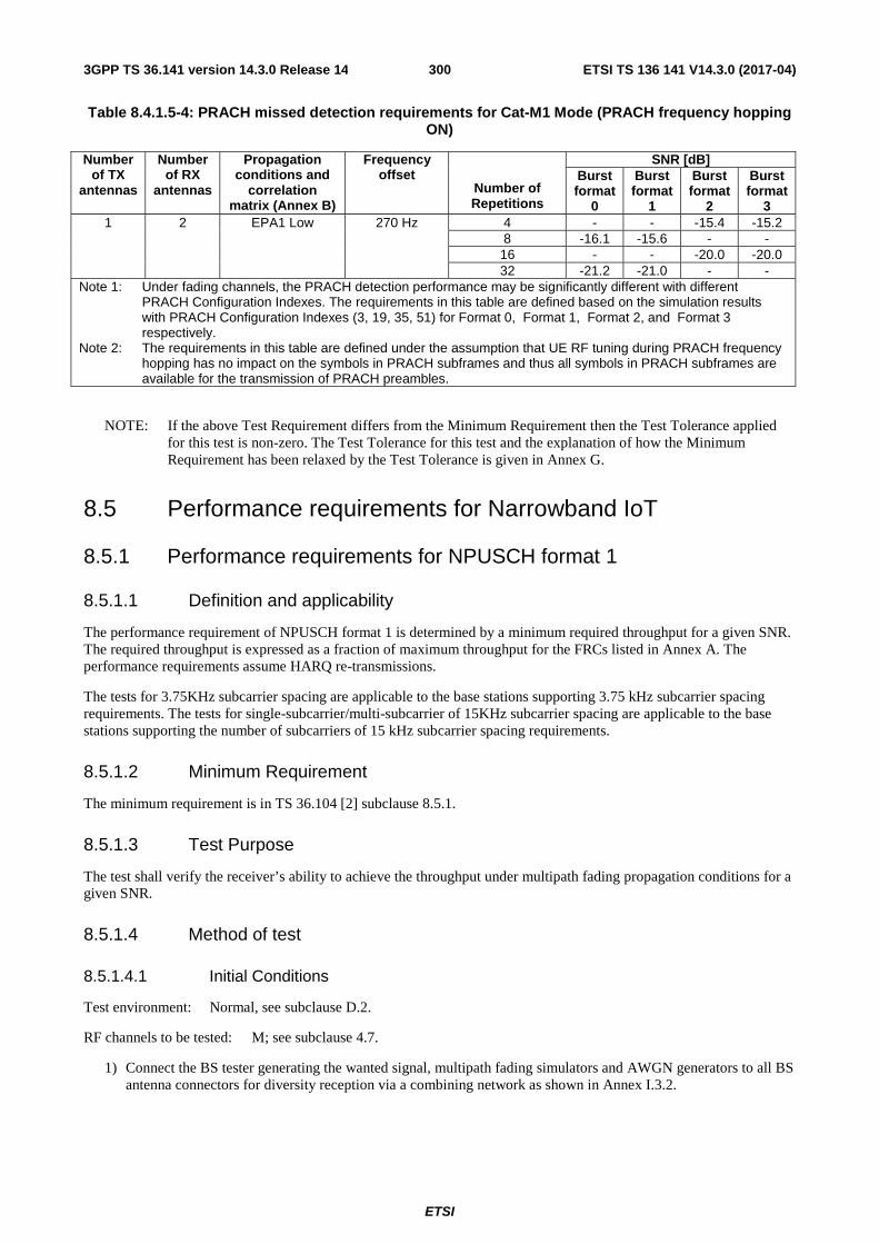
ETSI
ETSI TS 136 141 V14.3.0 (2017-04)3003GPP TS 36.141 version 14.3.0 Release 14
Table 8.4.1.5-4: PRACH missed detection requirements for Cat-M1 Mode (PRACH frequency hopping ON)
Number of TX
antennas
Number of RX
antennas
Propagation conditions and
correlation matrix (Annex B)
Frequency offset
Number of Repetitions
SNR [dB] Burst format
0
Burst format
1
Burst format
2
Burst format
3 1 2 EPA1 Low 270 Hz 4 - - -15.4 -15.2
8 -16.1 -15.6 - - 16 - - -20.0 -20.0 32 -21.2 -21.0 - -
Note 1: Under fading channels, the PRACH detection performance may be significantly different with different PRACH Configuration Indexes. The requirements in this table are defined based on the simulation results with PRACH Configuration Indexes (3, 19, 35, 51) for Format 0, Format 1, Format 2, and Format 3 respectively.
Note 2: The requirements in this table are defined under the assumption that UE RF tuning during PRACH frequency hopping has no impact on the symbols in PRACH subframes and thus all symbols in PRACH subframes are available for the transmission of PRACH preambles.
NOTE: If the above Test Requirement differs from the Minimum Requirement then the Test Tolerance applied for this test is non-zero. The Test Tolerance for this test and the explanation of how the Minimum Requirement has been relaxed by the Test Tolerance is given in Annex G.
8.5 Performance requirements for Narrowband IoT
8.5.1 Performance requirements for NPUSCH format 1
8.5.1.1 Definition and applicability
The performance requirement of NPUSCH format 1 is determined by a minimum required throughput for a given SNR. The required throughput is expressed as a fraction of maximum throughput for the FRCs listed in Annex A. The performance requirements assume HARQ re-transmissions.
The tests for 3.75KHz subcarrier spacing are applicable to the base stations supporting 3.75 kHz subcarrier spacing requirements. The tests for single-subcarrier/multi-subcarrier of 15KHz subcarrier spacing are applicable to the base stations supporting the number of subcarriers of 15 kHz subcarrier spacing requirements.
8.5.1.2 Minimum Requirement
The minimum requirement is in TS 36.104 [2] subclause 8.5.1.
8.5.1.3 Test Purpose
The test shall verify the receiver’s ability to achieve the throughput under multipath fading propagation conditions for a given SNR.
8.5.1.4 Method of test
8.5.1.4.1 Initial Conditions
Test environment: Normal, see subclause D.2.
RF channels to be tested: M; see subclause 4.7.
1) Connect the BS tester generating the wanted signal, multipath fading simulators and AWGN generators to all BS antenna connectors for diversity reception via a combining network as shown in Annex I.3.2.

ETSI
ETSI TS 136 141 V14.3.0 (2017-04)3013GPP TS 36.141 version 14.3.0 Release 14
8.5.1.4.2 Procedure
1) Adjust the AWGN generator, according to the channel bandwidth, defined in Table 8.5.1.4.2-1.
Table 8.5.1.4.2-1: AWGN power level at the BS input
Channel bandwidth [KHz] AWGN power level 200 -100.5dBm /180KHz
2) The characteristics of the wanted signal shall be configured according to the corresponding UL reference measurement channel defined in annex A and the test parameters in Table 8.5.1.4.2-2.
Table 8.5.1.4.2-2: Test parameters for testing NPUSCH format 2
Parameter unit Value Maximum number of HARQ
transmissions
4
RV sequences RV0, RV2
3) The multipath fading emulators shall be configured according to the corresponding channel model defined in annex B.
4) Adjust the equipment so that required SNR specified in tables 8.5.1.5-1 to 8.5.1.5-3 is achieved at the BS input.
5) For each of the reference channels in Table 8.5.1.5-1 to 8.5.1.5-3 applicable for the base station, measure the throughput, according to annex E.
8.5.1.5 Test Requirement
The throughput measured according to subclause 8.5.1.4.2 shall not be below the limits for the SNR levels specified in Table 8.5.1.5-1 for 3.75KHz subcarrier spacing tests, not be below the limits for the SNR levels specified in Table 8.5.1.5-2 for 15KHz subcarrier spacing with single subcarrier tests and not be below the limits for the SNR levels specified in Table 8.5.1.5-3 for 15KHz subcarrier spacing with the supported number of subcarrier tests.
Table 8.5.1.5-1 Required SNR for NPUSCH format 1 test, 200KHz Channel Bandwidth, 3.75KHz subcarrier spacing, 1Tx
Number of TX
antennas
Number of RX
antennas
Subcarrier spacing
Number of allocated
subcarriers
Propagation conditions
and correlation
matrix (Annex B)
FRC (Annex
A)
Repetition number
Fraction of maximum
throughput
SNR [dB]
1 2 3.75KHz 1 ETU 1Hz Low A16-1
1 70% -1.3 16 70% -8.6
64 70% -11.6
Table 8.5.1.5-2 Required SNR for NPUSCH format 1 test, 200KHz Channel Bandwidth, 15KHz subcarrier spacing, single subcarrier, 1Tx
Number of TX
antennas
Number of RX
antennas
Subcarrier spacing
Number of allocated
subcarriers
Propagation conditions
and correlation
matrix (Annex B)
FRC (Annex
A)
Repetition number
Fraction of maximum
throughput
SNR [dB]
1 2 15KHz 1 ETU 1Hz
Low A16-2
1 70% -1.5 16 70% -8.2
64 70% -11.9

ETSI
ETSI TS 136 141 V14.3.0 (2017-04)3023GPP TS 36.141 version 14.3.0 Release 14
Table 8.5.1.5-3 Required SNR for NPUSCH format 1 test, 200KHz Channel Bandwidth, 15KHz subcarrier spacing, multiple subcarriers, 1Tx
Number of TX
antennas
Number of RX
antennas
Subcarrier spacing
Number of allocated
subcarriers
Propagation conditions
and correlation
matrix (Annex B)
FRC (Annex
A)
Repetition number
Fraction of maximum
throughput
SNR [dB]
1 2 15KHz
3 ETU 1Hz Low
A16-3
2 70% -2.4 16 70% -7.5
64 70% -10.8
6 ETU 1Hz Low A16-4
2 70% 0.1 16 70% -6.2 64 70% -9.9
12 ETU 1Hz Low A16-5
2 70% 1.3 16 70% -5.8 64 70% -9.5
NOTE: If the above Test Requirement differs from the Minimum Requirement then the Test Tolerance applied for this test is non-zero. The Test Tolerance for this test and the explanation of how the Minimum Requirement has been relaxed by the Test Tolerance is given in Annex G.
8.5.2 ACK missed detection for NPUSCH format 2
8.5.2.1 Definition and applicability
The performance requirement of NPUSCH format 2 for ACK missed detection is determined by the two parameters: probability of false detection of the ACK and the probability of detection of ACK. The performance is measured by the required SNR at probability of detection equal to 0.99. The probability of false detection of the ACK shall be 0.01 or less.
The probability of false detection of the ACK is defined as a conditional probability of erroneous detection of the ACK when input is only noise.
The probability of detection of ACK is defined as conditional probability of detection of the ACK when the ACK was sent per NPUSCH format 2 transmission when the signal is present.
The tests for 3.75KHz subcarrier spacing are applicable to the base stations supporting 3.75 KHz subcarrier spacing requirements. The tests for 15KHz subcarrier spacing are applicable to the base stations supporting 15KHz subcarrier spacing requirements.
8.5.2.2 Minimum Requirement
The minimum requirement is in TS 36.104 [2] subclause 8.5.2.1 and 8.5.2.2.
8.5.2.3 Test purpose
The test shall verify the receiver’s ability to detect ACK under multipath fading propagation conditions for a given SNR.
8.5.2.4 Method of test
8.5.2.4.1 Initial Conditions
Test environment: Normal, see subclause D.2.
RF channels to be tested: M; see subclause 4.7

ETSI
ETSI TS 136 141 V14.3.0 (2017-04)3033GPP TS 36.141 version 14.3.0 Release 14
1) Connect the BS tester generating the wanted signal, multipath fading simulators and AWGN generators to all BS antenna connectors for diversity reception via a combining network as shown in Annex I.3.2.
8.5.2.4.2 Procedure
1) Adjust the AWGN generator, according to the channel bandwidth defined in Table 8.5.2.4.2-1.
Table 8.5.2.4.2-1: AWGN power level at the BS input
Channel bandwidth [KHz] AWGN power level 200 -100.5dBm /180KHz
2) The characteristics of the wanted signal shall be configured according to TS 36.211 [12].
3) The multipath fading emulators shall be configured according to the corresponding channel model defined in Annex B.
4) Adjust the equipment so that the SNR specified in tables 8.5.2.5-1 to 8.5.2.5-2 is achieved at the BS input during the ACK transmissions.
5) The signal generator sends a test pattern with the pattern outlined in figure 8.5.2.4.2-1. The following statistics are kept: the number of ACKs falsely detected in the idle periods and the number of missed ACKs. Each falsely detected ACK transmission in the idle periods is accounted as one error for the statistics of false ACK detection, and each missed ACK transmission per NPUSCH format 2 transmisson is accounted as one error for the statistics of missed ACK detection.
Figure 8.5.2.4.2-1: Test signal pattern for NPUSCH format 2 demodulation tests
8.5.2.5 Test Requirement
The fraction of falsely detected ACKs shall be less than 1% and the fraction of correctly detected ACKs shall be larger than 99% for the SNR listed in Table 8.5.2.5-1 and Table 8.5.2.5-2.
Table 8.5.2.5-1 Required SNR for NPUSCH format 2 test, 200KHz Channel Bandwidth, 3.75KHz subcarrier spacing, 1Tx
Number of TX
antennas
Number of RX
antennas
Propagation conditions
and correlation
matrix (Annex B)
Number of allocated
subcarriers
Subcarrier spacing
Repetition number
SNR [dB]
1 2 EPA 5 Low 1 3.75KHz 1 7.6 16 -4.7 64 -10.3
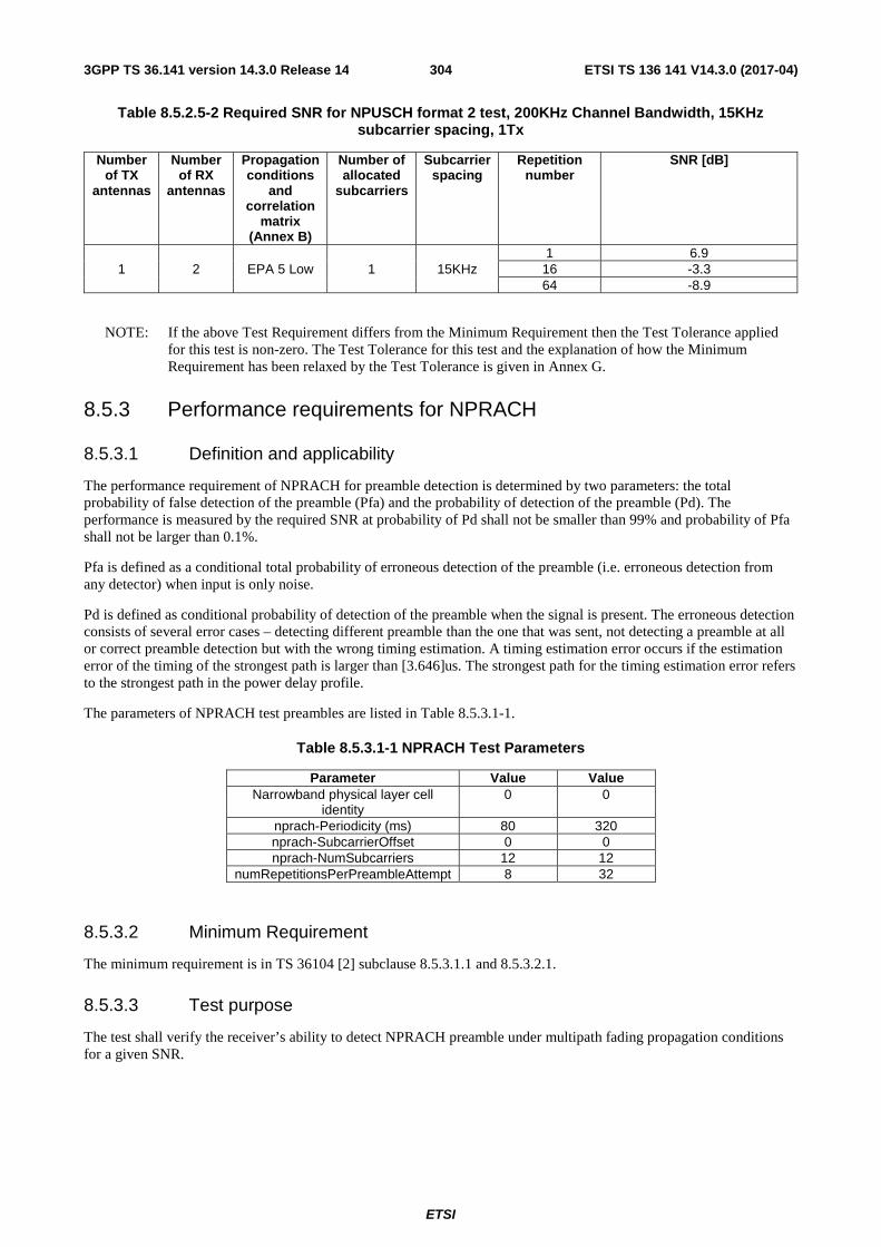
ETSI
ETSI TS 136 141 V14.3.0 (2017-04)3043GPP TS 36.141 version 14.3.0 Release 14
Table 8.5.2.5-2 Required SNR for NPUSCH format 2 test, 200KHz Channel Bandwidth, 15KHz subcarrier spacing, 1Tx
Number of TX
antennas
Number of RX
antennas
Propagation conditions
and correlation
matrix (Annex B)
Number of allocated
subcarriers
Subcarrier spacing
Repetition number
SNR [dB]
1 2 EPA 5 Low 1 15KHz 1 6.9
16 -3.3 64 -8.9
NOTE: If the above Test Requirement differs from the Minimum Requirement then the Test Tolerance applied for this test is non-zero. The Test Tolerance for this test and the explanation of how the Minimum Requirement has been relaxed by the Test Tolerance is given in Annex G.
8.5.3 Performance requirements for NPRACH
8.5.3.1 Definition and applicability
The performance requirement of NPRACH for preamble detection is determined by two parameters: the total probability of false detection of the preamble (Pfa) and the probability of detection of the preamble (Pd). The performance is measured by the required SNR at probability of Pd shall not be smaller than 99% and probability of Pfa shall not be larger than 0.1%.
Pfa is defined as a conditional total probability of erroneous detection of the preamble (i.e. erroneous detection from any detector) when input is only noise.
Pd is defined as conditional probability of detection of the preamble when the signal is present. The erroneous detection consists of several error cases – detecting different preamble than the one that was sent, not detecting a preamble at all or correct preamble detection but with the wrong timing estimation. A timing estimation error occurs if the estimation error of the timing of the strongest path is larger than [3.646]us. The strongest path for the timing estimation error refers to the strongest path in the power delay profile.
The parameters of NPRACH test preambles are listed in Table 8.5.3.1-1.
Table 8.5.3.1-1 NPRACH Test Parameters
Parameter Value Value Narrowband physical layer cell
identity 0 0
nprach-Periodicity (ms) 80 320 nprach-SubcarrierOffset 0 0 nprach-NumSubcarriers 12 12
numRepetitionsPerPreambleAttempt 8 32
8.5.3.2 Minimum Requirement
The minimum requirement is in TS 36104 [2] subclause 8.5.3.1.1 and 8.5.3.2.1.
8.5.3.3 Test purpose
The test shall verify the receiver’s ability to detect NPRACH preamble under multipath fading propagation conditions for a given SNR.

ETSI
ETSI TS 136 141 V14.3.0 (2017-04)3053GPP TS 36.141 version 14.3.0 Release 14
8.5.3.4 Method of test
8.5.3.4.1 Initial Conditions
Test environment: Normal, see subclause D.2.
RF channels to be tested: M; see subclause 4.7.
1) Connect the BS tester generating the wanted signal, multipath fading simulators and AWGN generators to all BS antenna connectors for diversity reception via a combining network as shown in Annex I.3.2.
8.5.3.4.2 Procedure
1) Adjust the AWGN generator, according to the channel bandwidth.
Table 8.5.3.4.2-1: AWGN power level at the BS input
Channel bandwidth [KHz] AWGN power level 200 -100.5dBm /180KHz
2) The characteristics of the wanted signal shall be configured according to the corresponding UL reference measurement channel defined in Annex A.
3) The multipath fading emulators shall be configured according to the corresponding channel model defined in Annex B.
4) Adjust the frequency offset of the test signal according to Table 8.5.3.5-1.
5) Adjust the equipment so that the SNR specified in Table 8.5.3.5-1 is achieved at the BS input during the NPRACH preambles.
6) The test signal generator sends a preamble with repetitions and the receiver tries to detect the preamble. This pattern is repeated as illustrated in figure 8.5.3.4.2-1. The preambles are sent with a fixed timing offset of 0.5��� during the test, where ��� is NPRACH cyclic prefix of length as defined in TS36.211 [12]. The following statistics are kept: the number of preambles detected in the idle period and the number of missed preambles.
Preamble Preamble
Figure 8.5.3.4.2-1: NPRACH preamble test pattern
8.5.3.5 Test Requirement
Pfa shall not exceed 0.1% and Pmd shall not exceed 1% for the SNRs in Table 8.5.3.5-1.
Table 8.5.3.5-1: NPRACH missed detection test requirements
Number of TX
antennas
Number of RX
antennas
Repetition number
Propagation conditions
and correlation
matrix (Annex B)
Frequency offset
SNR[dB] Preamble format 0
Preamble format 1
1 2 8 AWGN 0 -1.8 -1.8 EPA1 Low 200 Hz 6.7 6.7
32 AWGN 0 -6.5 -6.5 EPA1 Low 200 Hz 1.1 1.1

ETSI
ETSI TS 136 141 V14.3.0 (2017-04)3063GPP TS 36.141 version 14.3.0 Release 14
9 Channel access procedures
9.1 Downlink channel access procedure
9.1.1 Definition and applicability
Channel access procedure for downlink operation in Band 46 for PDSCH transmission is described in TS 36.213, Clause 15.
9.1.2 Minimum requirement
The minimum requirement is in TS 36.104 [2] subclause 9.1.
9.1.3 Test purpose
The test purpose is to verify the accuracy of the energy detection threshold, maximum channel occupancy time (MCOT) and minimum idle time under normal conditions for all band 46 transmitters in the BS.
9.1.4 Method of test
9.1.4.1 Initial conditions
Test environment: normal; see Annex D.2.
RF channels to be tested for single carrier: B, M and T; see subclause 4.7.
Connect the signal analyzer to the base station antenna connector as shown in Annex I..
9.1.4.2 Procedure
MCOT and minimum idle time
1) Set the base station to transmit a signal according to E-TM 1.1 at manufacturer’s declared rated output power with 20 MHz channel bandwidth. Channel Access Priority Class 3 parameters are selected to be tested based on Table 15.1.1-1 in TS 36.213.
2) Measure the transmitter ON period during the continuous transmission (after the first channel access).
3) Measure the transmitter OFF period between two consecutive transmitter ON periods.
4) Verify minimum idle time as follows:
The transmitter OFF period between two consecutive transmitter ON periods shall not be less than 25 µs.
5) Verify maximum channel occupancy time (MCOT) as follows:
a) The duration of each transmitter ON period continuous transmission shall not exceed the maximum channel occupancy time (MCOT) requirement specified in clause 9.1.5.
Energy detection accuracy
6) Generate the interfering signal of AWGN with 20 MHz channel bandwidth at the same centre frequency as the tested channel. The interfering signal shall be at a level of (-72dBm+ 4dB)/20MHz. The base station shall stop transmission on the current operating channel and will not resume normal transmissions as long as the interference signal is present.
7) The step 6) is repeated multiple times considering the following sub-steps:
- Interferer ON: if the interfering signal is present, the interfering signal should be present for 10ms.

ETSI
ETSI TS 136 141 V14.3.0 (2017-04)3073GPP TS 36.141 version 14.3.0 Release 14
- Interferer OFF: if the interfering signal is removed, the interfering signal should be absent for 10ms.
Note: the total number of interferer ON duration is assumed to be N and the total number of interferer OFF duration is assumed to be M. The value N, M and the sequence of interferer ON/OFF pattern shall be generated randomly for the test.
8) In the test, a counter is maintained with initial value set to 0 when the test starts.
9) For every 10ms Interferer ON period, the counter is increased by 1 if there is either an ON/OFF transition or no transmission by the DUT. To pass the test, the counter shall not be less than N*0.9.
9.1.5 Test Requirements
In normal conditions, the measurement result shall meet channel access related test requirements for PDSCH as listed in Table 9.1.5-1.
Table 9.1.5-1: Channel access test requirements for PDSCH
Parameter Unit Value LBT measurement bandwidth MHz 20 Maximum energy detection
threshold dBm/20MHz -72 + 4dB
Maximum channel occupancy time ms 8
The Base Station shall be able to assess whether the medium is busy or idle with at least 90% probability, using a channel access procedure with the parameters in Table 9.1.5-1.

ETSI
ETSI TS 136 141 V14.3.0 (2017-04)3083GPP TS 36.141 version 14.3.0 Release 14
Annex A (normative): Reference Measurement channels
A.0 General The parameters for the reference measurement channels are specified in clause A.1 for E-UTRA reference sensitivity and in-channel selectivity and in clause A.2 for dynamic range.
A schematic overview of the encoding process for the E-UTRA reference measurement channels is provided in Figure A0-1.
E-UTRA receiver requirements in the present document are defined with a throughput stated relative to the Maximum throughput of the FRC. The Maximum throughput for an FRC equals the Payload size * the Number of uplink subframes per second. For FDD, 1000 uplink sub-frames per second are used.
The parameters for the reference measurement channels are specified in clause A.14 for NB-IoT reference sensitivity and in-channel selectivity and in clause A.15 for dynamic range.
A schematic overview of the encoding process for the NB-IoT reference measurement channels is provided in Figure A0-2.
NB-IoT receiver requirements in the present document are defined with a throughput stated relative to the Maximum throughput of the FRC. The Maximum throughput for an FRC equals the Payload size/ (Number of Resource Unit * time to send one Resource Unit).

ETSI
ETSI TS 136 141 V14.3.0 (2017-04)3093GPP TS 36.141 version 14.3.0 Release 14
Payload
Code block
Transmitted bits in a single subframe
Code block
Coded block Trellis termination (12 bits)
Rate matched block
Rate R turbo code
Code blocks
Subblock interleaving and Rate matching
Code block
CRC
Other code blocks processed in the same way
CRC CRC CRC
Figure A0-1: Schematic overview of the encoding process
Payload
Code block
Resource Unit
Coded block Trellis termination (12 bits)
Rate matched block
Rate R turbo code
Subblock interleaving and Rate matching
CRC
CRC
Resource Unit 1 sub-carrier
Figure A0-2. Schematic overview of the encoding process for NB-IoT

ETSI
ETSI TS 136 141 V14.3.0 (2017-04)3103GPP TS 36.141 version 14.3.0 Release 14
A.1 Fixed Reference Channels for reference sensitivity and in--channel selectivity (QPSK, R=1/3)
The parameters for the reference measurement channels are specified in Table A.1-1 for reference sensitivity and in-channel selectivity
Table A.1-1: FRC parameters for reference sensitivity and in-channel selectivity
Reference channel A1-1 A1-2 A1-3 A1-4 A1-5 A1-6 A1-7 Allocated resource blocks 6 15 25 3 9 12 24 DFT-OFDM Symbols per subframe 12 12 12 12 12 12 12 Modulation QPSK QPSK QPSK QPSK QPSK QPSK QPSK Code rate 1/3 1/3 1/3 1/3 1/3 1/3 1/3 Payload size (bits) 600 1544 2216 256 936 1224 2088 Transport block CRC (bits) 24 24 24 24 24 24 24 Code block CRC size (bits) 0 0 0 0 0 0 0 Number of code blocks - C 1 1 1 1 1 1 1 Coded block size including 12bits trellis termination (bits)
1884 4716 6732 852 2892 3756 6348
Total number of bits per sub-frame 1728 4320 7200 864 2592 3456 6912 Total symbols per sub-frame 864 2160 3600 432 1296 1728 3456
A.2 Fixed Reference Channels for dynamic range (16QAM, R=2/3)
The parameters for the reference measurement channels are specified in Table A.2-1 for dynamic range.
Table A.2-1: FRC parameters for dynamic range
Reference channel A2-1 A2-2 A2-3 Allocated resource blocks 6 15 25 DFT-OFDM Symbols per subframe 12 12 12 Modulation 16QAM 16QAM 16QAM Code rate 2/3 2/3 2/3 Payload size (bits) 2344 5992 9912 Transport block CRC (bits) 24 24 24 Code block CRC size (bits) 0 0 24 Number of code blocks – C 1 1 2 Coded block size including 12bits trellis termination (bits)
7116 18060 14988
Total number of bits per sub-frame 3456 8640 14400 Total symbols per sub-frame 864 2160 3600
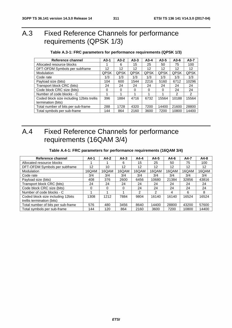
ETSI
ETSI TS 136 141 V14.3.0 (2017-04)3113GPP TS 36.141 version 14.3.0 Release 14
A.3 Fixed Reference Channels for performance requirements (QPSK 1/3)
Table A.3-1: FRC parameters for performance requirements (QPSK 1/3)
Reference channel A3-1 A3-2 A3-3 A3-4 A3-5 A3-6 A3-7 Allocated resource blocks 1 6 15 25 50 75 100 DFT-OFDM Symbols per subframe 12 12 12 12 12 12 12 Modulation QPSK QPSK QPSK QPSK QPSK QPSK QPSK Code rate 1/3 1/3 1/3 1/3 1/3 1/3 1/3 Payload size (bits) 104 600 1544 2216 5160 6712 10296 Transport block CRC (bits) 24 24 24 24 24 24 24 Code block CRC size (bits) 0 0 0 0 0 24 24 Number of code blocks - C 1 1 1 1 1 2 2 Coded block size including 12bits trellis termination (bits)
396 1884 4716 6732 15564 10188 15564
Total number of bits per sub-frame 288 1728 4320 7200 14400 21600 28800 Total symbols per sub-frame 144 864 2160 3600 7200 10800 14400
A.4 Fixed Reference Channels for performance requirements (16QAM 3/4)
Table A.4-1: FRC parameters for performance requirements (16QAM 3/4)
Reference channel A4-1 A4-2 A4-3 A4-4 A4-5 A4-6 A4-7 A4-8 Allocated resource blocks 1 1 6 15 25 50 75 100 DFT-OFDM Symbols per subframe 12 10 12 12 12 12 12 12 Modulation 16QAM 16QAM 16QAM 16QAM 16QAM 16QAM 16QAM 16QAM Code rate 3/4 3/4 3/4 3/4 3/4 3/4 3/4 3/4 Payload size (bits) 408 376 2600 6456 10680 21384 32856 43816 Transport block CRC (bits) 24 24 24 24 24 24 24 24 Code block CRC size (bits) 0 0 0 24 24 24 24 24 Number of code blocks - C 1 1 1 2 2 4 6 8 Coded block size including 12bits trellis termination (bits)
1308 1212 7884 9804 16140 16140 16524 16524
Total number of bits per sub-frame 576 480 3456 8640 14400 28800 43200 57600 Total symbols per sub-frame 144 120 864 2160 3600 7200 10800 14400
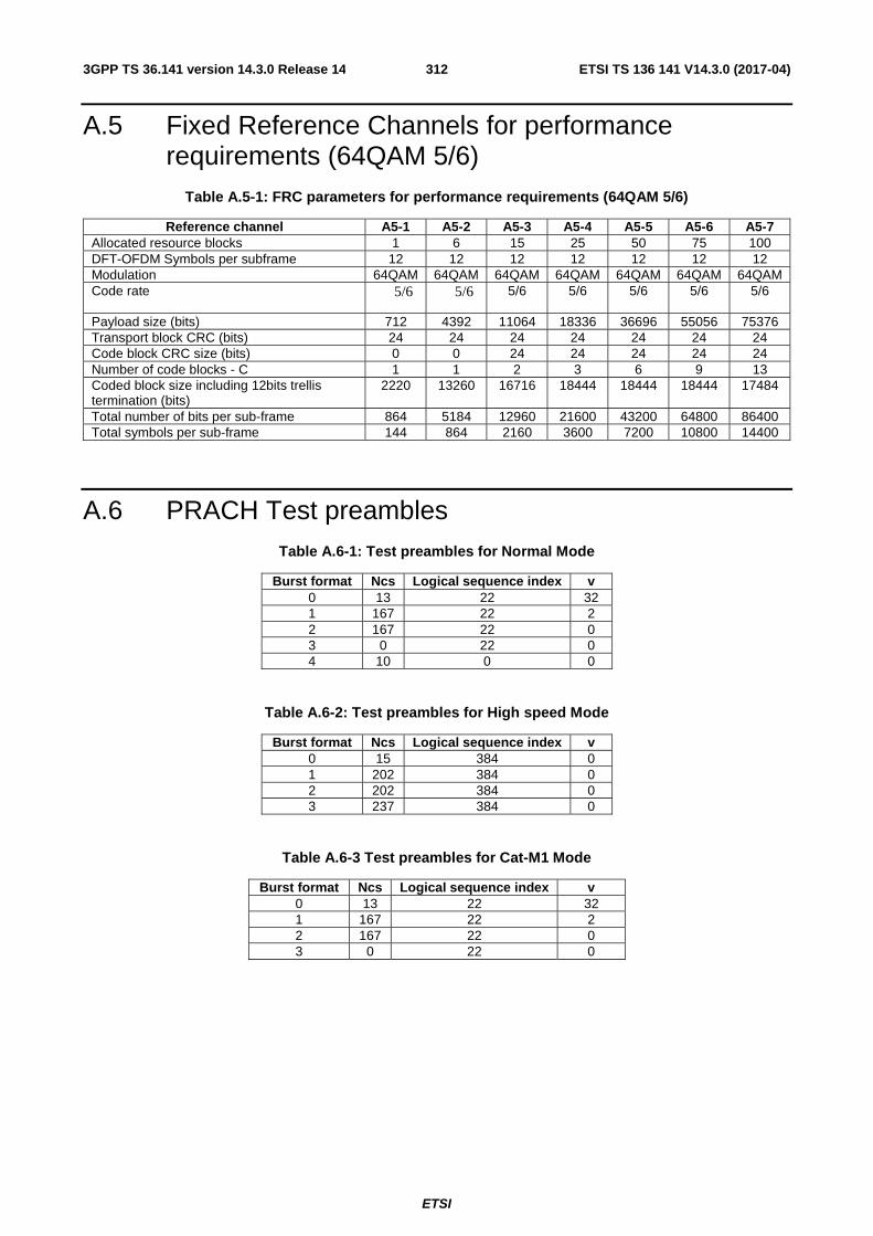
ETSI
ETSI TS 136 141 V14.3.0 (2017-04)3123GPP TS 36.141 version 14.3.0 Release 14
A.5 Fixed Reference Channels for performance requirements (64QAM 5/6)
Table A.5-1: FRC parameters for performance requirements (64QAM 5/6)
Reference channel A5-1 A5-2 A5-3 A5-4 A5-5 A5-6 A5-7 Allocated resource blocks 1 6 15 25 50 75 100 DFT-OFDM Symbols per subframe 12 12 12 12 12 12 12 Modulation 64QAM 64QAM 64QAM 64QAM 64QAM 64QAM 64QAM Code rate 5/6 5/6 5/6 5/6 5/6 5/6 5/6
Payload size (bits) 712 4392 11064 18336 36696 55056 75376 Transport block CRC (bits) 24 24 24 24 24 24 24 Code block CRC size (bits) 0 0 24 24 24 24 24 Number of code blocks - C 1 1 2 3 6 9 13 Coded block size including 12bits trellis termination (bits)
2220 13260 16716 18444 18444 18444 17484
Total number of bits per sub-frame 864 5184 12960 21600 43200 64800 86400 Total symbols per sub-frame 144 864 2160 3600 7200 10800 14400
A.6 PRACH Test preambles Table A.6-1: Test preambles for Normal Mode
Burst format Ncs Logical sequence index v 0 13 22 32 1 167 22 2 2 167 22 0 3 0 22 0 4 10 0 0
Table A.6-2: Test preambles for High speed Mode
Burst format Ncs Logical sequence index v 0 15 384 0 1 202 384 0 2 202 384 0 3 237 384 0
Table A.6-3 Test preambles for Cat-M1 Mode
Burst format Ncs Logical sequence index v 0 13 22 32 1 167 22 2 2 167 22 0 3 0 22 0

ETSI
ETSI TS 136 141 V14.3.0 (2017-04)3133GPP TS 36.141 version 14.3.0 Release 14
A.7 Fixed Reference Channels for UL timing adjustment (Scenario 1)
Table A.7-1: FRC parameters for UL timing adjustment (Scenario 1)
Reference channel A7-1 A7-2 A7-3 A7-4 A7-5 A7-6 Allocated resource blocks 3 6 12 25 25 25 DFT-OFDM Symbols per subframe 12 12 12 12 12 12 Modulation 16QAM 16QAM 16QAM 16QAM 16QAM 16QAM Code rate 3/4 3/4 3/4 3/4 3/4 3/4 Payload size (bits) 1288 2600 5160 10680 10680 10680 Transport block CRC (bits) 24 24 24 24 24 24 Code block CRC size (bits) 0 0 0 24 24 24 Number of code blocks - C 1 1 1 2 2 2 Coded block size including 12bits trellis termination (bits)
3948 7884 15564 16140 16140 16140
Total number of bits per sub-frame 1728 3456 6912 14400 14400 14400 Total symbols per sub-frame 432 864 1728 3600 3600 3600 SRS bandwidth configuration (See TS 36.211, 5.5.3) (Note 1)
7 5 3 2 5 2
SRS-Bandwidth b (See TS 36.211, 5.5.3) (Note 1, 2) 0 0 0 0 0 1 Note 1. The transmission of SRS is optional Note 2. PUSCH resource blocks shall be included in SRS resource blocks
A.8 Fixed Reference Channels for UL timing adjustment (Scenario 2)
Table A.8-1: FRC parameters for UL timing adjustment (Scenario 2)
Reference channel A8-1 A8-2 A8-3 A8-4 A8-5 A8-6 Allocated resource blocks 3 6 12 25 25 25 DFT-OFDM Symbols per subframe 12 12 12 12 12 12 Modulation QPSK QPSK QPSK QPSK QPSK QPSK Code rate 1/3 1/3 1/3 1/3 1/3 1/3 Payload size (bits) 256 600 1224 2216 2216 2216 Transport block CRC (bits) 24 24 24 24 24 24 Code block CRC size (bits) 0 0 0 0 0 0 Number of code blocks - C 1 1 1 1 1 1 Coded block size including 12bits trellis termination (bits) 852 1884 3756 6732 6732 6732 Total number of bits per sub-frame 864 1728 3456 7200 7200 7200 Total symbols per sub-frame 432 864 1728 3600 3600 3600 SRS bandwidth configuration (See TS 36.211, 5.5.3) (Note 1) 7 5 3 2 5 2 SRS-Bandwidth b (See TS 36.211, 5.5.3) (Note 1, 2) 0 0 0 0 0 1 Note 1. The transmission of SRS is optional Note 2. PUSCH resource blocks shall be included in SRS resource blocks

ETSI
ETSI TS 136 141 V14.3.0 (2017-04)3143GPP TS 36.141 version 14.3.0 Release 14
A.9 Multi user PUCCH test Table A.9-1: Test parameters for multi user PUCCH case
Resource index for PUCCH formats 1/1a/1b
(1)PUCCHn
Relative power [dB]
Relative timing [ns]
Tested signal 2 - -
Interferer 1 1 0
0 Interferer 2 7 -3
Interferer 3 14 3
NOTE1: The following parameters shall be used 150cellID =N , 0(1)
cs =N and 2PUCCHshift =Δ .
NOTE2: All above listed signals are transmitted on the same PUCCH resource block, with different PUCCH resource indices as presented above.
A.10 PUCCH transmission on two antenna ports test Table A.10-1: Test parameters for PUCCH transmission on two antenna ports case
PUCCH format Resource indices for two antenna ports
Format 1a 0(1, )PUCCH 1p pn = =
,1(1, )
PUCCH 2p pn = =
Format 2 0(2, )PUCCH 1p pn = =
,1(2, )
PUCCH 2p pn = =
NOTE1: The following parameters shall be used 150cellID =N , 0(1)
cs =N . For PUCCH format 1a, 2PUCCH
shift =Δ is
assumed. NOTE2: The signals transmitted on two antenna ports are in the same PUCCH resource block with different
resource indices as presented above.
A.11 Fixed Reference Channel for PUSCH with TTI bundling and enhanced HARQ pattern
Table A.11-1: FRC parameters for PUSCH with TTI bundling and enhanced HARQ pattern
Reference channel A11-1 Allocated resource blocks 3 DFT-OFDM Symbols per subframe 12 Modulation QPSK Code rate 11/27* Payload size (bits) 328 Transport block CRC (bits) 24 Code block CRC size (bits) 0 Number of code blocks - C 1 Coded block size including 12bits trellis termination (bits) 1068 Total number of bits per sub-frame 864 Total symbols per sub-frame 432 Note *: code rate per TTI

ETSI
ETSI TS 136 141 V14.3.0 (2017-04)3153GPP TS 36.141 version 14.3.0 Release 14
A.12 Fixed Reference Channels for performance requirements (QPSK 0.36)
Table A.12-1 FRC parameters for performance requirements (QPSK 0.36)
Reference channel A12-1 A12-2 A12-3 A12-4 A12-5 A12-6 Allocated resource blocks 6 15 25 50 75 100 DFT-OFDM Symbols per subframe 12 12 12 12 12 12 Modulation QPSK QPSK QPSK QPSK QPSK QPSK Code rate 0.36 0.36 0.36 0.36 0.36 0.36 MCS index 6 6 6 6 6 6 Payload size (bits) 600 1544 2600 5160 7736 10296 Transport block CRC (bits) 24 24 24 24 24 24 Code block CRC size (bits) 0 0 0 0 24 24 Number of code blocks - C 1 1 1 1 2 2 Coded block size including 12bits trellis termination (bits)
1884 4716 7884 15564 11724 15564
Total number of bits per sub-frame 1728 4320 7200 14400 21600 28800
Total symbols per sub-frame 864 2160 3600 7200 10800 14400
NOTE 1: FRC A12-1, A12-2, A12-4, A12-6 are identical to FRC A3-2, A3-3, A3-5, A3-7, respectively.
A.13 Fixed Reference Channels for performance requirements (16QAM 1/2)
Table A.13-1: FRC parameters for performance requirements (16QAM 1/2)
Reference channel A13-1 A13-2 A13-3 A13-4 A13-5 A13-6 Allocated resource blocks 6 15 25 50 75 100 DFT-OFDM Symbols per subframe 12 12 12 12 12 12 Modulation 16QAM 16QAM 16QAM 16QAM 16QAM 16QAM Code rate 0.51 0. 50 0.50 0.49 0.50 0.49 MCS index 15 15 15 15 15 15 Payload size (bits) 1736 4264 7224 14112 21384 28336 Transport block CRC (bits) 24 24 24 24 24 24 Code block CRC size (bits) 0 0 24 24 24 24 Number of code blocks - C 1 1 2 3 4 5 Coded block size including 12bits trellis termination (bits)
5292 12876 10956 14220 16140 17100
Total number of bits per sub-frame 3456 8640 14400 28800 43200 57600 Total symbols per sub-frame 864 2160 3600 7200 10800 14400
A.14 Fixed Reference Channels for NB-IOT reference sensitivity (π/2 BPSK, R=1/3)
The parameters for the reference measurement channels are specified in Table A.14-1 for reference sensitivity and repetitions sensitivity.

ETSI
ETSI TS 136 141 V14.3.0 (2017-04)3163GPP TS 36.141 version 14.3.0 Release 14
Table A.14-1 FRC parameters for reference sensitivity, repetitions sensitivity and in-channel selectivity
Reference channel A14-1 A14-2 A14-3 A14-4 Sub-carrier spacing (kHz) 15 3.75 15 3.75 Number of tone 1 1 1 1 Diversity No No No No Modulation π/2 BPSK π/2 BPSK π/2 BPSK π/2 BPSK Frequency offset 0 0 0 0 Channel estimation length (ms)Note1 4 16 4 16 Number of NPUSCH repetition 1 1 TBD TBD IMCS / TBS 0 / 0 0 / 0 0 / 0 0 / 0 Payload size (bits) 32 32 32 32 Allocated resource unit 2 2 2 2 Code rate (target) 1/3 1/3 1/3 1/3 Code rate (effective) 0.29 0.29 0.29 0.29 Transport block CRC (bits) 24 24 24 24 Code block CRC size (bits) 0 0 0 0 Number of code blocks - C 1 1 1 1 Total number of bits per resource unit 96 96 96 96 Total symbols per resource unit 96 96 96 96 Tx time (ms) 16 64 TBD TBD Note 1: Channel estimation lengths are included in the table for information only.
A.14.1 Void
A.15 Fixed Reference Channels for NB-IoT dynamic range (π/4 QPSK, R=2/3)
The parameters for the reference measurement channels are specified in Table A.15-1 for NB-IoT dynamic range.
Table A.15-1 FRC parameters for NB-IoT dynamic range
Reference channel A15-1 A15-2 Sub carrier spacing (kHz) 15 3.75 Number of tone 1 1 Modulation π/4 QPSK π/4 QPSK Diversity No No Frequency offset 0 0 IMCS / ITBS 7 / 7 7 / 7 Payload size (bits) 104 104 Allocated resource units 1 1 Transport block CRC (bits) 24 24 Coding rate (target) 2/3 2/3 Coding Rate 0.67 0.67 Code block CRC size (bits) 0 0 Number of code blocks – C 1 1 Total symbols per resource unit 96 96 Total number of bits per resource unit 192 192 Tx time (ms) 8 32 Frequency offset 0 0 Channel estimation length (ms) Note1 4 16 Note 1: Channel estimation lengths are included in the table for
information only.

ETSI
ETSI TS 136 141 V14.3.0 (2017-04)3173GPP TS 36.141 version 14.3.0 Release 14
A.16 Fixed Reference Channels for NB-IoT NPUSCH format 1
A.16.1 One PRB
Table A.16.1-1: FRC parameters for NB-IoT NPUSCH format 1
Reference channel A16-1 A16-2 A16-3 A16-4 A16-5 Subcarrier spacing (kHz) 3.75 15 15 15 15 Number of allocated subcarriers 1 1 3 6 12 Diversity No No No No No Modulation BPSK BPSK QPSK QPSK QPSK ITBS / IRU 0 / 1 0 / 1 3 / 0 7 / 0 9 / 0 Payload size (bits) 32 32 40 104 136 Allocated resource unit 2 2 1 1 1 Code rate (target) 1/3 1/3 1/3 1/3 2/3 Code rate (effective) 0.29 0.29 0.22 0.44 0.56
Transport block CRC (bits) 24 24 24 24 24 Code block CRC size (bits) 0 0 0 0 0 Number of code blocks - C 1 1 1 1 1 Total number of bits per resource unit 96 96 288 288 288
Total symbols per resource unit 96 96 144 144 144 Channel estimation length (ms) Note 1 16 4 4 4 Note 1: Channel estimation lengths are included in the table for information only.

ETSI
ETSI TS 136 141 V14.3.0 (2017-04)3183GPP TS 36.141 version 14.3.0 Release 14
Annex B (normative): Propagation conditions
B.1 Static propagation condition The propagation for the static performance measurement is an Additive White Gaussian Noise (AWGN) environment. No fading or multi-paths exist for this propagation model.
B.2 Multi-path fading propagation conditions Tables B.2-1 - B.2-3 show multi-path delay profiles that are used for the performance measurements in multi-path fading environment. All taps have classical Doppler spectrum, defined as:
(CLASS) for f ∈ -fD, fD.
Table B.2-1: Extended Pedestrian A model (EPA)
Excess tap delay [ns]
Relative power [dB]
0 0.0 30 -1.0 70 -2.0 90 -3.0
110 -8.0 190 -17.2 410 -20.8
Table B.2-2: Extended Vehicular A model (EVA)
Excess tap delay [ns]
Relative power [dB]
0 0.0 30 -1.5
150 -1.4 310 -3.6 370 -0.6 710 -9.1
1090 -7.0 1730 -12.0 2510 -16.9
Table B.2-3 Extended Typical Urban model (ETU)
Excess tap delay [ns]
Relative power [dB]
0 -1.0 50 -1.0
120 -1.0 200 0.0 230 0.0 500 0.0
1600 -3.0 2300 -5.0 5000 -7.0
5.02 ))/(1/(1)( DfffS −∝

ETSI
ETSI TS 136 141 V14.3.0 (2017-04)3193GPP TS 36.141 version 14.3.0 Release 14
A multipath fading propagation condition is defined by a combination of a multi-path delay profile and a maximum Doppler frequency fD which is either 5, 70 or 300 Hz. In addidion, 200 Hz Doppler frequency is specified for UL timing adjustment performance requirement.
B.3 High speed train condition High speed train conditions are as follows:
Scenario 1: Open space
Scenario 3: Tunnel for multi-antennas
The high speed train conditions for the test of the baseband performance are two non-fading propagation channels in both scenarios. For BS with Rx diversity defined in scenario 1, the Doppler shift variation is the same between antennas.
Doppler shift for both scenarios is given by:
( ) ( )tftf ds θcos= (B.3.1)
where ( )tf s is the Doppler shift and df is the maximum Doppler frequency. The cosine of angle ( )tθ is given by:
( )( )22
min 2
2cos
vtDD
vtDt
s
s
−+
−=θ , vDt s≤≤0 (B.3.2)
( )( )22
min 5.1
5.1cos
vtDD
vtDt
s
s
+−+
+−=θ , vDtvD ss 2≤< (B.3.3)
( ) ( ))2( mod coscos vDtt sθθ = , vDt s2> (B.3.4)
where 2sD is the initial distance of the train from BS, and minD is BS-Railway track distance, both in meters; v is
the velocity of the train in m/s, t is time in seconds.
Doppler shift and cosine angle is given by equations B.3.1 and B.3.2-B.3.4 respectively, where the required input parameters listed in Table B.3-1 and the resulting Doppler shift is shown in Figure B.3-1 and B.3-2 are applied for all frequency bands.
Table B.3-1: Parameters for high speed train conditions
Parameter Value Scenario 1 Scenario 3
sD 1000 m 300 m
minD 50 m 2 m
v 350 km/h 300 km/h
df 1340 Hz 1150 Hz
NOTE 1: Parameters for HST conditions in table B.3-1 including df and Doppler shift trajectories presented on
figures B.3-1 and B.3-2 were derived from Band 1 and are applied for performance verification in all frequency bands.

ETSI
ETSI TS 136 141 V14.3.0 (2017-04)3203GPP TS 36.141 version 14.3.0 Release 14
Figure B.3-1: Doppler shift trajectory for scenario 1
Figure B.3-2: Doppler shift trajectory for scenario 3
B.4 Moving propagation conditions Figure B.4-1 illustrates the moving propagation conditions for the test of the UL timing adjustment performance. The time difference between the reference timing and the first tap is according Equation (B.4-1). The timing difference between moving UE and stationary UE is equal to Δτ - (TA −31)×16Ts. The relative timing among all taps is fixed. The parameters for the moving propagation conditions are shown in Table B.4-1.
-1500
-1000
-500
0
500
1000
1500
0 10 20 30 40 50
Time (sec)
Dop
pler
Shi
ft (H
z)
-1500
-1000
-500
0
500
1000
1500
0 5 10 15 20
Time (sec)
Dop
pler
Shi
ft (H
z)

ETSI
ETSI TS 136 141 V14.3.0 (2017-04)3213GPP TS 36.141 version 14.3.0 Release 14
t 1
P 1
Δ τ
R e f
t 0
Figure B.4-1: Moving propagation conditions
)sin(2
tA ⋅Δ⋅=Δ ωτ (B.4-1)
Table B.4-1: Parameters for UL timing adjustment
Parameter Scenario 1 Scenario 2 Channel model Stationary UE: AWGN
Moving UE: ETU200 AWGN
UE speed 120 km/h 350 km/h CP length Normal Normal
A 10 μs 10 μs Δω 0.04 s-1 0.13 s-1
NOTE 1: Multipath fading propagation conditions for Scenario 1 were derived for Band 1 with additional rounding applied to the Doppler frequency calculated for the specified UE speed.
NOTE 2: In Scenario 2, the UE speed is only used to calculate Δω and the Doppler shift is not applied to the channel.
B.5 Multi-Antenna channel models The MIMO channel correlation matrices defined in B.5 apply for the antenna configuration using uniform linear arrays at both UE and eNodeB.
B.5.1 Definition of MIMO Correlation Matrices Table B.5.1-1 defines the correlation matrix for the eNodeB:
Table B.5.1-1: eNodeB correlation matrix
One antenna Two antennas Four antennas
eNode B Correlation
Table B.5.1-2 defines the correlation matrix for the UE:
1=eNBR ⎟⎟⎠
⎞⎜⎜⎝
⎛=
∗ 1
αα1
eNBR
⎟⎟⎟⎟⎟⎟
⎠
⎞
⎜⎜⎜⎜⎜⎜
⎝
⎛
=
1
1
1
1
*9
1*9
4*
91*
91*
94
94
91*
91
94
91
ααα
ααα
ααα
ααα
eNBR

ETSI
ETSI TS 136 141 V14.3.0 (2017-04)3223GPP TS 36.141 version 14.3.0 Release 14
Table B.5.1-2: UE correlation matrix
One antenna Two antennas Four antennas
UE Correlation
Table B.5.1-3 defines the channel spatial correlation matrix . The parameters α and β in Table B.5.1-3 defines the
spatial correlation between the antennas at the eNodeB and UE.
Table B.5.1-3: correlation matrices
1x2 case
2x2 case
2x4 case
4x4 case
For cases with more antennas at either eNodeB or UE or both, the channel spatial correlation matrix can still be
expressed as the Kronecker product of and according to .
B.5.2 MIMO Correlation Matrices at High, Medium and Low Level
The and for different correlation types are given in Table B.5.2-1.
Table B.5.2-1: Correlation for High Medium and Low Level
Low correlation Medium Correlation High Correlation α β α β α β 0 0 0.9 0.3 0.9 0.9
1=UER ⎟⎟⎠
⎞⎜⎜⎝
⎛= ∗ 1
ββ1
UER
⎟⎟⎟⎟⎟⎟⎟
⎠
⎞
⎜⎜⎜⎜⎜⎜⎜
⎝
⎛
=
1
1
1
1
*9
1*9
4*
91*
91*
94
94
91*
91
94
91
βββ
βββ
βββ
βββ
UER
spatR
spatR
1
1spat eNBR R
αα ∗
⎛ ⎞= = ⎜ ⎟
⎝ ⎠
* *
* * * *
* * * *
1
1 1 1
1 1 1
1
spat UE eNBR R R
α β βαβ α α βα β
β α β β α αβ α β α
⎡ ⎤⎢ ⎥
⎡ ⎤ ⎡ ⎤ ⎢ ⎥= ⊗ = ⊗ =⎢ ⎥ ⎢ ⎥ ⎢ ⎥⎣ ⎦ ⎣ ⎦⎢ ⎥⎣ ⎦
*
* *
* *
1 49 9
1 1 49 9 9
* 4 1 19 9 9
4 1* 9 9
1
11
1 1
1
spat UE eNBR R R
α α α
α α αββ α α α
α α α
⎡ ⎤⎢ ⎥⎢ ⎥
⎡ ⎤ ⎢ ⎥= ⊗ = ⊗⎢ ⎥ ⎢ ⎥⎣ ⎦⎢ ⎥⎢ ⎥⎢ ⎥⎣ ⎦
*
* *
* *
1 41 4 9 99 9
1 1 41 1 4* 9 9 99 9 9
4 1 1 4 1 1* *9 9 9 9 9 9
4 1 4 1* * *9 9 * 9 9
11
11
1 1
1 1
spat UE eNBR R R
α α αβ β β
α α αβ β β
β β β α α α
β β β α α α
⎡ ⎤⎛ ⎞⎢ ⎥⎜ ⎟⎢ ⎥⎜ ⎟⎢ ⎥⎜ ⎟= ⊗ = ⊗⎢ ⎥⎜ ⎟⎢ ⎥⎜ ⎟⎢ ⎥⎜ ⎟
⎝ ⎠ ⎢ ⎥⎣ ⎦
UER eNBR spat UE eNBR R R= ⊗
α β
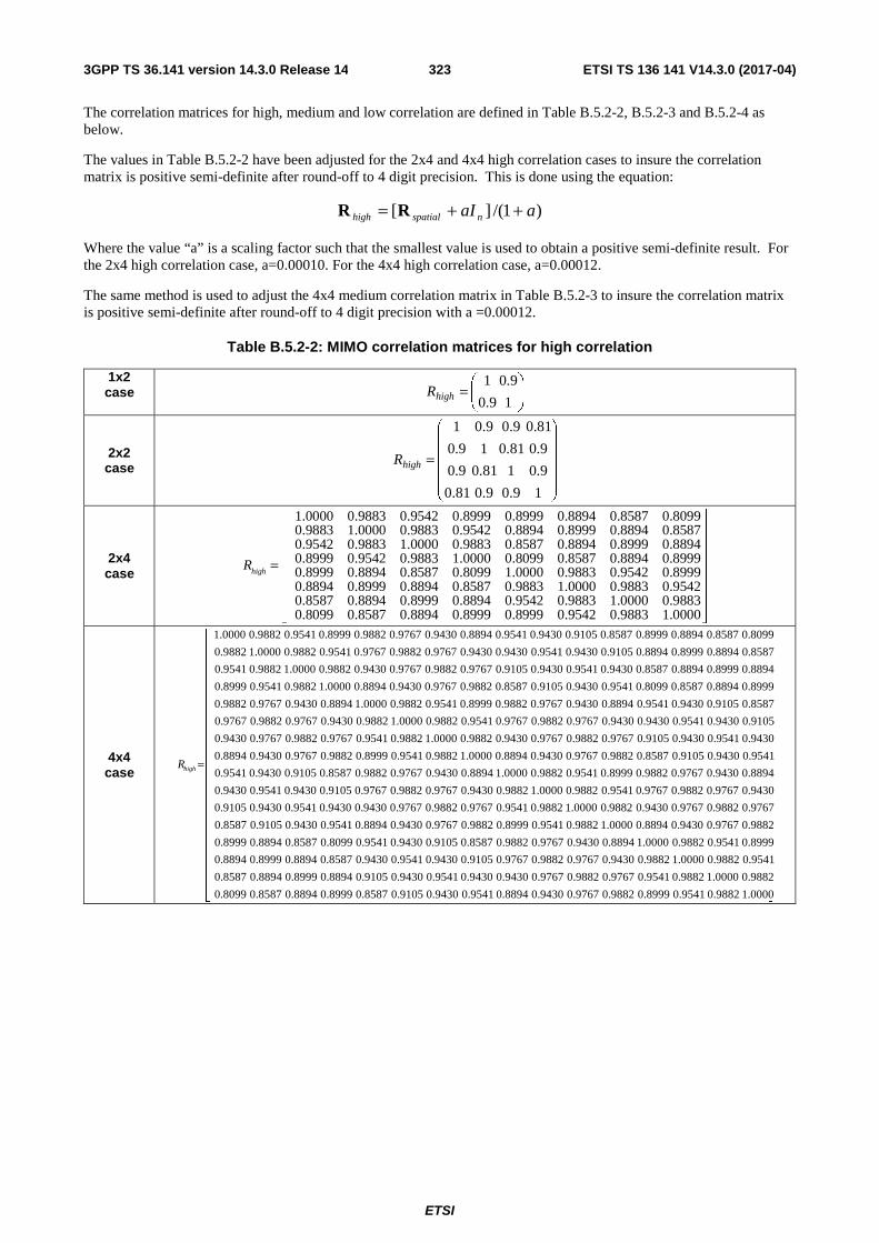
ETSI
ETSI TS 136 141 V14.3.0 (2017-04)3233GPP TS 36.141 version 14.3.0 Release 14
The correlation matrices for high, medium and low correlation are defined in Table B.5.2-2, B.5.2-3 and B.5.2-4 as below.
The values in Table B.5.2-2 have been adjusted for the 2x4 and 4x4 high correlation cases to insure the correlation matrix is positive semi-definite after round-off to 4 digit precision. This is done using the equation:
Where the value “a” is a scaling factor such that the smallest value is used to obtain a positive semi-definite result. For the 2x4 high correlation case, a=0.00010. For the 4x4 high correlation case, a=0.00012.
The same method is used to adjust the 4x4 medium correlation matrix in Table B.5.2-3 to insure the correlation matrix is positive semi-definite after round-off to 4 digit precision with a =0.00012.
Table B.5.2-2: MIMO correlation matrices for high correlation
1x2 case
2x2 case
2x4 case
4x4 case
)1/(][ aaI nspatialhigh ++= RR
⎟⎟⎠
⎞⎜⎜⎝
⎛=
19.0
9.01highR
⎟⎟⎟⎟⎟
⎠
⎞
⎜⎜⎜⎜⎜
⎝
⎛
=
19.09.081.0
9.0181.09.0
9.081.019.0
81.09.09.01
highR
1.0000 0.9883 0.9542 0.8999 0.8999 0.8894 0.8587 0.8099 0.9883 1.0000 0.9883 0.9542 0.8894 0.8999 0.8894 0.8587 0.9542 0.9883 1.0000 0.9883
highR = 0.8587 0.8894 0.8999 0.8894
0.8999 0.9542 0.9883 1.0000 0.8099 0.8587 0.8894 0.8999 0.8999 0.8894 0.8587 0.8099 1.0000 0.9883 0.9542 0.8999 0.8894 0.8999 0.8894 0.8587 0.9883 1.0000 0.9883 0.9542 0.8587 0.8894 0.8999 0.8894 0.9542 0.9883 1.0000 0.9883 0.8099 0.8587 0.8894 0.8999 0.8999 0.9542 0.9883 1.0000
⎡ ⎤⎢ ⎥⎢ ⎥⎢ ⎥⎢ ⎥⎢ ⎥⎢ ⎥⎢ ⎥⎣ ⎦
⎥⎥⎥⎥⎥⎥⎥⎥⎥⎥⎥⎥⎥⎥⎥⎥⎥⎥⎥⎥⎥⎥⎥
⎦
⎤
⎢⎢⎢⎢⎢⎢⎢⎢⎢⎢⎢⎢⎢⎢⎢⎢⎢⎢⎢⎢⎢⎢⎢
⎣
⎡
=
1.0000 0.9882 0.9541 0.8999 0.9882 0.9767 0.9430 0.8894 0.9541 0.9430 0.9105 0.8587 0.8999 0.8894 0.8587 0.8099
0.9882 1.0000 0.9882 0.9541 0.9767 0.9882 0.9767 0.9430 0.9430 0.9541 0.9430 0.9105 0.8894 0.8999 0.8894 0.8587
0.9541 0.9882 1.0000 0.9882 0.9430 0.9767 0.9882 0.9767 0.9105 0.9430 0.9541 0.9430 0.8587 0.8894 0.8999 0.8894
0.8999 0.9541 0.9882 1.0000 0.8894 0.9430 0.9767 0.9882 0.8587 0.9105 0.9430 0.9541 0.8099 0.8587 0.8894 0.8999
0.9882 0.9767 0.9430 0.8894 1.0000 0.9882 0.9541 0.8999 0.9882 0.9767 0.9430 0.8894 0.9541 0.9430 0.9105 0.8587
0.9767 0.9882 0.9767 0.9430 0.9882 1.0000 0.9882 0.9541 0.9767 0.9882 0.9767 0.9430 0.9430 0.9541 0.9430 0.9105
0.9430 0.9767 0.9882 0.9767 0.9541 0.9882 1.0000 0.9882 0.9430 0.9767 0.9882 0.9767 0.9105 0.9430 0.9541 0.9430
0.8894 0.9430 0.9767 0.9882 0.8999 0.9541 0.9882 1.0000 0.8894 0.9430 0.9767 0.9882 0.8587 0.9105 0.9430 0.9541
0.9541 0.9430 0.9105 0.8587 0.9882 0.9767 0.9430 0.8894 1.0000 0.9882 0.9541 0.8999 0.9882 0.9767 0.9430 0.8894
0.9430 0.9541 0.9430 0.9105 0.9767 0.9882 0.9767 0.9430 0.9882 1.0000 0.9882 0.9541 0.9767 0.9882 0.9767 0.9430
0.9105 0.9430 0.9541 0.9430 0.9430 0.9767 0.9882 0.9767 0.9541 0.9882 1.0000 0.9882 0.9430 0.9767 0.9882 0.9767
0.8587 0.9105 0.9430 0.9541 0.8894 0.9430 0.9767 0.9882 0.8999 0.9541 0.9882 1.0000 0.8894 0.9430 0.9767 0.9882
0.8999 0.8894 0.8587 0.8099 0.9541 0.9430 0.9105 0.8587 0.9882 0.9767 0.9430 0.8894 1.0000 0.9882 0.9541 0.8999
0.8894 0.8999 0.8894 0.8587 0.9430 0.9541 0.9430 0.9105 0.9767 0.9882 0.9767 0.9430 0.9882 1.0000 0.9882 0.9541
0.8587 0.8894 0.8999 0.8894 0.9105 0.9430 0.9541 0.9430 0.9430 0.9767 0.9882 0.9767 0.9541 0.9882 1.0000 0.9882
0.8099 0.8587 0.8894 0.8999 0.8587 0.9105 0.9430 0.9541 0.8894 0.9430 0.9767 0.9882 0.8999 0.9541 0.9882 1.0000
highR

ETSI
ETSI TS 136 141 V14.3.0 (2017-04)3243GPP TS 36.141 version 14.3.0 Release 14
Table B.5.2-3: MIMO correlation matrices for medium correlation
1x2 case N/A
2x2 case
1.0000 0.9000 0.3000 0.27000.9000 1.0000 0.2700 0.30000.3000 0.2700 1.0000 0.90000.2700 0.3000 0.9000 1.0000
mediumR
⎛ ⎞⎜ ⎟=⎜ ⎟⎜ ⎟⎝ ⎠
2x4 case
1.0000 0.9884 0.9543 0.9000 0.3000 0.2965 0.2863 0.2700 0.9884 1.0000 0.9884 0.9543 0.2965 0.3000 0.2965 0.2863 0.9543 0.9884 1.0000 0
mediumR =
.9884 0.2863 0.2965 0.3000 0.2965 0.9000 0.9543 0.9884 1.0000 0.2700 0.2863 0.2965 0.3000 0.3000 0.2965 0.2863 0.2700 1.0000 0.9884 0.9543 0.9000 0.2965 0.3000 0.2965 0.2863 0.9884 1.0000 0.9884 0.9543 0.2863 0.2965 0.3000 0.2965 0.9543 0.9884 1.0000 0.9884 0.2700 0.2863 0.2965 0.3000 0.9000 0.9543 0.9884 1.0000
⎛ ⎞⎜ ⎟⎜ ⎟⎜ ⎟⎜ ⎟⎜ ⎟⎜ ⎟⎜ ⎟⎝ ⎠
4x4 case
1.0000 0.9882 0.9541 0.8999 0.8747 0.8645 0.8347 0.7872 0.5855 0.5787 0.5588 0.5270 0.3000 0.2965 0.2862 0.2700 0.9882 1.0000 0.9882 0.
mediumR =
9541 0.8645 0.8747 0.8645 0.8347 0.5787 0.5855 0.5787 0.5588 0.2965 0.3000 0.2965 0.2862 0.9541 0.9882 1.0000 0.9882 0.8347 0.8645 0.8747 0.8645 0.5588 0.5787 0.5855 0.5787 0.2862 0.2965 0.3000 0.2965 0.8999 0.9541 0.9882 1.0000 0.7872 0.8347 0.8645 0.8747 0.5270 0.5588 0.5787 0.5855 0.2700 0.2862 0.2965 0.3000 0.8747 0.8645 0.8347 0.7872 1.0000 0.9882 0.9541 0.8999 0.8747 0.8645 0.8347 0.7872 0.5855 0.5787 0.5588 0.5270 0.8645 0.8747 0.8645 0.8347 0.9882 1.0000 0.9882 0.9541 0.8645 0.8747 0.8645 0.8347 0.5787 0.5855 0.5787 0.5588 0.8347 0.8645 0.8747 0.8645 0.9541 0.9882 1.0000 0.9882 0.8347 0.8645 0.8747 0.8645 0.5588 0.5787 0.5855 0.5787 0.7872 0.8347 0.8645 0.8747 0.8999 0.9541 0.9882 1.0000 0.7872 0.8347 0.8645 0.8747 0.5270 0.5588 0.5787 0.5855 0.5855 0.5787 0.5588 0.5270 0.8747 0.8645 0.8347 0.7872 1.0000 0.9882 0.9541 0.8999 0.8747 0.8645 0.8347 0.7872 0.5787 0.5855 0.5787 0.5588 0.8645 0.8747 0.8645 0.8347 0.9882 1.0000 0.9882 0.9541 0.8645 0.8747 0.8645 0.8347 0.5588 0.5787 0.5855 0.5787 0.8347 0.8645 0.8747 0.8645 0.9541 0.9882 1.0000 0.9882 0.8347 0.8645 0.8747 0.8645 0.5270 0.5588 0.5787 0.5855 0.7872 0.8347 0.8645 0.8747 0.8999 0.9541 0.9882 1.0000 0.7872 0.8347 0.8645 0.8747 0.3000 0.2965 0.2862 0.2700 0.5855 0.5787 0.5588 0.5270 0.8747 0.8645 0.8347 0.7872 1.0000 0.9882 0.9541 0.8999 0.2965 0.3000 0.2965 0.2862 0.5787 0.5855 0.5787 0.5588 0.8645 0.8747 0.8645 0.8347 0.9882 1.0000 0.9882 0.9541 0.2862 0.2965 0.3000 0.2965 0.5588 0.5787 0.5855 0.5787 0.8347 0.8645 0.8747 0.8645 0.9541 0.9882 1.0000 0.9882 0.2700 0.2862 0.2965 0.3000 0.5270 0.5588 0.5787 0.5855 0.7872 0.8347 0.8645 0.8747 0.8999 0.9541 0.9882 1.0000
⎛ ⎞⎜ ⎟⎜ ⎟⎜ ⎟⎜ ⎟⎜ ⎟⎜ ⎟⎜ ⎟⎜ ⎟⎜ ⎟⎜ ⎟⎜ ⎟⎜ ⎟⎜ ⎟⎜ ⎟⎜ ⎟⎝ ⎠
Table B.5.2-4: MIMO correlation matrices for low correlation
1x2 case
1x4 case
2x2 case
2x4 case
4x4 case
In Table B.5.2-4, is a identity matrix.
NOTE: For completeness, the 1x2 cases were defined for high, medium and low correlation but for Rel-8 onwards for 1Tx, performance requirements exist only for low correlation.
B.5A Multi-Antenna channel models using cross polarized antennas
The MIMO channel correlation matrices defined in B.5A apply to two cases as presented below:
- One TX antenna and multiple RX antennas case, with cross polarized antennas used at eNodeB;
- Multiple TX antennas and multiple RX antennas case, with cross polarized antennas used at both UE and eNodeB.
2I=lowR
4I=lowR
4I=lowR
8I=lowR
16I=lowR
dI dd ×

ETSI
ETSI TS 136 141 V14.3.0 (2017-04)3253GPP TS 36.141 version 14.3.0 Release 14
The cross-polarized antenna elements with +/-45 degrees polarization slant angles are deployed at eNB. For one TX antenna case, antenna element with +90 degree polarization slant angle is deployed at UE. For multiple TX antennas case, cross-polarized antenna elements with +90/0 degrees polarization slant angles are deployed at UE.
For the cross-polarized antennas, the N antennas are labelled such that antennas for one polarization are listed from 1 to N/2 and antennas for the other polarization are listed from N/2+1 to N, where N is the number of TX or RX antennas.
B.5A.1 Definition of MIMO Correlation Matrices using cross polarized antennas
For the channel spatial correlation matrix, the following is used:
( ) TSpat UL UE UL eNB ULR P R R P= ⊗ Γ ⊗
Where
- is the spatial correlation matrix at the UE with same polarization,
- is the spatial correlation matrix at the eNB with same polarization,
- ULΓ is a polarization correlation matrix,
- ULP is a permutation matrix, and
- denotes transpose.
Table B.5A.1-1 defines the polarization correlation matrix.
Table B.5A.1-1: Polarization correlation matrix
One TX antenna Multiple TX antennas
Polarization correlation matrix
1
1ULΓγ
γ−⎡ ⎤
= ⎢ ⎥−⎣ ⎦
1 0 0
1 0 0
0 0 1
0 0 1
ULΓ
γγ
γγ
−⎡ ⎤⎢ ⎥−⎢ ⎥=⎢ ⎥⎢ ⎥⎣ ⎦
The matrix ULP is defined as
1 ( 1) 2( 1) , 1, , , 1, , / 2
( , ) 1 ( 1) 2( / 2) , 1, , , / 2 1,...,
0UL
for a j Nr i and b j Nr i i Nr j Nt
a b for a j Nr i and b j Nt Nr Nr i i Nr j Nt Nt
otherwise
⎧ = − + = − + = = ⎡ ⎤⎢ ⎥⎪
= = − + = − − + = = +⎡ ⎤⎨ ⎢ ⎥⎪⎩
P
L L
L
where Nt and Nr is the number of TX and RX antennas respectively, and •⎡ ⎤⎢ ⎥ is the ceiling operator.
The matrix ULP is used to map the spatial correlation coefficients in accordance with the antenna element labelling
system described in B.5A.
B.5A.2 Spatial Correlation Matrices at UE and eNB sides
B.5A.2.1 Spatial Correlation Matrices at UE side
For 1-antenna transmitter, 1UER = .
For 2-antenna transmitter using one pair of cross-polarized antenna elements, 1UER = .
UER
eNBR
T)(•

ETSI
ETSI TS 136 141 V14.3.0 (2017-04)3263GPP TS 36.141 version 14.3.0 Release 14
For 4-antenna transmitter using two pairs of cross-polarized antenna elements, *
1
1UER
ββ
⎛ ⎞= ⎜ ⎟⎝ ⎠
.
B.5A.2.2 Spatial Correlation Matrices at eNB side
For 2-antenna receiver using one pair of cross-polarized antenna elements, 1eNBR = .
For 4-antenna receiver using two pairs of cross-polarized antenna elements, *
1
1eNBR
αα
⎛ ⎞= ⎜ ⎟⎝ ⎠
.
For 8-antenna receiver using four pairs of cross-polarized antenna elements,
1/9 4/9
1/9* 1/9 4/9
4/9* 1/9* 1/9
* 4/9* 1/9*
11
11
eNBR
α α αα α αα α αα α α
⎛ ⎞⎜ ⎟
= ⎜ ⎟⎜ ⎟⎝ ⎠
.
B.5A.3 MIMO Correlation Matrices using cross polarized antennas The values for parameters α, β and γ for low spatial correlation are given in Table B.5A.3-1.
Table B.5A.3-1: Values for parameters α, β and γ
Low spatial correlation � � � 0 0 0
Note 1: Value of α applies when more than one pair of cross-polarized antenna elements at eNB side. Note 2: Value of β applies when more than one pair of cross-polarized antenna elements at UE side.
The correlation matrices for low spatial correlation are defined in Table B.5A.3-2 as below.
Table B.5A.3-2: MIMO correlation matrices for low spatial correlation
1x8 case 8lowR = I
2x8 case 16lowR = I
In Table B.5A.3-2, is a identity matrix. dI dd ×
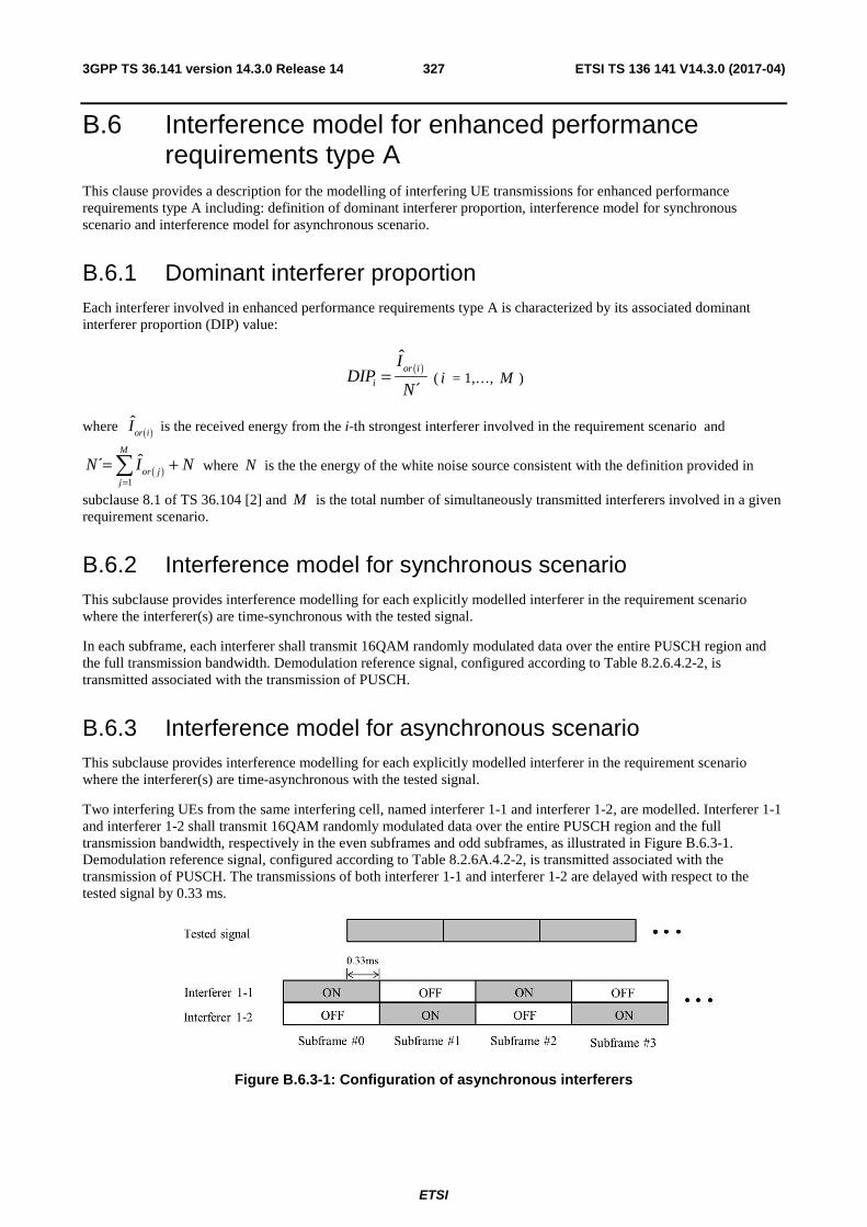
ETSI
ETSI TS 136 141 V14.3.0 (2017-04)3273GPP TS 36.141 version 14.3.0 Release 14
B.6 Interference model for enhanced performance requirements type A
This clause provides a description for the modelling of interfering UE transmissions for enhanced performance requirements type A including: definition of dominant interferer proportion, interference model for synchronous scenario and interference model for asynchronous scenario.
B.6.1 Dominant interferer proportion Each interferer involved in enhanced performance requirements type A is characterized by its associated dominant interferer proportion (DIP) value:
( )ˆ
´or i
i
IDIP
N= ( i = 1,…, M )
where ( )ˆor iI is the received energy from the i-th strongest interferer involved in the requirement scenario and
( )1
ˆ´M
or jj
N I N=
= +∑ where N is the the energy of the white noise source consistent with the definition provided in
subclause 8.1 of TS 36.104 [2] and M is the total number of simultaneously transmitted interferers involved in a given requirement scenario.
B.6.2 Interference model for synchronous scenario This subclause provides interference modelling for each explicitly modelled interferer in the requirement scenario where the interferer(s) are time-synchronous with the tested signal.
In each subframe, each interferer shall transmit 16QAM randomly modulated data over the entire PUSCH region and the full transmission bandwidth. Demodulation reference signal, configured according to Table 8.2.6.4.2-2, is transmitted associated with the transmission of PUSCH.
B.6.3 Interference model for asynchronous scenario This subclause provides interference modelling for each explicitly modelled interferer in the requirement scenario where the interferer(s) are time-asynchronous with the tested signal.
Two interfering UEs from the same interfering cell, named interferer 1-1 and interferer 1-2, are modelled. Interferer 1-1 and interferer 1-2 shall transmit 16QAM randomly modulated data over the entire PUSCH region and the full transmission bandwidth, respectively in the even subframes and odd subframes, as illustrated in Figure B.6.3-1. Demodulation reference signal, configured according to Table 8.2.6A.4.2-2, is transmitted associated with the transmission of PUSCH. The transmissions of both interferer 1-1 and interferer 1-2 are delayed with respect to the tested signal by 0.33 ms.
Figure B.6.3-1: Configuration of asynchronous interferers

ETSI
ETSI TS 136 141 V14.3.0 (2017-04)3283GPP TS 36.141 version 14.3.0 Release 14
Annex C (normative): Characteristics of the interfering signals <Text will be added.>
The interfering signal shall be a PUSCH containing data and reference symbols. Normal cyclic prefix is used. The data content shall be uncorrelated to the wanted signal and modulated according to clause 5 of TS36.211. Mapping of PUSCH modulation to receiver requirement are specified in Table C.1.
Table C.1: Modulation of the interfering signal
Receiver requirement Modulation In-channel selectivity 16QAM
Adjacent channel selectivity and narrow-band blocking
QPSK
Blocking QPSK Receiver intermodulation QPSK

ETSI
ETSI TS 136 141 V14.3.0 (2017-04)3293GPP TS 36.141 version 14.3.0 Release 14
Annex D (normative): Environmental requirements for the BS equipment
D.1 General For each test in the present document, the environmental conditions under which the BS is to be tested are defined.
D.2 Normal test environment When a normal test environment is specified for a test, the test should be performed within the minimum and maximum limits of the conditions stated in Table D.1.
Table D.1: Limits of conditions for Normal Test Environment
Condition Minimum Maximum Barometric pressure 86 kPa 106 kPa Temperature 15°C 30°C Relative Humidity 20 % 85 % Power supply Nominal, as declared by the manufacturer Vibration Negligible
The ranges of barometric pressure, temperature and humidity represent the maximum variation expected in the uncontrolled environment of a test laboratory. If it is not possible to maintain these parameters within the specified limits, the actual values shall be recorded in the test report.
NOTE: This may, for instance, be the case for measurements of radiated emissions performed on an open field test site.
D.3 Extreme test environment The manufacturer shall declare one of the following:
1) the equipment class for the equipment under test, as defined in the IEC 60 721-3-3 [6];
2) the equipment class for the equipment under test, as defined in the IEC 60 721-3-4 [7];
3) the equipment that does not comply to the mentioned classes, the relevant classes from IEC 60 721 documentation for Temperature, Humidity and Vibration shall be declared.
NOTE: Reduced functionality for conditions that fall outside of the standard operational conditions is not tested in the present document. These may be stated and tested separately.
D.3.1 Extreme temperature When an extreme temperature test environment is specified for a test, the test shall be performed at the standard minimum and maximum operating temperatures defined by the manufacturer's declaration for the equipment under test.
Minimum temperature:
The test shall be performed with the environment test equipment and methods including the required environmental phenomena into the equipment, conforming to the test procedure of IEC 60 068-2-1 [8].
Maximum temperature:

ETSI
ETSI TS 136 141 V14.3.0 (2017-04)3303GPP TS 36.141 version 14.3.0 Release 14
The test shall be performed with the environmental test equipment and methods including the required environmental phenomena into the equipment, conforming to the test procedure of IEC 60 068-2-2 [9].
NOTE: It is recommended that the equipment is made fully operational prior to the equipment being taken to its lower operating temperature.
D.4 Vibration When vibration conditions are specified for a test, the test shall be performed while the equipment is subjected to a vibration sequence as defined by the manufacturer’s declaration for the equipment under test. This shall use the environmental test equipment and methods of inducing the required environmental phenomena in to the equipment, conforming to the test procedure of IEC 60 068-2-6 [10]. Other environmental conditions shall be within the ranges specified in clause D.2.
NOTE: The higher levels of vibration may induce undue physical stress in to equipment after a prolonged series of tests. The testing body should only vibrate the equipment during the RF measurement process.
D.5 Power supply When extreme power supply conditions are specified for a test, the test shall be performed at the standard upper and lower limits of operating voltage defined by manufacturer's declaration for the equipment under test.
Upper voltage limit:
The equipment shall be supplied with a voltage equal to the upper limit declared by the manufacturer (as measured at the input terminals to the equipment). The tests shall be carried out at the steady state minimum and maximum temperature limits declared by the manufacturer for the equipment, to the methods described in IEC 60 068-2-1 [8] Test Ab/Ad and IEC 60 068-2-2 [9] Test Bb/Bd: Dry Heat.
Lower voltage limit:
The equipment shall be supplied with a voltage equal to the lower limit declared by the manufacturer (as measured at the input terminals to the equipment). The tests shall be carried out at the steady state minimum and maximum temperature limits declared by the manufacturer for the equipment, to the methods described in IEC 60 068-2-1 [8] Test Ab/Ad and IEC 60 068-2-2 [9] Test Bb/Bd: Dry Heat.
D.6 Measurement of test environments The measurement accuracy of the BS test environments defined in Annex D, Test environments shall be.
Pressure: ±5 kPa. Temperature: ±2 degrees. Relative Humidity: ±5 %. DC Voltage: ±1,0 %. AC Voltage: ±1,5 %. Vibration: 10 %. Vibration frequency: 0,1 Hz.
The above values shall apply unless the test environment is otherwise controlled and the specification for the control of the test environment specifies the uncertainty for the parameter.

ETSI
ETSI TS 136 141 V14.3.0 (2017-04)3313GPP TS 36.141 version 14.3.0 Release 14
Annex E (normative): General rules for statistical testing <Text will be added.>
ETSI
ETSI TS 136 141 V14.3.0 (2017-04)3323GPP TS 36.141 version 14.3.0 Release 14
Annex F (normative): Global In-Channel TX-Test
F.1 General The global in-channel Tx test enables the measurement of all relevant parameters that describe the in-channel quality of the output signal of the TX under test in a single measurement process.
The parameters describing the in-channel quality of a transmitter, however, are not necessarily independent. The algorithm chosen for description inside this annex places particular emphasis on the exclusion of all interdependencies among the parameters.
F.2.1 Basic principle The process is based on the comparison of the actual output signal of the TX under test, received by an ideal receiver, with a reference signal, that is generated by the measuring equipment and represents an ideal error free received signal. All signals are represented as equivalent (generally complex) baseband signals.
The description below uses numbers and illustrations as examples. These numbers are taken from frame structure 1 with normal CP length and a transmission bandwidth configuration of NRB = 100. The application of the text below, however, is not restricted to this parameterset.
F.2.2 Output signal of the TX under test The output signal of the TX under test is acquired by the measuring equipment and stored for further processsing. It is sampled at a sampling rate of 30.72 Msps and it is named z(ν). In the time domain it comprises at least 1 frame:: z(ν). It is modelled as a signal with the following parameters: demodulated data content, carrier frequency, amplitude and phase for each subcarrier.
F.2.3 Reference signal Two types of reference signal are defined:
The reference signal i1(ν) is constructed by the measuring equipment according to the relevant TX specifications, using the following parameters: demodulated data content, nominal carrier frequency, nominal amplitude and phase for each subcarrier. It is represented as a sequence of samples at a sampling rate of 30.72 Msps in the time domain. The structure of the signal is described in the testmodells.
The reference signal i2(ν) is constructed by the measuring equipment according to the relevant TX specifications, using the following parameters: restricted data content: nominal Reference Symbols and the Primary Synchronisation Channel, (all other modulation symbols are set to 0 V), nominal carrier frequency, nominal amplitude and phase for each applicable subcarrier, nominal timing. It is represented as a sequence of samples at a sampling rate of 30.72 Msps in the time domain.
F.2.4 Measurement results The measurement results, achieved by the global in channel TX test are the following:
- Carrier Frequency error
- EVM (Error Vector Magnitude)
- Resource Element TX power
- RS TX power (RSTP)

ETSI
ETSI TS 136 141 V14.3.0 (2017-04)3333GPP TS 36.141 version 14.3.0 Release 14
- OFDM Symbol TX power (OSTP)
Other side results are: residual amplitude- and phase response of the TX chain after equalisation.
F.2.5 Measurement points
Resource element TX power is measured after the FFT as described below. EVM is calculated after the Equalizer (Ampl./ Phase correction). The result of the frequency synchronisation is the frequency offset. It is performed in the pre- and/or post-FFT domain. The FFT window of 2048 samples out of 2194 samples (data +CP) in the time domain is selected in the box CP removal.
BS under Test
RF-correc-tion
FFT 2048
Per subcarrier Ampl. /Phase correction
Symbol Detection / decoding
100 RBs, 1200 sub carr
CP- remov
EVM
RETP
Synchronisation, time/frequ
Figure E.2.5-1: Measurement points
F.3.1 Pre FFT minimization process Sample Timing, Carrier Frequency in z(ν) are varied in order to minimise the difference between z(ν) and i1 (ν) , after the amplitude ratio of z(ν) and i1 (ν) has been scaled. Best fit (minimum difference) is achieved when the RMS difference value between z(ν) and i(ν) is an absolute minimum.
The carrier frequency variation is the measurement result: Carrier Frequency Error.
From the acquired samples one carrier frequency error can be derived.
Note 1: The minimisation process, to derive the RF error can be supported by Post FFT operations. However the minimisation process defined in the pre FFT domain comprises all acquired samples (i.e. it does not exclude the samples inbetween the FFT widths and it does not exclude the bandwidth outside the transmission bandwidth configuration.
Note 2: The algorithm would allow to derive Carrier Frequency error and Sample Frequency error of the TX under test separately. However there are no requirements for Sample Frequeny error. Hence the algorithm models the RF and the sample frequency commonly (not independently). It returns one error and does not distinuish between both.
After this process the samples z(ν) are called z0(ν).
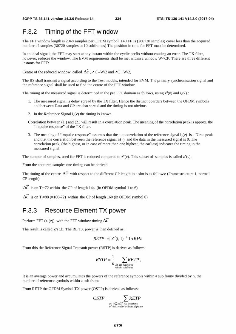
ETSI
ETSI TS 136 141 V14.3.0 (2017-04)3343GPP TS 36.141 version 14.3.0 Release 14
F.3.2 Timing of the FFT window The FFT window length is 2048 samples per OFDM symbol. 140 FFTs (286720 samples) cover less than the acquired number of samples (30720 samples in 10 subframes) The position in time for FFT must be determined.
In an ideal signal, the FFT may start at any instant within the cyclic prefix without causing an error. The TX filter, however, reduces the window. The EVM requirements shall be met within a window W<CP. There are three different instants for FFT:
Centre of the reduced window, called c~Δ , ΔC –W/2 and ΔC +W/2,
The BS shall transmit a signal according to the Test models, intended for EVM. The primary synchronisation signal and the reference signal shall be used to find the centre of the FFT window.
The timing of the measured signal is determined in the pre FFT domain as follows, using z0(ν) and i2(ν) :
1. The measured signal is delay spread by the TX filter. Hence the distinct boarders between the OFDM symbols and between Data and CP are also spread and the timing is not obvious.
2. In the Reference Signal i2(ν) the timing is known.
Correlation between (1.) and (2.) will result in a correlation peak. The meaning of the correlation peak is approx. the “impulse response” of the TX filter.
3. The meaning of “impulse response” assumes that the autocorrelation of the reference signal i2(ν) is a Dirac peak and that the correlation between the reference signal i2(ν) and the data in the measured signal is 0. The correlation peak, (the highest, or in case of more than one highest, the earliest) indicates the timing in the measured signal.
The number of samples, used for FFT is reduced compared to z0(ν). This subset of samples is called z’(ν).
From the acquired samples one timing can be derived.
The timing of the centre c~Δ with respect to the different CP length in a slot is as follows: (Frame structure 1, normal CP length)
c~Δ is on Tf=72 within the CP of length 144 (in OFDM symbol 1 to 6)
c~Δ is on Tf=88 (=160-72) within the CP of length 160 (in OFDM symbol 0)
F.3.3 Resource Element TX power
Perform FFT (z’(ν)) with the FFT window timing c~Δ
The result is called Z’(t,f). The RE TX power is then defined as:
KHzRETP 15|f)(t,Z| 2′=
From this the Reference Signal Transmit power (RSTP) is derives as follows:
∑=subframewithinlocationsRERS
RETPn
RSTP1
,
It is an average power and accumulates the powers of the reference symbols within a sub frame divided by n, the number of reference symbols within a sub frame.
From RETP the OFDM Symbol TX power (OSTP) is derived as follows:
∑=subframewithinsymbolthof
locationsRENNall
RETPOSTP
4
RBsc
DLRB

ETSI
ETSI TS 136 141 V14.3.0 (2017-04)3353GPP TS 36.141 version 14.3.0 Release 14
It accumulates all sub carrier powers of the 4th OFDM symbol. The 4th (out of 14 OFDM symbols within a subframe (in case of frame type 1 , normal CP length)) contains exclusively PDSCH.
From the acquired samples 10 values for each RSTP and OSTP can be derived.
F.3.4 Post FFT equalisation
Perform 140 FFTs on z’(ν), one for each OFDM symbol comprising the full frame with the FFT window timing c~Δ . (in case of frame type 1 , normal CP length) The result is an array of samples, 140 in the time axis t times 2048 in the frequency axis f.
The equalizer coefficients )(~ fa and )(~ fϕ are determined as follows:
1. Calculate the complex ratios (amplitude and phase) of the post-FFT acquired signal ),(' ftZ and the post-FFT
Ideal signal ),(2 ftI , for each reference symbol, over 10 subframes. This process creates a set of complex
ratios:
),(
),(').,(
2
),(
ftI
ftZefta ftj =ϕ
2. Perform time averaging at each reference signal subcarrier of the complex ratios, the time-averaging length is 10
subframes. Prior to the averaging of the phases ( )fti ,ϕ an unwrap operation must be performed according to
the following definition: The unwrap operation corrects the radian phase angles of ( )fti ,ϕ by adding multiples
of 2*PI when absolute phase jumps between consecutive time instances ti are greater then or equal to the jump tolerance of PI radians. This process creates an average amplitude and phase for each reference signal subcarrier (i.e. every third subcarrier with the exception of the reference subcarrier spacing across the DC subcarrier).
( )N
ftafa
N
ii∑
== 1
,)(
( )N
ftf
N
ii∑
== 1
,)(
ϕϕ
Where N is the number of reference symbol time-domain locations ti from Z’(f,t) for each reference signal subcarrier f .
3. The equalizer coefficients for amplitude and phase )(ˆ fa and )(ˆ fϕ at the reference signal subcarriers are
obtained by computing the moving average in the frequency domain of the time-averaged reference signal subcarriers, i.e. every third subcarrier. The moving average window size is 19. For reference subcarriers at or near the edge of the channel the window size is reduced accordingly as per figure F. 3.4.
4. Perform linear interpolation from the equalizer coefficients )(ˆ fa and )(ˆ fϕ to compute coefficients )(~ fa ,
)(~ fϕ for each subcarrier.
The equalized samples are called Z’eq(f,t).

ETSI
ETSI TS 136 141 V14.3.0 (2017-04)3363GPP TS 36.141 version 14.3.0 Release 14
The subsequent 7 subcarriers are averaged over 5, 7 .. 17 subcarriers
From the 10th subcarrier onwards the window size is 19 until the upper edge of the channel is reached and the window size reduces back to 1
The first reference subcarrier is not averaged
The second reference subcarrier is the average of the first three subcarriers
Reference subcarriers
Figure F.3.4-1: Reference subcarrier smoothing in the frequency domain
F.4.1 EVM For EVM create two sets of Z’eq(f,t)., according to the timing ”ΔC –W/2 and ΔC +W/2”, using the equalizer coefficients from F.3.4.
The equivalent ideal samples are calculated form i1(ν) (clause F.2.3) and are called I(f,t).
The EVM is the difference between the ideal waveform and the measured and equalized waveform.
( ) ( )( )∑∑
∑∑
∈∈
∈∈
−=
)(
2
)(
2
,
,,'
tFfTt
tFfeq
Tt
tfI
tfItfZ
EVM ,
where
T is the set of symbols with the considered modulation scheme being active within the subframe,
)(tF is the set of subcarriers within the RBSCN resource blocks with the considered modulation scheme being active in
symbol t,
),( ftI is the ideal signal reconstructed by the measurement equipment in accordance with relevant Test models,
),(' ftZ eq is the equalized signal under test.
Note1: Although the basic unit of measurement is one subframe, the equalizer is calculated over the entire 10 subframes measurement period to reduce the impact of noise in the reference symbols.
Note 2: Applicability of EVM calculation:
One EVM value is associated to 12 subcarriers times 1 subframe = pair of 2 RBs = 168 resource elements.

ETSI
ETSI TS 136 141 V14.3.0 (2017-04)3373GPP TS 36.141 version 14.3.0 Release 14
But only a reduced number of REs in this pair of 2 RBs contribute to EVM. Those are the PDSCH REs, containing the considered modulation scheme. Only those pairs of 2 RBs are evaluated with respect to EVM, which contain the maximum number of PDSCH REs. (EVM-relevant location in the time/frequency grid ) The others are not evaluated.
In specific:
- For bandwidth 1.4 MHz:
- Only the pairs of 2 RBs containing 138 PDSCH REs are used for EVM. Only those 138 REs contribute to EVM
- All pairs of 2 RBs, which contain less than 138 PDSCH REs, are not evaluated with respect to EVM.
- For all other Bandwidths:
- Only the pairs of 2 RBs containing 150 PDSCH REs are used for EVM. Only those 150 REs contribute to EVM
- All pairs of 2 RBs, which contain less than 150 PDSCH REs, are not evaluated with respect to EVM.
This restriction serves to avoid weighted averaging in F.4.2.
F.4.2 Averaged EVM EVM is averaged over all allocated EVM relevant locations in the frequency domain, and 10 consecutive downlink subframes (10 ms):
(The locations in the time-frequency grid are occupied irregularly, see Fig F.4.2-1)
EVM is derived by: square the EVM resultsin F.4.1, sum the squares over all EVM relevant locations in the time/frequency grid, divide the sum by the number of EVM relevant locations, square-root the quotient.
The EVM requirements should be tested against the maximum of the average EVM at the window W extremities of the EVM measurements:
Thus lEVM is calculated using ltt ~~ Δ=Δ in the expressions above and hEVM is calculated using htt ~~ Δ=Δ . (l
and h, low and high. Where l is the timing ΔC –W/2 and and high is the timing ΔC +W/2)
Thus we get:
)EVM ,EVMmax( l hfinalEVM =
For TDD special fields (DwPTS and GP) are not included in the averaging.
15 RBs

ETSI
ETSI TS 136 141 V14.3.0 (2017-04)3383GPP TS 36.141 version 14.3.0 Release 14
10 subframes �
Yellow: 136 EVM-relevant locations in the time/frequency grid
Blue: non PDSCH REs
White: RBs with non-maximum number of PDSCH REs
Figure F.4.2-1: Applicability of EVM calculation Example: E-TM1.x, E-TM3.x, 3MHz
F.4.2.1 Averaged EVM (TDD)
For TDD the averaging in the time domain can be calculated from subframes of different frames and should have a minimum of 10 subframes averaging length. TDD special fields (DwPTS and GP) are not included in the averaging.
EVM frame is derived by: Square the EVM results in a frame. Relevant for EVM are subframes in a frame, which are active in the DL, Ndl. Within these subframes, those RBs are relevant, that carry the maximum number of PDSCH REs (same as FDD). Sum the squares, divide the sum by the number of EVM relevant locations, square-root the quotient. (RMS)
The EVMframe is calculated, using the maximum of EVM frame at the window W extremities. Thus frame,lEVM is
calculated using ltt ~~ Δ=Δ and hframe,EVM is calculated using htt ~~ Δ=Δ . (l and h, low and high. Where l is the
timing ΔC –W/2 and and high is the timing ΔC +W/2)
)EVM ,EVMmax( ,frame,l hframeframeEVM =
In order to unite at least 10 subframes, consider the minimum integer number of radio frames, containing at least 10 EVM relevant subframes. Unite by RMS.
∑=
=frameN
kkframe
frame
EVMN
EVM1
2,
1, ⎥
⎥
⎤⎢⎢
⎡=
dlframe N
N10
The result, EVM , is compared against the limit.

ETSI
ETSI TS 136 141 V14.3.0 (2017-04)3393GPP TS 36.141 version 14.3.0 Release 14
Annex G (informative): Test Tolerances and Derivation of Test Requirements The Test Requirements in this specification have been calculated by relaxing the Minimum Requirements of the core specification using the Test Tolerances defined here. When the Test Tolerance is zero, the Test Requirement will be the same as the Minimum Requirement. When the Test Tolerance is non-zero, the Test Requirements will differ from the Minimum Requirements, and the formula used for this relaxation is given in the following tables.
The Test Tolerances are derived from Test System uncertainties, regulatory requirements and criticality to system performance. As a result, the Test Tolerances may sometimes be set to zero.
The test tolerances should not be modified for any reason e.g. to take account of commonly known test system errors (such as mismatch, cable loss, etc.).
Note that a formula for applying Test Tolerances is provided for all tests, even those with a test tolerance of zero. This is necessary in the case where the Test System uncertainty is greater than that allowed in clause 4.1.2. In this event, the excess error shall be subtracted from the defined test tolerance in order to generate the correct tightened Test Requirements as defined in this Annex.
[FFS: For example, a Test System having 0.9 dB uncertainty for test 6.2 Base Station maximum output power (which is 0.2 dB above the limit specified in clause 4.1.2) would subtract 0.2 dB from the Test Tolerance of 0.7 dB defined in this Annex. This new test tolerance of 0.5 dB would then be applied to the Minimum Requirement using the formula defined in Table G.2-1 to give a new range of ±2.5 dB of the manufacturer's rated output power.
Using this same approach for the case where a test had a test tolerance of 0 dB, an excess error of 0.2 dB would result in a modified test tolerance of -0.2 dB.]
Unless otherwise stated, the Test Tolerances in this annex apply to the Test System for testing BS that supports E-UTRA or E-UTRA with NB-IoT in-band/guard band operation or NB-IoT standalone operation.

ETSI
ETSI TS 136 141 V14.3.0 (2017-04)3403GPP TS 36.141 version 14.3.0 Release 14
G.1 Measurement of transmitter Table G.1-1: Derivation of Test Requirements (Transmitter tests)

ETSI
ETSI TS 136 141 V14.3.0 (2017-04)3413GPP TS 36.141 version 14.3.0 Release 14
Test Minimum Requirement in
TS 36.104
Test Tolerance
(TT)
Test Requirement in TS 36.141
6.2 Base station maximum output power
In normal conditions: within ±2 dB of manufacturer's rated output power In extreme conditions: within ±2.5 dB of manufacturer's rated output power Standalone NB-IoT In normal conditions: within ±2 dB of manufacturer's rated output power In extreme conditions: within ±2.5 dB of manufacturer's rated output power
Normal and extreme conditions: 0.7 dB, f ≤ 3.0GHz 1.0 dB, 3.0GHz < f ≤ 4.2GHz 1.0 dB 1.0 dB
Formula: Upper limit + TT, Lower limit - TT In normal conditions: within +2.7 dB and -2.7 dB of the manufacturer's rated output power, f ≤ 3.0GHz within +3.0 dB and -3.0 dB of the manufacturer's rated output power, 3.0GHz < f ≤ 4.2GHz In extreme conditions: within +3.2 dB and -3.2 dB of the manufacturer's rated output power, f ≤ 3.0GHz within +3.5 dB and -3.5 dB of the manufacturer's rated output power, 3.0GHz < f ≤ 4.2GHz In normal conditions: within +3.0 dB and -3.0 dB of the manufacturer's rated output power In extreme conditions: within +3.5 dB and -3.5 dB of the manufacturer's rated output power
6.3.2 Total power dynamic range
Total power dynamic range (dB): 1.4 MHz E-UTRA: 7.7
3 MHz E-UTRA: 11.7
5 MHz E-UTRA: 13.9 10 MHz E-UTRA: 16.9
15 MHz E-UTRA: 18.7
20 MHz E-UTRA: 20
0.4 dB Formula: Total power dynamic range – TT (dB) 1.4 MHz E-UTRA: 7.3
3 MHz E-UTRA: 11.3
5 MHz E-UTRA: 13.5
10 MHz E-UTRA: 16.5
15 MHz E-UTRA: 18.3
20 MHz E-UTRA: 19.6
6.3.3 NB-IoT RB power dynamic range for in-band or guard band operation
6 dB 0.4 dB Formula:
Minimum Requirement + TT

ETSI
ETSI TS 136 141 V14.3.0 (2017-04)3423GPP TS 36.141 version 14.3.0 Release 14
6.4.1 Transmitter OFF power
-85dBm/MHz. 2 dB, f ≤ 3.0GHz 2.5 dB, 3.0GHz < f ≤ 4.2GHz
Formula: Minimum Requirement + TT
6.4.2 Transmitter transient period
Transmitter transient period : off to on: 17 us on to off: 17 us
N/A Minimum Requirement
6.5.1 Frequency error
Frequency error limit ±0.05 ppm
12 Hz Formula: Frequency Error limit + TT
0.05 ppm + 12 Hz
6.5.2 EVM EVM limit: QPSK: 17.5 % 16QAM: 12.5 % 64QAM: 8 % 256QAM: 3.5%
1 % Formula:
EVM limit + TT
QPSK: 18.5 % 16QAM: 13.5 % 64QAM: 9 %
256QAM: 4.5%
6.5.3 Time alignment error
Time alignment error within 65 ns
25 ns Formula:
Time alignment error limit + TT
90 ns
6.5.4 DL RS power DL RS power
shall be within ±2.1 dB
0.8 dB, f ≤ 3.0GHz
1.1 dB, 3.0GHz < f ≤ 4.2GHz
Formula: Upper limit + TT Lower limit - TT DL RS power shall be within ±2.9 dB, f ≤ 3.0GHz DL RS power shall be within ±3.2 dB, 3.0GHz < f ≤ 4.2GHz
6.6.1 Occupied bandwidth
1.4 MHz 3 MHz 5 MHz 10 MHz 15 MHz 20 MHz Standalone NB-IoT: 200 kHz
0 kHz Formula: Minimum Requirement + TT

ETSI
ETSI TS 136 141 V14.3.0 (2017-04)3433GPP TS 36.141 version 14.3.0 Release 14
6.6.2 Adjacent Channel Leakage power Ratio (ACLR)
Paired spectrum ACLR: 45 dB for E-UTRA 45 dB for UTRA Standalone NB-IoT: 40 dB (ACLR1) 50 dB (ACLR2) Unpaired spectrum ACLR: 45 dB for E-UTRA 45 dB for 1.28 Mcps UTRA 45 dB for 3.84 Mcps UTRA 45 dB for 7.82 Mcps UTRA CACLR: 45 dB CACLR in Band 46: 35 dB or 40 dB Absolute limit -13dBm / MHz Absolute limit -15dBm / MHz
0.8 dB 0.8 dB 0.8 dB 0.8 dB 0.8 dB 0.8 dB 0.8 dB 0.8 dB 0.8 dB 0.8 dB 0 dB 0 dB
Formula: ACLR Minimum Requirement - TT Absolute limit +TT Paired spectrum ACLR: 44.2 dB 44.2 dB Standalone NB-IoT: 39.2 dB (ACLR1) 49.2 dB (ACLR2) Unpaired spectrum ACLR: 44.2 dB 44.2 dB 44.2 dB 44.2 dB CACLR: 44.2 dB CACLR in Band 46: 34.2 dB or 39.2 dB Absolute limit -13dBm / MHz Absolute limit -15dBm / MHz

ETSI
ETSI TS 136 141 V14.3.0 (2017-04)3443GPP TS 36.141 version 14.3.0 Release 14
6.6.3 Operating band unwanted emissions
For Wide Area BS: Category A, bands < 1GHz For 1.4MHz BW: Offsets < 2.8MHz -1dBm to -11dBm / 100kHz Offsets ≥ 2.8MHz -13dBm / 100kHz For 3MHz BW: Offsets < 3MHz -4.5dBm to -14.5dBm / 100kHz Offsets ≥ 3MHz -13dBm / 100kHz For 5, 10, 15, 20MHz BW: Offsets < 10MHz -7dBm to -14dBm / 100kHz Offsets ≥ 10MHz -13dBm / 100kHz Category A, bands > 1GHz For 1.4MHz BW: Offsets < 2.8MHz -1dBm to -11dBm / 100kHz Offsets ≥ 2.8MHz -13dBm / 1MHz For 3MHz BW: Offsets < 6MHz -5dBm to -15dBm / 100kHz Offsets ≥ 6MHz -13dBm / 1MHz For 5, 10, 15, 20MHz BW: Offsets < 10MHz -7dBm to -14dBm / 100kHz Offsets ≥ 10MHz -13dBm / 1MHz Category B, bands < 1GHz For 1.4MHz BW: Offsets < 2.8MHz -1dBm to -11dBm / 100kHz Offsets ≥ 2.8MHz -16dBm / 100kHz For 3MHz BW: Offsets < 6MHz -5dBm to -15dBm / 100kHz Offsets ≥ 6MHz -16dBm / 100kHz
1.5dB 0dB 1.5dB 0dB 1.5dB 0dB 1.5dB, f ≤ 3.0GHz 1.8dB, 3.0GHz < f ≤ 4.2GHz 0dB 1.5dB, f ≤ 3.0GHz 1.8dB, 3.0GHz < f ≤ 4.2GHz 0dB 1.5dB, f ≤ 3.0GHz 1.8dB, 3.0GHz < f ≤ 4.2GHz 0dB 1.5dB 0dB 1.5dB 0dB
Formula: Minimum Requirement + TT

ETSI
ETSI TS 136 141 V14.3.0 (2017-04)3453GPP TS 36.141 version 14.3.0 Release 14
For 5, 10, 15, 20MHz BW: Offsets < 10MHz -7dBm to -14dBm / 100kHz Offsets ≥ 10MHz -16dBm / 100kHz Category B, bands > 1GHz For 1.4MHz BW: Offsets < 2.8MHz -1dBm to -11dBm / 100kHz Offsets ≥ 2.8MHz -15dBm / 1MHz For 3MHz BW: Offsets < 6MHz -5dBm to -15dBm / 100kHz Offsets ≥ 6MHz -15dBm / 1MHz For 5, 10, 15, 20MHz BW: Offsets < 10MHz -7dBm to -14dBm / 100kHz Offsets ≥ 10MHz -15dBm / 1MHz For Home BS: Category A and B: For 1.4MHz BW: Offsets < 2.8MHz -30dBm to -36dBm / 100kHz Offsets ≥ 2.8MHz -50 dBm to -32dBm / 1MHz For 3MHz BW: Offsets < 6MHz -34dBm to -40dBm / 100kHz Offsets ≥ 6MHz -50dBm to -32dBm / 1MHz For 5, 10, 15, 20MHz BW: Offsets < 10MHz -36dBm to -42dBm / 100kHz Offsets ≥ 10MHz -50dBm to -32dBm / 1MHz Standalone NB-IoT
1.5dB 0dB 1.5dB, f ≤ 3.0GHz 1.8dB, 3.0GHz < f ≤ 4.2GHz 0dB 1.5dB, f ≤ 3.0GHz 1.8dB, 3.0GHz < f ≤ 4.2GHz 0dB 1.5dB, f ≤ 3.0GHz 1.8dB, 3.0GHz < f ≤ 4.2GHz 0dB 1.5dB, f ≤ 3.0GHz 1.8dB, 3.0GHz < f ≤ 4.2GHz 0dB 1.5dB, f ≤ 3.0GHz 1.8dB, 3.0GHz < f ≤ 4.2GHz 0dB 1.5dB, f ≤ 3.0GHz 1.8dB, 3.0GHz < f ≤ 4.2GHz 0dB 1.5dB, f ≤ 3.0GHz

ETSI
ETSI TS 136 141 V14.3.0 (2017-04)3463GPP TS 36.141 version 14.3.0 Release 14
Offset < 0.05 MHz 2 dBm/30kHz to 5 dBm/30 kHz 0.05 MHz ≤ Offset -14 dBm/30kHz to 2 dBm/30 kHz For Band 46 for 10 MHz BW: Additional Reqts, bands < 1GHz All BWs: Additional Reqts, bands > 1GHz All BWs: Additional Reqts bands 12,13,14 All BWs: Additional Reqts bands 20 All BWs:
1.8dB, 3.0GHz < f ≤ 4.2GHz 1.5dB, f ≤ 3.0GHz 1.8dB, 3.0GHz < f ≤ 4.2GHz 2.2 dB, 4.2GHz < f ≤ 6.0GHz 0dB 0dB 0dB 0dB
6.6.4.5.1 Transmitter spurious emissions, Mandatory Requirements
Category A 9 kHz ≤ f < 150 kHz: -13dBm / 1kHz
150 kHz ≤ f < 30 MHz: -13dBm / 10 kHz
30 MHz ≤ f < 1 GHz: -13dBm / 100 kHz
1 GHz ≤ f < 12.75 GHz: -13dBm / 1 MHz
0dB Formula: Minimum Requirement + TT
6.6.4.5.2 Transmitter spurious emissions, Mandatory Requirements
Category B 9 kHz ≤ f < 150 kHz: -36dBm / 1 kHz
150 kHz ≤ f < 30 MHz: -36dBm / 10 kHz
30 MHz ≤ f < 1 GHz: -36dBm / 100 kHz
1 GHz ≤ f < 12.75 GHz: -36dBm / 1 MHz
0dB Formula: Minimum Requirement + TT
6.6.4.5.3 Transmitter spurious emissions, Protection of BS receiver
-96dBm / 100 kHz
0dB Formula: Minimum Requirement + TT

ETSI
ETSI TS 136 141 V14.3.0 (2017-04)3473GPP TS 36.141 version 14.3.0 Release 14
6.6.4.5.4 Transmitter spurious emissions, Additional spurious emissions requirements
Levels from -61dBm to -41dBm
Bandwidths from 6.25 kHz to 1MHz
See TS 36.104 [2] for details
0dB Formula: Minimum Requirement + TT
6.6.4.5.5 Transmitter spurious emissions, Co-location
Levels from -98dBm to -96dBm
Bandwidth 100 kHz
See TS 36.104 [2] for details
0dB Formula: Minimum Requirement + TT
6.7 Transmitter intermodulation (interferer requirements) This tolerance applies to the stimulus and not the measurements defined in 6.6.2, 6.6.3 and 6.6.4.
Wanted signal level - interferer level = 30dB
0dB Formula: Ratio + TT Wanted signal level - interferer level = 30 + 0dB
G.2 Measurement of receiver Table G.2-1: Derivation of Test Requirements (Receiver tests)
Test Minimum Requirement in TS 36.104
Test Tolerance
(TT)
Test Requirement in TS 36.141
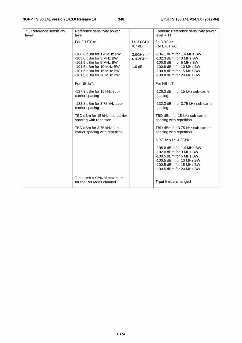
ETSI
ETSI TS 136 141 V14.3.0 (2017-04)3483GPP TS 36.141 version 14.3.0 Release 14
7.2 Reference sensitivity level
Reference sensitivity power level:
For E-UTRA:
-106.8 dBm for 1.4 MHz BW -103.0 dBm for 3 MHz BW -101.5 dBm for 5 MHz BW -101.5 dBm for 10 MHz BW -101.5 dBm for 15 MHz BW -101.5 dBm for 20 MHz BW For NB-IoT:
-127.3 dBm for 15 kHz sub-carrier spacing
-133.3 dBm for 3.75 kHz sub-carrier spacing
TBD dBm for 15 kHz sub-carrier spacing with repetition
TBD dBm for 3.75 kHz sub-carrier spacing with repetition
T-put limit = 95% of maximum for the Ref Meas channel
f ≤ 3.0GHz 0.7 dB 3.0GHz < f ≤ 4.2GHz
1.0 dB
Formula: Reference sensitivity power level + TT
f ≤ 3.0GHz For E-UTRA:
-106.1 dBm for 1.4 MHz BW -102.3 dBm for 3 MHz BW -100.8 dBm for 5 MHz BW -100.8 dBm for 10 MHz BW -100.8 dBm for 15 MHz BW -100.8 dBm for 20 MHz BW For NB-IoT:
-126.3 dBm for 15 kHz sub-carrier spacing
-132.3 dBm for 3.75 kHz sub-carrier spacing
TBD dBm for 15 kHz sub-carrier spacing with repetition
TBD dBm for 3.75 kHz sub-carrier spacing with repetition
3.0GHz < f ≤ 4.2GHz
-105.8 dBm for 1.4 MHz BW -102.0 dBm for 3 MHz BW -100.5 dBm for 5 MHz BW -100.5 dBm for 10 MHz BW -100.5 dBm for 15 MHz BW -100.5 dBm for 20 MHz BW T-put limit unchanged

ETSI
ETSI TS 136 141 V14.3.0 (2017-04)3493GPP TS 36.141 version 14.3.0 Release 14
7.3 Dynamic range Wanted signal power for Wide Area BS:
For E-UTRA:
-76.3 dBm for 1.4 MHz BW -72.4 dBm for 3 MHz BW -70.2 dBm for 5 MHz BW -70.2 dBm for 10 MHz BW -70.2 dBm for 15 MHz BW -70.2 dBm for 20 MHz BW For NB-IoT:
-99.7 dBm for 15 kHz sub-carrier spacing
-105.6 dBm for 3.75 kHz sub-carrier spacing
Wanted signal power for Home BS: -31.8 dBm for 1.4 MHz BW -27.9 dBm for 3 MHz BW -25.7 dBm for 5 MHz BW -25.7 dBm for 10 MHz BW -25.7 dBm for 15 MHz BW -25.7 dBm for 20 MHz BW T-put limit = 95% of maximum for the Ref Meas channel
0.3 dB
Formula: Wanted signal power + TT
For E-UTRA -76.0 dBm for 1.4 MHz BW -72.1 dBm for 3 MHz BW -69.9 dBm for 5 MHz BW -69.9 dBm for 10 MHz BW -69.9 dBm for 15 MHz BW -69.9 dBm for 20 MHz BW For NB-IoT:
-99.4 dBm for 15 kHz sub-carrier spacing
-105.3 dBm for 3.75 kHz sub-carrier spacing
Interferer signal power unchanged T-put limit unchanged
7.4 In-channel selectivity Wanted signal power:
For E-UTRA:
-106.9 dBm for 1.4 MHz BW -102.1 dBm for 3 MHz BW -100.0 dBm for 5 MHz BW -98.5 dBm for 10 MHz BW -98.5 dBm for 15 MHz BW -98.5 dBm for 20 MHz BW For in-band NB-IoT:
-124.3 dBm for 15 kHz sub-carrier spacing
-130.2 dBm for 3.75 kHz sub-carrier spacing
T-put limit = 95% of maximum for the Ref Meas channel
f ≤ 3.0GHz 1.4 dB 3.0GHz < f ≤ 4.2GHz
1.8 dB
Formula: Wanted signal power + TT
f ≤ 3.0GHz For E-UTRA:
-105.5 dBm for 1.4 MHz BW -100.7 dBm for 3 MHz BW -98.6 dBm for 5 MHz BW -97.1 dBm for 10 MHz BW -97.1 dBm for 15 MHz BW -97.1 dBm for 20 MHz BW For in-band NB-IoT:
-122.9 dBm for 15 kHz sub-carrier spacing
-128.8 dBm for 3.75 kHz sub-carrier spacing
3.0GHz < f ≤ 4.2GHz
-105.1 dBm for 1.4 MHz BW -100.3 dBm for 3 MHz BW -98.2 dBm for 5 MHz BW -96.7 dBm for 10 MHz BW -96.7 dBm for 15 MHz BW -96.7 dBm for 20 MHz BW Interferer signal power unchanged T-put limit unchanged

ETSI
ETSI TS 136 141 V14.3.0 (2017-04)3503GPP TS 36.141 version 14.3.0 Release 14
7.5 Adjacent Channel Selectivity (ACS) and narrow-band blocking
Narrowband blocking: Wanted signal power For E-UTRA, all BWs: (PREFSENS + 6 dB) For in-band NB-IoT, 1.4 MHz and 3 MHz BW:
(PREFSENS + 11dB)
For in-band NB-IoT, 5 MHz BW:
(PREFSENS + 8dB)
For in-band NB-IoT, 10MHz, 15MHz and 20MHz BW:
(PREFSENS + 6dB)
For guard-band NB-IoT, 5 MHz BW:
(PREFSENS + 11dB)
For guard-band NB-IoT, 10MHz, 15MHz and 20MHz BW:
(PREFSENS + 6dB)
For standalone NB-IoT:
(PREFSENS + 12dB)
Interferer signal power, all BWs: -49dBm Adjacent channel selectivity: Wanted signal power For E-UTRA,1.4 MHz BW: (PREFSENS + 11dB) For E-UTRA,3 MHz BW: (PREFSENS + 8dB) For E-UTRA,5 MHz, 10MHz, 15MHz and 20MHz BW: (PREFSENS + 6dB) For in-band NB-IoT, 1.4 MHz BW:
(PREFSENS + 11dB)
For in-band NB-IoT, 3 MHz BW:
(PREFSENS + 8dB)
For in-band NB-IoT, 5 MHz, 10MHz, 15MHz and 20MHz BW:
(PREFSENS + 6dB)
For guard-band NB-IoT, 5 MHz BW:
(PREFSENS + 10dB)
For guard-band NB-IoT, 10 MHz BW:
(PREFSENS + 8dB)
0 dB Formula: Wanted signal power + TT Narrowband blocking: For E-UTRA, all BWs: ( PREFSENS + 6 dB) For in-band NB-IoT, 1.4 MHz and 3 MHz BW:
(PREFSENS + 11dB)
For in-band NB-IoT, 5 MHz BW:
(PREFSENS + 8dB)
For in-band NB-IoT, 10MHz, 15MHz and 20MHz BW:
(PREFSENS + 6dB)
For guard-band NB-IoT, 5 MHz BW:
(PREFSENS + 11dB)
For guard-band NB-IoT, 10MHz, 15MHz and 20MHz BW:
(PREFSENS + 6dB)
For standalone NB-IoT:
(PREFSENS + 12dB)
Interferer signal power unchanged Adjacent channel selectivity: Wanted signal power For E-UTRA,1.4 MHz BW: (PREFSENS + 11dB) For E-UTRA, 3 MHz BW: (PREFSENS + 8dB) For E-UTRA,5 MHz, 10MHz, 15MHz and 20MHz BW: (PREFSENS + 6dB) For in-band NB-IoT, 1.4 MHz BW:
(PREFSENS + 11dB)
For in-band NB-IoT, 3 MHz BW:
(PREFSENS + 8dB)
For in-band NB-IoT, 5 MHz, 10MHz, 15MHz and 20MHz BW:
(PREFSENS + 6dB)
For guard-band NB-IoT, 5 MHz BW:
(PREFSENS + 10dB)
For guard-band NB-IoT, 10 MHz BW:
(PREFSENS + 8dB)
For guard-band NB-IoT, 15MHz and 20MHz BW:
(PREFSENS + 6dB)

ETSI
ETSI TS 136 141 V14.3.0 (2017-04)3513GPP TS 36.141 version 14.3.0 Release 14
For guard-band NB-IoT, 15MHz and 20MHz BW:
(PREFSENS + 6dB)
For standalone NB-IoT:
(PREFSENS + 19.5dB)
Interferer signal power, all BWs: -52 dBm T-put limit = 95% of maximum for the Ref Meas channel
For standalone NB-IoT:
(PREFSENS + 19.5dB) Interferer signal power unchanged T-put limit unchanged
7.6.5.1 Blocking (General requirements)
In-band blocking
Wanted signal power, all BWs: (PREFSENS + 6 dB)
Interferer signal power, all BWs: -43dBm
Out of band blocking
Wanted signal power, all BWs: (PREFSENS + 6 dB)
Interferer signal power, all BWs: -15dBm CW
T-put limit = 95% of maximum for the Ref Meas channel
0 dB Formula: Wanted signal power + TT, all BWs: (PREFSENS + 6 dB) Interferer signal power unchanged T-put limit unchanged
7.6.5.2 Blocking (Co-location with other base stations)
Co-located blocking
Wanted signal power, all BWs: (PREFSENS + 6 dB)
Interferer signal power, all BWs: +16dBm
T-put limit = 95% of maximum for the Ref Meas channel
0 dB Formula: Wanted signal power + TT, all BWs: (PREFSENS + 6 dB)
Interferer signal power unchanged
T-put limit unchanged
7.7 Receiver spurious emissions
-57dBm / 100 kHz
-47dBm / 1 MHz
0dB Formula: Minimum Requirement + TT Emission requirements unchanged
7.8 Receiver intermodulation
Wanted signal power, all BWs: (PREFSENS + 6dB) CW Interferer power, all BWs: -52 dBm Modulated Interferer power:, all BWs: -52 dBm T-put limit = 95% of maximum for the Ref Meas channel
0 dB Formula: Wanted signal power + TT, all BWs: ( PREFSENS + 6dB) CW Interferer signal power unchanged Modulated Interferer signal power unchanged T-put limit unchanged

ETSI
ETSI TS 136 141 V14.3.0 (2017-04)3523GPP TS 36.141 version 14.3.0 Release 14
G.3 Measurement of Performance Requirements Table G.3-1: Derivation of Test Requirements (Performance tests)

ETSI
ETSI TS 136 141 V14.3.0 (2017-04)3533GPP TS 36.141 version 14.3.0 Release 14
Test Minimum Requirement in TS 36.104
Test Tolerance
(TT)
Test Requirement in TS 36.141
8.2.1 Performance requirements of PUSCH in multipath fading propagation conditions transmission on single antenna port
SNRs as specified 0.6dB Formula: SNR + TT T-put limit unchanged
8.2.1A Performance requirements of PUSCH in multipath fading propagation conditions transmission on two antenna ports
SNRs as specified 0.8dB Formula: SNR + TT T-put limit unchanged
8.2.2 Performance requirements for UL timing adjustment
SNRs as specified 0.6dB for fading cases 0.3dB for AWGN cases
Formula: SNR + TT T-put limit unchanged
8.2.3 Performance requirements for HARQ-ACK multiplexed on PUSCH
SNRs as specified 0.6dB Formula: SNR + TT False ACK limit unchanged Correct ACK limit unchanged
8.2.4 Performance requirements for High Speed Train conditions
SNRs as specified 0.3dB Formula: SNR + TT T-put limit unchanged
8.2.5 Performance requirements for PUSCH with TTI bundling and enhanced HARQ pattern
SNRs as specified 0.6dB Formula: SNR + TT Residual BLER limit unchanged
8.2.6 Enhanced performance requirements type A of PUSCH in multipath fading propagation conditions with synchronous interference
SINRs as specified 0.6dB Formula: SINR + TT T-put limit unchanged
8.2.6A Enhanced performance requirements type A of PUSCH in multipath fading propagation conditions with asynchronous interference
SINRs as specified 0.6dB Formula: SINR + TT T-put limit unchanged
8.2.7 Performance requirements of PUSCH in multipath fading propagation conditions transmission on single antenna port for supporting Cat-M1 UEs
SINRs as specified 0.6dB Formula: SINR + TT T-put limit unchanged
8.3.1 ACK missed detection for single user PUCCH format 1a transmission on single antenna port
SNRs as specified 0.6dB Formula: SNR + TT False ACK limit unchanged Correct ACK limit unchanged
8.3.2 CQI missed detection for PUCCH format 2 transmission on single antenna port
SNRs as specified 0.6dB Formula: SNR + TT False CQI limit unchanged Correct CQI limit unchanged
8.3.3 ACK missed detection for multi user PUCCH format 1a
SNRs as specified 0.6dB Formula: SNR + TT False ACK limit unchanged Correct ACK limit unchanged
8.3.4 ACK missed detection for PUCCH format 1b with Channel Selection
SNRs as specified 0.6 dB Formula: SNR + TT False ACK limit unchanged Correct ACK limit unchanged

ETSI
ETSI TS 136 141 V14.3.0 (2017-04)3543GPP TS 36.141 version 14.3.0 Release 14
8.3.5 ACK missed detection for PUCCH format 3
SNRs as specified 0.6 dB Formula: SNR + TT False ACK limit unchanged Correct ACK limit unchanged
8.3.6 NACK to ACK detection for PUCCH format 3
SNRs as specified 0.6 dB Formula: SNR + TT False ACK limit unchanged Correct NACK limit unchanged
8.3.7 ACK missed detection for PUCCH format 1a transmission on two antenna ports
SNRs as specified 0.8dB Formula: SNR + TT False ACK limit unchanged Correct ACK limit unchanged
8.3.8 CQI performance requirements for PUCCH format 2 transmission on two antenna ports
SNRs as specified 0.8dB Formula: SNR + TT False ACK limit unchanged Correct ACK limit unchanged
8.3.9 CQI missed detection for PUCCH format 2 with DTX detection
SNRs as specified 0.6 dB for one antenna port 0.8 dB for two antenna ports
Formula: SNR + TT False CQI limit unchanged Correct CQI limit unchanged
8.3.10 ACK missed detection for PUCCH format 1a transmission on single antenna port for supporting Cat-M1 UEs
SNRs as specified 0.6 dB Formula: SNR + TT False ACK limit unchanged Correct ACK limit unchanged
8.3.11 CQI performance requirements for PUCCH format 2 transmission on single antenna port for supporting Cat-M1 UEs
SNRs as specified 0.6 dB
Formula: SNR + TT False CQI limit unchanged Correct CQI limit unchanged
8.3.12 ACK missed detection for PUCCH format 4
SNRs as specified 0.6 dB Formula: SNR + TT False ACK limit unchanged Correct ACK limit unchanged
8.4.1 PRACH false alarm probability and missed detection
SNRs as specified 0.6dB for fading cases 0.3dB for AWGN cases
Formula: SNR + TT PRACH False detection limit unchanged PRACH detection limit unchanged
8.5.1 Performance requirements for NPUSCH format 1
SINRs as specified 0.6dB Formula: SINR + TT T-put limit unchanged
8.5.2 ACK missed detection for NPUSCH format 2
SINRs as specified 0.6dB Formula: SNR + TT False ACK limit unchanged Correct ACK limit unchanged
8.5.3 Performance requirements for NPRACH
SNRs as specified 0.6dB for fading cases 0.3dB for AWGN cases
Formula: SNR + TT NPRACH False detection limit unchanged NPRACH detection limit unchanged

ETSI
ETSI TS 136 141 V14.3.0 (2017-04)3553GPP TS 36.141 version 14.3.0 Release 14
Annex H (Informative): E-UTRAN Measurement Test Cases <Text will be added.>

ETSI
ETSI TS 136 141 V14.3.0 (2017-04)3563GPP TS 36.141 version 14.3.0 Release 14
Annex I (Informative): Measurement system set-up Example of measurement system set-ups are attached below as an informative annex.
I.1 Transmitter
I.1.1 Base station output power, output power dynamics, transmitted signal quality, Frequency error, EVM, DL RS power, Unwanted emissions
Measurement equipment
BS under TX test TX
Figure I.1-1: Measuring system Set-up for base station output power, output power dynamics, transmitted signal quality, Frequency error, EVM, DL RS power, Unwanted emissions
I.1.2 Transmitter intermodulation
BS Under
Tx test
RX/TX or
TX
Spectrum analyser
Signal Generator
for the E-UTRA
ATT1Modulated signal
Figure I.1-2: Measuring system Set-up for Transmitter intermodulation

ETSI
ETSI TS 136 141 V14.3.0 (2017-04)3573GPP TS 36.141 version 14.3.0 Release 14
I.1.3 Time alignment error
Diversit
y
timing BS under TX test
TX 1
TX 2
TX 3
TX 4 Termination
Termination
Figure I.1-3: Measuring system Set-up for Test of Time alignment error
I.1.4 Home BS output power for adjacent channel protection
Home BS
(DUT) Signal generator for co-channel interference
Signal generator for adjacent channel
DL signal ATT1
ATT2
HYB
2
1 D
Power meter
a*
b*
c*
* antenna ports - a (optional): DL measurement receiver connector - b: main antenna port (UL/DL) - c (optional): diversity antenna port
Figure I.1-4: Measuring system set-up for Home BS output power for adjacent channel protection
I.1.5 Home BS output power for co-channel E-UTRA protection
Home BS
(DUT)
Signal generator for co-channel interference
ATT
2
1 D
Power meter
a*
b*
c*
* antenna ports - a (optional): DL measurement receiver connector - b: main antenna port (UL/DL) - c (optional): diversity antenna port
Figure I.1-5: (Option 1) Measuring system set-up for Home BS output power for co-channel E-UTRA protection

ETSI
ETSI TS 136 141 V14.3.0 (2017-04)3583GPP TS 36.141 version 14.3.0 Release 14
Home BS
(DUT)
Signal generator for co-channel interference
ATT1
2
1
Power meter
a*
b*
c*
* antenna ports - a (optional): DL measurement receiver connector - b: main antenna port (UL/DL) - c (optional): diversity antenna port
Signal generator for MUE UL
Interference
ATT2
D
Figure I.1-6: (Option 2) Measuring system set-up for Home BS output power for co-channel E-UTRA protection
I.2 Receiver NOTE: No HARQ feedback is done for any receiver test in Annex I.2.
I.2.1 Reference sensitivity level
RF signal source
RF out
Termination (If needed)
BS under RX Test
RX1 or RX1/TX
RX2
Figure I.2-1: Measuring system Set-up for Base Station Reference sensitivity level Test

ETSI
ETSI TS 136 141 V14.3.0 (2017-04)3593GPP TS 36.141 version 14.3.0 Release 14
I.2.2 Dynamic range
Signal generator for the wanted signal
Signal generator for the AWGN interfering signal
Hybrid
BS under RX test RX1 RX2
Termination (if needed)
Figure I.2-2: Measuring system Set-up for Dynamic range
I.2.3 In-channel selectivity
Signal generator for the wanted signal and E-UTRA interfering signal
Hybrid
BS under RX test RX1 RX2
Termination (if needed)
Figure I.2-3: Measuring system Set-up for In-channel selectivity

ETSI
ETSI TS 136 141 V14.3.0 (2017-04)3603GPP TS 36.141 version 14.3.0 Release 14
I.2.4 Adjacent Channel Selectivity (ACS) and narrowband blocking
Figure I.2-4: Measuring system Set-up for Adjacent channel selectivity and narrowband blocking
I.2.5 Blocking characteristics
Signal Generator for for the wanted signal ATT1
Termination
Signal Generator for the interfering signal ATT2
Termination
HYBRID
BS under RX Test RX1/TX
RX2
Figure I.2-5: Measuring system Set-up for Blocking characteristics
I.2.6 Receiver spurious emission
BS under RX Test
Termination
Termination
TX notch Measurement
receiver
TX
RX1
RX2
Figure I.2-6: Measuring system Set-up for Receiver spurious emission
BS Under RX Test
RX1
RX2
HYBRID
ATT2
ATT1 Signal Generator for the wanted signal
Signal Generator for the interfering signal TERMINATION

ETSI
ETSI TS 136 141 V14.3.0 (2017-04)3613GPP TS 36.141 version 14.3.0 Release 14
I.2.7 Intermodulation characteristics
Figure I.2-7: Measuring system Set-up for intermodulation characteristics
I.3 Performance requirement
I.3.1 Performance requirements for PRACH in static conditions
RX A
RX B
Base Station
under test
BS tester
AWGN Generator
AWGN Generator
Figure I.3-1: Functional set-up for performance requirements for PRACH in static conditions for BS with Rx diversity (2 Rx case shown)
BS under
RX Test
RX1
RX2
HYBRID
ATT2
ATT1 Signal Generator
for the wanted
signal
Signal Generator
for the CW
interfering signal
TERMINATION
Signal Generator
for the E-UTRA
interfering signal ATT3
HYBRID

ETSI
ETSI TS 136 141 V14.3.0 (2017-04)3623GPP TS 36.141 version 14.3.0 Release 14
I.3.2 Performance requirements for PUSCH, PRACH, single user PUCCH in multipath fading conditions and for High Speed Train conditions
Figure I.3-2: Functional set-up for performance requirements for PUSCH, PRACH, single user PUCCH in multipath fading conditions and for High Speed Train conditions for BS with Rx diversity (2 Rx
case shown)
NOTE 1: For HST tests which are specified in static conditions, the Channel Simulators are assumed to simulate the Doppler shift.
NOTE 2: The HARQ Feedback could be done as an RF feedback or as a digital feedback. The HARQ Feedback should be error free.

ETSI
ETSI TS 136 141 V14.3.0 (2017-04)3633GPP TS 36.141 version 14.3.0 Release 14
I.3.3 Performance requirements for multi user PUCCH in multipath fading conditions
Figure I.3-3: Functional set-up for performance requirements for multi user PUCCH in multipath fading conditions
I.3.4 Performance requirement for UL timing adjustment
Figure I.3-4: Functional set-up for performance requirement for UL timing adjustment (Scenario 2 case shown)
NOTE 1: In case of UL timing adjustment Scenario 1, channel simulators needs to be used for fading and Doppler shift emulation.
NOTE 2: The HARQ feedback and TA commands could be done as an RF feedback or as a digital feedback. The HARQ feedback and TA commands should be error free.

ETSI
ETSI TS 136 141 V14.3.0 (2017-04)3643GPP TS 36.141 version 14.3.0 Release 14
I.3.5 Performance requirements for PUCCH transmission on two antenna ports in multipath fading conditions
BS Tester
TX A
TX B
BS Station Under test
RX A
RX B
AWGN Generator
AWGN Generator
Channel Simulator
Channel Simulator
Channel Simulator
Channel Simulator
Figure I.3-5: Functional set-up for performance requirements for PUCCH transmission on two antenna ports in multipath fading conditions (2 Rx case shown)
I.3.6 Performance requirements for PUSCH transmission on two antenna ports in multipath fading conditions
BS Tester
TX A
TX B
BS Station Under test
RX A
RX B
AWGN Generator
AWGN Generator
Channel Simulator
Channel Simulator
Channel Simulator
Channel Simulator
HARQ Feedback
Figure I.3-6: Functional set-up for performance requirements for PUSCH transmission on two antenna ports in multipath fading conditions (2 Rx case shown)

ETSI
ETSI TS 136 141 V14.3.0 (2017-04)3653GPP TS 36.141 version 14.3.0 Release 14
I.3.7 Enhanced performance requirements type A of PUSCH in multipath fading propagation conditions with synchronous or asynchronous interference
Figure I.3-7a: Functional set-up for enhanced performance requirements type A of 2Rx PUSCH in multipath fading conditions with synchronous interference (1 interferer and 2 Rx case shown)
BS tester
Wanted signal
Interferer 1
BS under test
Rx 1
Rx 2 ATT 2
Channel simulator
Channel simulator
AWGN geneartor
AWGN geneartor
ATT 1 Channel simulator
Channel simulator
HARQ Feedback

ETSI
ETSI TS 136 141 V14.3.0 (2017-04)3663GPP TS 36.141 version 14.3.0 Release 14
Figure I.3-7b: Functional set-up for enhanced performance requirements type A of PUSCH with 2Rx in multipath fading conditions with asynchronous interference (2 interferers and 2 Rx case shown)
AWGN geneartor
BS tester
Wanted signal
Interferer 1-1
Interferer 1-2
ATT 1
Channel simulator
Channel simulator AWGN
geneartor AWGN geneartor
BS under test
Rx 1
Rx 2
ATT 2
Channel simulator
Channel simulator
ATT 3
Channel simulator
Channel simulator
HARQ Feedback

ETSI
ETSI TS 136 141 V14.3.0 (2017-04)3673GPP TS 36.141 version 14.3.0 Release 14
Figure I.3-7c: Functional set-up for enhanced performance requirements type A of 4Rx PUSCH in multipath fading conditions with synchronous or asynchronous interference (2 interferers and 4 Rx
case shown)
BS tester
Wanted signal
Interferer 1 (Interferer 1-1)
Interferer 2 (Interferer 1-2)
ATT 1
Channel simulator
Channel simulator
Channel simulator
Channel simulator
AWGN geneartor AWGN geneartor
AWGN geneartor AWGN geneartor
AWGN geneartor AWGN geneartor
AWGN geneartor AWGN geneartor
BS under test
Rx 1
Rx 2
Rx 3
Rx 4
ATT 2
Channel simulator
Channel simulator
Channel simulator
Channel simulator
ATT 3
Channel simulator
Channel simulator
Channel simulator
Channel simulator
HARQ Feedback

ETSI
ETSI TS 136 141 V14.3.0 (2017-04)3683GPP TS 36.141 version 14.3.0 Release 14
Figure I.3-7d: Functional set-up for enhanced performance requirements type A of 8Rx PUSCH in multipath fading conditions with synchronous or asynchronous interference (2 interferers and 8 Rx
case shown)
BS tester
Wanted signal
Interferer 1 (Interferer 1-1)
Interferer 2 (Interferer 1-2)
AWGN geneartor AWGN geneartor
AWGN geneartor AWGN geneartor
AWGN geneartor AWGN geneartor
AWGN geneartor AWGN geneartor
AWGN geneartor AWGN geneartor
AWGN geneartor AWGN geneartor
AWGN geneartor AWGN geneartor
AWGN geneartor AWGN geneartor
BS under test
Rx 1
Rx 2
Rx 3
Rx 4
Rx 5
Rx 6
Rx 7
Rx 8
ATT 1
Channel simulator
Channel simulator
Channel simulator
Channel simulator
Channel simulator
Channel simulator
Channel simulator
Channel simulator
ATT 2
Channel simulator
Channel simulator
Channel simulator
Channel simulator
Channel simulator
Channel simulator
Channel simulator
Channel simulator
ATT 3
Channel simulator
Channel simulator
Channel simulator
Channel simulator
Channel simulator
Channel simulator
Channel simulator
Channel simulator
HARQ Feedback

ETSI
ETSI TS 136 141 V14.3.0 (2017-04)3693GPP TS 36.141 version 14.3.0 Release 14
I.4 Channel access procedures
Figure I.4: Measuring system Set-up for Channel access procedures
BS under test
RX/TX
Signal
generator for
unlicensed
interferer
Attenuator
Measurement
equipment

ETSI
ETSI TS 136 141 V14.3.0 (2017-04)3703GPP TS 36.141 version 14.3.0 Release 14
Annex J (Informative): Unwanted emission requirements for multi-carrier BS
J.1 General In section 6.6, unwanted emission requirements for single carrier or multi-carrier BS are specified. This multi-carrier BS corresponds to a multi-carrier BS for E-UTRA, or a BS supporting intra-band contiguous CA. The following two pragmatic scenarios are considered in this annex:
- multi-carrier BS of different E-UTRA channel bandwidths, covering all scenarios except the channel bandwidth of the outermost carrier less than 5 MHz
- multi-carrier BS of E-UTRA and UTRA, covering all scenarios except the channel bandwidth of the outermost carrier less than 5 MHz.
All scenarios for channel bandwidths of the outermost carrier less than 5 MHz are for further study. Only multi-carrier BS with contiguous carriers are considered. The guidelines below assumes that the power spectral density of the multiple carriers is the same. All other combinations of multiple carriers are ffs.
Note 1: Further information and analysis for these scenarios can be found in TR 36.942 [14].
J.2 Multi-carrier BS of different E-UTRA channel bandwidths
For a multi-carrier E-UTRA BS transmitting a group of carriers of different channel bandwidths, the channel bandwidth of the outermost carriers (≥5 MHz) should be considered for ACLR and Operating band unwanted emission requirements. That is, the corresponding requirements for the channel bandwidth of each of the outermost carriers should be applied at the respective side of the group of transmitted carriers.
J.3 Multi-carrier BS of E-UTRA and UTRA For a multi-carrier BS transmitting a group of carriers of E-UTRA and UTRA, the RAT being used on the outermost carriers (≥5 MHz) should be considered for ACLR and Operating band unwanted emission requirements. That is, the corresponding requirements for the RAT being used on each of the outermost carriers should be applied at the respective side of the group of transmitted carriers.

ETSI
ETSI TS 136 141 V14.3.0 (2017-04)3713GPP TS 36.141 version 14.3.0 Release 14
Annex K (informative): Change history

ETSI
ETSI TS 136 141 V14.3.0 (2017-04)3723GPP TS 36.141 version 14.3.0 Release 14
Change history Date Meeting TDoc CR Rev Cat Subject/Comment New
version 2007-08 RAN4#44 R4-071503 TS skeleton created from 3GPP TS template. 0.0.1 2008-02 RAN4#46 R4-080004 Text proposals for section 2 to 4 (R4-072237) and
Annex A (R4-072048), which were agreed at RAN4#45, are incorporated.
0.1.0
2008-02 RAN4#46 R4-080446 Section for In-channel selectivity (new 7.4) is inserted and following sections are re-numbered. Editorial corrections are made in section 1, 3.2, 4,3, Table 4.3-1, 4.5.2.1, 4.6, 4.6.3, 4.6.4, 4.6.5 and A.2.
0.1.1
2008-02 RAN4#46 R4-080508 Text proposals in R4-080447, R4-080058, R4-080453, R4-080047, R4-080048, R4-080049, R4-080050, R4-080051, R4-080444, R4-080501, R4-080044, R4-080045 and R4-080046 are incorporated with modifications agreed in the first round discussion in RAN4#46 meeting. Overlapped parts in R4-080058 and R4-080044 for Annx A, R4-080444 and R4-080501 for section 8 are merged by the editor.
0.2.0
2008-03 RAN4#46bis
R4-080659 Editorial correction on section 8 is made: Text proposals for section 8 in R4-080444 are removed and the text proposal in R4-080501 is applied. Some editorial corrections are applied.
0.2.1
2008-04 RAN4#46bis
R4-080828 Text proposals agreed in R4-080583,R4-080617,R4-080663,R4-080664,R4-080606,R4-080584,,R4-080660,R4-080792,R4-080586,R4-080587,R4-080564,R4-080566 and R4-0806007 are incorporated with some editorial modifications.
0.3.0
2008-05 RAN4#47 R4-080844 Text proposals agreed in R4-080803,R4-0799,R4-0800,R4-080801 and R4-080826 are incorporated with editorial modifications.
0.4.0
2008-05 RAN4#47 R4-081198 Text proposals agreed in R4-081055, R4-081007, R4-081070, R4-081170, R4-080924, R4-080888, R4-081176, R4-080853, R4-080854, R4-080855, R4-081056, R4-080889 and R4-081178 are incorporated.
0.5.0
2008-05 RAN#40 RP-080381 Presented for information as V1.0.0. 1.0.0 2008-05 RAN#40 RP-080456 Editorial corrections on the formats in order to
comply with the drafting rule of 3GPP. 1.0.1
2008-06 RAN4#47bis
R4-081255 Correction in section 6.5.1.5, which was incorrectly proposed in R4-081226, is made. Editorial corrections on 6.5.3.4.1 and 8.4.1.4.2 are made.
1.0.2
2008-06 RAN4#47bis
R4-081256 Text proposals agreed in R4-081184 and R4-081187 are incorporated.
1.1.0
2008-06 RAN4#47bis
R4-081329 Editorial corrections in Table 8.4.1.5-2. 1.1.1
2008-08 RAN4#48 R4-081832 Text proposals agreed in the following documents are incorporated: R4-081377, R4-081547, R4-081282, R4-081284,R4-081652, R4-081502, R4-081283, R4-081650, R4-081268, R4-081269, R4-081270, R4-081653, R4-081272, R4-081645, R4-081481, R4-081281, R4-081322.
1.2.0
2008-08 RAN4#48 R4-082185 Text proposals agreed in the following documents are incorporated: R4-081832, R4-082087, R4-082093, R4-081847, R4-081965, R4-081967, R4-081944, R4-081709 , 4-082109, R4-081711, R4-081712, R4-082090, R4-081714, R4-081715, R4-081834, R4-082135, R4-082173, R4-082160, R4-082171
1.3.0
2008-09 RAN#41 RP-080715 Typo in Table 8.4.1.5-1 (section 8.4.1.5) , which was brought in at V1.1.0 when implementing R4-081187 is corrected.
2.0.0
2008-09 RAN#41 RP-080715 Presented for approval as V2.0.0 8.0.0 2008-12 RAN #42 RP-080915 10 Correction to the figure with the Transmision
Bandwidth configuration 8.1.0
2008-12 RAN #42 RP-080916 14 Modification to EARFCN 8.1.0 2008-12 RAN #42 RP-080919 3 Introduction of Band 17 8.1.0 2008-12 RAN #42 RP-080920 27 Update of total dynamic range limits 8.1.0 2008-12 RAN #42 RP-080921 28 Update of TDD-FDD coexistance requirements 8.1.0 2008-12 RAN #42 RP-080922 30 PRACH demodulation requirements update 8.1.0 2008-12 RAN #42 RP-090923 4 General corrections in section 7-Annexes 8.1.0 2008-12 RAN #42 RP-080923 12 General corrections in sections 4-6 8.1.0

ETSI
ETSI TS 136 141 V14.3.0 (2017-04)3733GPP TS 36.141 version 14.3.0 Release 14
2008-12 RAN #42 RP-080923 19 1 Corrections to references, definitions symbols and abbreviations
8.1.0
2008-12 RAN #42 RP-080923 20 1 Corrections to clause 4 and 5 8.1.0 2008-12 RAN #42 RP-080923 21 2 Correction to clause 6 8.1.0 2008-12 RAN #42 RP-080923 22 1 Correction to clause 7 8.1.0 2008-12 RAN #42 RP-080923 23 Correction to clause 8 8.1.0 2008-12 RAN #42 RP-080923 24 Correction to Annex G 8.1.0 2008-12 RAN #42 RP-080924 5 Correction of EVM test condition related to total
power dynamic range 8.1.0
2008-12 RAN #42 RP-080924 8 Addition of BS transmit ON/OFF power tests 8.1.0 2008-12 RAN #42 RP-080924 11 Clarificatiopn on emission requirements 8.1.0 2008-12 RAN #42 RP-080924 32 E-UTRA TDD test models 8.1.0 2008-12 RAN #42 RP-080924 17 Correction to transmitter intermodulation test 8.1.0 2008-12 RAN #42 RP-080924 26 Correction to E-UTRA test models 8.1.0 2008-12 RAN #42 RP-080925 25 EVM averaging for TDD in the global in channel TX
test 8.1.0
2008-12 RAN #42 RP-080926 1 1 eNB performance test requirement for UL timing adjustment
8.1.0
2008-12 RAN #42 RP-080926 2 1 eNB performance test requirement for PUCCH format 2
8.1.0
2008-12 RAN #42 RP-080926 13 1 eNB performance test requirements for Multi User PUCCH
8.1.0
2008-12 RAN #42 RP-080926 31 eNB performance requirements for HARQ ACK multiplexed on PUSCH
8.1.0
2008-12 RAN #42 RP-080927 9 eNB performance test requirements for High Speed Train conditions
8.1.0
2008-12 RAN #42 RP-080927 15 1 Clarification of eNB HST propagation conditions (36.141, rel-8)
8.1.0
2008-12 RAN #42 RP-080927 7 1 Correction of Doppler shift trajectories equations for HST conditions
8.1.0
2009-03 RAN #43 RP-090173 54 Clarification of EARFCN for 36.141 8.2.0 2009-03 RAN #43 RP-090175 55 1 Regional requirement on maximum rated power for
Band 34 8.2.0
2009-03 RAN #43 RP-090177 43 Clarification of the BS performance test w.r.t PUCCH ACK/NACK Repetition configuration
8.2.0
2009-03 RAN #43 RP-090177 48 PUSCH ACK/NAK simulation assumptions finalization for simulations with implementation margins
8.2.0
2009-03 RAN #43 RP-090177 53 HARQ-ACK multiplexed on PUSCH performance requirement results
8.2.0
2009-03 RAN #43 RP-090178 36 Correction of clause 4. 8.2.0 2009-03 RAN #43 RP-090178 39 Correction and update of Annex G. 8.2.0 2009-03 RAN #43 RP-090179 34 Corrections related to E-UTRA test models 8.2.0 2009-03 RAN #43 RP-090179 35 Correction of E-UTRAN TDD eNodeB test models 8.2.0 2009-03 RAN #43 RP-090179 37 Correction and update of clause 6. 8.2.0 2009-03 RAN #43 RP-090179 40 Clarification of PHS band including the future plan 8.2.0 2009-03 RAN #43 RP-090179 45 Correction to transmitter intermodulation test 8.2.0 2009-03 RAN #43 RP-090179 49 Unsynchronized TDD coexistence requirements 8.2.0 2009-03 RAN #43 RP-090179 51 Correction to unwanted emission limit for 3MHz(E-
UTRA bands < 1GHz) for Category A 8.2.0
2009-03 RAN #43 RP-090180 42 1 Correction to BS reciever test requirements 8.2.0 2009-03 RAN #43 RP-090180 56 eNB ACS frequency offset 8.2.0 2009-03 RAN #43 RP-090181 38 Correction of clause 8. 8.2.0 2009-03 RAN #43 RP-090181 41 Modifications on parameter settings for some
demodulation test cases. 8.2.0
2009-03 RAN #43 RP-090181 44 AWGN level for UL demodulation performance tests 8.2.0 2009-05 RAN #44 RP-090544 61 Clarification of requirements for multicarrier BS.
(Technically Endorsed CR in R4-50bis - R4-091445) 8.3.0
2009-05 RAN #44 RP-090545 62 Correction of test models for E-UTRAN. (Technically Endorsed CR in R4-50bis - R4-091461)
8.3.0
2009-05 RAN #44 RP-090545 66 Test system uncertainty for Transmitter intermodulation
8.3.0
2009-05 RAN #44 RP-090545 67 Adding test model for transmit ON/OFF test 8.3.0 2009-05 RAN #44 RP-090545 68 Correction to DL RS power 8.3.0 2009-05 RAN #44 RP-090545 64r1 Addition of missing Test Tolerances for transmitter
tests 8.3.0
2009-05 RAN #44 RP-090545 70 Test system uncertainty for Receiver dynamic range 8.3.0 2009-05 RAN #44 RP-090545 58 CR 36.141 ACS frequency offset. (Technically
Endorsed CR in R4-50bis - R4-091330) 8.3.0
2009-05 RAN #44 RP-090545 63r2 Test Tolerances for Performance test cases 8.3.0 2009-05 RAN #44 RP-090545 59 UL timing adjustment measurement system set-up.
(Technically Endorsed CR in R4-50bis - R4-091414) 8.3.0

ETSI
ETSI TS 136 141 V14.3.0 (2017-04)3743GPP TS 36.141 version 14.3.0 Release 14
2009-05 RAN #44 RP-090545 60 UL timing adjustment performance requirement clarifications. (Technically Endorsed CR in R4-50bis - R4-091438)
8.3.0
2009-05 RAN #44 RP-090559 57 Introduction of Extended LTE800 requirements. (Technically Endorsed CR in R4-50bis - R4-091064)
9.0.0
2009-09 RAN #45 RP-090833
072
Clarification of the multi user PUCCH performance determintion (R43-51Cat F Endorsed CR in: R4-092227)
9.1.0
2009-09 RAN #45 RP-090833
074
Clarification of the UL timing adjustment performance determination (R43-51Cat F Endorsed CR in: R4-092229)
9.1.0
2009-09 RAN #45 RP-090833 076 Receiver intermodulation clarification 9.1.0 2009-09 RAN #45 RP-090833 078 Corrections to E-UTRA Rx requirements 9.1.0 2009-09 RAN #45 RP-090826
079
Correction of spurious emission requirements for LTE800
9.1.0
2009-09 RAN #45 RP-090833 081
Clarifications on testing UL timing adjustment requirements
9.1.0
2009-09 RAN #45 RP-090833 083 Correction on reference of extreme power supply 9.1.0 2009-09 RAN #45 RP-090833 092 LTE operating band unwanted emissions revision 9.1.0 2009-12
RP-46 RP-091286 095
Introduction of Extended LTE1500 requirements for TS36.141 (Technically endorsed at RAN 4 52bis in R4-093637) 9.2.0
2009-12 RP-46 RP-091267 098
Clarification of the test method for blocking (Technically endorsed at RAN 4 52bis in R4-093769) 9.2.0
2009-12 RP-46 RP-091267 100
Adding missing EARFCN for band 33 and 34 (Technically endorsed at RAN 4 52bis in R4-093770) 9.2.0
2009-12 RP-46 RP-091267 102
Incorrect FRC A3-2 Coded block size (Technically endorsed at RAN 4 52bis in R4-093771) 9.2.0
2009-12 RP-46 RP-091266 104
LTE operating band unwanted emissions correction (Technically endorsed at RAN 4 52bis in R4-093802) 9.2.0
2009-12 RP-46 RP-091267 106
HARQ feedback clarification addition (Annex B) (Technically endorsed at RAN 4 52bis in R4-093997) 9.2.0
2009-12
RP-46 RP-091266 108
Clarification on Spurious emissions limits for BS co-existed with another BS (Technically endorsed at RAN 4 52bis in R4-094012) 9.2.0
2009-12 RP-46 RP-091265 109
Corrections to ICS requirement (Technically endorsed at RAN 4 52bis in R4-093640) 9.2.0
2009-12 RP-46 RP-091270 111 1 Clarification on PRACH False alarm probability 9.2.0 2009-12 RP-46 RP-091295 112 1 E-UTRA BS classification 9.2.0 2009-12 RP-46 RP-091295 113 1 Home eNode B maximum output power 9.2.0 2009-12 RP-46 RP-091295 114 1 Home eNode B in-channel selectivity requirement 9.2.0 2009-12 RP-46 RP-091295 115 1 Home eNode B receiver intermodulation requirement 9.2.0 2009-12 RP-46 RP-091269 117 1 UL Timing Adjustment test clarifications 9.2.0 2009-12
RP-46 RP-091266 119 Multi-path fading propagation conditions reference correction 9.2.0
2009-12 RP-46 RP-091265 121
Corrections on frequency range of unwanted emissions requirements 9.2.0
2009-12 RP-46 RP-091266 122 1 Correction to the transmitter intermodulation 9.2.0 2009-12
RP-46 RP-091276 124 Testing in case of Rx diversity, Tx diversity and MIMO 9.2.0
2009-12 RP-46 RP-091295 130 1 Home eNode B ACLR requirement 9.2.0 2009-12
RP-46 RP-091295 131 1 Home eNode B ACS and narrow band blocking requirement 9.2.0
2009-12 RP-46 RP-091295 132 1 Home eNode B Blocking requirement 9.2.0 2009-12 RP-46 RP-091294 133 1 Home eNode B dynamic range requirement 9.2.0 2009-12 RP-46 RP-091294 134 1 Home eNode B frequency error requirement 9.2.0 2009-12 RP-46 RP-091294 135 2 Home eNode B performance requirement 9.2.0 2009-12
RP-46 RP-091294 136 1 Home eNode B operating band unwanted emissions requirement 9.2.0
2009-12 RP-46 RP-091294 137 1
Home eNode B reference sensitivity level requirement 9.2.0
2009-12 RP-46 RP-091294 138 2 Home eNode B spurious emission requirement 9.2.0 2009-12 RP-46 RP-091284 140 2 Inclusion of Band 20 BS Test parameters 9.2.0 2009-12
RP-46 RP-091267 144 1 Applicability of uncertainty for transmitter transient period 9.2.0
2010-03 RP-47 RP-100252 174 Correction of the frequency range for unwanted emmissions limits (cat-B/option 2/BW 3MHz)
9.3.0
2010-03 RP-47 RP-100252 171 Correction of Band 4 and 10 co-existence requirement
9.3.0
2010-03 RP-47 RP-100275 148 Dynamic range requirement for Local Area BS 9.3.0 2010-03 RP-47 RP-100275 149 In-channel selectivity for Local Area BS 9.3.0 2010-03 RP-47 RP-100275 150 ACS and narrow band blocking for Local Area BS 9.3.0

ETSI
ETSI TS 136 141 V14.3.0 (2017-04)3753GPP TS 36.141 version 14.3.0 Release 14
2010-03 RP-47 RP-100275 151 Receiver intermodulation for Local Area BS 9.3.0 2010-03 RP-47 RP-100275 152 Performance requirement for Local Area BS 9.3.0 2010-03 RP-47 RP-100275 153 E-UTRA BS classification 9.3.0 2010-03 RP-47 RP-100275 154 Maximum output power for Pico NodeB 9.3.0 2010-03 RP-47 RP-100275 155 Frequency error requirement for Pico NodeB 9.3.0 2010-03 RP-47 RP-100275 156 Reference sensitivity level requirement for Pico
NodeB 9.3.0
2010-03 RP-47 RP-100275 158 ACLR requirement for Pico NodeB 9.3.0 2010-03 RP-47 RP-100275 159 Operating band unwanted emissions requirement for
Pico NodeB 9.3.0
2010-03 RP-47 RP-100275 147 1 Spurious emissions requirement for Local Area BS 9.3.0 2010-03 RP-47 RP-100275 157 2 Blocking requirement for Pico NodeB 9.3.0 2010-03 RP-47 RP-100263 172 Correction of DTT protection requirement 9.3.0 2010-03 RP-47 RP-100266 161 Operating band unwanted emissions requirement for
Home eNodeB 9.3.0
2010-03 RP-47 RP-100266 160 1 Dynamic range requirement for Home eNodeB 9.3.0 2010-03 RP-47 RP-100266 162 Corrections of additional spurious emissions and
blocking requirements for HeNB 9.3.0
2010-03 RP-47 RP-100266 166 Home BS Output Power Conformance Testing for Adjacent Channel Protection
9.3.0
2010-03 RP-47 RP-100274 175 Requirements for HARQ-ACK multiplexed on PUSCH for E-UTRA LA and Home BS
9.3.0
2010-03 RP-47 RP-100274 176 CQI missed detection requirements for PUCCH format 2 for E-UTRA LA and Home BS
9.3.0
2010-03 RP-47 RP-100274 165 1 Corrections to the receiver intermodulation requirements
9.3.0
2010-06 RP-48 RP-100621 180 Clarification on narrowband blocking requirements 9.4.0 2010-06 RP-48 RP-100621
178 Spurious emissions limits and blocking requirements for coexistence with CDMA850
9.4.0
2010-06 RP-48 RP-100621 183 1
Correction to the FRC for PUSCH 1.4M requirements
9.4.0
2010-06 RP-48 RP-100625 191 1
Clarification of applicability of requirements for multi-carrier BS
9.4.0
2010-06 RP-48 RP-100631 186
Co-existence with services in adjacent frequency bands
9.4.0
2010-09 RP-49 RP-100916 193 Clarifications on Base Station transmit and receive configurations
9.5.0
2010-09 RP-49 RP-100920 196 UL Timing Adjustment: Stationary UE propagation channel clarification
9.5.0
2010-09 RP-49 RP-100917 198 1 Modification on testing of time mask of E-UTRA TDD base station in R9
9.5.0
2010-09 RP-49 RP-100916 207 Adding operating unwanted emissions test to tests applicable to Ancillary RF Amplifiers
9.5.0
2010-09 RP-49 RP-100928 194 CR LTE_TDD_2600_US spectrum band definition additions to TS 36.141
10.0.0
2010-12 RP-50 RP-101327 224 Band 12 channel arrangement correction on 36.141 10.1.0 2010-12 RP-50 RP-101328 217 PUCCH format 2 performance requirements
definition clarification 10.1.0
2010-12 RP-50 RP-101328 236 Correction on multi user PUCCH test 10.1.0 2010-12 RP-50 RP-101342 213 Equaliser coefficient derivation for Global In-Channel
TX-Test 10.1.0
2010-12 RP-50 RP-101342 221 Correction of applicability of requirements 10.1.0 2010-12 RP-50 RP-101356 211 3 CR UMTS/LTE-3500 TDD spectrum band definition
additions for BS to TS 36.141 10.1.0
2010-12 RP-50 RP-101362 209 3 Introduction of L-band in TS36.141 10.1.0 2011-04 RP-51 RP-110336 241 - Receiver spurious emissions reference correction 10.2.0 2011-04 RP-51 RP-110337 247 2 Power off test tolerance 10.2.0 2011-04 RP-51 RP-110352 248 1 TS 36.141 subclause 6.5.4: DL RS Power 10.2.0 2011-04 RP-51 RP-110352 251 1 Correction of the test port description for TS 36.141
Rel-10 10.2.0
2011-04 RP-51 RP-110357 253 2 Band 42 and 43 co-existence for UMTS/LTE 3500 (TDD) for TS 36.141
10.2.0
2011-04 RP-51 RP-110344 255 - Operating band unwanted emissions for Band 1, 33 and 34 (TS 36.141)
10.2.0
2011-06 RP-52 RP-110794 261 Modifications to Band 3 to allow LTE Band 3 operation in Japan (Rel-10 TS36.141 CR)
10.3.0
2011-06 RP-52 RP-110807 262 Carrier Aggregation for LTE in TS 36.141 / general requirements
10.3.0
2011-06 RP-52 RP-110807 264 Carrier Aggregation for LTE in TS 36.141 / receiver requirements
10.3.0
2011-06 RP-52 RP-110802 266 Co-existence/co-location between Band 42 and 43 in TS 36.141
10.3.0

ETSI
ETSI TS 136 141 V14.3.0 (2017-04)3763GPP TS 36.141 version 14.3.0 Release 14
2011-06 RP-52 RP-110796 267 Harmonization of co-existence between Home BS and WA BS in 36.141
10.3.0
2011-06 RP-52 RP-110804 258 1 Expanded 1900 MHz addition to 36.141 10.3.0 2011-06 RP-52 RP-110807 263 1 Carrier Aggregation for LTE in TS 36.141 /
transmitter requirements 10.3.0
2011-06 RP-52 RP-110813 265 1 Add 2GHz S-Band (Band 23) in 36.141 10.3.0 2011-06 RP-52 RP-110795 273 1 Fixing the misalignment of Band 24 GPS
Coexistence specifications between 36.104 and 36.141
10.3.0
2011-09 RP-53 RP-111252 290 Band 3/III operation in Japan 10.4.0 2011-09 RP-53 RP-111255 287 Uncertainties and Test Tolerances for 3000MHz to
4200MHz 10.4.0
2011-09 RP-53 RP-111255 292 1 Band 42 and 43 for LTE 3500 (TDD) correction to TS 36.141
10.4.0
2011-09 RP-53 RP-111255 293 1 Add Band 22/XXII for LTE/UMTS 3500 (FDD) to TS 36.141
10.4.0
2011-09 RP-53 RP-111260 277 1 Test tolerance for UL-MIMO performance test cases 10.4.0 2011-09 RP-53 RP-111260 278 2 Performance requirements for UL-MIMO 10.4.0 2011-09 RP-53 RP-111262 282 Specifying acceptable uncertainty of OBW test in CA 10.4.0 2011-09 RP-53 RP-111262 285 1 CR to TS 36.141 Test requirements of Operating
Band Unwanted Emissions 10.4.0
2011-09 RP-53 RP-111262 286 2 Correction for TS 36.141 10.4.0 2011-09 RP-53 RP-111262 291 Co-existence and co-location corrections in 36.141 10.4.0 2011-09 RP-53 RP-111266 268 3 TS36.141 CR: on PUSCH tests 10.4.0 2011-09 RP-53 RP-111266 283 CA PUCCH performance requirements for 36.141 10.4.0 2011-12 RP-54
RP-111684 295 Corrections of CA uplink performance test cases in TS36.141 10.5.0
2011-12 RP-54 RP-111691 296
CA PUCCH performance requirements with test tolerance updates for 36.141 10.5.0
2011-12 RP-54 RP-111734 297
Clarification of general blocking requirements for co-existence in TS 36.141 10.5.0
2011-12 RP-54 RP-111693 298
Home BS Output Power for co-channel E-UTRA protection for 36.141 10.5.0
2011-12 RP-54 RP-111693 300
Update on Home BS Output Power for co-channel E-UTRA protection for 36.141 10.5.0
2011-12 RP-54 RP-111735 301 Corrections to 3500 MHz 10.5.0 2011-12 RP-54 RP-111686 302 1 TS36.141 CR: on Multi-Antenna channel models 10.5.0 2011-12 RP-54
RP-111690 303 Test procedure clarification for ACK false detection of multi-user PUCCH format 1a 10.5.0
2011-12 RP-54 RP-111687 304 3 TX ON or OFF CR 36.141 10.5.0 2011-12 RP-54
RP-111733 305 Correction of frequency range for spurious emission requirements 10.5.0
2012-03 RP-55 RP-120303 309 1
Clarification on test procedure for BS In-channel selectivity test 10.6.0
2012-03 RP-55 RP-120304 311 1 Definition of synchronized operation 10.6.0 2012-03 RP-55
RP-120295 312 1 Finalizing Home BS Output Power parameters for co-channel E-UTRA protection in 36.141 10.6.0
2012-03 RP-55 RP-120298 314 1 Addition of Band 23 HeNB specifications in 36.141 10.6.0 2012-03 RP-55 RP-120310 306 TS36.141 change for B41 CA 11.0.0 2012-03 RP-55 RP-120305 316 Introduction of Band 26/XXVI to TS 36.141 11.0.0 2012-06 RP-56
RP-120788 319 2 Introduction of intra-band non-contiguous operation
in TS 36.141 11.1.0 2012-06 RP-56
RP-120773 320 Introduction of CA band combination Band1 +
Band19 to TS 36.104 11.1.0
2012-06 RP-56 RP-120770 323 Editorial corrections in Home BS output power tests 11.1.0 2012-06 RP-56 RP-120780 325 1 Editorial corrections in TS 36.141 11.1.0 2012-06 RP-56
RP-120788 330 Introduction of time alignment error test requirement
for intra-band non-contiguous carrier aggregation 11.1.0
2012-06 RP-56 RP-120793 331 Introduction of APAC700(FDD) into TS 36.141 11.1.0 2012-06 RP-56
RP-120795 335 Editorial correction of the TDD eNB test model
configuration in TS 36.141 11.1.0
2012-06 RP-56 RP-120793 336 Introduction of Band 44 11.1.0 2012-06 RP-56 RP-120782 337 Time alignment error headline 11.1.0 2012-06 RP-56 RP-120783 338 1 Time alignment procedure in TS 36.141 11.1.0 2012-06 RP-56
RP-120773 341 Introduction of CA band combination Band4 +
Band13 to TS 36.141 11.1.0
2012-06 RP-56 RP-120773
342 Introduction of CA band combination Band4 + Band17 to TS 36.141
11.1.0
2012-06 RP-56 RP-120792 343 3 Introduction of E850_LB (Band 27) to TS 36.141 11.1.0 2012-06 RP-56
RP-120764 348 Correction of PHS protection requirements for TS
36.141 11.1.0
2012-09 RP-57 RP-121305
350 Clarification of inter-band CA test configuration generation
11.2.0

ETSI
ETSI TS 136 141 V14.3.0 (2017-04)3773GPP TS 36.141 version 14.3.0 Release 14
2012-09 RP-57 RP-121328 351 Introduction of CA band combination Band2 + Band17 to TS 36.141
11.2.0
2012-09 RP-57 RP-121321 352 Correction to intra-band non-contiguous carrier aggregation bands acronym
11.2.0
2012-09 RP-57 RP-121336 353 Introduction of CA band combination Band1 + Band21 to TS 36.141
11.2.0
2012-09 RP-57 RP-121327 354 Introduction of CA_B7_B20 in 36.141 11.2.0 2012-09 RP-57 RP-121301 357 Introduction of Japanese regulatory requirements for
LTE band 8 in 36.141 R11 11.2.0
2012-09 RP-57 RP-121334 359 1 Add requirements for inter-band CA of B_1-18 in TS36.141
11.2.0
2012-09 RP-57 RP-121339 360 1 TS 36.141 CR for CA_7 11.2.0 2012-09 RP-57 RP-121308 361 2 Reusing band 41 requirements for the Japan 2.5G
TDD band 11.2.0
2012-09 RP-57 RP-121330 362 1 Introduction of CA band combination Band3 + Band5 to TS 36.141
11.2.0
2012-09 RP-57 RP-121322 363 1 Intra-band non-contiguous CA BS receiver requirement
11.2.0
2012-09 RP-57 RP-121300 369 Modificaitions of frequency ranges on spurious emission requirements for Band 6, 18, 19
11.2.0
2012-09
RP-57 RP-121332 370 Introduction of CA band combination Band3 + Band20 to TS 36.141
11.2.0
2012-09 RP-57 RP-121332 372 Introduction of CA band combination Band8 + Band20 to TS 36.104
11.2.0
2012-09 RP-57 RP-121324 373 Introduction of CA_B3_B7 in 36.141 11.2.0 2012-12 RP-58 RP-121885 374 Introduction of CA band combination Band3 + Band8
to TS 36.141 11.3.0
2012-12 RP-58 RP-121891 375 Introduction of CA band combination Band4 + Band5 to TS 36.141
11.3.0
2012-12 RP-58 RP-121897 376 Introduction of CA band combination Band5 + Band17 to TS 36.141
11.3.0
2012-12 RP-58 RP-121855 381 Modification of ouput power requirement for LA E-UTRA BS
11.3.0
2012-12 RP-58 RP-121911 384 1 Modification on E-UTRA BS transmitter requriements
11.3.0
2012-12 RP-58 RP-121867 385 Clean up of specification R11 11.3.0 2012-12 RP-58 RP-121867 388 Cleanup of 36.141 performance 11.3.0 2012-12 RP-58 RP-121900 389 Implementing NC CA in all LTE Power Classes 11.3.0 2012-12 RP-58 RP-121895 390 Introduction of CA_B5_B12 in 36.141 11.3.0 2012-12 RP-58 RP-121911 391 Correcting missing figure and subclause
numbering in TS 36.141 11.3.0
2012-12 RP-58 RP-121900 393 Correction to intra-band non-contiguous carrier aggregation bands acronym
11.3.0
2012-12 RP-58 RP-121853 395 CR to add the rated ouput power for 8 Tx antennas
11.3.0
2012-12 RP-58 RP-121867 398 Correction to test requirements of operating band unwanted emissions
11.3.0
2012-12 RP-58 RP-121900 400 Further corrections for NC CA in LTE LA BS 11.3.0 2012-12 RP-58 RP-121907 401 1 CR for TS 36.141 transmitter characteristics
(Clause 6) due to introduction of Medium Range BS
11.3.0
2012-12 RP-58 RP-121888 402 Introduction of inter-band CA_4-12 into TS 36.141
11.3.0
2012-12 RP-58 RP-121883 403 Introduction of inter-band CA_11-18 into TS 36.141
11.3.0
2012-12 RP-58 RP-121907 404 Introduction of new BS classes to E-UTRA test specification (performance part)
11.3.0
2012-12 RP-58 RP-121907 405 1 E-UTRA MR BS receiver requirement 11.3.0 2012-12 RP-58 RP-121907 407 Introduction of medium range BS class to TS
36.141 (clause 1-5) 11.3.0
2012-12 RP-58 RP-121911 408 Allowing two antenna ports configuration in TAE test procedure for MIMO and Tx diversity
11.3.0
2012-12 RP-58 RP-121911 410 Replace TBD with final requirements for PUCCH format 2 with DTX detection
11.3.0
2012-12 RP-58 RP-121863 412 Removal of brackets around medium correlation in table B.5.2-1
11.3.0
2012-12 RP-58 RP-121911 413 Clarification of Doppler shift for moving propagation conditions test
11.3.0
2012-12 RP-58 RP-121867 415 Clarification of BS RF channels to be tested for ACLR
11.3.0

ETSI
ETSI TS 136 141 V14.3.0 (2017-04)3783GPP TS 36.141 version 14.3.0 Release 14
2012-12 RP-58 RP-121911 416 1 Correction of BS test configuration table 11.3.0 2012-12 RP-58 RP-121893 417 Introduction of inter-band CA_4-7 into TS
36.141 11.3.0
2012-12 RP-58 RP-121902 418 Introduction of Band 29 11.3.0 2013-03 RP-59 RP-130306 0334 1 TS 36.141 CR for CA_38 11.4.0 2013-03 RP-59 RP-130366 0388 2 Cleanup of 36.141 performance. 11.4.0 2013-03 RP-59 RP-130266 421 Correction of BS performance conformance tests 11.4.0 2013-03 RP-59 RP-130274 424 1 Correction of UEM requirements in TS 36.141 11.4.0 2013-03 RP-59 RP-130274 425 Correction to MSR BS classes conformance test
requirements 11.4.0
2013-03 RP-59 RP-130274 426 Correction to LTE BS classes performance requirements
11.4.0
2013-03 RP-59 RP-130284 428 1 Alignment of terminology for intra-band non-contiguous CA requirement
11.4.0
2013-03 RP-59 RP-130268 430 Correction to test requirements for PUSCH with 20 MHz channel bandwidth
11.4.0
2013-03 RP-59 RP-130287 431 Band 41 requirements for operation in Japan 11.4.0 2013-03 RP-59 RP-130284 432 1 Further corrections for non-contiguous spectrum
operation in TS36.141 11.4.0
2013-06 RP-60 RP-130769 433 Add the receiver requirements test procedure for Medium Range BS in TS36.141
11.5.0
2013-06 RP-60 RP-130770 434 Clarifications on transmitter spurious emission test in TS36.141
11.5.0
2013-06 RP-60 RP-130770 435 Further correct some mistakes for non-contiguous spectrum operation in TS36.141
11.5.0
2013-06 RP-60 RP-130766 441 CR on TAE for inter-band CA 11.5.0 2013-06 RP-60 RP-130767 442 1 Editorial correction of inter band CA table to TS
36.141 11.5.0
2013-06 RP-60 RP-130770 443 Addidtion of Bands for intra-band non-contiguous CA for 36.141
11.5.0
2013-06 RP-60 RP-130770 444 Clarification on non-contiguous spectrum operation test configuration
11.5.0
2013-06 RP-60 RP-130769 446 Modification on co-location spurious emission requirement for Medium Range BS
11.5.0
2013-06 RP-60 RP-130769 447 1 Modification on co-location blocking requirement for E-UTRA Medium Range BS
11.5.0
2013-06 RP-60 RP-130765 454 CR for UL-MIMO conformance test 11.5.0 2013-06 RP-60 RP-130772 419 1 Introduction of CA 1+8 into TS36.141(Rel-12) 12.0.0 2013-06 RP-60 RP-130782 427 1 Introduction of LTE Advanced inter-band Carrier
Aggregation of Band 3 and Band 28 to TS 36.141 12.0.0
2013-06 RP-60 RP-130786 436 Introduction of LTE Advanced inter-band Carrier Aggregation of Band 23 and Band 29 to TS 36.141
12.0.0
2013-06 RP-60 RP-130780 437 Introduction of LTE Advanced inter-band carrier aggregation of Band 3 and Band 26 into TS36.141 (Rel-12)
12.0.0
2013-06 RP-60 RP-130778 438 Introduction of CA band combination Band3 + Band19 to TS 36.141
12.0.0
2013-06 RP-60 RP-130784 439 Introduction of CA band combination Band19 + Band21 to TS 36.141
12.0.0
2013-06 RP-60 RP-130789 445 CR for 36.141 : Adding B25 non-contiguous intraband CA
12.0.0
2013-06 RP-60 RP-130774 448 Introduction of inter-band CA combination for Band 2 and Band 4
12.0.0
2013-06 RP-60 RP-130788 449 Introduction of intra-band non-contiguous CA combination for Band 4
12.0.0
2013-06 RP-60 RP-130792 450 1 Introduction of US WCS Band (Band 30) to TS 36.141
12.0.0
2013-06 RP-60 RP-130790 451 Introduction of LTE 450 in Brazil into TS 36.141 12.0.0 2013-06 RP-60 RP-130776 452 1 Introduction of LTE Advanced Inter-Band Carrier
Aggregation of Band 2 and Band 13 to TS36.141 12.0.0
09-2013 RP-61 RP-131301 455 36.141 CR for LTE_CA_C_B3 12.1.0 09-2013 RP-61 RP-131296 458 Add requirements for inter-band CA_1-26 into
TS36.141 12.1.0
09-2013 RP-61 RP-131299 461 Introduction of inter-band CA Band 2+5 12.1.0 09-2013 RP-61 RP-131280 465 Add the Receiver Blocking test procedure for Home
BS to TS36.141 12.1.0
12-2013 RP-62 RP-131960 466 Introduction of intra-band contiguous CA for Band 27 12.2.0 12-2013 RP-62 RP-131966 467 Introduction of LTE-Advanced intra-band non-
contiguous Carrier Aggregation in Band 23 to TS 36.141
12.2.0
12-2013 RP-62 RP-131947 472 Introduction of CA band combination Band2 + Band12 to TS 36.141
12.2.0

ETSI
ETSI TS 136 141 V14.3.0 (2017-04)3793GPP TS 36.141 version 14.3.0 Release 14
12-2013 RP-62 RP-131955 473 Introduction of CA band combination Band12 + Band25 to TS 36.141
12.2.0
12-2013 RP-62 RP-131945 475 2 CR 36.141: 1Tx 8Rx PUSCH conformance testing requirements
12.2.0
12-2013 RP-62 RP-131945 476 1 CR 36.141: 2Tx 8Rx PUCCH format 1a conformance testing requirements
12.2.0
12-2013 RP-62 RP-131945 477 2 CR on 1x8 PUCCH f1b, f3 comformance test 12.2.0 12-2013 RP-62 RP-131945 480 2 Introduction of 2x8 PUSCH test requirements for
LTE 8Rx UL 12.2.0
12-2013 RP-62 RP-131945 481 3 CR 36.141: 1Tx 8Rx PRACH conformance testing requirements
12.2.0
12-2013 RP-62 RP-131926 482 Editorial correction for the UL-MIMO channel model 12.2.0 12-2013 RP-62 RP-131945 483 1 CR for conformance test of PUCCH format 1a with
1Tx8Rx 12.2.0
12-2013 RP-62 RP-131945 485 Introduction of UL 8Rx channel correlation matrices 12.2.0 12-2013 RP-62 RP-131939 487 Correction to PUSCH test requirement 12.2.0 12-2013 RP-62 RP-131958 488 Introduction of LTE-Advanced intra-band contiguous
Carrier Aggregation in Band 23 to TS 36.141 12.2.0
12-2013 RP-62 RP-131962 489 Introduction of Intra-band non-contiguous CA in band 3 to TS 36.141
12.2.0
12-2013 RP-62 RP-131951 495 Introduction of CA band combination Band5 + Band25 to TS 36.141
12.2.0
12-2013 RP-62 RP-131949 498 Introduction of CA band combination B5 + B7 to TS 36.141
12.2.0
12-2013 RP-62 RP-131953 500 Introduction of CA band combination B7 + B28 to TS 36.141
12.2.0
12-2013 RP-62 RP-131931 502 Consideration on CA OBW requirement 12.2.0 12-2013 RP-62 RP-131964 505 Introduction of Intra-band non-contiguous CA in
band 7 to TS 36.141 12.2.0
12-2013 RP-62 RP-131930 508 Clarification for CACLR in TS36.141 12.2.0 12-2013 RP-62 RP-131967 509 Band 41 deployment in Japan 12.2.0 03-2014 RP-63 RP-140388 506 1 TS36.141 change for B39 CA 12.3.0 03-2014 RP-63 RP-140386 510 Introduction of CA band combination Band 3 and
Band 27 to TS 36.141 12.3.0
03-2014 RP-63 RP-140389 513 1 Corrections in TS 36.141 12.3.0 03-2014 RP-63 RP-140372 518 Introduction of multi-band BS testing to TS 36.141
(Clauses 1 - 5) 12.3.0
03-2014 RP-63 RP-140372 520 Introduction of test requirements for multi-band operation with conformance test improvement for multi-carrier testing (36.141, section 6 and 7)
12.3.0
03-2014 RP-63 RP-140375 523 Correction of abbreviations for negative acknowledgement
12.3.0
03-2014 RP-63 RP-140387 490 1 Introduction of CA band combination Band 39+Band 41 into BS specification
12.3.0
06-2014 RP-64 RP-140913 527 Multi-band corrections in 36.141 chapter 7 12.4.0 06-2014 RP-64 RP-140913 536 Corrections of multi-band BS testing to TS 36.141
(Clauses 1 - 5) 12.4.0
06-2014 RP-64 RP-140913 525 Multi-band corrections in 36.141 chapter 6 12.4.0 06-2014 RP-64 RP-140913 598 Correction on munufacturer's declaration in
TS36.141 12.4.0
06-2014 RP-64 RP-140913 567 Clarification on definitions and ACLR requirement in TS36.141
12.4.0
06-2014 RP-64 RP-140914 538 Band 29 correction 12.4.0 06-2014 RP-64 RP-140926 573 1 Introduction of operating band 32 and CA band
20+32 in TS36.141 12.4.0
06-2014 RP-64 RP-140930 571 Introduction of LTE-Advanced CA of Band 8 and Band 40 into TS 36.141
12.4.0
06-2014 RP-64 RP-140931 564 Introduction of CA 1+11 to 36.141 (Rel-12) 12.4.0 06-2014 RP-64 RP-140933 569 Introduction of CA band combination Band 4 and
Band 27 to TS 36.141 12.4.0
06-2014 RP-64 RP-140938 546 Introduction of intra-band non-contiguous Carrier Aggregation in Band 2 to TS 36.141
12.4.0
06-2014 RP-64 RP-140940 588 Introduction of LTE_CA_NC_B42 into 36.141 12.4.0 06-2014 RP-64 RP-140942 531 Introduction of CA band combination Band 1 and
Band 20 to TS 36.141 12.4.0
06-2014 RP-64 RP-140942 595 Introduction of CA band combination Band 1 and Band 20 to TS 36.141
12.4.0
06-2014 RP-64 RP-140944 541 Introduction of intra-band non-contiguous Carrier Aggregation in Band 41 for 3DL to TS 36.141
12.4.0
06-2014 RP-64 RP-140946 596 Introduction of intra-band CA_Band 42C to TS 36.141
12.4.0
09-2014 RP-65 RP-141538 596 1 Introduction of intra-band CA_Band 42C to TS 36.141
12.5.0

ETSI
ETSI TS 136 141 V14.3.0 (2017-04)3803GPP TS 36.141 version 14.3.0 Release 14
09-2014 RP-65 RP-141556 621 Introduction of 3 Band Carrier Aggregation (3DL/1UL) of Band 1, Band 3 and Band 8 to TS 36.141
12.5.0
09-2014 RP-65 RP-141532 623 Clarification of high speed train conditions in 36.141 12.5.0 09-2014 RP-65 RP-141551 624 Introduction of CA 8+11 to 36.141 (Rel-12) 12.5.0 09-2014 RP-65 RP-141548 626 Introduction of CA band combination Band1 + Band3
to TS 36.141 12.5.0
09-2014 RP-65 RP-141202 627 1 Introduction of CA band combination Band1 + Band3 + Band19 to TS 36.104
12.5.0
09-2014 RP-65 RP-141557 628 Introduction of CA band combination Band19 + Band42 + Band42 to TS 36.141
12.5.0
09-2014 RP-65 RP-141559 629 Introduction of CA band combination Band1 + Band42 + Band42 to TS 36.141
12.5.0
09-2014 RP-65 RP-141525 633 CR for clarification on Transmitter off power 12.5.0 09-2014 RP-65 RP-141447 635 1 Introduction of CA band combination B1+B7 and
B1+B5+B 7 to TS 36.141 12.5.0
09-2014 RP-65 RP-141707 636 1 Introduction of 3 Band Carrier Aggregation of Band 1,Band 3 and Band 5 to TS 36.141
12.5.0
09-2014 RP-65 RP-141109 638 1 Introduction of inter-band CA_18-28 into TS36.141 12.5.0 09-2014 RP-65 RP-141558 644 Introduction of CA band combination Band 1, Band 3
and Band 20 to TS 36.141 12.5.0
09-2014 RP-65 RP-141528 654 Correction on UEM related to multi-band operation in TS36.141
12.5.0
09-2014 RP-65 RP-141528 656 Correction of applicability of test configuration table for a BS capable of multi-carrier and/or CA operation in both contiguous and non-contiguous spectrum in single band
12.5.0
09-2014 RP-65 RP-141554 657 1 Introduction of CA combinations 12.5.0 09-2014 RP-65 RP-141533 658 Update of definitions to support supplemental DL in
TS36.141 12.5.0
09-2014 RP-65 RP-141464 661 Introduction of CA band combination Band 1, Band 7 and Band 20 to TS 36.141
12.5.0
12-2014 RP-66 RP-142175 665 2 CR on reference channel and test tolerance for coverage enhancement performance test
12.6.0
12-2014 RP-66 RP-142146 678 Multi-band test configurations corrections 12.6.0 12-2014 RP-66 RP-142182 682 Introduction of inter-band CA_1-28 into TS36.141 12.6.0 12-2014 RP-66 RP-142149 687 Correction on transmitter intermodulation
requirement 12.6.0
12-2014 RP-66 RP-142189 693 CR for TR 36.141: LTE_CA_B5_B13 12.6.0 12-2014 RP-66 RP-142175 683 1 Test requirements for PUSCH with TTI bundling and
enhanced HARQ pattern 12.6.0
12-2014 RP-66 RP-142177 689 1 Scope for BS performance test requirements for TDD-FDD CA
12.6.0
12-2014 RP-66 RP-142179 675 1 Introduction of 256QAM 12.6.0 12-2014 RP-66 RP-142190 676 2 Introduction of 3DL CA combinations 12.6.0 03-2015 RP-67 RP-150382 696 Co-location between Band 42 and Band 43 in TS
36.141 12.7.0
03-2015 RP-67 RP-150391 698 Introduction of CA_3A-42A and CA_3A-42C into 36.141
12.7.0
03-2015 RP-67 RP-150388 707 MB and TDD+FDD 12.7.0 07-2015 RP-68 RP-150955 721 Clarification of parameter P for emission
requirements 12.8.0
07-2015 RP-68 RP-150955 734 Some corrections related to single carrier requirements
12.8.0
07-2015 RP-68 RP-150968 701 4 Introduction of 2DL CA combinations 13.0.0 07-2015 RP-68 RP-150972 702 4 Introduction of 3DL CA combinations 13.0.0 07-2015 RP-68 RP-150974 729 1 Introduction of 4DL CA combinations 13.0.0 07-2015 RP-68 RP-150670 744 Introduction of CA_3A-40A to TS 36.141 13.0.0 09-2015 RP-69 RP-151476 747 BS Spec improvements: TS 36.141 Corrections 13.1.0 09-2015 RP-69 RP-151506 761 CR on conformance test for support of 256QAM in
wide area BS 13.1.0
09-2015 RP-69 RP-151476 764 Multi-band high PSD test configuration clarification 13.1.0 09-2015 RP-69 RP-151499 766 Introduction of 3DL CA combinations 13.1.0 09-2015 RP-69 RP-151501 767 Introduction of 4DL CA combinations 13.1.0 09-2015 RP-69 RP-151203 768 Introduction of CA_7A-40A and CA_7A-40C to TS
36.141 13.1.0
09-2015 RP-70 RP-152168 772 Introduction of intra-band CA_8B to TS 36.141 13.2.0 09-2015 RP-70 RP-152171 782 Introduction of Band 65 to TS 36.141 13.2.0 09-2015 RP-70 RP-152157 783 1 Introduction of Band 67 and CA_20-67 to 36.141 13.2.0 09-2015 RP-70 RP-152167 789 Introduction of intra-band CA_5B to TS 36.141 13.2.0 09-2015 RP-70 RP-152169 790 Introduction of intra-band NC CA_5A-5A to TS
36.141 13.2.0
09-2015 RP-70 RP-152173 792 Introduction of 1447-1467MHz Band into 36.141 13.2.0

ETSI
ETSI TS 136 141 V14.3.0 (2017-04)3813GPP TS 36.141 version 14.3.0 Release 14
09-2015 RP-70 RP-152132 795 Correction on UEM requirement for Multi-band base station
13.2.0
09-2015 RP-70 RP-152132 798 BS Spec improvements: TS 36.141 Corrections 13.2.0 09-2015 RP-70 RP-152132 806 Corrections on definition of f_offsetmax for BS
operating in multiple bands or non-contiguous spectrum
13.2.0
09-2015 RP-70 RP-152156 811 Introduction of 2DL CA combinations 13.2.0 09-2015 RP-70 RP-152161 812 Introduction of 3DL CA combinations 13.2.0 09-2015 RP-70 RP-152162 813 Introduction of 4DL CA combinations 13.2.0 09-2015 RP-70 RP-152132 816 Clarification on the transmitter intermodulation
requirement in TS 36.141 13.2.0
09-2015 RP-70 RP-152172 818 Introduction of Band 66 to 36.141 13.2.0 03/2016 RP-71 RP-160480 0829 B Introduction of 3DL CA combinations 13.3.0 03/2016 RP-71 RP-160481 0830 B Introduction of 4DL CA combinations 13.3.0 03/2016 RP-71 RP-160482 0828 B Introduction of 5DL CA combinations 13.3.0 03/2016 RP-71 RP-160483 0819 2 B Introduction of Band 68 into 36.141 13.3.0 03/2016 RP-71 RP-160488 0825 A Band 20 and Band 28 BS co-existence 13.3.0 03/2016 RP-71 RP-160489 0821 A Corrections to BS spurious emissions requirements
for band 22 and 42 in TS36.141 (Rel-13) 13.3.0
06/2016 RP-72 RP-161131 833 2 B CR on BS-IRC conformance test 13.4.0 06/2016 RP-72 RP-161131 836 B CR on definition for BS IRC performance
requirements in 36.141 13.4.0
06/2016 RP-72 RP-161134 838 B Introduction of Band 46 in TS 36.141 Rel-13 13.4.0 06/2016 RP-72 RP-161141 846 - F Corrections to sub-clause number of BS spurious
emissions limits in TS36.141 (Rel-13) 13.4.0
06/2016 RP-72 RP-161129 847 1 B CR: Conformance test for eCA new PUCCH format 4 (Rel-13)
13.4.0
06/2016 RP-72 RP-161131 848 - B Connection diagrams for BS MMSE-IRC receiver 13.4.0 06/2016 RP-72 RP-161131 849 - B 36.141 CR for interference model for synchronous
and asynchronous scnearios 13.4.0
06/2016 RP-72 RP-161129 850 1 B CR for PUCCH format 5 performance requirements for 36.141
13.4.0
06/2016 RP-72 RP-161142 851 1 F Correction related to band 65 13.4.0 06/2016 RP-72 RP-161140 858 1 F Corrections on definition of multi-band definition and
blocking 13.4.0
06/2016 RP-72 RP-161131 859 1 B 36.141 CR for BS MMSE-IRC receiver - Demodulation conformance tests in asynchronous interference scenario.
13.4.0
06/2016 RP-72 RP-161128 861 1 B CR: Cat-M1 PRACH Performance Requirements for 36.141
13.4.0
06/2016 RP-72 RP-161128 862 1 B CR: Cat-M1 PUCCH Performance Requirements for 36.141
13.4.0
06/2016 RP-72 RP-161128 863 1 B CR: Cat-M1 PUSCH Performance Requirements for 36.141
13.4.0
06/2016 RP-72 RP-161131 864 - B 36.141 CR: Introduction of new FRC tables for MMSE-IRC
13.4.0
06/2016 RP-72 RP-161134 867 - B Introduction of LBT performance test for LAA 13.4.0 06/2016 RP-72 RP-161125 844 - B Introduction of Band 70 to 36.141 14.0.0 06/2016 RP-72 RP-161119 852 - B Introduction of 4DL CA combinations 14.0.0 06/2016 RP-72 RP-161117 855 - B Introduction of completed R14 2DL band
combinations to TS 36.141 14.0.0
06/2016 RP-72 RP-161118 857 1 B Introduction of completed R14 3DL band combination to TS 36.141
14.0.0
06/2016 RP-72 RP-161124 866 - B Introduction of Band 69 and CA_3-69 to 36.141 14.0.0 09/2016 RP-73 RP-161623 868 B Introduction of completed R14 3DL band
combination to TS 36.141 14.1.0
09/2016 RP-73 RP-161622 869 B Introduction of completed R14 2DL band combinations to TS 36.141
14.1.0
09/2016 RP-73 RP-161786 873 A 36.141 CR on bracket removal for BS IRC receiver 14.1.0 09/2016 RP-73 RP-161782 875 A CR for eMTC PUCCH conformance test (Rel-13) 14.1.0 09/2016 RP-73 RP-161780 879 A CR: NPUSCH format 1 and FRC demodulation
conformance test (Rel-13) 14.1.0
09/2016 RP-73 RP-161780 881 A CR: NPUSCH format 2 demodulation conformance test (Rel-14)
14.1.0
09/2016 RP-73 RP-161782 884 A CR: Add Test tolerances for eMTC BS demodulation performance requirements
14.1.0
09/2016 RP-73 RP-161780 886 A CR: Add Test tolerances for NB-IoT BS demodulation performance requirements
14.1.0
09/2016 RP-73 RP-161624 887 B Introduction of 4DL CA combinations 14.1.0 09/2016 RP-73 RP-161629 889 F Corrections of CA operating band tables 14.1.0 09/2016 RP-73 RP-161638 895 A Correction on LBT test procedure 14.1.0 09/2016 RP-73 RP-161625 896 B Introduction of 5DL CA combinations 14.1.0 09/2016 RP-73 RP-161618 882 1 B CR on ETU600 PUSCH test for 36.141 14.1.0

ETSI
ETSI TS 136 141 V14.3.0 (2017-04)3823GPP TS 36.141 version 14.3.0 Release 14
09/2016 RP-73 RP-161617 905 B Introduction of V2V bands 14.1.0 09/2016 RP-73 RP-161783 902 2 A Correction of CACLR for Band 46 14.1.0 09/2016 RP-73 RP-161635 891 1 A Introduction of Korea regulatory requirements for
PS-LTE BS, band 28, 36.141 14.1.0
09/2016 RP-73 RP-161614 906 A LAA BS unwanted emission mask requirements in 36.141
14.1.0
12/2016 RP-74 RP-162384 0910 - A CR for Rel-14 eMTC PRACH conformance test 14.2.0 12/2016 RP-74 RP-162388 0911 1 F Maintenance for PUSCH ETU600 conformance tests 14.2.0 12/2016 RP-74 RP-162457 0918 - B Introduction of 4DL CA combinations 14.2.0 12/2016 RP-74 RP-162398 0919 - B Introduction of additional band combinations for
Intra-band CA 14.2.0
12/2016 RP-74 RP-162379 0921 - A CR: Correction of Fixed Reference Channels for NPUSCH format 1 (Rel-14,36.141)
14.2.0
12/2016 RP-74 RP-162395 0922 1 B CR for 36.141: Multi-band testing with 3 or more bands
14.2.0
12/2016 RP-74 RP-162379 0924 - A Introduction of NB-IoT into 36.141 14.2.0 12/2016 RP-74 RP-162379 0926 - A CR: Updates to NPUSCH format 1 demodulation
conformance test (Rel-14) 14.2.0
12/2016 RP-74 RP-162379 0928 - A CR: Updates to NPUSCH format 2 demodulation conformance test (Rel-14)
14.2.0
12/2016 RP-74 RP-162382 0930 - A CR on cleaning up Rel-14 eMTC PUSCH conformance test
14.2.0
12/2016 RP-74 RP-162387 0931 - B LAA BS unwanted emission mask for 10 MHz carrier in 36.141
14.2.0
12/2016 RP-74 RP-162387 0932 - B ACLR for Band 46 for 10 MHz carrier in 36.141 14.2.0 12/2016 RP-74 RP-162399 0933 - B Introduction of completed R14 2DL band
combinations to TS 36.141 14.2.0
12/2016 RP-74 RP-162400 0934 - B Introduction of completed R14 3DL band combinations to TS 36.141
14.2.0
12/2016 RP-74 RP-162402 0937 - B Introduction of 5DL CA combinations 14.2.0 12/2016 RP-74 RP-162405 0938 - B Introduction of Band 48 14.2.0 03/2017 RP-75 RP-170568 0939 - B Introduction of 4DL CA combinations 14.3.0 03/2017 RP-75 RP-170565 0940 2 B Introduction of additional band combinations for
Intra-band CA 14.3.0
03/2017 RP-75 RP-170577 0941 - F Editorial error correction of CA_1-8 14.3.0 03/2017 RP-75 RP-170569 0942 - B Introduction of 5DL CA combinations 14.3.0 03/2017 RP-75 RP-170593 0946 - A CR to 36.141 for correction of test requirements for
BS MMSE-IRC receiver 14.3.0
03/2017 RP-75 RP-170573 0948 1 A CR to 36.141: Addition of 1.4 and 3 MHz channel bandwidths for Band 65
14.3.0
03/2017 RP-75 RP-170601 0950 - A CR:Cleanup for the NB-IoT NPUSCH conformance test(R14)
14.3.0
03/2017 RP-75 RP-170596 0954 - A CR for PRACH conformance test (Rel-14) 14.3.0 03/2017 RP-75 RP-170600 0959 - A Correction on FRC for NB-IoT in TS 36.141 14.3.0 03/2017 RP-75 RP-170567 0960 - B Introduction of completed R14 3DL band
combinations to TS 36.141 14.3.0
03/2017 RP-75 RP-170595 0962 - A Correction CR on PUSCH and PUCCH supporting Cat-M1 considering guard period in 36.141
14.3.0
03/2017 RP-75 RP-170600 0965 - F Corrections on NB-IoT narrowband intermodulation performance requirement
14.3.0
03/2017 RP-75 RP-170600 0967 - A Corrections on NB-IoT Test Configuration 14.3.0 03/2017 RP-75 RP-170577 0968 - F B70 Carrier Frequency and EARFCN Correction 14.3.0 03/2017 RP-75 RP-170572 0969 - B Introduction of new bands for NB-IoT in 36.141 14.3.0 03/2017 RP-75 RP-170566 0970 - B Introduction of completed R14 2DL band
combinations to TS 36.141 14.3.0
03/2017 RP-75 RP-170600 0972 1 A CR: NPRACH performance requirements (Rel-13, TS36.141)
14.3.0

ETSI
ETSI TS 136 141 V14.3.0 (2017-04)3833GPP TS 36.141 version 14.3.0 Release 14
History
Document history
V14.3.0 April 2017 Publication