ts 123 214 - v14.2.0 - universal mobile telecommunications ... · 5.3 charging and usage monitoring...
TRANSCRIPT

ETSI TS 123 214 V14.2.0 (2017-05)
Universal Mobile Telecommunications System (UMTS); LTE;
Architecture enhancements for control and user plane separation of EPC nodes
(3GPP TS 23.214 version 14.2.0 Release 14)
TECHNICAL SPECIFICATION

ETSI
ETSI TS 123 214 V14.2.0 (2017-05)13GPP TS 23.214 version 14.2.0 Release 14
Reference DTS/TSGS-0223214ve20
Keywords LTE,UMTS
ETSI
650 Route des Lucioles F-06921 Sophia Antipolis Cedex - FRANCE
Tel.: +33 4 92 94 42 00 Fax: +33 4 93 65 47 16
Siret N° 348 623 562 00017 - NAF 742 C
Association à but non lucratif enregistrée à la Sous-Préfecture de Grasse (06) N° 7803/88
Important notice
The present document can be downloaded from: http://www.etsi.org/standards-search
The present document may be made available in electronic versions and/or in print. The content of any electronic and/or print versions of the present document shall not be modified without the prior written authorization of ETSI. In case of any
existing or perceived difference in contents between such versions and/or in print, the only prevailing document is the print of the Portable Document Format (PDF) version kept on a specific network drive within ETSI Secretariat.
Users of the present document should be aware that the document may be subject to revision or change of status. Information on the current status of this and other ETSI documents is available at
https://portal.etsi.org/TB/ETSIDeliverableStatus.aspx
If you find errors in the present document, please send your comment to one of the following services: https://portal.etsi.org/People/CommiteeSupportStaff.aspx
Copyright Notification
No part may be reproduced or utilized in any form or by any means, electronic or mechanical, including photocopying and microfilm except as authorized by written permission of ETSI.
The content of the PDF version shall not be modified without the written authorization of ETSI. The copyright and the foregoing restriction extend to reproduction in all media.
© European Telecommunications Standards Institute 2017.
All rights reserved.
DECTTM, PLUGTESTSTM, UMTSTM and the ETSI logo are Trade Marks of ETSI registered for the benefit of its Members. 3GPPTM and LTE™ are Trade Marks of ETSI registered for the benefit of its Members and
of the 3GPP Organizational Partners. oneM2M logo is protected for the benefit of its Members
GSM® and the GSM logo are Trade Marks registered and owned by the GSM Association.

ETSI
ETSI TS 123 214 V14.2.0 (2017-05)23GPP TS 23.214 version 14.2.0 Release 14
Intellectual Property Rights IPRs essential or potentially essential to the present document may have been declared to ETSI. The information pertaining to these essential IPRs, if any, is publicly available for ETSI members and non-members, and can be found in ETSI SR 000 314: "Intellectual Property Rights (IPRs); Essential, or potentially Essential, IPRs notified to ETSI in respect of ETSI standards", which is available from the ETSI Secretariat. Latest updates are available on the ETSI Web server (https://ipr.etsi.org/).
Pursuant to the ETSI IPR Policy, no investigation, including IPR searches, has been carried out by ETSI. No guarantee can be given as to the existence of other IPRs not referenced in ETSI SR 000 314 (or the updates on the ETSI Web server) which are, or may be, or may become, essential to the present document.
Foreword This Technical Specification (TS) has been produced by ETSI 3rd Generation Partnership Project (3GPP).
The present document may refer to technical specifications or reports using their 3GPP identities, UMTS identities or GSM identities. These should be interpreted as being references to the corresponding ETSI deliverables.
The cross reference between GSM, UMTS, 3GPP and ETSI identities can be found under http://webapp.etsi.org/key/queryform.asp.
Modal verbs terminology In the present document "shall", "shall not", "should", "should not", "may", "need not", "will", "will not", "can" and "cannot" are to be interpreted as described in clause 3.2 of the ETSI Drafting Rules (Verbal forms for the expression of provisions).
"must" and "must not" are NOT allowed in ETSI deliverables except when used in direct citation.

ETSI
ETSI TS 123 214 V14.2.0 (2017-05)33GPP TS 23.214 version 14.2.0 Release 14
Contents
Intellectual Property Rights ................................................................................................................................ 2
Foreword ............................................................................................................................................................. 2
Modal verbs terminology .................................................................................................................................... 2
Foreword ............................................................................................................................................................. 6
1 Scope ........................................................................................................................................................ 7
2 References ................................................................................................................................................ 7
3 Definitions and abbreviations ................................................................................................................... 7
3.1 Definitions .......................................................................................................................................................... 7
3.2 Abbreviations ..................................................................................................................................................... 8
4 Architecture model and concepts ............................................................................................................. 8
4.1 General concepts ................................................................................................................................................ 8
4.2 Architecture reference model ............................................................................................................................. 8
4.2.1 Non-roaming and roaming architectures ....................................................................................................... 8
4.2.2 Combined SGW/PGW architecture .............................................................................................................. 9
4.2.3 Reference points ......................................................................................................................................... 10
4.3 High level functions ......................................................................................................................................... 10
4.3.1 General ........................................................................................................................................................ 10
4.3.2 Functional split of SGW, PGW and TDF ................................................................................................... 13
4.3.2.1 Functional split of SGW ........................................................................................................................ 13
4.3.2.2 Functional split of PGW ........................................................................................................................ 15
4.3.2.3 Functional split of TDF ......................................................................................................................... 18
4.3.3 User Plane Function selection ..................................................................................................................... 20
4.3.4 SGW-C Partitioning .................................................................................................................................... 20
4.4 Network elements ............................................................................................................................................. 21
4.4.1 General ........................................................................................................................................................ 21
4.4.2 SGW control plane function ....................................................................................................................... 21
4.4.3 SGW user plane function ............................................................................................................................ 21
4.4.4 PGW control plane function ....................................................................................................................... 21
4.4.5 PGW user plane function ............................................................................................................................ 21
4.4.6 TDF control plane function ......................................................................................................................... 22
4.4.7 TDF user plane function ............................................................................................................................. 22
5 Functional description ............................................................................................................................ 22
5.1 General ............................................................................................................................................................. 22
5.2 Traffic detection ............................................................................................................................................... 22
5.2.1 General ........................................................................................................................................................ 22
5.2.2 Traffic detection information ...................................................................................................................... 22
5.3 Charging and usage monitoring handling ......................................................................................................... 23
5.3.1 General ........................................................................................................................................................ 23
5.3.2 Activation of usage reporting in UP function ............................................................................................. 24
5.3.3 Reporting of usage information towards CP function ................................................................................. 24
5.3.4 PGW Pause of Charging ............................................................................................................................. 25
5.4 GTP-U IP address and TEIDu allocation ......................................................................................................... 25
5.4.1 General ........................................................................................................................................................ 25
5.4.2 F-TEIDu allocation / release in the CP function ......................................................................................... 25
5.4.3 F-TEIDu allocation / release in the UP function ......................................................................................... 26
5.5 UE IP address management (allocation, renewal and release) ......................................................................... 26
5.6 Control of user plane forwarding ..................................................................................................................... 27
5.6.1 General ........................................................................................................................................................ 27
5.6.2 Control of user plane forwarding ................................................................................................................ 27
5.6.3 Format of forwarded user plane data .......................................................................................................... 28
5.7 UE's permanent identifier usage ....................................................................................................................... 28
5.8 Functionality of sending of "end marker" ........................................................................................................ 28
5.8.1 UP function constructing the "end marker" packets ................................................................................... 28

ETSI
ETSI TS 123 214 V14.2.0 (2017-05)43GPP TS 23.214 version 14.2.0 Release 14
5.8.2 CP function constructing the "end marker" packets.................................................................................... 29
5.9 Idle state packet SGW buffering function ........................................................................................................ 29
5.9.1 General ........................................................................................................................................................ 29
5.9.2 Buffering in CP function ............................................................................................................................. 29
5.9.3 Buffering in UP function ............................................................................................................................ 29
5.9.3.1 General .................................................................................................................................................. 29
5.9.3.2 Delay Downlink Packet Notification .................................................................................................... 30
5.9.3.3 Extended buffering ................................................................................................................................ 30
5.9.3.4 Throttling .............................................................................................................................................. 30
5.10 Bearer and APN policing ................................................................................................................................. 31
5.11 PCC/ADC related functions ............................................................................................................................. 31
5.11.1 Activation/Deactivation of predefined PCC/ADC rules ............................................................................. 31
5.11.2 Enforcement of dynamic PCC/ADC rules .................................................................................................. 32
5.11.3 Redirection .................................................................................................................................................. 32
5.11.4 Support of SDCI ......................................................................................................................................... 32
5.12 User Plane function selection ........................................................................................................................... 33
5.12.1 General ........................................................................................................................................................ 33
5.12.2 Selection of PGW-U ................................................................................................................................... 33
5.12.3 Selection of SGW-U ................................................................................................................................... 33
5.12.4 Selection of a combined SGW/PGW-U ...................................................................................................... 34
5.12.5 Selection of TDF-U .................................................................................................................................... 34
5.12.5.1 Solicited application reporting mode .................................................................................................... 34
5.12.5.2 Unsolicited application reporting mode ................................................................................................ 34
6 Information flows ................................................................................................................................... 35
6.1 General ............................................................................................................................................................. 35
6.2 Sx Session Management Procedures ................................................................................................................ 35
6.2.1 General ........................................................................................................................................................ 35
6.2.2 Sx Session Establishment Procedure .......................................................................................................... 35
6.2.3 Sx Session Modification Procedure ............................................................................................................ 36
6.2.4 Sx Session Termination Procedure ............................................................................................................. 37
6.3 Updates to procedures in other specifications .................................................................................................. 37
6.3.1 Updates to procedures specified in TS 23.401 [2] ...................................................................................... 37
6.3.1.2 Procedures with SGW change ............................................................................................................... 41
6.3.1.2.1 General ............................................................................................................................................ 41
6.3.1.2.2 Type 1 .............................................................................................................................................. 41
6.3.1.2.3 Type 2 .............................................................................................................................................. 43
6.3.1.3 Procedures with eNB F-TEIDu update ................................................................................................. 45
6.3.1.4 Procedures with release of eNB F-TEIDu ............................................................................................. 46
6.3.1.5 Procedures when downlink data is buffered in the UP function ........................................................... 47
6.3.1.6 Procedures with release of PDN connection ......................................................................................... 48
6.3.1.7 Procedures with modification of bearer ................................................................................................ 49
6.3.2 Updates to procedures specified in TS 23.203 [3] ...................................................................................... 51
6.3.2.1 IP-CAN session establishment .............................................................................................................. 51
6.3.2.2 IP-CAN session termination.................................................................................................................. 52
6.3.2.3 IP-CAN session modification................................................................................................................ 52
6.3.2.4 Management of PFDs ............................................................................................................................ 53
6.3.3 Updates to procedures specified in TS 23.402 [4] ...................................................................................... 54
6.3.3.1 Procedures with GTP based S2b establishment .................................................................................... 54
6.3.3.2 Procedures with GTP based S2a establishment..................................................................................... 55
6.3.3.3 Procedures with GTP based S2b release ............................................................................................... 56
6.3.3.4 Procedures with GTP based S2a release ............................................................................................... 56
6.3.3.5 Procedures with dedicated bearer activation by PGW-C ...................................................................... 57
6.3.3.6 Procedures with bearer deactivation by PGW-C ................................................................................... 58
6.3.3.7 Procedures with bearer modification ..................................................................................................... 58
6.3.3.8 Procedures with handover from non-3GPP access ................................................................................ 59
6.3.3.9 Procedures with handover from 3GPP access ....................................................................................... 61
6.3.4 Updates to procedures specified in TS 23.060 [5] ...................................................................................... 62
6.3.4.1 Procedures with PDP context deletion .................................................................................................. 62
6.3.4.2 Procedures with PDP context update .................................................................................................... 64
6.3.4.3 Procedures with PDP context creation .................................................................................................. 65
6.4 Sx Reporting Procedures .................................................................................................................................. 67

ETSI
ETSI TS 123 214 V14.2.0 (2017-05)53GPP TS 23.214 version 14.2.0 Release 14
6.4.1 General ........................................................................................................................................................ 67
6.4.2 Sx Session Level Reporting Procedure ....................................................................................................... 67
6.5 Sx Management Procedures ............................................................................................................................. 68
6.5.1 General ........................................................................................................................................................ 68
6.5.2 Sx PFD management Procedure ................................................................................................................. 68
7 Parameters .............................................................................................................................................. 69
7.1 Parameters for Sx session management ............................................................................................................ 69
7.2 Session context ................................................................................................................................................. 69
7.3 Packet Detection Rule ...................................................................................................................................... 69
7.4 Usage Reporting Rule ...................................................................................................................................... 72
7.5 Forwarding Action Rule ................................................................................................................................... 73
7.6 QoS Enforcement Rule ..................................................................................................................................... 74
7.7 Usage Report generated by UP function .......................................................................................................... 76
7.8 Functional description ...................................................................................................................................... 78
7.8.1 General ........................................................................................................................................................ 78
7.8.2 PDN connection and TDF session level context ......................................................................................... 78
7.8.3 Bearer related context ................................................................................................................................. 78
7.8.4 Measurement key related context ............................................................................................................... 79
7.9 Parameters for Sx management ........................................................................................................................ 79
7.9.1 Parameters for PFD management ............................................................................................................... 79
Annex A (informative): Change history ............................................................................................... 80
History .............................................................................................................................................................. 81

ETSI
ETSI TS 123 214 V14.2.0 (2017-05)63GPP TS 23.214 version 14.2.0 Release 14
Foreword This Technical Specification has been produced by the 3rd Generation Partnership Project (3GPP).
The contents of the present document are subject to continuing work within the TSG and may change following formal TSG approval. Should the TSG modify the contents of the present document, it will be re-released by the TSG with an identifying change of release date and an increase in version number as follows:
Version x.y.z
where:
x the first digit:
1 presented to TSG for information;
2 presented to TSG for approval;
3 or greater indicates TSG approved document under change control.
y the second digit is incremented for all changes of substance, i.e. technical enhancements, corrections, updates, etc.
z the third digit is incremented when editorial only changes have been incorporated in the document.

ETSI
ETSI TS 123 214 V14.2.0 (2017-05)73GPP TS 23.214 version 14.2.0 Release 14
1 Scope The present document specifies the overall stage 2 level functionality for control and user plane separation of EPC's SGW, PGW and TDF. This enables a flexible placement of the separated control plane and user plane functions for supporting diverse deployment scenarios (e.g. central or distributed user plane function) without affecting the overall functionality provided by these EPC entities.
2 References The following documents contain provisions which, through reference in this text, constitute provisions of the present document.
- References are either specific (identified by date of publication, edition number, version number, etc.) or non-specific.
- For a specific reference, subsequent revisions do not apply.
- For a non-specific reference, the latest version applies. In the case of a reference to a 3GPP document (including a GSM document), a non-specific reference implicitly refers to the latest version of that document in the same Release as the present document.
[1] 3GPP TR 21.905: "Vocabulary for 3GPP Specifications".
[2] 3GPP TS 23.401: "General Packet Radio Service (GPRS) enhancements for Evolved Universal Terrestrial Radio Access Network (E-UTRAN) access".
[3] 3GPP TS 23.203: "Policy and charging control architecture".
[4] 3GPP TS 23.402: "Architecture enhancements for non-3GPP accesses".
[5] 3GPP TS 23.060: "General Packet Radio Service (GPRS); Service description; Stage 2".
[6] 3GPP TS 29.060: "GPRS Tunnelling Protocol (GTP) across the Gn and Gp interface".
[7] 3GPP TS 29.274: "3GPP Evolved Packet System (EPS); Evolved General Packet Radio Service (GPRS) Tunnelling Protocol for Control plane (GTPv2-C); Stage 3".
[8] 3GPP TS 32.251: "Telecommunication management; Charging management; Packet Switched (PS) domain charging".
[9] 3GPP TS 32.240: "Charging architecture and principles".
[10] 3GPP TS 33.107: "3G security; Lawful interception architecture and functions".
[11] 3GPP TS 29.212: "Policy and Charging Control (PCC); Reference points".
3 Definitions and abbreviations
3.1 Definitions For the purposes of the present document, the terms and definitions given in TR 21.905 [1], TS 23.401 [2], TS 23.203 [3] and the following apply. A term defined in the present document takes precedence over the definition of the same term, if any, in TR 21.905 [1].
F-TEID: as defined in clause 8.22 of TS 29.274 [7].
F-TEIDu: The F-TEID of a GTP-u tunnel.

ETSI
ETSI TS 123 214 V14.2.0 (2017-05)83GPP TS 23.214 version 14.2.0 Release 14
3.2 Abbreviations For the purposes of the present document, the abbreviations given in TR 21.905 [1], TS 23.401 [2], TS 23.203 [3] and the following apply. An abbreviation defined in the present document takes precedence over the definition of the same abbreviation, if any, in TR 21.905 [1].
CP function Control Plane function PGW PDN Gateway PGW-C PDN Gateway Control plane function PGW-U PDN Gateway User plane function SGW Serving Gateway SGW-C Serving Gateway Control plane function SGW-U Serving Gateway User plane function TDF Traffic Detection Function TDF-C Traffic Detection Function Control plane function TDF-U Traffic Detection Function User plane function UP function User Plane function
4 Architecture model and concepts
4.1 General concepts The architecture and functionality for control and user plane separation of SGW, PGW and TDF is based on the following concepts:
- Interworking with networks not applying control and user plane separation is possible (i.e. in case of roaming scenarios);
- Split network entities can interwork with network entities that are not split within the same network;
- Split network entities have no requirement to update UE, and Radio Access Network;
- The SGW/PGW selection function of the MME/ePDG/TWAN described in TS 23.401 [2] and TS 23.402 [4] is used for the selection of the respective CP function;
- The configuration based mechanism (in PGW or PCRF) described in TS 23.203 [3] is used for the selection of the CP function of the TDF;
- A CP function can interface with one or more UP functions (e.g. to enable independent scalability of CP functions and UP functions).
4.2 Architecture reference model
4.2.1 Non-roaming and roaming architectures
This clause defines the complementary aspects of the architecture reference models specified in TS 23.401 [2] clause 4.2 and TS 23.402 [4] clauses 4.2.2 and 4.2.3 for GTP-based interfaces when SGW, PGW and TDF control and user planes are separated.
For S2a, S2b, S5 and S8 reference points, this architecture reference model is only supported with GTP-based interfaces. PMIP-based interfaces and S2c interface are not supported.
Figure 4.2.1-1 shows the architecture reference model in the case of separation between control plane and user plane. This architecture reference model covers non-roaming as well as home routed and local breakout roaming scenarios.

ETSI
ETSI TS 123 214 V14.2.0 (2017-05)93GPP TS 23.214 version 14.2.0 Release 14
SGi
S12 Operator's IP
Services (e.g. IMS, PSS etc.)
S11
S5/8-C
Serving PDN
S1-U
S4 -C Sd
TDF-U
Gy Gz
Gateway-U Gateway-U
S2a-C
S2b-C Gyn Gzn
S4-U
S2a-U
S2b-U
SGi
S6b Gn/Gp-C
Gn/Gp-U
Gx
S5/8-U
TDF-C PDN
Gateway-C Serving
Gateway-C
Sxa Sxb Sxc
Gw
Gwn
Figure 4.2.1-1: Architecture reference model with separation of user plane and control plane for non-roaming and roaming scenarios
NOTE 1: The -C or -U suffix appended to S2a, S2b, S5 and S8 existing reference points only indicate the control plane and user plane components of those interfaces.
NOTE 2: The architecture in figure 4.2.1-1 only depicts the case when the CP and UP functions of all SGW, PGW and TDF nodes are split. However, the other cases when the CP and UP function of only one of these nodes is split while the CP and UP function of the other interfacing node is not split, e.g. PGW's control plane and user plane is split while SGW's control plane and user plane is not split, are also supported. The split architecture of a node does not put any architectural requirements on the peer nodes with which it interfaces.
NOTE 3: TDF is an optional functional entity.
NOTE 4: Additional interfaces/reference points are documented in TS 23.401 [2], TS 23.402 [4], TS 23.060 [5] and TS 23.203 [3].
NOTE 5: For a roaming architecture with local breakout, the Gx interface is defined between the PGW-C and PCRF in the visited network.
4.2.2 Combined SGW/PGW architecture
The usage of a combined SGW/PGW documented in TS 23.401 [2] remains possible in a deployment with separated control and user planes. This is enabled by supporting an Sx interface with a common parameter structure for non-combined and combined cases. Figure 4.2.2-1 shows the architecture reference model for a combined SGW/PGW in the case of separation between control plane and user plane.

ETSI
ETSI TS 123 214 V14.2.0 (2017-05)103GPP TS 23.214 version 14.2.0 Release 14
SGi
S12
S11
S1-U
S4 -C Gy Gz
Combined SGW/PGW-U
S2a-C
S2b-C
S4-U
S2a-U
S2b-U
S6b Gn/Gp-C
Gn/Gp-U
Gx
Combined SGW/PGW-C
Combined Sxa/Sxb
Gw
Figure 4.2.2-1: Architecture reference model with separation of user plane and control plane for a combined SGW/PGW
NOTE: The combined Sxa/Sxb shown in figure 4.2.2-1 only covers the functionality of Sxa and Sxb.
4.2.3 Reference points
This clause defines the complementary reference points of the architecture reference models specified in TS 23.401 [2] clause 4.2 and TS 23.402 [4] clauses 4.2.2 and 4.2.3 for GTP-based interfaces when SGW, PGW and TDF control and user planes are separated.
The reference points added to the reference points defined in TS 23.401 [2], TS 23.402 [4] and TS 23.203 [3] are the following ones:
Sxa: Reference point between SGW-C and SGW-U.
Sxb: Reference point between PGW-C and PGW-U.
Sxc: Reference point between TDF-C and TDF-U.
4.3 High level functions
4.3.1 General
This clause documents the existing functionality of SGW, PGW and TDF as described in TS 23.401 [2], TS 23.402 [4] and TS 23.203 [3].

ETSI
ETSI TS 123 214 V14.2.0 (2017-05)113GPP TS 23.214 version 14.2.0 Release 14
Table 4.3.1-1: Existing functionality of SGW, PGW and TDF

ETSI
ETSI TS 123 214 V14.2.0 (2017-05)123GPP TS 23.214 version 14.2.0 Release 14
Main functionality Sub-functionality SGW PGW TDF
A. Session management (default & dedicated bearer
establishment, bearer modification, bearer
deactivation)
1. Resource management for bearer resources
X X
2. IP address and TEID assignment for GTP-U
X X
3. Packet forwarding X X
4. Transport level packet marking X X
B. UE IP address management
1. IP address allocation from local pool X
2. DHCPv4 / DHCPv6 client X
3. DHCPv4 / DHCPv6 server X
4. Router advertisement, router solicitation, neighbour advertisement, neighbour solicitation (as in RFC 4861)
X
C. Support for UE mobility
1. Forwarding of "end marker" (as long as user plane to source eNB exists)
X
2. Sending of "end marker" after switching the path to target node
X X
3. Forwarding of buffered packet X
4. Change of target GTP-U endpoint within 3GPP accesses
X X
5. Change of target GTP-U endpoint between 3GPP and non-3GPP access
X
D. S1-Release / Buffering / Downlink
Data Notification
1. ECM-IDLE mode DL packet buffering; Triggering of Downlink Data Notification message generation per bearer (multiple, if DL packet received on higher ARP than previous DDN); Inclusion of DSCP of packet in DDN message for Paging Policy Differentiation
X
2. Delay Downlink Data Notification Request (if terminating side replies to uplink data after UE service request before SGW gets updated)
X
3. Extended buffering of downlink data when the UE is in a power saving state and not reachable (high latency communication); dropping of downlink data (if MME has requested SGW to throttle downlink low priority traffic and if the downlink data packet is received on such a bearer (see clause 4.3.7.4.1a).
X
4. PGW pause of charging procedure based on operator policy/configuration the SGW (failed paging, abnormal radio link release, number/fraction of packets/bytes dropped at SGW)
X X
E. Bearer/APN policing
1. UL/DL APN-AMBR enforcement X X
2. UL/DL bearer MBR enforcement (for GBR bearer)
X
3. UL/DL bearer MBR enforcement (for nonGBR bearer on Gn/Gp interface)
X
F. PCC related functions
1. Service detection (DPI, IP-5-tuple) X X 2. Bearer binding (bearer QoS & TFT) X
3. UL bearer binding verification and mapping of DL traffic to bearers
X
4. UL and DL service level gating X X
5. UL and DL service level MBR enforcement
X X
6. UL and DL service level charging (online & offline, per charging key)
X X

ETSI
ETSI TS 123 214 V14.2.0 (2017-05)133GPP TS 23.214 version 14.2.0 Release 14
7. Usage monitoring X X
8. Event reporting (including application detection)
X X
9. Request for forwarding of event reporting
X
10. Redirection X X
11. FMSS handling X X
12. PCC support for NBIFOM X
13. DL DSCP marking for application indication
X
14. Predefined PCC/ADC rules activation and deactivation
X X
15. PCC support for SDCI X X
G. NBIFOM Non-PCC aspects of NBIFOM X X
H. Inter-operator accounting (counting of volume and time)
1. Accounting per UE and bearer X X
2. Interfacing OFCS through reference points specified in TS 32.240 [9]
X X X
I. Load/overload control functions
Exchange of load/overload control information and actions during peer node overload
X X
J. Legal intercept
Interfacing LI functions through reference points specified in TS 33.107 [10] and performing LI functionality
X X
K. Packet screening function
X
L. Restoration and recovery
X X X
M. RADIUS / Diameter on SGi
X
N. OAM interfaces X X X
O. GTP bearer and path management
Generation of echo request, handling of echo response, echo request timeout and Error Indication message
X X
4.3.2 Functional split of SGW, PGW and TDF
4.3.2.1 Functional split of SGW
The following table describes the functionality of the SGW-C and the SGW-U.
All functionality performed by the SGW-U is controlled from the SGW-C and thus even if it is marked below as a SGW-U functionality only, there will be corresponding control functionality in the SGW-C.
NOTE: Functionality not marked for SGW-U is either only provided by SGW-C or does not require any specific SGW-U behaviour.
For interfaces not listed in the table below, Figure 4.2.1-1 describes whether they are terminated in SGW- C or SGW-U.

ETSI
ETSI TS 123 214 V14.2.0 (2017-05)143GPP TS 23.214 version 14.2.0 Release 14
Table 4.3.2-1: Functional split of SGW
Main functionality Sub-functionality SGW-C SGW-U Comments
A. Session management (default & dedicated bearer
establishment, bearer modification, bearer
deactivation)
1. Resource management for bearer resources
X X See clause 5.10
2. IP address and TEID assignment for GTP-U
X X See clause 5.4
3. Packet forwarding X
4. Transport level packet marking X
C. Support for UE mobility
1. Forwarding of "end marker" (as long as user plane to source eNB exists)
X
2. Sending of "end marker" after switching the path to target node
X X See clause 5.8
3. Forwarding of buffered packet X X See clause 5.9
4. Change of target GTP-U endpoint within 3GPP accesses
X
5. Change of target GTP-U endpoint between 3GPP and non-3GPP access
N/A
D. S1-Release / Buffering / Downlink
Data Notification
1. ECM-IDLE mode DL packet buffering; Triggering of Downlink Data Notification message generation per bearer (multiple, if DL packet received on higher ARP than previous DDN); Inclusion of DSCP of packet in DDN message for Paging Policy Differentiation
X X
See clause 5.9
2. Delay Downlink Data Notification Request (if terminating side replies to uplink data after UE service request before SGW gets updated)
X
3. Extended buffering of downlink data when the UE is in a power saving state and not reachable (high latency communication); dropping of downlink data (if MME has requested SGW to throttle downlink low priority traffic and if the downlink data packet is received on such a bearer (see clause 4.3.7.4.1a).
X
X See clause 5.9
4. PGW pause of charging procedure based on operator policy/configuration the SGW (failed paging, abnormal radio link release, number/fraction of packets/bytes dropped at SGW)
X See clause 5.3.4
G. NBIFOM Non-PCC aspects of NBIFOM X
H. Inter-operator accounting (counting of volume and time)
1. Accounting per UE and bearer X See clause 5.3
2. Interfacing OFCS through reference points specified in TS 32.240 [9]
X See clause 5.3
I. Load/overload control functions
Exchange of load/overload control information and actions during peer node overload
As defined in CT4 TS xx.xxx
J. Legal intercept
Interfacing LI functions through reference points specified in TS 33.107 [10] and performing LI functionality
X X See clause 5.x
L. Restoration and recovery
As defined in CT4 TS xx.xxx
N. OAM interfaces As defined in SA5 TS xx.xxx
O. GTP bearer and path management
Generation of echo request, handling of echo response, echo request timeout and Error Indication message
As defined in CT4 TS xx.xxx

ETSI
ETSI TS 123 214 V14.2.0 (2017-05)153GPP TS 23.214 version 14.2.0 Release 14
4.3.2.2 Functional split of PGW
The following table describes the functionality of the PGW-C and the PGW-U.
All functionality performed by the PGW-U is controlled from the PGW-C and thus even if it is marked below as a PGW-U functionality only there will be corresponding control functionality in the PGW-C.
NOTE: Functionality not marked for PGW-U is either only provided by PGW-C or does not require any specific PGW-U behaviour.
For interfaces not listed in the table below, Figure 4.2.1-1 describes whether they are terminated in the PGW-C or the PGW-U.

ETSI
ETSI TS 123 214 V14.2.0 (2017-05)163GPP TS 23.214 version 14.2.0 Release 14
Table 4.3.2-2: Functional split of PGW

ETSI
ETSI TS 123 214 V14.2.0 (2017-05)173GPP TS 23.214 version 14.2.0 Release 14
Main functionality Sub-functionality PGW-C PGW-U Comments
A. Session management (default & dedicated bearer
establishment, bearer modification, bearer
deactivation)
1. Resource management for bearer resources
X X See clause 5.10
2. IP address and TEID assignment for GTP-U
X X See clause 5.4
3. Packet forwarding X
4. Transport level packet marking X
B. UE IP address management
1. IP address allocation from local pool X See clause 5.5
2. DHCPv4 / DHCPv6 client X See clause 5.5
3. DHCPv4 / DHCPv6 server X See clause 5.5
4. Router advertisement, router solicitation, neighbour advertisement, neighbour solicitation (as in RFC 4861)
X See clause 5.5
C. Support for UE mobility
1. Forwarding of "end marker" (as long as user plane to source eNB exists)
N/A
2. Sending of "end marker" after switching the path to target node
X X See clause 5.8
3. Forwarding of buffered packet N/A
4. Change of target GTP-U endpoint within 3GPP accesses
X
5. Change of target GTP-U endpoint between 3GPP and non-3GPP access
X
D. S1-Release / Buffering / Downlink
Data Notification
1. ECM-IDLE mode DL packet buffering; Triggering of Downlink Data Notification message generation per bearer (multiple, if DL packet received on higher ARP than previous DDN); Inclusion of DSCP of packet in DDN message for Paging Policy Differentiation
N/A
2. Delay Downlink Data Notification Request (if terminating side replies to uplink data after UE service request before SGW gets updated)
N/A
3. Extended buffering of downlink data when the UE is in a power saving state and not reachable (high latency communication); dropping of downlink data (if MME has requested SGW to throttle downlink low priority traffic and if the downlink data packet is received on such a bearer (see 4.3.7.4.1a).
N/A
4. PGW pause of charging procedure based on operator policy/configuration the SGW (failed paging, abnormal radio link release, number/fraction of packets/bytes dropped at SGW)
X See clause 5.3.4
E. Bearer/APN policing
1. UL/DL APN-AMBR enforcement X
2. UL/DL bearer MBR enforcement (for GBR bearer)
X
3. UL/DL bearer MBR enforcement (for nonGBR bearer on Gn/Gp interface)
X
F. PCC related functions
1. Service detection (DPI, IP-5-tuple) X 2. Bearer binding (bearer QoS & TFT) X
3. UL bearer binding verification and mapping of DL traffic to bearers
X See clause 5.2
4. UL and DL service level gating X
5. UL and DL service level MBR enforcement
X
6. UL and DL service level charging (online & offline, per charging key)
X X See clause 5.3

ETSI
ETSI TS 123 214 V14.2.0 (2017-05)183GPP TS 23.214 version 14.2.0 Release 14
7. Usage monitoring X X See clause 5.3
8. Event reporting (including application detection)
X X Note: User-plane related events such as
application detection reporting supported in UP
function, while control-plane related events such
as RAT change etc. supported only in CP
function. 9. Request for forwarding of event reporting
N/A
10. Redirection X X See clause 5.11.3
11. FMSS handling X
12. PCC support for NBIFOM X
13. DL DSCP marking for application indication
N/A
14. Predefined PCC/ADC rules activation and deactivation X X See clause 5.11.1
15. PCC support for SDCI
X X See clause 5.11.4
G. NBIFOM Non-PCC aspects of NBIFOM X
H. Inter-operator accounting (counting of volume and time)
1. Accounting per UE and bearer X See clause 5.3
2. Interfacing OFCS through reference points specified in TS 32.240 [9]
X See clause 5.3
I. Load/overload control functions
Exchange of load/overload control information and actions during peer node overload
As defined in CT4 TS xx.xxx
J. Legal intercept
Interfacing LI functions through reference points specified in TS 33.107 [10] and performing LI functionality
X X See clause 5.x
K. Packet screening function
X
L. Restoration and recovery
As defined in CT4 TS xx.xxx
M. RADIUS / Diameter on SGi
X X See clause 5.5
N. OAM interfaces As defined in SA5 TS xx.xxx
O. GTP bearer and path management
Generation of echo request, handling of echo response, echo request timeout and Error Indication message
As defined in CT4 TS xx.xxx
4.3.2.3 Functional split of TDF
The following table describes the functionality of the TDF-C and the TDF-U.
All functionality performed by the TDF-U is controlled from the TDF-C and thus even if it is marked below as a TDF-U functionality only there will be corresponding control functionality in the TDF-C.
For interfaces not listed in the table below, Figure 4.2.1-1 describes whether they are terminated in the TDF-C or TDF-U.

ETSI
ETSI TS 123 214 V14.2.0 (2017-05)193GPP TS 23.214 version 14.2.0 Release 14
Table 4.3.2-3: Functional split of TDF
Main functionality Sub-functionality TDF-C TDF-U Comments
E. Bearer/APN policing
1. UL/DL APN-AMBR enforcement X Not identical to APN-AMBR enforcement as it a) covers every flow in
TDF session and b) does not cover other TDF
sessions of the UE to the same APN
2. UL/DL bearer MBR enforcement (for GBR bearer)
N/A
3. UL/DL bearer MBR enforcement (for nonGBR bearer on Gn/Gp interface)
N/A
F. PCC related functions
1. Service detection (DPI, IP-5-tuple) X 2. Bearer binding (bearer QoS & TFT) N/A
3. UL bearer binding verification and mapping of DL traffic to bearers
N/A
4. UL and DL service level gating X
5. UL and DL service level MBR enforcement
X
6. UL and DL service level charging (online & offline, per charging key)
X X See clause 5.3
7. Usage monitoring X X See clause 5.3
8. Event reporting (including application detection)
X X Note: User-plane related events such as application
detection reporting supported in UP function, while control-plane related
events such as RAT change etc. supported
only in CP function. 9. Request for forwarding of event reporting
X
10. Redirection X X See clause 5.11.3
11. FMSS handling X
12. PCC support for NBIFOM N/A
13. DL DSCP marking for application indication
X
14. Predefined PCC/ADC rules activation and deactivation X X See clause 5.11.1
15. PCC support for SDCI
X X See clause 5.11.4
H. Inter-operator accounting (counting of volume and time)
1. Accounting per UE and bearer N/A
2. Interfacing OFCS through reference points specified in TS 32.240 [9]
X See clause 5.3
I. Load/overload control functions
Exchange of load/overload control information and actions during peer node overload
As defined in CT4 TS xx.xxx
L. Restoration and recovery
As defined in CT4 TS xx.xxx
N. OAM interfaces As defined in SA5 TS xx.xxx

ETSI
ETSI TS 123 214 V14.2.0 (2017-05)203GPP TS 23.214 version 14.2.0 Release 14
4.3.3 User Plane Function selection
The CP function of a functional entity performs selection of its respective UP function considering parameters such as UE's location information, capability of the UP function and features required for an UE. Additionally, the selection of UP function shall consider UP function deployment scenarios such as centrally located UP function and distributed UP functions located close to or at the RAN site. The selection of UP function shall also allow deployment of UP functions with different capabilities, e.g. UP functions supporting no or a subset of optional functionalities.
For standalone CP functions:
- SGW's CP function shall select SGW's UP function;
- PGW's CP function shall select PGW's UP function;
- TDF's CP function shall select TDF's UP function.
Combined SGW/PGW's CP function should select either combined SGW/PGW UP function or standalone SGW UP and PGW UP functions.
For details, refer to clause 5.12.
4.3.4 SGW-C Partitioning
If the SGW-U service area is smaller than the SGW-C service area, the SGW-C can be partitioned into multiple SGW-C partitions. Each of the SGW-C partition is aligned with the corresponding SGW-U service area. The MME treats the SGW-C partition as legacy SGW.
NOTE 1: There is only one Sxa reference point between one SGW-C and one SGW-U.
NOTE 2: This ensures that the TAI List allocated by the MME will only contain TAs that have connectivity to the SGW-U function serving the UE in case the MME uses the service area of the SGW-C partition when constructing the TAI List (and it cannot be assured that there is "full mesh" IP connectivity between the eNBs and the SGW-U function outside the SGW-U Service Area).
NOTE 3: If more than one SGW-U is selected to serve a given UE, these SGW-Us need to cover an area including at least the service area of the SGW-C.

ETSI
ETSI TS 123 214 V14.2.0 (2017-05)213GPP TS 23.214 version 14.2.0 Release 14
4.4 Network elements
4.4.1 General
SGW-C and SGW-U jointly provide functionality equivalent to the functionality provided by SGW as defined by the TS 23.401 [2].
PGW-C and PGW-U jointly provide functionality equivalent to the functionality provided by PGW as defined by the TS 23.401 [2] and TS 23.402 [4], and the PCEF as defined by the TS 23.203 [3].
TDF-C and TDF-U jointly provide functionality equivalent to the functionality provided by TDF as defined by the TS 23.203 [3].
The clause 4.3.2 defines how the functional control and user plane split is done and which functionality SGW-C, SGW-U, PGW-C, PGW-U, TDF-C, TDF-U correspondingly support.
4.4.2 SGW control plane function
The SGW control plane function (SGW-C) provides the functionality of the SGW as defined by TS 23.401 [2] except for the functions that are performed by the SGW-U as described in table 4.3.2-1.
In addition, the SGW-C is responsible for selecting the SGW-U (as described in clause 4.3.3) and for controlling the SGW-U with respect to the functions described in table 4.3.2-1.
4.4.3 SGW user plane function
The SGW user plane function (SGW-U) provides the functionality described in this TS. The functions that are performed by the SGW-U are listed in table 4.3.2-1 together with a reference to a detailed functional description in clause 5 for some of them. The control parameters relevant for the SGW-U are described in clause 7.
NOTE: The standard allows certain functionalities to be supported in both SGW-C and SGW-U. For details refer to clause 5.
4.4.4 PGW control plane function
The PGW control plane function (PGW-C) provides the functionality of the PGW as defined by TS 23.401 [2] and TS 23.402 [4], and the PCEF as defined by the TS 23.203 [3] except for the functions that are performed by the PGW-U as described in table 4.3.2-2.
In addition, the PGW-C is responsible for selecting the PGW-U (as described in clause 4.3.3) and for controlling the PGW-U with respect to the functions described in table 4.3.2-2.
4.4.5 PGW user plane function
The PGW user plane function (PGW-U) provides the functionality described in this TS. The functions that are performed by the PGW-U are listed in table 4.3.2-2 together with a reference to a detailed functional description in clause 5 for some of them. The control parameters relevant for the PGW-U are described in clause 7.
NOTE: The standard allows certain functionalities to be supported in both PGW-C and PGW-U. For details refer to clause 5.

ETSI
ETSI TS 123 214 V14.2.0 (2017-05)223GPP TS 23.214 version 14.2.0 Release 14
4.4.6 TDF control plane function
The TDF control plane function (TDF -C) provides the functionality of the TDF as defined by TS 23.203 [3] except for the functions that are performed by the TDF -U as described in table 4.3.2-3.
In addition, the TDF -C is responsible for selecting the TDF -U (as described in clause 4.3.3) and for controlling the TDF -U with respect to the functions described in table 4.3.2-3.
4.4.7 TDF user plane function
The TDF user plane function (TDF -U) provides the functionality described in this TS. The functions that are performed by the TDF -U are listed in table 4.3.2-3 together with a reference to a detailed functional description in clause 5 for some of them. The control parameters relevant for the TDF-U are described in clause 7.
NOTE: The standard allows certain functionalities to be supported in both TDF-C and TDF-U. For details refer to clause 5.
5 Functional description Editor's Note: The interworking with legacy EPC nodes, will be documented in this clause, if any.
5.1 General This clause contains detailed functional descriptions for some of the functions provided by the UP function of SGW, PGW and TDF (whether a function has to be supported by a functional entity is defined in clause 4.3.2). It is documented how the respective CP function instructs it's corresponding UP function and which control parameters are used.
5.2 Traffic detection
5.2.1 General
This clause describes the detection process at the UP function that identifies the packets belonging to a bearer, service data flow or IP-CAN/TDF session.
The CP function is responsible for instructing the UP function about how to detect user data traffic belonging to a Packet Detection Rule (PDR). The other parameters provided within a PDR describe how the UP function shall treat a packet that matches the detection information.
5.2.2 Traffic detection information
The CP function controls the traffic detection at the UP function by providing detection information for every PDR. Detection information is a combination of:
- UE IP address;
- F-TEIDu;
- SDF filters as defined in TS 23.203 [3];
- Application ID (referring to an application detection filter) as defined in TS 23.203 [3].
The following Table 5.2.2-1 lists the possible combinations of the traffic detection information for the different UP functions and usage scenarios.
ETSI
ETSI TS 123 214 V14.2.0 (2017-05)233GPP TS 23.214 version 14.2.0 Release 14
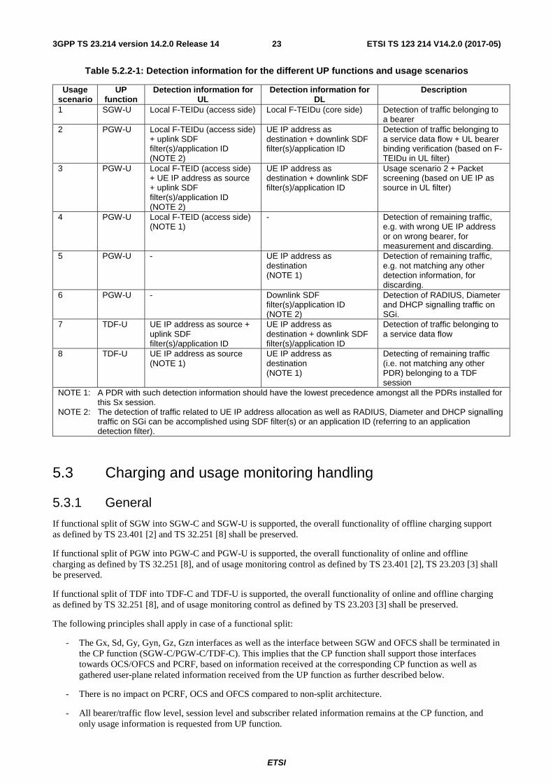
Table 5.2.2-1: Detection information for the different UP functions and usage scenarios
Usage scenario
UP function
Detection information for UL
Detection information for DL
Description
1 SGW-U Local F-TEIDu (access side) Local F-TEIDu (core side) Detection of traffic belonging to a bearer
2 PGW-U Local F-TEIDu (access side) + uplink SDF filter(s)/application ID (NOTE 2)
UE IP address as destination + downlink SDF filter(s)/application ID
Detection of traffic belonging to a service data flow + UL bearer binding verification (based on F-TEIDu in UL filter)
3 PGW-U Local F-TEID (access side) + UE IP address as source + uplink SDF filter(s)/application ID (NOTE 2)
UE IP address as destination + downlink SDF filter(s)/application ID
Usage scenario 2 + Packet screening (based on UE IP as source in UL filter)
4 PGW-U Local F-TEID (access side) (NOTE 1)
- Detection of remaining traffic, e.g. with wrong UE IP address or on wrong bearer, for measurement and discarding.
5 PGW-U - UE IP address as destination (NOTE 1)
Detection of remaining traffic, e.g. not matching any other detection information, for discarding.
6 PGW-U - Downlink SDF filter(s)/application ID (NOTE 2)
Detection of RADIUS, Diameter and DHCP signalling traffic on SGi.
7 TDF-U UE IP address as source + uplink SDF filter(s)/application ID
UE IP address as destination + downlink SDF filter(s)/application ID
Detection of traffic belonging to a service data flow
8 TDF-U UE IP address as source (NOTE 1)
UE IP address as destination (NOTE 1)
Detecting of remaining traffic (i.e. not matching any other PDR) belonging to a TDF session
NOTE 1: A PDR with such detection information should have the lowest precedence amongst all the PDRs installed for this Sx session.
NOTE 2: The detection of traffic related to UE IP address allocation as well as RADIUS, Diameter and DHCP signalling traffic on SGi can be accomplished using SDF filter(s) or an application ID (referring to an application detection filter).
5.3 Charging and usage monitoring handling
5.3.1 General
If functional split of SGW into SGW-C and SGW-U is supported, the overall functionality of offline charging support as defined by TS 23.401 [2] and TS 32.251 [8] shall be preserved.
If functional split of PGW into PGW-C and PGW-U is supported, the overall functionality of online and offline charging as defined by TS 32.251 [8], and of usage monitoring control as defined by TS 23.401 [2], TS 23.203 [3] shall be preserved.
If functional split of TDF into TDF-C and TDF-U is supported, the overall functionality of online and offline charging as defined by TS 32.251 [8], and of usage monitoring control as defined by TS 23.203 [3] shall be preserved.
The following principles shall apply in case of a functional split:
- The Gx, Sd, Gy, Gyn, Gz, Gzn interfaces as well as the interface between SGW and OFCS shall be terminated in the CP function (SGW-C/PGW-C/TDF-C). This implies that the CP function shall support those interfaces towards OCS/OFCS and PCRF, based on information received at the corresponding CP function as well as gathered user-plane related information received from the UP function as further described below.
- There is no impact on PCRF, OCS and OFCS compared to non-split architecture.
- All bearer/traffic flow level, session level and subscriber related information remains at the CP function, and only usage information is requested from UP function.

ETSI
ETSI TS 123 214 V14.2.0 (2017-05)243GPP TS 23.214 version 14.2.0 Release 14
5.3.2 Activation of usage reporting in UP function
Triggered by the PCC/ADC rules received from the PCRF or preconfigured information available at PGW-C/TDF-C/SGW-C, as well as from the OCS for online charging via Credit-Control session mechanisms, the CP function (PGW-C/TDF-C/SGW-C) shall provide Usage Reporting Rules to the UP function (PGW-U/TDF-U/SGW-U) for controlling how usage reporting is performed.
The CP function shall request the report of the relevant usage information for Usage Monitoring, based on Monitoring Keys and triggers which are specified in TS 23.203 [3] and TS 29.212 [11]. Each Usage Reporting Rule requested for usage monitoring control contains a list of "traffic flows" for PGW-U and TDF-U whose traffic is to be accounted under this rule. The CP function shall use Monitoring-key either preconfigured or received from the PCRF within the PCC/ADC Rule in order to generate this list and also shall keep the mapping between them. This list may overlap across multiple Usage-Report-Rules, i.e. multiple different Usage Reporting Rules may contain the same "traffic flows".
The CP function shall request the report of the relevant usage information for offline and online charging, based on Rating Groups and triggers which are specified in TS 32.251 [8]. Each Usage Reporting Rule requested for offline or online charging contains a list of "traffic flows" for PGW-U and TDF-U whose traffic is to be accounted under this rule. The CP function shall use Rating Group or Sponsor Identity either preconfigured or provided by PCRF and/or OCS as defined in TS 32.251 [8] and the PCC/ADC rule in order to generate this list and also shall keep the mapping between them. This list may overlap across multiple Usage-Report-Rules, i.e. multiple different Usage Reporting Rules may contain the same "traffic flows".
The CP function shall also provide reporting trigger events to the UP function for when to report usage information. The reporting trigger events (e.g. triggers, threshold information etc.) shall be supported for the session (IP-CAN/TDF) level reporting as well as on Rule level basis as determined by the CP function. The triggers may be provided as a volume, time or event to cater for the different charging/usage monitoring models supported by the TS 23.203 [3] for usage monitoring and by TS 32.251 [8] for offline and online charging. The CP function shall decide on the thresholds value(s) based on allowance received from PCRF, OCS or based on local configuration.
In some cases, the same Usage Reporting Rule can be used for different purposes (for both usage monitoring and charging), e.g. in case the same set of traffic flows, measurement method, trigger event, threshold, etc. apply. Similarly a reported measurement can be used for different purposes by the CP function.
5.3.3 Reporting of usage information towards CP function
The UP function shall support reporting of usage information to the CP function. The UP function shall be capable to support reporting based on different triggers, including:
- Periodic reporting with period defined by the CP function.
- Usage thresholds provided by the CP function.
- Report on demand received from the CP function.
The CP function shall make sure that the multiple granularity levels required by the reporting keys in the Usage Reporting rules satisfy the following aggregation levels without requiring a knowledge of the granularity levels by the UP function:
- Session level reporting (IP-CAN/TDF session);
- Bearer (for charging)/traffic flow (for both charging and usage monitoring) level reporting as defined by the reporting keys in the Usage Reporting Rule (see the description above).
Based on the mapping between Monitoring-key and PCC/ADC rule stored at the CP function, the CP function shall combine the reported information with session and subscriber related information which is available at the CP function, for Usage Monitoring reporting over the corresponding Gx, Sd interfaces.
Based on the mapping between Rating Group or Sponsor Identity and PCC/ADC rule stored at the CP function, the CP function shall combine the reported information with session and subscriber related information which is available at the CP function, for offline and online charging reporting over the corresponding Gy, Gyn, Gz, Gzn interfaces.
This functionality is specified in TS 32.240 [9].

ETSI
ETSI TS 123 214 V14.2.0 (2017-05)253GPP TS 23.214 version 14.2.0 Release 14
The usage information shall be collected in the UP function and reported to the CP function as defined in 5.3.3, based on Monitoring Keys and triggers which are specified in TS 23.203 [3] and TS 29.212 [11].
5.3.4 PGW Pause of Charging
When the UE moves to ECM-IDLE state and the SGW-C decides to activate buffering in SGW-U for the session, it shall also instruct the SGW-U to measure the number of packets/bytes that are buffered or discarded in SGW-U and the criteria for reporting within the Usage Reporting Rule.
Once the trigger of reporting is met, the SGW-U shall inform the SGW-C by reporting usage information.
The SGW-C can then inform the PGW-C as described in TS 23.401 [2].
When the PGW-C determines to stop the charging and usage monitoring actions for the PDN connection, it shall indicate the PGW-U to stop collecting the usage information.
PGW-C sends an Sx session modification request message to the PGW-U and modifies all the Usage Reporting Rules within the PDN connection to indicate the usage collection shall be stopped. When PGW-C determines to continue the charging action for the PDN connection, it sends an Sx session modification request message to the PGW-U and modifies all the Usage Reporting Rules within the PDN connection to indicate the usage collection shall be resumed.
NOTE: The support for PGW pause of charging is optional as described in TS 23.401 [2], and used only if both the SGW-C and the PGW-C support this feature.
5.4 GTP-U IP address and TEIDu allocation
5.4.1 General
Allocation and release of F-TEIDu is performed by SGW and PGW when a bearer needs to be established or released. If functional split into SGW-C/PGW-C and SGW-U/PGW-U is supported, F-TEIDu allocation and release can either be done in the CP function or in the UP function, as described in clauses 5.4.2 and 5.4.3 below.
The support of F-TEIDu allocation by the CP function is mandatory, and the support of F-TEIDu allocation by the UP function is optional. The UP function shall support F-TEIDu allocation by the CP function. The CP function optionally supports F-TEIDu allocation by the UP function.
Whether F-TEIDu allocation/release is performed by CP function or UP function is determined by network configuration of the CP functions. When both F-TEIDu allocation in CP function and F-TEIDu allocation in UP function coexist in the same network, the same F-TEIDu allocation option shall be used by all the CP functions controlling a particular UP function.
5.4.2 F-TEIDu allocation / release in the CP function
If the network is configured to perform allocation/release of F-TEIDu in the SGW-C, the SGW-C shall manage the SGW F-TEIDu space, including ensuring that the allocated F-TEIDu(s) are unique as described in TS 29.060 [6]. The SGW-C shall allocate F-TEIDu(s) for the applicable SGW-U reference points when a bearer is activated and release the F-TEIDu(s) when a bearer is deactivated. In case of bearer activation, the SGW-C shall provide the allocated F-TEIDu(s) to SGW-U. The SGW-C shall also provide the F-TEIDu(s) to other network entities as described in TS 23.401 [2] in order to complete the bearer establishment. In case of bearer deactivation, the SGW-C shall notify the SGW-U about the release of the F-TEIDu(s).
If network is configured to perform allocation/release of F-TEIDu in the PGW-C, the PGW-C shall manage the PGW F-TEIDu space, including ensuring that the allocated F-TEIDu(s) are unique as described in TS 29.060 [6]. The PGW-C shall allocate F-TEIDu(s) for the applicable PGW-U reference points when a bearer is activated and release the F-TEIDu(s) when a bearer is deactivated. In case of bearer activation, the PGW-C shall provide the allocated F-TEIDu(s) to PGW-U. The PGW-C shall also provide the F-TEIDu(s) to other network entities as described in TS 23.401 [2] and TS 23.402 [4] in order to complete the bearer establishment. In case of bearer deactivation, the PGW-C shall notify the PGW-U about the release of the F-TEIDu(s).

ETSI
ETSI TS 123 214 V14.2.0 (2017-05)263GPP TS 23.214 version 14.2.0 Release 14
5.4.3 F-TEIDu allocation / release in the UP function
If the network is configured to perform allocation/release of F-TEIDu in the SGW-U, the SGW-U shall manage the SGW F-TEIDu space, including ensuring that the allocated F-TEIDu(s) are unique as described in TS 29.060 [6]. In case of bearer activation, the SGW-C shall request SGW-U to allocate F-TEIDu(s) for the applicable SGW-U reference points and provide them to the SGW-C. The SGW-C shall provide the F-TEIDu(s) to other network entities as described in TS 23.401 [2] in order to complete the bearer establishment. In case of bearer deactivation, the SGW-C shall request SGW-U to release F-TEIDu(s) for the bearer.
If the network is configured to perform allocation/release of F-TEIDu in the PGW-U, the PGW-U shall manage the PGW F-TEIDu space, including ensuring that the allocated F-TEIDu(s) are unique as described in TS 29.060 [6]. In case of bearer activation, the PGW-C shall request PGW-U to allocate F-TEIDu(s) for the applicable PGW-U reference points and provide them to the PGW-C. The PGW-C shall provide the F-TEIDu(s) to other network entities as described in TS 23.401 [2] and TS 23.402 [4] in order to complete the bearer establishment. In case of bearer deactivation, the PGW-C shall request PGW-U to release F-TEIDu(s) for the bearer.
5.5 UE IP address management (allocation, renewal and release)
The UE IP address management includes allocation and release of the UE IP address as well as renewal of the allocated IP address, where applicable.
The UE IP address management shall be performed by the PGW-C. As part of this functionality, various UE IP address management mechanisms as defined in 3GPP TS 23.401 [2] clause 5.3.1 are supported by the PGW-C. The PGW-C shall process the UE IP address management related messages, maintain the corresponding state information and provide the response messages to the UE. In case the UE IP address is obtained from the external PDN, additionally, the PGW-C shall also send the allocation, renewal and release related request messages to the external PDN and maintain the corresponding state information. The PGW-U shall support forwarding of the UE IP address management related messages to the PGW-C, when they are received via the user plane signalling from the UE or from the external PDN.
When PGW-C performs IPv4 address allocation via default bearer activation and release via PDN connection release (3GPP TS 23.401 [2] clause 5.3.1.2.1), no special functionality is required from the PGW-U.
For the other UE IP address management mechanisms, the UE sends the IP address management related request messages via the user plane signalling. Hence the PGW-U is required to forward these request messages to the PGW-C for processing. Once these request messages are processed by the PGW-C, the PGW-C sends response messages to the UE via the user plane signalling. Hence the PGW-C is required to forward these response messages to the PGW-U so that it can be relayed it to the UE. Correspondingly, following functionality is required to be supported by the PGW-C and PGW-U:
- For IPv6 default prefix management via IPv6 stateless address autoconfiguration (3GPP TS 23.401 [2] clause 5.3.1.2.2): PGW-C shall configure PGW-U to forward Router Solicitation and Neighbor Solicitation messages from the UE to the PGW-C. The PGW-C shall forward Router Advertisement and Neighbor Advertisement messages to the PGW-U for relaying them to the UE.
- For IPv6 parameter configuration via stateless DHCPv6 (3GPP TS 23.401 [2] clause 5.3.1.2.3): PGW-C shall configure PGW-U to forward all the DHCPv6 messages from the UE to the PGW-C. The PGW-C shall forward the DHCPv6 response messages to the PGW-U for relaying them to the UE.
- For IPv4 address management and parameter configuration DHCPv4 (3GPP TS 23.401 [2] clause 5.3.1.2.4): PGW-C shall configure PGW-U to forward all the DHCPv4 messages from the UE to the PGW-C. The PGW-C shall forward the DHCPv4 response messages to PGW-U for relaying them to the UE.
- For IPv6 prefix management via IPv6 prefix delegation (3GPP TS 23.401 [2] clause 5.3.1.2.6): PGW-C shall configure PGW-U to forward all the DHCPv6 messages from the UE to the PGW-C. The PGW-C shall forward the DHCPv6 response messages to PGW-U for relaying them to the UE.
In addition to the above, when the UE IP address is obtained from the external PDN, following functionality is required to be supported by the PGW-C and PGW-U:
- For UE IP address from AAA server in the external PDN: If the AAA server in the external PDN is reachable only via the PGW-U the PGW-C shall configure the PGW-U to forward all the Diameter or RADIUS messages
ETSI
ETSI TS 123 214 V14.2.0 (2017-05)273GPP TS 23.214 version 14.2.0 Release 14
from the AAA server in the external PDN to the PGW-C. And the PGW-C shall forward the Diameter or RADIUS messages to the PGW-U for relaying them to the AAA server in the external PDN.
- For UE IP address from DHCPv4/v6 server in the external PDN: If the DHCPv4/v6 server in the external PDN is reachable only via the PGW-U the PGW-C shall configure the PGW-U to forward all the DHCPv4/v6 messages from the DHCPv4/v6 server in the external PDN to the PGW-C. And the PGW-C shall forward the DHCPv4/v6 messages to the PGW-U for relaying them to the DHCPv4/v6 server in the external PDN.
NOTE: If the AAA server or the DHCPv4/v6 server in the external PDN is reachable directly, then the PGW-C communicates with it directly, without involving the PGW-U.
5.6 Control of user plane forwarding
5.6.1 General
One of the main tasks of the Sx interface is to enable the CP function to instruct the UP function about how to forward user data traffic. There are several different user plane forwarding scenarios supported. Some scenarios are applicable to SGW only or PGW only, while other scenarios are applicable to SGW and PGW or PGW and TDF. A non-exhaustive list of forwarding scenarios is provided in Table 5.6.2-1 below.
The CP function shall be able to provide the UP with instructions for at least the following behaviors: forward, forward with end marker. The CP function shall also be able to request multiple sets of forwarding instructions to be performed in sequence, e.g. forward to the DL side and forward to the CP function for the purpose of duplication.
5.6.2 Control of user plane forwarding
The CP function controls user-plane packet forwarding for traffic detected by a PDR by providing FAR(s) with instructions to the UP function, including:
- Forwarding operation information;
- Forwarding target information.
The details of the forwarding target and operation will depend on the scenario and is described in Table 5.6.2-1 below. The following forwarding functionality is required by the UP function (more than one forwarding scenario can be active for the same traffic):
- Apply GTP-U bearer related handling, i.e. encapsulation, de-capsulation or both. (This covers scenario 1 in the table below).
- Forward the traffic to the CP function (This covers scenario 2, 3, 4 in the table below).
- Apply locally configured policy for traffic steering. (This covers scenario 5 in the table below).
Further details on the forwarding related information are provided in clause 7.5.

ETSI
ETSI TS 123 214 V14.2.0 (2017-05)283GPP TS 23.214 version 14.2.0 Release 14
Table 5.6.2-1: Forwarding information for different scenarios
Scenario description Forwarding target and operation Applicable to 1 Forwarding of user-plane between UE and
PDN, including mapping onto GTP-U tunnels and mapping between GTP-U tunnels
GTP-U encapsulation information (F-TEID) SGW, PGW
2 Forwarding of user-plane packets from UE and CP function (e.g. RS/RA, DHCPv4/v6, traffic subject to HTTP redirect etc)
Information that the CP function is source/target (CP function IP address)
PGW
3 Forwarding of packets from the external PDN / SGi and the CP function (e.g. for RADIUS, Diameter and DHCP signalling, traffic subject to HTTP redirect etc)
Information that the CP function is source/target (CP function IP address)
PGW
4 Forwarding of packets subject to buffering in CP function
Information that the CP function is source/target (CP function IP address)
SGW
5 Forwarding of packets between the UP function and the SGi-LAN for Flexible Mobile Service Chaining
Reference to a predefined traffic steering configuration (e.g. Traffic-Steering Policy identifier)
PGW, TDF
5.6.3 Format of forwarded user plane data
For forwarding between the CP function and UP function the user plane packet is forwarded outside of the control protocol over Sx by encapsulating the user-plane packet using a UP encapsulation protocol that allows the receiving entity to identify which PDN Connection and which bearer the traffic belongs to. In the direction from the CP function to UP function for forwarding towards the UE or PDN, the UP encapsulation protocol also shall contain information that allows the UP function to identify whether the UE or PDN is targeted.
NOTE: The encapsulation format for the user plane data between CP function and UP function is to be determined by stage 3.
5.7 UE's permanent identifier usage For the scenarios requiring UE's permanent identity at the UP function, e.g. UP function performing http header enrichment in a trusted environment, the UE's permanent identity may be provided from the CP function to the UP function in a container, instead of in an Sx parameter.
NOTE: In an untrusted environment in which the UE's permanent identity cannot be provided, due to e.g. to fulfil the privacy requirements, the session identifier is used between the CP function and UP function for correlating UE's session related events.
5.8 Functionality of sending of "end marker" Sending of "end marker" is a functionality which involve SGW-C and SGW-U, and PGW-C and PGW-U. As part of the functionality, constructing of end marker packets can either be done in the CP function or in the UP function, as described in clauses 5.8.1 and 5.8.2. Whether constructing of end marker packets is performed by CP function or UP function is determined by network configuration.
5.8.1 UP function constructing the "end marker" packets
In case of eNodeB relocation during handover procedure without SGW-U change, SGW-C shall indicate the SGW-U to switch the S1 path(s) by sending an Sx session modification request message with the new F-TEID-u of eNodeB and in addition, provide an indication to the SGW-U to send the end marker packet(s) on the old path.
On receiving this indication, the SGW-U shall construct end marker packet(s) and send it for each S1 GTP-U tunnel towards the source eNodeB after sending the last PDU on the old path.
In case of SGW-U relocation during handover procedure, PGW-C shall indicate the PGW-U to switch the S5/S8 path(s) by sending an Sx session modification request message (bearer ID, new F-TEID of SGW-U) and in addition, provide an indication to the PGW-U to send the end marker packet(s) on the old path.

ETSI
ETSI TS 123 214 V14.2.0 (2017-05)293GPP TS 23.214 version 14.2.0 Release 14
On receiving this indication, the PGW-U shall construct end marker packet(s) and send it for each S5/S8 GTP-U tunnel towards the source SGW-U after sending the last PDU on the old path.
On receiving the end marker packet(s) on S5/S8 GTP-U tunnel, SGW-U shall forward the end marker packet(s) and send it for each S1 GTP-U tunnel towards the source eNodeB.
5.8.2 CP function constructing the "end marker" packets
In case of eNodeB relocation during handover procedure without SGW-U change, SGW-C shall indicate the SGW-U to switch the S1 path(s) by sending an Sx session modification request message (bearer ID, new F-TEID of eNodeB). After sending the last PDU on the old path, SGW-U shall replace the old F-TEID with the new one and responds with an Sx session modification response message to acknowledge the success of path switch.
When the path switch is finished, SGW-C constructs the end marker packet(s) and sends it to the SGW-U. SGW-U then forwards the packet(s) to the source eNodeB.
In case of SGW-U relocation during handover procedure, PGW-C shall indicate the PGW-U to switch the S5/S8 path(s) by sending an Sx session modification request message (bearer ID, new F-TEID of SGW-U). After sending the last PDU on the old S5/S8 path, PGW-U shall replace the old F-TEID with the new one and responds with an Sx session modification response message to acknowledge the success of path switch.
When the path switch is finished, PGW-C constructs the end marker packet(s) and sends it to PGW-U. PGW-U then forwards the packet(s) to the source SGW-U.
5.9 Idle state packet SGW buffering function
5.9.1 General
Buffering of the UE's data packets for the UE in idle or power saving mode can be performed in SGW-U or SGW-C.
The support of buffering in the SGW-U is mandatory and the SGW-C shall support buffering by the SGW-U.
The support of buffering in the SGW-C is optional and the SGW-U optionally supports buffering by the SGW-C. An exception is that in a dedicated core network serving UEs which may enter power saving mode or apply eDRX, e.g. NB-IoT UEs, the SGW-C shall support buffering capability.
When buffering is supported in both SGW-C and SGW-U, the SGW-C decides on a per UE session basis (e.g. based on local configuration and other information such as UE capability) to perform buffering in either the SGW-C or the SGW-U.
5.9.2 Buffering in CP function
When the UE moves to ECM-IDLE state, if the SGW-C supports buffering capability and decides to activate buffering, the SGW-C shall inform the SGW-U to stop sending data packets to eNodeB and start forwarding the downlink data packets towards the SGW-C.
When the UE transition to the ECM-CONNECTED state, the SGW-C shall update the SGW-U via Sxa interface with the F-TEIDu of the eNodeB. If there are buffered packets available and their buffering duration has not expired, the SGW-C shall forward those packets to the SGW-U outside of the control plane signalling (see clause 5.6.3 "Format of forwarded user plane data") to relay them to the UE. These packets are then forwarded by the SGW-U to the eNodeB.
5.9.3 Buffering in UP function
5.9.3.1 General
The SGW-C shall be able to provide the SGW-U with instructions for at least the following behaviors: buffer without reporting the arrival of first downlink packet, buffer with reporting the arrival of first downlink packet, drop packets.
When the UE moves to ECM-IDLE state, if the SGW-C does not support buffering capability, or if the SGW-C supports buffering capability and decides to activate buffering in SGW-U for the session, the SGW-C shall inform the

ETSI
ETSI TS 123 214 V14.2.0 (2017-05)303GPP TS 23.214 version 14.2.0 Release 14
SGW-U, via a Sx session modification. The SGW-C decides whether buffering timers are handled by the SGW-U or by the SGW-C. The activation of buffering implicitly stops sending data to the eNodeB/RNC/SGSN.
After starting the buffering, when the first downlink packet arrives on any bearer, SGW-U shall inform the SGW-C. SGW-U sends an Sx reporting message to the SGW-C unless specified otherwise and identifies the S5/S8 bearer on which the downlink packet was received.
On receiving this reporting message, the SGW-C decides whether to send a Downlink Data Notification message to the MME as defined in TS 23.401 [2].
At the UE transition to ECM-CONNECTED state, the SGW-C shall update the SGW-U via Sxa interface with the F-TEIDu of the eNodeB/RNC/SGSN. The buffered data packets, if any, are then forwarded to the eNodeB/RNC/SGSN by the SGW-U.
In case of SGW-U relocation, buffered data packets are transferred from the old SGW-U to the new SGW-U.
5.9.3.2 Delay Downlink Packet Notification
According to clause 5.3.4.2 of TS 23.401 [2], the MME/SGSN may inform the SGW that for all UEs served by the MME/SGSN, the Downlink Packet Data Notification shall be delayed for a period D.
If the parameter D is handled by the SGW-U, the SGW-C shall include the parameter D in the Sx session establishment for new Sx sessions, in the Sx session modification for Sx sessions which are not in buffering state (when transitioning these sessions to the buffering state), and in the next Sx report ack message for Sx sessions already in buffering state. The SGW-U shall then delay the sending of subsequent Sx reporting upon next DL data arrival.
If the parameter D is handled by the SGW-C, there is no special handling compared to clause 5.9.3.1. When the SGW-U reports the arrival of a DL data packet, the SGW-C shall delay the sending of the Downlink Data Notification to the MME by parameter D delay.
5.9.3.3 Extended buffering
According to clauses 5.3.4.3 and 5.7.3 of TS 23.401 [2], the MME/SGSN invoking extended buffering indicates it to the Serving GW in the Downlink Data Notification Ack message, includes a DL Buffering Duration time and optionally a DL Buffering Suggested Packet Count.
If the MME/SGSN included the DL Suggested Packet Count, the SGW-C shall include the DL Suggested Packet Count in the Sx reporting Ack message.
If the DL Data Buffer Expiration Time is handled by the SGW-U, the SGW-C includes it in the Sx reporting Ack message and requests the SGW-U to buffer DL data packets. When the SGW-U receives the DL Data Buffer Expiration Time, the SGW-U buffers the DL data packets without reporting the arrival of the first DL data packet until the DL Data Buffer Expiration Time expires. When the DL Data Buffer Expiration Time expires, the SGW-U shall discard the buffered DL packets and shall restart buffering DL data packets with reporting the arrival of the first DL data packet.
If the DL Data Buffer Expiration Time is handled by the SGW-C, the SGW-C requests the SGW-U to buffer the DL data packets without reporting the arrival of the first DL data packet. When the DL Data Buffer Expiration Time expires, the SGW-C requests the SGW-U to drop the buffered data packets and to start buffering the DL data packets with reporting of the arrival of the first DL data packet, via a Sx Session Modification.
If the DL Suggested Packet Count was included in the request from the SGW-C, the SGW-U buffers the DL data packets up to the number of packets indicated by the DL Suggested Packet Count.
5.9.3.4 Throttling
According to clause 4.3.7.4.1a of TS 23.401 [2], the MME/SGSN can request the SGWs to selectively reduce the number of Downlink Data Notification requests it sends for downlink non-priority traffic received for UEs in idle mode according to a throttling factor and for a throttling delay specified in the Downlink Data Notification Ack message.
Throttling mechanism by which the MME uses Downlink Data Notification Acknowledgement messages DL low priority traffic Throttling parameters, is handled by the SGW-C as follows:

ETSI
ETSI TS 123 214 V14.2.0 (2017-05)313GPP TS 23.214 version 14.2.0 Release 14
- On receiving Downlink Data Notification Acknowledgement from the MME/SGSN, the SGW-C determines which bearers are subject to the throttling of Downlink Data Notification requests on the basis of the bearer's ARP priority level and the operator policy.
- Upon receipt of an Sx report notifying the arrival of DL data packets on those bearers, the SGW-C decides whether or not to send a DDN to MME based on the requested throttling factor. The SGW-C may indicate in the Sx Report Ack whether SGW-U shall discard the buffered packet and may also indicate whether SGW-U shall notify when additional DL packets arrive.
- The throttling delay timer and throttling factor are handled by the SGW-C and not provided to SGW-U.
5.10 Bearer and APN policing ARP is used for admission control (i.e. retention and pre-emption of the bearer). The value of ARP is not required to be provided to the UP function.
For every bearer, SGW-C/PGW-C shall use the QCI and optionally, the ARP priority level, to determine the transport level packet marking and provide the transport level packet marking to the SGW-U/PGW-U.
PGW-C shall provide the APN-AMBR value together with a QoS Enforcement Rule correlation ID (as described in clause 7.6) to PGW-U so that the PGW-U can enforce the APN-AMBR across all IP-CAN sessions of the UE to the same APN at the PGW-U.
SGW-C/PGW-C shall provide the GBR and MBR value for each GBR bearer of the PDN connection to the SGW-U/PGW-U. When the Gn/Gp interface is used by the PGW-U, PGW-C shall also provide the MBR value to the PGW-U for each non-GBR bearer of the PDN connection on the Gn/Gp interface.
TDF-C shall provide the TDF session MBR value to TDF-U to be applied to the TDF session of the UE.
5.11 PCC/ADC related functions
5.11.1 Activation/Deactivation of predefined PCC/ADC rules
A predefined PCC/ADC rule is configured in the CP function.
The traffic detection filters required in the UP function can be configured either in the CP function and provided to the UP function, as service data flow filter(s), or be configured in the UP function, as the application detection filter identified by an application identifier. For the latter case, the application identifier has to be configured in the UP function.
The traffic steering policy information can be configured in the UP function.
Policies for traffic handling in the UP function, which are referred by some identifiers corresponding to the parameters of a PCC/ADC rule, can be configured in the UP function.
When a predefined PCC/ADC rule is activated/deactivated by the PCRF, PGW-C/TDF-C shall decide what information has to be provided to the PGW-U/TDF-U to enforce the rule based on where the traffic detection filters (i.e. service data flow filter(s) or application detection filter), traffic steering policy information and the policies used for the traffic handling in the UP function are configured and where they are enforced:
- If the predefined PCC/ADC rule contains an application identifier for which corresponding application detection filters are configured in the UP function, the PGW-C/TDF-C shall provide a corresponding application identifier to the UP function;
- If the predefined PCC/ADC rule contains traffic steering policy identifier(s), the PGW-C/TDF-C shall provide a corresponding forwarding policy to the UP function;
- If the predefined PCC/ADC rule contains service data flow filter(s), the PGW-C/TDF-C shall provide them to the PGW-U/TDF-U;

ETSI
ETSI TS 123 214 V14.2.0 (2017-05)323GPP TS 23.214 version 14.2.0 Release 14
- If the predefined PCC/ADC rule contains some parameters for which corresponding policies for traffic handling in the UP function are configured in the UP function, the PGW-C/TDF-C shall activate those traffic handling policies via their rule ID(s).
The CP function shall maintain the mapping between a PCC/ADC rule received over Gx/Sd and the flow level PDR rule(s) used on Sx.
5.11.2 Enforcement of dynamic PCC/ADC rules
The application detection filters required in the UP function can be configured either in the CP function and provided to the UP function as the service data flow filter, or be configured in the UP function identified by an application identifier.
When receiving a dynamic PCC/ADC rule from the PCRF which contains an application identifier and/or parameters for traffic handling in the UP function:
- if the application detection filter is configured in the PGW-C/TDF-C, the PGW-C/TDF-C shall provide it in the service data flow filter to the UP function, as well as parameters for traffic handling in the UP function received from the dynamic PCC/ADC rule;
- otherwise, the application detection filters is configured in UP function, the PGW-C/TDF-C shall provide to PGW-U/TDF-U with the application identifier and the parameters for traffic handling in the UP function as required based on the dynamic PCC/ADC rule.
The CP function shall maintain the mapping between a PCC/ADC rule received over Gx/Sd and the flow level PDR(s) used on Sx.
5.11.3 Redirection
The uplink application's traffic redirection may be enforced either in the PGW-C/TDF-C (as specified in 5.4.2 Control of user plane forwarding) or directly in the UP function. The redirect destination may be provided in the dynamic PCC/ADC rule or be preconfigured, either in the CP function or in the UP function.
When receiving redirect information (redirection enabled/disabled and redirect destination) within a dynamic PCC/ADC rule or being activated/deactivated by the PCRF for the predefined redirection policies, PGW-C/TDF-C shall decide whether to provide and what information to be provided to the UP function based on where the redirection is enforced and where the redirect destination is acquired/preconfigured. When redirection is enforced in the UP function and the redirect destination is acquired from the dynamic PCC/ACD rule or is configured in the CP function, CP function shall provide the redirect destination to the UP function. When redirection is enforced in the CP function, CP function shall instruct the UP function to forward applicable user plane traffic to the CP function.
5.11.4 Support of SDCI
PFDF shall provide PFD (s) to the PGW-C/TDF-C on the request of PGW-C/TDF-C (pull mode) or on the request of PFD management from SCEF (push mode), as described in TS 23.203 [3]. The PGW-C/TDF-C shall provide the PFD (s) to the PGW-U/TDF-U, on which the Application ID corresponding to the PFD(s) is active, for the enforcement.
The PGW-C/TDF-C supports the procedures for Gw/Gwn as specified in TS 23.203 [3], for management of PFDs. PFD (s) is cached in the PGW-C/TDF-C, and the PGW-C/TDF-C maintains a caching timer associated to the PFD (s). When the caching timer expires and there's no active PCC/ADC rule that refers to the corresponding application identifier, the PGW-C/TDF-C informs the PGW-U/TDF-U to remove the PFD(s) identified by the application identifier using the PFD management message.
When a PDR is provided for an Application ID corresponding to the PFD(s) that are not already provided to the PGW-U/TDF-U, the PGW-C/TDF-C shall provide the PFD (s) to the PGW-U/TDF-U (if there are no PFD(s) cached, the PGW-C/TDF-C retrieves them from the PFDF as specified in TS 23.203 [3]). When any update of the PFD(s) is received from PFDF by PGW-C/TDF-C (using "push" or "pull" mode), and there are still active PDRs in PGW-U/TDF-U for the Application ID, the PGW-C/TDF-C shall provision/update/remove the PFD(s) using the PFD management message.
NOTE 1: PGW-C/TDF-C should assure not to overload Sx signalling while managing PFD(s) to the UP function, e.g. forwarding the PFD(s) to the right UP function where the PFD(s) is enforced.

ETSI
ETSI TS 123 214 V14.2.0 (2017-05)333GPP TS 23.214 version 14.2.0 Release 14
When the PGW-U/TDF-U receives the updated PFD(s) from either the same or different PGW-C/TDF-C for the same application identifier, the latest received PFD(s) shall overwrite any existing PFD(s) stored in the UP function.
NOTE 2: For the case a single UP function is controlled by multiple CP functions, the conflict of PFD(s) corresponding to the same application identifier provided by different CP functions should be avoided by operator enforcing a well-planned PFDF and CP/UP function deployment.
5.12 User Plane function selection
5.12.1 General
The selection of the UP function (SGW-U, PGW-U, TDF-U, combined SGW/PGW-U) is performed by its respective CP function (SGW-C, PGW-C, TDF-C, combined SGW/PGW-C).
The UP function's capabilities shall be signalled during the initial connection establishment between the CP function and the UP function.
The CP function shall be made dynamically aware on the UP function load and relative static capacity for which it has an established Sx session as specified in the clauses below.
The exact set of parameters used for the selection mechanism is deployment specific and controlled by the operator configuration, e.g. location information may be used for selecting UP function in some deployments while may not be used in other deployments.
5.12.2 Selection of PGW-U
For PGW-U selection, the PGW-C shall be able to consider the following parameters:
- the PGW-U's dynamic load, at the node level (the PGW-C may then derive the load at the APN level);
- the PGW-U's relative static capacity (among PGW-Us supporting the same APN);
- the PGW-U location configured in the PGW-C and the UE location information provided by the MME/SGSN in order to select the appropriate PGW-U, e.g. for SIPTO above RAN service;
- the capability of the UP function and the functionality required for the particular UE session: An appropriate UP function can be selected by matching the functionality and features required for an UE (which can be derived from the information received over S11/S4/S5/S8 (e.g. APN, mapped UE Usage Type, UE location information) or from the PCRF (e.g. need to perform DPI)) with the capabilities of the UP function so as to fulfil the service for the UE, e.g. if L7 based traffic detection is needed then an UP function supporting corresponding functionality needs to be selected.
- to enable APN-AMBR enforcement, whether a PDN connection already exists for the same UE and APN, in which case the same PGW-U shall be selected;
The criteria for PGW-U selection may include load balancing between PGW-Us.
The PGW-C may support the Sx Load Control feature.
In order to allow the PGW-C to select a PGW-U according to above parameters:
- the SGW-C may provide the mapped UE Usage Type over the S5 interface.
5.12.3 Selection of SGW-U
For SGW-U selection, the SGW-C shall be able to consider the following parameters:
- the SGW-U location (e.g. SGW Service Area) and the UE location information, provided by the MME/SGSN in order to select a UP function close to the UE's point of attachment;
- the SGW-U's dynamic load;

ETSI
ETSI TS 123 214 V14.2.0 (2017-05)343GPP TS 23.214 version 14.2.0 Release 14
- the SGW-U's relative static capacity (versus other SGW-Us);
- the capability of the UP function and the functionality required for the particular UE session: An appropriate UP function can be selected by matching the functionalities and features required for an UE (which can be derived from the information received over S11/S5 (e.g. individual CIoT capabilities, UE Usage Type, the APN (for selection of combined SGW/PGW)) with the capabilities of the UP function so as to fulfil the service requirement for the UE then a UP function supporting corresponding functionality needs to be selected.
The criteria for SGW-U selection may include load balancing between SGW-Us.
The SGW-C may support the Sx Load Control feature.
In order to allow the SGW-C to select a SGW-U according to the above parameters:
- the MME/SGSN shall provide the location of the UE (i.e. ECGI, eNB or TAI for E-UTRAN, and RAI or RNC-ID for UTRAN), the APN (for selection of a combined SGW/PGW) and may provide the mapped UE Usage Type in the Create Session Request over the S5 interface;
5.12.4 Selection of a combined SGW/PGW-U
A combined SGW/PGW-C selects the SGW-U and PGW-U as defined respectively in clauses 5.12.3 and 5.12.4, with the following addition:
- The SGW-C determines that it is a combined SGW/PGW-C entity the same way as in the non-split case;
- The combined SGW/PGW-C may optimize UP function selection by selecting the best couple of SGW-U and PGW-U for the requested APN, among all candidate couples of (SGW-U, PGW-U), instead of selecting independently the SGW-U first and then the PGW-U (which may result in selecting non-co-located SGW-U and PGW-U).
5.12.5 Selection of TDF-U
5.12.5.1 Solicited application reporting mode
TDF-C shall select TDF-U at PDN connection establishment (TDF session establishment).
The selection may be based on the following parameters:
- the TDF-U's dynamic load;
- the TDF-U's relative static capacity;
- the capability of the UP function and the functionalities and the capabilities required for the particular UE session: An appropriate UP function can be selected by matching the functionalities and features required for the UE from the PCRF.
The criteria for TDF-U selection includes load balancing between TDF-Us.
The TDF-C may support the Sx Load Control feature.
5.12.5.2 Unsolicited application reporting mode
The selection of TDF-U for the unsolicited application reporting is performed by TDF-C during the Sx management procedure, using the information configured in TDF-C.
NOTE: TDF-C provides the instructions for application detection and reporting to the TDF-U during the Sx session management procedure. TDF-U shall communicate with the TDF-C (using the same Sx session) when application reporting is necessary, based on instructions provided by TDF-C.

ETSI
ETSI TS 123 214 V14.2.0 (2017-05)353GPP TS 23.214 version 14.2.0 Release 14
6 Information flows Editor's note: This clause will document the Sx information flows and their usage for the various existing
procedures.
6.1 General Editor's note: After stage 3 finalized the work on Sx management procedures and Sx node level reporting
procedures, the corresponding descriptions could be added into this TS.
This clause defines the procedures that are used for the interaction between SGW-C and SGW-U, PGW-C and PGW-U, TDF-C and TDF-U, and documents how these procedures shall be embedded into existing procedures of TS 23.401 [2], TS 23.402 [4], TS 23.060 [5] and TS 23.203 [3].
NOTE: TS 23.401 [2], TS 23.402 [4], TS 23.060 [5] and TS 23.203 [3] do not reflect control and user plane separation of SGW, PGW or TDF and thus the procedures in these specifications do not show the interaction between the respective CP function and UP function. In case of any discrepancies, the procedures defined in TS 23.401 [2], TS 23.402 [4], TS 23.060 [5] and TS 23.203 [3] apply.
6.2 Sx Session Management Procedures
6.2.1 General
Sx session management procedures are used to control the functionality of the UP function, which involve SGW, PGW or TDF. The CP function can create, update and remove the Sx session context (i.e. the parameters related to a PDN connection, IP-CAN session, TDF session or TDF in unsolicited reporting mode) in the UP function.
The following Sx session management procedures exist: Sx session establishment procedure, Sx session modification procedure and Sx session termination procedure. All of them are initiated by the CP function.
Editor's note: Additional procedures (or types of interaction) may be required and will be added when identified.
6.2.2 Sx Session Establishment Procedure
The Sx session establishment procedure is used to create the initial Sx session context for a PDN connection, IP-CAN session, TDF session or TDF in unsolicited reporting mode at the UP function.
During PDN connection establishment, the Sx session establishment procedure is executed between SGW-C and SGW-U as well as PGW-C and PGW-U. The Sx session context comprises the parameters for the default as well as every dedicated bearer of the PDN connection. In addition, the Sx session context for the PGW-U comprises IP-CAN session related parameters.
During SGW-U relocation, the Sx session establishment procedure is executed between SGW-C and the target SGW-U. The Sx session context comprises the parameters for the default as well as every dedicated bearer of the PDN connection.
During TDF session establishment, the Sx session establishment procedure is executed between TDF-C and TDF-U. The Sx session context comprises TDF session related parameters.
For a TDF in unsolicited reporting mode, the Sx session establishment procedure is executed between TDF-C and the TDF-U selected during Sx management procedure. The Sx session context comprises the instructions for application detection and reporting in unsolicited reporting mode.

ETSI
ETSI TS 123 214 V14.2.0 (2017-05)363GPP TS 23.214 version 14.2.0 Release 14
UP function
2.Sx Session Establishment Request
CP function
3.Sx Session Establishment Response
1.Trigger to establish new PDN connection or TDF session
4.Interaction with other network entity
Figure 6.2.2-1 Sx session establishment procedure
NOTE: In case of a TDF in unsolicited reporting mode, the procedure is triggered by TDF configuration and step 1 and 4 do not apply.
1. CP function receives the trigger to establish a new PDN connection or TDF session from a peer CP function, an MME or a PCRF.
2. The CP function sends an Sx session establishment request message to the UP function that contains the structured control information which defines how the UP function needs to behave.
3. The UP function responds with an Sx session establishment response message containing any information that the UP function has to provide to the CP function in response to the control information received.
4. The CP function interacts with the network entity which triggered this procedure (e.g. a peer CP function, an MME or a PCRF).
6.2.3 Sx Session Modification Procedure
The Sx session modification procedure is used to update the Sx session context of an existing PDN connection, IP-CAN session, TDF session or TDF in unsolicited reporting mode at the UP function.
The Sx session modification procedure is executed between SGW-C and SGW-U whenever PDN connection related parameters have to be modified, as well as between PGW-C and PGW-U whenever PDN connection or IP-CAN session related parameters have to be modified.
The Sx session modification procedure is executed between TDF-C and TDF-U whenever TDF session related parameters have to be modified.
For a TDF in unsolicited reporting mode, the Sx session modification procedure is executed between TDF-C and TDF-U whenever instructions for application detection and reporting have to be modified.
UP function
2.Sx Session Modification Request
CP function
3.Sx Session Modification Response
1.Trigger to modify PDN connection or TDF session
4.Interaction with other network entity
Figure 6.2.3-1 Sx session modification procedure
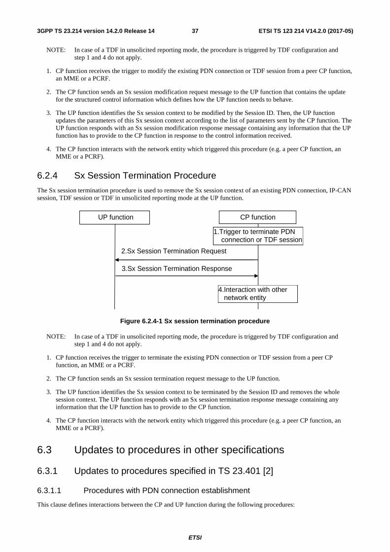
ETSI
ETSI TS 123 214 V14.2.0 (2017-05)373GPP TS 23.214 version 14.2.0 Release 14
NOTE: In case of a TDF in unsolicited reporting mode, the procedure is triggered by TDF configuration and step 1 and 4 do not apply.
1. CP function receives the trigger to modify the existing PDN connection or TDF session from a peer CP function, an MME or a PCRF.
2. The CP function sends an Sx session modification request message to the UP function that contains the update for the structured control information which defines how the UP function needs to behave.
3. The UP function identifies the Sx session context to be modified by the Session ID. Then, the UP function updates the parameters of this Sx session context according to the list of parameters sent by the CP function. The UP function responds with an Sx session modification response message containing any information that the UP function has to provide to the CP function in response to the control information received.
4. The CP function interacts with the network entity which triggered this procedure (e.g. a peer CP function, an MME or a PCRF).
6.2.4 Sx Session Termination Procedure
The Sx session termination procedure is used to remove the Sx session context of an existing PDN connection, IP-CAN session, TDF session or TDF in unsolicited reporting mode at the UP function.
UP function
2.Sx Session Termination Request
CP function
3.Sx Session Termination Response
1.Trigger to terminate PDN connection or TDF session
4.Interaction with other network entity
Figure 6.2.4-1 Sx session termination procedure
NOTE: In case of a TDF in unsolicited reporting mode, the procedure is triggered by TDF configuration and step 1 and 4 do not apply.
1. CP function receives the trigger to terminate the existing PDN connection or TDF session from a peer CP function, an MME or a PCRF.
2. The CP function sends an Sx session termination request message to the UP function.
3. The UP function identifies the Sx session context to be terminated by the Session ID and removes the whole session context. The UP function responds with an Sx session termination response message containing any information that the UP function has to provide to the CP function.
4. The CP function interacts with the network entity which triggered this procedure (e.g. a peer CP function, an MME or a PCRF).
6.3 Updates to procedures in other specifications
6.3.1 Updates to procedures specified in TS 23.401 [2]
6.3.1.1 Procedures with PDN connection establishment
This clause defines interactions between the CP and UP function during the following procedures:

ETSI
ETSI TS 123 214 V14.2.0 (2017-05)383GPP TS 23.214 version 14.2.0 Release 14
- E-UTRAN initial attach (TS 23.401 [2] clause 5.3.2.1)
- UE requested PDN connectivity (TS 23.401 [2] clause 5.10.2)
During the above procedures following is the nature of interactions between the CP and UP function:
- The new SGW-C selects a new SGW-U and creates Sxa session
- The new PGW-C selects a new PGW-U and creates Sxb session
- The old SGW-C releases the existing Sxa session from the old SGW-U
- The old PGW-C releases the existing Sxa session from the old PGW-U
- The SGW-C modifies the SGW-U to update with the F-TEIDu of the eNodeB

ETSI
ETSI TS 123 214 V14.2.0 (2017-05)393GPP TS 23.214 version 14.2.0 Release 14
UE RAN MMENew
SGW-C
New
SGW-U
Old
SGW-C
Old
SGW-UPGW-C PGW-U HSS PCRF
1. E-UTRAN initial attach Figure 5.3.2.1-1 steps 1-7
2a. Sx Session
Termination Request
2b. Sx Session
Termination Response
4. E-UTRAN initial attach Figure 5.3.2.1-1 steps 8-10
7. E-UTRAN initial attach Figure 5.3.2.1-1 steps 11-12 or
UE requested PDN connectivity Figure 5.10.2-1 steps 1-2
11. E-UTRAN initial attach Figure 5.3.2.1-1 steps 15 or
UE requested PDN connectivity Figure 5.10.2-1 steps 5
3a. Sx Session
Termination Request
3b. Sx Session
Termination Response
6a. Sx Session
Termination Request
6b. Sx Session
Termination Response
8a. Sx Session Establishment Request
8b. Sx Session Establishment Response
10a. Sx Session Establishment Request
10b. Sx Session Establishment Response
9. E-UTRAN initial attach Figure 5.3.2.1-1 steps 13-14 or
UE requested PDN connectivity Figure 5.10.2-1 steps 3-4
12a. Sx Session Modification Request
12b. Sx Session Modification Response
13. E-UTRAN initial attach Figure 5.3.2.1-1 steps 16-23 or
UE requested PDN connectivity Figure 5.10.2-1 steps 6-13
14a. Sx Session Modification Request
14b. Sx Session Modification Response
15. E-UTRAN initial attach Figure 5.3.2.1-1 steps 23a or
UE requested PDN connectivity Figure 5.10.2-1 steps 13a
16a. Sx Session Modification Request
16b. Sx Session Modification Response
17. E-UTRAN initial attach Figure 5.3.2.1-1 steps 24-26 or
UE requested PDN connectivity Figure 5.10.2-1 steps 14-16
5a. Sx Session
Termination Request
5b. Sx Session
Termination Response
Figure 6.3.1.1-1: Interaction between CP and UP function with PDN connection establishment

ETSI
ETSI TS 123 214 V14.2.0 (2017-05)403GPP TS 23.214 version 14.2.0 Release 14
1. Procedure as listed in this step is initiated as specified in the relevant clauses of this specification. The relevant steps of the procedure as specified in the figure above are executed.
2a. The SGW-C may send an Sx Session Termination Request to the SGW-U to release the Sx session.
2b. The SGW-U sends an Sx Session Termination Response to the SGW-C confirming the release of the Sx session.
3a. The PGW-C may send an Sx Session Termination Request to the PGW-U to release the Sx session.
3b. The PGW-U sends an Sx Session Termination Response to the PGW-C confirming the release of the Sx session.
4. The relevant steps of the procedure as specified in the figure above are executed.
5a. The SGW-C may send an Sx Session Termination Request to the SGW-U to release the Sx session.
5b. The SGW-U sends an Sx Session Termination Response to the SGW-C confirming the release of the Sx session.
6a. The PGW-C may send an Sx Session Termination Request to the PGW-U to release the Sx session.
6b. The PGW-U sends an Sx Session Termination Response to the PGW-C confirming the release of the Sx session.
7. The relevant steps of the procedure as specified in the figure above are executed.
8a. The SGW-C shall select new SGW-U as specified in clause 5.12. If the network is configured to perform F-TEIDu allocation in the CP function then SGW-C allocates F-TEIDu for each and every bearer. Then the SGW-C sends an Sx Session Establishment Request to the selected SGW-U for creating Sxa session for the UE. The F-TEIDu for each and every bearer shall be included if the SGW-C has allocated the same. The Usage Monitoring Rules may also be included in case of home-routed roaming scenario and if the inter-operator charging is required.
8b. If the network is configured to perform F-TEIDu allocation in the UP function, the SGW-U allocates F-TEIDu for all received bearers. The SGW-U sends an Sx Session Establishment Response to the SGW-C confirming the successful creation of the Sxa session. It shall include the F-TEIDu for each and every bearer if it has allocated the same.
9. The relevant steps of the procedure as specified in the figure above are executed.
10a. The PGW-C shall select new PGW-U as specified in clause 5.12. If the network is configured to perform F-TEIDu allocation in the CP function then PGW-C allocates F-TEIDu for each and every bearer. Then the PGW-C sends an Sx Session Establishment Request to the selected PGW-U for creating Sxb session for the UE. The F-TEIDu for each and every bearer shall be included if the PGW-C has allocated the same. The Traffic Handling Rules shall also be included.
10b. If the network is configured to perform F-TEIDu allocation in the UP function, the PGW-U allocates F-TEIDu all received bearers. The PGW-U sends an Sx Session Establishment Response to the PGW-C confirming the successful creation of the Sxb session. It shall include the F-TEIDu for each and every bearer if it has allocated the same.
11. The relevant steps of the procedure as specified in the figure above are executed.
12a. The SGW-C sends Session Modification Request to the SGW-U. The SGW-C shall include the F-TEIDu of the PGW-U.
12b. The SGW-U sends an Sx Session Modification Response to the SGW-C confirming the success of the Sxa session modification.
13. The relevant steps of the procedure as specified in the figure above are executed.
14a. The SGW-C sends an Sx Session Modification Request to the SGW-U. The SGW-C shall include the F-TEIDu of the eNodeB.
14b. The SGW-U sends an Sx Session Modification Response to the SGW-C confirming the success of the Sxa session modification.
15. The relevant steps of the procedure as specified in the figure above are executed.
ETSI
ETSI TS 123 214 V14.2.0 (2017-05)413GPP TS 23.214 version 14.2.0 Release 14
16a. If the Handover Indication is included in step 15, the PGW-C updates the old PGW-U session corresponding to the non-3GPP access by sending "Sx session modification request" message to the PGW-U (session ID) and instructs the PGW-U to start routing the downlink packets to the SGW/SGW-U.
16b. The PGW-U sends "Sx session modification response" message to the PGW-C.
17. The relevant steps of the procedure as specified in the figure above are executed.
6.3.1.2 Procedures with SGW change
6.3.1.2.1 General
This clause covers the following two types of procedures involving SGW change:
- Type 1: Procedures in which only Create Session Request message is sent from MME/SGSN to SGW-C during SGW change.
- Type 2: Procedures in which Create Session Request message followed by Modify Bearer Request message are sent from MME/SGSN to SGW-C during SGW change.
6.3.1.2.2 Type 1
This clause defines interactions between the CP and UP function during the following procedures:
- Tracking Area Update procedure with Serving GW change (TS 23.401 [2] clause 5.3.3.1)
- Routing Area Update with MME interaction and with SGW change (TS 23.401 [2] clause 5.3.3.6)
- X2-based handover with Serving GW relocation (TS 23.401 [2] clause 5.5.1.1.3)
- MME triggered Serving GW relocation (TS 23.401 [2] clause 5.10.4)
Editor's Note: "Tracking Area Update procedure with Serving GW change and data forwarding" (TS 23.401 [2] clause 5.3.3.1A) is FFS.
During the above procedures following is the nature of interactions between the CP and UP function:
- The new SGW-C selects a new SGW-U and creates Sxa session
- The PGW-C modifies the PGW-U to update with the identity of the new SGW-U
- The old SGW-C releases the existing Sxa session from the old SGW-U

ETSI
ETSI TS 123 214 V14.2.0 (2017-05)423GPP TS 23.214 version 14.2.0 Release 14
UE RAN MMENew
SGW-C
New
SGW-U
Old
SGW-C
Old
SGW-UPGW-C PGW-U HSS PCRF
1. Tracking Area Update procedure
with Serving GW change Figure 5.3.3.1-1 steps 1-8 or
Routing Area Update with MME interaction
and with SGW change Figure 5.3.3.6-1 steps 1-7 or
X2-based handover with Serving GW relocation Figure 5.5.1.1.3-1 steps 1-2 or
MME triggered Serving GW relocation Figure 5.10.4-1 steps 1-2
2. Session Establishment Request
3. Session Establishment Response
4. Tracking Area Update procedure
with Serving GW change Figure 5.3.3.1-1 steps 9a or
Routing Area Update with MME interaction
and with SGW change Figure 5.3.3.6-1 steps 9 or
X2-based handover with Serving GW relocation Figure 5.5.1.1.3-1 steps 3a or
MME triggered Serving GW relocation Figure 5.10.4 steps 3a
5. Session Modification Request
6. Session Modification Response
7. Tracking Area Update procedure
with Serving GW change Figure 5.3.3.1-1 steps 10-18 or
Routing Area Update with MME interaction
and with SGW change Figure 5.3.3.6-1 steps 10-16 or
X2-based handover with Serving GW relocation Figure 5.5.1.1.3-1 steps 3b-7a or
MME triggered Serving GW relocation Figure 5.10.4 steps 3b-6a
8. Session Release Request
9. Session Release Response
10. Tracking Area Update procedure
with Serving GW change Figure 5.3.3.1-1 steps 19 onwards or
Routing Area Update with MME interaction
and with SGW change Figure 5.3.3.6-1 steps 17 onwards or
X2-based handover with Serving GW relocation Figure 5.5.1.1.3-1 steps 7b onwards or
MME triggered Serving GW relocation Figure 5.10.4 steps 6b onwards
Figure 6.3.1.2.2-1: Interaction between CP and UP function during procedures with SGW change (Type 1)
1. Procedure as listed in this step is initiated as specified in the relevant clauses of this specification. The relevant steps of the procedure as specified in the figure above are executed.
2. The new SGW-C shall select new SGW-U as specified in clause 5.12. If the network is configured to perform F-TEIDu allocation in the CP function then SGW-C allocates F-TEIDu for each and every bearer. Then the new SGW-C sends Session Establishment Request to the selected SGW-U for creating Sxa session for the UE. Additionally, F-TEIDu for each and every bearer shall be included if the SGW-C has allocated the same. The Usage Monitoring Rules may also be included in case of home-routed roaming scenario and if the inter-operator charging is required.
3. If the network is configured to perform F-TEIDu allocation in the UP function, the SGW-U allocates F-TEIDu for each and every bearer received. The new SGW-U sends Session Establishment Response to the new SGW-C confirming the successful creation of the Sxa session. It shall include the F-TEIDu for each and every bearer if it has allocated the same.
4. The relevant steps of the procedure as specified in the figure above are executed.
5. The PGW-C sends Session Modification Request to the PGW-U. The PGW-C shall include the F-TEIDu of the new SGW-U. Additionally, based on the interaction with the PCRF, the PGW-C may also update the Policy Rules and the Usage Monitoring Rules for the PDN session.

ETSI
ETSI TS 123 214 V14.2.0 (2017-05)433GPP TS 23.214 version 14.2.0 Release 14
6. The PGW-U sends Session Modification Response to the PGW-C confirming the success of the Sxb session modification.
7. The relevant steps of the procedure as specified in the figure above are executed.
8. The old SGW-C sends Session Release Request to the old SGW-U to release the UE session.
9. The old SGW-U sends Session Release Response to the old SGW-C confirming the release of the UE session.
10. The relevant steps of the procedure as specified in the figure above are executed.
6.3.1.2.3 Type 2
This clause defines interactions between the CP and UP function during the following procedures:
- S1-based handover, normal (TS 23.401 [2] clause 5.5.1.2.2)
- E-UTRAN to UTRAN Iu mode Inter RAT handover (TS 23.401 [2] clause 5.5.2.1)
- UTRAN Iu mode to E-UTRAN Inter RAT handover (TS 23.401 [2] clause 5.5.2.2)
- E-UTRAN to GERAN A/Gb mode Inter RAT handover (TS 23.401 [2] clause 5.5.2.3)
- GERAN A/Gb mode to E-UTRAN Inter RAT handover (TS 23.401 [2] clause 5.5.2.4)
Editor's Note: Most of the above procedures involve establishment and release of indirect data forwarding tunnel at the source and the target SGW. It is FFS if this needs to be supported in the CP and UP split architecture.
During the above procedures following is the nature of interactions between the CP and UP function:
- The new SGW-C selects a new SGW-U and creates Sxa session.
- The SGW-C modifies the Sxa session at SGW-U to update the identity of the eNB.
- The PGW-C modifies the PGW-U to update with the identity of the new SGW-U.
- The old SGW-C releases the existing Sxa session from the old SGW-U.
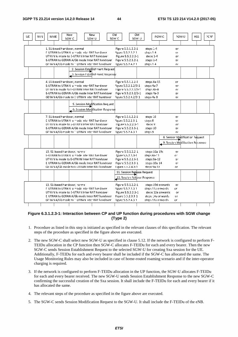
ETSI
ETSI TS 123 214 V14.2.0 (2017-05)443GPP TS 23.214 version 14.2.0 Release 14
Figure 6.3.1.2.3-1: Interaction between CP and UP function during procedures with SGW change (Type 2)
1. Procedure as listed in this step is initiated as specified in the relevant clauses of this specification. The relevant steps of the procedure as specified in the figure above are executed.
2. The new SGW-C shall select new SGW-U as specified in clause 5.12. If the network is configured to perform F-TEIDu allocation in the CP function then SGW-C allocates F-TEIDu for each and every bearer. Then the new SGW-C sends Session Establishment Request to the selected SGW-U for creating Sxa session for the UE. Additionally, F-TEIDu for each and every bearer shall be included if the SGW-C has allocated the same. The Usage Monitoring Rules may also be included in case of home-routed roaming scenario and if the inter-operator charging is required.
3. If the network is configured to perform F-TEIDu allocation in the UP function, the SGW-U allocates F-TEIDu for each and every bearer received. The new SGW-U sends Session Establishment Response to the new SGW-C confirming the successful creation of the Sxa session. It shall include the F-TEIDu for each and every bearer if it has allocated the same.
4. The relevant steps of the procedure as specified in the figure above are executed.
5. The SGW-C sends Session Modification Request to the SGW-U. It shall include the F-TEIDu of the eNB.
UE RAN MMENew
SGW-C
New
SGW-U
Old
SGW-C
Old
SGW-UPGW-C PGW-U HSS PCRF
1. S1-based handover, normal Figure 5.5.1.2.2-1 steps 1-4 or
E-UTRAN to UTRAN Iu mode Inter RAT handover Figure 5.5.2.1.2-1 steps 1-4 or
UTRAN Iu mode to E-UTRAN Inter RAT handover Figure 5.5.2.2.2-1 steps 1-4 or
E-UTRAN to GERAN A/Gb mode Inter RAT handover Figure 5.5.2.3.2-1 steps 1-4 or
GERAN A/Gb mode to E-UTRAN Inter RAT handover Figure 5.5.2.4.2-1 steps 1-4 or
2. Session Establishment Request
3. Session Establishment Response
4. S1-based handover, normal Figure 5.5.1.2.2-1 steps 4a-15 or
E-UTRAN to UTRAN Iu mode Inter RAT handover Figure 5.5.2.1.2/3-1 steps 4a-7 or
UTRAN Iu mode to E-UTRAN Inter RAT handover Figure 5.5.2.2.2/3-1 steps 4a-8 or
E-UTRAN to GERAN A/Gb mode Inter RAT handover Figure 5.5.2.3.2/3-1 steps 4a-9 or
GERAN A/Gb mode to E-UTRAN Inter RAT handover Figure 5.5.2.4.2/3-1 steps 4a-8 or
8. Session Modification Request
9. Session Modification Response
7. S1-based handover, normal Figure 5.5.1.2.2-1 steps 16 or
E-UTRAN to UTRAN Iu mode Inter RAT handover Figure 5.5.2.1.3-1 steps 8 or
UTRAN Iu mode to E-UTRAN Inter RAT handover Figure 5.5.2.2.3-1 steps 9 or
E-UTRAN to GERAN A/Gb mode Inter RAT handover Figure 5.5.2.3.3-1 steps 10 or
GERAN A/Gb mode to E-UTRAN Inter RAT handover Figure 5.5.2.4.3-1 steps 9 or
11. Session Release Request
12. Session Release Response
10. S1-based handover, normal Figure 5.5.1.2.2-1 steps 16a-19c or
E-UTRAN to UTRAN Iu mode Inter RAT handover Figure 5.5.2.1.3-1 steps 8a-11 or
UTRAN Iu mode to E-UTRAN Inter RAT handover Figure 5.5.2.2.3-1 steps 9a-12 or
E-UTRAN to GERAN A/Gb mode Inter RAT handover Figure 5.5.2.3.3-1 steps 10a-14 or
GERAN A/Gb mode to E-UTRAN Inter RAT handover Figure 5.5.2.4.3-1 steps 9a-13 or
5. Session Modification Request
6. Session Modification Response
13. S1-based handover, normal Figure 5.5.1.2.2-1 steps 19d onwards or
E-UTRAN to UTRAN Iu mode Inter RAT handover Figure 5.5.2.1.3-1 steps 11a onwards or
UTRAN Iu mode to E-UTRAN Inter RAT handover Figure 5.5.2.2.3-1 steps 12a onwards or
E-UTRAN to GERAN A/Gb mode Inter RAT handover Figure 5.5.2.3.3-1 steps 14a onwards or
GERAN A/Gb mode to E-UTRAN Inter RAT handover Figure 5.5.2.4.3-1 steps 13a onwards or
ETSI
ETSI TS 123 214 V14.2.0 (2017-05)453GPP TS 23.214 version 14.2.0 Release 14
6. The SGW-U sends Session Modification Response to the SGW-C confirming the successful modification of the Sxa session.
7. The relevant steps of the procedure as specified in the figure above are executed.
8. The PGW-C sends Session Modification Request to the PGW-U. The PGW-C shall include the F-TEIDu of the new SGW-U. Additionally, based on the interaction with the PCRF, the PGW-C may also update the Policy Rules and the Usage Monitoring Rules for the PDN session.
9. The PGW-U sends Session Modification Response to the PGW-C confirming the success of the Sxb session modification.
10. The relevant steps of the procedure as specified in the figure above are executed.
11. The old SGW-C sends Session Release Request to the old SGW-U to release the UE session.
12. The old SGW-U sends Session Release Response to the old SGW-C confirming the release of the UE session.
13. The relevant steps of the procedure as specified in the figure above are executed.
6.3.1.3 Procedures with eNB F-TEIDu update
In this clause, interactions between the CP and UP function during the following procedures are considered:
- UE triggered Service Request (TS 23.401 [2] clause 5.3.4.1).
- Connection Resume procedure (TS 23.401 [2] clause 5.3.5A).
- E-UTRAN initiated E-RAB modification procedure (TS 23.401 [2] clause 5.4.7).
- X2-based handover without Serving GW relocation (TS 23.401 [2] clause 5.5.1.1.2).
- S1-based handover without Serving GW change (TS 23.401 [2] clause 5.5.1.2.2).
During the above procedures following is the nature of interactions between the CP and UP function:
- The SGW-C modifies the Sxa session at SGW-U to update the identity of the eNB.
- Based on the interaction with the PCRF, the PGW-C may modify the PGW-U to update with new Usage Monitoring or Policy rules.

ETSI
ETSI TS 123 214 V14.2.0 (2017-05)463GPP TS 23.214 version 14.2.0 Release 14
UE RAN MME SGW-C SGW-U PGW-C PGW-U HSS PCRF
1. UE triggered Service Request Figure 5.3.4.1-1 steps 1-8 or
Connection Resume procedure Figure 5.3.5A-1 steps 1-7 or
E-UTRAN initiated E-RAB modification procedure Figure 5.4.7-1 steps 1-2 or
X2-based handover without Serving GW relocation Figure 5.5.1.1.2-1 steps 1-2 or
S1-based handover without Serving GW change Figure 5.5.1.2.2-1 steps 1-15
2. Session Modification Request
3. Session Modification Response
4. UE triggered Service Request Figure 5.3.4.1-1 steps 9 or
Connection Resume procedure Figure 5.3.5A-1 steps 8 onwards or
E-UTRAN initiated E-RAB modification procedure Figure 5.4.7-1 steps 3 onwards or
X2-based handover without Serving GW relocation Figure 5.5.1.1.2-1 steps 3a or
S1-based handover without Serving GW change Figure 5.5.1.2.2-1 steps 16 onwards
5. Session Modification Request
6. Session Modification Response
7. UE triggered Service Request Figure 5.3.4.1-1 steps 10 onwards or
X2-based handover without Serving GW relocation Figure 5.5.1.1.2-1 steps 3b onwards
Figure 6.3.1.3-1: Interaction between CP and UP function during procedures with eNB F-TEIDu update
1. Procedure as listed in this step is initiated as specified in the relevant clauses of this specification. The relevant steps of the procedure as specified in the figure above are executed.
2. The SGW-C sends Session Modification Request to the SGW-U. It shall include the new F-TEIDu of the eNB. Additionally, for the following procedures extra steps may apply:
- UE triggered Service Request: If the buffering of the data packets in the idle mode is performed in the SGW-C and if those buffered packets are still valid (e.g. data packets for which the buffering duration hasn't expired yet), then SGW-C shall also provide those data packets to the SGW-U (as specified in clause 5.12) so that it can be sent to the eNB.
3. The SGW-U sends Session Modification Response to the SGW-C confirming the successful modification of the Sxa session.
4. The relevant steps of the procedure as specified in the figure above are executed.
5. Based on the interaction with the PCRF, the PGW-C may update the Policy Rules and the Usage Monitoring Rules for the PDN session. Correspondingly, the PGW-C sends Session Modification Request to the PGW-U.
6. The PGW-U sends Session Modification Response to the PGW-C confirming the success of the Sxb session modification.
7. The relevant steps of the procedure as specified in the figure above are executed.
6.3.1.4 Procedures with release of eNB F-TEIDu
This clause defines interactions between the CP and UP function during the following procedures:
- Connection Suspend procedure (TS 23.401 [2] clause 5.3.4A)
- S1 release procedure (TS 23.401 [2] clause 5.3.5)
During the above procedures following is the nature of interactions between the CP and UP function:
- The SGW-C modifies the SGW-U to release the eNB F-TEIDu. Additionally, the SGW-C configures the SGW-U so that the downlink data packets can be buffered either in the SGW-C or in the SGW-U.

ETSI
ETSI TS 123 214 V14.2.0 (2017-05)473GPP TS 23.214 version 14.2.0 Release 14
Figure 6.3.1.4-1: Interaction between CP and UP function during procedures with release of eNB F-TEIDu
1. Procedure as listed in this step is initiated as specified in the relevant clauses of this specification. The relevant steps of the procedure as specified in the figure above are executed.
2. The SGW-C sends Session Modification Request to the SGW-U. It shall indicate the SGW-U to release the eNB F-TEIDu. Additionally, the SGW-C decides if the buffering of the downlink data packets shall be done in CP or the UP function, as specified in clause 5.9) and correspondingly informs the SGW-U for as follows:
- If the downlink data packets are to be buffered in the SGW-C, the SGW-C shall configure the SGW-U to forward the downlink data packets for all the bearers of the UE to the SGW-C, as specified in clause 5.6.
- If the downlink data packets are to be buffered in the SGW-U, the SGW-C shall indicate the same to SGW-U. Additionally, the following applies:
- if the Paging Policy Differentiation feature (as specified in 3GPP TS 23.401 [2] clause 4.9) is supported by the SGW-C and SGW-U and based on operator's policy if it is required to be activated for this UE, the SGW-C shall include an indication to provide the DSCP in TOS (IPv4) / TC (IPv6) value from the IP header of the first downlink data packet of each bearer.
- if the PDN GW Pause Charging procedure (as specified in 3GPP TS 23.401 [2] clause 5.3.6A) is supported by the SGW-C and SGW-U and based on operator's policy if it is required to be activated for this UE, the SGW-C may provide the number/fraction of packets/bytes drop threshold value. When this threshold is reached, the SGW-U is required to provide an indication to the SGW-C.
3. The SGW-U sends Session Modification Response to the SGW-C confirming the successful modification of the Sxa session.
4. The relevant steps of the procedure as specified in the figure above are executed.
6.3.1.5 Procedures when downlink data is buffered in the UP function
This clause defines interactions between the CP and UP function when then UE is in idle mode and buffering of the downlink data is performed in the UP function, during the following procedures:
- Network Triggered Service Request (TS 23.401 [2] clause 5.3.4.3)
- PDN GW Pause of Charging procedure (TS 23.401 [2] clause 5.3.6A)
During the above procedures following is the nature of interactions between the CP and UP function:
- The SGW-C modifies the SGW-U to release the eNB F-TEIDu. Additionally, the SGW-C configures the SGW-U so that the downlink data packets can be buffered either in the SGW-C or in the SGW-U.
UE RAN MME SGW-C SGW-U PGW-C PGW-U HSS PCRF
1. Connection Suspend procedure Figure 5.3.4A-1 steps 1-2 or
S1 release procedure Figure 5.3.5-1 steps 1-2 or
2. Session Modification Request
3. Session Modification Response
4. Connection Suspend procedure Figure 5.3.4A-1 steps 3 onwards or
S1 release procedure Figure 5.3.5-1 steps 3 onwards

ETSI
ETSI TS 123 214 V14.2.0 (2017-05)483GPP TS 23.214 version 14.2.0 Release 14
Figure 6.3.1.5-1: Interaction between CP and UP when downlink data is buffered in the UP function
1. Procedure as listed in this step is initiated as specified in the relevant clauses of this specification. The relevant steps of the procedure as specified in the figure above are executed.
2. When the downlink data is received, the SGW-U starts buffering it.
On arrival of the first downlink data packet, the SGW-U shall send Data Notification message ( first packet indication) to the SGW-C. If the Paging Policy Differentiation feature (as specified in 3GPP TS 23.401 [2] clause 4.9) is supported by the SGW-U and if it is activated by the SGW-C for this Sxa session, the SGW-U shall also include the DSCP in TOS (IPv4) / TC (IPv6) value from the IP header of the downlink data packet.
Editor's note: How to identify the downlink packet in case of UP buffering is FFS.
If the SGW-C has provided the number/fraction of packets/bytes drop threshold value during the procedure with release of eNB F-TEIDu (clause 6.3.1.4), the SGW-U shall monitor that threshold. Once the threshold is reached the SGW-U shall send the Data Notification message (bearer id, drop threshold reached) to the SGW-C.
3. The relevant steps of the procedure as specified in the figure above are executed.
4. The SGW-C sends Data Notification Ack message to the SGW-U. Additionally, for the following procedures the following applies:
- Network Triggered Service Request: If DL Buffering Duration time and DL Buffering Suggested Packet Counts were received from the MME/SGSN (refer to step no. 2 of TS 23.401 [2] clause 5.3.4.3) by the SGW-C then SGW-C shall include the same in Data Notification Ack message.
5. The relevant steps of the procedure as specified in the figure above are executed.
6.3.1.6 Procedures with release of PDN connection
This clause defines interactions between the CP and UP function during the following procedures:
- UE-initiated Detach procedure for E-UTRAN (TS 23.401 [2] clause 5.3.8.2.1)
- UE-initiated Detach procedure for GERAN/UTRAN with ISR activated (TS 23.401 [2] clause 5.3.8.2.2)
- MME-initiated Detach procedure (TS 23.401 [2] clause 5.3.8.3)
- SGSN-initiated Detach procedure with ISR activated (TS 23.401 [2] clause 5.3.8.3A)
- HSS-initiated Detach procedure (TS 23.401 [2] clause 5.3.8.4)
- UE or MME requested PDN disconnection (TS 23.401 [2] clause 5.10.3)
During the above procedures following is the nature of interactions between the CP and UP function:
- The SGW-C terminates the Sxa session at the SGW-U.
- The PGW-C terminates the Sxb session at the PGW-U.
UE RAN MME SGW-C SGW-U PGW-C PGW-U HSS PCRF
1. Network Triggered Service Request Figure 5.3.4.3-1 steps 1 or
PDN GW Pause of Charging procedure Figure 5.3.6A-1 steps 1
4. Data Notification Ack
2. Data Notification
3. Network Triggered Service Request Figure 5.3.4.3-1 steps 2 or
PDN GW Pause of Charging procedure Figure 5.3.6A-1 steps 2
5. Network Triggered Service Request Figure 5.3.4.3-1 steps 3 onwards or
PDN GW Pause of Charging procedure Figure 5.3.6A-1 steps 3 onwards

ETSI
ETSI TS 123 214 V14.2.0 (2017-05)493GPP TS 23.214 version 14.2.0 Release 14
Figure 6.3.1.6-1: Interaction between CP and UP function during release of PDN connection
1. Procedure as listed in this step is initiated as specified in the relevant clauses of this specification. The relevant steps of the procedure as specified in the figure above are executed.
2. The SGW-C sends Session Termination Request to the SGW-U.
3. The SGW-U sends Session Termination Response to the SGW-C confirming the successful termination of the Sxa session. Additionally, if the usage reporting is configured by the SGW-C (as specified in clause 5.3.2) the SGW-U shall provide the usage report for the PDN connection (as specified in sec. 5.3.3) to the SGW-C.
Editor's note: Usage reporting is done as part of the Session Termination Response or separately using Sx Report procedure (as defined in clause 6.3.2) is FFS.
4. The relevant steps of the procedure as specified in the figure above are executed.
5. The PGW-C sends Session Termination Request to the PGW-U.
6. The PGW-U sends Session Termination Response to the PGW-C confirming the successful termination of the Sxb session. Additionally, if the usage reporting is configured by the PGW-C (as specified in clause 5.3.2) the PGW-U shall provide the usage report for the PDN connection (as specified in sec. 5.3.3) to the PGW-C.
Editor's note: Usage reporting is done as part of the Session Termination Response or separately using Sx Report procedure (as defined in clause 6.3.2) is FFS.
7. The relevant steps of the procedure as specified in the figure above are executed.
6.3.1.7 Procedures with modification of bearer
This clause defines interactions between the CP and UP function during the following procedures:
- Dedicated bearer activation (TS 23.401 [2] clause 5.4.1)
- PDN GW initiated bearer modification with bearer QoS update (TS 23.401 [2] clause 5.4.2.1)
UE RAN MME SGW-C SGW-U PGW-C PGW-U HSS PCRF
1. UE-initiated Detach procedure for E-UTRAN Figure 5.3.8.2-1 steps 1-5 or
UE-initiated Detach procedure for GERAN/UTRAN
with ISR activated Figure 5.3.8.2-2 steps 1-5 or
MME-initiated Detach procedure Figure 5.3.8.3-1 steps 1-5 or
SGSN-initiated Detach procedure with ISR activated Figure 5.3.8.3A-1 steps 1-5 or
HSS-initiated Detach procedure Figure 5.3.8.4-1 steps 1-3 or
UE or MME requested PDN disconnection Figure 5.10.3-1 steps 1-2
2. Session Termination Request
3. Session Termination Response
4. UE-initiated Detach procedure for E-UTRAN Figure 5.3.8.2-1 steps 6 or
UE-initiated Detach procedure for GERAN/UTRAN
with ISR activated Figure 5.3.8.2-2 steps 6 or
MME-initiated Detach procedure Figure 5.3.8.3-1 steps 6 or
SGSN-initiated Detach procedure with ISR activated Figure 5.3.8.3A-1 steps 6 or
HSS-initiated Detach procedure Figure 5.3.8.4-1 steps 4 or
UE or MME requested PDN disconnection Figure 5.10.3-1 steps 3
5. Session Termination Request
6. Session Termination Response
7. UE-initiated Detach procedure for E-UTRAN Figure 5.3.8.2-1 steps 7 onwards or
UE-initiated Detach procedure for GERAN/UTRAN
with ISR activated Figure 5.3.8.2-2 steps 7 onwards or
MME-initiated Detach procedure Figure 5.3.8.3-1 steps 7 onwards or
SGSN-initiated Detach procedure with ISR activated Figure 5.3.8.3A-1 steps 7 onwards or
HSS-initiated Detach procedure Figure 5.3.8.4-1 steps 5 onwards or
UE or MME requested PDN disconnection Figure 5.10.3-1 steps 4 onwards

ETSI
ETSI TS 123 214 V14.2.0 (2017-05)503GPP TS 23.214 version 14.2.0 Release 14
- PDN GW initiated bearer modification without bearer QoS update (TS 23.401 [2] clause 5.4.3)
- PDN GW initiated bearer deactivation (TS 23.401 [2] clause 5.4.4.1)
NOTE: Interactions between CP and UP during "HSS Initiated Subscribed QoS Modification" (3GPP TS 23.401 [2] clause 5.4.2.2) and "MME Initiated Dedicated Bearer Deactivation" (3GPP TS 23.401 [2] clause 5.4.4.2) procedures are also covered as part of the above procedures.
During the above procedures following is the nature of interactions between the CP and UP function:
- The PGW-C modifies the Sxb session at the PGW-U.
- The SGW-C terminates the Sxa session at the SGW-U.
Figure 6.3.1.7-1: Interaction between CP and UP function during modification of bearer
1. Procedure as listed in this step is initiated as specified in the relevant clauses of this specification. The relevant steps of the procedure as specified in the figure above are executed.
2. The PGW-C sends Session Modification Request to the PGW-U.
3. The PGW-U sends Session Modification Response to the PGW-C confirming the successful modification of the Sxa session.
4. The relevant steps of the procedure as specified in the figure above are executed.
5. The SGW-C sends Session Modification Request to the SGW-U.
6. The SGW-U sends Session Modification Response to the SGW-C confirming the successful modification of the Sxa session.
7. The relevant steps of the procedure as specified in the figure above are executed.
UE RAN MME SGW-C SGW-U PGW-C PGW-U HSS PCRF
1. Dedicated bearer activation Figure 5.4.1-1 steps 1-2 or
PDN GW initiated bearer modification with
bearer QoS update Figure 5.4.2.1-1 steps 1-2 or
PDN GW initiated bearer modification without
bearer QoS update Figure 5.4.3-1 steps 1-2 or
PDN GW initiated bearer deactivation Figure 5.4.4.1-1 steps 1-2 or
2. Session Modification Request
3. Session Modification Response
4. Dedicated bearer activation Figure 5.4.1-1 steps 3 or
PDN GW initiated bearer modification with
bearer QoS update Figure 5.4.2.1-1 steps 3 or
PDN GW initiated bearer modification without
bearer QoS update Figure 5.4.3-1 steps 3 or
PDN GW initiated bearer deactivation Figure 5.4.4.1-1 steps 3 or
5. Session Modification Request
6. Session Modification Response
7. Dedicated bearer activation Figure 5.4.1-1 steps 4 onwards or
PDN GW initiated bearer modification with
bearer QoS update Figure 5.4.2.1-1 steps 4 onwards or
PDN GW initiated bearer modification without
bearer QoS update Figure 5.4.3-1 steps 4 onwards or
PDN GW initiated bearer deactivation Figure 5.4.4.1-1 steps 4 onwards or
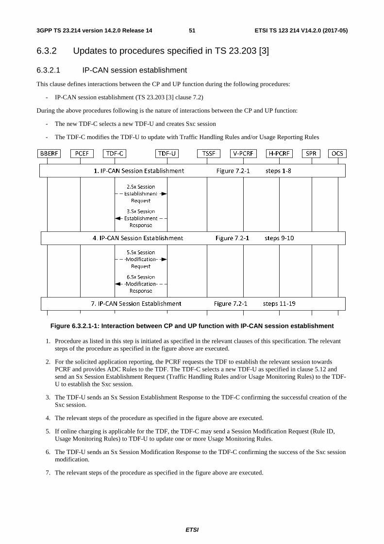
ETSI
ETSI TS 123 214 V14.2.0 (2017-05)513GPP TS 23.214 version 14.2.0 Release 14
6.3.2 Updates to procedures specified in TS 23.203 [3]
6.3.2.1 IP-CAN session establishment
This clause defines interactions between the CP and UP function during the following procedures:
- IP-CAN session establishment (TS 23.203 [3] clause 7.2)
During the above procedures following is the nature of interactions between the CP and UP function:
- The new TDF-C selects a new TDF-U and creates Sxc session
- The TDF-C modifies the TDF-U to update with Traffic Handling Rules and/or Usage Reporting Rules
Figure 6.3.2.1-1: Interaction between CP and UP function with IP-CAN session establishment
1. Procedure as listed in this step is initiated as specified in the relevant clauses of this specification. The relevant steps of the procedure as specified in the figure above are executed.
2. For the solicited application reporting, the PCRF requests the TDF to establish the relevant session towards PCRF and provides ADC Rules to the TDF. The TDF-C selects a new TDF-U as specified in clause 5.12 and send an Sx Session Establishment Request (Traffic Handling Rules and/or Usage Monitoring Rules) to the TDF-U to establish the Sxc session.
3. The TDF-U sends an Sx Session Establishment Response to the TDF-C confirming the successful creation of the Sxc session.
4. The relevant steps of the procedure as specified in the figure above are executed.
5. If online charging is applicable for the TDF, the TDF-C may send a Session Modification Request (Rule ID, Usage Monitoring Rules) to TDF-U to update one or more Usage Monitoring Rules.
6. The TDF-U sends an Sx Session Modification Response to the TDF-C confirming the success of the Sxc session modification.
7. The relevant steps of the procedure as specified in the figure above are executed.

ETSI
ETSI TS 123 214 V14.2.0 (2017-05)523GPP TS 23.214 version 14.2.0 Release 14
6.3.2.2 IP-CAN session termination
This clause defines interactions between the CP and UP function during the following procedures:
- IP-CAN session termination (TS 23.203 [3] clause 7.3).
During the above procedures following is the nature of interactions between the CP and UP function:
- The TDF-C releases the existing Sxc session from the TDF-U
Figure 6.3.2.2-1: Interaction between CP and UP function with IP-CAN session termination
1. Procedure as listed in this step is initiated as specified in the relevant clauses of this specification. The relevant steps of the procedure as specified in the figure above are executed.
2. If there is an active Sd session between TDF and PCRF, TDF-C sends an Sx Session Termination Request to the TDF-U to release the Sxc session.
3. The TDF-U sends an Sx Session Termination Response to the TDF-C confirming the release of the Sxc session
4. The relevant steps of the procedure as specified in the figure above are executed.
6.3.2.3 IP-CAN session modification
This clause defines interactions between the CP and UP function during the following procedures:
- IP-CAN session modification (3GPP TS 23.203 [3] clause 7.4)
During the above procedures following is the nature of interactions between the CP and UP function:
- The TDF-C modifies the TDF-U to update with Traffic Handling Rules and/or Usage Reporting Rules
- The PGW-C modifies the PGW-U to update with Traffic Handling Rules and/or Usage Reporting Rules

ETSI
ETSI TS 123 214 V14.2.0 (2017-05)533GPP TS 23.214 version 14.2.0 Release 14
Figure 6.3.2.3: Interaction between CP and UP function with IP-CAN session modification
1. Procedure as listed in this step is initiated as specified in the relevant clauses of this specification. The relevant steps of the procedure as specified in the figure above are executed.
2. For the TDF solicited application reporting, and PCRF provides new ADC decisions to the TDF, TDF-C sends an Sx Session Modification Request (Rule ID, Traffic Handling Rules and/or Usage Monitoring Rules.) to the TDF-U to update one or more Traffic Handling Rules and/or Usage Monitoring Rules.
3. The TDF-U sends an Sx Session Modification Response to the TDF-C confirming update of Sxc session
4. The relevant steps of the procedure as specified in the figure above are executed.
5. If online charging is applicable for the TDF, the TDF-C may send a Session Modification Request (Rule ID, Usage Monitoring Rules) to TDF-U to update one or more Usage Monitoring Rules.
6. The TDF-U sends an Sx Session Modification Response to the TDF-C confirming the success of the Sxc session modification.
7. The relevant steps of the procedure as specified in the figure above are executed.
8. PCRF provides the updated PCC rules, and PGW-C may sends an Sx Session Modification Request (Rule ID, Traffic Handling Rules and/or Usage Monitoring Rules.) to the PGW-U to update one or more Traffic Handling Rules and/or Usage Monitoring Rules.
9. The PGW-U sends an Sx Session Modification Response to the PGW-C confirming update of Sxb session.
10. The relevant steps of the procedure as specified in the figure above are executed.
NOTE: If PCEF determines to trigger the procedures defined in TS 23.401 [2], e.g. modify bearer request, step 8 and 9 are not executed because corresponding call flows are described in clause 6.3.1.7.
6.3.2.4 Management of PFDs
This clause defines interactions between the CP and UP function during the following procedures:

ETSI
ETSI TS 123 214 V14.2.0 (2017-05)543GPP TS 23.214 version 14.2.0 Release 14
- Procedures for management of PFDs (TS 23.203 [3] clause 7.12).
During the above procedures following is the nature of interactions between the CP and UP function:
- The PGW-C/TDF-C provision/update/remove the PFD (s) to the PGW-U/TDF-U.
PGW-C / TDF-C PFDF PGW-U / TDF-U
2. PFD management request
3. PFD management response
1. PFD retrieval by the PCEF/TDF (“Pull mode”) Figure 7.12.1-1 steps 1-2 or Management of PFDs in the PCEF/TDF (“Push mode”) Figure 7.12.1-1 steps 1-2
Figure 6.3.2.4-1: Interaction between CP and UP function with PFD management
1. Procedure as listed in this step is initiated as specified in the relevant clauses of this specification. The relevant steps of the procedure as specified in the figure above are executed.
2. When there's any change to the PFD (s) due to pull mode or push mode procedure, the PGW-C/TDF-C sends PFD management request to the PGW-U/TDF-U to provision/update/remove the PFD (s).
3. PGW-U/TDF-U acknowledges by responding with PFD management response message.
6.3.3 Updates to procedures specified in TS 23.402 [4]
6.3.3.1 Procedures with GTP based S2b establishment
This clause defines interactions between the CP and UP function during the following procedures:
- GTP based S2b for roaming, non-roaming and LBO (3GPP TS 23.402 [4] clause 7.2.4).
- Emergency services over GTP based S2b (3GPP TS 23.402 [4] clause 7.2.5).
- UE-initiated connectivity to additional PDN from Un-trusted Non-3GPP IP Access with GTP (3GPP TS 23.402 [4] clause 7.6.3).
During the above procedures following is the nature of interactions between the CP and UP function:
- The new PGW-C selects a new PGW-U and creates Sxb session.
Figure 6.3.3.1-1: Interaction between CP and UP function with GTP based S2b establishment

ETSI
ETSI TS 123 214 V14.2.0 (2017-05)553GPP TS 23.214 version 14.2.0 Release 14
1. Procedure as listed in this step is initiated as specified in the relevant clauses of this specification. The relevant steps of the procedure as specified in the figure above are executed.
2. The PGW-C shall select new PGW-U as specified in clause 5.12. If the network is configured to perform F-TEIDu allocation in the CP function then PGW-C allocates F-TEIDu for each and every bearer. Then the PGW-C sends an Sx Session Establishment Request to the selected PGW-U for creating Sxb session for the UE. The F-TEIDu for each and every bearer shall be included if the PGW-C has allocated the same. The Traffic Handling Rules shall also be included.
3. If the network is configured to perform F-TEIDu allocation in the UP function, the PGW-U allocates F-TEIDu for all received bearers. The PGW-U sends an Sx Session Establishment Response to the PGW-C confirming the successful creation of the Sxb session. It shall include the F-TEIDu for each and every bearer if it has allocated the same.
4. The relevant steps of the procedure as specified in the figure above are executed.
6.3.3.2 Procedures with GTP based S2a establishment
This clause defines interactions between the CP and UP function during the following procedures:
- UE-Initiated Connectivity to PDN in WLAN on GTP S2a (TS 23.402 [4] clause 16.8.1)
- WLAN on GTP S2a for roaming, LBO and non-roaming scenarios (TS 23.402 [4] clause 16.2.1)
During the above procedures following is the nature of interactions between the CP and UP function:
- The new PGW-C selects a new PGW-U and creates Sxb session.
Figure 6.3.3.2-1: Interaction between CP and UP function with GTP based S2a establishment
1. Procedure as listed in this step is initiated as specified in the relevant clauses of this specification. The relevant steps of the procedure as specified in the figure above are executed.
2. The PGW-C shall select new PGW-U as specified in clause 5.12. If the network is configured to perform F-TEIDu allocation in the CP function then PGW-C allocates F-TEIDu for each and every bearer. Then the PGW-C sends an Sx Session Establishment Request to the selected PGW-U for creating Sxb session for the UE. The F-TEIDu for each and every bearer shall be included if the PGW-C has allocated the same. The Traffic Handling Rules shall also be included.
3. If the network is configured to perform F-TEIDu allocation in the UP function, the PGW-U allocates F-TEIDu for all received bearers. The PGW-U sends an Sx Session Establishment Response to the PGW-C confirming the successful creation of the Sxb session. It shall include the F-TEIDu for each and every bearer if it has allocated the same.
4. The HSS/AAA is also made aware of the PGW-C identity at this time. The relevant steps of the procedure as specified in the figure above are then executed.
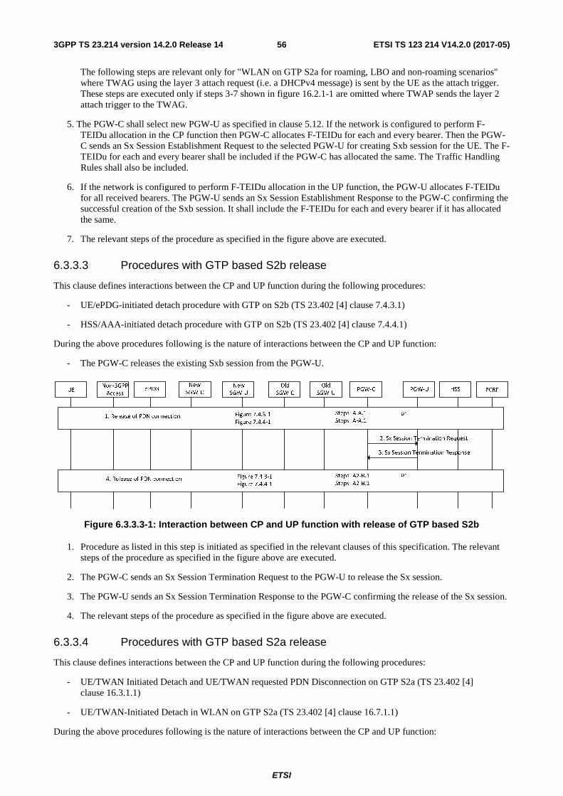
ETSI
ETSI TS 123 214 V14.2.0 (2017-05)563GPP TS 23.214 version 14.2.0 Release 14
The following steps are relevant only for "WLAN on GTP S2a for roaming, LBO and non-roaming scenarios" where TWAG using the layer 3 attach request (i.e. a DHCPv4 message) is sent by the UE as the attach trigger. These steps are executed only if steps 3-7 shown in figure 16.2.1-1 are omitted where TWAP sends the layer 2 attach trigger to the TWAG.
5. The PGW-C shall select new PGW-U as specified in clause 5.12. If the network is configured to perform F-TEIDu allocation in the CP function then PGW-C allocates F-TEIDu for each and every bearer. Then the PGW-C sends an Sx Session Establishment Request to the selected PGW-U for creating Sxb session for the UE. The F-TEIDu for each and every bearer shall be included if the PGW-C has allocated the same. The Traffic Handling Rules shall also be included.
6. If the network is configured to perform F-TEIDu allocation in the UP function, the PGW-U allocates F-TEIDu for all received bearers. The PGW-U sends an Sx Session Establishment Response to the PGW-C confirming the successful creation of the Sxb session. It shall include the F-TEIDu for each and every bearer if it has allocated the same.
7. The relevant steps of the procedure as specified in the figure above are executed.
6.3.3.3 Procedures with GTP based S2b release
This clause defines interactions between the CP and UP function during the following procedures:
- UE/ePDG-initiated detach procedure with GTP on S2b (TS 23.402 [4] clause 7.4.3.1)
- HSS/AAA-initiated detach procedure with GTP on S2b (TS 23.402 [4] clause 7.4.4.1)
During the above procedures following is the nature of interactions between the CP and UP function:
- The PGW-C releases the existing Sxb session from the PGW-U.
Figure 6.3.3.3-1: Interaction between CP and UP function with release of GTP based S2b
1. Procedure as listed in this step is initiated as specified in the relevant clauses of this specification. The relevant steps of the procedure as specified in the figure above are executed.
2. The PGW-C sends an Sx Session Termination Request to the PGW-U to release the Sx session.
3. The PGW-U sends an Sx Session Termination Response to the PGW-C confirming the release of the Sx session.
4. The relevant steps of the procedure as specified in the figure above are executed.
6.3.3.4 Procedures with GTP based S2a release
This clause defines interactions between the CP and UP function during the following procedures:
- UE/TWAN Initiated Detach and UE/TWAN requested PDN Disconnection on GTP S2a (TS 23.402 [4] clause 16.3.1.1)
- UE/TWAN-Initiated Detach in WLAN on GTP S2a (TS 23.402 [4] clause 16.7.1.1)
During the above procedures following is the nature of interactions between the CP and UP function:
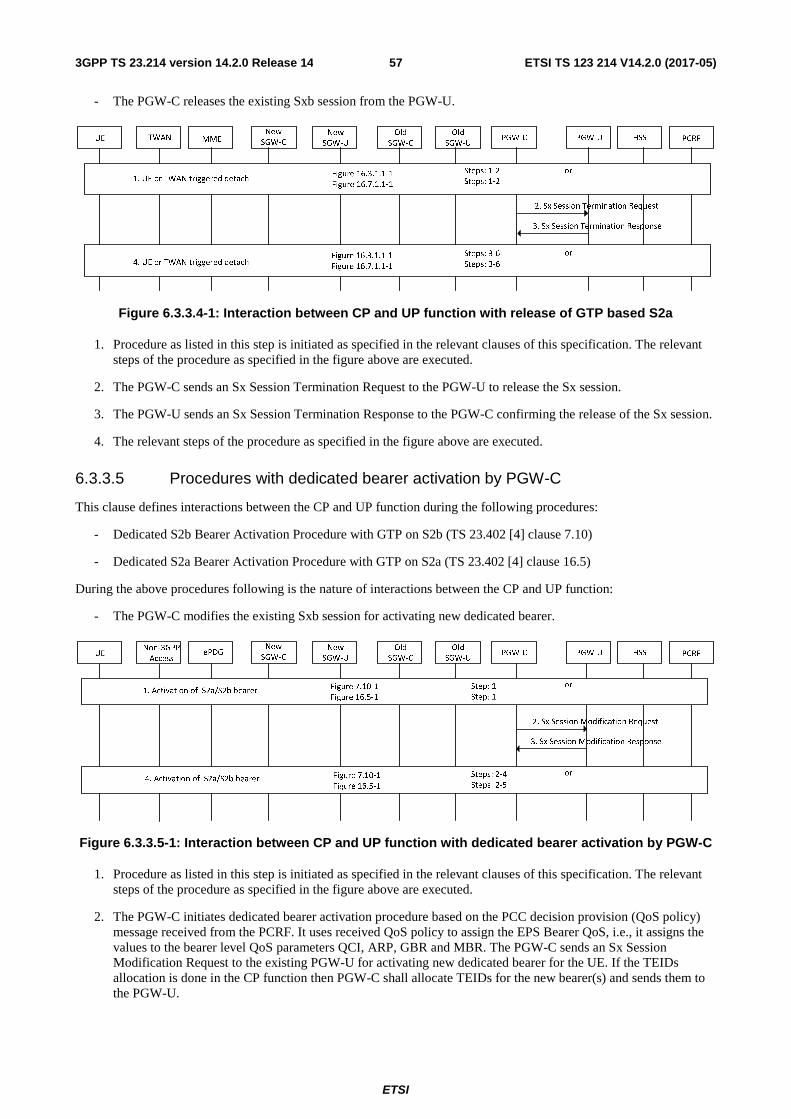
ETSI
ETSI TS 123 214 V14.2.0 (2017-05)573GPP TS 23.214 version 14.2.0 Release 14
- The PGW-C releases the existing Sxb session from the PGW-U.
Figure 6.3.3.4-1: Interaction between CP and UP function with release of GTP based S2a
1. Procedure as listed in this step is initiated as specified in the relevant clauses of this specification. The relevant steps of the procedure as specified in the figure above are executed.
2. The PGW-C sends an Sx Session Termination Request to the PGW-U to release the Sx session.
3. The PGW-U sends an Sx Session Termination Response to the PGW-C confirming the release of the Sx session.
4. The relevant steps of the procedure as specified in the figure above are executed.
6.3.3.5 Procedures with dedicated bearer activation by PGW-C
This clause defines interactions between the CP and UP function during the following procedures:
- Dedicated S2b Bearer Activation Procedure with GTP on S2b (TS 23.402 [4] clause 7.10)
- Dedicated S2a Bearer Activation Procedure with GTP on S2a (TS 23.402 [4] clause 16.5)
During the above procedures following is the nature of interactions between the CP and UP function:
- The PGW-C modifies the existing Sxb session for activating new dedicated bearer.
Figure 6.3.3.5-1: Interaction between CP and UP function with dedicated bearer activation by PGW-C
1. Procedure as listed in this step is initiated as specified in the relevant clauses of this specification. The relevant steps of the procedure as specified in the figure above are executed.
2. The PGW-C initiates dedicated bearer activation procedure based on the PCC decision provision (QoS policy) message received from the PCRF. It uses received QoS policy to assign the EPS Bearer QoS, i.e., it assigns the values to the bearer level QoS parameters QCI, ARP, GBR and MBR. The PGW-C sends an Sx Session Modification Request to the existing PGW-U for activating new dedicated bearer for the UE. If the TEIDs allocation is done in the CP function then PGW-C shall allocate TEIDs for the new bearer(s) and sends them to the PGW-U.
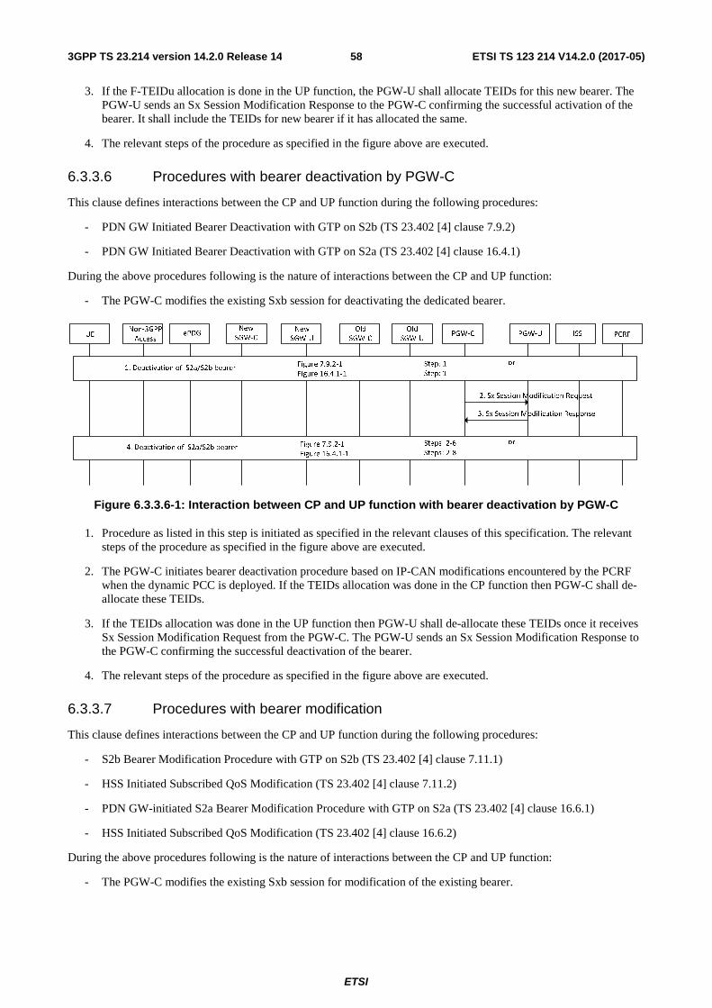
ETSI
ETSI TS 123 214 V14.2.0 (2017-05)583GPP TS 23.214 version 14.2.0 Release 14
3. If the F-TEIDu allocation is done in the UP function, the PGW-U shall allocate TEIDs for this new bearer. The PGW-U sends an Sx Session Modification Response to the PGW-C confirming the successful activation of the bearer. It shall include the TEIDs for new bearer if it has allocated the same.
4. The relevant steps of the procedure as specified in the figure above are executed.
6.3.3.6 Procedures with bearer deactivation by PGW-C
This clause defines interactions between the CP and UP function during the following procedures:
- PDN GW Initiated Bearer Deactivation with GTP on S2b (TS 23.402 [4] clause 7.9.2)
- PDN GW Initiated Bearer Deactivation with GTP on S2a (TS 23.402 [4] clause 16.4.1)
During the above procedures following is the nature of interactions between the CP and UP function:
- The PGW-C modifies the existing Sxb session for deactivating the dedicated bearer.
Figure 6.3.3.6-1: Interaction between CP and UP function with bearer deactivation by PGW-C
1. Procedure as listed in this step is initiated as specified in the relevant clauses of this specification. The relevant steps of the procedure as specified in the figure above are executed.
2. The PGW-C initiates bearer deactivation procedure based on IP-CAN modifications encountered by the PCRF when the dynamic PCC is deployed. If the TEIDs allocation was done in the CP function then PGW-C shall de-allocate these TEIDs.
3. If the TEIDs allocation was done in the UP function then PGW-U shall de-allocate these TEIDs once it receives Sx Session Modification Request from the PGW-C. The PGW-U sends an Sx Session Modification Response to the PGW-C confirming the successful deactivation of the bearer.
4. The relevant steps of the procedure as specified in the figure above are executed.
6.3.3.7 Procedures with bearer modification
This clause defines interactions between the CP and UP function during the following procedures:
- S2b Bearer Modification Procedure with GTP on S2b (TS 23.402 [4] clause 7.11.1)
- HSS Initiated Subscribed QoS Modification (TS 23.402 [4] clause 7.11.2)
- PDN GW-initiated S2a Bearer Modification Procedure with GTP on S2a (TS 23.402 [4] clause 16.6.1)
- HSS Initiated Subscribed QoS Modification (TS 23.402 [4] clause 16.6.2)
During the above procedures following is the nature of interactions between the CP and UP function:
- The PGW-C modifies the existing Sxb session for modification of the existing bearer.

ETSI
ETSI TS 123 214 V14.2.0 (2017-05)593GPP TS 23.214 version 14.2.0 Release 14
Figure 6.3.3.7-1: Interaction between CP and UP function with bearer modification
1. Procedure as listed in this step is initiated as specified in the relevant clauses of this specification. The relevant steps of the procedure as specified in the figure above are executed.
2. The PGW-C initiates dedicated bearer modification procedure based on the PCC decision provision (QoS policy) message received from the PCRF. It uses this QoS policy to determine that a service data flow shall be aggregated to or removed from an active bearer or that the authorized QoS of a service data flow has changed. The PGW-C sends an Sx Session Modification Request to the existing PGW-U for modification of the existing bearer for the UE.
3. The PGW-U updates the EPS Bearer QoS to match the traffic flow aggregate and sends an Sx Session Modification Response to the PGW-C confirming the successful modification of the bearer.
4. The relevant steps of the procedure as specified in the figure above are executed.
6.3.3.8 Procedures with handover from non-3GPP access
This clause defines interactions between the CP and UP function during the following procedures:
- Handover from Trusted or Untrusted Non-3GPP IP Access to E-UTRAN with PMIPv6 on S2a or S2b and GTP on S5/S8 interfaces (TS 23.402 [4] clause 8.2.1.1).
- Handover from Trusted/untrusted Non-3GPP IP Access to UTRAN/GERAN with PMIP on S2a and GTP based S5/S8 (TS 23.402 [4] clause 8.2.1.3).
- Handover from Untrusted Non-3GPP IP Access to E-UTRAN with GTP on S2b and GTP on S5/S8 interfaces (TS 23.402 [4] clause 8.6.1.1).
- Handover from Untrusted Non-3GPP IP Access to UTRAN/GERAN with GTP on S2b and GTP on S5/S8 interfaces (TS 23.402 [4] clause 8.6.1.2).
During the above procedures following is the nature of interactions between the CP and UP function:
- The new SGW-C selects a new SGW-U and creates Sxa session.
- The SGW-C modifies the existing Sxa session for modification of the bearer.
- The new PGW-C selects a new PGW-U and creates Sxb session.
- The PGW-C modifies the existing Sxb session for modification of the bearer.
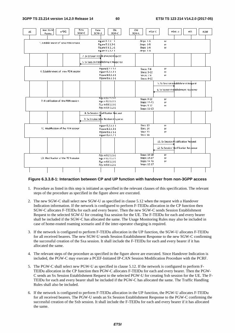
ETSI
ETSI TS 123 214 V14.2.0 (2017-05)603GPP TS 23.214 version 14.2.0 Release 14
Non-3GPP
AccessePDGUE
New
SGW-C
New
SGW-U
Old
SGW-C
Old
SGW-UPGW-C PGW-U HSS PCRF
5. Sx Session Establishment Request
6. Sx Session Establishment Response
1. Establishment of new PDN sessionFigure 8.2.1.1-1
Figure 8.2.1.3-1
Figure 8.6.1.1-1
Figure 8.6.1.2-1
Steps: 1-6
Steps: 1-8
Steps: 1-6
Steps: 1-8
7. Modification of the PDN sessionFigure 8.2.1.1-1
Figure 8.2.1.3-1
Figure 8.6.1.1-1
Figure 8.6.1.2-1
Steps: 9-12
Steps: 11-13
Steps: 9-12
Steps: 11-13
2. Sx Session Establishment Request
3. Sx Session Establishment Response
4. Establishment of new PDN sessionFigure 8.2.1.1-1
Figure 8.2.1.3-1
Figure 8.6.1.1-1
Figure 8.6.1.2-1
Steps: 7-8
Steps: 9-10
Steps: 7-8
Steps: 9-10
11. Sx Session Modification Request
12. Sx Session Modification Response
13. Modification of the PDN sessionFigure 8.2.1.1-1
Figure 8.2.1.3-1
Figure 8.6.1.1-1
Figure 8.6.1.2-1
Steps: 14-18
Steps: 15-17
Steps: 14-18
Steps: 15-17
8. Sx Session Modification Request
9. Sx Session Modification Response
10. Modification of the PDN sessionFigure 8.2.1.1-1
Figure 8.2.1.3-1
Figure 8.6.1.1-1
Figure 8.6.1.2-1
Step: 13
Step: 14
Step: 13
Step: 14
or
or
or
or
or
or
or
or
or
or
or
or
or
or
or
Figure 6.3.3.8-1: Interaction between CP and UP function with handover from non-3GPP access
1. Procedure as listed in this step is initiated as specified in the relevant clauses of this specification. The relevant steps of the procedure as specified in the figure above are executed.
2. The new SGW-C shall select new SGW-U as specified in clause 5.12 when the request with a Handover Indication information. If the network is configured to perform F-TEIDu allocation in the CP function then SGW-C allocates F-TEIDu for each and every bearer. Then the new SGW-C sends Session Establishment Request to the selected SGW-U for creating Sxa session for the UE. The F-TEIDu for each and every bearer shall be included if the SGW-C has allocated the same. The Usage Monitoring Rules may also be included in case of home-routed roaming scenario and if the inter-operator charging is required.
3. If the network is configured to perform F-TEIDu allocation in the UP function, the SGW-U allocates F-TEIDu for all received bearers. The new SGW-U sends Session Establishment Response to the new SGW-C confirming the successful creation of the Sxa session. It shall include the F-TEIDu for each and every bearer if it has allocated the same.
4. The relevant steps of the procedure as specified in the figure above are executed. Since Handover Indication is included, the PGW-C may execute a PCEF-Initiated IP-CAN Session Modification Procedure with the PCRF.
5. The PGW-C shall select new PGW-U as specified in clause 5.12. If the network is configured to perform F-TEIDu allocation in the CP function then PGW-C allocates F-TEIDu for each and every bearer. Then the PGW-C sends an Sx Session Establishment Request to the selected PGW-U for creating Sxb session for the UE. The F-TEIDu for each and every bearer shall be included if the PGW-C has allocated the same. The Traffic Handling Rules shall also be included.
6. If the network is configured to perform F-TEIDu allocation in the UP function, the PGW-U allocates F-TEIDu for all received bearers. The PGW-U sends an Sx Session Establishment Response to the PGW-C confirming the successful creation of the Sxb session. It shall include the F-TEIDu for each and every bearer if it has allocated the same.
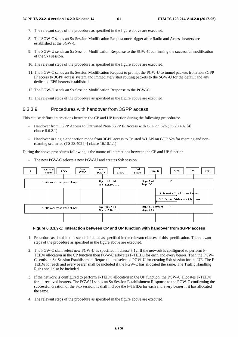
ETSI
ETSI TS 123 214 V14.2.0 (2017-05)613GPP TS 23.214 version 14.2.0 Release 14
7. The relevant steps of the procedure as specified in the figure above are executed.
8. The SGW-C sends an Sx Session Modification Request once trigger after Radio and Access bearers are established at the SGW-C.
9. The SGW-U sends an Sx Session Modification Response to the SGW-C confirming the successful modification of the Sxa session.
10. The relevant steps of the procedure as specified in the figure above are executed.
11. The PGW-C sends an Sx Session Modification Request to prompt the PGW-U to tunnel packets from non 3GPP IP access to 3GPP access system and immediately start routing packets to the SGW-U for the default and any dedicated EPS bearers established.
12. The PGW-U sends an Sx Session Modification Response to the PGW-C.
13. The relevant steps of the procedure as specified in the figure above are executed.
6.3.3.9 Procedures with handover from 3GPP access
This clause defines interactions between the CP and UP function during the following procedures:
- Handover from 3GPP Access to Untrusted Non-3GPP IP Access with GTP on S2b (TS 23.402 [4] clause 8.6.2.1)
- Handover in single-connection mode from 3GPP access to Trusted WLAN on GTP S2a for roaming and non-roaming scenarios (TS 23.402 [4] clause 16.10.1.1)
During the above procedures following is the nature of interactions between the CP and UP function:
- The new PGW-C selects a new PGW-U and creates Sxb session.
Figure 6.3.3.9-1: Interaction between CP and UP function with handover from 3GPP access
1. Procedure as listed in this step is initiated as specified in the relevant clauses of this specification. The relevant steps of the procedure as specified in the figure above are executed.
2. The PGW-C shall select new PGW-U as specified in clause 5.12. If the network is configured to perform F-TEIDu allocation in the CP function then PGW-C allocates F-TEIDu for each and every bearer. Then the PGW-C sends an Sx Session Establishment Request to the selected PGW-U for creating Sxb session for the UE. The F-TEIDu for each and every bearer shall be included if the PGW-C has allocated the same. The Traffic Handling Rules shall also be included.
3. If the network is configured to perform F-TEIDu allocation in the UP function, the PGW-U allocates F-TEIDu for all received bearers. The PGW-U sends an Sx Session Establishment Response to the PGW-C confirming the successful creation of the Sxb session. It shall include the F-TEIDu for each and every bearer if it has allocated the same.
4. The relevant steps of the procedure as specified in the figure above are executed.

ETSI
ETSI TS 123 214 V14.2.0 (2017-05)623GPP TS 23.214 version 14.2.0 Release 14
6.3.4 Updates to procedures specified in TS 23.060 [5]
6.3.4.1 Procedures with PDP context deletion
This clause defines interactions between the CP and UP function during the following procedures, if the procedure involves S4:
- Combined GPRS / IMSI Attach procedure.
- MS-Initiated Combined GPRS / IMSI Detach Procedure.
- SGSN-Initiated GPRS Detach Procedure.
- HLR-Initiated GPRS Detach Procedure.
- MS Initiated PDP Context Deactivation Procedure for A/Gb mode.
- MS Initiated PDP Context Deactivation Procedure for Iu mode.
- SGSN-initiated PDP Context Deactivation Procedure.
- GGSN-initiated PDP Context Deactivation Procedure.
During the above procedures involving S4, following is the nature of interactions between the CP and UP function:
- The SGW-C releases the existing Sxa session from SGW-U.
- The PGW-C releases the existing Sxb session from PGW-U.
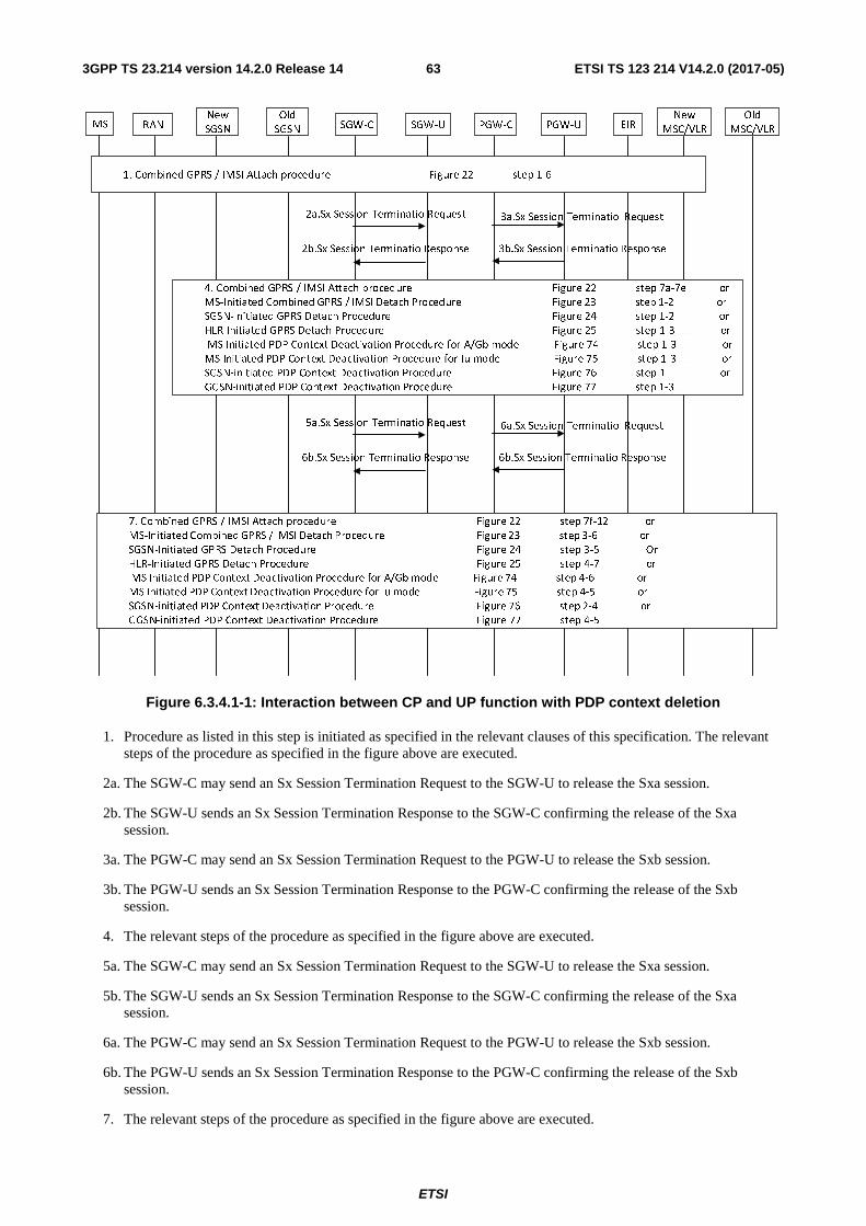
ETSI
ETSI TS 123 214 V14.2.0 (2017-05)633GPP TS 23.214 version 14.2.0 Release 14
MS RANNew
SGSN
Old
SGSN SGW-C SGW-U PGW-C PGW-U EIRNew
MSC/VLR
Old
MSC/VLR
1. Combined GPRS / IMSI Attach procedure Figure 22 step 1-6
7. Combined GPRS / IMSI Attach procedure Figure 22 step 7f-12 or
MS-Initiated Combined GPRS / IMSI Detach Procedure Figure 23 step 3-6 or
SGSN-Initiated GPRS Detach Procedure Figure 24 step 3-5 Or
HLR-Initiated GPRS Detach Procedure Figure 25 step 4-7 or
MS Initiated PDP Context Deactivation Procedure for A/Gb mode Figure 74 step 4-6 or
MS Initiated PDP Context Deactivation Procedure for Iu mode Figure 75 step 4-5 or
SGSN-initiated PDP Context Deactivation Procedure Figure 76 step 2-4 or
GGSN-initiated PDP Context Deactivation Procedure Figure 77 step 4-5
4. Combined GPRS / IMSI Attach procedure Figure 22 step 7a-7e or
MS-Initiated Combined GPRS / IMSI Detach Procedure Figure 23 step 1-2 or
SGSN-Initiated GPRS Detach Procedure Figure 24 step 1-2 or
HLR-Initiated GPRS Detach Procedure Figure 25 step 1-3 or
MS Initiated PDP Context Deactivation Procedure for A/Gb mode Figure 74 step 1-3 or
MS Initiated PDP Context Deactivation Procedure for Iu mode Figure 75 step 1-3 or
SGSN-initiated PDP Context Deactivation Procedure Figure 76 step 1 or
GGSN-initiated PDP Context Deactivation Procedure Figure 77 step 1-3
2a.Sx Session Terminatio Request 3a.Sx Session Terminatio Request
2b.Sx Session Terminatio Response 3b.Sx Session Terminatio Response
5a.Sx Session Terminatio Request 6a.Sx Session Terminatio Request
6b.Sx Session Terminatio Response 6b.Sx Session Terminatio Response
Figure 6.3.4.1-1: Interaction between CP and UP function with PDP context deletion
1. Procedure as listed in this step is initiated as specified in the relevant clauses of this specification. The relevant steps of the procedure as specified in the figure above are executed.
2a. The SGW-C may send an Sx Session Termination Request to the SGW-U to release the Sxa session.
2b. The SGW-U sends an Sx Session Termination Response to the SGW-C confirming the release of the Sxa session.
3a. The PGW-C may send an Sx Session Termination Request to the PGW-U to release the Sxb session.
3b. The PGW-U sends an Sx Session Termination Response to the PGW-C confirming the release of the Sxb session.
4. The relevant steps of the procedure as specified in the figure above are executed.
5a. The SGW-C may send an Sx Session Termination Request to the SGW-U to release the Sxa session.
5b. The SGW-U sends an Sx Session Termination Response to the SGW-C confirming the release of the Sxa session.
6a. The PGW-C may send an Sx Session Termination Request to the PGW-U to release the Sxb session.
6b. The PGW-U sends an Sx Session Termination Response to the PGW-C confirming the release of the Sxb session.
7. The relevant steps of the procedure as specified in the figure above are executed.

ETSI
ETSI TS 123 214 V14.2.0 (2017-05)643GPP TS 23.214 version 14.2.0 Release 14
6.3.4.2 Procedures with PDP context update
This clause defines interactions between the CP and UP function during the following procedures, if the procedure involves S4:
- Inter SGSN Routeing Area Update Procedure.
- Combined RA / LA Update in the Case of Inter SGSN RA Update Procedure.
- Iu mode RA Update Procedure.
- SRNS Relocation Procedure.
- Combined Hard Handover and SRNS Relocation Procedure.
- Combined Cell / URA Update and SRNS Relocation Procedure.
- Enhanced Serving RNS Relocation.
- MS Initiated Service Request Procedure using Gn/Gp.
- Network Initiated Service Request Procedure.
- Iu mode to A/Gb mode Intra SGSN Change.
- A/Gb mode to Iu mode Intra SGSN Change.
- Iu mode to A/Gb mode Inter-SGSN Change.
- A/Gb mode to Iu mode Inter SGSN Change.
- GPRS Paging Procedure (A/Gb mode).
- SGSN-Initiated PDP Context Modification Procedure, A/Gb mode.
- SGSN-Initiated PDP Context Modification Procedure, Iu mode.
- Request part of SGSN-Initiated EPS Bearer Modification Procedure using S4.
- GGSN-Initiated PDP Context Modification Procedure, A/Gb mode.
- GGSN-Initiated PDP Context Modification Procedure, Iu mode.
- MS-Initiated PDP Context Modification Procedure, A/Gb mode.
- MS-Initiated PDP Context Modification Procedure, Iu mode.
During the above procedures involving S4, following is the nature of interactions between the CP and UP function:
- The SGW-C informs the SGW-U to modify the Sxa session.
- The PGW-C informs the PGW-U to modify the Sxb session.

ETSI
ETSI TS 123 214 V14.2.0 (2017-05)653GPP TS 23.214 version 14.2.0 Release 14
MS RANNew
SGSN
Old
SGSN SGW-C SGW-U PGW-C PGW-U EIRNew
MSC/VLR
Old
MSC/VLR
1. Inter SGSN Routeing Area Update Procedure Figure 33 step 1-6 or
Combined RA / LA Update in the Case of Inter SGSN RA Update Procedure Figure 35 step 1-6 or
Iu mode RA Update Procedure Figure 36 step 1-9 or
SRNS Relocation Procedure Figure 39 step 1-13 or
Combined Hard Handover and SRNS Relocation Procedure Figure 42 step 1-13 or
Combined Cell / URA Update and SRNS Relocation Procedure Figure 43 step 1-13 or
Enhanced Serving RNS Relocation Figure 44a2 step 1-3 or
MS Initiated Service Request Procedure using Gn/Gp Figure50 step 1-7 or
Network Initiated Service Request Procedure Figure51 step 1-7 or
Iu mode to A/Gb mode Intra SGSN Change Figure52 step 1-6 or
A/Gb mode to Iu mode Intra SGSN Change Figure53 step 1-11 or
Iu mode to A/Gb mode Inter-SGSN Change Figure54 step 1-10 or
A/Gb mode to Iu mode Inter SGSN Change Figure55 step 1-8 or
GPRS Paging Procedure (A/Gb mode) Figure56 step 1-5 or
SGSN-Initiated PDP Context Modification Procedure, A/Gb mode Figure70a step 1-2 or 1-5 or
SGSN-Initiated PDP Context Modification Procedure, Iu mode Figure70b step 1-2 or 1-5 or
Request part of SGSN-Initiated EPS Bearer Modification Procedure using S4 Figure70c step 1-2 or 1-5 or
GGSN-Initiated PDP Context Modification Procedure, A/Gb mode Figure71a step 1-6 or
GGSN-Initiated PDP Context Modification Procedure, Iu mode Figure71b step 1-6 or
MS-Initiated PDP Context Modification Procedure, A/Gb mode Figure72a step 1-3 or 1-6 or
MS-Initiated PDP Context Modification Procedure, Iu mode Figure72b step 1-3 or 1-6
4.Inter SGSN Routeing Area Update Procedure Figure 33 step 7-12 or
Combined RA / LA Update in the Case of Inter SGSN RA Update Procedure Figure 35 step 7-16 or
Iu mode RA Update Procedure Figure 36 step 10-20 or
SRNS Relocation Procedure Figure 39 step 14-15 or
Combined Hard Handover and SRNS Relocation Procedure Figure 42 step 14-15 or
Combined Cell / URA Update and SRNS Relocation Procedure Figure 43 step 14-15 or
Enhanced Serving RNS Relocation Figure 44a2 step 4-6 or
MS Initiated Service Request Procedure using Gn/Gp Figure50 step 8 or
Network Initiated Service Request Procedure Figure51 step 8 or
Iu mode to A/Gb mode Intra SGSN Change Figure52 step 7-15 or
A/Gb mode to Iu mode Intra SGSN Change Figure53 step 12-13 or
Iu mode to A/Gb mode Inter-SGSN Change Figure54 step 11-22 or
A/Gb mode to Iu mode Inter SGSN Change Figure55 step 9-20a or
SGSN-Initiated PDP Context Modification Procedure, A/Gb mode Figure70a step 3-8 or 6-8 or
SGSN-Initiated PDP Context Modification Procedure, Iu mode Figure70b step 3-8 or 6-8 or
MS-Initiated PDP Context Modification Procedure, A/Gb mode Figure72a step 4-7 or 7 or
MS-Initiated PDP Context Modification Procedure, Iu mode Figure72b step 4-7 or 7
2a.Sx Session Modification Request 3a.Sx Session Modification Request
2b.Sx Session Modification Response 3b.Sx Session Modification Response
Figure 6.3.4.2-1: Interaction between CP and UP function with PDP context update
1. Procedure as listed in this step is initiated as specified in the relevant clauses of this specification. The relevant steps of the procedure as specified in the figure above are executed.
2a. The SGW-C may send an Sx Session Modification Request to the SGW-U to update the Sxa session.
2b. The SGW-U sends an Sx Session Modification Response to the SGW-C confirming the update the Sxa session.
3a. The PGW-C may send an Sx Session Modification Request to the PGW-U to update the Sxb session.
3b. The PGW-U sends an Sx Session Modification Response to the PGW-C confirming the update the Sxb session.
4. The relevant steps of the procedure as specified in the figure above are executed.
6.3.4.3 Procedures with PDP context creation
This clause defines interactions between the CP and UP function during the following procedures, if the procedure involves S4:

ETSI
ETSI TS 123 214 V14.2.0 (2017-05)663GPP TS 23.214 version 14.2.0 Release 14
- IPv6 Stateless Address Autoconfiguration Procedure.
- PDP Context Activation Procedure for A/Gb mode.
- PDP Context Activation Procedure for Iu mode.
- Secondary PDP Context Activation Procedure for A/Gb mode.
- Secondary PDP Context Activation Procedure for Iu mode.
During the procedures involving S4 listed above, following is the nature of interactions between the CP and UP function:
- The SGW-C informs the SGW-U to create the Sxa session.
- The PGW-C informs the PGW-U to create the Sxb session.
- The SGW-C informs the SGW-U to modify the Sxa session.
- The PGW-C informs the PGW-U to modify the Sxb session.
MS BSS SGSN SGW-C SGW-U PGW-C PGW-U
1. IPv6 Stateless Address Autoconfiguration Procedure Figure 62 step 1-2 or
PDP Context Activation Procedure for A/Gb mode Figure 63 step 1-4 or
PDP Context Activation Procedure for Iu mode Figure 64 step 1-4 or
Secondary PDP Context Activation Procedure for A/Gb mode Figure 65 step 1-3 or
Secondary PDP Context Activation Procedure for Iu mode Figure 66 step 1-3
2a.Sx Session Establishment Request 3a.Sx Session Establishment Request
2b.Sx Session Establishment Response 3b.Sx Session Establishment Response
4.IPv6 Stateless Address Autoconfiguration Procedure Figure 62 step 3-5 or
PDP Context Activation Procedure for A/Gb mode Figure 63 step 7-8 or
PDP Context Activation Procedure for Iu mode Figure 64 step 5-8 or
Secondary PDP Context Activation Procedure for A/Gb mode Figure 65 step 5-6 or
Secondary PDP Context Activation Procedure for Iu mode Figure 66 step 4,6
7. PDP Context Activation Procedure for A/Gb mode Figure 63 step 9 or
PDP Context Activation Procedure for Iu mode Figure 64 step 9 or
Secondary PDP Context Activation Procedure for A/Gb mode Figure 65 step 7 or
Secondary PDP Context Activation Procedure for Iu mode Figure 66 step 7
5a.Sx Session Modification Request 6a.Sx Session Modification Request
5b.Sx Session Modification Response 6b.Sx Session Modification Response
RAN
Figure 6.3.4.3-1: Interaction between CP and UP function with PDP context creation
1. Procedure as listed in this step is initiated as specified in the relevant clauses of this specification. The relevant steps of the procedure as specified in the figure above are executed.
2a. The SGW-C may send an Sx Session Modification Request to the SGW-U to create the Sxa session.
2b. The SGW-U sends an Sx Session Modification Response to the SGW-C confirming the Sxa session creation.
3a. The PGW-C may send an Sx Session Modification Request to the PGW-U to create the Sxb session.
3b. The PGW-U sends an Sx Session Modification Response to the PGW-C confirming the Sxb session creation.
4. The relevant steps of the procedure as specified in the figure above are executed.

ETSI
ETSI TS 123 214 V14.2.0 (2017-05)673GPP TS 23.214 version 14.2.0 Release 14
5a. The SGW-C may send an Sx Session Modification Request to the SGW-U to update the Sxa session.
5b. The SGW-U sends an Sx Session Modification Response to the SGW-C confirming the Sxa session update.
6a. The PGW-C may send an Sx Session Modification Request to the PGW-U to update the Sxb session.
6b. The PGW-U sends an Sx Session Modification Response to the PGW-C confirming the Sxb session update.
7. The relevant steps of the procedure as specified in the figure above are executed.
6.4 Sx Reporting Procedures
6.4.1 General
The Sx reporting procedure is used by the UP function of SGW, PGW or TDF to report events to the CP function.
The following Sx reporting procedures exist: Sx session level reporting and Sx node level reporting. Both are initiated by the CP function.
6.4.2 Sx Session Level Reporting Procedure
This procedure is used by the UP function to report events related to an Sx session for an individual PDN connection IP-CAN session, TDF session or TDF in unsolicited reporting mode. The triggers for event reporting were configured on the UP function during Sx session management procedures by the CP function (excluding the Sx session termination procedure).
UP function
2. Sx Report
CP function
3. Sx Report ACK
1. Trigger to report event
Figure 6.4.2-1: Sx Session Level Reporting procedure
1. The UP function detects that an event has to be reported. The reporting triggers involve the following cases:
(1) Usage report (by SGW-U, PGW-U and TDF-U).
Usage information shall be collected in the UP function and reported to the CP function as defined in clause 5.3 and clause 7.4.
(2) Start of traffic detection (by PGW-U and TDF-U).
When traffic detection is requested by PGW-C/TDF-C, and the start of traffic is detected for a PDR, the PGW-U/TDF-U shall report the start of traffic detection to the PGW-C/TDF-C and indicate the PDR rule ID.
(3) Stop of traffic detection (by PGW-U and TDF-U).
When traffic detection is requested by PGW-C/TDF-C, and the end of traffic is detected for a PDR, the PGW-U/TDF-U shall report the stop of traffic detection to the PGW-C/TDF-C and indicate the PDR rule ID.
(4) Detection of 1st Downlink Data for Idle-Mode UE (by SGW-U)
When SGW-U receives the downlink packet but no S1-bearer for transmission and the buffering is performed by SGW-U, it shall report the detection of 1st downlink data to SGW-C, for the purpose of paging the UE.

ETSI
ETSI TS 123 214 V14.2.0 (2017-05)683GPP TS 23.214 version 14.2.0 Release 14
SGW-U shall also report the DSCP of the packet when instructed by SGW-C (e.g. in case the Paging Policy Differentiation function as described in TS 23.401 [2] is enabled at the SGW-C).
2. The UP function sends an Sx report message (list of [Reporting trigger, Measurement information]) to the CP function.
The Reporting trigger parameter contains the name of the event which triggered the report and the Measurement information parameter contains the actual information the CP function requested to be informed about.
3. The CP function responds with an Sx report ACK message.
6.5 Sx Management Procedures
6.5.1 General
Sx management procedures are used by the CP function to manage the UP function independent of any Sx session.
Editor's note: Currently it only includes Sx PFD management Procedure, and more procedures will be added after stage 3 finalize the work on Sx management procedures.
6.5.2 Sx PFD management Procedure
The Sx PFD management procedure is used by the PGW-C or TDF-C to provision/update/remove PFD(s) to the UP function independent of any Sx session.
The Sx PFD management procedure is a node level procedure, triggered by the interaction between the CP function and the PFDF for PFD retrieval ("Pull mode") or Management of PFD ("Push Mode").
PGW-C / TDF-C
1. PFD retrieval (“Pull mode”) or Management of PFD (“Push mode”)
PGW-U / TDF-U
2. PFD management request
3. PFD management response
Figure 6.5.2-1: Sx PFD Management Procedure
1. Upon any interaction between the CP function and the PFDF for PFD retrieval ("Pull mode") or Management of PFD ("Push Mode"), as is defined in TS 23.203 [3], the PFD(s) cached in the CP function is provisioned/updated/removed.
2. The CP function sends PFD management request to the UP function to provision/update/remove the PFD (s) corresponding to the Application ID(s).
3. The UP function acknowledges by responding with PFD management response message.

ETSI
ETSI TS 123 214 V14.2.0 (2017-05)693GPP TS 23.214 version 14.2.0 Release 14
7 Parameters
7.1 Parameters for Sx session management These parameters are used to control the functionality of the UP function related to an individual PDN connection, IP-CAN session, TDF session or TDF in unsolicited reporting mode as well as to inform about events occurring at the UP function. As the functionality of the respective UP functions differs, most parameters are specific to one or two of the reference points Sxa (between SGW-C and SGW-U), Sxb (PGW-C and PGW-U) and Sxc (TDF-C and TDF-U).
The Sx session management procedures however will use the relevant parameters in the same way for all Sx reference points: the Sx session establishment procedure as well as the Sx session modification procedure provide the control parameters to the UP function, the Sx session termination procedure removes all control parameters related to an Sx session and the Sx session level reporting procedure informs the CP function about events related to the Sx session that are detected by the UP function.
The parameters over Sx provided from CP function to UP function are grouped into session related parameters and four different rules, one "detection" rule and three different "enforcement" rules:
- Packet Detection Rule (PDR), with information describing what packets should receive a certain treatment (e.g. forwarding and other types of enforcement).
- Forwarding Action Rule (FAR), contains information on whether forwarding, dropping or buffering is to be applied to a packet.
- Usage Reporting Rule (URR), contains information that defines a certain measurement and how it shall be reported.
- QoS Enforcement Rule (QER), contains information related to QoS enforcement of traffic.
The UP function provides parameters over Sx to the CP function sending a Usage Report.
7.2 Session context The session context comprises the session related parameters and all PDRs, URRs, QERs and FARs with the same Session ID.
The following table describes the session related parameters provided over Sx.
Table 7.2-1: Session related parameters
Attribute Description Comment Applicability SGW
PDN
GW
TDF
Session ID Uniquely identifies a session.
This session corresponds to a PDN connection for SGW, a PDN connection and an IP-CAN session for PGW, TDF session for TDF or a TDF in unsolicited reporting mode.
X X X
Editor's note: If the above attributes cover everything or more attributes are needed is FFS.
7.3 Packet Detection Rule The following table describes the Packet Detection Rule (PDR) containing information required to classify a packet arriving at the UP function. There is at least one PDR per direction, e.g. UL direction or DL direction.

ETSI
ETSI TS 123 214 V14.2.0 (2017-05)703GPP TS 23.214 version 14.2.0 Release 14
Table 7.3-1: Attributes within Packet Detection Rule

ETSI
ETSI TS 123 214 V14.2.0 (2017-05)713GPP TS 23.214 version 14.2.0 Release 14
Attribute Description Comment Applicability SGW
PDN
GW
TDF
Session ID Identifies the session associated to this PDR
X X X
Rule ID Unique identifier to identify this information.
X X X
Precedence Determines the order, in which the detection information of all rules is applied
X X
Packet Detection information
Source interface
Contains the values "access side", "core side", "CP function" or "SGi-LAN".
Identifies whether the rule applies to incoming packets from the access side (i.e. up-link), the core side (i.e. down-link), the CP function (the packet from CP function) or the SGi-LAN side (the packet has experienced SGi-LAN Service Functions).
UE IP address
One IPv4 address and/or one IPv6 prefix with prefix length
Combination of UE IP address (together with PDN instance, if necessary), F-TEID, SDF filters, application ID for traffic detection: SGW UL: Local F-TEID SGW DL: Local F-TEID PGW UL: Local F-TEID + UE IP address + SDF/applicat.ID PGW DL: UE IP address + SDF/application ID TDF UL (solicited mode): UE IP address + SDF/application ID TDF DL (solicited mode): UE IP address + SDF/application ID TDF UL/DL (unsolicited mode): application ID
X X
PDN instance
Identifies the PDN instance associated with the incoming packet. Needed e.g. in case one UP function supports multiple APN with overlapping IP addresses.
X
X X
Local F-TEID
X X
SDF Filter X X Application ID
X X
Instructs the UP function to remove one or more outer header(s) (e.g. IP+UDP+GTP) from the incoming packet.
Any extension header shall be stored for this packet.
X
Outer header removal Every Forwarding action Rule ID identifies a forwarding action that has to be applied to a packet matching this rule.
X X X

ETSI
ETSI TS 123 214 V14.2.0 (2017-05)723GPP TS 23.214 version 14.2.0 Release 14
List of Forwarding Action Rule ID(s)
Every Reporting Rule ID identifies a measurement action that has to be applied to a packet matching this rule.
X X X
List of Reporting Rule ID(s) Every QoS Enforcement Rule ID identifies a QoS enforcement action that has to be applied to a packet matching this rule.
X X
Editor's note: If the above attributes cover everything or more attributes are needed is FFS.
7.4 Usage Reporting Rule The following table describes the Usage Reporting Rule (URR) that defines how a packet shall be accounted as well as when and how to report the measurements.
Table 7.4-1: Attributes within Usage Reporting Rule
Attribute Description Comment Applicability SGW
PDN
GW
TDF
Session ID Identifies the session associated to this URR
X X X
Measurement Key
Unique identifier of this Usage Reporting Rule. The CP function uses the measurement key to group flows that share a common measurement
This allows generation of measurements for flow based charging, flow based usage monitoring, bearer based monitoring and session based usage monitoring.
X X X
Active/Inactive Determines if measurement shall be performed (active), or if measurement shall be paused (inactive).
This is used with the Pause of Charging described in clause 5.3.4.
X
Reporting triggers
One or multiple of the events can be activated for the generation and reporting of the usage report.
Applicable events include: Start/stop of traffic detection with/without application instance identifier and deduced SDF filter reporting; Deletion of last rule for measurement key; Periodic measurement threshold reached; Volume/Time/Event measurement threshold reached; Immediate report requested; Measurement of incoming UL traffic; Measurement of discarded DL traffic.
X X X
Periodic measurement threshold
Defines the point in time for sending a periodic report for this measurement key (e.g. timeofday)
This allows generation of periodic usage report for e.g. offline charging. It can also be used for realizing the Monitoring time of the usage monitoring feature. It can also be used for realizing the Quota-Idle-Timeout, i.e. to enable the CP function to check whether any traffic has passed during this time.
X X X
Volume measurement threshold
Value in terms of uplink and/or downlink and/or total byte-count when the measurement report is to be generated.
X X X

ETSI
ETSI TS 123 214 V14.2.0 (2017-05)733GPP TS 23.214 version 14.2.0 Release 14
Editor's note: If the above attributes cover everything or more attributes are needed is FFS.
7.5 Forwarding Action Rule The following table describes the Forwarding Action Rule (FAR) that defines how a packet shall be forwarded, including packet encapsulation/decapsulation and forwarding destination.
Table 7.5-1: Attributes within Forwarding Action Rule
Attribute Description Comment Applicability SGW
PDN GW
TDF
Session ID Identifies the session associated to this FAR
X X X
Rule ID Unique identifier to identify this information.
X X X
Precedence Determines the order in which the Forwarding Action Rules are to be applied
X X X
PDN instance Identifies the PDN instance associated with the outgoing packet. Needed e.g. in case one UP function supports multiple APN with overlapping IP addresses.
X X
Destination interface Contains the values "access side", "core side", "CP function", or "SGi-LAN".
Identifies the interface for outgoing packets towards the access side (i.e. down-link), the core side (i.e. up-link), the CP function side (i.e. towards CP function) or the SGi-LAN side (i.e. towards SGi-LAN).
X X X
Outer header creation Instructs the UP function to add an outer header (IP+UDP+GTP) to the outgoing packet
Contains the F-TEIDu of peer entity (e.g. eNB, SGW, PGW, CP function). Any extension header stored for this packet shall be added.
X X
Send end marker packet(s)
Instructs the UP function to construct end marker packet(s) and send them out as described in clause 5.8.1.
This parameter should be sent together with the "out header creation" parameter of the new F-TEID-u.
X X
Time measurement threshold
Value in terms of the time duration (e.g. in seconds) when the measurement report is to be generated.
X X X
Event measurement threshold
Number of events (identified according to a locally configured policy) after which the measurement report is to be generated.
X X
Inactivity detection time
Defines the period of time after which the time measurement shall stop, if no packets are received.
Timer corresponding to this duration is restarted at the end of each transmitted packet.
X X
Event based reporting
Points to a locally configured policy which is identifies event(s) trigger for generating usage report.
X X

ETSI
ETSI TS 123 214 V14.2.0 (2017-05)743GPP TS 23.214 version 14.2.0 Release 14
Transport level marking
Transport level packet marking in the uplink and downlink, e.g. setting the DiffServ Code Point.
X X
Forwarding policy Reference to a preconfigured traffic forwarding treatment for FMSS or http redirection (NOTE 1)
Contains TSP ID or Redirect Destination and values for the forwarding behaviour (always, after measurement report (for termination action "redirect"))
X X
Container for header enrichment
Contains information to be used by the UP function for header enrichment
Only relevant for the uplink direction
X X
Delay Downlink Packet Notification Information
D parameter See clause 5.9.3 X
Extended buffering Information
DL Data Buffer Expiration Time
See clause 5.9.3 X
DL Suggested Packet Count
See clause 5.9.3
NOTE 1: The TSP ID action is enforced before the Outer header creation actions.
Editor's note: Additional forwarding actions (encapsulation formats) may be needed depending on CT4 conclusions, e.g. to support forwarding between UP function and CP function.
7.6 QoS Enforcement Rule The following table describes the QoS Enforcement Rule (QER) that defines how a packet shall be treated in terms of bit rate limitation and packet marking for QoS purposes. All Packet Detection Rules that refer to the same QER share the same QoS resources, e.g. MBR.

ETSI
ETSI TS 123 214 V14.2.0 (2017-05)753GPP TS 23.214 version 14.2.0 Release 14
Table 7.6-1: Attributes within QoS Enforcement Rule
Attribute Description Comment Applicability SGW
PDN GW
TDF
Session ID Identifies the session associated to this QER
X X X
Rule ID Unique identifier to identify this information.
X X X
Precedence Determines the order in which the QoS Enforcement Rules are to be applied
X X X
QoS Enforcement Rule correlation ID
An identity allowing the UP function to correlate multiple Sessions for the same UE and APN.
Is used to correlate QoS Enforcement Rules for APN-AMBR enforcement
X
Gate status UL/DL
Instructs the UP function to let the flow pass or to block the flow
Values are: open, close, close after measurement report (for termination action "discard")
X X
Maximum bitrate
The uplink/downlink maximum bitrate to be enforced for the packets.
This field may e.g. contain any one of: - APN-AMBR (for a QER that is referenced by all relevant Packet Detection Rules of all PDN Connections to an APN) - TDF session MBR (for a QER that is referenced by all Packet Detection Rules of a TDF Session) - bearer MBR (for a QER that is referenced by all Packet Detection Rules of a bearer) - SDF MBR (for a QER that is referenced by the uplink/downlink Packet Detection Rule of a SDF)
X X
Guaranteed bitrate
The uplink/downlink guaranteed bitrate authorized for the packets.
This field contains: - bearer GBR (for a QER that is referenced by all Packet Detection Rules of a bearer)
X X
Down-link flow level marking
Flow level packet marking in the downlink.
For PGW, this is for controlling the SCI marking in the GTP extension header (for service indication towards GERAN as described in TS 23.060 [5]). For TDF, this is for controlling the DSCP marking for application indication.
X X
Packet rate Number of packets per time interval to be enforced.
This field contains any one of: - downlink packet rate for Serving PLMN Rate Control (the QER is referenced by all PDRs of the UE belonging to PDN connections using CIoT EPS Optimizations as described in TS 23.401 [2]) - uplink/downlink packet rate for APN Rate Control (the QER is referenced by all PDRs of the UE belonging to PDN connections to the same APN using CIoT EPS Optimizations as described in TS 23.401 [2]).
X
Editor's note: If the above attributes cover everything or more attributes are needed is FFS.

ETSI
ETSI TS 123 214 V14.2.0 (2017-05)763GPP TS 23.214 version 14.2.0 Release 14
7.7 Usage Report generated by UP function The UP function sends the usage report to inform the CP function about the measurement of an active URR or about the detection of application traffic of an active Packet Detection Rule. For each URR, the usage report may be generated repeatedly, i.e. as long as any one of the valid event triggers applies. A final usage report is sent for a URR when it is no longer active, i.e. either the URR is removed or all the references to this URR in any of the Packet Detection Rules belonging to the Sx session.
Following attributes can be included in the usage report:

ETSI
ETSI TS 123 214 V14.2.0 (2017-05)773GPP TS 23.214 version 14.2.0 Release 14
Table 7.7-1: Attributes within Usage Report
Attribute Description Comment Applicability SGW
PDN GW
TDF
Session ID Uniquely identifies a session.
This corresponds to a PDN connection for SGW and PGW or a TDF session for TDF
X X X
Rule ID Uniquely identifies the Packet Detection Rule within a session which triggered the report
Only required when Reporting trigger is Detection of 1st DL packet on bearer (SGW) or Start/stop of traffic detection (PGW/TDF)
X X X
Measurement Key
Uniquely identifies the Measurement Key related to the report
Not sent when Reporting trigger is Start/stop of traffic detection
X X X
Reporting trigger
Identifies the trigger for the usage report.
Applicable values are: Detection of 1st DL packet on bearer (only for SGW); Start/stop of traffic detection with/without application instance identifier and deduced SDF filter reporting (only for PGW and TDF); Deletion of last rule for measurement key; Periodic measurement threshold reached; Volume/Time/Event measurement threshold reached; Immediate report requested; Measurement of incoming UL traffic (only for PGW); Measurement of discarded DL traffic (only for SGW).
X X X
Start time Provides the timestamp, in terms of absolute time, when the collection of the information provided within Usage-Information is started.
Not sent when Reporting trigger is Start/stop of traffic detection
X X X
End time Provides the timestamp, in terms of absolute time, when the information provided within Usage-Information is generated.
Not sent when Reporting trigger is Start/stop of traffic detection
X X X
Measurement information
Defines the measured volume/time/events for this measurement key
Contains DSCP of received packet when Reporting trigger is Detection of 1st DL packet on bearer (as described in TS 23.401 [2]) Contains application instance identifier and deduced SDF filter when Reporting trigger is Start/stop of traffic detection with application instance identifier and deduced SDF filter reporting (including deduced UE IP address for TDF in unsolicited mode) Not sent when Reporting trigger is Start/stop of traffic detection without application instance identifier and deduced SDF filter reporting
X X X
Time of last packet
Provides the timestamp, in terms of absolute time, when the last packet was received for this measurement key.
Enables the realization of Quota-Idle-Timeout, i.e. enable the CP function to adjust the Periodic measurement threshold. Not sent when Reporting trigger is Start/stop of traffic detection
X X
Editor's note: If the above attributes cover everything or more attributes are needed is FFS.

ETSI
ETSI TS 123 214 V14.2.0 (2017-05)783GPP TS 23.214 version 14.2.0 Release 14
7.8 Functional description
7.8.1 General
This clause describes how the CP function provides information over Sx to realize forwarding, reporting etc on different aggregation levels.
7.8.2 PDN connection and TDF session level context
The PDN connection or TDF session level context is realized over Sx by generating a Usage Reporting Rule and a QoS Enforcement Rule.
To apply PDN Connection or TDF session level reporting and MBR enforcement, the CP function provides over Sx:
- A URR that describes the reporting requirement for the PDN Connection or TDF session.
- A QER that describes the QoS enforcement actions that apply, i.e. a QER with APN-AMBR value (in case of PGW) or a QER with TDF session MBR (in case of TDF).
For session level reporting, the CP function includes references to the URR (i.e. URR Rule ID) in each Packet Detection Rule activated for the PDN Connection or TDF session. In case of PDN Connection or TDF session level usage monitoring where some SDF(s) are excluded, the CP function only includes a reference to the URR in those Packet Detection Rules that shall be included in the report.
For APN-AMBR policing, the CP function includes references (Rule ID) to the QER containing the APN-AMBR value in each Packet Detection Rule for non GBR traffic activated for the PDN Connection. The CP function shall apply the same QER for all Packet Detection Rules for non GBR traffic associated with any of the active PDN Connections of the same APN.
For TDF session MBR policing, the CP function includes references (Rule ID) to the QER containing the TDF session MBR value in each Packet Detection Rule activated for the TDF session.
7.8.3 Bearer related context
The bearer context is realized over Sx by generating one or two Forwarding Action Rules, a Usage Reporting Rule and a QoS Enforcement Rule that correspond to the bearer. In particular, the CP function may provide to the UP function for each active bearer:
- A Usage Reporting Rule that describes the reporting requirement for the bearer, including reporting events, measurement type etc for the bearer reports
- A QoS Enforcement Rule that describe the QoS enforcement actions that apply to the bearer, including the bearer MBR.
- Forwarding Action Rules describe the forwarding behaviour for the bearer. One Forwarding Action Rule is required for the downlink direction (in case of PGW or SGW) and one for the uplink direction (in case of SGW).
NOTE: The CP function maintains the association between the EPS Bearer ID and the rules on Sx corresponding to bearer level enforcement and reports. There is no need to provide a Bearer ID to the UP function.
The CP function associates, based on the bearer binding decisions, every Packet Detection Rule that is activated for a bearer with the URR, QER and FARs applicable for the this bearer by including references (Rule IDs) in the PDR:
- For bearer level reporting, the CP function includes a reference (Rule ID) to the URR for the bearer.
- For bearer level policing, the CP function includes a reference (Rule ID) to the QER for the bearer.
- For forwarding of packets over a bearer (GTP-U encapsulation), the CP function includes a reference (Rule ID) to the FAR the bearer. This is done per direction (UL and DL).

ETSI
ETSI TS 123 214 V14.2.0 (2017-05)793GPP TS 23.214 version 14.2.0 Release 14
7.8.4 Measurement key related context
The CP function provides a Usage Reporting Rule for each usage report that needs to be provided by the UP function. The CP function maintains a mapping between the Charging Key and/or Monitoring Key applicable for a SDF and the Measurement Key of the URR provided over Sx. For example, the CP function may provide one URR for each Charging Key and one URR for each Monitoring Key or may decide to provide a single URR for a Charging Key and a Monitoring Key in case there is complete overlap in the measurement requirements. Other mappings are also possible as determined by the CP function and is not limited by the standard as long as the reporting requirements from the CP function towards the OFCS/OCS and PCRF are fulfilled.
To associate traffic covered by a Packet Detection Rule with one or more measurement keys on Sx, the CP function includes in the Packet Detection Rule a reference to each URR (Rule ID) that is applicable for the traffic covered by the PDR.
7.9 Parameters for Sx management
7.9.1 Parameters for PFD management
The PGW-C/TDF-C can provide the PFD (s) to the applicable PGW-U/TDF-U for the enforcement independent of the Sx session. The management (provision/update/remove) of multiple PFD(s) from the PGW-C/TDF-C to the PGW-U/TDF-U can be handled at the same time.
Table 7.9-1: Attributes within PFD management message
Attribute Description Comment Applicability SGW
PDN
GW
TDF
PFD(s) Extension to the application detection filter
The presence of the PFD means the provision/update of the PFD(s) corresponding to the Application ID; The absence of the PFD means the removal of the PFD(s) corresponding to the Application ID
X X
Application ID Application idendifier which the PFD(s) is associated with
X X

ETSI
ETSI TS 123 214 V14.2.0 (2017-05)803GPP TS 23.214 version 14.2.0 Release 14
Annex A (informative): Change history
Change history Date Meeting TDoc CR Rev Cat Subject/Comment New
version 2016-09 SP-73 SP-160665 - - - MCC Editorial update for presentation to TSG SA#73 for information
and approval 1.0.0
2016-09 SP-73 - - - - MCC Editorial update for publication after TSG SA#73 approval 14.0.0 2016-12 SP-74 SP-160815 0002 2 F Corrections to User Plane selection function 14.1.0 2016-12 SP-74 SP-160815 0003 5 F Corrections to buffering in the user plane 14.1.0 2016-12 SP-74 SP-160815 0004 8 F Sx parameter corrections 14.1.0 2016-12 SP-74 SP-160815 0005 4 B SDCI support 14.1.0 2016-12 SP-74 SP-160815 0006 3 F Update to PCC/ADC related functions 14.1.0 2016-12 SP-74 SP-160815 0007 2 F Update to UP Selection Section 14.1.0 2016-12 SP-74 SP-160815 0008 2 F Text updates for 3GPP TS 23.401 call flows 14.1.0 2016-12 SP-74 SP-160815 0009 2 F Text updates for 3GPP TS 23.402 call flows 14.1.0 2016-12 SP-74 SP-160815 0010 2 B Buffering and F-TEIDu Allocation 14.1.0 2016-12 SP-74 SP-160815 0012 3 F Support of PGW Pause of Charging 14.1.0 2016-12 SP-74 SP-160815 0013 3 F Sx Session Level Reporting Procedure update 14.1.0 2016-12 SP-74 SP-160815 0014 3 F TDF-U selection in case of unsolicited reporting 14.1.0 2016-12 SP-74 SP-160815 0017 4 F Corrections of Sx parameters 14.1.0 2016-12 SP-74 SP-160815 0019 - F Parameter alignment and corrections for traffic detection clause 14.1.0 2016-12 SP-74 SP-160815 0020 2 F Parameter alignment and corrections for forwarding section 14.1.0 2016-12 SP-74 SP-160815 0021 2 F Alignment of function split clause 14.1.0 2016-12 SP-74 SP-160815 0022 3 F Clarification on the SGW-C partitions for a given UE 14.1.0 2017-03 SP-75 SP-170046 0026 2 F Correction to enforcement of dynamic PCC/ADC rule 14.2.0 2017-03 SP-75 SP-170046 0027 2 F Corrections to Sx parameters 14.2.0 2017-03 SP-75 SP-170046 0028 4 F Session management procedure for TDF in unsolicited mode 14.2.0 2017-03 SP-75 SP-170052 0029 1 C TS 23.214 support for transport level packet marking 14.2.0 2017-03 SP-75 SP-170046 0032 1 F Updates Procedures in TS 23.060. 14.2.0

ETSI
ETSI TS 123 214 V14.2.0 (2017-05)813GPP TS 23.214 version 14.2.0 Release 14
History
Document history
V14.2.0 May 2017 Publication