ts 102 671 - v12.0.1 - smart cards; machine to …...etsi release 12 5 etsi ts 102 671 v12.0.1...
TRANSCRIPT
ETSI TS 102 671 V12.0.1 (2018-07)
Smart Cards; Machine to Machine UICC;
Physical and logical characteristics (Release 12)
TECHNICAL SPECIFICATION

ETSI
ETSI TS 102 671 V12.0.1 (2018-07)2Release 12
Reference RTS/SCP-T090071vc01
Keywords M2M, MFF
ETSI
650 Route des Lucioles F-06921 Sophia Antipolis Cedex - FRANCE
Tel.: +33 4 92 94 42 00 Fax: +33 4 93 65 47 16
Siret N° 348 623 562 00017 - NAF 742 C
Association à but non lucratif enregistrée à la Sous-Préfecture de Grasse (06) N° 7803/88
Important notice
The present document can be downloaded from: http://www.etsi.org/standards-search
The present document may be made available in electronic versions and/or in print. The content of any electronic and/or print versions of the present document shall not be modified without the prior written authorization of ETSI. In case of any
existing or perceived difference in contents between such versions and/or in print, the only prevailing document is the print of the Portable Document Format (PDF) version kept on a specific network drive within ETSI Secretariat.
Users of the present document should be aware that the document may be subject to revision or change of status. Information on the current status of this and other ETSI documents is available at
https://portal.etsi.org/TB/ETSIDeliverableStatus.aspx
If you find errors in the present document, please send your comment to one of the following services: https://portal.etsi.org/People/CommiteeSupportStaff.aspx
Copyright Notification
No part may be reproduced or utilized in any form or by any means, electronic or mechanical, including photocopying and microfilm except as authorized by written permission of ETSI.
The content of the PDF version shall not be modified without the written authorization of ETSI. The copyright and the foregoing restriction extend to reproduction in all media.
© ETSI 2018.
All rights reserved.
DECTTM, PLUGTESTSTM, UMTSTM and the ETSI logo are trademarks of ETSI registered for the benefit of its Members. 3GPPTM and LTETM are trademarks of ETSI registered for the benefit of its Members and
of the 3GPP Organizational Partners. oneM2M logo is protected for the benefit of its Members.
GSM® and the GSM logo are trademarks registered and owned by the GSM Association.
ETSI
ETSI TS 102 671 V12.0.1 (2018-07)3Release 12
Contents
Intellectual Property Rights ................................................................................................................................ 5
Foreword ............................................................................................................................................................. 5
Modal verbs terminology .................................................................................................................................... 5
1 Scope ........................................................................................................................................................ 6
2 References ................................................................................................................................................ 6
2.1 Normative references ......................................................................................................................................... 6
2.2 Informative references ........................................................................................................................................ 7
3 Definitions and abbreviations ................................................................................................................... 7
3.1 Definitions .......................................................................................................................................................... 7
3.2 Abbreviations ..................................................................................................................................................... 7
4 Overview .................................................................................................................................................. 8
5 Definition of Environmental Classes........................................................................................................ 8
5.1 Environmental condition classification system .................................................................................................. 8
5.1.0 Environmental property indicators ............................................................................................................... 8
5.1.1 Storage of environmental properties ............................................................................................................. 8
5.1.2 EFENV-CLASSES ................................................................................................................................................ 9
5.2 Operational and Storage Temperature (TX) ....................................................................................................... 9
5.2.0 Overview ...................................................................................................................................................... 9
5.2.1 Temperature (TS) -25 °C to +85 °C .............................................................................................................. 9
5.2.2 Temperature (TA) -40 °C to +85 °C ............................................................................................................. 9
5.2.3 Temperature (TB) -40 °C to +105 °C ........................................................................................................... 9
5.2.4 Temperature (TC) -40 °C to +125 °C ........................................................................................................... 9
5.3 Moisture/Reflow conditions (MX) ................................................................................................................... 10
5.3.0 Overview .................................................................................................................................................... 10
5.3.1 Moisture/Reflow conditions (MA) ............................................................................................................. 10
5.4 Humidity (HX) ................................................................................................................................................. 10
5.4.0 Overview .................................................................................................................................................... 10
5.4.1 Humidity (class HA) - High humidity ........................................................................................................ 10
5.5 Corrosion (CX) ................................................................................................................................................. 10
5.5.0 Overview .................................................................................................................................................... 10
5.5.1 Corrosion (CA to CD) - Salt atmosphere .................................................................................................... 10
5.6 Vibration (VX) ................................................................................................................................................. 11
5.6.0 Overview .................................................................................................................................................... 11
5.6.1 Vibration (VA) - Automotive vibration ...................................................................................................... 11
5.7 Void .................................................................................................................................................................. 11
5.8 Shock (SX) ....................................................................................................................................................... 11
5.8.0 Overview .................................................................................................................................................... 11
5.8.1 Shock (SA) - Automotive shock ................................................................................................................. 11
5.9 Data Retention Time (RX) ............................................................................................................................... 11
5.9.0 Overview .................................................................................................................................................... 11
5.9.1 Data Retention Time (RA) - 10 years ......................................................................................................... 11
5.9.2 Data Retention Time (RB) - 12 years ......................................................................................................... 11
5.9.3 Data Retention Time (RC) - 15 years ......................................................................................................... 11
5.10 Minimum Updates (UX) .................................................................................................................................. 12
5.10.0 Overview .................................................................................................................................................... 12
5.10.1 Minimum Updates (UA) - 100 000 ............................................................................................................. 12
5.10.2 Minimum Updates (UB) - 500 000 ............................................................................................................. 12
5.10.3 Minimum Updates (UC) - 1 000 000 .......................................................................................................... 12
6 M2M UICC - Physical Characteristics ................................................................................................... 12
6.0 Basic requirements ........................................................................................................................................... 12
6.1 General M2M UICC physical characteristics ................................................................................................... 12
6.1.0 Introduction................................................................................................................................................. 12
6.1.1 Contacts ...................................................................................................................................................... 12
ETSI
ETSI TS 102 671 V12.0.1 (2018-07)4Release 12
6.2 Specific MFF physical characteristics .............................................................................................................. 12
6.2.0 Introduction................................................................................................................................................. 12
6.2.1 MFF1 .......................................................................................................................................................... 13
6.2.1.0 Dimensions............................................................................................................................................ 13
6.2.1.1 Orientation mark for the bottom of the package ................................................................................... 14
6.2.1.2 Orientation mark for top of package ..................................................................................................... 14
6.2.2 MFF2 .......................................................................................................................................................... 15
6.2.2.1 Dimensions............................................................................................................................................ 15
6.2.2.2 Orientation mark for the bottom of the package ................................................................................... 16
6.2.2.3 Orientation mark for top of package ..................................................................................................... 16
7 Electrical and Logical specifications of the MFF UICC - Terminal interface ....................................... 16
7.0 Requirements .................................................................................................................................................... 16
7.1 Voltage Class support ....................................................................................................................................... 16
8 Device Pairing Mechanism .................................................................................................................... 16
8.0 Introduction ...................................................................................................................................................... 16
8.1 Secure Channel Pairing .................................................................................................................................... 16
8.2 CAT application pairing ................................................................................................................................... 17
Annex A (informative): PCB layout for the MFF ................................................................................ 18
Annex B (informative): Change history ............................................................................................... 20
History .............................................................................................................................................................. 21

ETSI
ETSI TS 102 671 V12.0.1 (2018-07)5Release 12
Intellectual Property Rights
Essential patents
IPRs essential or potentially essential to normative deliverables may have been declared to ETSI. The information pertaining to these essential IPRs, if any, is publicly available for ETSI members and non-members, and can be found in ETSI SR 000 314: "Intellectual Property Rights (IPRs); Essential, or potentially Essential, IPRs notified to ETSI in respect of ETSI standards", which is available from the ETSI Secretariat. Latest updates are available on the ETSI Web server (https://ipr.etsi.org/).
Pursuant to the ETSI IPR Policy, no investigation, including IPR searches, has been carried out by ETSI. No guarantee can be given as to the existence of other IPRs not referenced in ETSI SR 000 314 (or the updates on the ETSI Web server) which are, or may be, or may become, essential to the present document.
Trademarks
The present document may include trademarks and/or tradenames which are asserted and/or registered by their owners. ETSI claims no ownership of these except for any which are indicated as being the property of ETSI, and conveys no right to use or reproduce any trademark and/or tradename. Mention of those trademarks in the present document does not constitute an endorsement by ETSI of products, services or organizations associated with those trademarks.
Foreword This Technical Specification (TS) has been produced by ETSI Technical Committee Smart Card Platform (SCP).
The contents of the present document are subject to continuing work within TC SCP and may change following formal TC SCP approval. If TC SCP modifies the contents of the present document, it will then be republished by ETSI with an identifying change of release date and an increase in version number as follows:
Version x.y.z
where:
x the first digit:
0 early working draft;
1 presented to TC SCP for information;
2 presented to TC SCP for approval;
3 or greater indicates TC SCP approved document under change control.
y the second digit is incremented for all changes of substance, i.e. technical enhancements, corrections, updates, etc.
z the third digit is incremented when editorial only changes have been incorporated in the document.
Modal verbs terminology In the present document "shall", "shall not", "should", "should not", "may", "need not", "will", "will not", "can" and "cannot" are to be interpreted as described in clause 3.2 of the ETSI Drafting Rules (Verbal forms for the expression of provisions).
"must" and "must not" are NOT allowed in ETSI deliverables except when used in direct citation.

ETSI
ETSI TS 102 671 V12.0.1 (2018-07)6Release 12
1 Scope The present document details the technical specifications for M2M UICCs.
Specifically, the present document specifies:
• Physical, logical and electrical specifications for additional machine to machine form factors for the M2M UICC.
• Environmental specifications of the M2M UICC dedicated to M2M applications for all specified UICC form factors.
• Device pairing mechanisms that allow the M2M UICC to verify the terminal with which it is operating.
2 References
2.1 Normative references References are either specific (identified by date of publication and/or edition number or version number) or non-specific. For specific references, only the cited version applies. For non-specific references, the latest version of the referenced document (including any amendments) applies.
• In the case of a reference to a TC SCP document, a non-specific reference implicitly refers to the latest version of that document in the same Release as the present document.
Referenced documents which are not found to be publicly available in the expected location might be found at https://docbox.etsi.org/Reference.
NOTE: While any hyperlinks included in this clause were valid at the time of publication ETSI cannot guarantee their long term validity.
The following referenced documents are necessary for the application of the present document.
[1] ETSI TS 102 221: "Smart Cards; UICC-Terminal interface; Physical and logical characteristics".
[2] ETSI TS 102 412: "Smart Cards; Smart Card Platform Requirements Stage 1".
[3] ETSI TS 102 613: "Smart Cards; UICC - Contactless Front-end (CLF) Interface; Part 1: Physical and data link layer characteristics".
[4] ETSI TS 102 600: "Smart Cards; UICC-Terminal interface; Characteristics of the USB interface".
[5] ETSI TS 102 484: "Smart Cards; Secure channel between a UICC and an end-point terminal".
[6] ETSI TS 102 223: "Smart Cards; Card Application Toolkit (CAT)".
[7] IPC/JEDEC J-STD-020D.1: "Moisture/Reflow Sensitivity Classification for Nonhermetic Solid State Surface Mount Devices".
[8] JEDEC JESD22-A104D: "Temperature Cycling".
[9] JEDEC JESD22-B103B: "Vibration, Variable Frequency".
[10] JEDEC JESD22-B104C: "Mechanical Shock".
[11] JEDEC JESD22-A107B: "Salt Atmosphere".
NOTE: For JEDEC documents see http://jedec.org/download/.

ETSI
ETSI TS 102 671 V12.0.1 (2018-07)7Release 12
2.2 Informative references References are either specific (identified by date of publication and/or edition number or version number) or non-specific. For specific references, only the cited version applies. For non-specific references, the latest version of the referenced document (including any amendments) applies.
• In the case of a reference to a TC SCP document, a non-specific reference implicitly refers to the latest version of that document in the same Release as the present document.
NOTE: While any hyperlinks included in this clause were valid at the time of publication, ETSI cannot guarantee their long term validity.
The following referenced documents are not necessary for the application of the present document but they assist the user with regard to a particular subject area.
Not applicable.
3 Definitions and abbreviations
3.1 Definitions For the purposes of the present document, the following terms and definitions apply:
M2M communication module: electronics system including all necessary components to establish wireless communications between machines
NOTE: M2M communication modules are usually integrated directly into target devices, such as Automated Meter Readers (AMRs), vending machines, alarm systems, automotive equipment or others.
M2M UICC: UICC with specific properties for use in M2M environments, this includes existing form factors and the new form factors MFF1 and MFF2
Machine to Machine (communication): communication between remotely deployed devices with specific responsibilities and requiring little or no human intervention, which are all connected to an application server via the mobile network data communications
MFF (M2M Form Factor): new form factor dedicated to M2M applications
3.2 Abbreviations For the purposes of the present document, the following abbreviations apply:
ASCII American Standard Code for Information Interchange CAT Card Application Toolkit ESN Electronic Serial Number IMEI International Mobile Equipment Identity IMEISV International Mobile Equipment Identity and Software Version M2M Machine to Machine (communication) MEID Mobile Equipment IDentifier MFF Machine to Machine Form Factor PCB Printed Circuit Board

ETSI
ETSI TS 102 671 V12.0.1 (2018-07)8Release 12
4 Overview The present document details:
• The environmental specification of the M2M UICC both for the existing form factors and for the optional form factor MFF.
• The definition of the environmental classes for the M2M UICC.
• The physical characteristics of the M2M UICC.
• The electrical specifications of the M2M UICC.
• The logical characteristics of the M2M UICC.
• The definition of device pairing mechanisms between the M2M UICC and the terminal.
The requirements and several use cases for the M2M UICC are detailed in ETSI TS 102 412 [2].
5 Definition of Environmental Classes
5.1 Environmental condition classification system
5.1.0 Environmental property indicators
The following classification system allows the easy identification of the M2M UICC's environmental performance.
The M2M UICC shall be classified with a string representing its environmental performance. This string has two characters for each environmental property and is separated from each condition by a "-" (e.g. TA-FA-…-RA). The first letter defines the environmental property as detailed in table 5.1 and the second letter is the level of support for this property as defined in each clause.
If a M2M UICC does not meet any level specified in the present document for a particular environmental property then this property shall not be present in the string representing its environmental performance. There is no defined order for the environmental properties.
Table 5.1: Description of the environmental property indicators
Environmental property letter Description of environmental property Property details in clause T Operational and storage temperature 5.2 M Moisture/Reflow conditions 5.3 H Humidity 5.4 C Corrosion 5.5 V Vibration 5.6 S Shock 5.8 R Data Retention time 5.9 U Minimum Updates 5.10
5.1.1 Storage of environmental properties
The M2M UICCs environmental properties shall be stored in an Elementary File under the Master File according to the classification system defined in clause 5.1.0.

ETSI
ETSI TS 102 671 V12.0.1 (2018-07)9Release 12
5.1.2 EFENV-CLASSES
EFENV-CLASSES is a transparent file under the MF and is under the responsibility of the issuer. It provides information
about the UICC capabilities to external entities.
Table 5.1a: EFENV-CLASSES at MF-level
Identifier: '2F07' Structure: Transparent Mandatory SFI: Optional
File size: X bytes Update activity: low Access Conditions: READ ALW UPDATE ADM DEACTIVATE ADM ACTIVATE ADM
Bytes Description M/O Length 1 to X Environmental property classes M X bytes
The EF stores the environmental property classes supported by the M2M UICC as defined for the classification system in clauses 5.1 to 5.10. The coding shall be as for an alpha identifier using SMS default 7-bit coding with bit 8 set to 0 (see ETSI TS 102 223 [6]), e.g. "TA-H'54412D4841'.
5.2 Operational and Storage Temperature (TX)
5.2.0 Overview
The TX property defines the M2M UICC performance for operational and storage temperature.
Support of a given temperature range for a M2M UICC operation implies that the M2M UICC shall withstand the following conditions:
• 500 temperature cycles within the full supported range;
• 2 cycles per hour.
Testing temperature cycling shall be in accordance to JESD22-A104 [8].
5.2.1 Temperature (TS) -25 °C to +85 °C
M2M UICCs indicating TS as their temperature property shall conform to the storage and operational temperature specifications detailed in ETSI TS 102 221 [1] for the standard temperature range.
5.2.2 Temperature (TA) -40 °C to +85 °C
M2M UICCs indicating TA as their temperature property shall conform to the storage and operational temperature specifications detailed in ETSI TS 102 221 [1] for class A specific UICC environmental conditions.
5.2.3 Temperature (TB) -40 °C to +105 °C
M2M UICCs indicating TB as their temperature property shall conform to the storage and operational temperature specifications detailed in ETSI TS 102 221 [1] for class B specific UICC environmental conditions.
5.2.4 Temperature (TC) -40 °C to +125 °C
M2M UICCs indicating TC as their temperature property shall conform to the storage and operational temperature specifications detailed in ETSI TS 102 221 [1] for class C specific UICC environmental conditions.

ETSI
ETSI TS 102 671 V12.0.1 (2018-07)10Release 12
5.3 Moisture/Reflow conditions (MX)
5.3.0 Overview
The MX property defines the M2M UICC performance for moisture/reflow conditions that may be experienced during the manufacturing of the M2M communication module.
5.3.1 Moisture/Reflow conditions (MA)
M2M UICCs indicating MA shall support at least the following moisture/reflow conditions according to IPC/JEDEC J-STD-020D [7]:
• Classification Temperature (Tc) of 260 °C supporting Pb-Free process.
• Moisture Sensitivity Level 3.
• Pb-Free Assembly reflow profile class.
5.4 Humidity (HX)
5.4.0 Overview
The HX property defines the M2M UICC performance in humid conditions.
5.4.1 Humidity (class HA) - High humidity
M2M UICCs indicating HA as their humidity property shall support the high humidity condition as specified in ETSI TS 102 221 [1] specific UICC environmental conditions.
5.5 Corrosion (CX)
5.5.0 Overview
The CX property defines the M2M UICC performance in corrosive conditions.
5.5.1 Corrosion (CA to CD) - Salt atmosphere
M2M UICCs indicating CA, CB, CC or CD shall be able to pass the salt atmosphere test according to JESD22-A107 [11].
The following test condition (referring to the duration of exposure to the salt atmosphere) apply.
Table 5.2
Environmental property indicators
Test condition as specified in JESD22-A107 [11]
CA A CB B CC C CD D
ETSI
ETSI TS 102 671 V12.0.1 (2018-07)11Release 12
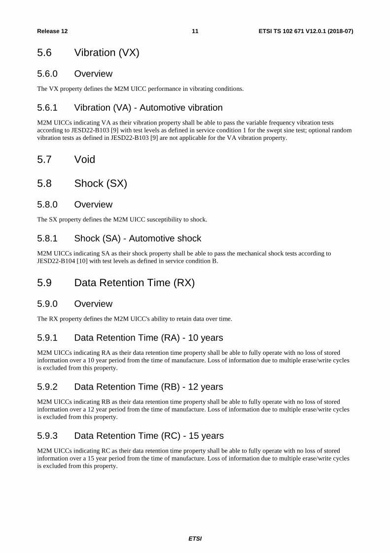
5.6 Vibration (VX)
5.6.0 Overview
The VX property defines the M2M UICC performance in vibrating conditions.
5.6.1 Vibration (VA) - Automotive vibration
M2M UICCs indicating VA as their vibration property shall be able to pass the variable frequency vibration tests according to JESD22-B103 [9] with test levels as defined in service condition 1 for the swept sine test; optional random vibration tests as defined in JESD22-B103 [9] are not applicable for the VA vibration property.
5.7 Void
5.8 Shock (SX)
5.8.0 Overview
The SX property defines the M2M UICC susceptibility to shock.
5.8.1 Shock (SA) - Automotive shock
M2M UICCs indicating SA as their shock property shall be able to pass the mechanical shock tests according to JESD22-B104 [10] with test levels as defined in service condition B.
5.9 Data Retention Time (RX)
5.9.0 Overview
The RX property defines the M2M UICC's ability to retain data over time.
5.9.1 Data Retention Time (RA) - 10 years
M2M UICCs indicating RA as their data retention time property shall be able to fully operate with no loss of stored information over a 10 year period from the time of manufacture. Loss of information due to multiple erase/write cycles is excluded from this property.
5.9.2 Data Retention Time (RB) - 12 years
M2M UICCs indicating RB as their data retention time property shall be able to fully operate with no loss of stored information over a 12 year period from the time of manufacture. Loss of information due to multiple erase/write cycles is excluded from this property.
5.9.3 Data Retention Time (RC) - 15 years
M2M UICCs indicating RC as their data retention time property shall be able to fully operate with no loss of stored information over a 15 year period from the time of manufacture. Loss of information due to multiple erase/write cycles is excluded from this property.
ETSI
ETSI TS 102 671 V12.0.1 (2018-07)12Release 12
5.10 Minimum Updates (UX)
5.10.0 Overview
The UX property defines the M2M UICC's expected minimum number of UPDATE commands (as specified in ETSI TS 102 221 [1]) supported for specified files, which are indicated as "high" in the "update activity" field.
5.10.1 Minimum Updates (UA) - 100 000
M2M UICCs indicating UA as their minimum number of UPDATE commands property shall be able to update the specified file(s), 100 000 times without failure. Loss of information due to time factors is excluded from this property.
5.10.2 Minimum Updates (UB) - 500 000
M2M UICCs indicating UB as their minimum number of update commands property shall be able to update the specified file(s), 500 000 times without failure. Loss of information due to time factors is excluded from this property.
5.10.3 Minimum Updates (UC) - 1 000 000
M2M UICCs indicating UC as their minimum number of update commands property shall be able to update the specified file(s), 1 000 000 times without failure. Loss of information due to time factors is excluded from this property.
6 M2M UICC - Physical Characteristics
6.0 Basic requirements Unless otherwise specified in the present specification the M2M UICC shall conform to the physical characteristics of the UICC as defined in ETSI TS 102 221 [1].
6.1 General M2M UICC physical characteristics
6.1.0 Introduction
This clause defines the general physical characteristics for the M2M UICC, both for the existing form factors and for the MFF.
6.1.1 Contacts
The logical definition of the contacts C1 to C8 shall be as defined in ETSI TS 102 221 [1].
6.2 Specific MFF physical characteristics
6.2.0 Introduction
This clause defines the specific physical characteristics for the MFF.
Two form factors are defined and called hereafter MFF1 and MFF2:
• MFF1 is well adapted for socketing.
• MFF2 offers the possibility to have a large heatsink in the middle.
NOTE: The MFF1 central contacts also allow heatsink dissipation.

ETSI
ETSI TS 102 671 V12.0.1 (2018-07)13Release 12
6.2.1 MFF1
6.2.1.0 Dimensions
The MFF1 shall have the following dimensions outlined in figure 6.1 and a thickness of 0,50 mm to 0,65 mm.
Figure 6.1: MFF1 bottom view
The inner tips of the outer contacting pads may be rectangular or rounded.
Table 6.1: Package pin to UICC contact mapping
Package pin UICC contact Package pin UICC contact 1 C5 8 C1 2 C6 7 C2 3 C7 6 C3 4 C8 5 C4

ETSI
ETSI TS 102 671 V12.0.1 (2018-07)14Release 12
Table 6.2: Dimensions of the MFF1
Parameter Description Dimensions (mm) E The package body dimension in the horizontal direction. 6,00 ± 0,10 D The package body dimension in the vertical direction. 5,00 ± 0,10 L The length of the outer contacting pad as measured from the edge of
the package. 0,60 ± 0,15
s The vertical distance from the bottom of the inner contacting pad to the top of the next inner contacting pad.
min 0,20
w The horizontal distance from the centre of the package to the furthest side of the inner contacting pad.
min 1,75
z The horizontal distance from the nearest sides of the outer and the inner contacting pad.
min 0,20
t the width of the connecting track that may connect corresponding inner and outer contacting pads on the surface of the MFF1.
max 0,20
y The horizontal distance from the centre of the package to the nearest side of the inner contacting pad.
0,20 ± 0,10
v The vertical distance between the side of the package and the nearest side of the nearest inner contacting pad.
min 0,10
b The width of the outer metallised outer contacting pads (including lead finish) exposed at the bottom surface of the package.
0,40 ± 0,10
b2 The width of the inner metallised contacting pads (including lead finish) exposed at the bottom surface of the package. The inner contacting pads may be elongated in the vertical direction without staying centred with the horizontal axis of the corresponding outer contacting pad as long as the gap between contacts is greater than s and the gap from the inner contacting pad to the edge of the package is greater than v and a minimum width of 0,7 mm stays centred with the horizontal axis of the corresponding outer contacting pad.
min 0,70
e The centreline-to-centreline spacing of the inner and outer contacting pads.
1,27 for tolerances see
parameters bbb and ddd bbb The tolerance that controls the position of the contact pattern with
respect to the horizontal package centreline. The centre of the tolerance zone for each contact is defined by basic dimension e as related to the horizontal package centreline.
0,10
ddd The tolerance that controls the position of the contacts to each other. The centres of the profile zones are defined by basic dimension e.
0,05
m Horizontal and vertical size of orientation mark. 0,25 ± 0,05
As outlined in figure 6.1, each MFF1 contact (C1 to C8) shall comprise the following contact areas:
• one small outer contacting pad aligned with the edge of the package; plus
• one larger inner contacting pad.
The inner and outer pads belonging to the same contact shall be electrically connected in the MFF1. This connection may be on the surface as long as the connecting track's width t is compliant with what is indicated for this parameter in table 6.2.
6.2.1.1 Orientation mark for the bottom of the package
An orientation mark shall be visible on the inner C5 contacting pad.
6.2.1.2 Orientation mark for top of package
The top of the package shall have an orientation mark located in the same corner as contact C5.
ETSI
ETSI TS 102 671 V12.0.1 (2018-07)15Release 12
6.2.2 MFF2
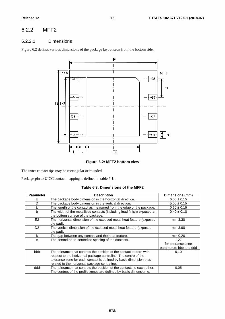
6.2.2.1 Dimensions
Figure 6.2 defines various dimensions of the package layout seen from the bottom side.
b
D
E
C1
C2
C3
C4
C5
C6
C7
C8
D2
e
L k E2
Pin 1Pin 8
Figure 6.2: MFF2 bottom view
The inner contact tips may be rectangular or rounded.
Package pin to UICC contact mapping is defined in table 6.1.
Table 6.3: Dimensions of the MFF2
Parameter Description Dimensions (mm) E The package body dimension in the horizontal direction. 6,00 ± 0,15 D The package body dimension in the vertical direction. 5,00 ± 0,15 L The length of the contact as measured from the edge of the package. 0,60 ± 0,15 b The width of the metallised contacts (including lead finish) exposed at
the bottom surface of the package. 0,40 ± 0,10
E2 The horizontal dimension of the exposed metal heat feature (exposed die pad).
min 3,30
D2 The vertical dimension of the exposed metal heat feature (exposed die pad).
min 3,90
k The gap between any contact and the heat feature. min 0,20 e The centreline-to-centreline spacing of the contacts. 1,27
for tolerances see parameters bbb and ddd
bbb The tolerance that controls the position of the contact pattern with respect to the horizontal package centreline. The centre of the tolerance zone for each contact is defined by basic dimension e as related to the horizontal package centreline.
0,10
ddd The tolerance that controls the position of the contacts to each other. The centres of the profile zones are defined by basic dimension e.
0,05

ETSI
ETSI TS 102 671 V12.0.1 (2018-07)16Release 12
6.2.2.2 Orientation mark for the bottom of the package
An orientation mark, located in the same corner as contact C5, shall be visible on the heat feature. This orientation mark may be a different shape than the one shown in figure 6.2.
6.2.2.3 Orientation mark for top of package
The top of the package shall have an orientation mark located in the same corner as contact C5.
7 Electrical and Logical specifications of the MFF UICC - Terminal interface
7.0 Requirements For a M2M UICC using MFF1 or MFF2, the following applies:
• Unless otherwise specified in the present specification the MFF shall conform to the electrical specifications of the UICC - Terminal interface as defined in ETSI TS 102 221 [1].
• The use of all contacts shall be as defined in ETSI TS 102 221 [1], ETSI TS 102 600 [4] and ETSI TS 102 613 [3] except as defined below.
• In the case where the MFF does not support the functionality as defined in ETSI TS 102 600 [4] then contacts C4 and C8 shall not be bonded.
• In the case where the MFF does not support the functionality as defined in ETSI TS 102 613 [3] then contact C6 shall not be bonded.
• Unless otherwise specified in the present specification the MFF shall conform to the logical characteristics of the UICC as defined in ETSI TS 102 221 [1].
7.1 Voltage Class support The M2M module supporting the present document shall not power the UICC using Voltage Class A.
8 Device Pairing Mechanism
8.0 Introduction The following mechanisms for device paring may be supported:
• Secure Channel pairing.
• CAT application pairing.
For each of the above pairing techniques, the M2M UICC shall decide the level of access that the terminal may have following the operation of the pairing mechanism.
8.1 Secure Channel Pairing The M2M UICC and terminal may securely pair and communicate by setting up a platform to platform APDU secure channel as described in ETSI TS 102 484 [5].

ETSI
ETSI TS 102 671 V12.0.1 (2018-07)17Release 12
Where the securing of information is not required, a reduced secure channel procedure may be followed:
• The support for secure channel and the requirement for a platform to platform secure channel shall be set in the ATR.
• There shall be an entry in the endpoints retrieved from the M2M UICC with the terminal application identifiers set to the ASCII encoded string "M2M pairing". If an entry for a platform to platform APDU secure channel exists then this shall take precedence.
• The platform to platform APDU secure channel setup process shall be completed and then terminated by the terminal immediately without any secure data being sent.
8.2 CAT application pairing The M2M UICC may use CAT (as specified in ETSI TS 102 223 [6]) to retrieve the terminal identity (e.g. IMEI, IMEISV, ESN, MEID, etc.) and to restrict access to UICC files and services as required.
ETSI
ETSI TS 102 671 V12.0.1 (2018-07)18Release 12
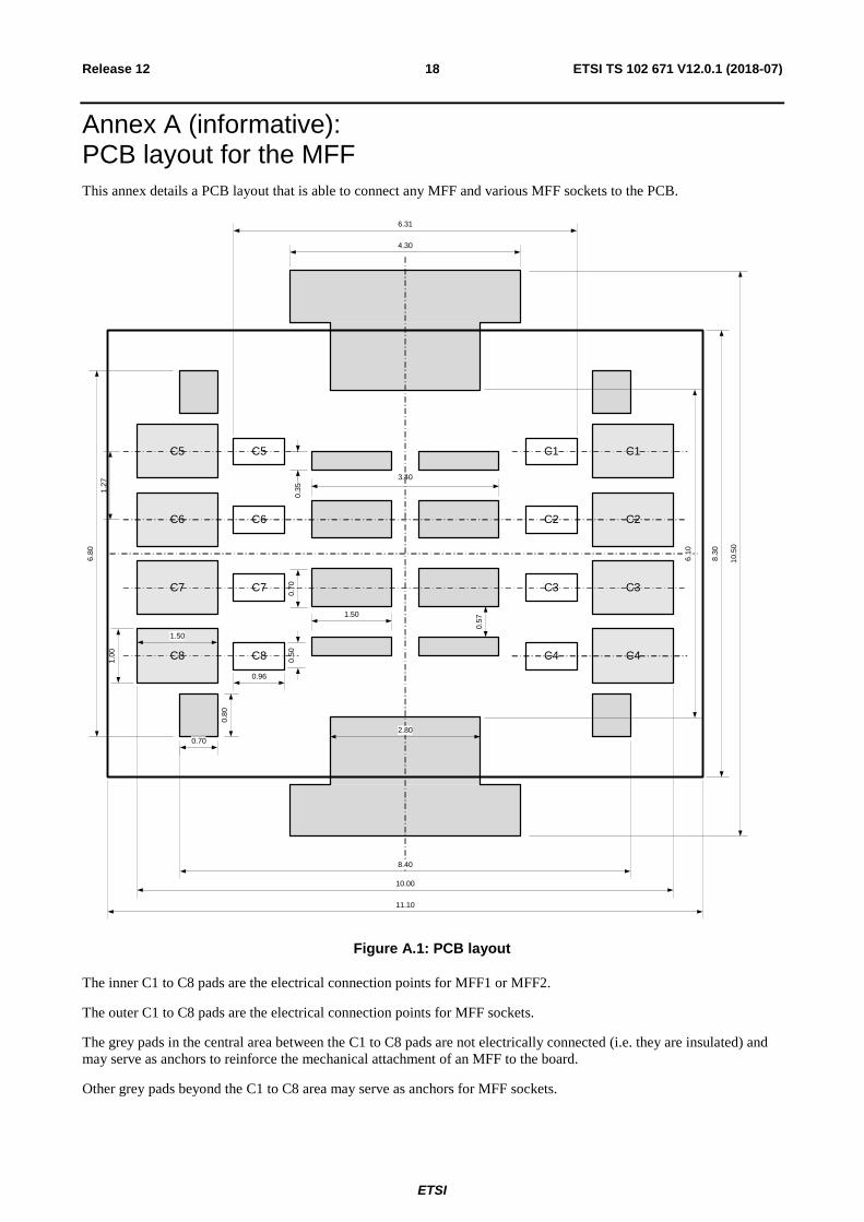
Annex A (informative): PCB layout for the MFF This annex details a PCB layout that is able to connect any MFF and various MFF sockets to the PCB.
C6
C5
C3
C2
C8
C7
1.50
0.70
3.40
C5 C1
C6 C2
C7 C3
C8 C4
6.31
0.96
1.27
0.50 C4
1.50
10.00
C1
2.80
4.30
0.70
0.80
8.40
6.10
10.5
0
6.80
1.00
0.35
0.57
11.10
8.30
Figure A.1: PCB layout
The inner C1 to C8 pads are the electrical connection points for MFF1 or MFF2.
The outer C1 to C8 pads are the electrical connection points for MFF sockets.
The grey pads in the central area between the C1 to C8 pads are not electrically connected (i.e. they are insulated) and may serve as anchors to reinforce the mechanical attachment of an MFF to the board.
Other grey pads beyond the C1 to C8 area may serve as anchors for MFF sockets.

ETSI
ETSI TS 102 671 V12.0.1 (2018-07)19Release 12
The rectangular box of 10,50 mm by 11,10 mm in figure A.1 is the recommended clearance zone to accommodate a wide range of MFF sockets. A minimum clearance area of 8,05 mm by 9,00 mm centered at the middle of the contact areas is a minimum to accommodate an MFF socket.
ETSI
ETSI TS 102 671 V12.0.1 (2018-07)20Release 12
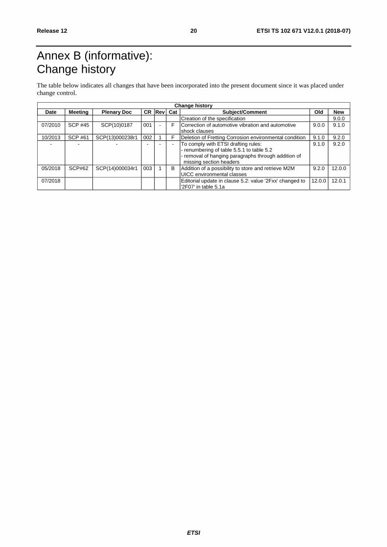
Annex B (informative): Change history The table below indicates all changes that have been incorporated into the present document since it was placed under change control.
Change history Date Meeting Plenary Doc CR Rev Cat Subject/Comment Old New
Creation of the specification 9.0.0 07/2010 SCP #45 SCP(10)0187 001 - F Correction of automotive vibration and automotive
shock clauses 9.0.0 9.1.0
10/2013 SCP #61 SCP(13)000238r1 002 1 F Deletion of Fretting Corrosion environmental condition 9.1.0 9.2.0 - - - - - - To comply with ETSI drafting rules:
- renumbering of table 5.5.1 to table 5.2 - removal of hanging paragraphs through addition of missing section headers
9.1.0 9.2.0
05/2018 SCP#62 SCP(14)000034r1 003 1 B Addition of a possibility to store and retrieve M2M UICC environmental classes
9.2.0 12.0.0
07/2018 Editorial update in clause 5.2: value '2Fxx' changed to '2F07' in table 5.1a
12.0.0 12.0.1

ETSI
ETSI TS 102 671 V12.0.1 (2018-07)21Release 12
History
Document history
V12.0.0 July 2018 Publication
V12.0.1 July 2018 Publication