trusystem™ 7500 or table - palmedico · in combination with the airo® mobile intraoperative ct...
TRANSCRIPT
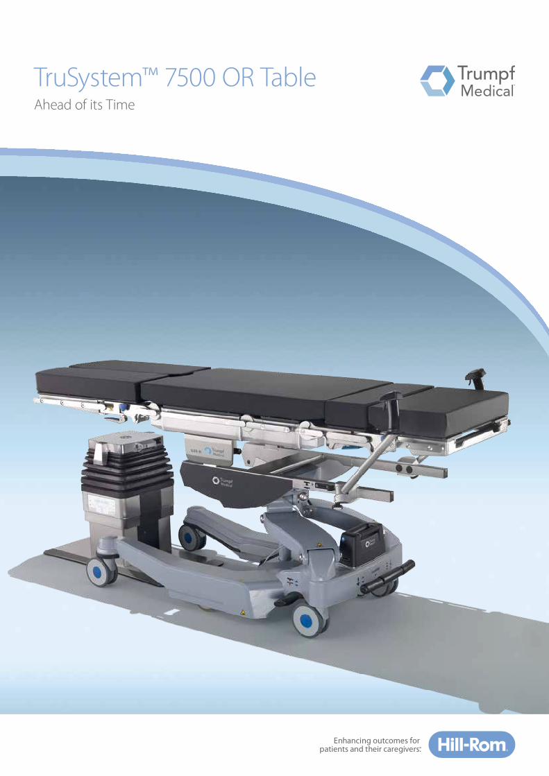
TruSystem™ 7500 OR Table Ahead of its Time
wo
b A
G
Cutting-Edge Technology – Now and in the Future
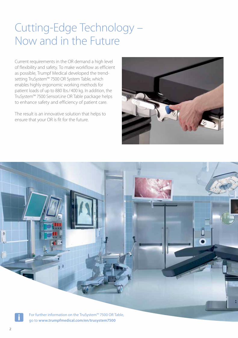
Current requirements in the OR demand a high level of flexibility and safety. To make workflow as efficient as possible, Trumpf Medical developed the trend- setting TruSystem™ 7500 OR System Table, which enables highly ergonomic working methods for patient loads of up to 880 lbs / 400 kg. In addition, the TruSystem™ 7500 SensorLine OR Table package helps to enhance safety and efficiency of patient care.
The result is an innovative solution that helps to ensure that your OR is fit for the future.
For further information on the TruSystem™ 7500 OR Table, go to www.trumpfmedical.com/en/trusystem7500
2
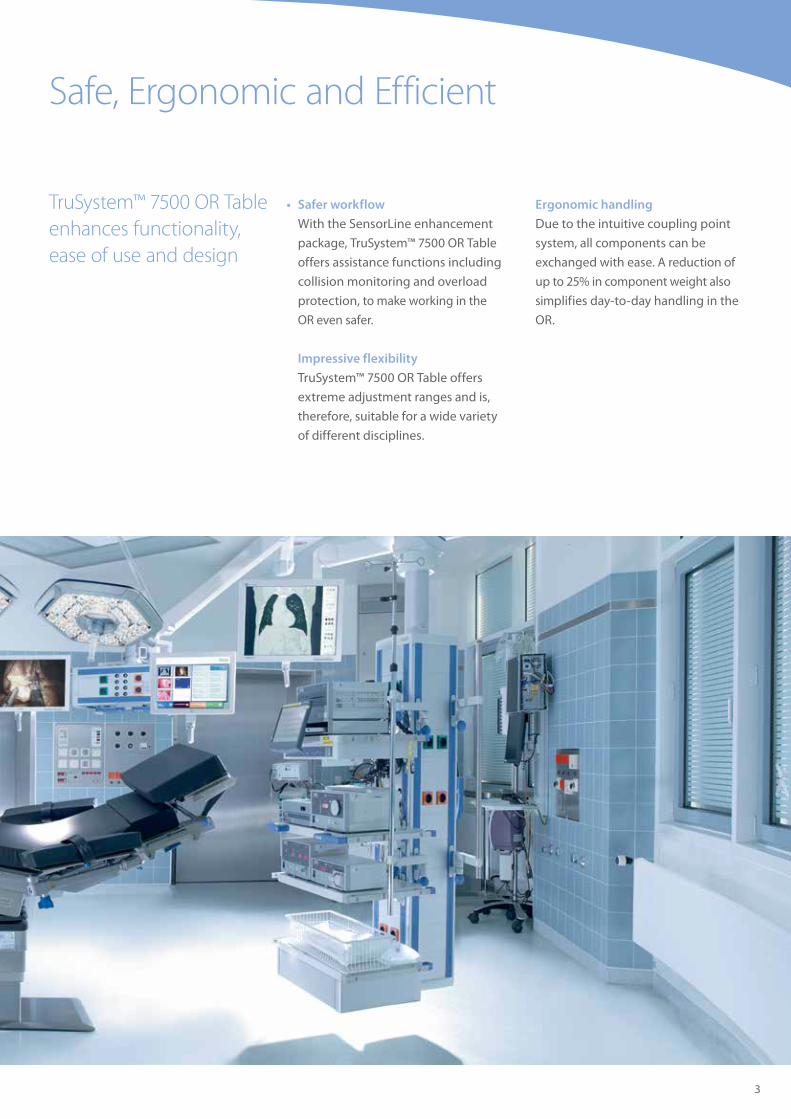
• Safer workflow
With the SensorLine enhancement
package, TruSystem™ 7500 OR Table
offers assistance functions including
collision monitoring and overload
protection, to make working in the
OR even safer.
Impressive flexibility
TruSystem™ 7500 OR Table offers
extreme adjustment ranges and is,
therefore, suitable for a wide variety
of different disciplines.
Ergonomic handling
Due to the intuitive coupling point
system, all components can be
exchanged with ease. A reduction of
up to 25% in component weight also
simplifies day-to-day handling in the
OR.
Safe, Ergonomic and Efficient
TruSystem™ 7500 OR Table enhances functionality, ease of use and design
3

TruSystem™ 7500 Hybrid OR Table – the Center for the Hybrid OR
The Hybrid OR with modern imaging is the future of integrated patient care. TruSystem™ 7500 Hybrid OR Table offers solution-based user-friendliness. The flexible inte gration interface allows for
TruSystem™ 7500 OR Table offers partners the ideal solution for interdisciplinary requirements during the operation.
communication with imaging processes, as well as the OR Integration System, TruConnect™, by Trumpf Medical. The table and other integrated systems are then controlled via a central module – for all-round intelligent networking.
4
Flexible integration interface for a multi-functional hybrid system
Get to know our partners at: www.trumpfmedical.com/en/partner
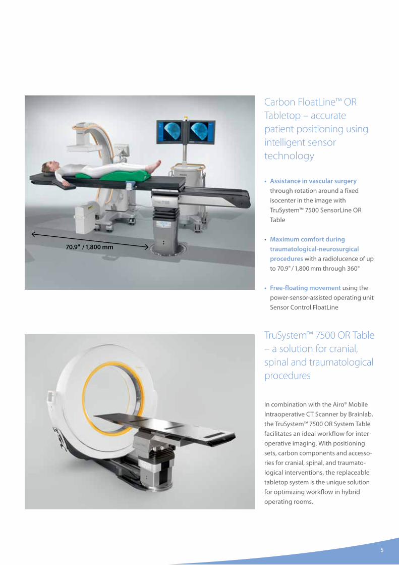
Carbon FloatLine™ OR Tabletop – accurate patient positioning using intelligent sensor technology
• Assistance in vascular surgery
through rotation around a fixed
isocenter in the image with
TruSystem™ 7500 SensorLine OR
Table
• Maximum comfort during
traumatological-neurosurgical
procedures with a radiolucence of up
to 70.9" / 1,800 mm through 360°
• Free-floating movement using the
power-sensor-assisted operating unit
Sensor Control FloatLine
TruSystem™ 7500 OR Table – a solution for cranial, spinal and traumatological procedures
In combination with the Airo® Mobile
Intraoperative CT Scanner by Brainlab,
the TruSystem™ 7500 OR System Table
facilitates an ideal workflow for inter-
operative imaging. With positioning
sets, carbon components and accesso-
ries for cranial, spinal, and traumato-
logical interventions, the replaceable
tabletop system is the unique solution
for optimizing workflow in hybrid
operating rooms.
5
70.9" / 1,800 mm
6
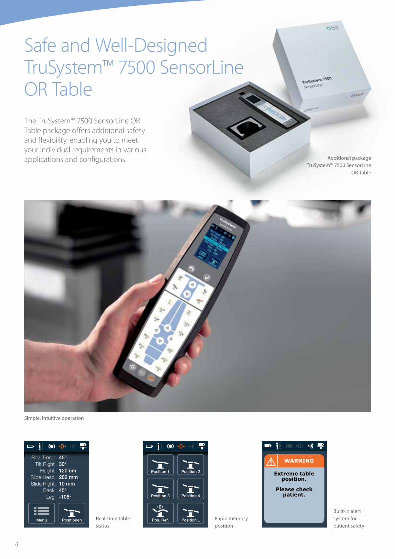
Safe and Well-Designed TruSystem™ 7500 SensorLine OR TableThe TruSystem™ 7500 SensorLine OR Table package offers additional safety and flexibility, enabling you to meet your individual requirements in various applications and configurations.
Simple, intuitive operation
Real-time table status
Rapid memory position
Built-in alert system for patient safety
Additional package TruSystem™ 7500 SensorLine
OR Table
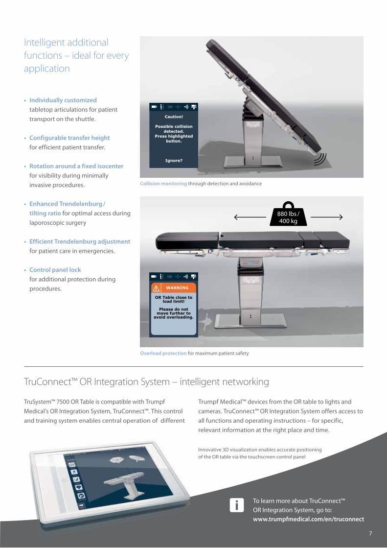
880 lbs / 400 kg
TruSystem™ 7500 OR Table is compatible with Trumpf
Medical’s OR Integration System, TruConnect™. This control
and training system enables central operation of different
Overload protection for maximum patient safety
Collision monitoring through detection and avoidance
• Individually customized
tabletop articulations for patient
transport on the shuttle.
• Configurable transfer height
for efficient patient transfer.
• Rotation around a fixed isocenter
for visibility during minimally
invasive procedures.
• Enhanced Trendelenburg /
tilting ratio for optimal access during
laporoscopic surgery
• Efficient Trendelenburg adjustment
for patient care in emergencies.
• Control panel lock
for additional protection during
procedures.
To learn more about TruConnect™ OR Integration System, go to: www.trumpfmedical.com/en/truconnect
7
Intelligent additional functions – ideal for every application
TruConnect™ OR Integration System – intelligent networking
Innovative 3D visualization enables accurate positioning of the OR table via the touchscreen control panel
Trumpf Medical™ devices from the OR table to lights and
cameras. TruConnect™ OR Integration System offers access to
all functions and operating instructions – for specific,
relevant information at the right place and time.
8
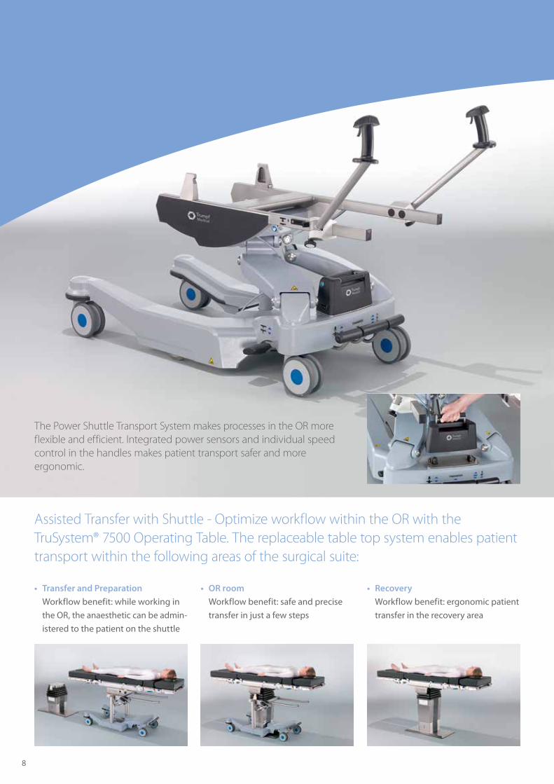
The Power Shuttle Transport System makes processes in the OR more flexible and efficient. Integrated power sensors and individual speed control in the handles makes patient transport safer and more ergonomic.
• Transfer and Preparation
Workflow benefit: while working in
the OR, the anaesthetic can be admin-
istered to the patient on the shuttle
• OR room
Workflow benefit: safe and precise
transfer in just a few steps
Assisted Transfer with Shuttle - Optimize workflow within the OR with the TruSystem® 7500 Operating Table. The replaceable table top system enables patient transport within the following areas of the surgical suite:
• Recovery
Workflow benefit: ergonomic patient
transfer in the recovery area
Assisted Patient Transfer with the Power Shuttle Transport System
9
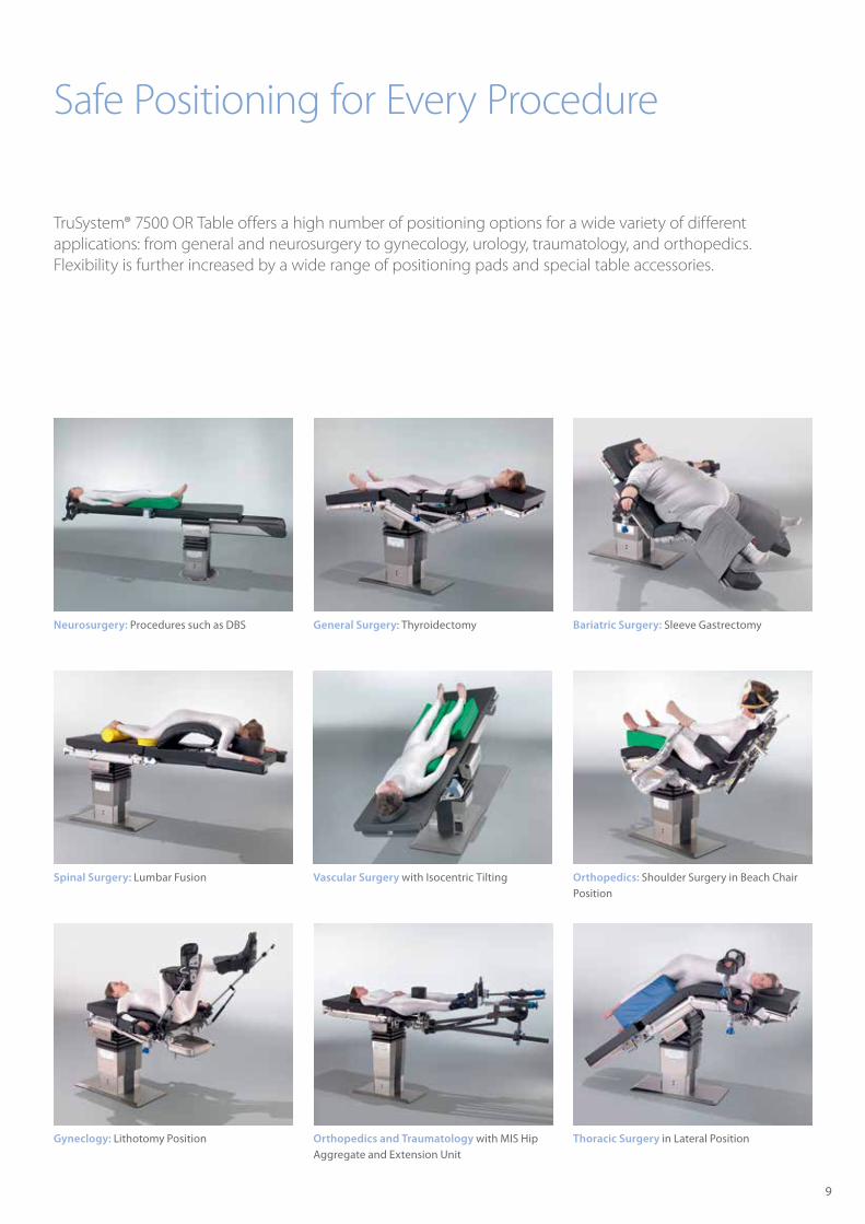
Safe Positioning for Every Procedure
TruSystem® 7500 OR Table offers a high number of positioning options for a wide variety of different applications: from general and neurosurgery to gynecology, urology, traumatology, and orthopedics. Flexibility is further increased by a wide range of positioning pads and special table accessories.
Orthopedics and Traumatology with MIS Hip Aggregate and Extension Unit
Thoracic Surgery in Lateral Position
Vascular Surgery with Isocentric Tilting
General Surgery: Thyroidectomy Bariatric Surgery: Sleeve Gastrectomy
Spinal Surgery: Lumbar Fusion
Neurosurgery: Procedures such as DBS
Orthopedics: Shoulder Surgery in Beach Chair Position
Gyneclogy: Lithotomy Position
2275 mm
1070 mm720 mm 485 mm
520 mm 300 mm
614 m
m
1164
mm
90°
105°
90°
105°
90°
55°
45°45°
460
400 mm
2037 mm
832 mm720 mm 485 mm
582 mm
90°
105°
90°
105°
U26H Geometrie U26H Darstellung Längsverschiebungsbereich U26H Darstellung Hub mit mobiler Säule
U26H Darstellung Verstellbereich Beinplattengelenk U26H Darstellung Verstellbereich oberes Rückenplattengelenk
U26H Verstellbereich unteres Rückenplattengelenk
U26H Verstellbereich Trendelenburg / AntitrendelenburgU14H Darstellung Längsverschiebungsbereich
U14H Geometrie
U14H Verstellbereich kopfseitiges Gelenk
UxxH Verstellbereich Kantung
30° 30°
mm
10
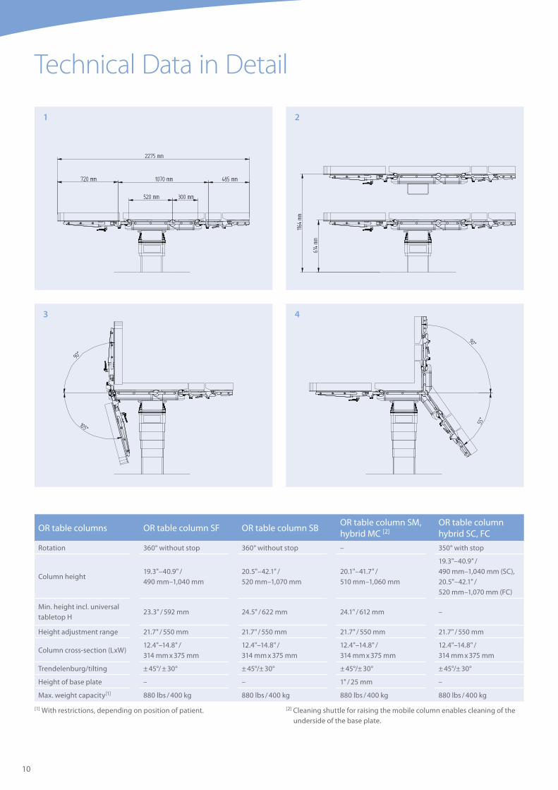
Technical Data in Detail
OR table columns OR table column SF OR table column SBOR table column SM, hybrid MC [2]
OR table column hybrid SC, FC
Rotation 360° without stop 360° without stop – 350° with stop
Column height19.3"–40.9" / 490 mm–1,040 mm
20.5"–42.1" / 520 mm–1,070 mm
20.1"–41.7" / 510 mm–1,060 mm
19.3"–40.9" / 490 mm–1,040 mm (SC), 20.5"–42.1" / 520 mm–1,070 mm (FC)
Min. height incl. universal tabletop H
23.3" / 592 mm 24.5" / 622 mm 24.1" / 612 mm –
Height adjustment range 21.7" / 550 mm 21.7" / 550 mm 21.7" / 550 mm 21.7" / 550 mm
Column cross-section (LxW)12.4"–14.8" / 314 mm x 375 mm
12.4"–14.8" / 314 mm x 375 mm
12.4"–14.8" / 314 mm x 375 mm
12.4"–14.8" / 314 mm x 375 mm
Trendelenburg/tilting ± 45°/ ± 30° ± 45°/± 30° ± 45°/± 30° ± 45°/± 30°
Height of base plate – – 1" / 25 mm –
Max. weight capacity[1] 880 lbs / 400 kg 880 lbs / 400 kg 880 lbs / 400 kg 880 lbs / 400 kg
[1] With restrictions, depending on position of patient. [2] Cleaning shuttle for raising the mobile column enables cleaning of the underside of the base plate.
3 4
1 2

2275 mm
1070 mm720 mm 485 mm
520 mm 300 mm
614 m
m
1164
mm
90°
105°
90°
105°
90°
55°
45°45°
460
400 mm
2037 mm
832 mm720 mm 485 mm
582 mm
90°
105°
90°
105°
U26H Geometrie U26H Darstellung Längsverschiebungsbereich U26H Darstellung Hub mit mobiler Säule
U26H Darstellung Verstellbereich Beinplattengelenk U26H Darstellung Verstellbereich oberes Rückenplattengelenk
U26H Verstellbereich unteres Rückenplattengelenk
U26H Verstellbereich Trendelenburg / AntitrendelenburgU14H Darstellung Längsverschiebungsbereich
U14H Geometrie
U14H Verstellbereich kopfseitiges Gelenk
UxxH Verstellbereich Kantung
30° 30°
mm
11
Drawings 1–7: OR table column mobile with universal OR tabletop U26 H Drawing 8: OR table column mobile with universal OR tabletop U14 H
OR tabletops Universal OR tabletops [3] [4] [5] [6] Special OR tabletops [3] [4] [5]
U14 H U24 H U26 H ST26 H Carbon FloatLine™Length 32.8" / 832 mm 42.1" / 1,070 mm 42.1" / 1,070 mm 39.5" / 1,070 mm 87.8" / 2,229 mm
Width across standard rails
23.6" / 600 mm 23.6" / 600 mm 23.6" / 600 mm 23.6" / 600 mm 20.5" / 520 mm
Adjustment range joint leg plate
+ 90°/– 105° + 90°/– 105° + 90°/– 105° + 90°/– 105° –
Adjustment range joint upper back section input
– + 90°/– 70° + 90°/– 105° + 90°/– 105° –
Adjustment range joint lower back section input
+ 90°/– 105° + 90°/– 55° + 90°/– 55° + 90°/– 55° –
Trendelenburg – – – ± 20° –
Longitudinal shift 18.1" / 460 mm 15.7" / 400 mm 15.7" / 400 mm 13.8" / 400 mm 31.5" / 800 mm
Transverse shift – – – – ± 4.9" / 125 mm
7
6
8
5
[3] Different operating devices available: cable remote control and chargers for wireless remote control (mobile and wall installation).
[4] H tabletops are available with Balanced pads, CFL and ST26 are available with Balanced or Comfort Plus pads.
[5] The universal OR tabletops are also available as a washable version.
wo
b A
G
Trumpf Medical, part of Hill-Rom, is distinguished by high-quality German
engineering standards and offers innovative products to improve efficiency
and safety in the OR, ICU, and in other clinical environments throughout
the care sector. With our customers’ requirements as our benchmark and
innovation as the foundation of our success, Trumpf Medical delivers total
solutions to fit your clinical care needs.
This document is destined solely for use by healthcare professionals. Medical devices shown in this brochure are intended for use with patients in departments of healthcare establishments.
These products are regulated health care products which, where required by applicable regulations, bear a CE mark. Hill-Rom recommends you carefully read the detailed instructions for safe and proper use included in the documentation accompanying the medical devices. The personnel of healthcare establishments are responsible for the proper use and maintenance of these medical devices.
TruConnect™ and TruSystem™ are registered trademarks of TRUMPF GmbH+ Co. KG. Airo® is a registered trademark of Brainlab AG.
Hill-Rom reserves the right to make changes without notice in design, specifications and models. The only warranty Hill-Rom makes is the express written warranty extended on the sale or rental of its products.
©2017 Hill-Rom Services, Inc. ALL RIGHTS RESERVED. Doc. No: 2068151, 15 February 2017
Not all products/options are available in all countries. For further information about our products or services, please contact your local Trumpf Medical representative or visit our webpage:
www.trumpfmedical.com
Hill-Rom is a leading global medical technology company with more than
10,000 employees in over 100 countries. We partner with health care
providers by focusing on patient care solutions that improve clinical and
economic outcomes in five core areas: Advancing Mobility, Wound Care
and Prevention, Clinical Workflow, Surgical Safety and Efficiency, and
Respiratory Health. Hill-Rom people, programs, and product brands
work towards one mission: Every day, around the world, we enhance
outcomes for our patients and their caregivers.