trusses - statics.marcks.ccstatics.marcks.cc/mod13/pdf/mod13.pdf · if this shear force is...
TRANSCRIPT

TRUSSES
Church TrussChurch TrussVermont Timber WorksVermont Timber Works

Consider a loaded beam of rectangular cross section as shown on the next page. When such a beam is loaded, it is subjected to three internal actions: an axial force (A), a shear force (V), and an internal bending moment (M)
The internal bending moment is a direct result of the induced shear force. If this shear force is eliminated, the bending moment is also eliminated. The end result is a tensile or compressive axial force
Since this loaded beam does deflect (bend), the top of the beam will be subjected to compressive forces while the bottom of the beam will be subjected to tensile forces
The magnitudes of these forces and moments and their internal distribution depends upon several factors. The details of this are beyond the scope of a course in statics but will be developed in a Strength of Materials course. For now, simply accept these phenomena at face value
2
Truss Action

(a) A simply supported beam of rectangular cross section is shown with a point load at midspan. Consider a section of the beam between the two dotted lines
(b) Force 'F' induces an internal shear (V) and axial (A) force. The shear force causes an internal bending moment (M)
3
Truss ActionF
F
V A MM A V

But if one replaces the beam with a truss as shown below, all shear forces within the beam are translated to pure compressive and tensile forces in the truss members. Since there is no shear, there is no bending moment. The members of a truss are concurrent at a point. This point, or joint, can be modeled as a pin, thus resists no moment
This is referred to as truss action. That is, all members are axially loaded, adjoining members are concurrent at a joint, and the joints do not resist a moment
4
Truss Action
Compression
Tension
F
TT
C Each of these elements of truss action are critical elements to understand. Let's now look at truss construction necessary to achieve this action
Depiction of Normal Truss Action. The dark dottedline is the original beam.

All trusses share the following characteristics: Must be inherently stable Must consist of two-force members connected by pins Must be loaded only at the joints or pins
A truss is inherently stable A truss must be stable under design load. Since the triangle is the only
polygon that is inherently stable, all trusses are constructed by connecting a series of triangles. Structures built of squares, pentagons, etc. are unstable unless externally reinforced
5
Truss Construction
Multi-sided Structure will deflect underload unless externally reinforced
A triangular structure is rigid and stable under load

A truss consists of two-force members connected by pins As demonstrated in the section defining truss action, the members of a
truss are and only need be two-force members. As such a member cannot be continuous through a pin. If they were, that member would be a multi-force member and the structure is no longer a truss. It could not be analyzed using standard truss analysis methods. It would need to be analyzed as a frame
Since truss members are two-force members, they are connected by pins that do not resist moment. As such, each pin joint is a point of concurrency of the forces within the members attached to that pin
Truss loads can only occur at their joints Since truss members are two-force members, they can be subjected to
compressive and tensile loads only and cannot be loaded at centerspan. Furthermore, these members are sized for axial tensile and compressive loads, not for bending loads. If a member is loaded at mid-span, it is no longer a two-force member. It will not exhibit normal truss action. It will be subjected to bending stresses and may be prone to failure
6
Truss Construction

Actual Construction vs Analysis The description of a truss, as presented on previous pages, appears to
contradict how trusses are constructed and applied in the field. Although there is some truth to this, it is acceptable and necessary so as to develop a model of the truss for analysis
77
Consider the truss shown in the photo. It is apparent the top chords of the truss are single members passing through a joint. It is also apparent the bottom center joint is not a pin. Furthermore, although supports are not shown, it is unlikely the truss is simply supported
A proper model of this truss is shown with an assumed load
Architectural Truss by Vermont Timber Works
Truss Construction

Actual Construction vs Analysis It is known that a small moment exists at the pin connections illustrated on
the previpous page simply because the connection is not a true pin. However, both the gusset plate construction at the joint and the 'continuous member' can be modeled as shown because the moments induced are not significant
In reality, the members are welded, tied together with a gusset plate, or even constructed with mortise and tenon joints for log home construction. Each joint is treated as a pinned joint for purposes of analysis
88
Bolted Gusset Plateon a Wood Truss
A Pinned Connection Mortise and Tenon Joint on Trusses For Log Homes
Truss Construction


Actual Construction vs Analysis Another point that deserves further discussion is the loading of a truss
along a member. If one were to look at the trusses of most homes today, one would see the roof sheathing nailed directly to the truss. Then, as the roof of the structure is loaded (i.e.: snow, wind, etc.), this load is transferred directly to the length of the member. In other words, the member is loaded with a uniform distribution along its length. As such, the member is placed in bending and is no longer a two-force member
Trusses, as applied to most homes today, do not exhibit true truss action. However, the simple structure of a single family dwelling is such that the loads are not generally very large. The truss, even though improperly loaded, easily handles the induced bending loads without failure
10
Truss Construction
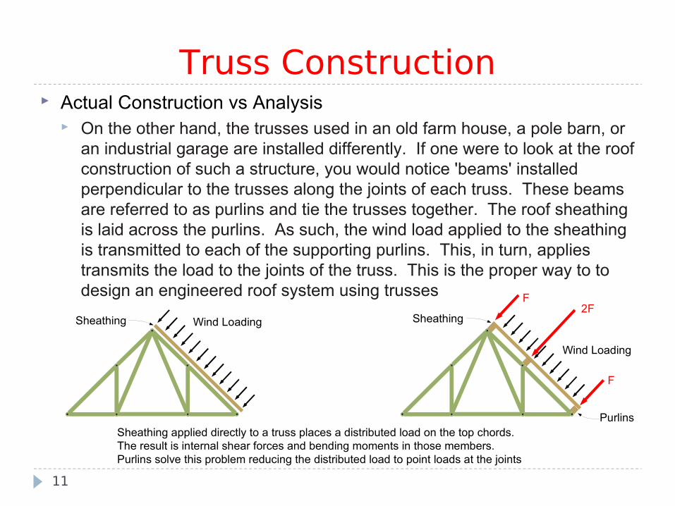
Actual Construction vs Analysis On the other hand, the trusses used in an old farm house, a pole barn, or
an industrial garage are installed differently. If one were to look at the roof construction of such a structure, you would notice 'beams' installed perpendicular to the trusses along the joints of each truss. These beams are referred to as purlins and tie the trusses together. The roof sheathing is laid across the purlins. As such, the wind load applied to the sheathing is transmitted to each of the supporting purlins. This, in turn, applies transmits the load to the joints of the truss. This is the proper way to to design an engineered roof system using trusses
11
Sheathing applied directly to a truss places a distributed load on the top chords. The result is internal shear forces and bending moments in those members. Purlins solve this problem reducing the distributed load to point loads at the joints
Wind Loading
Wind Loading
SheathingSheathing
Purlins
F
F2F
Truss Construction

Simple Truss As stated earlier, the simpliest rigid structure is a triangle. As such, a
simple truss begins as a triangle and can be constructed by adding two members and a joint
The Warren truss shown below is one of the simpliest trusses. It begins with three members and three joints as shown on the left. Construction continues by adding two members and a joint (as illustrated below by the different colors). This is a simple truss
12
Truss Designations
A Warren truss constructed with a series of simple triangles

A Compound Truss A compound truss is constructed by combining two or more simple
trusses together. It is often used where large spans are necessary Consider the Fink Truss below. The left side of the truss is actually a
simple truss ABC. The right side is also a simple truss BDE. In this case, BDE is a mirror image of ABC but does not have to be. These two trusses share a common pin at 'B' and are tied with a single two-force member CD. This constitutes a compound truss
13
Truss Designations
13
The Fink truss shown above is a typical roof truss. It is comprised of two simple trusses sharing a pin at 'B' and made stable with a tie at CD
A
B
CE
D

A Complex Truss A complex truss is one that cannot be considered a simple truss or a
compound truss Consider the truss shown below. It consists of six members and five pins.
Upon inspection, one can see this truss does not begin as a simple truss. In other words, there is no stable substructure comprised of three members and three pins. Since a compound truss is a combination of simple trusses, this is not a compound truss. Rather, this qualifies as a complex truss
14
Truss Designations
A scissor trussA
B
C
D
E
Types of Trusses Prior to the development of steel, trusses were built of wood. One of the
many applications of trusses were wooden bridges. Engineers of the day would develop certain types of trusses for a particular structure they were designing. Popular truss configurations were often referred to by the name of the engineer, but often took on a more descriptive name
Some of the more common trusses are listed on the following pages. By no means is this an exhaustive list
Can you pick out which trusses are typically used for roof structures and which are typically used for bridge structures?
15
Truss Designations

16
Truss Designations
Pratt Truss
Howe Truss
Long Truss
K-Truss
Warren Truss
Modified Warren Truss
Fink Truss
Belgian Truss
Scissor Truss
Alternate Bowstring Truss
Bowstring Truss
Bowstring K-Truss