truck mounted, 2 point & 3 point supersprayer ... -...
TRANSCRIPT

SUMMERS®
Operator’sManual
SUPERSPRAYER
SUMMERS MANUFACTURING CO., INC.WEB SITE: www.summersmfg.com
MADDOCK, NORTH DAKOTA 58348 .................................. (701) 438-2855DEVILS LAKE, NORTH DAKOTA 58301 .............................. (701) 662-5391
8Z1103 © Summers Mfg. Co., Inc. 2007 Printed in USA
IMPORTANTTHE OPERATOR IS RESPONSIBLE FORADJUSTING THE MACHINE SINCE MA-CHINE DOES NOT COME “FIELDREADY” FROM FACTORY.
CAUTIONREAD & UNDERSTAND OPERATOR’SMANUAL BEFORE USING MACHINE.
TRUCK MOUNTED2 POINT & 3 POINT

WarrantySummers warrants only products of its manufacture against operational failure caused by defec-tive materials or workmanship which occur during normal use within 12 months from the date ofpurchase by the end user from Summers’ dealer. Summers’ obligation is to replace free ofcharge any part of any product that Summers inspection shows to be defective excluding trans-portation charges to Maddock, ND or Devils Lake, ND and return and also excluding all transpor-tation costs from Summers’ dealer to the dealer’s customer and all other costs such as removaland installation expense. Summers shall not be liable for loss of time, manufacturing costs,labor, material, loss of profits, consequential damages, direct or indirect, because of defectiveproducts whether due to rights arising under the contract of sale or independently thereof, andwhether or not such claim is based on contract, tort or warranty. Written permission for anywarranty claim return must be first obtained from authorized Summers’ personnel. All returnsmust be accompanied with a complete written explanation of claimed defects and the circum-stances of operational failure. Written warranty for all component parts used in the manufactureof Summers products is available upon request. Warranty of such component parts will be deter-mined by said component manufacturer upon their inspection of the claimed defective part. Thisexpress warranty is the sole warranty of Summers. There are no warranties, which extend be-yond the warranty herein expressly set forth. The sales for products of Summers under any otherwarranty or guarantee express or implied is not authorized. This warranty voids all previousissues
SUMMERS MANUFACTURING CO. INC.MADDOCK, NORTH DAKOTA 58348 DEVILS LAKE, NORTH DAKOTA 58301
2/95
INTRODUCTION
This manual provides the following information about your Summers Field Sprayer.
SECTION CONTENTSSection 1 – SAFETY explains important safety precautions and familiarizes the Operator with the
decals and their locations.
Section 2 – GENERAL INFORMATION describes standard and optional features of the sprayer.
Section 3 – SPRAYER OPERATION provides all necessary information for the operation and adjust-ment of the sprayer.
Section 4 – MAINTENANCE covers both spraying system and mechanical maintenance plus propercleaning and storage.
Section 5 – TROUBLESHOOTING provides a quick reference to solving problems.
Section 6 – SPECIFICATIONS lists important dimensions, capacities and other technical informa-tion.
Section 7 – PARTS
OTHER ITEMS OF IMPORTANCE
A. Summers Mfg. Co., Inc. strongly recommends that each Field Sprayer Operator READ and UNDER-STAND the Operator’s Manual before using the machine. In addition, this Operator’s Manual shouldbe REVIEWED at least ANNUALLY thereafter.
B. It is the policy of this company to improve its products whenever possible and practical to do so. Wereserve the right to make changes or improvements in the design or construction of parts at any timewithout incurring obligations to install such changes on products previously delivered.
C. Reference to “right” and “left” in this manual is determined from a seated position in the driversseat.
D. Parts are referenced in each drawing with the Summers Manurfacturing Part Number. Use this PartNumer when ordering replacement parts from your Summers dealer. See back section of manual fordescription of each Part Number.
OWNER REGISTER
Name ___________________________________ Size _________________________________________
Address _________________________________ Serial Number _______________________________
City _____________________________________
State/Prov. ______________________________ Date Purchased _____________________________
Mail Code _______________________________ Dealer ______________________________________
(located on frame)
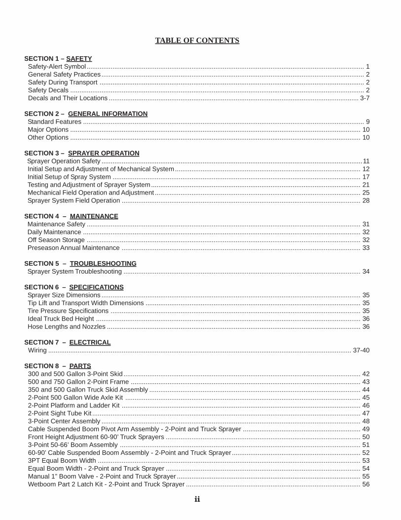
TABLE OF CONTENTS
SECTION 1 – SAFETY Safety-Alert Symbol ....................................................................................................................................................... 1 General Safety Practices ............................................................................................................................................... 2 Safety During Transport ................................................................................................................................................ 2 Safety Decals ................................................................................................................................................................ 2 Decals and Their Locations ........................................................................................................................................ 3-7
SECTION 2 – GENERAL INFORMATION Standard Features ......................................................................................................................................................... 9 Major Options .............................................................................................................................................................. 10 Other Options .............................................................................................................................................................. 10
SECTION 3 – SPRAYER OPERATION Sprayer Operation Safety ..............................................................................................................................................11 Initial Setup and Adjustment of Mechanical System..................................................................................................... 12 Initial Setup of Spray System ....................................................................................................................................... 17 Testing and Adjustment of Sprayer System.................................................................................................................. 21 Mechanical Field Operation and Adjustment ................................................................................................................ 25 Sprayer System Field Operation .................................................................................................................................. 28
SECTION 4 – MAINTENANCE Maintenance Safety ..................................................................................................................................................... 31 Daily Maintenance ....................................................................................................................................................... 32 Off Season Storage ..................................................................................................................................................... 32 Preseason Annual Maintenance .................................................................................................................................. 33
SECTION 5 – TROUBLESHOOTING Sprayer System Troubleshooting ................................................................................................................................. 34
SECTION 6 – SPECIFICATIONS Sprayer Size Dimensions ............................................................................................................................................. 35 Tip Lift and Transport Width Dimensions ..................................................................................................................... 35 Tire Pressure Specifications ........................................................................................................................................ 35 Ideal Truck Bed Height ................................................................................................................................................ 36 Hose Lengths and Nozzles .......................................................................................................................................... 36
SECTION 7 – ELECTRICAL Wiring ..................................................................................................................................................................... 37-40
SECTION 8 – PARTS 300 and 500 Gallon 3-Point Skid ................................................................................................................................. 42 500 and 750 Gallon 2-Point Frame ............................................................................................................................. 43 350 and 500 Gallon Truck Skid Assembly ................................................................................................................... 44 2-Point 500 Gallon Wide Axle Kit ................................................................................................................................ 45 2-Point Platform and Ladder Kit .................................................................................................................................. 46 2-Point Sight Tube Kit .................................................................................................................................................. 47 3-Point Center Assembly ............................................................................................................................................. 48 Cable Suspended Boom Pivot Arm Assembly - 2-Point and Truck Sprayer ................................................................ 49 Front Height Adjustment 60-90’ Truck Sprayers .......................................................................................................... 50 3-Point 50-66’ Boom Assembly ................................................................................................................................... 51 60-90’ Cable Suspended Boom Assembly - 2-Point and Truck Sprayer ...................................................................... 52 3PT Equal Boom Width ............................................................................................................................................... 53 Equal Boom Width - 2-Point and Truck Sprayer .......................................................................................................... 54 Manual 1” Boom Valve - 2-Point and Truck Sprayer .................................................................................................... 55 Wetboom Part 2 Latch Kit - 2-Point and Truck Sprayer ............................................................................................... 56
ii
iii
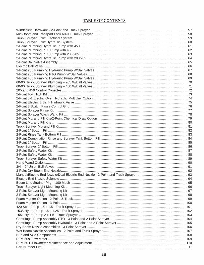
Windshield Hardware - 2-Point and Truck Sprayer ....................................................................................................... 57Mid-Boom and Transport Lock 60-90’ Truck Sprayer .................................................................................................... 58Truck Sprayer Tiplift Electrical System .......................................................................................................................... 59Truck Sprayer Tiplift Hydraulic System .......................................................................................................................... 602-Point Plumbing Hydraulic Pump with 450 .................................................................................................................. 612-Point Plumbing PTO Pump with 450 .......................................................................................................................... 622-Point Plumbing PTO Pump with 203/205 ................................................................................................................... 632-Point Plumbing Hydraulic Pump with 203/205 ........................................................................................................... 642-Point Ball Valve Assembly .......................................................................................................................................... 65Electric Ball Valve .......................................................................................................................................................... 663-Point 205 Plumbing Hydraulic Pump W/Ball Valves ................................................................................................... 673-Point 205 Plumbing PTO Pump W/Ball Valves ........................................................................................................... 683-Point 450 Plumbing Hydraulic Pump W/Ball Valves ................................................................................................... 6960-90’ Truck Sprayer Plumbing – 205 W/Ball Valves..................................................................................................... 7060-90’ Truck Sprayer Plumbing – 450 W/Ball Valves..................................................................................................... 71205 and 450 Control Consoles ...................................................................................................................................... 722-Point Tow Hitch Kit ..................................................................................................................................................... 732-Point 3-1 Electric Over Hydraulic Multiplier Option .................................................................................................... 742-Point Electric 3 Bank Hydraulic Valve ........................................................................................................................ 752-Point 3 Switch Fasse Control Grip ............................................................................................................................. 762-Point Sprayer Rinse Kit .............................................................................................................................................. 772-Point Sprayer Wash Wand Kit .................................................................................................................................... 782-Point Mix and Fill Kits/2-Point Chemical Draw Option ................................................................................................ 793-Point Mix and Fill Kits ................................................................................................................................................. 80Truck Sprayer Mix and Fill Kit ........................................................................................................................................ 812-Point 2” Bottom Fill ..................................................................................................................................................... 822-Point Rinse Tank Bottom Fill ...................................................................................................................................... 832-Point Combination Rinse and Sprayer Tank Bottom Fill ............................................................................................. 843-Point 2” Bottom Fill ..................................................................................................................................................... 85Truck Sprayer 2” Bottom Fill .......................................................................................................................................... 862-Point Safety Water Kit ................................................................................................................................................ 873-Point Safety Water Kit ................................................................................................................................................ 88Truck Sprayer Safety Water Kit ..................................................................................................................................... 89Hand Wand Option ........................................................................................................................................................ 903/4 – 2” Union Ball Valves ............................................................................................................................................. 913-Point Dry Boom End Nozzle ....................................................................................................................................... 92Manual/Electric End Nozzle/Dual Electric End Nozzle - 2-Point and Truck Sprayer ..................................................... 93Electric End Nozzle Solenoid ........................................................................................................................................ 94Boom Line Strainer Pkg. - 100 Mesh ............................................................................................................................. 95Truck Sprayer Light Mounting Kit .................................................................................................................................. 963-Point Sprayer Light Mounting Kit ................................................................................................................................ 972-Point Sprayer Light Mounting Kit ................................................................................................................................ 98Foam Marker Option - 2-Point & Truck .......................................................................................................................... 99Foam Marker Option - 3-Point ..................................................................................................................................... 100420 Scot Pump 1.5 x 1.5 - Truck Sprayer .................................................................................................................... 1011538 Hypro Pump 1.5 x 1.25 - Truck Sprayer ............................................................................................................. 1021551 Hypro Pump 2 x 1.5 - Truck Sprayer .................................................................................................................. 103Centrifugal Pump Assembly PTO - 3-Point and 2-Point Sprayer ................................................................................. 104Centrifugal Pump Assembly Hydraulic - 3-Point and 2-Point Sprayer ......................................................................... 105Dry Boom Nozzle Assemblies - 3-Point Sprayer ......................................................................................................... 106Wet Boom Nozzle Assemblies - 2-Point and Truck Sprayer ........................................................................................ 107Hub and Axle Components .......................................................................................................................................... 108RFM 60s Flow Meter ................................................................................................................................................... 109RFM 60 P Flowmeter Maintenance and Adjustment ................................................................................................... 110Part Number List .......................................................................................................................................................... 111
TABLE OF CONTENTS

NOTES

SECTION 1 - SAFETY
1.1 SAFETY-ALERT SYMBOL
This symbol is used to indicate a potential personalinjury hazard. This symbol means:
ATTENTION! BECOME ALERT!YOUR SAFETY IS INVOLVED!
Definition of each Signal Word used in conjunction with the Safety-Alert symbol.
indicates an imminently hazardous situation which, if not avoided, will result in death orserious injury. This signal word is to limited to the most extreme situations.
indicates a potentially hazardous situation which, if not avoided,could result in deathor serious injury.
indicates a potentially hazardous situation which, if not avoided, may result in minor ormoderate injury. It may also be used to alert against unsafe practices.
DANGER
WARNING
CAUTION
1
USING CHEMICALS?HIGH HAZARD REQUIRES:*goggles*respirator*avoid fumes*rubber gloves and skin protection
MODERATE HAZARD REQUIRES:*goggles*avoid fumes*rubber gloves and skin protection
LOW HAZARD REQUIRES:*avoid fumes*rubber gloves and skin protection
PROTECT YOURSELF!
1. REFER TO SIGNAL WORD AND REQUIRED PER-SONAL PROTECTIVE EQUIPMENT WHEN USINGCHEMICALS.
2. ALWAYS READ AND FOLLOW CHEMICAL MANU-FACTURERS’ WARNINGS, INSTRUCTIONS ANDPROCEDURES BEFORE USING.
3. HANDLE CHEMICALS WITH EXTREME CARE.
4. IN CASE OF POISONING, GET IMMEDIATE MEDI-CAL ATTENTION. A CONTAINER LABEL MAY BEBENEFICIAL FOR QUICK TREATMENT.
5. BE SAFE!
SECTION 1 - SAFETY
2
1.2 GENERAL SAFETY PRACTICES1. READ AND UNDERSTAND Operator’s Manual before using machine. Review at least
annually thereafter.
2. VERIFY all safety devices and shields are in place before using machine.
3. KEEP hands, feet, hair and clothing away from moving parts.
4. STOP engine, place all controls in neutral, set parking brake, remove ignition key and waitfor all moving parts to stop before servicing, adjusting, maintaining or unplugging.
5. BE CAREFUL when working around high-pressure hydraulic system.
6. DO NOT ALLOW RIDERS.
7. USE EXTREME CARE when cleaning, filling or making adjustments.
8. ALWAYS READ chemical container label carefully and follow chemical manufacturers’ WARN-INGS, instructions and procedures before using.
9. AVOID having excess chemical stored after spraying.
10. ONLY STORE chemicals in their original containers in a locked area.
11. KEEP CHILDREN AWAY from chemicals and sprayer equipment.
12. ALWAYS make sure that pressure is relieved from hydraulic circuits before servicing ordisconnecting from tractor.
13. NEVER allow anyone to walk or work under a raised piece of equipment.
1.3 SAFETY DURING TRANSPORT1. ONLY TRANSPORT at a safe speed. Use caution when making corners or meeting traffic.
Abrupt maneuvering may cause a loss of control.
2. USE a safety pin and clip on boom rest to secure boom when transporting. Booms must befolded and secured during transport. SPRING LOADED LATCH IS NOT DESIGNED TOSECURE BOOMS DURING TRANSPORT.
3. MOUNT a red flag to outer width of sprayer when transporting long distances to warn motor-ists of an over wide machine. Operator is responsible for following all local laws governingtransport of farm machinery.
1.4 SAFETY DECALS1. KEEP SAFETY DECALS CLEAN.
2. REPLACE missing or unreadable decals. New decals are available from your Summersdealer (by stating correct part number (PN) located on the decal).
3
SECTION 1 - SAFETY
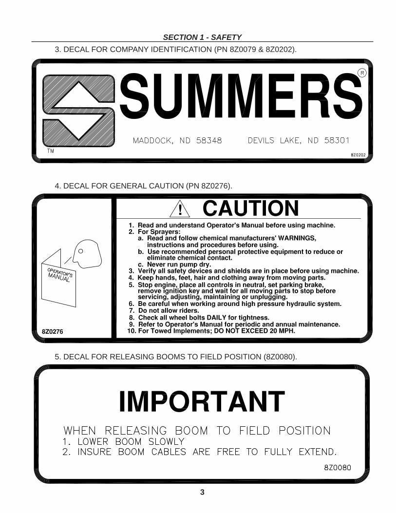
3. DECAL FOR COMPANY IDENTIFICATION (PN 8Z0079 & 8Z0202).
4. DECAL FOR GENERAL CAUTION (PN 8Z0276).
5. DECAL FOR RELEASING BOOMS TO FIELD POSITION (8Z0080).

4
SECTION 1 - SAFETY
6. DECAL WARNING SWING LOCK MUST BE ENGAGED (8Z0088).
7. ELECTROCUTION DANGER FOR 2-POINT SPRAYER (8Z0086).
8. PINCH POINT DECAL (8Z0087).
5
SECTION 1 - SAFETY
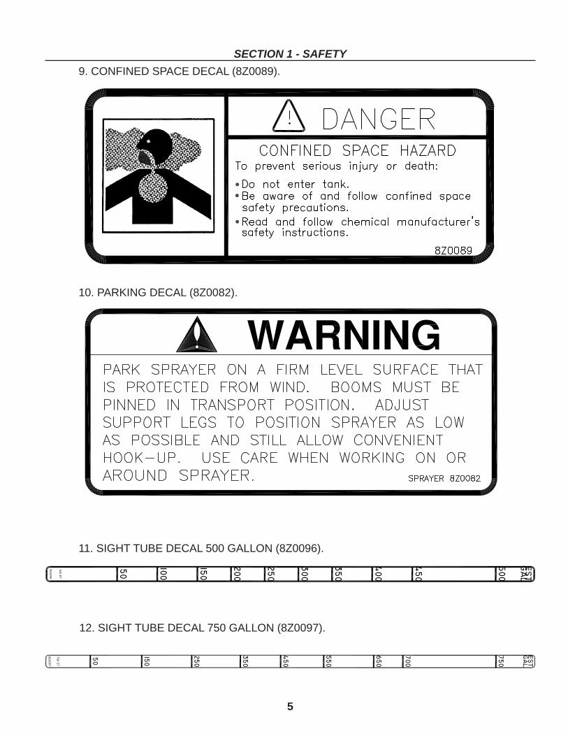
9. CONFINED SPACE DECAL (8Z0089).
10. PARKING DECAL (8Z0082).
11. SIGHT TUBE DECAL 500 GALLON (8Z0096).
12. SIGHT TUBE DECAL 750 GALLON (8Z0097).
6
SECTION 1 - SAFETY
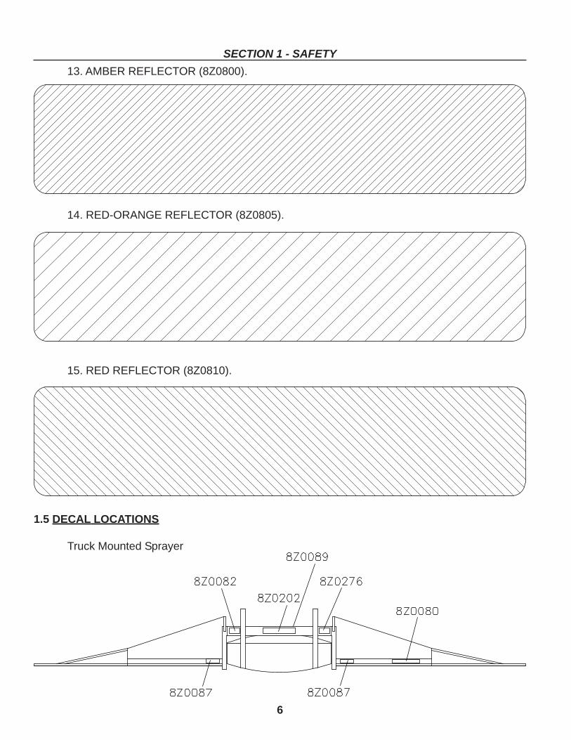
13. AMBER REFLECTOR (8Z0800).
14. RED-ORANGE REFLECTOR (8Z0805).
15. RED REFLECTOR (8Z0810).
1.5 DECAL LOCATIONS
Truck Mounted Sprayer
7
SECTION 1 - SAFETY
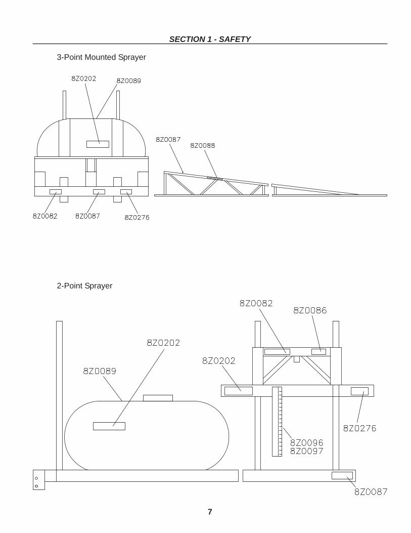
3-Point Mounted Sprayer
2-Point Sprayer

NOTES
8
9
SECTION 2 -GENERAL INFORMATION
2.1 STANDARD FEATURES
60 to 90 foot wetboom Truck Mounted Sprayers* Electric-Hydraulic tip lift.* Vertically adjustable spray height.* Tank is tapered to sump, fore, aft, and sideways.* Two section boom system with separate ball valves.* Hydraulically damped flex action booms with spring return.* Midmount booms for better visibility and weight distribution.* Sturdy truss-type two part boom system with separate spray ball valves.* 1 inch inside diameter aluminum wet boom with adjustable spray angle.* Self supporting stand with two side crank jacks for one man loading and unloading.* Raven 205 Control provides pressure reading and adjustment plus on/off control of each
boom.* 8 HP Honda engine with high capacity direct drive centrifugal Scot pump on sprayers 73-
90’.* 5.5 HP Honda engine with high capacity direct drive centrifugal Hypro pump on sprayers
60-70’.* Boom break away reduces damage should booms collide with obstacles causing exces-
sive boom pull.* Quick jet dripless triple pinwheel nozzles equipped with 80 degree XR (extended range)
stainless steel tips are factory spaced at 20”: 36 per 60’, 38 per 63’4”, 40 per 66’8”, 42per 70’, 44 per 73’4”, 46 per 76’8”, 48 per 80’, 50 per 83’4”, 52 per 86’8”, and 54 per 90’.
60 to 90 foot wetboom 2-Point Tractor Mounted Sprayers* Elliptical poly tank. * Tank level sight tube.* Sturdy truss-type booms. * Operator platform and ladder.* Double acting tip lift cylinders. * Three boom control ball valves.* Fits category II and III 3 point hitch. * Safety Light Package* Self supporting stand for one man hook up.* 30” of hydraulically adjustable spray height.* Row crop adjustable 12.5L x 15” 360 degree caster wheels.* Hydraulically damped flex action booms with spring return.* 1 inch inside diameter aluminum wet boom with adjustable spray angle.* Raven 205 Control provides pressure reading and adjustment plus on/off control of each
boom.* Boom break away reduces damage should booms collide with obstacles causing exces-
sive boom pull.* Quick jet dripless triple pinwheel nozzles equipped with 80 degree XR (extended range)
stainless steel tips are factory spaced at 20”: 36 per 60’, 38 per 63’4”, 40 per 66’8”, 42per 70’, 44 per 73’4”, 46 per 76’8”, 48 per 80’, 50 per 83’4”, 52 per 86’8”, and 54 per 90’.
10
SECTION 2 - GENERAL INFORMATION
3-Point Tractor Mounted* Boom mounted nozzles * Vertically adjustable spray height.* Self supporting stands for one man hook up. * Safety Light Package* Boom fold spring assist on sizes greater than 50’.* Three section boom system with separate ball valves.* Raven 205 Control provides pressure reading and adjustment plus on/off control of each
boom.* Boom break away reduces damage should booms collide with obstacles causing exces-
sive boom pull.* Quick jet dripless nozzles equipped with 80 degree XR (extended range) stainless steel
tips are factory spaced at 20”.
2.2 MAJOR OPTIONS60 to 90 foot wetboom Truck Mounted Sprayers
* Windshields.* Two tank sizes (350 or 500 gallon).* Ten application widths (60’, 63’4”, 66’8”, 70’, 73’4”, 76’8”, 80’, 83’4”, 86’8”, 90’).
60 to 90 foot wetboom 2-Point Tractor Sprayers* PTO or hydraulic pump.* Two tank sizes 500 or 750 gallon).* 11L x 15” 360 degree caster wheels.* 12.5L x 15” 360 degree caster wheels with lug tires.* Ten application widths (60’, 63’4”, 66’8”, 70’, 73’4”, 76’8”, 80’, 83’4”, 86’8”, 90’).* Chemical tank rinse system.* Chemical sprayer wash wand.
3-Point Tractor Sprayer* Hydraulic tip lift.* PTO or hydraulic pump.* Two tank sizes (300 to 500 gallon).* Five application widths (50’, 53’4”, 56’8”, 60’, and 66’)
2.3 OTHER OPTIONS* Hand wand option. * Foam marker.* Chemical fill wand. * Electric end nozzle.* 2 inch bottom fill kit * Chemical rinse wand.* Remote sprayer control. * Equal boom width option.* Middle boom ball valve kit. * Sprayer mounted radar sensor.* 110 degree XR stainless steel tips. * Clean water tank w/gloves and goggles.* End nozzle kit with manual shut-off valve.* Electric start engine on truck mounted sprayers.* Dual or triple swivel nozzles change spray tips with a simple twist.* Raven 450 Control provides computer controlled application based on ground speed.* Mix and fill kit with 1-1/4” built-in bottom fill provides foam reduced filling of sprayer tank
using chemical and/or water from nurse tank.

11
USING CHEMICALS?HIGH HAZARD REQUIRES:*goggles*respirator*avoid fumes*rubber gloves and skin protection
MODERATE HAZARD REQUIRES:*goggles*avoid fumes*rubber gloves and skin protection
LOW HAZARD REQUIRES:*avoid fumes*rubber gloves and skin protection
PROTECT YOURSELF!
1. REFER TO SIGNAL WORD AND REQUIRED PERSONALPROTECTIVE EQUIPMENT WHEN USING CHEMICALS.
2. ALWAYS READ AND FOLLOW CHEMICAL MANUFACTURERS’WARNINGS, INSTRUCTIONS AND PROCEDURES BEFOREUSING.
3. HANDLE CHEMICALS WITH EXTREME CARE.
4. IN CASE OF POISONING, GET IMMEDIATE MEDICAL ATTEN-TION. A CONTAINER LABEL MAY BE BENEFICIAL FORQUICK TREATMENT.
5. BE SAFE!
SECTION 3 - SPRAYER OPERATION
3.1 SPRAYER OPERATION SAFETY
1. READ AND UNDERSTAND Operator’sManual before using machine.
2. DO NOT ALLOW RIDERS OUTSIDE OF OPERATOR COMPARTMENT.3. ONLY TRANSPORT at a safe speed. Use caution when making corners or meeting traffic. Abrupt maneuvering
may cause uncontrollable results.4. USE a safety pin and clip on boom rest to secure boom when transporting. Booms must be folded and secured
during transport. SPRING LOADED LATCH IS NOT DESIGNED TO SECURE BOOMS DURING TRANSPORT.5. KEEP CHILDREN AWAY from chemicals and sprayer equipment.6. USE EXTREME CARE when cleaning, filling or making adjustments.7. ALWAYS READ chemical container label carefully and follow chemical manufacturers’ WARNINGS, instructions
and procedures before using.8. WHEN WORKING AROUND CHEMICALS:
CAUTIONREVIEW SECTION 3 SPRAYER OPERATION
SAFETY BEFORE PROCEEDING.
9. BE CAREFUL when working around a high pressure hydraulic system.10. ALWAYS make sure that pressure is relieved from hydraulic circuits before servicing or disconnecting any
hydraulic component.11. VERIFY all safety devices and shields are in place before using machine.12. KEEP hands, feet, hair and clothing away from moving parts.13. NEVER allow anyone to walk or work under a raised piece of equipment.
12
SECTION 3 - SPRAYER OPERATION
3.2 INITIAL SETUP AND ADJUSTMENT OF MECHANICAL SYSTEM
1. COMPLETE WARRANTY REGISTRATION CARDA. Complete and return WARRANTY REGISTRATION CARD located at the beginning of this manual. RE-
TURNING CARD ENTITLES YOU TO A FREE GIFT AND ASSURES THAT PRODUCT INFORMATIONBULLETINS WILL BE SENT DIRECTLY TO YOU.
B. Complete the OWNER REGISTRATION also located at the beginning of this manual. REMEMBER TOBRING OWNER REGISTER INFORMATION WHEN ORDERING PARTS.
2. PREPARE TO LOAD SPRAYER.
A. TRUCK MOUNTED SPRAYERS1. Service gasoline engine as recommended by manufacturer.2. Check bands securing tank for tightness.3. Check all hose connections.4. Check oil level in Electric-Hydraulic tip lift motor.5. Locate or drill a hole in left front corner of the truck bed to attach the
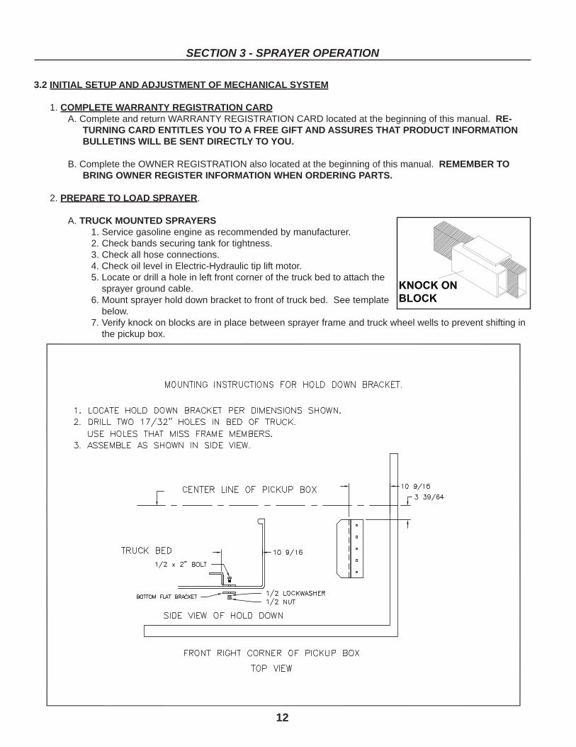
sprayer ground cable.6. Mount sprayer hold down bracket to front of truck bed. See template
below.7. Verify knock on blocks are in place between sprayer frame and truck wheel wells to prevent shifting in
the pickup box.
13
SECTION 3 - SPRAYER OPERATION
B. TRACTOR MOUNTED SPRAYERS1. Check bands securing tank for tightness.2. Check all hose connections.3. Inspect hydraulic hoses for damage and fraying.4. Inspect sprayer mount for loose or missing fasteners.
3. LOAD SPRAYER
A. TRUCK MOUNTED SPRAYER1. Retract jacks and remove. Lift rear of sprayer and pin legs in the up position.2. Secure Skid with rear box locks provided at the two corners.3. Make wiring connections per diagram on page 15.
a. one battery positive connection.b. one battery switched and fused connection.c. one ground connection.
4. To connect tip lift electrical system to pickup electrical system follow these steps:a. Attach ground cable to the hole in pickup box using a 3/8” bolt and nut.b. Route power cord to engine compartment and connect to positive battery terminal or main battery
power distribution source.c. Connect single small RED wire to a SWITCHED and FUSED terminal in the pickup fuse box. This
may require additional wire.
WARNING!POWER CORD MUST NOT CONTACT EXHAUST OR MOVING PARTS. THE CABLE HAS NO CIRCUIT PROTEC-TION AND ANY DAMAGE TO THE CABLE INSULATION COULD RESULT IN PERMANENT BATTERY DAMAGE.
CAUTION!DO NOT CONNECT RED WIRE TO ANY NON-SWITCHED TERMINAL. AN INCORRECT POWER SUPPLY WILLPERMIT TIP LIFT OPERATION AT ANY TIME WITHOUT THE IGNITION SWITCH IN THE ON POSITION ANDCOULD RESULT IN SERIOUS BODILY INJURY OR DAMAGE TO THE SPRAYER.
IMPORTANT!TO PREVENT DAMAGE TO PLUMBING COMPO-NENTS FROM FREEZING, THE SUCTION ANDAGITATION HOSES ON 3-POINT SPRAYERSHAVE NOT BEEN CONNECTED. PRIOR TOUSING THE SPRAYER, THESE HOSES MUSTBE INSTALLED AND SECURED, WITH HOSECLAMPS, TO THE LOWER TANK FITTINGS.
HYDRAULIC TIP-LIFT3-POINT SPRAYERS ONLY!
SAFETY TRANSPORT LOCKS (Part Number8G7170, painted red) HAVE BEEN INSTALLEDON THE TIP LIFT CYLINDERS TO PREVENTPOSSIBLE INJURY WHILE UNFOLDING THEBOOMS BEFORE FULLY CHARGING THE CYL-INDERS ON SPRAYER.
B. TRACTOR MOUNTED SPRAYERS1. Connect sprayer to 3-point of tractor.2. Secure 3-point latches.3. Unfold booms to field position.4. Remove Safety Transport Locks on dry boom
3-point only.5. Connect TIP-LIFT hoses to tractor remotes.6. Fully charge cylinders by raising each boom
slowly.7. Hook up PTO pump if equipped.8. Make other hydraulic connections.
HYDRAULIC PUMP NOTES:Many tractor hydraulic systems route return lines through filters or other restrictive elements which can cause an increase inreturn circuit pressure. Hypro’s hydraulic motor oil seals are designed to withstand 300 PSI continuous pressure. However,whenever possible, it is recommended to utilize either a standard (or purchase an optional) low pressure return circuit. Thiswill allow for less oil heat generation, lower horsepower consumption, and longer oil seal life. Consult with your tractor manu-facturer to see if your tractor is or can be equipped in this way.
The Return (or Tank) ports on Hypro hydraulic motors are equipped with an anti-reversing check valve. This is to prevent themotor from accidentally being operated backwards. Backward operation of the motor will cause almost immediate oil sealfailure. Do Not Remove Check Valve.
HM2 and HM4 models of Hypro’s hydraulic motor driven centrifugal pumps can be equipped with a metering orifice in the inletport. The orifice is intended to be used on older model tractors with Closed Center systems that do not have flow control
14
SECTION 3 - SPRAYER OPERATION
HYDRAULIC VERTICAL BOOM ADJUSTMENT SPRAYERS!VERTICAL BOOM HEIGHT MUST NOT BE ACTIVATED WITH THE BOOMS IN THE FOLDED POSITION ORDAMAGE TO SPRAYER WILL RESULT. VERTICAL ADJUSTMENT MUST ONLY BE PERFORMED WITH THEBOOMS IN FIELD POSITION.
IMPORTANT!BEFORE ACTIVATING SPRAY PUMP HYDRAULIC SYSTEM VERIFY DIRECTION OF OIL FLOW IS CORRECT. OILMUST FLOW INTO THE PRESSURE PORT OF HYDRAULIC MOTOR. THIS CAN BE CHECKED BY MOMEN-TARILY ACTIVATING THE HYDRAULIC SYSTEM. THE HOSE LEADING TO THE PRESSURE PORT SHOULDFLEX OR STIFFEN WHEN SYSTEM IS ACTIVATED. IF WRONG HOSE FLEXES, EITHER REVERSE HOSES ATTHE TRACTOR OUTLET OR MOVE HYDRAULIC LEVER IN OPPOSITE DIRECTION. A CHECK VALVE INSTALLEDON THE TANK SIDE OF THE MOTOR PREVENTS OIL FROM FLOWING THROUGH THE MOTOR IN THE WRONGDIRECTION.
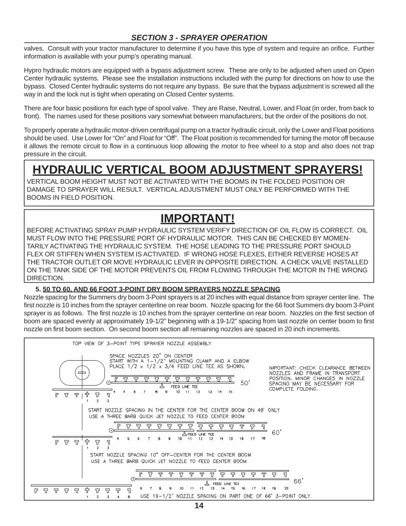
5. 50 TO 60, AND 66 FOOT 3-POINT DRY BOOM SPRAYERS NOZZLE SPACINGNozzle spacing for the Summers dry boom 3-Point sprayers is at 20 inches with equal distance from sprayer center line. Thefirst nozzle is 10 inches from the sprayer centerline on rear boom. Nozzle spacing for the 66 foot Summers dry boom 3-Pointsprayer is as follows. The first nozzle is 10 inches from the sprayer centerline on rear boom. Nozzles on the first section ofboom are spaced evenly at approximately 19-1/2” beginning with a 19-1/2” spacing from last nozzle on center boom to firstnozzle on first boom section. On second boom section all remaining nozzles are spaced in 20 inch increments.
valves. Consult with your tractor manufacturer to determine if you have this type of system and require an orifice. Furtherinformation is available with your pump’s operating manual.
Hypro hydraulic motors are equipped with a bypass adjustment screw. These are only to be adjusted when used on OpenCenter hydraulic systems. Please see the installation instructions included with the pump for directions on how to use thebypass. Closed Center hydraulic systems do not require any bypass. Be sure that the bypass adjustment is screwed all theway in and the lock nut is tight when operating on Closed Center systems.
There are four basic positions for each type of spool valve. They are Raise, Neutral, Lower, and Float (in order, from back tofront). The names used for these positions vary somewhat between manufacturers, but the order of the positions do not.
To properly operate a hydraulic motor-driven centrifugal pump on a tractor hydraulic circuit, only the Lower and Float positionsshould be used. Use Lower for “On” and Float for “Off”. The Float position is recommended for turning the motor off becauseit allows the remote circuit to flow in a continuous loop allowing the motor to free wheel to a stop and also does not trappressure in the circuit.
15
SECTION 3 - SPRAYER OPERATION
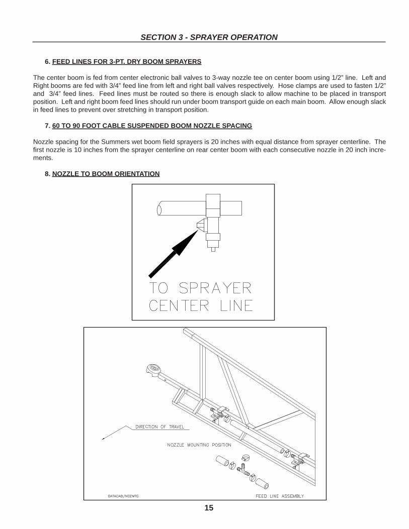
6. FEED LINES FOR 3-PT. DRY BOOM SPRAYERS
The center boom is fed from center electronic ball valves to 3-way nozzle tee on center boom using 1/2” line. Left andRight booms are fed with 3/4” feed line from left and right ball valves respectively. Hose clamps are used to fasten 1/2”and 3/4” feed lines. Feed lines must be routed so there is enough slack to allow machine to be placed in transportposition. Left and right boom feed lines should run under boom transport guide on each main boom. Allow enough slackin feed lines to prevent over stretching in transport position.
7. 60 TO 90 FOOT CABLE SUSPENDED BOOM NOZZLE SPACING
Nozzle spacing for the Summers wet boom field sprayers is 20 inches with equal distance from sprayer centerline. Thefirst nozzle is 10 inches from the sprayer centerline on rear center boom with each consecutive nozzle in 20 inch incre-ments.
8. NOZZLE TO BOOM ORIENTATION
16
SECTION 3 - SPRAYER OPERATION
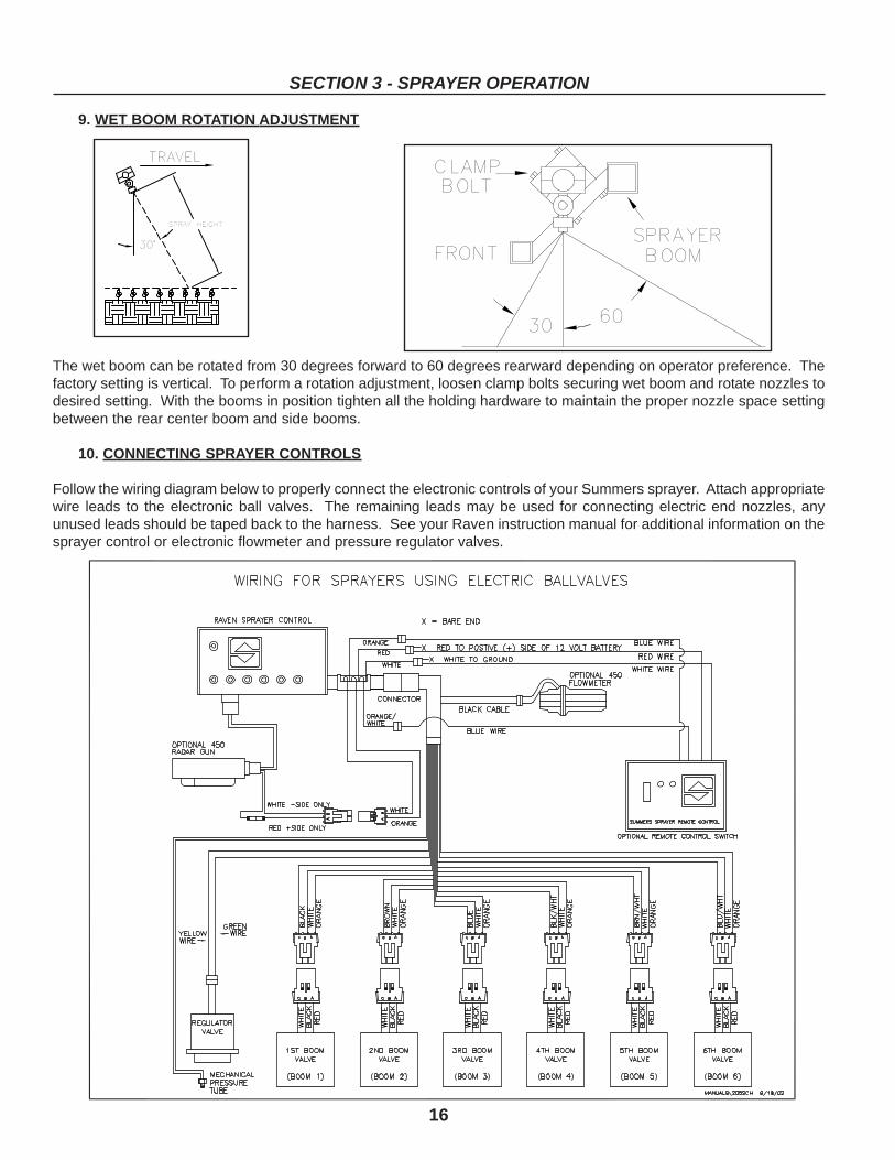
9. WET BOOM ROTATION ADJUSTMENT
The wet boom can be rotated from 30 degrees forward to 60 degrees rearward depending on operator preference. Thefactory setting is vertical. To perform a rotation adjustment, loosen clamp bolts securing wet boom and rotate nozzles todesired setting. With the booms in position tighten all the holding hardware to maintain the proper nozzle space settingbetween the rear center boom and side booms.
10. CONNECTING SPRAYER CONTROLS
Follow the wiring diagram below to properly connect the electronic controls of your Summers sprayer. Attach appropriatewire leads to the electronic ball valves. The remaining leads may be used for connecting electric end nozzles, anyunused leads should be taped back to the harness. See your Raven instruction manual for additional information on thesprayer control or electronic flowmeter and pressure regulator valves.
17
SECTION 3 - SPRAYER OPERATION
SCS-205 Control has Mechanical Pressure Sensing (Less Pressure Transducer).12’ extension cable assemblies are available.
Order PN 8A1285 for SCS-205 Control.Order PN 8A4340 for SCS-450 Control.
11. ELECTRIC - HYDRAULIC TIP LIFT ON TRUCK SPRAYERS
The electric-hydraulic tip lift is a self-contained hydraulic system. It requires little maintenance other than clean oil filled tothe proper level, a good 12-volt power source, and a secure ground.
3.3 INITIAL SETUP OF SPRAY SYSTEM
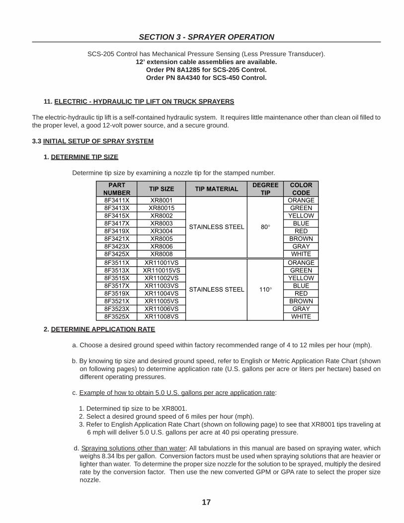
1. DETERMINE TIP SIZE
Determine tip size by examining a nozzle tip for the stamped number.
2. DETERMINE APPLICATION RATE
a. Choose a desired ground speed within factory recommended range of 4 to 12 miles per hour (mph).
b. By knowing tip size and desired ground speed, refer to English or Metric Application Rate Chart (shownon following pages) to determine application rate (U.S. gallons per acre or liters per hectare) based ondifferent operating pressures.
c. Example of how to obtain 5.0 U.S. gallons per acre application rate:
1. Determined tip size to be XR8001.2. Select a desired ground speed of 6 miles per hour (mph).3. Refer to English Application Rate Chart (shown on following page) to see that XR8001 tips traveling at
6 mph will deliver 5.0 U.S. gallons per acre at 40 psi operating pressure.
d. Spraying solutions other than water: All tabulations in this manual are based on spraying water, whichweighs 8.34 lbs per gallon. Conversion factors must be used when spraying solutions that are heavier orlighter than water. To determine the proper size nozzle for the solution to be sprayed, multiply the desiredrate by the conversion factor. Then use the new converted GPM or GPA rate to select the proper sizenozzle.
�����
�������� ��� �����������
�������
���
������
����
������� ���� ��� �
������� ����� ����
������� ���� �����
������� ���� ����
������� ���� ���
������� ���� ����
������� ���� ���
������� ���� �����
������� ������� ��� �
������� �������� ����
������� ������� �����
������� ������� ����
������� ������� ���
������� ������� ����
������� ������� ���
������� ������� �����
���������������
��������������� ��
���
���������� ������� �� ��� �
�!"#��$
���#�!%����
&" ��!%���������� �������
�� ��� �
�!"#��$
���#�!%����
&" ��!%
� �!"# �$%&�'(!!)* �� �� � ���!"# �$%&�'(!!)* � �� � ��
� �!"# �$%&�'(!!)* �� �� �� �!"# �$%&�'(!!)* � �� � ��
� ���!"# �$%&�'(!!)*�+�
,(-%&� � �� �!"# �$%&�'(!!)* � �� � �
� �!"# �$%&�'(!)* � � � � �� �!"# �$%&�'(!!)* � �� � �
� �!"# �$%&�'(!!)* � � � �
�����.���/�
���
�//��
��/�
.�������
.��
�����
.���0�����
�.���
������1
�2��3
�����
.����4��
1���0.�
� �� ��3 � �
� � ��3 � �
� �� ��3 � �
� �� ��3 � �
� � ��3 � �
� �� ��3 � �
� �� �3 � �
� � ��3 � �
� �� ��3 �� �
� � � ��3 �� �
� � � ��3 �� �
� � �� ��3 �� �
� � �� ���3 �� �
� � � ���3 �� �
� � �� ���3 �� �
��
��
4��
4��
�� 4�
��
��
4��
4��
����������� �������'���
�� 4�
��� 4�
18
SECTION 3 - SPRAYER OPERATION
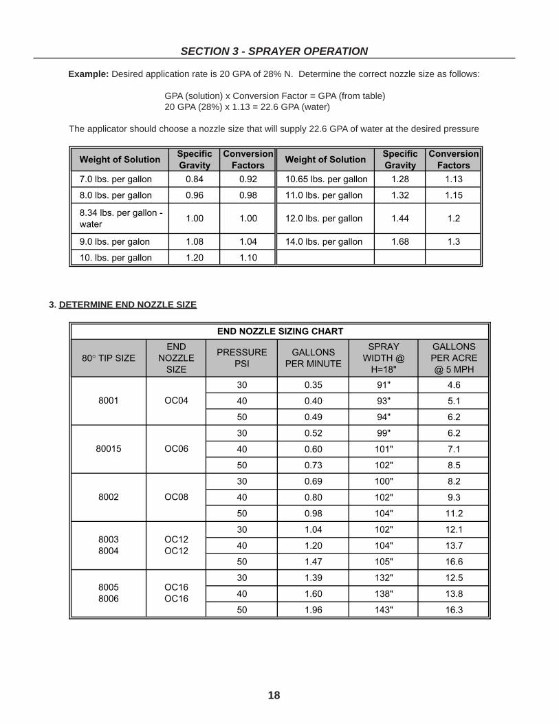
Example: Desired application rate is 20 GPA of 28% N. Determine the correct nozzle size as follows:
GPA (solution) x Conversion Factor = GPA (from table)20 GPA (28%) x 1.13 = 22.6 GPA (water)
The applicator should choose a nozzle size that will supply 22.6 GPA of water at the desired pressure
3. DETERMINE END NOZZLE SIZE

���������������� ������� ����
���� ��� ����������������� ��������������� ����� ���������������
��� ��������
���������������������
��
����
��� ��!"#�$���%%���!��
���������%&'!��
�(�
�)�
�*�
�+�
�$��
�$��
�$(�
���)�&�+�
�,�)�
�,���
���)�
���,�
�$�+�
�$�(�
����
���*�&�-�
�.���
�,�(�
�,���
���)�
���$�
�$�+�
�,��
���-�&�$$�
�(�,�
�.�(�
�,�*�
�,���
���)�
���$�
�.��
��$��&�$,�
�(�-�
�(���
�.���
�,�*�
�,���
���(�
�(��
��$$�&�$.�
�)�(�
�(�.�
�.�*�
�.�$�
�,�,�
���*�
�)��
��$��&�$(�
�*�$�
�(�-�
�(�$�
�.�(�
�,�)�
�,���
�/*(�
��$.�&�$+�
�+�,�
�)�-�
�(�-�
�(���
�.���
�,�(�
����
+��$�$$��$����0��
�$���'�12�������
�/-��
��$(�&�$-�
�+�-�
�*�.�
�)�.�
�(�)�
�.�(�
�,�*�
�$(�
���-�&�$��
�(�,�
�.�(�
�,�+�
�,�,�
���*�
���,�
����
��$$�&�$.�
�)�(�
�(�.�
�.�*�
�.�$�
�,���
���)�
�,��
��$,�&�$*�
�*�*�
�)�.�
�(�(�
�.�+�
�,�-�
�,���
�.��
��$(�&�$-�
�+�-�
�*�.�
�)�.�
�(�)�
�.�(�
�,�*�
�(��
��$*�&����
�$��$�
�+�.�
�*���
�)�,�
�(���
�.���
�)��
��$+�&��,�
�$��*�
�+�-�
�*�)�
�)�*�
�(�(�
�.�)�
�/*(�
���$�&��*�
�$��(�
�$��.�
�+�-�
�*�+�
�)���
�(���
����
+��$(�$$��$(�������
�$���'�12�������
�/-��
���,�&��-�
�$,�*�
�$$�.�
�-�+�
�+�(�
�)�+�
�(�*�
�$(�
��$��&�$(�
�*�$�
�(�-�
�(�$�
�.�(�
�,�(�
�,���
����
��$.�&�$+�
�+�,�
�)�-�
�(�-�
�(���
�.���
�,�(�
�,��
��$*�&����
�$��$�
�+�.�
�*���
�)�,�
�(���
�.���
�.��
�����&��)�
�$$�-�
�-�-�
�+�(�
�*�.�
�(�-�
�(���
�(��
�����&��+�
�$,�$�
�$��-�
�-�,�
�+���
�)�(�
�(�.�
�)��
���.�&�,$�
�$.�,�
�$$�-�
�$����
�+�-�
�*�$�
�(�-�
�/*(�
���*�&�,(�
�$)���
�$,�.�
�$$�(�
�$����
�+���
�)�*�
����
+����$$����3����4�
�(��
�'�12���5�
�/-��
��,��&�,+�
�$*�+�
�$.�-�
�$��*�
�$$�$�
�+�-�
�*�.�
�$(�
��$+�&��,�
�$��*�
�+�-�
�*�)�
�)�*�
�(�,�
�.�(�
����
���$�&��*�
�$��(�
�$��.�
�+�-�
�*�+�
�)���
�(���
�,��
���)�&�,,�
�$(�.�
�$��-�
�$$���
�-�*�
�*�*�
�)�.�
�.��
��,��&�,+�
�$*�+�
�$.�-�
�$��*�
�$$�$�
�+�-�
�*�.�
�(��
��,.�&�..�
������
�$)�+�
�$.�.�
�$��)�
�$��$�
�+�.�
�)��
��,*�&�.*�
������
�$+�,�
�$(�*�
�$,�*�
�$$���
�-���
�/*(�
��.$�&�(��
��.���
������
�$*�.�
�$(���
�$����
�$��$�
����
+��,�$$��,�6�7���(��
�'�12���5�
�/-��
��.(�&�(+�
��*���
������
�$-�$�
�$)�*�
�$,�.�
�$$�$�
�$(�
���.�&�,$�
�$.�,�
�$$�-�
�$����
�+�-�
�*�$�
�(�-�
����
���+�&�,)�
�$)�)�
�$,�-�
�$$�-�
�$��.�
�+�,�
�)�-�
�,��
��,(�&�.(�
��$���
�$*�,�
�$.�-�
�$,���
�$��.�
�+�*�
�.��
��.��&�($�
��.���
�$-�+�
�$*���
�$.�-�
�$$�-�
�-�-�
�(��
��.(�&�(+�
��*���
������
�$-�$�
�$)�*�
�$,�.�
�$$�$�
�)��
��.-�&�),�
��-���
��.���
��$���
�$+���
�$.�)�
�$��$�
�/*(�
��((�&�*��
�,,���
��*���
��,���
������
�$)�,�
�$,�)�
����
+��.�$$��.���5��(��
'�12���5�
�/-��
��)��&�**�
�,)���
�,����
��(���
������
�$*�+�
�$.�-�
�$(�
��,$�&�.��
�$+�.�
�$(�,�
�$,���
�$$�(�
�-���
�*�*�
����
��,(�&�.(�
��$���
�$*�,�
�$.�-�
�$,���
�$��.�
�+�*�
�,��
��.,�&�((�
��)���
��$���
�$+���
�$)���
�$��+�
�$��)�
�.��
��(��&�).�
�,����
��(���
��$���
�$+�)�
�$.�)�
�$��.�
�(��
��()�&�*��
�,,���
��+���
��.���
��$���
�$)�)�
�$,�-�
�)��
��)$�&�*+�
�,)���
�,����
��)���
��,���
�$+�$�
�$(�$�
�/*(�
��)+�&�+*�
�.����
�,.���
��-���
��(���
������
�$)�+�
����
+��(�$$��(�6��4��
�(��
'�12���5�
�/-��
��*(�&�-)�
�.(���
�,*���
�,����
��+���
����,�
�$+�)�
�$(�
��,*�&�.*�
������
�$+�,�
�$(�*�
�$,�*�
�$$���
�-���
����
��.��&�(.�
��(���
��$���
�$*�+�
�$(�)�
�$��(�
�$��.�
�,��
��(��&�)*�
�,$���
��)���
������
�$-�,�
�$(�.�
�$��-�
�.��
��)��&�**�
�,)���
�,����
��(���
������
�$*�+�
�$.�-�
�(��
��)*�&�+)�
�.����
�,,���
��+���
��(���
�$-�-�
�$)�)�
���
+��)�$$��)����#��(��
'�12���5�
�)��
��*,�&�-(�
�..���
�,)���
�,$���
��*���
������
�$+���
�$(�
��.-�&�),�
��-���
��.���
��$���
�$+���
�$.�(�
�$����
����
��(*�&�*,�
�,.���
��+���
��.���
��$���
�$)�+�
�$.���
�,��
��)-�&�++�
�.$���
�,.���
��-���
��)���
��$���
�$*���
�.��
��+�&�$���
�.+���
�.����
�,.���
�,����
��.���
�$-�+�
�(��
��+-�&�$$,�(�
�(,���
�..���
�,+���
�,,���
��*���
������
��
�+��+�$$��+�82!"��
�(��
'�12���5�
�)��
��-+�&�$�(�
�(+���
�.-���
�.����
�,)���
��-���
��.���
/�����6�� 9 ��������� �� ��� �� ��:���� ���� ���� �� �������)������ � ���6�� ����8�� ��;�+�,.�6&������
+<$$�*�����(&-)�19
SECTION 3 - SPRAYER OPERATION

� ���������������� ������� ���
���� ��� ������������������ ���� �� ���� ��� ���� ����(�+�'�=���>���������
��� ����?�&���=���>�
���������������������
��
?��&$���=���>�
��� ��!"#�$���%%���!��&'!��
�+�=(>�
�$��=)��>�
�$��=*�(>�
�$.�=+�*>�
�$)�=-�->�
�$+�=$$��>�
�$���=$.�(>�
���,�
�,.�(�
��*�)�
��,���
�$-�*�
�$*�,�
�$(�,�
�$�(�=�$�+>�
���+�
�.����
�,,�)�
��+���
��.���
��$���
�$+�*�
�����=�-��>�
��,��
�.+���
�,+�.�
�,����
��*�.�
��.���
��$�,�
���(�=,)�,>�
��,)�
�(.���
�.,���
�,)���
�,��-�
��*���
��.���
�,���=.,�(>�
��,-�
�(+�(�
�.)�+�
�,-���
�,,�.�
��-�,�
��)���
�,�(�=(��*>�
��.��
�),���
�(��.�
�.����
�,)���
�,$�(�
��+���
�.���=(+��>�
��.(�
�)*�(�
�(.���
�.(���
�,+�)�
�,,�+�
�,����
�/(���=*��(>�
��(��
�*(���
�)����
�(����
�.��-�
�,*�(�
�,,�,�
����
+��$�$$��$����0��
�$���'�12�������
�/)���=+*��>�
��((�
�+��(�
�))���
�((���
�.*�$�
�.$�,�
�,)�*�
�$���=$.�(>�
��,.�
�($���
�.��+�
�,.���
��-�$�
��(�(�
����*�
�$�(�=�$�+>�
��.��
�),���
�(��.�
�.����
�,)���
�,$�(�
��+���
�����=�-��>�
��.+�
�*����
�(*�)�
�.+���
�.$�$�
�,)���
�,����
���(�=,)�,>�
��(.�
�+$���
�).�+�
�(.���
�.)�,�
�.��(�
�,)���
�,���=.,�(>�
��(-�
�++�(�
�*��+�
�(-���
�(��)�
�..�,�
�,-�,�
�,�(�=(��*>�
��).�
�-)���
�*)�+�
�).���
�(.�-�
�.+���
�.��*�
�.���=(+��>�
��)+�
�$�����
�+$�)�
�)+���
�(+�,�
�($���
�.(�,�
�/(���=*��(>�
��*)�
�$$.���
�-$���
�*)���
�)(�$�
�(*���
�(��*�
����
+��$(�$$��$(�������
�$���'�12�������
�/)���=+*��>�
��+,�
�$�(���
�--�)�
�+,���
�*$�$�
�)��,�
�((�,�
�$���=$.�(>�
��.)�
�)-���
�((���
�.)���
�,-�.�
�,.�(�
�,��*�
�$�(�=�$�+>�
��()�
�+.���
�)*���
�()���
�.+���
�.����
�,*�,�
�����=�-��>�
��)(�
�-*�(�
�*+���
�)(���
�((�*�
�.+�+�
�.,�,�
���(�=,)�,>�
��*��
�$�+���
�+)�.�
�*����
�)$�*�
�(.���
�.+���
�,���=.,�(>�
��*-�
�$$-���
�-.�+�
�*-���
�)*�*�
�(-�,�
�(��*�
�,�(�=(��*>�
��+(�
�$�+���
�$�����
�+(���
�*��-�
�),�+�
�()�*�
�.���=(+��>�
��-$�
�$,*���
�$�-���
�-$���
�*+���
�)+�,�
�)��*�
�/(���=*��(>�
�$����
�$(,���
�$�����
�$�����
�+*�.�
�*)�(�
�)+���
����
+����$$����3����4�
�(��
'�12���5�
�/)���=+*��>�
�$�$��
�$)+���
�$,.���
�$$����
�-)���
�+.���
�*.�*�
�$���=$.�(>�
��)+�
�$�����
�+$�)�
�)+���
�(+�,�
�($���
�.(�,�
�$�(�=�$�+>�
��+,�
�$�(���
�--�)�
�+,���
�*$�$�
�)��,�
�((�,�
�����=�-��>�
��-)�
�$..���
�$$(���
�-)���
�+��,�
�*����
�).���
���(�=,)�,>�
�$��+�
�$)����
�$,����
�$�+���
�-��)�
�+$���
�*����
�,���=.,�(>�
�$�$+�
�$**���
�$.����
�$$+���
�$�$���
�++�(�
�*+�*�
�,�(�=(��*>�
�$��*�
�$-$���
�$(����
�$�*���
�$�-���
�-(�,�
�+.�*�
�.���=(+��>�
�$�,)�
���.���
�$),���
�$,)���
�$$*���
�$�����
�-��*�
�/(���=*��(>�
�$�(��
���+���
�$+����
�$(����
�$,����
�$$.���
�$�$���
����
+��,�$$��,�6�7���(��
'�12���5��
�/)���=+*��>�
�$�)*�
��($���
�������
�$)*���
�$.,���
�$�(���
�$$$���
�$���=$.�(>�
��-$�
�$,*���
�$�-���
�-$���
�*+���
�)+�,�
�)��*�
�$�(�=�$�+>�
�$�$��
�$)+���
�$,.���
�$$����
�-)���
�+.���
�*.�*�
�����=�-��>�
�$��-�
�$-.���
�$((���
�$�-���
�$$$���
�-)�+�
�+)���
���(�=,)�,>�
�$�..�
��$)���
�$*,���
�$..���
�$�,���
�$�+���
�-)���
�,���=.,�(>�
�$�(+�
��,*���
�$-����
�$(+���
�$,(���
�$$-���
�$�(���
�,�(�=(��*>�
�$�*$�
��(*���
���(���
�$*$���
�$.*���
�$�+���
�$$.���
�.���=(+��>�
�$�+��
��*,���
��$+���
�$+����
�$()���
�$,*���
�$�$���
�/(���=*��(>�
����.�
�,�)���
��.(���
���.���
�$*(���
�$(,���
�$,)���
����
+��.�$$��.���5��(��
'�12���5�
�/)���=+*��>�
����,�
�,,(���
��)+���
���,���
�$-$���
�$)*���
�$.-���
�$���=$.�(>�
�$�$.�
�$*$���
�$,*���
�$$.���
�-*�*�
�+(�(�
�*)���
�$�(�=�$�+>�
�$�,-�
���-���
�$)*���
�$,-���
�$$-���
�$�.���
�-��*�
�����=�-��>�
�$�)$�
��.����
�$-,���
�$)$���
�$,+���
�$�$���
�$�*���
���(�=,)�,>�
�$�+��
��*����
��$)���
�$+����
�$(.���
�$,(���
�$�����
�,���=.,�(>�
�$�-*�
��-)���
��,)���
�$-*���
�$)-���
�$.+���
�$,$���
�,�(�=(��*>�
���$,�
�,�����
��()���
��$,���
�$+,���
�$)����
�$.����
���.���=(+��>�
����*�
�,.$���
��*����
���*���
�$-(���
�$*����
�$($���
�/(���=*��(>�
���(.�
�,+$���
�,�(���
��(.���
��$+���
�$-$���
�$)-���
����
+��(�$$��(�6��4��
�(��
'�12���5�
�/)���=+*��>�
���*-�
�.$-���
�,,(���
��*-���
��,-���
���-���
�$+)���
�$���=$.�(>�
�$�,*�
���)���
�$).���
�$,*���
�$$*���
�$�,���
�-$�,�
�$�(�=�$�+>�
�$�)+�
��(����
�������
�$)+���
�$..���
�$�)���
�$$����
�����=�-��>�
�$�-.�
��-$���
��,,���
�$-.���
�$))���
�$.)���
�$�-���
���(�=,)�,>�
���$)�
�,�.���
��(-���
��$)���
�$+(���
�$)����
�$..���
�,���=.,�(>�
���,*�
�,()���
��+.���
��,*���
���,���
�$*+���
�$(+���
�,�(�=(��*>�
���()�
�,+.���
�,�*���
��()���
��$-���
�$-����
�$*$���
���
+��)�$$��)����#��(��
'�12���5�
�.���=(+��>�
���*.�
�.$$���
�,�-���
��*.���
��,(���
���)���
�$+,���
�$���=$.�(>�
�$�+��
��*,���
��$+���
�$+����
�$()���
�$,*���
�$�$���
�$�(�=�$�+>�
����,�
�,,(���
��)+���
���,���
�$-$���
�$)*���
�$.-���
�����=�-��>�
���(+�
�,+*���
�,$����
��(+���
���$���
�$-.���
�$*����
���(�=,)�,>�
���++�
�.,����
�,.)���
��++���
��.*���
��$)���
�$-����
�,���=.,�(>�
�,�$)�
�.*.���
�,*-���
�,$)���
��*$���
��,*���
��$$���
�,�(�=(��*>�
�,�.$�
�($����
�.�-���
�,.$���
��-����
��()���
���*���
���
+��+�$$��+�82!"��
�(��
'�12���5�
�.���=(+��>�
�,�)(�
�(.+���
�.,+���
�,)(���
�,$,���
��*.���
��.,���
� /�����6�� 9 ��������� �� ��� �� ��:���� ���� ���� �� �������.�?���� � � � �6�� ����8�� ��;�$��0'&�',���
�����+<$$�*�����(&-)�20
SECTION 3 - SPRAYER OPERATION
21
SECTION 3 - SPRAYER OPERATION
3.4 TESTING AND ADJUSTMENT OF SPRAYER SYSTEM
1. ADD WATER TO MAIN TANK
Add approximately 150 gallons of water to main tank through optional bottom fill kit or through top fill well. With waterin the tank verify that tank straps are secure.
2. PRIME SPRAYER SYSTEM PUMPa. Prime PTO driven pump
1. Engage tractor PTO system and increase to normal field PTO speed in order to circulate water from thetank to the pump and back to the tank again through the agitators. Immediately verify agitator flow bylooking through top fillwell.
2. Disengage tractor PTO system.
b. Prime hydraulically driven pump:
1. Engage tractor hydraulic system and increase to normal field rpm speed in order to circulate water from thetank to the pump and back to the tank again through the agitators. Immediately verify agitator flow bylooking through top fillwell.
2. Disengage tractor hydraulic system by moving hydraulic lever to float position. This allows pump to coastto a stop.
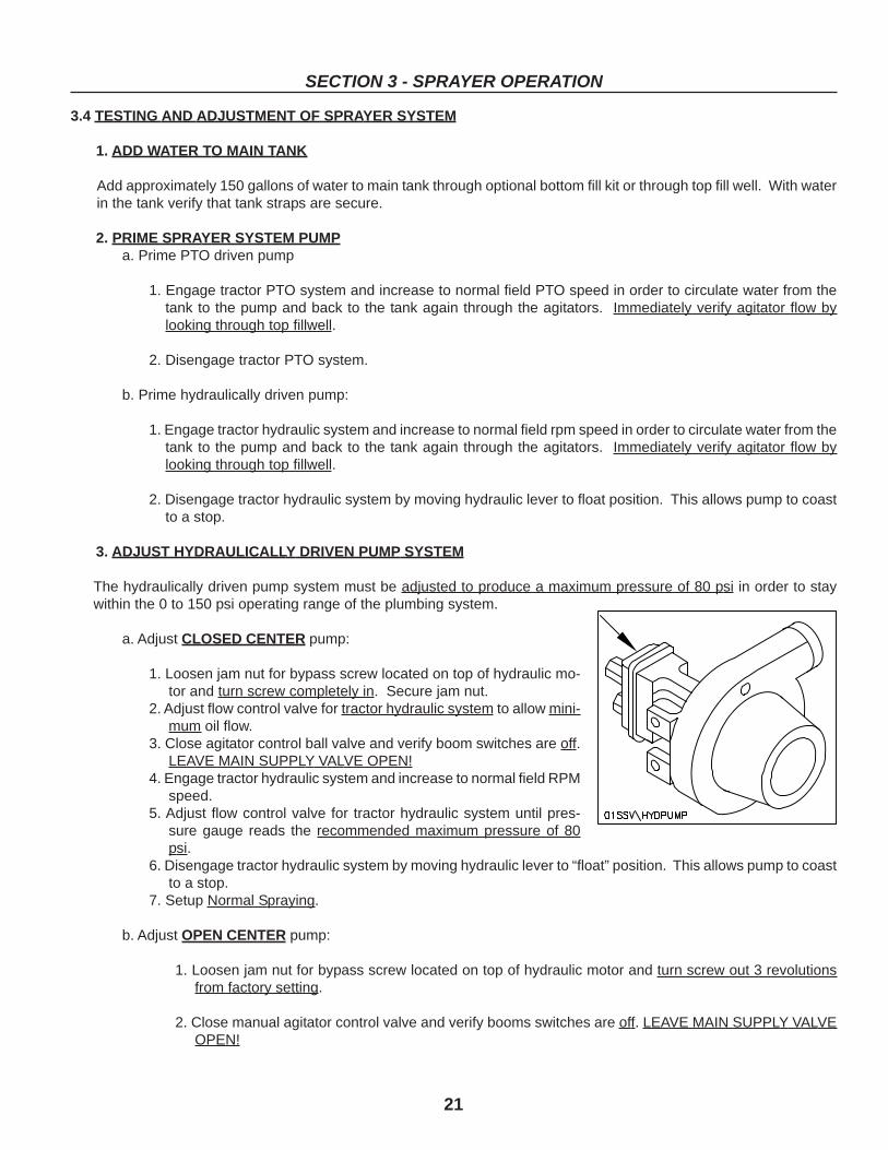
3. ADJUST HYDRAULICALLY DRIVEN PUMP SYSTEM
The hydraulically driven pump system must be adjusted to produce a maximum pressure of 80 psi in order to staywithin the 0 to 150 psi operating range of the plumbing system.
a. Adjust CLOSED CENTER pump:
1. Loosen jam nut for bypass screw located on top of hydraulic mo-tor and turn screw completely in. Secure jam nut.
2. Adjust flow control valve for tractor hydraulic system to allow mini-mum oil flow.
3. Close agitator control ball valve and verify boom switches are off.LEAVE MAIN SUPPLY VALVE OPEN!
4. Engage tractor hydraulic system and increase to normal field RPMspeed.
5. Adjust flow control valve for tractor hydraulic system until pres-sure gauge reads the recommended maximum pressure of 80psi.
6. Disengage tractor hydraulic system by moving hydraulic lever to “float” position. This allows pump to coastto a stop.
7. Setup Normal Spraying.
b. Adjust OPEN CENTER pump:
1. Loosen jam nut for bypass screw located on top of hydraulic motor and turn screw out 3 revolutionsfrom factory setting.
2. Close manual agitator control valve and verify booms switches are off. LEAVE MAIN SUPPLY VALVEOPEN!
22
SECTION 3 - SPRAYER OPERATION
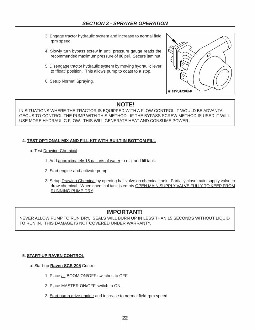
3. Engage tractor hydraulic system and increase to normal fieldrpm speed.
4. Slowly turn bypass screw in until pressure gauge reads therecommended maximum pressure of 80 psi. Secure jam nut.
5. Disengage tractor hydraulic system by moving hydraulic leverto “float” position. This allows pump to coast to a stop.
6. Setup Normal Spraying.
4. TEST OPTIONAL MIX AND FILL KIT WITH BUILT-IN BOTTOM FILL
a. Test Drawing Chemical
1. Add approximately 15 gallons of water to mix and fill tank.
2. Start engine and activate pump.
3. Setup Drawing Chemical by opening ball valve on chemical tank. Partially close main supply valve todraw chemical. When chemical tank is empty OPEN MAIN SUPPLY VALVE FULLY TO KEEP FROMRUNNING PUMP DRY.
NOTE!IN SITUATIONS WHERE THE TRACTOR IS EQUIPPED WITH A FLOW CONTROL IT WOULD BE ADVANTA-GEOUS TO CONTROL THE PUMP WITH THIS METHOD. IF THE BYPASS SCREW METHOD IS USED IT WILLUSE MORE HYDRAULIC FLOW. THIS WILL GENERATE HEAT AND CONSUME POWER.
IMPORTANT!NEVER ALLOW PUMP TO RUN DRY. SEALS WILL BURN UP IN LESS THAN 15 SECONDS WITHOUT LIQUIDTO RUN IN. THIS DAMAGE IS NOT COVERED UNDER WARRANTY.
5. START-UP RAVEN CONTROL
a. Start-up Raven SCS-205 Control:
1. Place all BOOM ON/OFF switches to OFF.
2. Place MASTER ON/OFF switch to ON.
3. Start pump drive engine and increase to normal field rpm speed
23
SECTION 3 - SPRAYER OPERATION
4. Alternate each BOOM ON/OFF switch to on and verify that respective boom ball valve operates andthat all nozzles on that section are spraying including end nozzle, if equipped.
5. With all BOOM ON/OFF switches to on, hold the manual pressure adjust switch one way and then theother to learn maximum and minimum spray pressures, with and without agitation. The regulatorvalve is fully closed when the pressure is at its lowest reading. The motorized regulator valve rotatesslowly clockwise or counter clockwise depending on switch position and could take up to 90 secondsto go from fully open to fully closed position.
6. Adjust manual agitator control valve.
a. Partially close agitator control valve to increase maximum operating pressure.
b. Under most spraying conditions, agitator control should be fully open. If operator wishes toempty tank completely the agitator should be closed on last spray pass.
7. If maximum operating pressure is still too low, verify that there is sufficient engine speed and that mainline strainer screen is not obstructed.
b. Start-up Raven SCS-450 Control:
1. Complete instructions for the SCS-450 Sprayer Control are provided in the SCS-450 INSTALLATIONAND SERVICE MANUAL which is included in the sprayer console box.
NOTE!SUMMERS MFG. CO. RECOMMENDS THAT THE OPTIONAL COMPUTERIZED CONTROL CONSOLE BEMOUNTED TO A SECURE SUPPORT INSIDE THE CAB OF THE SPRAY MACHINE.
HELPFUL HINTS FOR 450 CONTROL PROGRAMMING
1. Write down meter cal, valve cal, speed cal, and boom cal numbers in manual for quick, easy reference.
2. If any component fails and is replaced calibration will change and must be updated.
3. Disconnect console before jump starting, charging battery or welding on equipment.
4. Suspension type fertilizers and slurry mixtures will reduce life of plastic parts in flow meter and control valve.Check rotor and hub frequently for worn parts. Excessive wear will affect accuracy.
5. Summers Manufacturing uses only standard close valves (C-sd).
6. SP1 is for wheel drive speed sensor. SP2 is for radar and interface cable speed sensors.
7. Summers Manufacturing uses 6 magnets for wheel drive speed sensor reading, other companies normally use4 magnets. This provides a more accurate speed reading.
8. If console is flashing “CAL” it has not received enough calibration input to function.
9. To change some settings the console must be cleared. Data from Hint 1 will be useful in this case.
24
SECTION 3 - SPRAYER OPERATION
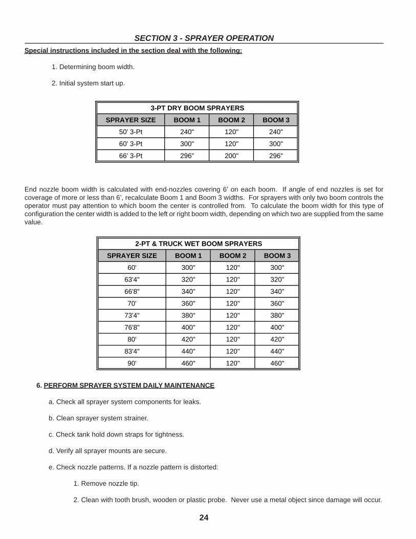
Special instructions included in the section deal with the following:
1. Determining boom width.
2. Initial system start up.
End nozzle boom width is calculated with end-nozzles covering 6’ on each boom. If angle of end nozzles is set forcoverage of more or less than 6’, recalculate Boom 1 and Boom 3 widths. For sprayers with only two boom controls theoperator must pay attention to which boom the center is controlled from. To calculate the boom width for this type ofconfiguration the center width is added to the left or right boom width, depending on which two are supplied from the samevalue.
6. PERFORM SPRAYER SYSTEM DAILY MAINTENANCE
a. Check all sprayer system components for leaks.
b. Clean sprayer system strainer.
c. Check tank hold down straps for tightness.
d. Verify all sprayer mounts are secure.
e. Check nozzle patterns. If a nozzle pattern is distorted:
1. Remove nozzle tip.
2. Clean with tooth brush, wooden or plastic probe. Never use a metal object since damage will occur.
SPRAYER SIZE BOOM 1 BOOM 2 BOOM 3
60' 300" 120" 300"
63'4" 320" 120" 320"
66'8" 340" 120" 340"
70' 360" 120" 360"
73'4" 380" 120" 380"
76'8" 400" 120" 400"
80' 420" 120" 420"
83'4" 440" 120" 440"
90' 460" 120" 460"
2-PT & TRUCK WET BOOM SPRAYERS
SPRAYER SIZE BOOM 1 BOOM 2 BOOM 3
50' 3-Pt 240" 120" 240"
60' 3-Pt 300" 120" 300"
66' 3-Pt 296" 200" 296"
3-PT DRY BOOM SPRAYERS
25
SECTION 3 - SPRAYER OPERATION
4. Replace nozzle tip if necessary.
5. Install nozzle tip back onto sprayer.
f. During periods of use in freezing temperatures:
1. (Flush entire sprayer system with 100% RV antifreeze.) RV antifreeze is nontoxic and safe for the environ-ment. It must be used in 100 percent concentrations, but it is more economical then permanent antifreezeto purchase and will not harm plastic spray components. Read and follow antifreeze container instructions.
2. Spray solution through nozzles.
3. Allow dripless nozzles to drain by loosening each diaphragm check valve nut.
g. When changing chemicals, follow chemical manufacturers’ WARNINGS, instructions and procedures concern-ing sprayer system cleaning.
3.5 MECHANICAL FIELD OPERATION AND ADJUSTMENT
1. OPEN TO FIELD POSITION
a. Remove transport clevis pins.
b. Unfold booms to field position one side at a time. On windshield sprayers, the pin that prevents the part onefrom folding up is easiest to install if it is done after the booms have been released from the transport rest andbefore the part two is unfolded.
c. Pin outside boom to inside boom on non cable suspended booms only.
d. Unlock swinging center beam to allow free movement from side to side.
IMPORTANT!LIQUID REMAINS IN THE 1 INCH WET BOOM EVEN WITH THE NOZZLE DIAPHRAGM CHECK VALVES LOOS-ENED. WITH BOTH BOOMS IN TRANSPORT POSITION LIQUID ACCUMULATES NEAR THE BOOM PIVOT POINT.TO ALLOW DRAINAGE, REMOVE THE BOOM END CAP OR END NOZZLE AND SUPPLY HOSE FROM EACHBOOM.
IMPORTANT!WHEN FOLDING AND DURING TRANSPORT THE CENTER BEAM SWING LOCKS MUST BE LOCKED TO PRE-VENT THE CENTER BEAM FROM MOVING. WHEN SPRAYING, THE CENTER BEAM MUST BE UNLOCKED TOALLOW PROPER FLOATING BOOM OPERATION.
26
SECTION 3 - SPRAYER OPERATION
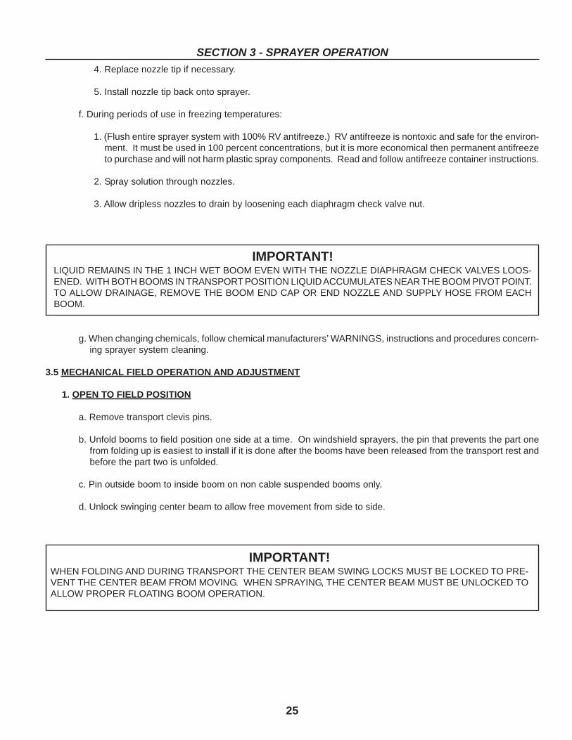
2. SETTING BOOM LEAD ON CABLE SUSPENDED BOOMS
Boom lead is the distance the outer end of the boom leads the inner end of boom. Adjustment from the factory setting of1 to 3 feet is accomplished by loosening the clamp at outer ends of the spring loaded cable and moving the boom to thepreferred position and tightening the cable clamp. The outer boom can be set to lead the inner boom by adjusting the gapdistance at the middle hinge. Gap distance is adjusted by loosening the 5/8” jam nuts and turning the 5/8” bolts inward oroutward. If the gap between the booms is too small the boom will be less likely to break away at the middle hinge pointwhen the boom collides with a fixed object.
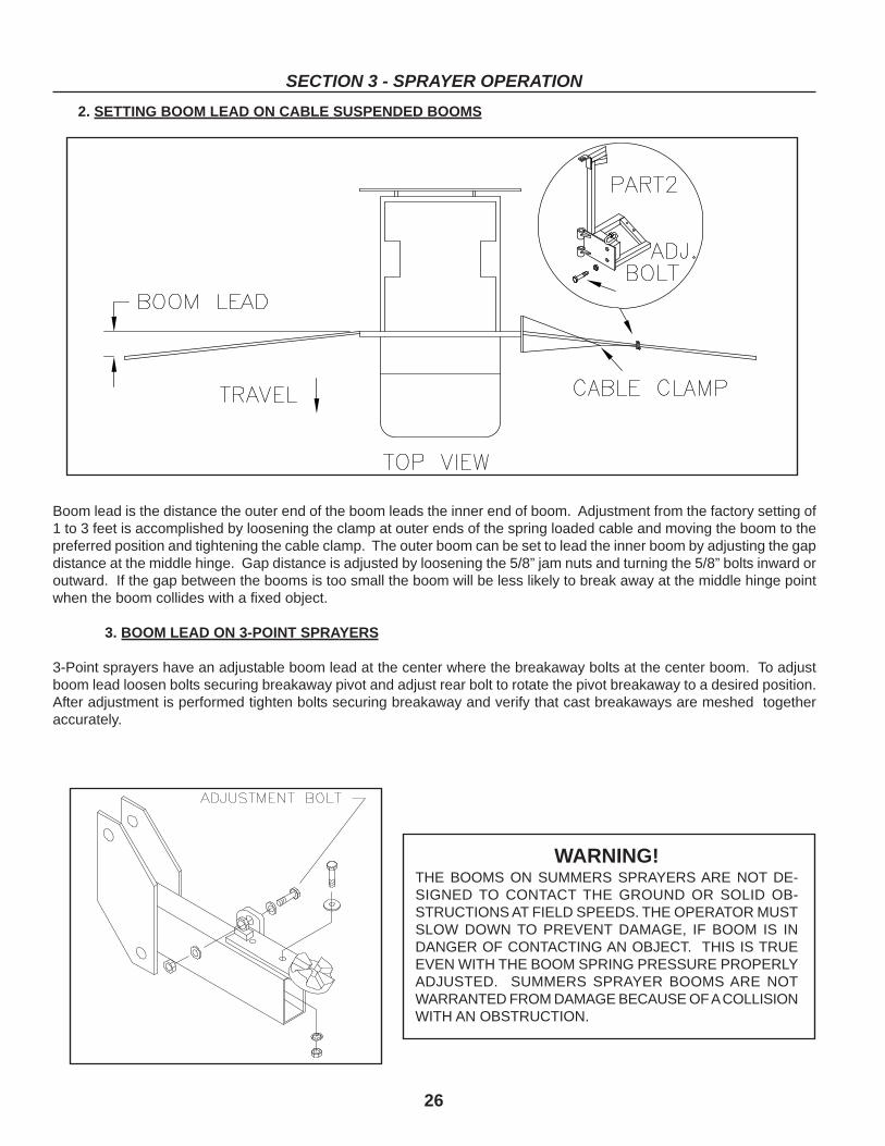
3. BOOM LEAD ON 3-POINT SPRAYERS
3-Point sprayers have an adjustable boom lead at the center where the breakaway bolts at the center boom. To adjustboom lead loosen bolts securing breakaway pivot and adjust rear bolt to rotate the pivot breakaway to a desired position.After adjustment is performed tighten bolts securing breakaway and verify that cast breakaways are meshed togetheraccurately.
WARNING!THE BOOMS ON SUMMERS SPRAYERS ARE NOT DE-SIGNED TO CONTACT THE GROUND OR SOLID OB-STRUCTIONS AT FIELD SPEEDS. THE OPERATOR MUSTSLOW DOWN TO PREVENT DAMAGE, IF BOOM IS INDANGER OF CONTACTING AN OBJECT. THIS IS TRUEEVEN WITH THE BOOM SPRING PRESSURE PROPERLYADJUSTED. SUMMERS SPRAYER BOOMS ARE NOTWARRANTED FROM DAMAGE BECAUSE OF A COLLISIONWITH AN OBSTRUCTION.
27
SECTION 3 - SPRAYER OPERATION
4. LEVELING BOOMS
Booms on the Summers cable suspended boom skid sprayer are factory set to be level but may need to be periodicallyleveled due to cable stretch. For minor adjustments of 2 or 3 inches the booms are leveled by adjusting the locking nut onthe eye bolts that control spring tension. The adjusting nuts are on top of the boom pivot arms. Major adjustments are asfollows:
a. Loosen nuts on eye bolts to approximately 1/2” from end of eye bolt.b. Remove tension from cables by supporting booms with jack stands or some other means.c. Detach chain from quick link and shorten by one link, reconnect chain to quick link and remove support
from booms.d. Finish leveling inner boom by adjusting the lock nuts on the eye bolt.e. If the inner boom is still not level, repeat steps 3 and 4.f. To level outer boom, adjust turnbuckle on single cable to raise or lower end of the outer boom.
5. BOOM BREAKAWAY
The adjustment of the boom breakaway spring is important. The spring controls the pressure between the two ductilecast breakaway clutches. Since the clutch parts are made of ductile cast, a certain amount of break-in wear is normalduring the first few hours of operation. The factory adjustment MUST BE CHECKED AFTER THE FIRST HOUR OF USE.The spring pressure is properly adjusted when the boom can be “broken away” with moderate force applied to the end ofthe boom. If the boom spring pressure is set too loose, the booms may break away during acceleration or at increasedspraying speeds. If the boom spring pressure is set too tight, the booms may not break away when colliding with anobstruction.Two point Sprayers and those equipped with windshields have a stabilizer latch attached to each part 1 boom.
The stabilizer assists the break away in keeping the boom in field position. The eye bolt must be adjusted to preload thestabilizer spring. This is accomplished as follows:
a. Unfold booms from transport position to a configuration where they are still folded in the middle.b. The pin for the stabilizer latch should just slide into the hole with 1/16 to 1/8” to spare between the pin
and the eye bolt.c. If adjustment is necessary loosen the jamb nuts on the eye bolt and adjust the eye to take up most of
the slack on the pin. The pin should still be free to permit removal and insertion.d. Unfold booms completely and verify pin is tight and spring is preloaded. Pin should not be able to be
removed when boom is in spray position. If pin is loose eyebolt breakage may occur more often.
6. PART 2 LATCH
Part 2 latches are preset at the factory to a spring installed height of 1-15/16”. Field adjustment of latches may benecessary to provide enough pressure to suit operator needs. Excessive tightening will increase damages if the boomstrikes a secure object. After adjustment the operator should force part 2 booms to break away insuring that the springhas room to collapse and boom will break away.
7. PIVOT ARM STOP BOLT ADJUSTMENT
Pivot stops are adjusted at the factory, but adjustment may be required due to wear in. Pivot and cylinder stops must beadjusted at the same time. Adjustment is performed as follows:
1. Place sprayer on a level surface and verify the pivot arms are vertical.2. Activate tip lift slightly to remove pressure on stop bolts.3. Adjust bolts to desired position.4. Retract cylinder to verify that it contacts the stop at the same instant cylinder closes.5. Cylinder is adjusted by loosening the clevis pinch bolt and turning the clevis to the desired setting.6. Tighten clevis pinch bolt after reaching desired setting.
CAUTION!THE BREAKAWAY IS UNDER HIGH SPRING TENSION.
28
SECTION 3 - SPRAYER OPERATION
3.6 SPRAYER SYSTEM FIELD OPERATION
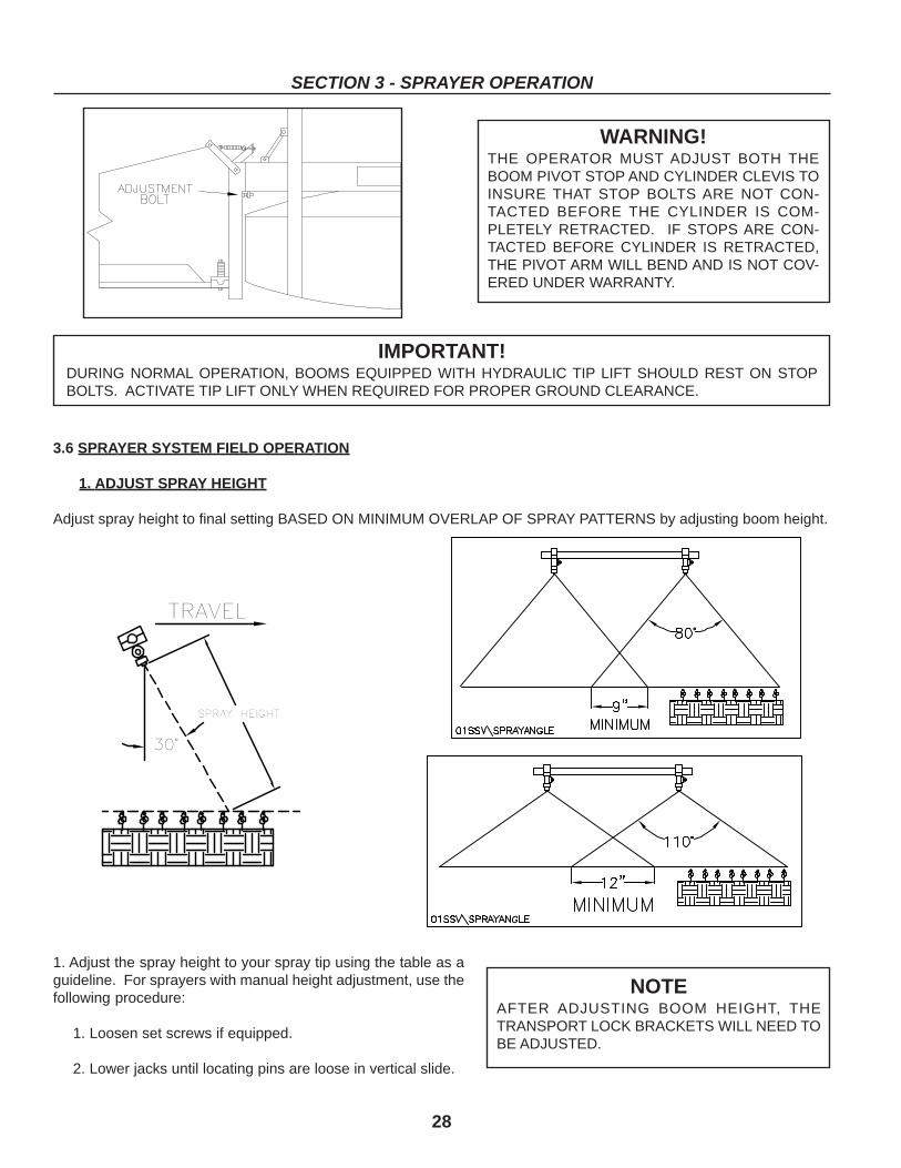
1. ADJUST SPRAY HEIGHT
Adjust spray height to final setting BASED ON MINIMUM OVERLAP OF SPRAY PATTERNS by adjusting boom height.
WARNING!THE OPERATOR MUST ADJUST BOTH THEBOOM PIVOT STOP AND CYLINDER CLEVIS TOINSURE THAT STOP BOLTS ARE NOT CON-TACTED BEFORE THE CYLINDER IS COM-PLETELY RETRACTED. IF STOPS ARE CON-TACTED BEFORE CYLINDER IS RETRACTED,THE PIVOT ARM WILL BEND AND IS NOT COV-ERED UNDER WARRANTY.
IMPORTANT!DURING NORMAL OPERATION, BOOMS EQUIPPED WITH HYDRAULIC TIP LIFT SHOULD REST ON STOPBOLTS. ACTIVATE TIP LIFT ONLY WHEN REQUIRED FOR PROPER GROUND CLEARANCE.
1. Adjust the spray height to your spray tip using the table as aguideline. For sprayers with manual height adjustment, use thefollowing procedure:
1. Loosen set screws if equipped.
2. Lower jacks until locating pins are loose in vertical slide.
NOTEAFTER ADJUSTING BOOM HEIGHT, THETRANSPORT LOCK BRACKETS WILL NEED TOBE ADJUSTED.
29
SECTION 3 - SPRAYER OPERATION
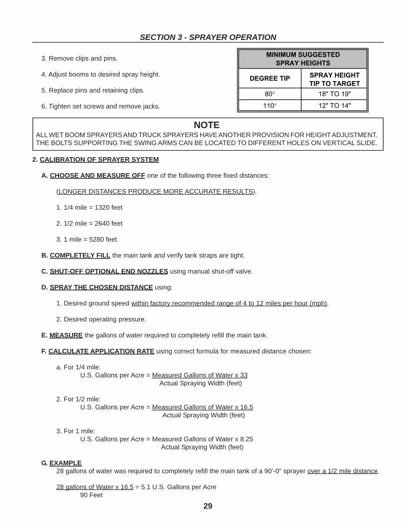
3. Remove clips and pins.
4. Adjust booms to desired spray height.
5. Replace pins and retaining clips.
6. Tighten set screws and remove jacks.
2. CALIBRATION OF SPRAYER SYSTEM
A. CHOOSE AND MEASURE OFF one of the following three fixed distances:
(LONGER DISTANCES PRODUCE MORE ACCURATE RESULTS).
1. 1/4 mile = 1320 feet
2. 1/2 mile = 2640 feet
3. 1 mile = 5280 feet
B. COMPLETELY FILL the main tank and verify tank straps are tight.
C. SHUT-OFF OPTIONAL END NOZZLES using manual shut-off valve.
D. SPRAY THE CHOSEN DISTANCE using:
1. Desired ground speed within factory recommended range of 4 to 12 miles per hour (mph).
2. Desired operating pressure.
E. MEASURE the gallons of water required to completely refill the main tank.
F. CALCULATE APPLICATION RATE using correct formula for measured distance chosen:
a. For 1/4 mile:U.S. Gallons per Acre = Measured Gallons of Water x 33
Actual Spraying Width (feet)
2. For 1/2 mile:U.S. Gallons per Acre = Measured Gallons of Water x 16.5
Actual Spraying Width (feet)
3. For 1 mile:U.S. Gallons per Acre = Measured Gallons of Water x 8.25
Actual Spraying Width (feet)
G. EXAMPLE28 gallons of water was required to completely refill the main tank of a 90’-0” sprayer over a 1/2 mile distance.
28 gallons of Water x 16.5 = 5.1 U.S. Gallons per Acre 90 Feet
NOTEALL WET BOOM SPRAYERS AND TRUCK SPRAYERS HAVE ANOTHER PROVISION FOR HEIGHT ADJUSTMENT.THE BOLTS SUPPORTING THE SWING ARMS CAN BE LOCATED TO DIFFERENT HOLES ON VERTICAL SLIDE.
���������� ���(�'���'�
�������������
�� ��3�����3
��� ��3�����3
����� ���� ���
���(�'���'�
30
SECTION 3 - SPRAYER OPERATION
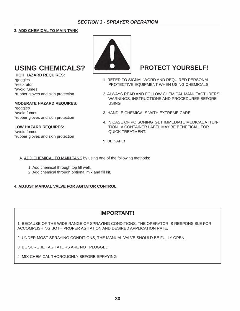
USING CHEMICALS?HIGH HAZARD REQUIRES:*goggles*respirator*avoid fumes*rubber gloves and skin protection
MODERATE HAZARD REQUIRES:*goggles*avoid fumes*rubber gloves and skin protection
LOW HAZARD REQUIRES:*avoid fumes*rubber gloves and skin protection
PROTECT YOURSELF!
1. REFER TO SIGNAL WORD AND REQUIRED PERSONALPROTECTIVE EQUIPMENT WHEN USING CHEMICALS.
2. ALWAYS READ AND FOLLOW CHEMICAL MANUFACTURERS’WARNINGS, INSTRUCTIONS AND PROCEDURES BEFOREUSING.
3. HANDLE CHEMICALS WITH EXTREME CARE.
4. IN CASE OF POISONING, GET IMMEDIATE MEDICAL ATTEN-TION. A CONTAINER LABEL MAY BE BENEFICIAL FORQUICK TREATMENT.
5. BE SAFE!
3. ADD CHEMICAL TO MAIN TANK
A. ADD CHEMICAL TO MAIN TANK by using one of the following methods:
1. Add chemical through top fill well.2. Add chemical through optional mix and fill kit.
4. ADJUST MANUAL VALVE FOR AGITATOR CONTROL
IMPORTANT!
1. BECAUSE OF THE WIDE RANGE OF SPRAYING CONDITIONS, THE OPERATOR IS RESPONSIBLE FORACCOMPLISHING BOTH PROPER AGITATION AND DESIRED APPLICATION RATE.
2. UNDER MOST SPRAYING CONDITIONS, THE MANUAL VALVE SHOULD BE FULLY OPEN.
3. BE SURE JET AGITATORS ARE NOT PLUGGED.
4. MIX CHEMICAL THOROUGHLY BEFORE SPRAYING.
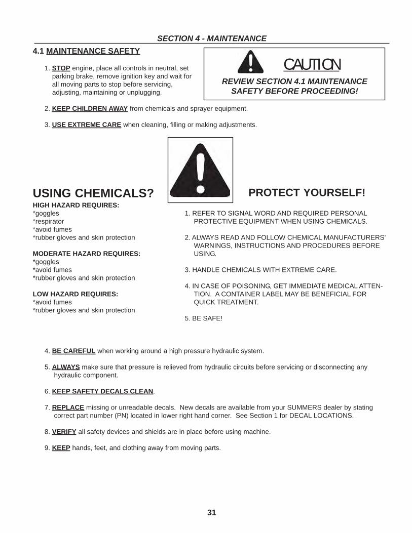
31
SECTION 4 - MAINTENANCE
4.1 MAINTENANCE SAFETY
1. STOP engine, place all controls in neutral, set parking brake, remove ignition key and wait for all moving parts to stop before servicing, adjusting, maintaining or unplugging.
2. KEEP CHILDREN AWAY from chemicals and sprayer equipment.
3. USE EXTREME CARE when cleaning, filling or making adjustments.
4. BE CAREFUL when working around a high pressure hydraulic system.
5. ALWAYS make sure that pressure is relieved from hydraulic circuits before servicing or disconnecting anyhydraulic component.
6. KEEP SAFETY DECALS CLEAN.
7. REPLACE missing or unreadable decals. New decals are available from your SUMMERS dealer by statingcorrect part number (PN) located in lower right hand corner. See Section 1 for DECAL LOCATIONS.
8. VERIFY all safety devices and shields are in place before using machine.
9. KEEP hands, feet, and clothing away from moving parts.
CAUTIONREVIEW SECTION 4.1 MAINTENANCE
SAFETY BEFORE PROCEEDING!
USING CHEMICALS?HIGH HAZARD REQUIRES:*goggles*respirator*avoid fumes*rubber gloves and skin protection
MODERATE HAZARD REQUIRES:*goggles*avoid fumes*rubber gloves and skin protection
LOW HAZARD REQUIRES:*avoid fumes*rubber gloves and skin protection
PROTECT YOURSELF!
1. REFER TO SIGNAL WORD AND REQUIRED PERSONALPROTECTIVE EQUIPMENT WHEN USING CHEMICALS.
2. ALWAYS READ AND FOLLOW CHEMICAL MANUFACTURERS’WARNINGS, INSTRUCTIONS AND PROCEDURES BEFOREUSING.
3. HANDLE CHEMICALS WITH EXTREME CARE.
4. IN CASE OF POISONING, GET IMMEDIATE MEDICAL ATTEN-TION. A CONTAINER LABEL MAY BE BENEFICIAL FORQUICK TREATMENT.
5. BE SAFE!
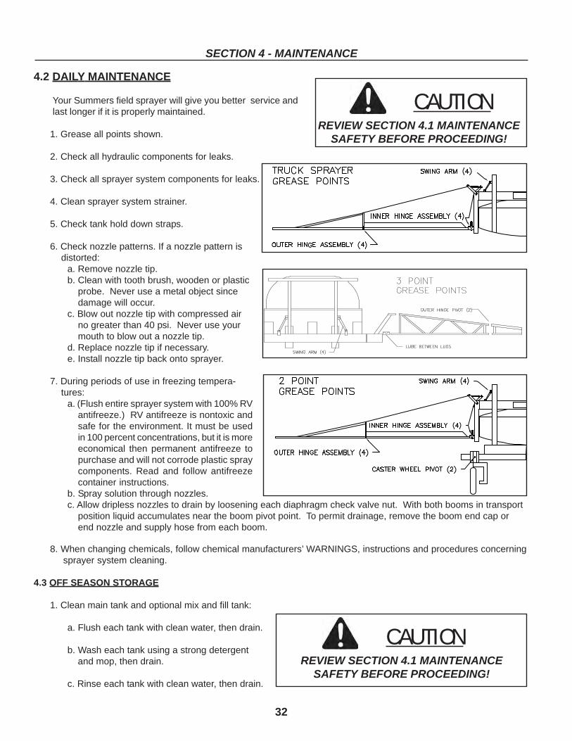
32
SECTION 4 - MAINTENANCE
8. When changing chemicals, follow chemical manufacturers’ WARNINGS, instructions and procedures concerningsprayer system cleaning.
4.3 OFF SEASON STORAGE
1. Clean main tank and optional mix and fill tank:
a. Flush each tank with clean water, then drain.
b. Wash each tank using a strong detergent and mop, then drain.
c. Rinse each tank with clean water, then drain.
CAUTIONREVIEW SECTION 4.1 MAINTENANCE
SAFETY BEFORE PROCEEDING!
4.2 DAILY MAINTENANCE
Your Summers field sprayer will give you better service andlast longer if it is properly maintained.
1. Grease all points shown.
2. Check all hydraulic components for leaks.
3. Check all sprayer system components for leaks.
4. Clean sprayer system strainer.
5. Check tank hold down straps.
6. Check nozzle patterns. If a nozzle pattern isdistorted:
a. Remove nozzle tip.b. Clean with tooth brush, wooden or plastic
probe. Never use a metal object sincedamage will occur.
c. Blow out nozzle tip with compressed airno greater than 40 psi. Never use yourmouth to blow out a nozzle tip.
d. Replace nozzle tip if necessary.e. Install nozzle tip back onto sprayer.
7. During periods of use in freezing tempera-tures:
a. (Flush entire sprayer system with 100% RVantifreeze.) RV antifreeze is nontoxic andsafe for the environment. It must be usedin 100 percent concentrations, but it is moreeconomical then permanent antifreeze topurchase and will not corrode plastic spraycomponents. Read and follow antifreezecontainer instructions.
b. Spray solution through nozzles.c. Allow dripless nozzles to drain by loosening each diaphragm check valve nut. With both booms in transport
position liquid accumulates near the boom pivot point. To permit drainage, remove the boom end cap orend nozzle and supply hose from each boom.
CAUTIONREVIEW SECTION 4.1 MAINTENANCE
SAFETY BEFORE PROCEEDING!
33
SECTION 4 - MAINTENANCE
2. Clean entire sprayer system:
a. Partially fill each tank with clean water and add one part household ammonia for every 100 parts water.
b. Start pump and circulate solution through entire sprayer system. Spray solution through nozzles, then drain.
3. Winterize entire sprayer system:
a. (Flush entire sprayer system with 100% RV antifreeze.) RV antifreeze is nontoxic and safe for the environ-ment. It must be used in 100 percent concentrations, but it is more economical then permanent antifreezeto purchase and will not harm plastic spray components. Read and follow antifreeze container instructions.
b. Spray solution through nozzles.
c. Allow dripless nozzles to drain by loosening each diaphragm check valve nut.
IMPORTANT!Some liquid remains in the 1 inch wet boom even with the nozzle diaphragm check valves loosened. With both boomsin transport position liquid accumulates near the boom pivot point. To allow drainage, remove the boom end cap orend nozzle and supply hose from each boom.
4.4 PRESEASON ANNUAL MAINTENANCE
1. READ AND UNDERSTAND Operator’s Manual before using machine.
2. Check tire pressure.
3. Inspect sprayer components.
4. Inspect hydraulic components.
5. Grease wheel bearings and inspect for looseness.
6. Check tank(s) for cracks and verify straps are tight.
7. Tighten each diaphragm check valve nut on dripless nozzles.
8. Refer to SECTION 3 - SPRAYER OPERATION for setup and start-up procedures.
9. Flush winterizing antifreeze solution from entire sprayer system with clean water. Spray rinse water throughnozzles. (If automotive antifreeze was used, it is a hazardous material and must be disposed of properly.)
IMPORTANT!WHEN NOT IN USE TANK SHOULD BE STORED IN A DRY DARK PLACE. ALTHOUGH ULTRA VIOLET STABILIZ-ERS ARE ADDED TO PROTECT THE TANKS FROM SUNLIGHT DAMAGE, ALL POLYOLEFIN MATERIALS WILLDETERIORATE IN TIME. TANK MANUFACTURERS RECOMMEND STORAGE OUT OF SUNLIGHT TO LENGTHENTHE LIFE OF ALL PLASTIC TANKS. DO NOT DROP, STRIKE, OR KICK TANK AT LOW TEMPERATURES. ALLPOLY MATERIALS ARE INCREASINGLY SUBJECT TO CRACKING AS THE TEMPERATURES FALL BELOW 20°F.
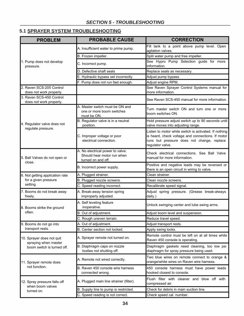
������� ��������� � ����������
���������� ��� ��� ��������������� ��� � � ��� ����� ���� ������ ����
�� � ����������
������������������ ��� ��� ������������������������
����������� ��������� !��� "��� ����� �� ���� �� ����
����� ���
#��#��� ����$� ������ %������������������������!�
&�� !��������!������� �������� �!� ��'�� �������!�����
���"����������� ������� ������$� ��'�� �������%"(�
)��%��������*)+,���� ���
����������� �������������!�
��� %���� ����!�� ��� ��� �!� ��� ������ ��
���������� ���
-��%��������*.,+���� ���
����������� �������������!�����%��������*.,+��������������������� ���
���(�� ����� �$���� �����/�����
����������������������� �$��
������� �����/�
0��� ��� �� �� �$ �/ ��� ��� ��� �� ����
������� �$����/�
���%����� ������������������ ���
�������� ���
��� �������� ��'�� �� �$ �� � 1+ ������� �� �
������������� ����'�� ���������
��������������� �����������
��������� ����������� ���
2� �� � �� �� �$�� �� �$ � �� �� ��� � �� $��
� $����3 �$��� ��� ��� ��� ������ ���� � �� ��
���� �� �������� ���� �� �$����3 �������
������ ���������
���/������ ����������� ��������
�����$�����$������ ��������$��
���� ���������������
�$��� ���� ���� ������ ���� ��� ���� 4����
�������������������� ���
����������� ������������!�"�� �� ��� ���� �� ����� ��! �� �������� ��
$������������������ �������� ��������
���"�������� ������ ������� ������
���"���������������������� ���������������������
����������������������� � %������� ��������������
5������������� ����������!
��������!�
��������*���!� ������������
������������!���'�� ���
��'�� ����� ��������� 67����� �����*����!�
���!�8
����������������� ���
����������� ���9���������������� ����������������������
����� �����'�� ��� � ��'�� ��������������������������
���%���$�������� ������ %������ ������������
����� �����'�� ��� � ��'�� � ������� ���� ��
������ ������ ����� �������� ����!������������
�������!������� ���� � ���������%��� � ��� ��� ��� �� �� �� � ��� ��� �$��
%�����.,+���������������� ���
���#��$�������������������
������������� ��$� �����
#��$���� ����� � ���� �������3 �� ��� ��
���$������������!��������������������
���%��� ���� ������������ �!�0�� ���� ���� �� ���� � ������ � ������ :
������;�$ ����������%���������$�������
���%�����.,+�������������$������
���������� ���������
.,+ ������� $������ ��� $��� ����� �����
$������������ � ����������
���"���������������� ������6� ��8�����$ � �� � $ ������� ��� ���� � � $
��������������
��������!����� ������������ �� ��� �$���������������������� �������
�������������������� ������� � �$����������������������
<��"����������� ��������
�������������
.��%����� ����������������
���������� �����������
,�������4����������� ��������
����������
=��/� ��� ��������� ����� �
����������������������
������ ���
<+������!���������� �>�
����������!����$������ ��
������������� �$��� ��������
<<������!������� ������
�������� ���� ���
<)������!����������������
�������$��������������
������ ���������
?��������� ���� $��������
����� ���
1������������� ����� ��
���� ������� ���� ��
34
SECTION 5 - TROUBLESHOOTING
5.1 SPRAYER SYSTEM TROUBLESHOOTING
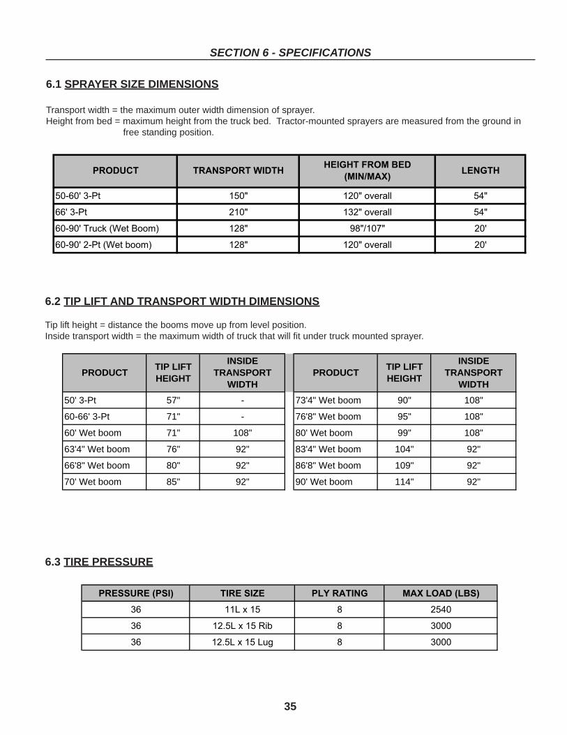
35
SECTION 6 - SPECIFICATIONS
6.1 SPRAYER SIZE DIMENSIONS
Transport width = the maximum outer width dimension of sprayer.Height from bed = maximum height from the truck bed. Tractor-mounted sprayers are measured from the ground in
free standing position.
6.2 TIP LIFT AND TRANSPORT WIDTH DIMENSIONS
Tip lift height = distance the booms move up from level position.Inside transport width = the maximum width of truck that will fit under truck mounted sprayer.
6.3 TIRE PRESSURE
������������ ������� � ������� ���� ����� ��
�� �������� ���
�� � ����������� ����
�� � ����������� ����
����������� ���� ����������� ���
�������� ��� ����������� ���
���������� !�"#���$��%& �� ��'��(� ��
�����������"#������%& �� ����������� ��
������� ����������������������������������
�������
50' 3-Pt 57" - 73'4" Wet boom 90" 108"
60-66' 3-Pt 71" - 76'8" Wet boom 95" 108"
60' Wet boom 71" 108" 80' Wet boom 99" 108"
63'4" Wet boom 76" 92" 83'4" Wet boom 104" 92"
66'8" Wet boom 80" 92" 86'8" Wet boom 109" 92"
70' Wet boom 85" 92" 90' Wet boom 114" 92"
TIP LIFT HEIGHT
INSIDE TRANSPORT
WIDTHPRODUCT PRODUCT
TIP LIFT HEIGHT
INSIDE TRANSPORT
WIDTH
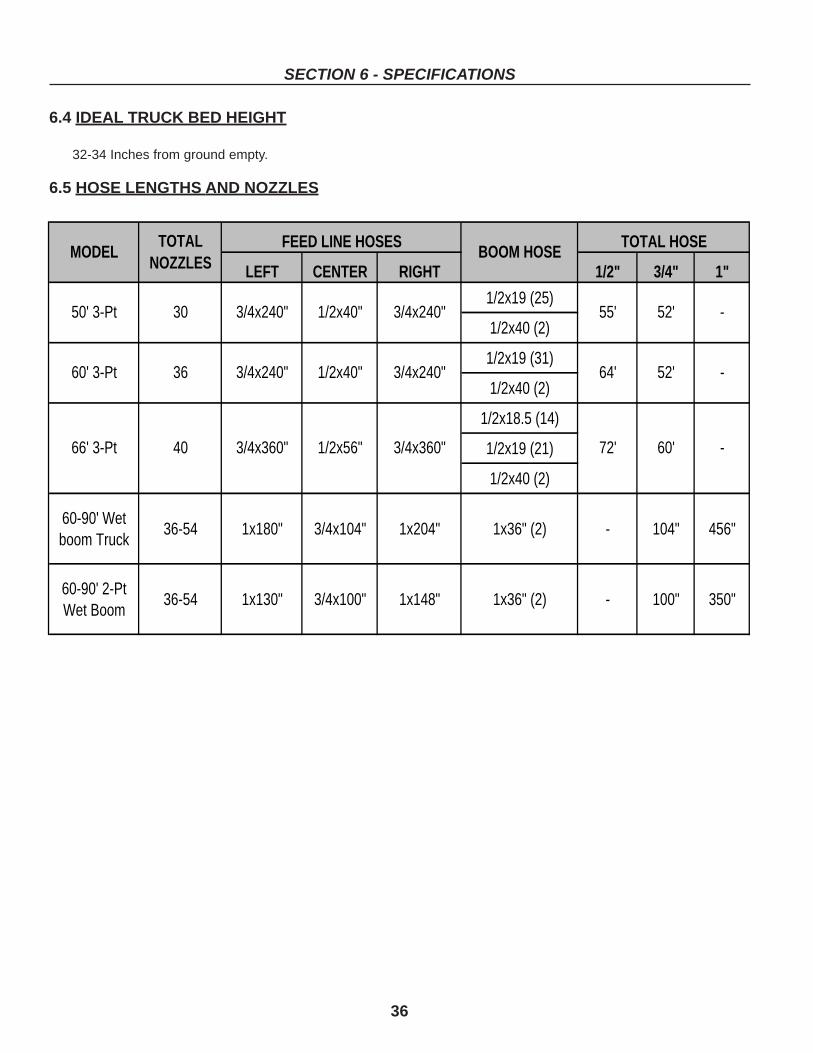
36
SECTION 6 - SPECIFICATIONS
6.4 IDEAL TRUCK BED HEIGHT
32-34 Inches from ground empty.
6.5 HOSE LENGTHS AND NOZZLES
LEFT CENTER RIGHT 1/2" 3/4" 1"
1/2x19 (25)
1/2x40 (2)
1/2x19 (31)
1/2x40 (2)
1/2x18.5 (14)
1/2x19 (21)
1/2x40 (2)
60-90' Wet boom Truck
36-54 1x180" 3/4x104" 1x204" 1x36" (2) - 104" 456"
60-90' 2-Pt Wet Boom
36-54 1x130" 3/4x100" 1x148" 1x36" (2) - 100" 350"
1/2x56"3/4x360"4066' 3-Pt
3/4x240" 64' 52'
60'72'3/4x360"
60' 3-Pt 36 3/4x240" 1/2x40"
MODELFEED LINE HOSES
BOOM HOSETOTAL HOSETOTAL
NOZZLES
50' 3-Pt 30 3/4x240" 1/2x40" 3/4x240" 55' 52' -
-
-
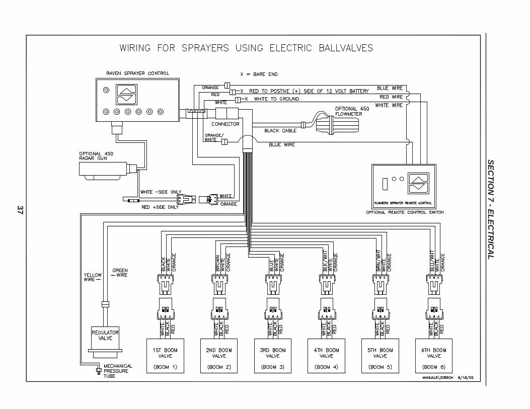
37
SE
CT
ION
7 - EL
EC
TR
ICA
L

38
SE
CT
ION
7 - EL
EC
TR
ICA
L
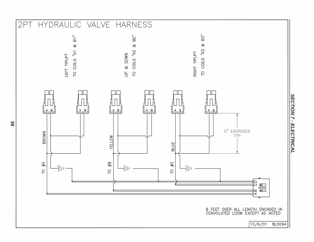
39
SE
CT
ION
7 - EL
EC
TR
ICA
L
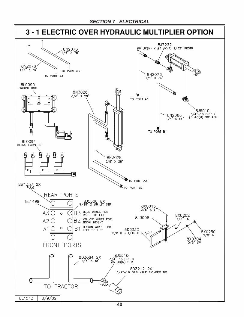
40
SECTION 7 - ELECTRICAL

SECTION 8 - PARTS
REMEMBER TO BRING OWNER REGISTER INFORMATIONLOCATED AT THE BEGINNING OF THIS MANUAL WHEN
ORDERING PARTS. SERIAL NUMBER INFORMATIONIS REQUIRED FOR ISSUE OF CORRECT PART.
41
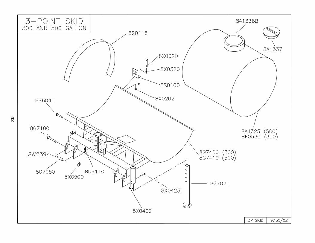
42
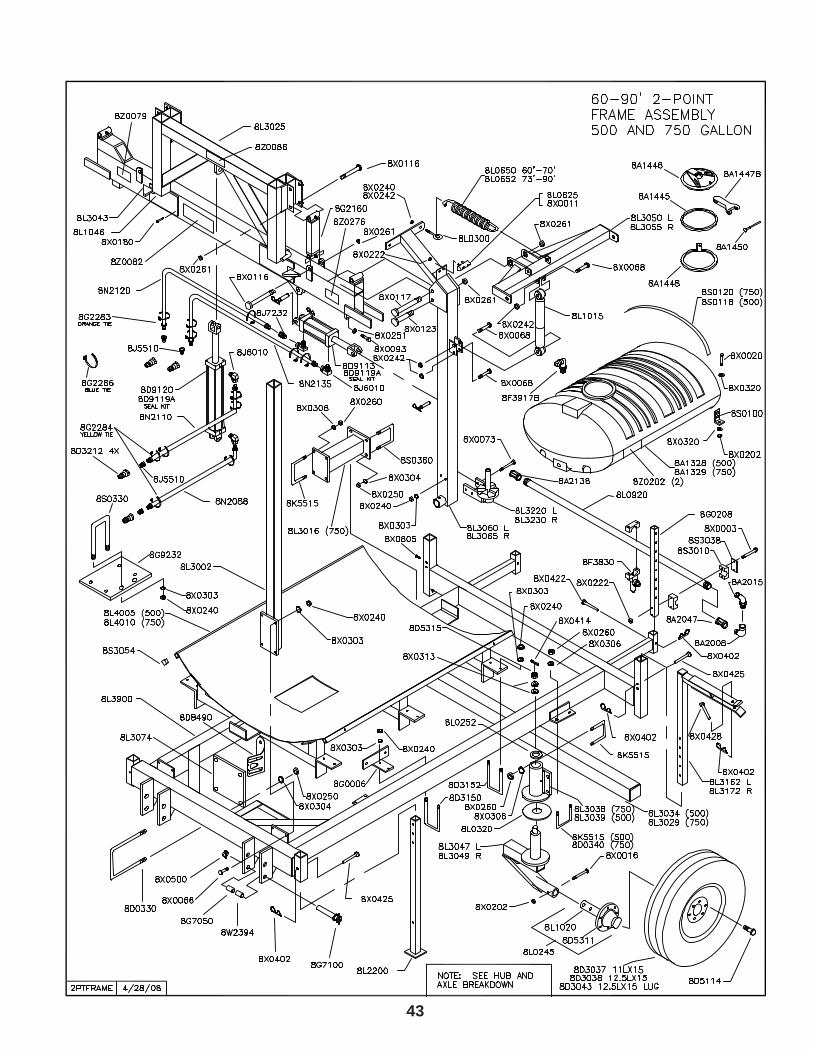
43
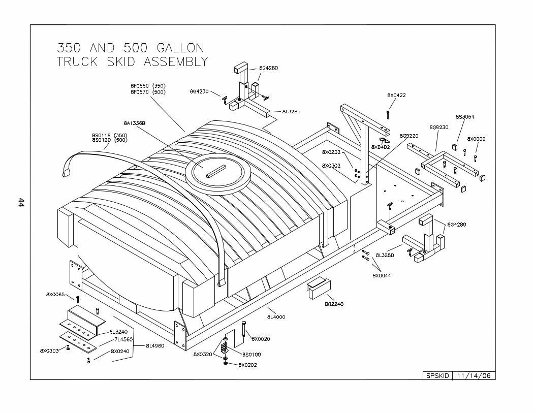
44
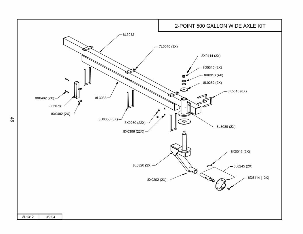
45
������ ����
��� ���������� ���������������
����������
���������
����������
������
�����������
�����������
������
������
����������
���������
������������
�����������
����������
������������
�����������
����������
����������
����������
������������
����������
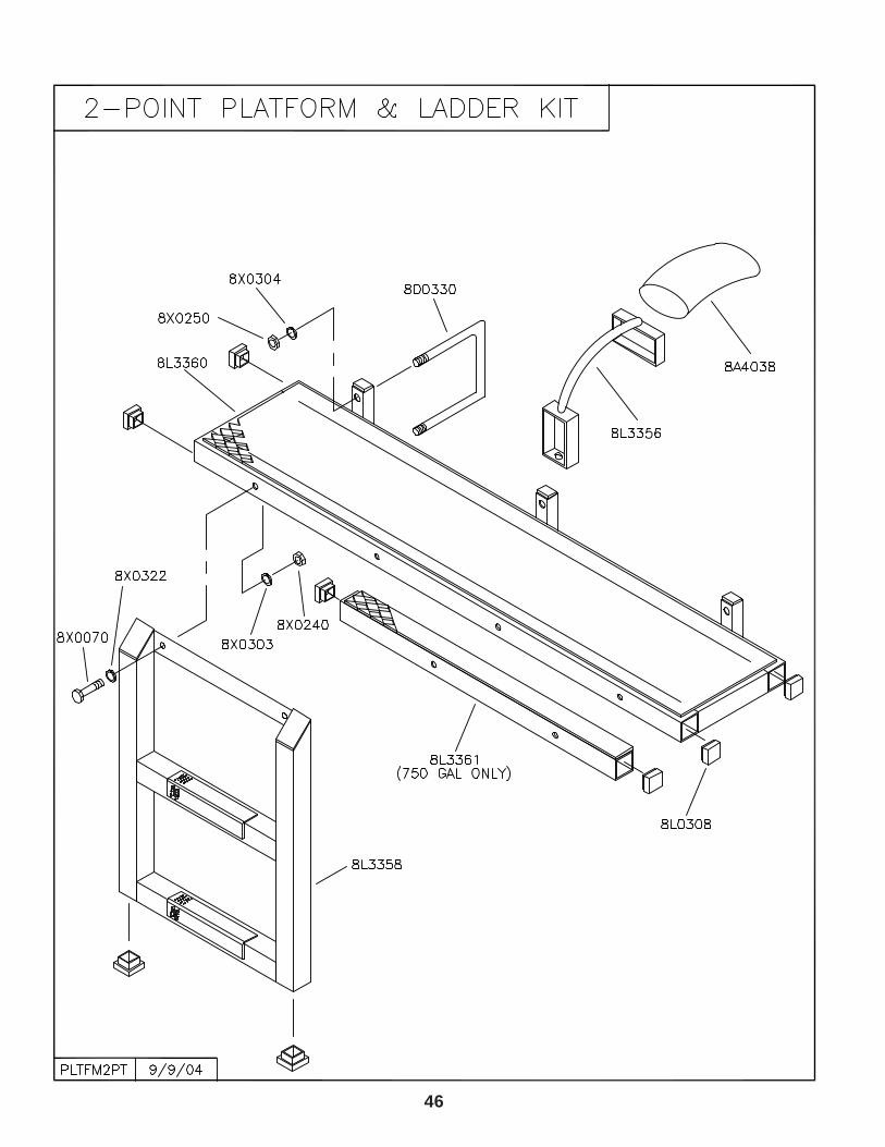
46
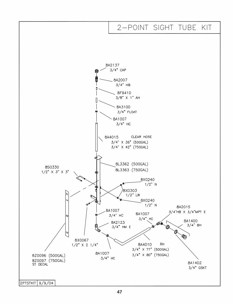
47
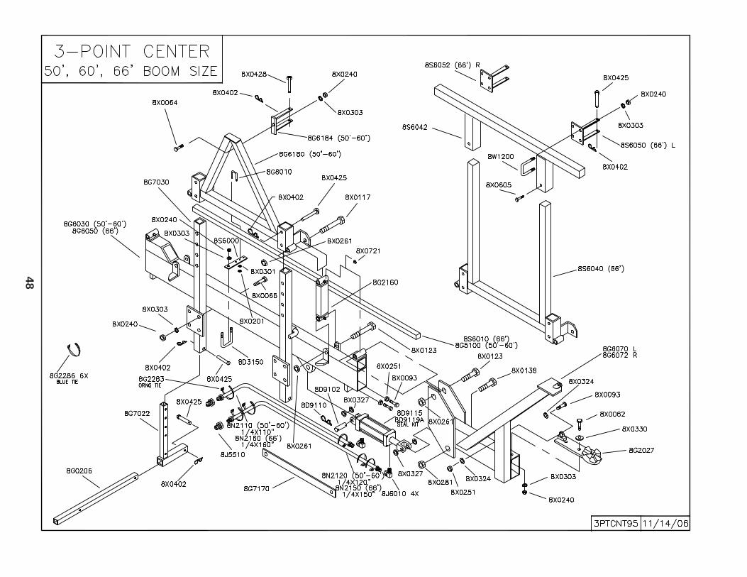
48
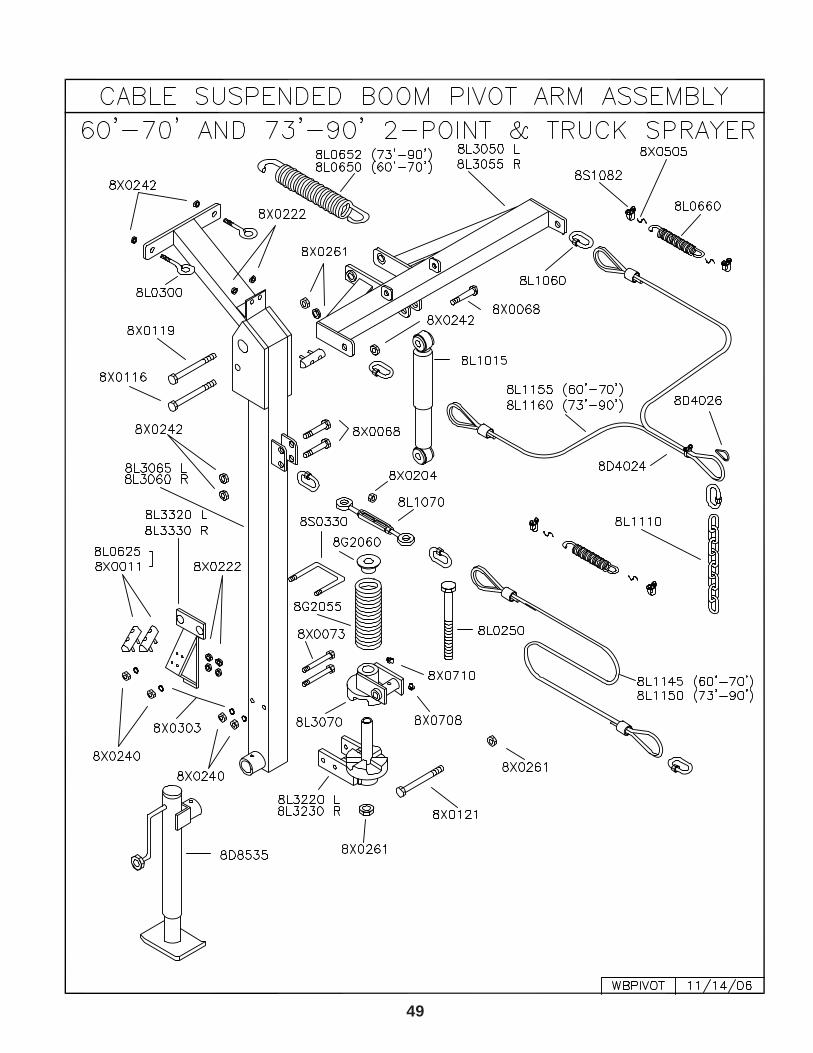
49
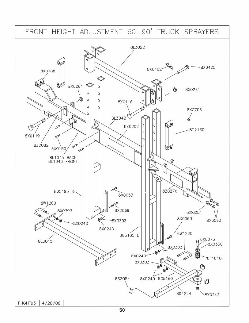
50
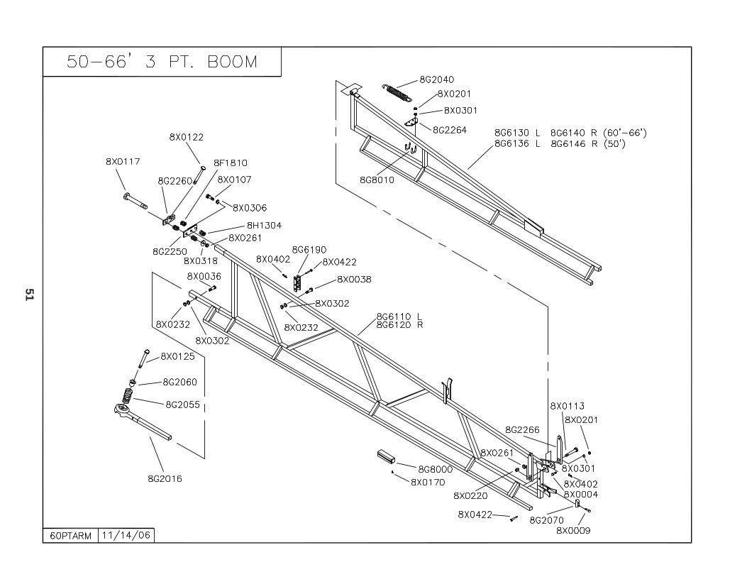
51
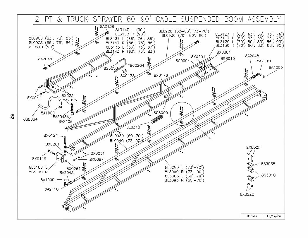
52
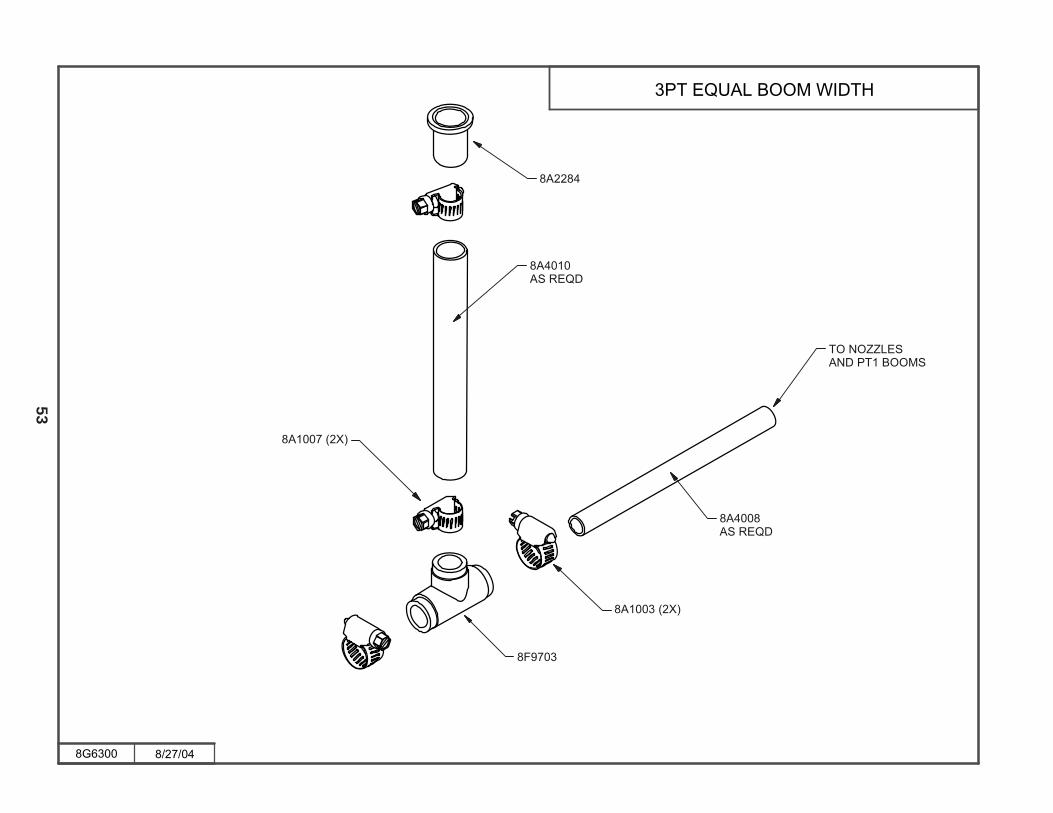
53
���� �����
���������� !�����"
������#�$���
����������
��%���
����������
������#�$���
�� �� &&��#��������� !#
������
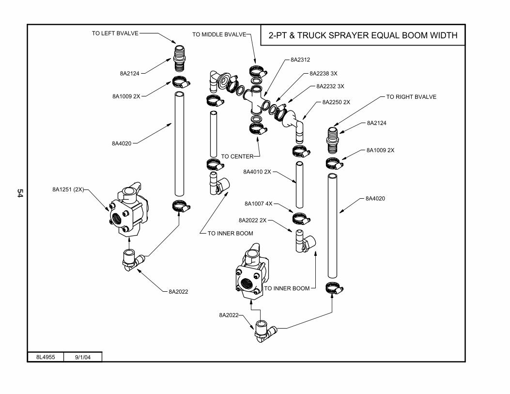
54
����� ����
�����'��$�(��#�$�)�$������� !�����"
������
�� �$��"�� *��*�
��������
����
������
���������
� �����$� !�
�������
�������
���������
����������
����������
�������
�� �!������ *��*�
�� �(����$
�� �����$� !
������
��������
����
������
�
�
� ���%�� *��*��
������������
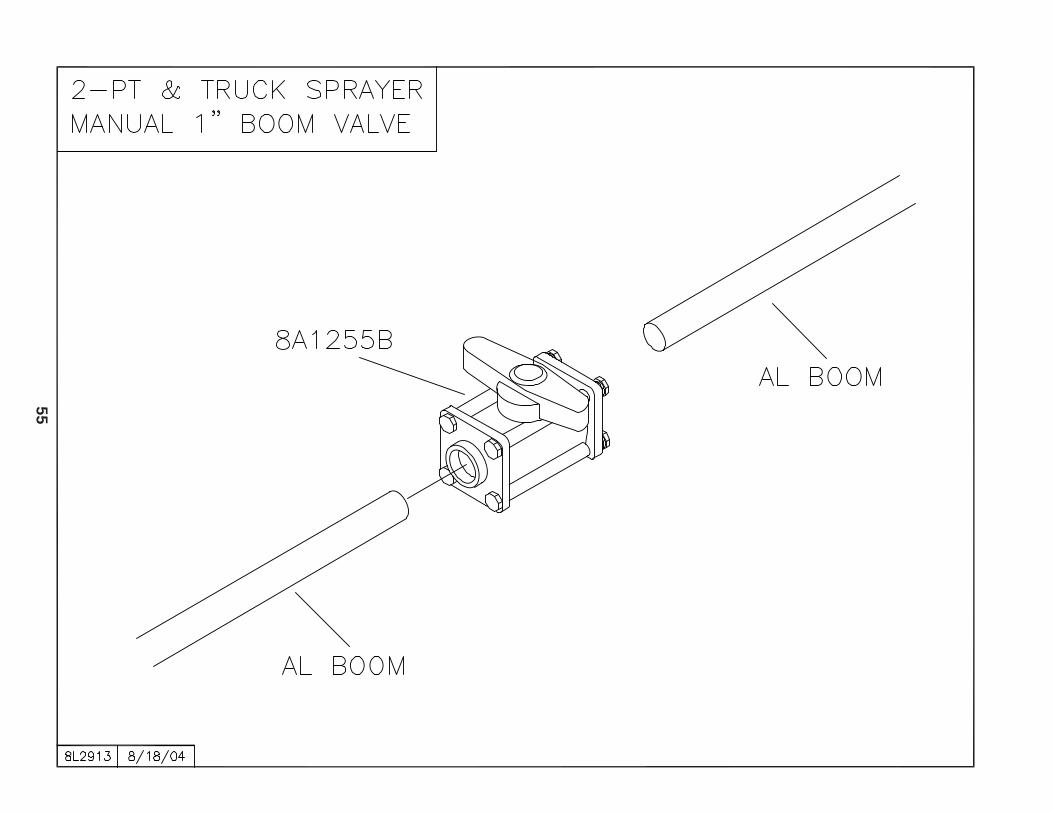
55
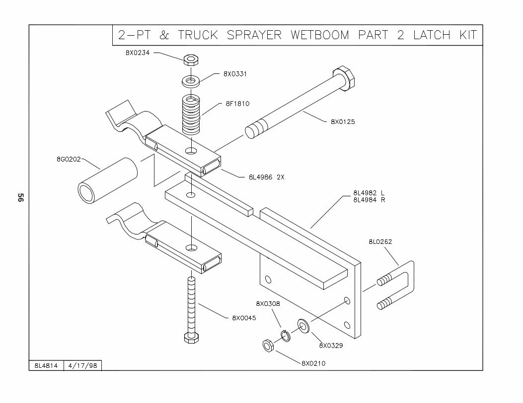
56

57
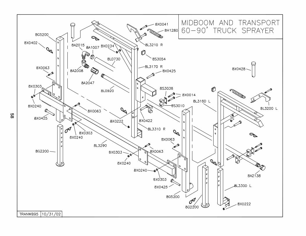
58

59
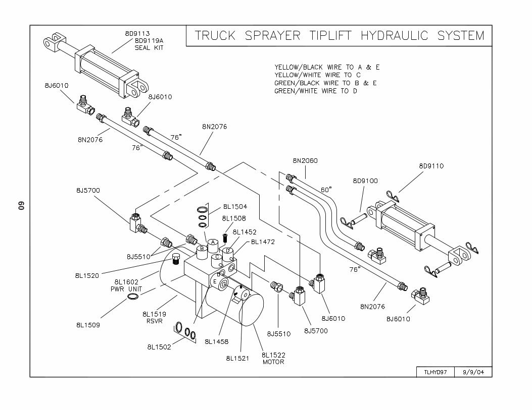
60
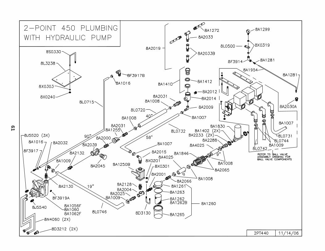
61
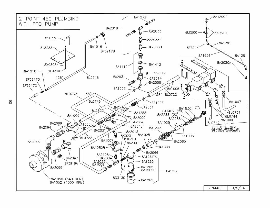
62
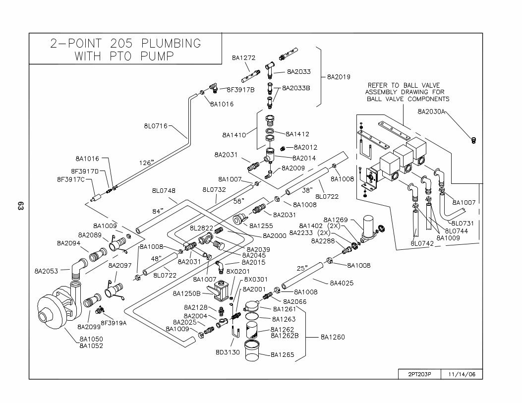
63
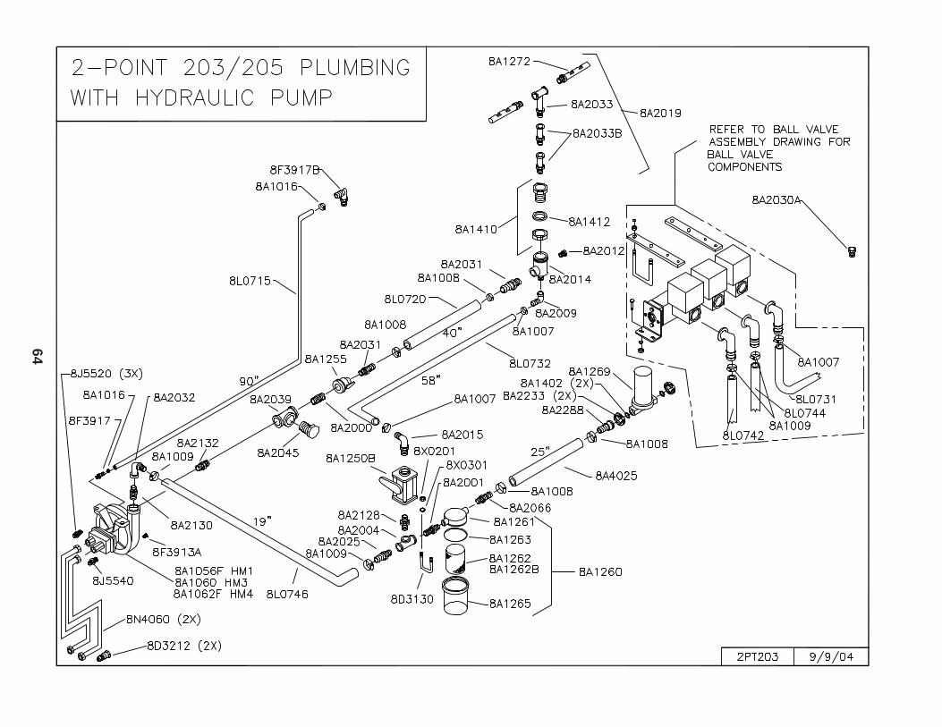
64
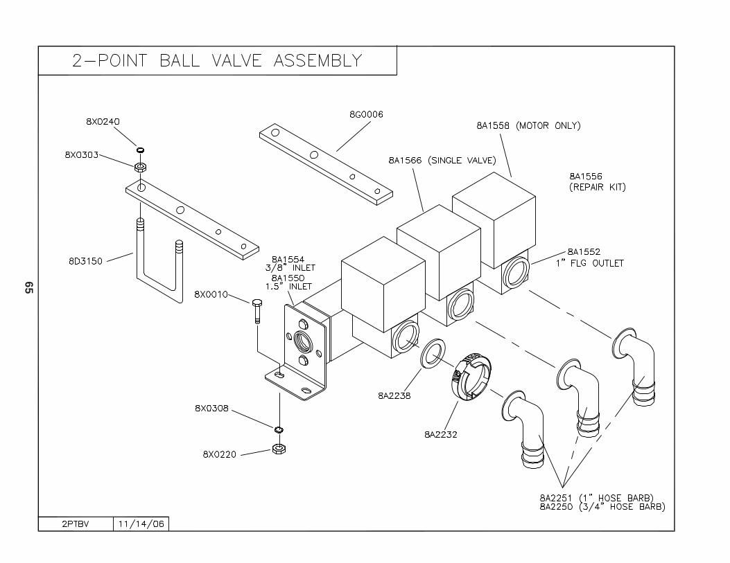
65
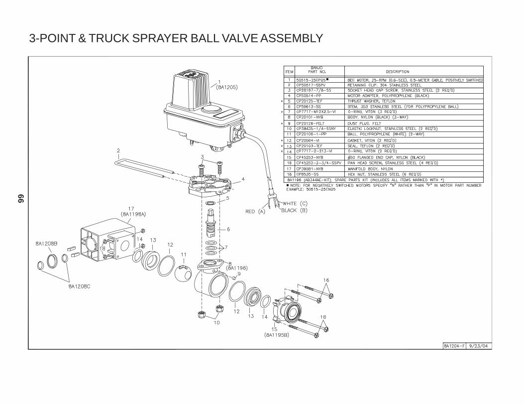
66
3-POINT & TRUCK SPRAYER BALL VALVE ASSEMBLY
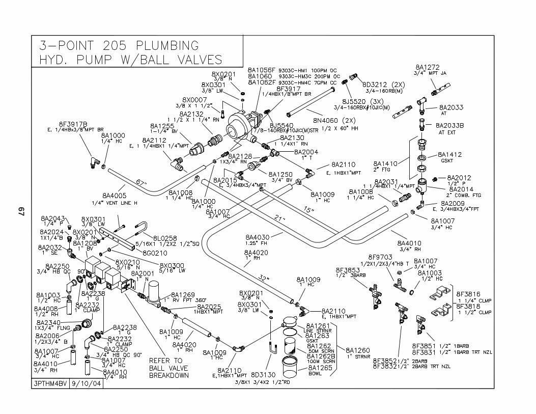
67
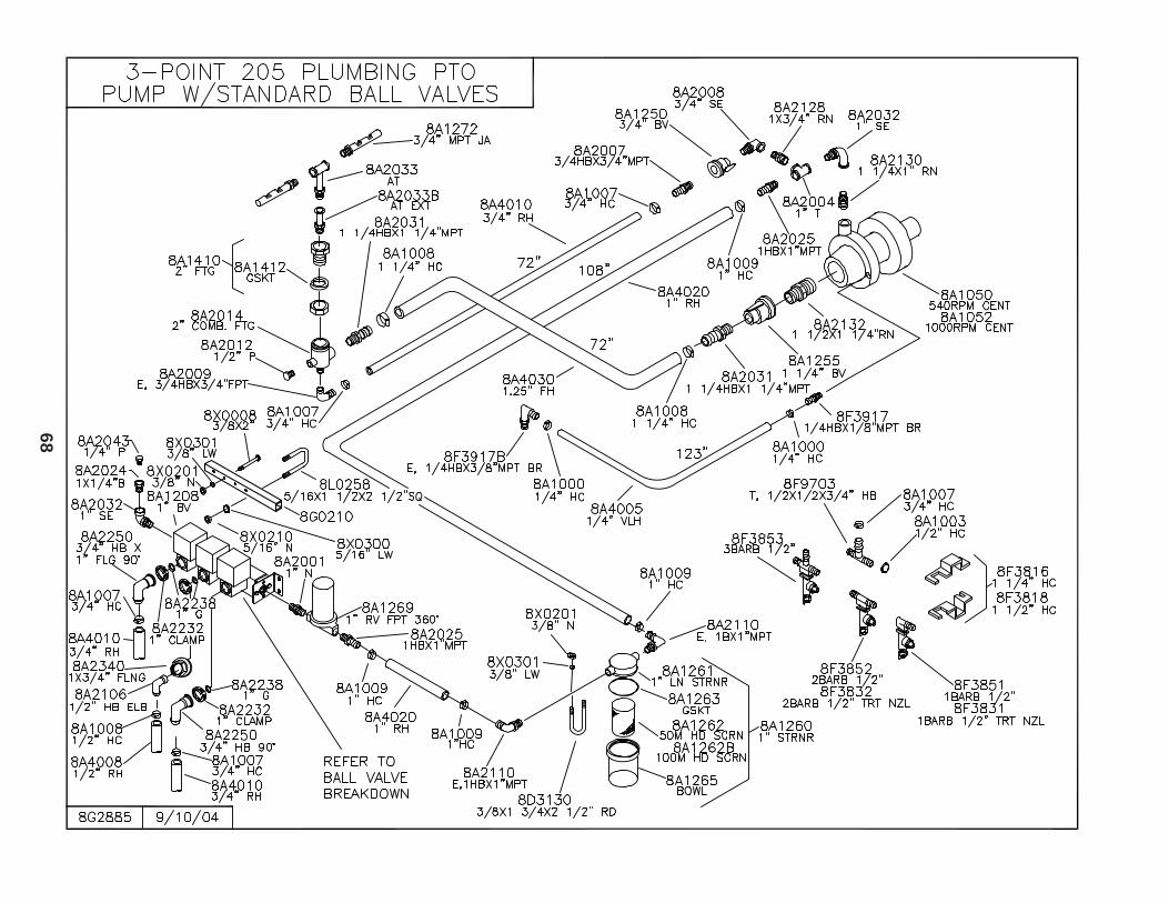
68
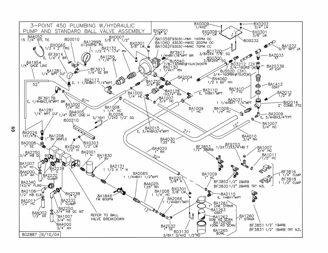
69
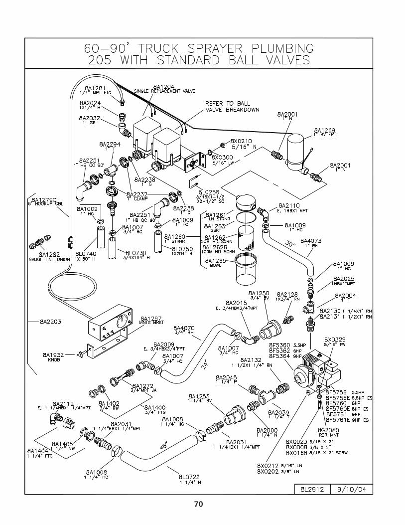
70
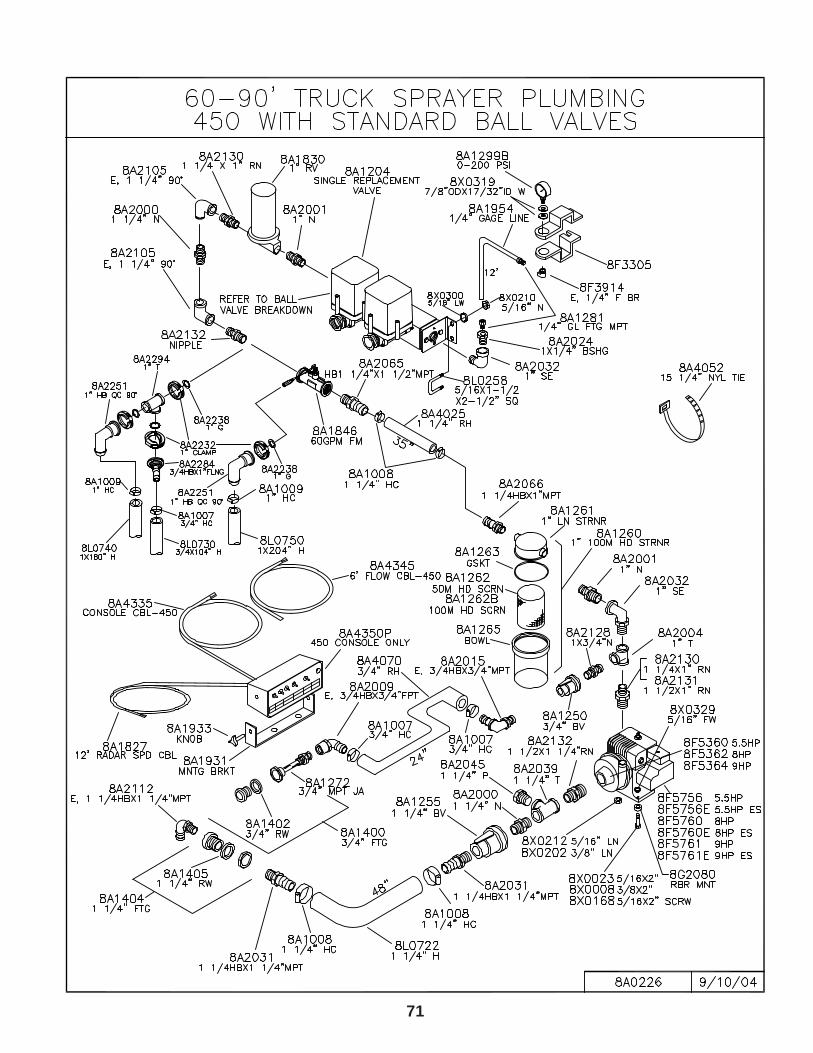
71
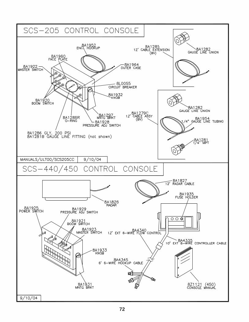
72
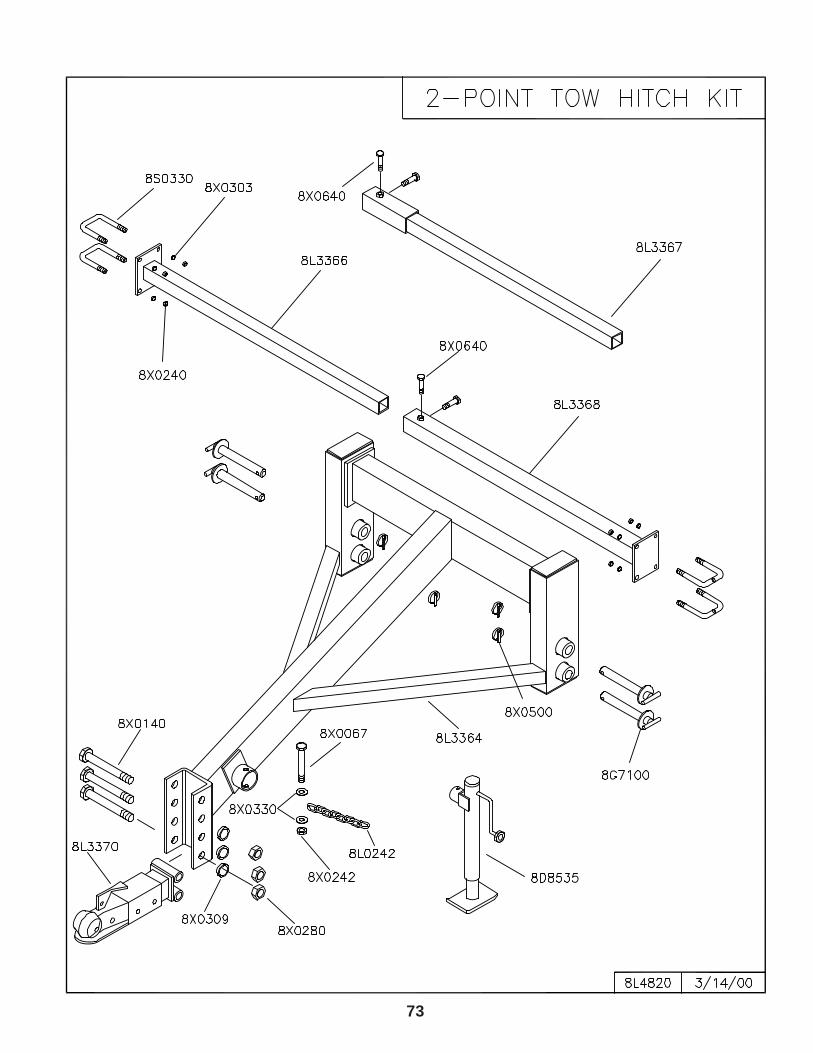
73
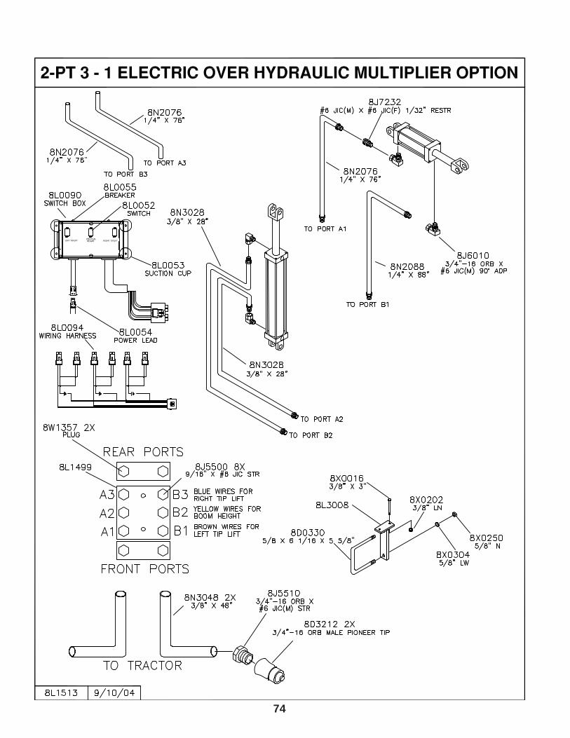
74
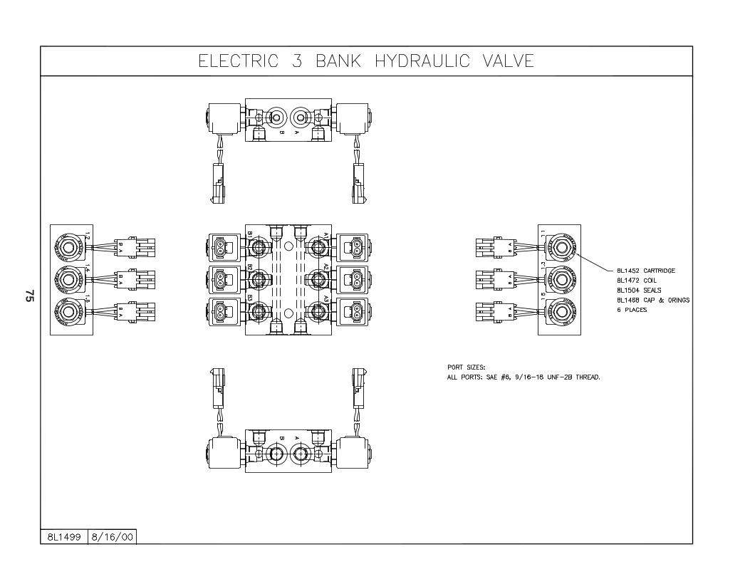
75
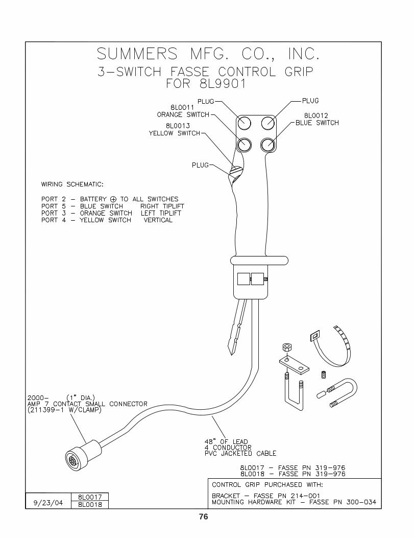
76
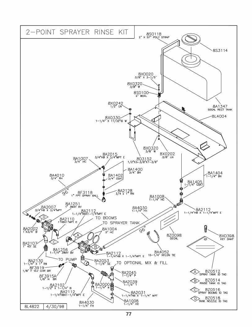
77
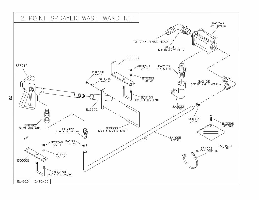
78
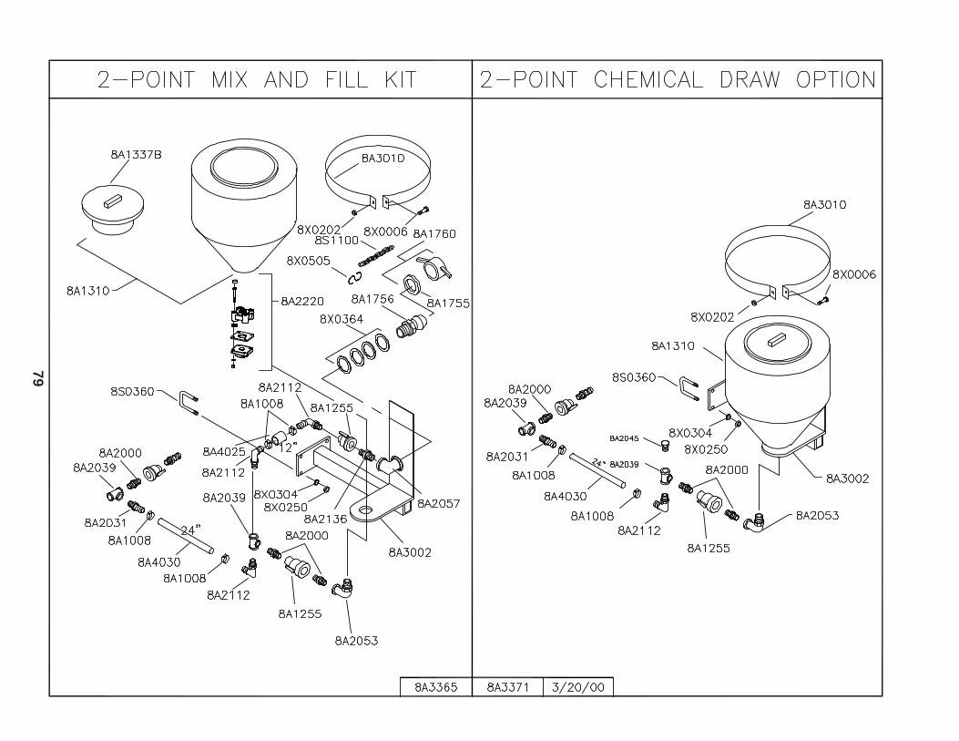
79
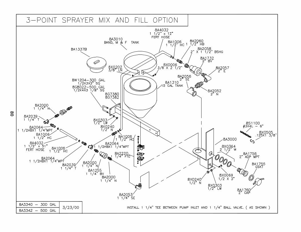
80
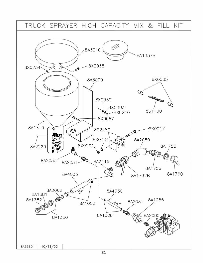
81
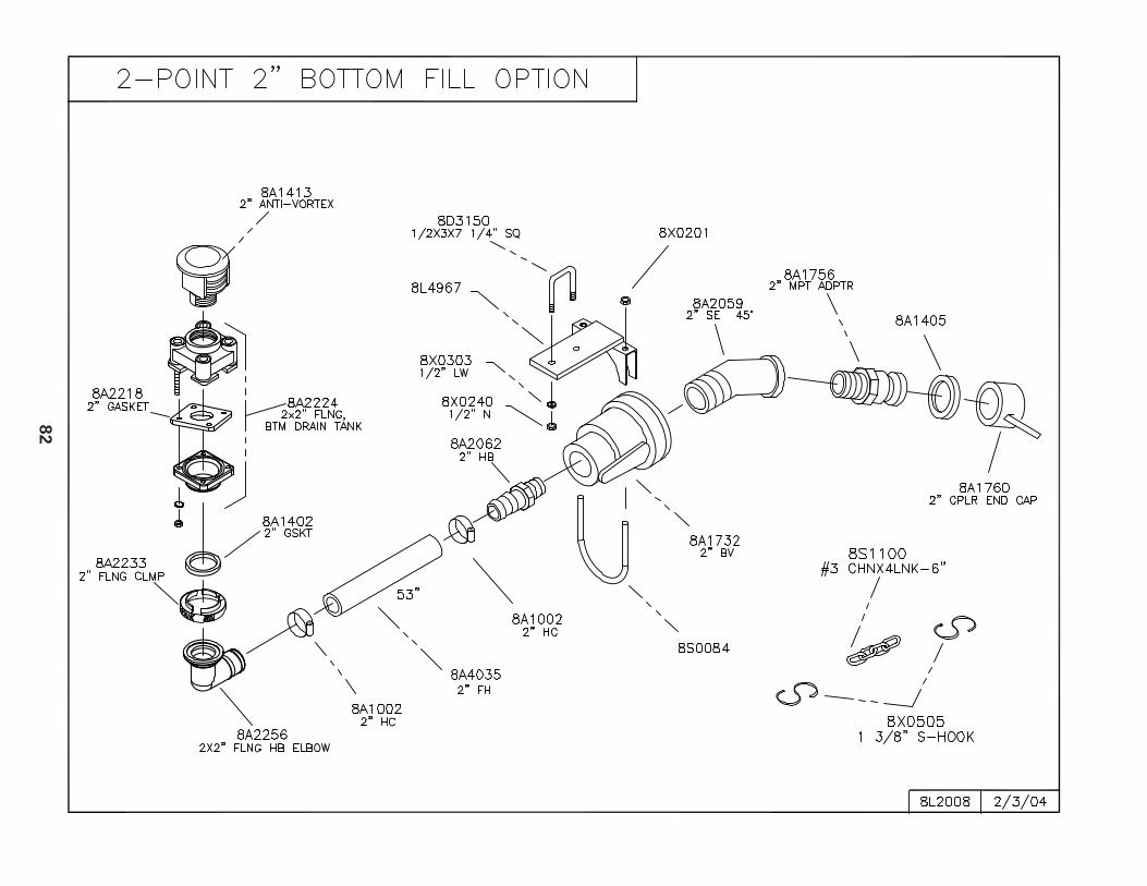
82
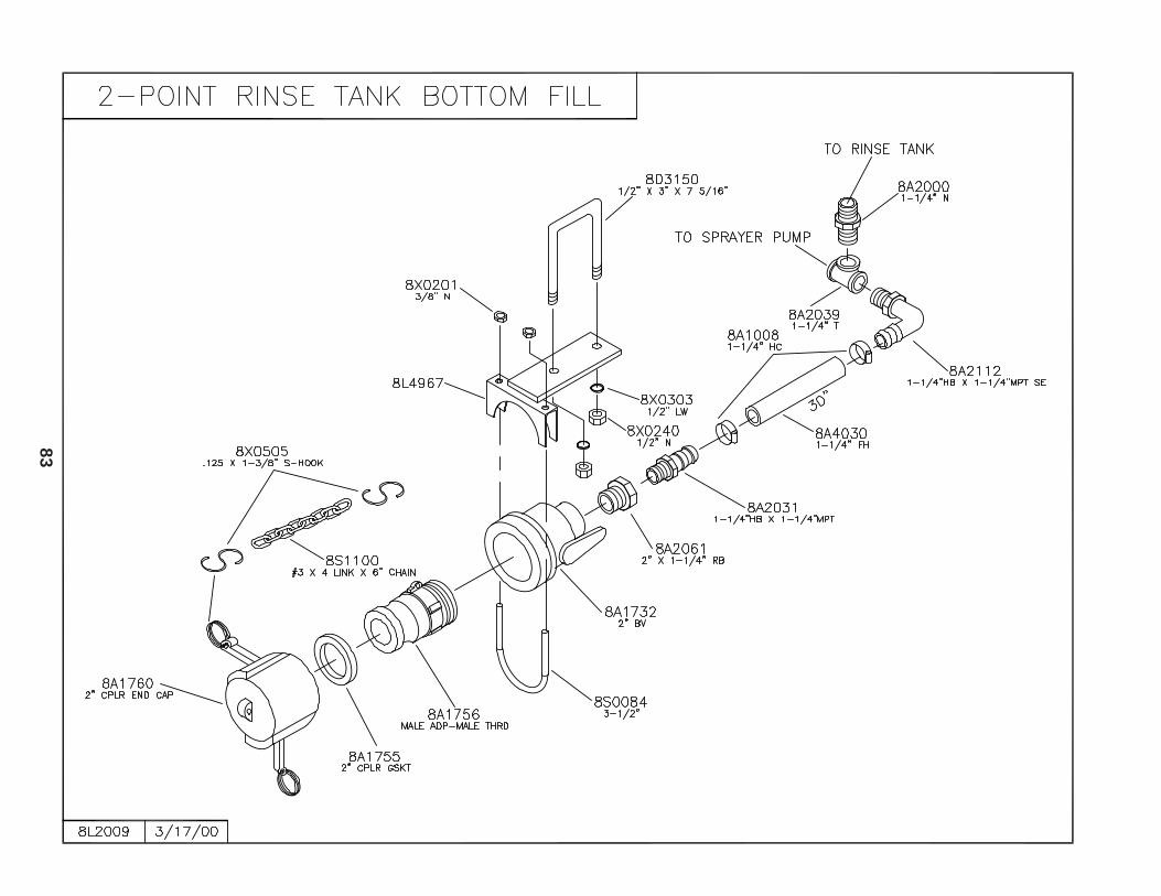
83
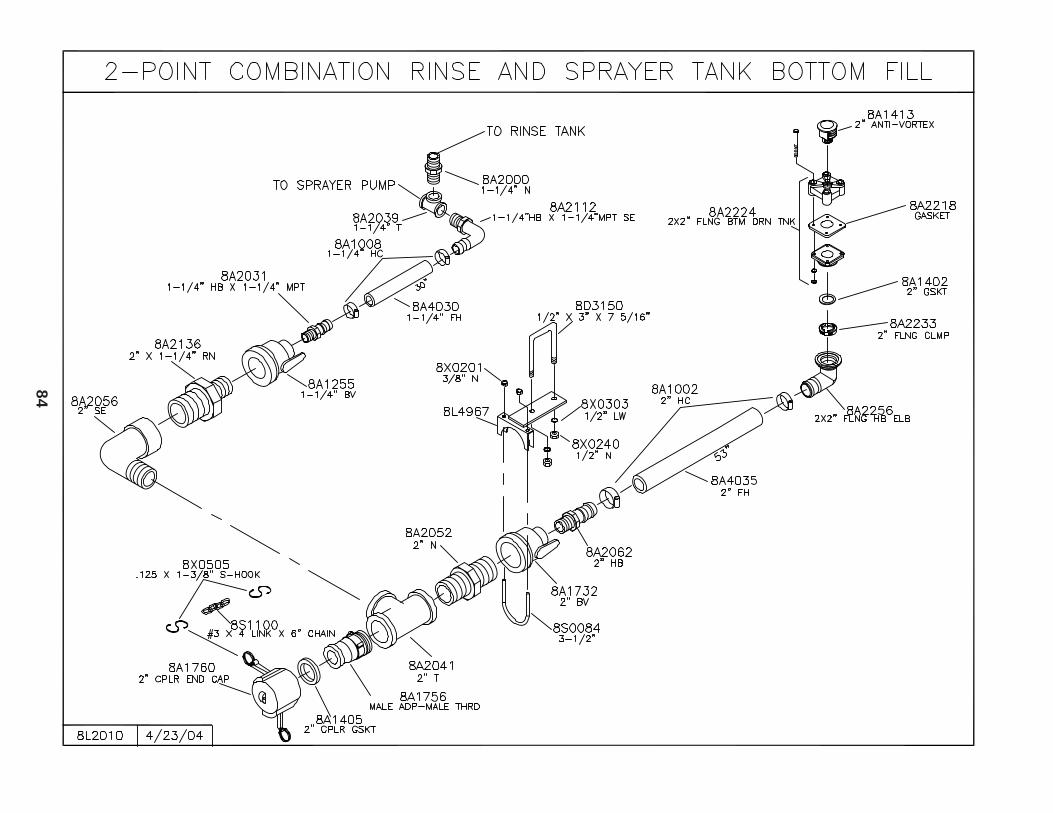
84
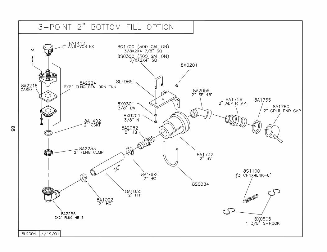
85
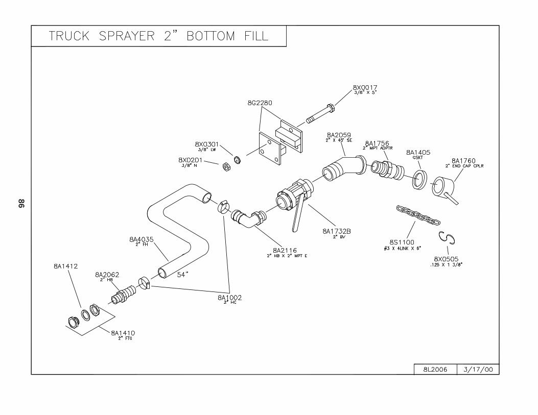
86
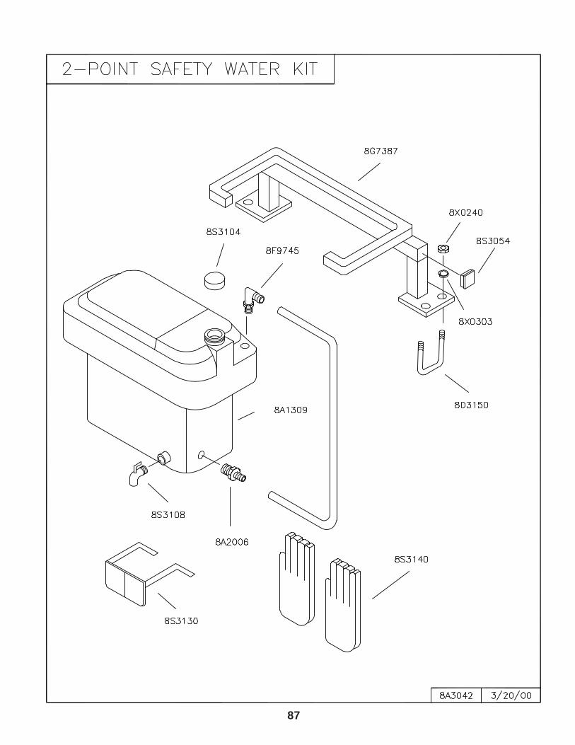
87
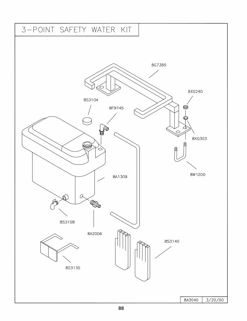
88
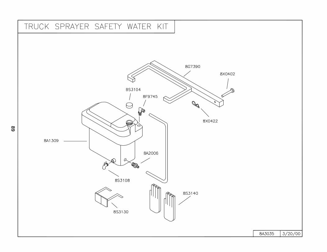
89
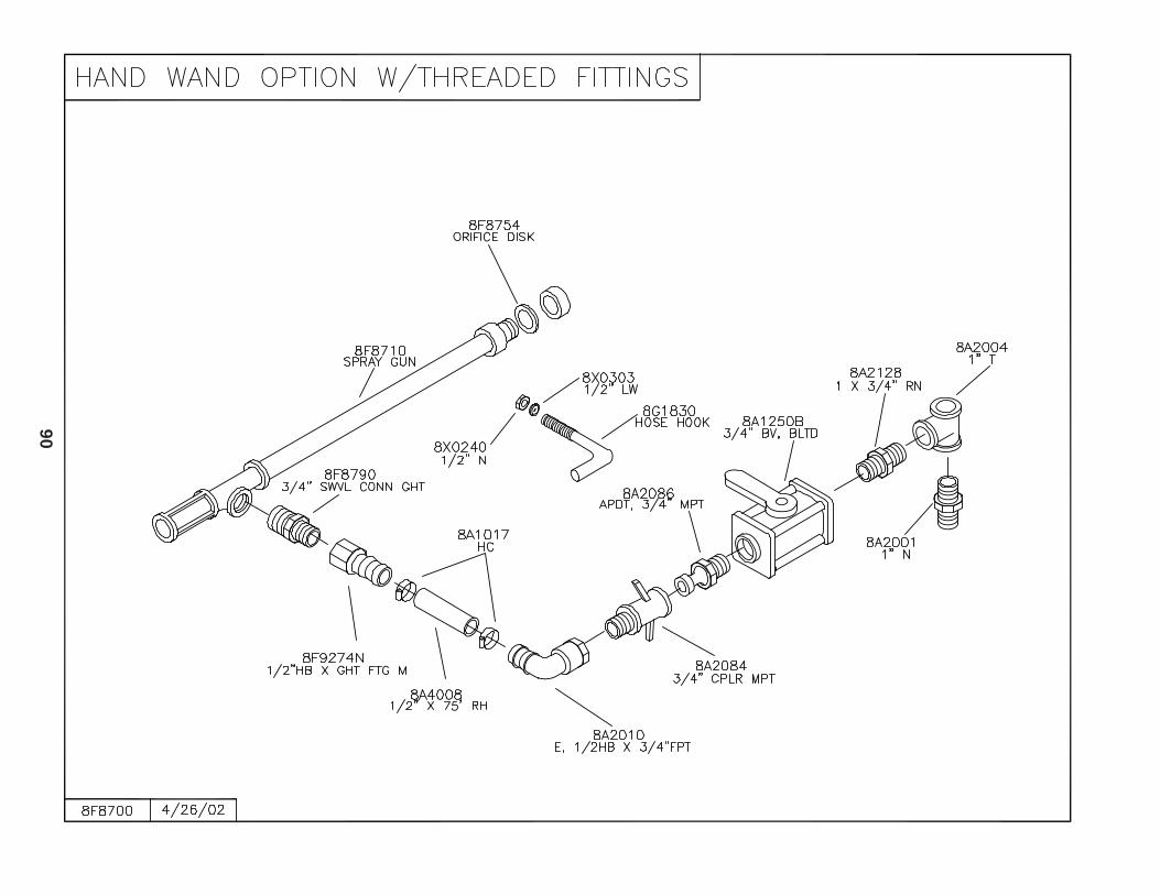
90
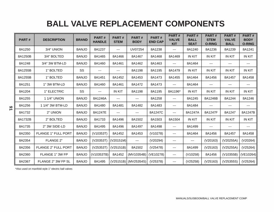
91
PART # DESCRIPTION BRANDPART #
HANDLEPART #STEM
PART #BODY
PART #END CAP
PART #VALVE
KIT
PART #BALLSEAT
PART #STEM
O-RING
PART #VALVEBALL
PART #BODY
O-RING
8A1250 3/4" UNION BANJO 8A1237 --- UV07254 8A1238 --- 8A1240 8A1236 8A1239 8A1241
8A1250B 3/4" BOLTED BANJO 8A1465 8A1466 8A1467 8A1468 8A1469 IN KIT IN KIT IN KIT IN KIT
8A1248 3/4" 3W BTM-LD BANJO 8A1460 8A1461 8A1462 8A1463 --- 8A1464 --- --- ---
8A1255B 1" BOLTED SS --- --- 8A1198 8A1195 8A1479 IN KIT IN KIT IN KIT IN KIT
8A1255B 1" BOLTED BANJO 8A1451 8A1452 8A1453 8A1473 8A1455 8A1464 8A1456 8A1457 8A1458
8A1251 1" 3W BTM-LD BANJO 8A1460 8A1461 8A1472 8A1473 --- 8A1464 --- --- ---
8A1204 1" ELECTRIC SS --- IN KIT 8A1198 8A1195 8A1196* IN KIT IN KIT IN KIT IN KIT
8A1255 1 1/4" UNION BANJO 8A1246A --- --- 8A1258 --- 8A1245 8A1246B 8A1244 8A1246
8A1256 1 1/4" 3W BTM-LD BANJO 8A1480 8A1481 8A1482 8A1483 --- 8A1484 --- --- ---
8A1732 2" UNION BANJO 8A1247E --- --- 8A1247C --- 8A1247A 8A1247F 8A1247 8A1247B
8A1732B 2" BOLTED BANJO 8A1733 8A1496 8A1502 8A1503 8A1504 IN KIT IN KIT IN KIT IN KIT
8A1735 2" 3W SIDE-LD BANJO 8A1495 8A1496 8A1497 8A1498 --- 8A1499 --- --- ---
8A2350 FLANGE 1" FULL PORT BANJO (V10353T) 8A1452 8A1453 (V10278) --- 8A1464 8A1456 8A1457 8A1458
8A2354 FLANGE 2" BANJO (V20353T) (V20151M) --- (V20294) --- --- (V20163) (V20255A) (V20264)
8A2356 FLANGE 2" FULL PORT BANJO (V25353T) (V25151B) 8A1502 (V25478) --- 8A1499 (V25163) (V25255A) (V25264)
8A2360 FLANGE 1" 3W FP BANJO (V10353TB) 8A1452 (MV10354B) (VE10278) --- (V10258) 8A1456 (V10355B) (VE10264)
8A2367 FLANGE 2" 3W FP SL BANJO 8A1495 (V25151B) (MV25354S) (V25378) --- (V25258) (V25163) (V25355S) (V25264)
*Also used on manifold style 1" electric ball valves
MANUALS/SUSBOOM/BALL VALVE REPLACEMENT COMP
BALL VALVE REPLACEMENT COMPONENTS
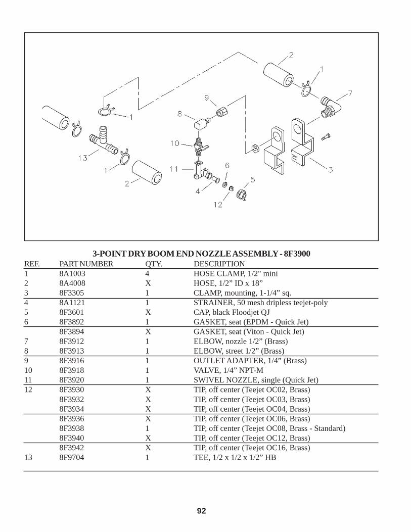
92
3-POINT DRY BOOM END NOZZLE ASSEMBLY - 8F3900REF. PART NUMBER QTY. DESCRIPTION1 8A1003 4 HOSE CLAMP, 1/2" mini2 8A4008 X HOSE, 1/2” ID x 18”3 8F3305 1 CLAMP, mounting, 1-1/4” sq.4 8A1121 1 STRAINER, 50 mesh dripless teejet-poly5 8F3601 X CAP, black Floodjet QJ6 8F3892 1 GASKET, seat (EPDM - Quick Jet)
8F3894 X GASKET, seat (Viton - Quick Jet)7 8F3912 1 ELBOW, nozzle 1/2” (Brass)8 8F3913 1 ELBOW, street 1/2” (Brass)9 8F3916 1 OUTLET ADAPTER, 1/4” (Brass)10 8F3918 1 VALVE, 1/4” NPT-M11 8F3920 1 SWIVEL NOZZLE, single (Quick Jet)12 8F3930 X TIP, off center (Teejet OC02, Brass)
8F3932 X TIP, off center (Teejet OC03, Brass)8F3934 X TIP, off center (Teejet OC04, Brass)8F3936 X TIP, off center (Teejet OC06, Brass)8F3938 1 TIP, off center (Teejet OC08, Brass - Standard)8F3940 X TIP, off center (Teejet OC12, Brass)8F3942 X TIP, off center (Teejet OC16, Brass)
13 8F9704 1 TEE, 1/2 x 1/2 x 1/2” HB
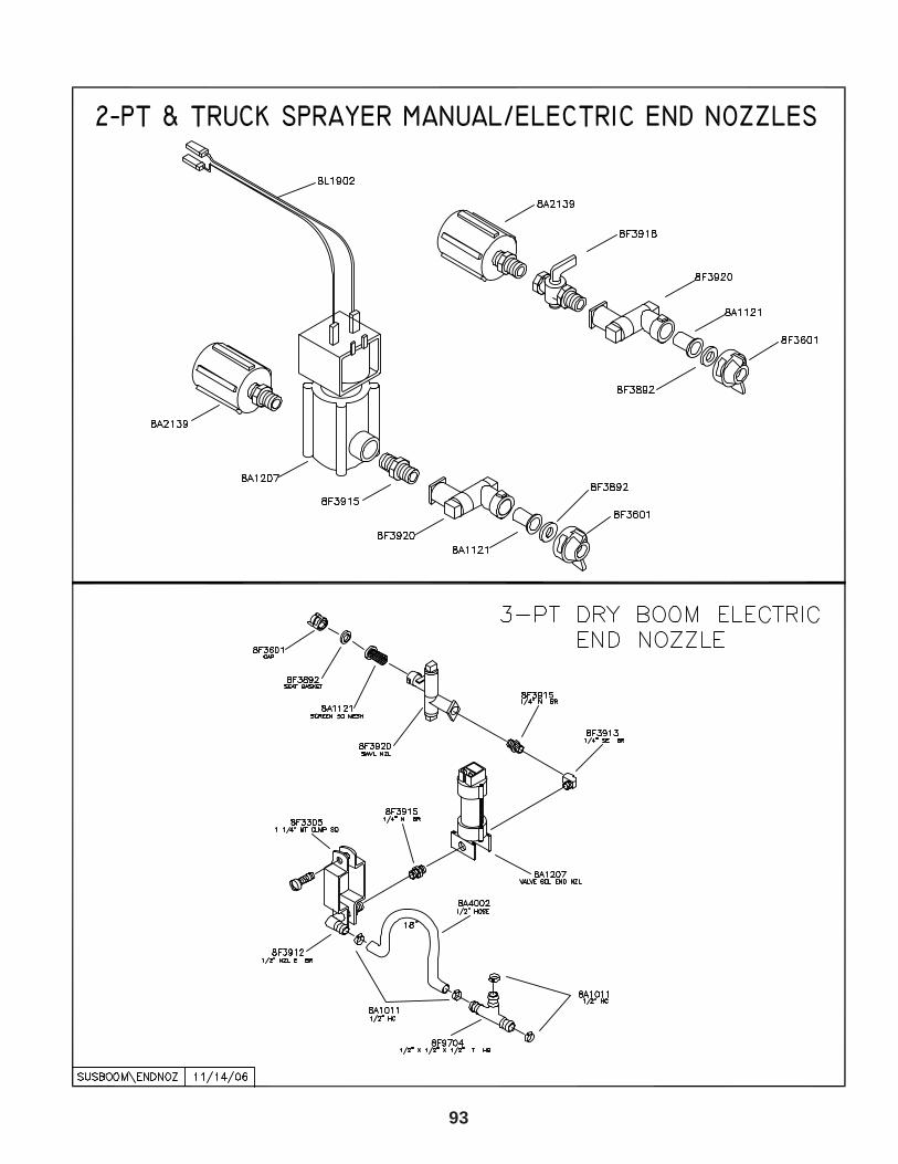
93
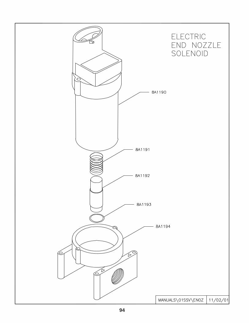
94
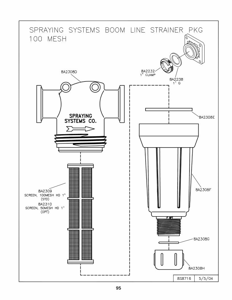
95

96
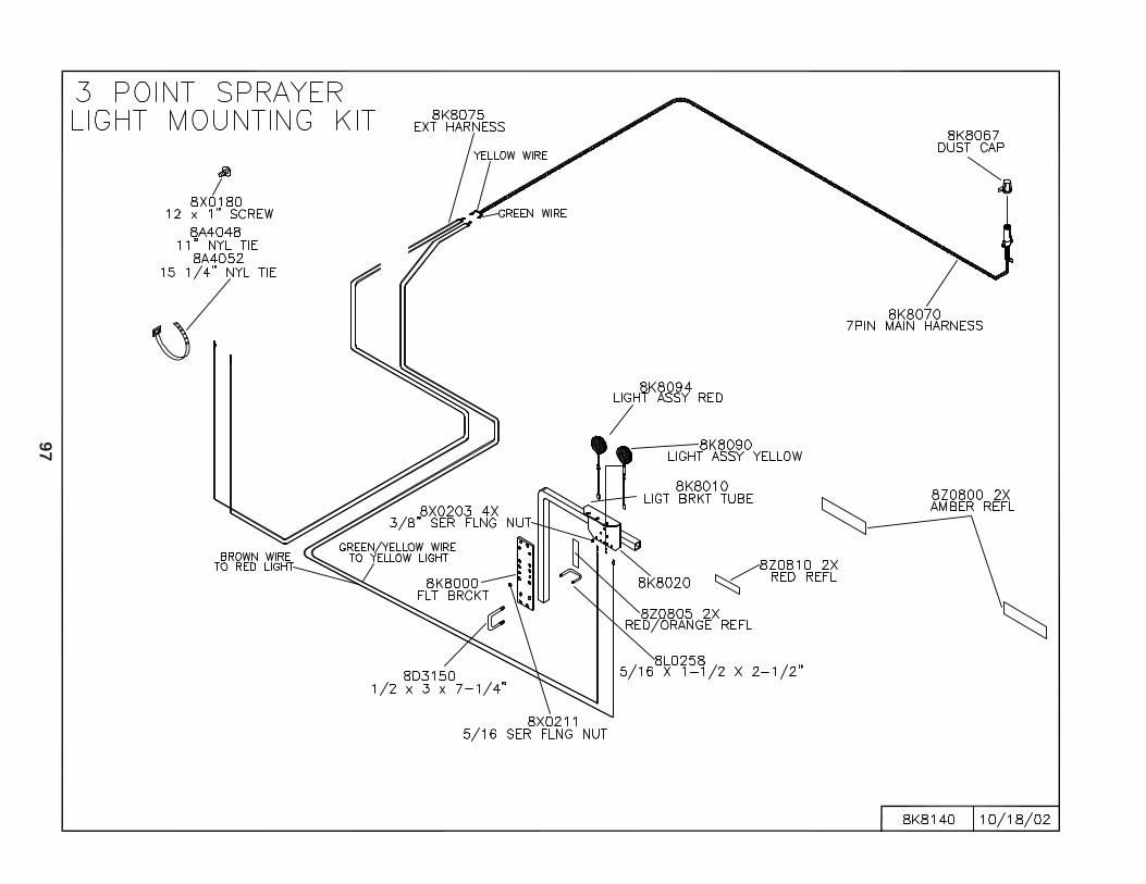
97
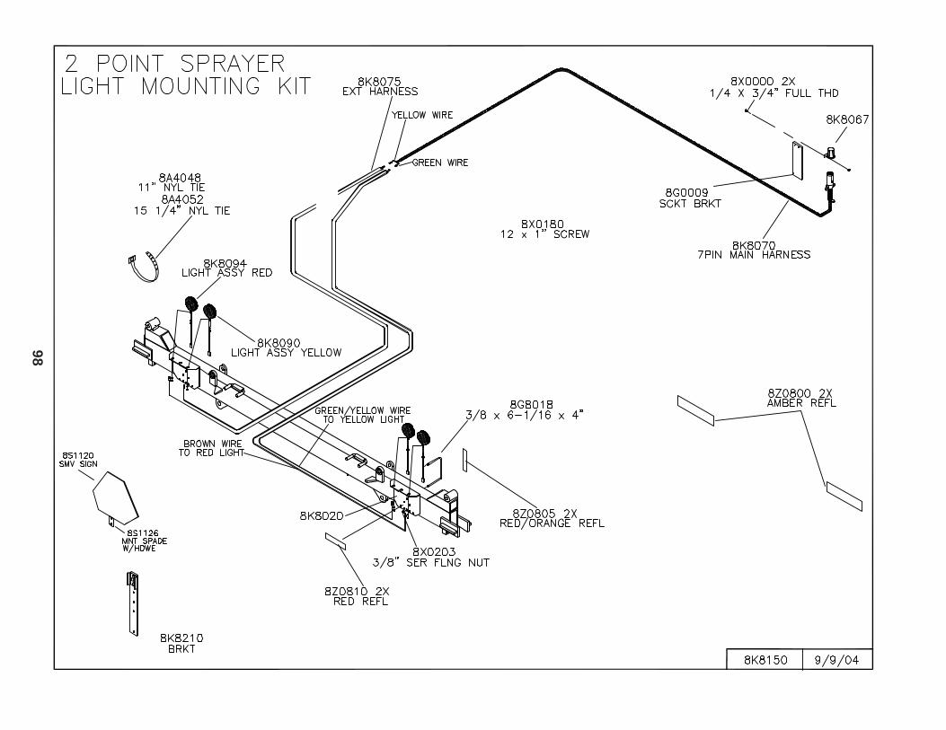
98
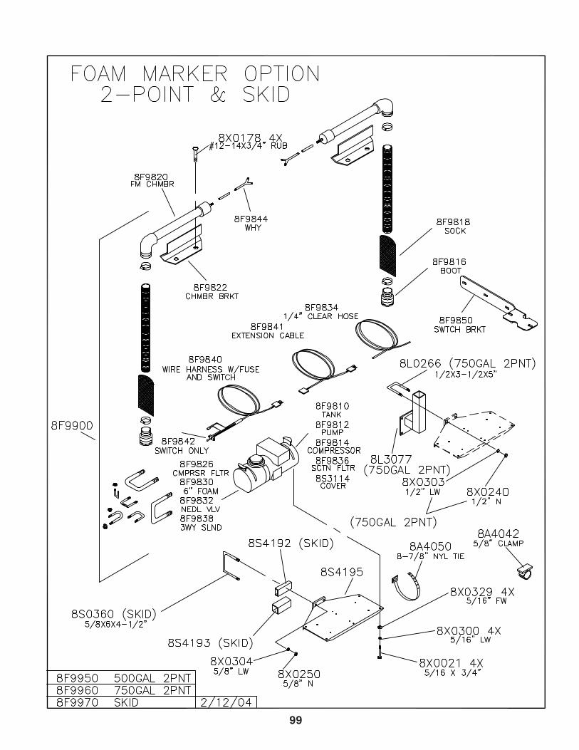
99
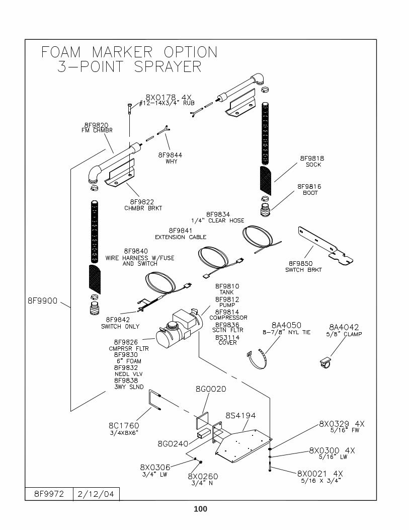
100
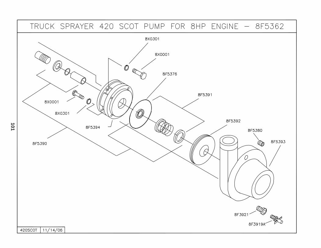
10
1
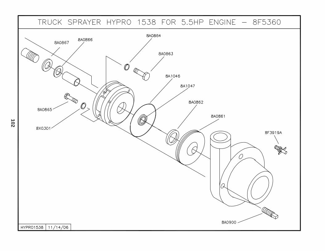
10
2
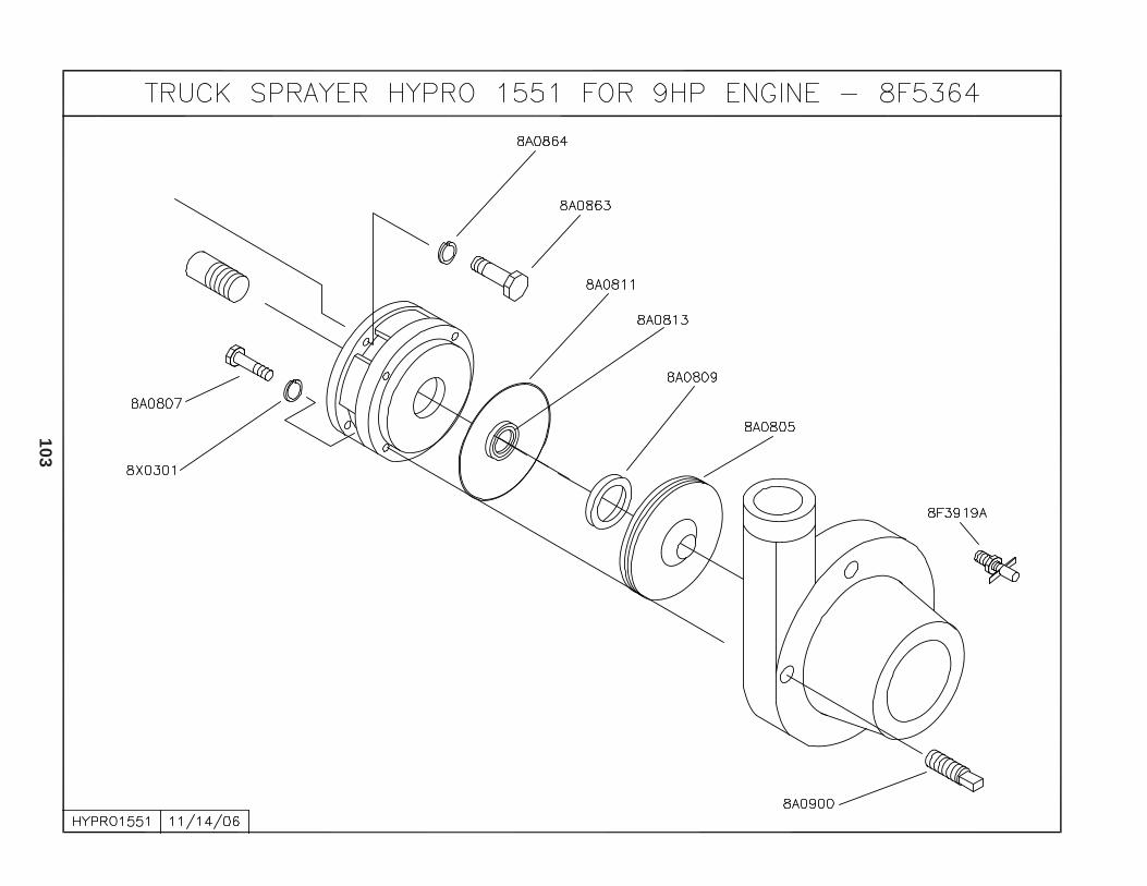
10
3
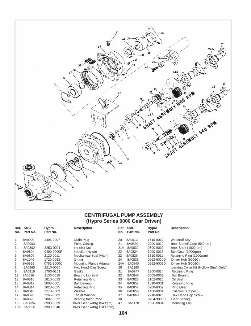
104
CENTRIFUGAL PUMP ASSEMBLY(Hypro Series 9000 Gear Driven)
Ref. SMC Hypro Description Ref. SMC Hypro DescriptionNo. Part No. Part No. No. Part No. Part No.
1 8A0900 2406-0007 Drain Plug 20 8A0912 1610-0012 Woodruff Key2 8A0903 Pump Casing 21 8A0830 3900-0010 Imp. Shaft/P.Gear (540rpm)3 8A0802 2253-0001 Impeller Nut 21A 8A0832 0500-9002 Imp. Shaft (1000rpm)4 8A0804 0400-9000P Impeller (Nylon) 22 8A0834 3900-0013 Sun Gear (1000rpm)5 8A0806 2120-0011 Mechanical Seal (Viton) 23 8A0836 1810-0011 Retaining Ring (1000rpm)6 8A1046 1720-0083 O-ring 24 8A0838 0562-9000D Driver Hub (9006C)7 8A0858 0752-9000C Mounting Flange Adapter 24A 8A0840 0562-9002D Driver Hub (9008C)8 8A0865 2210-0020 Hex Head Cap Screw 25 8A1180 Locking Collar Kit (Hollow Shaft Only)9 8A0816 1700-0101 Gasket 31 8A0847 1800-0014 Retaining Ring11 8A0816 2130-0018 Bearing Lip Seal 32 8A0848 2005-0002 Ball Bearing12 8A0810 1810-0013 Retaining Ring 33 8A0828 2102-0025 Oil Seal13 8A0812 2008-0001 Ball Bearing 34 8A0852 1810-0001 Retaining Ring14 8A0814 1820-0025 Retaining Ring 35 8A0854 3900-0009 Ring Gear16 8A0818 2270-0003 Washer 36 8A0856 1450-0004 Cushion Bumper17 8A0820 2265-0003 Thrust Washer 37 8A0860 2210-0026 Hex Head Cap Screw18 8A0822 2007-0022 Bearing Inner Race 38 0754-9000C Gear Casing19 8A0824 3900-0039 Driver Gear w/Brg (540rpm) 47 8A1178 1520-0034 Mounting Clip19A 8A0826 3900-0040 Driver Gear w/Brg (1000rpm)
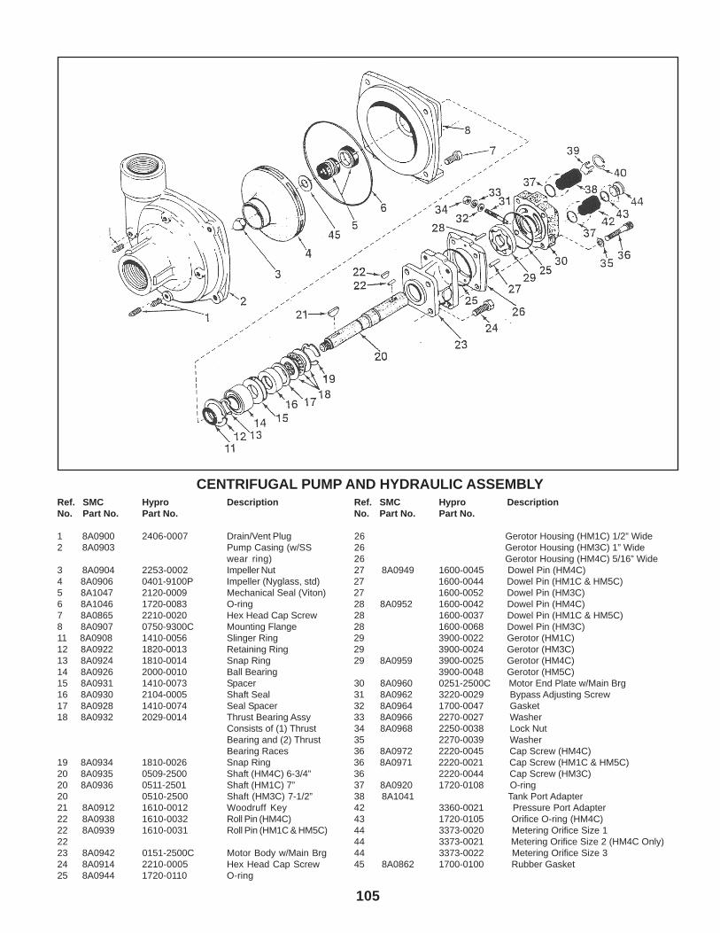
CENTRIFUGAL PUMP AND HYDRAULIC ASSEMBLYRef. SMC Hypro Description Ref. SMC Hypro DescriptionNo. Part No. Part No. No. Part No. Part No.
1 8A0900 2406-0007 Drain/Vent Plug 26 Gerotor Housing (HM1C) 1/2” Wide2 8A0903 Pump Casing (w/SS 26 Gerotor Housing (HM3C) 1” Wide
wear ring) 26 Gerotor Housing (HM4C) 5/16” Wide3 8A0904 2253-0002 Impeller Nut 27 8A0949 1600-0045 Dowel Pin (HM4C)4 8A0906 0401-9100P Impeller (Nyglass, std) 27 1600-0044 Dowel Pin (HM1C & HM5C)5 8A1047 2120-0009 Mechanical Seal (Viton) 27 1600-0052 Dowel Pin (HM3C)6 8A1046 1720-0083 O-ring 28 8A0952 1600-0042 Dowel Pin (HM4C)7 8A0865 2210-0020 Hex Head Cap Screw 28 1600-0037 Dowel Pin (HM1C & HM5C)8 8A0907 0750-9300C Mounting Flange 28 1600-0068 Dowel Pin (HM3C)11 8A0908 1410-0056 Slinger Ring 29 3900-0022 Gerotor (HM1C)12 8A0922 1820-0013 Retaining Ring 29 3900-0024 Gerotor (HM3C)13 8A0924 1810-0014 Snap Ring 29 8A0959 3900-0025 Gerotor (HM4C)14 8A0926 2000-0010 Ball Bearing 3900-0048 Gerotor (HM5C)15 8A0931 1410-0073 Spacer 30 8A0960 0251-2500C Motor End Plate w/Main Brg16 8A0930 2104-0005 Shaft Seal 31 8A0962 3220-0029 Bypass Adjusting Screw17 8A0928 1410-0074 Seal Spacer 32 8A0964 1700-0047 Gasket18 8A0932 2029-0014 Thrust Bearing Assy 33 8A0966 2270-0027 Washer
Consists of (1) Thrust 34 8A0968 2250-0038 Lock NutBearing and (2) Thrust 35 2270-0039 WasherBearing Races 36 8A0972 2220-0045 Cap Screw (HM4C)
19 8A0934 1810-0026 Snap Ring 36 8A0971 2220-0021 Cap Screw (HM1C & HM5C)20 8A0935 0509-2500 Shaft (HM4C) 6-3/4” 36 2220-0044 Cap Screw (HM3C)20 8A0936 0511-2501 Shaft (HM1C) 7” 37 8A0920 1720-0108 O-ring20 0510-2500 Shaft (HM3C) 7-1/2” 38 8A1041 Tank Port Adapter21 8A0912 1610-0012 Woodruff Key 42 3360-0021 Pressure Port Adapter22 8A0938 1610-0032 Roll Pin (HM4C) 43 1720-0105 Orifice O-ring (HM4C)22 8A0939 1610-0031 Roll Pin (HM1C & HM5C) 44 3373-0020 Metering Orifice Size 122 44 3373-0021 Metering Orifice Size 2 (HM4C Only)23 8A0942 0151-2500C Motor Body w/Main Brg 44 3373-0022 Metering Orifice Size 324 8A0914 2210-0005 Hex Head Cap Screw 45 8A0862 1700-0100 Rubber Gasket25 8A0944 1720-0110 O-ring
105
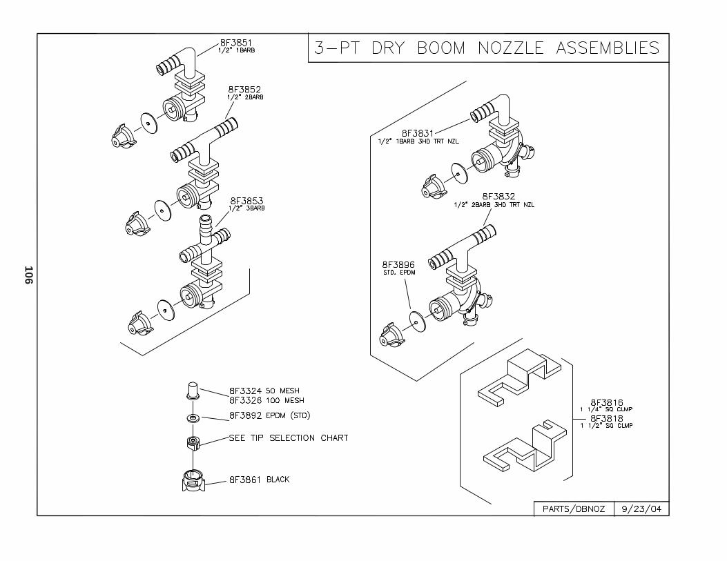
10
6
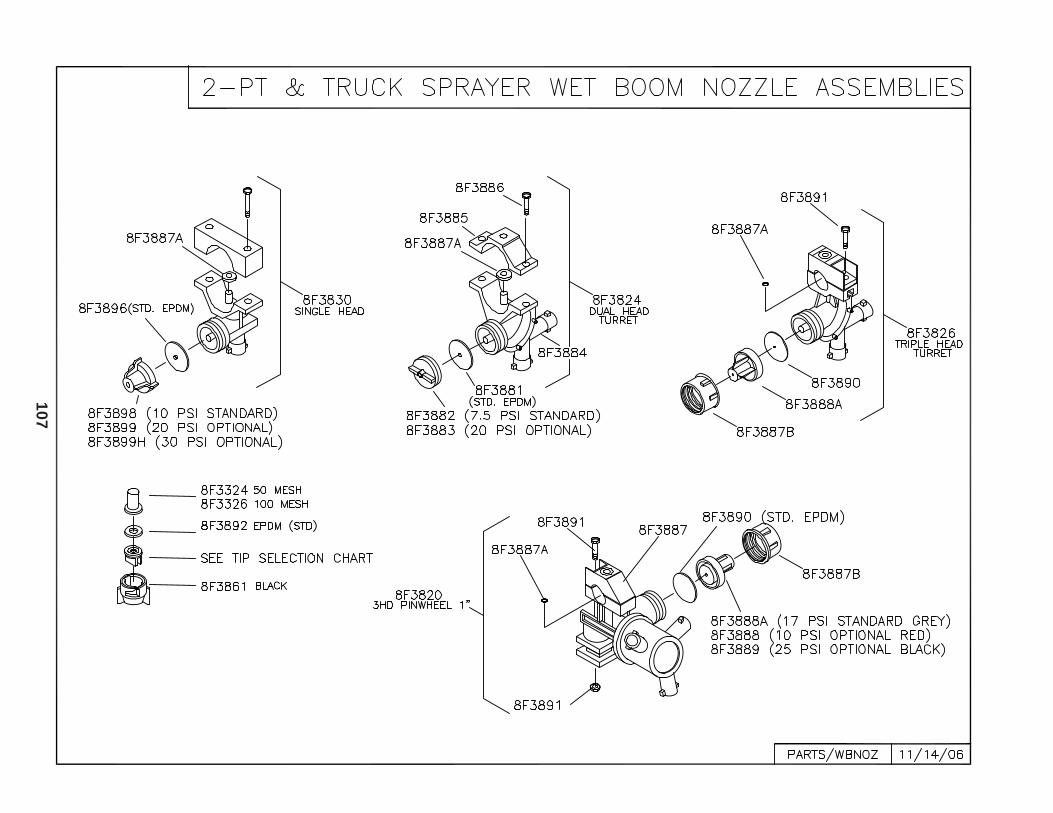
10
7
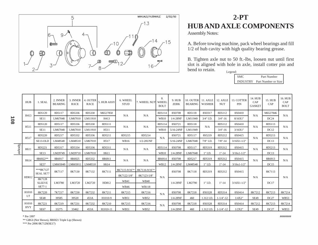
2-PTHUB AND AXLE COMPONENTSAssembly Notes:
A. Before towing machine, pack wheel bearings and fill1/2 of hub cavity with high quality bearing grease.
B. Tighten axle nut to 50 ft.-lbs, loosen nut until firstslot is aligned with hole in axle, install cotter pin andbend to retain. Legend:
SMC Part Number
INDUSTRY Part Number or Size
10
8
HUB 1. SEAL2. INNER BEARING
3. INNER RACE
4. OUTER RACE
5. HUB ASSY6. WHEEL
STUD7. WHEEL NUT
8. WHEEL BOLT
9. HUB ZERK
10. OUTER BEARING
11. AXLE WASHER
12. AXLE NUT
13. COTTER PIN
14. HUB CAP
GASKET
15. HUB CAP
16. HUB CAP
BOLT
8D5120 8D5117 8D5336 8D5330 M6527850 8D5114 8X0708 8D5118 8X0317 8D5112 8X0410 M6527846
SE11 LM67048 LM67010 LM11910 H413 WB10 1/4-28NF LM11949 3/4" I.D. 3/4"-16 8/16X1" DC24
8D5120 8D5117 8D5336 8D5330 8D5111 8D5114 8X0721 8D5118 8D5112 8X0410 8D5113
SE11 LM67048 LM67010 LM11910 H511 WB10 5/16-24NF LM11949 3/4"-16 3/16X1" DC12
8D5220 8D5217 8D5332 8D5336 8D5211 8D5215 8D5214 8X0721 8D5117 8S5219 8D5212 8X0415 8D5213
SE13-OLD LM48548 LM48510 LM67010 H517 WB16 1/2-20UNF 5/16-24NF LM67048 7/8" I.D. 7/8"-14 3/16X1-1/2" DC13
8D5221 8D5317 8D5334 8D5336 8D5311 8D5114 8X0708 8D5117 8D5319 8D5312 8X0415 8D5213
SE13 LM29749 LM29710 LM67010 H611 WB10 1/4-28NF LM67048 1" I.D. 1"-14 3/16x1-1/2" DC13
8R6922** 8R6917 8R6925 8D5332 8R6911 8R6914 8X0708 8D5217 8D5319 8D5312 8X0415 8R6913
SE57 LM603049 LM603011 LM48510 H614 WB12 1/4-28NF LM48548 1" I.D. 1"-14 3/16x1-1/2" DC15
8K7115-9/16"* 8K7116-9/16"*
8K7122-5/8" 8K7123-5/8"
WB41 WB40
WB46 WB118
8K7220 7K7217 8K7230 8K7232 8K7211 8K7215 8K7216 8X0708 8K7218 8X0328 8D5314 8X0414 8K7212 8K7213 8K7214
SE48 39585 39520 453A H1010-9 WB51 WB52 1/4-28NF 460 1.312 I.D. 1-1/4"-12 1/4X2" SE49 DC27 WB53
8K7221 8K7219 8K7231 8K7232 8K7210 8K7215 8K7216 8X0708 8K7218 8X0328 8D5314 8X0414 8K7212 8K7213 8K7214
SE67 33275 33462 453A H1010-11 WB51 WB52 1/4-28NF 460 1.312 I.D. 1-1/4"-12 1/2X2" SE49 DC27 WB53
* Pre 1997 ########** GBGI (Not Shown), 8R6921 Triple Lip (Shown)*** Pre 2006 8K7120(SE17)
N/A
N/A N/A
N/A
N/A
N/AH611
H614
H413 N/A
H517
N/A
N/A
N/A N/A N/A
H511 N/A N/A N/A N/A N/A
N/A N/A N/A
HD812
***8K7127SEAL SE77
8K7128SLEEVE SE77-1
8K7117
LM3780
8K7130
LM3720
8K7132
LM2720
8K7111
HD812
N/A
8X0708
1/4-28NF
8K7118
LM2790
8D5319
1" I.D.
8D5312
1"-14
N/A
H1010 LT
N/A
N/AH1010 HVY
8X0415
3/16X1-1/2"
N/A
8K7113
DC17
Sprayer
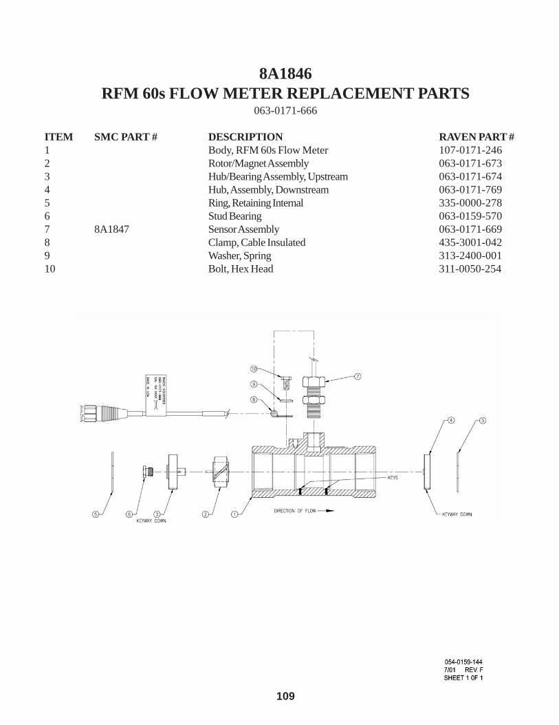
109
8A1846RFM 60s FLOW METER REPLACEMENT PARTS
063-0171-666
ITEM SMC PART # DESCRIPTION RAVEN PART #1 Body, RFM 60s Flow Meter 107-0171-2462 Rotor/Magnet Assembly 063-0171-6733 Hub/Bearing Assembly, Upstream 063-0171-6744 Hub, Assembly, Downstream 063-0171-7695 Ring, Retaining Internal 335-0000-2786 Stud Bearing 063-0159-5707 8A1847 Sensor Assembly 063-0171-6698 Clamp, Cable Insulated 435-3001-0429 Washer, Spring 313-2400-00110 Bolt, Hex Head 311-0050-254
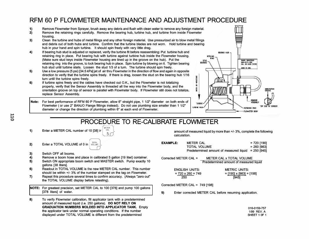
110

111
10/1/04 SUMMERS MFG. CO., INC.
Stock # Description1S1516 POLY 16" WIDE PER/FT1S1518 PERFORATED POLY 18" WIDE PER/FT8A0802 IMPELLER NUT8A0804 IMPELLER (PLASTIC)8A0805 IMPELLER 1551 HYPRO PUMP8A0806 MECHANICAL SEAL VITON8A0807 BOLT HYPRO 1551 PUMP HOUSING8A0809 GASKET 1551 HYPRO PUMP8A0810 BEARING RETAINER RING8A0811 O-RING HYPRO 1551 PUMP8A0812 BALL BEARING8A0813 SEAL VITON 1551 HYPRO PUMP8A0814 RETAINING RING8A0816 LIP SEAL BEARING 9006C/9008C8A0818 WASHER8A0820 THRUSTWASHER8A0822 BEARING INNER RACE8A0824 DRIVER GEAR WITH BEARING 9006C8A0826 DRIVER GEAR WITH BEARING 9008C8A0828 OIL SEAL DRIVER 9006C/9008C8A0830 PINION GEARED IMPELLER SHAFT8A0832 IMPELLER SHAFT8A0834 SUN GEAR8A0836 RETAINING RING (FOR SUN GEAR)8A0838 DRIVER HUB 9006C8A0840 DRIVER HUB 9008C8A0847 RETAINING RING8A0848 BALL BEARING8A0850 SLINGER8A0852 RETAINING RING8A0854 RING GEAR8A0856 CUSHION BUMPER8A0858 GEAR CASING8A0860 HEX HEAD CAPSCREW8A0861 IMPELLER 1538 HYPRO PUMP8A0862 GASKET 1538 HYPRO PUMP IMPELR8A0863 BOLT HYPRO 1538 PUMP - ENGINE8A0864 BOLT SEAL HYPRO 1538 PUMP8A0865 BOLT HYPRO 1538 FLANGE-CASING8A0866 SPACER HYPRO 1538 PUMP8A0867 BEARING SHIELD HYPRO 15388A0900 DRAIN/VENT PLUG8A0902 PUMP CASTING 1-1/2" X 1-1/4"8A0903 PUMP CASTING BODY 220 X 200 FLNGD8A0904 IMPELLER NUT8A0906 IMPELLER8A0907 MOUNTING FLANGE8A0908 SLINGER RING8A0912 WOODRUFF KEY8A0914 HEX HEAD CAPSCREW8A0920 O-RING FOR HYDRAULIC PORTS8A0922 RETAINING RING8A0924 SNAP RING8A0926 BALL BEARING8A0928 SPACER8A0930 SHAFT SEAL
8A0931 SEAL SPACER8A0932 THRUST BEARING ASSEMBLY8A0934 SNAP RING8A0935 SHAFT HM2&48A0936 SHAFT HM18A0937 SHAFT HM38A0938 ROLL PIN HM2&48A0940 WOODRUFF KEY HM38A0942 MOTOR FRONT BODY8A0944 O-RING8A0948 GEROTOR HOUSING HM48A0949 DOWEL PIN HM2&48A0952 DOWEL PIN HM2&48A0959 GEROTOR HM48A0960 MOTOR END PLATE8A0962 BYPASS ADJUSTING SCREW8A0964 GASKET8A0966 WASHER8A0968 LOCK NUT8A0971 SOCKET HEAD CAPSCREW HM18A0972 SOCKET HEAD CAPSCREW HM2&48A0974 TANK PORT ADAPTER8A1000 HOSE CLAMP 1/4" MINI8A1002 HOSE CLAMP 2" #368A1004 HOSE CLAMP 5" #728A1006 HOSE CLAMP 1-1/2" #248A1007 HOSE CLAMP 3/4" #128A1008 HOSE CLAMP 1-1/4" #208A1009 HOSE CLAMP 1" #168A1017 HOSE CLAMP SIZE J .820- .9308A1040 TANK CHECK VALVE ASSEMBLY8A1044 PORT ADAPTER HYPRO PUMP8A1046 O-RING (BUNA-N)8A1047 MECHANICAL SEAL (VITON)8A1050 C9006 540 RPM CENT PUMP VITON8A1052 C9008 1000 RPM CENT PUMP VITON8A1056F 9303C-HM1C CNTRFGL FLGD HYDPMP8A1057 9303S-HM1C CNTRFGL PUMP HYDDRV8A1060 9303C-HM3C CNTRFGL PUMP HYDDRV8A1062F 9303C-HM4C CNTRFGL FLGD HYDPMP8A1078 ORIFICE O-RING8A1080 METERING ORIFICE SIZE #18A1081 METERING ORIFICE SIZE #28A1082 METERING ORIFICE SIZE #38A1121 DRIPLESS SCREEN 50 MESH8A1178 MOUNTING CLIP HYPRO PTO PUMP8A1180 LOCKING COLLAR KIT PTO PUMP8A1190 ELEC. END NOZZLE COIL WP8A1191 ELEC. END NOZZLE SPRING8A1192 ELEC. END NOZZLE PLUNGER VITON8A1193 ELEC. END NOZZLE VITON O-RING8A1194 ELEC. END NOZZLE VALVE BODY8A1195B ELEC BVALVE 1" FLANGE OUTLET8A1195C SCREW SS HEX HEAD CAP 3"8A1195D SCREW SS PHILLIPS PAN HEAD 3"8A1196 ELECTRIC BALLVALVE REBUILD KIT8A1198 ELEC. BALL VALVE NYLON BODY8A1198A ELEC BALL VALVE MANIFOLD BODY8A1205 MOTOR ONLY 344 BVLVE 25 RPM

112
8A1208 1" TRPL BVALVE MANIFOLD W/CONT8A1208A INLET 1" NPT BALLVALVE MANIFOLD8A1208B INNER CONNECTOR BVALV MANIFOLD8A1208C 0-RING BODY TO BODY BVLV MANIF8A1208D 1" DBL BVALVE MANIFOLD W/CONT8A1400 BANJO 3/4" FITTING COMPLETE8A1402 GASKET EDPM 3/4 & 1-1/2" BANJO8A1404 BANJO 1-1/4" FITTING COMPLETE8A1405 GASKET EDPM 1-1/4 & 2" BANJO8A1410 BANJO 2" FITTING COMPLETE8A1412 GASKET EDPM 2 & 3" BANJO8A1413 BANJO 2" ANTI-VORTEX NO SCREEN8A1414 TRANSMITTER ONLY REMOTE CNTRL8A1417 MNT BRCKT ONLY REMOTE CONTROL8A1420 REMOTE CONTROL 12VDC PKG8A1445 SEAL 16" ARAG HINGED COVER8A1446 16" HINGED CVR LESS HANDL PREC8A1447B RED ARM W/BAFFLE FOR ARAG COVR8A1448 16" HINGED FILLWELL RING PREC8A1450 PIN HINGED COVER8A1460 HANDLE (BANJO) 3/4 & 1" 3W BV 98-8A1461 STEM (BANJO) 3/4 & 1" 3W BV 98-8A1462 BODY (BANJO) 3/4" 3WAY BV 98-8A1463 END CAP(BANJO) 3/4" 3WAY BV 98-8A1464 BLLSEAT(BANJO) 3/4 & 1" 3W BV 98-8A1465 HANDLE (BANJO) 3/4" BLTD BV 98-8A1466 STEM (BANJO) 3/4" BLTD BV 98-8A1467 BODY (BANJO) 3/4" BLTD BV 98-8A1468 END CAP(BANJO) 3/4" BLTD BV 98-8A1469 VLV KIT(BANJO) 3/4" BLTD BV 98-8A1472 BODY (BANJO) 1" 3-WAY BV 98-8A1473 END CAP (BANJO) 1" 3-WAY BV 98-8A1475 HANDLE (POLY-SS) 1" BLTD BV 95-8A1479 SPARE PARTS KIT 1" BLTD BV 95-8A1480 HANDLE (BANJO) 1-1/4" 3W BV 98-8A1481 STEM (BANJO) 1-1/4" 3W BV 98-8A1482 BODY (BANJO) 1-1/4" 3W BV 98-8A1483 END CAP (BANJO) 1-1/4" 3W BV 98-8A1485 HANDLE (POLY-SS) 1-1/2" BV 95-8A1486 STEM (POLY-SS) 1-1/2" BV 95-8A1487 BODY (POLY-SS) 1-1/2" BV 95-8A1488 END CAP (POLYPRO) 1-1/2" BV 95-8A1489 SPARE PRTS KIT-SS 1-1/2" BV 95-8A1492 BODY (BANJO) 2" UNION BV -8A1495 HANDLE (BANJO) 2" 3-WAY BV 98-8A1496 STEM (BANJO) 2" 3-WAY BV 98-8A1497 BODY (BANJO) 2" 3-WAY BV 98-8A1498 END CAP (BANJO) 2" 3-WAY BV 98-8A1499 BLLSEAT (BANJO) 2" 3-WAY BV 98-8A1502 BODY (BANJO) 2" BLTD BV -8A1503 END CAP(BANJO) 2" BLTD BV -8A1504 VLV KIT(BANJO) 2" BLTD BV -8A1550 1.5"" FLANGED INLET CAP KZ BVLV8A1552 1"" FLANGED OUTLET CAP KZ BVLV8A1554 3/8" GAUGE PORT END CAP KZ BV8A1556 REPAIR KIT KZ FLANGED MTR VLV8A1558 MOTOR ASSY KZ FLANGED MTR VLV8A1562 1" KZ TRPL BVLV MANIFOLD W/CON8A1732 BALL VALVE 2" UNION
8A1732B BALL VALVE 2" BOLTED8A1733 HANDLE (BANJO) 2" BLTD BV -8A1735 BALL VALVE 2" 3-WAY SL8A1756 ADAPTER 2" MPT8A1760 COUPLER END CAP 2"8A1826 RADAR GUN W/CBL SPEED SENSOR PKG8A1827 CABLE RADAR SPEED SENSOR 12'8A1830 REGULATING VALVE RAVEN 1"8A1846 FLOWMETER 60GPM POLY8A2045 PLUG 1-1/4”8A2106 ELBOW 1” 90 DEGREE8A2110 ELBOW 1" HB X 1 MPT8A2111 ELBOW 1" HB X 1-1/4" MPT8A2112 ELBOW 1-1/4" HB X 1-1/4" MPT8A2123 HOSE MENDER ELBOW 3/4" (A&M)8A2124 HOSE MENDER 1"8A2130 REDUCING NIPPLE 1-1/4 X 1"8A2131 REDUCING NIPPLE 1-1/2 X 1"8A2132 REDUCING NIPPLE 1-1/2 X 1-1/4"8A2136 REDUCING NIPPLE 2 X 1-1/4"8A2137 PIPE CAP 3/4" FPT8A2203 RAVEN SCS-205 CONTROL L/VALVE8A2218 FLANGE GASKET 1-1/2 & 2" EDPM8A2220 FITTING 1.25X1.5 POLY BTM DRAIN8A2222 FITTING 2X2 POLY BOTTOM DRAIN8A2232 FLANGE CLAMP 1" WORM SCREW8A2233 FLANGE CLAMP 2" SIZE 52 WORM8A2234 FLANGE CLAMP 2" SIZE 56 WORM8A2238 FLANGE GASKET 1" EDPM8A2250 FLANGE 1 X 3/4" HB ELBOW8A2251 FLANGE 1 X 1" HB ELBOW8A2256 FLANGE 2 X 2" HB ELBOW8A2284 FLANGE 1 X 3/4" HB8A2288 FLANGE 2 X 1-1/4" HB8A2294 FLANGED TEE 1"8A2308 FLANGED 1" T-STRAINER 100 MESH8A2308D STRAINER HEAD 1" FLANGED SSCO8A2308E STRAINER BOWL GASKET SSCO8A2308F STRAINER BOWL 1" SSCO8A2308G STRAINER ORING SPRAY SYSTEMS8A2308H STRAINER CAP SPRAY SYSTEMS8A2309 STRAINER SCREEN 100 MESH 1" FLNG8A2310 STRAINER SCREEN 50 MESH 1" FLNG8A2312 FLANGED CROSS 1"8A2340 FLANGE 1X3/4" FPT8A3000 SKID 15 GAL - MIX & FILL TANK8A3002 SKID 15GAL MIX & FILL TANK 96-8A3010 BAND 15GAL MIX & FILL TANK COATD8A3100 FLOAT 9/16 X 2" SIGHT TUBE8A4005 REINFORCED EVA TUBING 1/4" ID8A4008 RUBBER HOSE 1/2" PER FT8A4010 RUBBER HOSE 3/4" PER FT8A4015 CLEAR VINYL TUBING 3/4" PER FT8A4020 RUBBER HOSE 1" PER FT8A4022 FRTLZR HOSE 1" PER FT8A4025 RUBBER HOSE 1.25" PER FT8A4026 RUBBER HOSE 1.5" PER FT8A4028 RUBBER HOSE 2" PER FT

113
8A4030 FRTLZR HOSE 1.25" PER FT8A4032 FRTLZR HOSE 1.5" PER FT8A4035 FRTLZR HOSE 2" PER FT8A4038 HOSE PVC DISCHRG 1.5" LAYFLAT8A4042 ADHESIVE BACKED CLAMP 5/8"8A4043 CABLE CLAMP BLACK NYLON 5/16"8A4044 CABLE CLAMP BLACK NYLON 7/8"8A4046 PIPE HOLDER 1/2"8A4048 NYLON TIE .18 X 11"8A4050 NYLON TIE .30 X 8-7/8"8A4052 NYLON TIE .30 X 15-1/4"8A4270 440/RADAR INTERFACE DICKEY-JOH8A4272 440/RADAR INTERFACE CASE-IH8A4274 RADAR INTERFACE JD 7-8-9000SER8A4335 CABLE CONSOLE SCS-450 97-8F3423C TIP/CAP COMBO XRC8006VS GRAY8F3425X TIP TEEJET XR 8008VS WHITE8F3511T TIP TEEJET TT 11001VP ORANGE8F3511X TIP TEEJET XR 11001VS ORANGE8F3513T TIP TEEJET TT 110015VP GREEN8F3513X TIP TEEJET XR 110015VS GREEN8F3515T TIP TEEJET TT 11002VP YELLOW8F3515X TIP TEEJET XR 11002VS YELLOW8F3517T TIP TEEJET TT 11003VP BLUE8F3517X TIP TEEJET XR 11003VS BLUE8F3519X TIP TEEJET XR 11004VS RED8F3521X TIP TEEJET XR 11005VS BROWN8F3523X TIP TEEJET XR 11006VS GRAY8F3525X TIP TEEJET XR 11008VS WHITE8F3601 CAP BLACK FLOODJET QJ8F3606 CAP YELLOW FLOODJET QJ8F3816 MT CLAMP 1-1/4" SQUARE QJ8F3818 MT CLAMP 1-1/2" SQUARE QJ8F3820 PIN WHEEL NOZZLE 3 HEAD 1" PIPE8F3824 TURRET NOZZLE 2 HEAD 1" PIPE8F3826 TURRET NOZZLE 3 HEAD 1" PIPE8F3830 WET BOOM NOZZLE QJ 1" PIPE8F3831 1 BARB 1/2" TURRET NZL W/CHK QJ8F3832 2 BARB 1/2" TURRET NZL W/CHK QJ8F3851 1 BARB 1/2" W/CHK LESS CLMP QJ8F3852 2 BARB 1/2" W/CHK LESS CLMP QJ8F3853 3 BARB 1/2" W/CHK LESS CLMP QJ8F3861 CAP BLACK TEEJET QJ8F3862 CAP WHITE TEEJET QJ8F3863 CAP RED TEEJET QJ8F3864 CAP BLUE TEEJET QJ8F3865 CAP GREEN TEEJET QJ8F3866 CAP YELLOW TEEJET QJ8F3867 CAP BROWN TEEJET QJ8F3868 CAP ORANGE TEEJET QJ8F3881 DIAPHRAGM 1-1/32" OD SWIVEL JET8F3882 DIAPHRAGM CAP ASSY 7.5 PSI SWJET8F3883 DIAPHRAGM CAP ASSY 20 PSI SWJET8F3884 LOWER DUAL BODY SWIVEL JET8F3885 UPPER CLAMP 1" SWIVEL JET8F3886 SCREW SWIVEL JET8F3887 UPPER CLAMP 1" HYPRO PN WHL NOZ8F3887A O-RING HYPRO PIN WHEEL NOZZLE
8F3887B DIAPHRAGM NUT ONLY HYPRO BLK8F3888 SHUTOFF CAP HYPRO NOZ RED 10PSI8F3888A SHUTOFF CAP HYPRO NOZ GRY 17PSI8F3889 SHUTOFF CAP HYPRO NOZ BLK 25PSI8F3890 DIAPHRAGM EDPM HYPRO SHUTOFF8F3891 SCREW & NUT FOR CLMP HYPRO PNWNZ8F3892 SEAT GASKET EPDM QJ8F3894 SEAT GASKET VITON QJ8F3895 O-RING TURRET QJ8F3896 DIAPHRAGM EPDM RUBBER QJ8F3897 DIAPHRAGM VITON QJ8F3898 DIAPHRAGM CAP ASSY 10PSI QJ8F3899 DIAPHRAGM CAP ASSY 20PSI QJ8F3899H DIAPHRAGM CAP ASSY 30PSI QJ8F3912 NOZZLE ELBOW 1/2" BRASS8F3913 STREET ELBOW 1/4" BRASS8F3914 FEMALE ELBOW 1/4" BRASS8F3915 NIPPLE 1/4" BRASS 91-8F3915A NIPPLE 1/8" BRASS8G0002 FLAT 3/8 X 3 X 15-1/2" W/HOLES 92-8G0006 FLAT 3/8 X 1-1/2- 8-3/4" 98-8G0008 FLAT 3/8 X 2 X 14-3/8" L 96-8G0009 FLAT 1/4 X 2.5- 9" BRKT8G0010 BRACKET GAUGE MOUNTING 95-8G0020 FLAT 3/4 X 8- 7"8G0204 TUBE SQ 3/4 X 14GA- 17.5" 98-8G0206 TUBE SQ 1.5 X 11GA- 32" 97-8G0208 TUBE SQ 1.5 X 11GA- 28.5" 96-8G0210 TUBE SQ 1.5 X 11GA- 18" 99-8G0240 TUBE REC 3 X 2 X 3T- 7"8G1830 HOSE HOOK HAND GUN 1/2 X 13.5"8G2015 CAST BREAKAWAY BOOM W/TUBE 4.5"8G2027 CAST BRKAWAY CNT W/FLT ADJ4.5"8G2040 SPRING BFSA HD 1.5 X 16" PTD8G2050 SPRING BOOM BREAK-AWAY8G2055 SPRING BREAKAWAY LONG8G2060 WASHER GUIDE SPRING8G2070 BUMPER THERMOPLASTIC8G2072 BUMPER THERMOPLASTIC W/ BOLTS8G2080 RUBBER ENGINE MOUNT8G2160 SWING ARM8G2200 JACK LEG8G2240 SPACER BLOCK SKID KNOCK-ON8G2250 FLAT 3/8 X 2- 5-1/2" BM SPG MNT8G2260 PIVOT BOOM SPRING MOUNT8G2264 FLAT 1/4 X 2- 4 1/2" FOLD8G2266 FLAT 3/8 X 1.5- 10" FOLD8G2270 BOOM SPRING MOUNT ASSY8G2280 VALVE BRACKET SKID BOTTOM FILL8G2282 NYLON TIE .187 X 7-1/2" RED8G2283 NYLON TIE .187 X 7-1/2" ORANGE8G2284 NYLON TIE .187 X 7-1/2" YELLOW8G2286 NYLON TIE .187 X 7-1/2" GREEN8G2380 CONTROL BOX LESS COVER TL8G2384 COVER PLAIN TL8G2386 SHEET MTL SCRW PPH #6 X 3/8" Z8G2390 MOUNTING BRACKET TL8G2540 CORRUGATED LOOM .500" ID

114
8G2542 CLIP CORRUGATED LOOM8G2544 OUTLET CORRUGATED LOOM8G4224 CONTROL SWING ARM 1.25" SQ8G4230 TEE HANDLE 7/16" NC8G4280 END STOP TUBE ASSY8G5100 BOOM REAR CENTER (104") MID-MNT8G5160 BASE CONTROL SWING ARM MID-MNT8G5185 VERTICAL UPRIGHT ASSY LT 95-8G5195 VERTICAL UPRIGHT ASSY RT 95-8G5200 BRCKT TRNSPRT ADJ W/JACK ATTCH8G6030 CENTER SWING 60' 3PT TIPLFT 6N8G6050 CENTER SWING 66' 3PT TPLFT 1ON8G6070 BOOM ATTACH-PVT LEFT HYD. TLFT8G6072 BOOM ATTACH-PVT RGHT HYD. TLFT8G6110 BOOM PART #1 LEFT 60' 8N8G6120 BOOM PART #1 RIGHT 60' 8N8G6130 BOOM PART #2 LEFT 60' 7N8G6136 BOOM PART #2 LEFT 50' 4N8G6140 BOOM PART #2 RIGHT 60' 7N8G6146 BOOM PART #2 RIGHT 50' 4N8G6180 A TRANSPORT LOCK REAR FOLD 60'8G6184 TRNSPRT LCK CLEVIS 60' REAR FLD8G6190 TRANSPORT LOCK # 2 BOOM 60' FS8G8018 U-BOLT 3/8 X 4 X 6-1/16” SQ8K8020 MOUNTING BRCKT LIGHT 88-8K8068 7PIN MAIN HARNSS W/DUSTCP SHRT8K8130 LIGHT MNT KIT TRCK SPRAYER 99-8K8140 LIGHT MNT KIT 3PNT SPRAYER 99-8K8150 LIGHT MNT KIT 2PNT SPRAYER 99-8L0256 U-BOLT 1/4 X 1-1/2 X 2-1/2” SQ8L0262 U-BOLT 5/16 X 1 X 2" SQ8L0266 U-BOLT 1/2 X 3-1/2 X 5" SQ8L0270 SLIDE BOLT LATCH ZINC PLATED8L0300 EYE BOLT 1/2" NC X 4" 1" ID8L0310 PROTECTOR WET BOOM 1-1/4 X 108L0320 PLATE 2PT CASTER WEAR 96-8L0400 WINDSHIELD SQ MNTG BRCKT 96-8L0410 WINDSHIELD RD MNTG BRCKT 96-8L0500 MOUNT 440/450 GAUGE8L0625 BUMPER THERMOPLASTIC8L0650 SPRING BOOM SUSPENSION 12" LT8L0652 SPRING BOOM SUSPENSION 12" HVY8L0660 SPRING CABLE TENSION 1/2 X 24"8L0715 HOSE VENT LINE 1/4 X 90" HYD 2PT8L0716 HOSE VENT LINE 1/4 X 126" PTO 2PT8L0720 HOSE PUMP SUCTION 1-1/4 X 40"8L0722 HOSE PUMP SUCTION 1-1/4 X 48"8L0731 HOSE MIDBOOM FEED 3/4 X 100" 2PT8L0732 HOSE AGITATOR FEED 3/4 X 58" HYD8L0742 HOSE LFT BOOM FEED 1 X 130" 2PT8L0744 HOSE RGT BOOM FEED 1 X 148" 2PT8L0746 HOSE PUMP DISCHARGE 1X19" HYD8L0748 HOSE PUMP DISCHARGE 1 X 84" PTO8L0906 EXT WETBOOM ALUM 21-3/8" 93-8L0908 EXT WETBOOM ALUM 41-3/8" 93-8L0909 TUBE WETBOOM 1 X 49" 22" SP 3NOZ8L0910 EXT WETBOOM ALUM 59" 93-8L0911 TUBE WETBOOM 1 X 93" 22" SP 5NOZ
8L0920 TUBE MID WETBOOM 1 X 105"8L0922 TUBE MID WETBOOM 1 X 115" 22" SP8L0928 TUBE WETBOOM 1 X 137" 22" SP 7NOZ8L0930 TUBE PART 2 WETBOOM 1 X 165"8L0940 TUBE PART 1 WETBOOM 1 X 225"8L1015 SHOCK ABSORBER PAINTED 95-8L1020 AXLE H611 1.75 X 12.75" 96-8L1045 UHMW FLAT 1/4 X 5-11" CNTR 95-8L1046 UHMW FLAT 1/4 X 5-11" W/NTCH 95-8L1060 QUICKLINK 3/8"8L1070 TURNBUCKLE 3/8" X 6" TAKE-UP8L1110 CHAIN 5116 GRD 30 PRF Z 14 LINK8L1145 SPRING CABLE 1/4X161 96-8L1150 SPRING CABLE 1/4X219 93-8L1155 SPRING CABLE 1/4X342 96-8L1160 SPRING CABLE 1/4X456.5 93-8L1452 POPPET 2WAY NORMALLY CLOSED8L1458 SPOOL 4WAY 2POSITION TRK SPYR8L1468 SMALL CART WATERPRF SEAL KIT8L1472 SMALL COIL W/WPAC 12V 1.22AMPS8L1499 MANIFOLD VALVE BLOCK HYD 3-BANK8L1502 SEAL KIT FOR 8L15018L1504 SEAL KIT FOR 8L1456/1462/15038L1508 1/4-20X2" SOCKET HEAD CAP SCRW8L1509 O-RINGS MANIFOLD TO POWER UNIT8L1520 BREATHER HYDRAULIC POWER UNIT8L1521 SOLENOID POWER UNIT MOTOR8L1522 MOTOR ONLY FENNER POWER UNIT8L1602 HYD POWER UNIT W/CONTRL 97-8L1810 GROUND CABLE ASSY8L1814 HONDA ENGINE STARTER CABLE8L1815 POWER CABLE ASSY8L1901 HARNESS 40' ELEC END NOZ DBOOM8L1902 HARNESS 65' ELEC END NOZ WBOOM8L3305 BRCKT LEFT REAR BOOM ADJ 95-8L3310 WELD ASSY RIGHT REAR BOOM ADJ8L3356 WELD ASSY ACCESS HANDLE 97-8L3358 LADDER 2PNT & 1000CT (26") 97-8L3360 WELD ASSY 2PT PLATFORM 97-8L3361 WELD ASSY 2PT PLTFM EXT 98-8L3362 WELD ASSY 500GAL 2PT SIGHTUBE8L3363 WELD ASSY 750GAL 2PT SIGHTUBE8L3364 WELD ASSY 2PT HITCH8L3366 WELD ASSY 2PT 2" WHEEL LOCK8L3367 WELD ASSY 2PT AXLE CONNECTER8L3368 WELD ASSY 2PT 2.5" WHEEL LOCK8L3370 WELD ASSY 2PT BALL HITCH 97-8L3372 WELD ASSY RINSE GUN HOLSTR 96-8L4004 SKID 50 GALLON RINSE TANK 98-8L4965 WELD ASSY 3PT BOTTOM FILL 95-8L4967 WELD ASSY 2PT BOTTOM FILL 96-8L4972 STABILIZER LFT BOOM 2PT 96-8L4974 STABILIZER RGT BOOM 2PT 96-8L4978 STABILIZER LATCH ASSY LT 96-8L4979 STABILIZER LATCH ASSY RT 96-8L4982 BRACKET LFT PT2 LATCH 96-8L4984 BRACKET RGT PT2 LATCH 96-8L4986 LATCH CLIP PART 2 97-

115
8N2060 1/4 X 60" HYD HOSE #6FJX 3000PSI8N2076 1/4 X 76" HYD HOSE #6FJX 3000PSI8N2088 1/4 X 88" HYD HOSE #6FJX 3000PSI8N2110 1/4 X 110" HYD HOSE #6FJX 3000PSI8N2120 1/4 X 120" HYD HOSE #6FJX 3000PSI8N2135 1/4 X 135" HYD HOSE #6FJX 3000PSI8N2150 1/4 X 150" HYD HOSE #6FJX 3000PSI8N2160 1/4 X 160" HYD HOSE #6FJX 3000 PSI8N3028 3/8X 28" HYD HOSE #6FJX3000PSI8N3048 3/8X 48" HYD HOSE #6FJX3000PSI8N4060 1/2 X 60" HYD HOSE #10FJX 3000PSI8R6040 PIN 1 X 5-1/2"8S0100 BUCKLE 2" TANK STRAP 91-8S0118 POLYESTER STRAP 2" X 114" BLK8S0120 POLYESTER STRAP 2" X 140" BLK8S0300 U-BOLT 3/8 X 2 X 4" SQ8S0330 U-BOLT 1/2 X 3 X 4-1/4" SQ8S0360 U-BOLT 5/8 X 6 X 4-1/2" SQ8S1082 CABLE CLAMP 3/16" MALLEABLE8S1100 CHAIN #3 X 4 LINK (6") 91-8S1120 SLOW MOVING VEHICLE SIGN8S1124 MOUNTING SOCKET SMV SIGN8S1126 MNTNG SPADE W/HRDWRE SMV SIGN8S2980 HYD HOSE CLAMP-SMALL-NYLON8S3010 PIPE CLAMP 1" RIBBED-BLK PAIR8S3038 CVR PLT 1-3/16 X 2-3/4" (1-1.5ID)8S3104 CAP CLEAN WATER TANK8S3108 SPIGOT ONLY CLEAN WATER TANK8S3114 CROP CARE CLEAN H20 CAP 96-008S3115 CROP CARE CLEAN H20 CAP 01-8S3130 CHEMICAL GOGGLE8S3140 VINYL COATED GLOVES8S4192 SPACER TUBE FOAM 1.5 X 3 X 7"99-8S4193 SPACER TUBE FOAM 3SQ X 7" 99-8S4194 PLATFORM FM 1500GAL ULT & 3PT 99-8S6000 ATTACH CENTER BOOM 5/16 X 1.5-8"8S6010 TUBE CENTER BOOM (15'6") FOR 66'8S6040 ""A" SLIDE & TRNSPRT LOCK 66' SS38X0211 NUT SER FLANG 5/16"-18NC GR2 ZDI8X0212 NUT NY-LOCK 5/16"-18NC GR2 ZDI8X0218 NUT SQ 1/4"-20NC GR2 SS8X0220 NUT HEX 1/4"-20NC GR2 ZDI8X0222 NUT NY-LOCK 1/4"-20NC GR2 ZDI8X0223 NUT SER FLANG 1/4"-20NC GR2 ZDI8X0232 NUT HEX 7/16"-14NC GR2 ZDI8X0234 NUT NY-LOCK 7/16"-14NC GR2 ZDI8X0240 NUT HEX 1/2"-13NC GR2 ZDI8X0242 NUT NY-LOCK 1/2"-13NC GR2 ZDI8X0250 NUT HEX 5/8"-11NC GR2 ZDI8X0251 NUT JAM 5/8"-11NC GR2 ZDI8X0253 NUT NY-LOCK 5/8"-11NC GR2 ZDI8X0258 NUT SQ 3/4"-10NC GR2 PLN8X0260 NUT HEX 3/4"-10NC GR2 ZDI8X0261 NUT NY-LOCK 3/4"-10NC GR2 ZDI8X0280 NUT HEX 1"-8NC GR2 ZDI8X0281 NUT NY-LOCK 1"-8NC GR2 ZDI8X0299 LOCKWASHER EXT TOOTH 1/4" SS
8X0300 LOCKWASHER 5/16 ZDI8X0301 LOCKWASHER 3/8 ZDI8X0302 LOCKWASHER 7/16 ZDI8X0303 LOCKWASHER 1/2 ZDI8X0304 LOCKWASHER 5/8 ZDI8X0306 LOCKWASHER 3/4 ZDI8X0308 LOCKWASHER 1/4 ZDI8X0309 LOCKWASHER 1 ZDI8X0312 WASHER FENDER 1/4 X 1-1/4" SS8X0313 WASHER SPRING 2-1/2 OD X 1-1/4" ID8X0314 WASHER FLT 2" OD X 49/64" ID - 1/4" BL8X0318 WASHER FLAT 3/4 (13/16" ID) ZDI8X0319 WASHER 7/8 OD X 17/32 ID X 16GA ZDI8X0320 WASHER FLAT 3/8 (7/16" ID) ZDI8X0322 WASHER FLAT 1/2 (9/16" ID) ZDI8X0323 WASHER SAE FLAT 5/8" ZDI8X0324 WASHER FLAT 5/8 (11/16" ID) ZDI8X0325 WASHER FLAT 3/4 (13/16" ID) PLN8X0326 WASHER FLAT 1-1/8 (1.25" ID) PLN8X0327 WASHER SAE FLAT 1-1/4" ZDI8X0329 WASHER FLAT 5/16" (3/8" ID) ZDI8X0330 WASHER 1.25 X 17/32" ID ZDI8X0364 WASHER 3-1/2" OD X 2-1/2" ID 14GA8X0398 KEY SNAP NICKEL8X0402 HAIR PIN CLIP 1/8 X 2-9/16"8X0414 COTTER PIN 1/4 X 2" ZDI8X0415 COTTER PIN 3/16 X 1-3/4" ZDI8X0422 CLEVIS PIN 1/2 X 2-1/4" ZDI8X0425 CLEVIS PIN 1/2 X 3" ZDI8X0428 CLEVIS PIN 1/2 X 5-1/4" ZDI8X0462 CLEVIS PIN 3/8 X 3" W/HOLE ZDI8X0500 LYNCH PIN 7/16 X 1-3/4" ZDI8X0505 S-HOOK .125 X 1-3/8 ZDI8X0605 SET SCRW SQ HD 7/16-14X1" ZDI8X0640 SET SCRW SQ HD 1/2-13X 1.5" PLN8X0708 ZERK 1/4-28 NF STR ZDI8X0710 ZERK 1/4-28 NF 90 DEG ZDI8X0960 CAN SPRAY PAINT SUMMERS GREEN8Z0079 "SUMMERS" DECAL 5X20"8Z0080 BOOM RELEASE NOTICE DECAL 95-8Z0082 3PT PARKING WARNING DECAL 97-8Z0084 CASTER WHEEL ASSEMBLY TAG8Z0086 ELECTROCUTION DANGER 2PT8Z0087 “WARNING” PINCH POINT 2.5 X 7-1/2”8Z0088 “WARNING” BOOM FOLD 2.25X7”8Z0089 “DANGER” CONFINED SPACE 2.5 X 6”8Z0096 500 ET SIGHT TUBE DECAL8Z0097 750 ET SIGHT TUBE DECAL8Z0202 “SUMMERS” 400 SKID DCL 4 X 13.5”8Z0276 GENERAL CAUTION DECAL 91-8Z0520 RINSE WAND ID TAG 2X2” 98-8Z0800 REFLECTOR AMBER ADHSV-BCK 98-8Z0805 REFLECTOR RED/ORANGE ADHSV-BCK 99-8Z0810 REFLECTOR RED ADHSV-BCK 98-8Z1103 OPER MANUAL TRUCK & TRCTR SPRAYER8Z1107 APPLICATION RATE CARD TEEJET8Z1121 SCS450 INSTALLN & SERVICE MANUAL

116
NOTES

History of Summers Manufacturing Co., Inc.1965 – Summers Manufacturing is founded by Harley Summers, who purchases patent rights for Goebel truck and pickup hoists from
the Goebel Brothers of Lehr, ND. These hoists, produced in Harley Summers’ blacksmith shop the first year, were distributednationwide by a Cincinnati, Ohio, dealer. With increasing sales, the company soon outgrows the small shop. Summers wins theHerman harrow contract, beginning the company’s Herman culti-harrow line. Summers builds a 7,200 square-foot factory inMaddock to meet the demand for truck and pickup hoists, as well as Herman harrows.
1969 – Firm incorporates and becomes officially known as Summers Manufacturing Company, Inc.
1970 – Summers purchases rights to manufacture/market the Herman Harrow.
1973 – Company builds new 20,000 square-foot plant and offices in Maddock, adding a 20,000 square-foot assembly plant in the fallof 1975 (completed in January 1976), bringing total square footage of Maddock factories to 47,000.
1977 – Summers introduces the Agri-sprayer, used in conjunction with the Herman culti-harrow to incorporate herbicides and liquidfertilizer.
1980 – Company purchases manufacturing and distributing rights to Crown rockpickers from Crown Manufacturers of Regina,Saskatchewan. This forces another expansion project – a 26,000 square foot factory on a 24 acre site in Devils Lake, NDIndustrial Park.
1981 – Company establishes a branch facility in Regina, Saskatchewan.
1982 – Devils Lake plant begins operations in January, manufacturing supersprayers and rockpickers. The Maddock factory beginsproducing the Superweeder, a combination cultivator and harrow.
1983 – Summers buys manufacturing and distributing rights to the Fargo Field Sprayer line from Mid America Steel (formerly FargoFoundry), Fargo. This field sprayer line is manufactured at the Devils Lake plant. Harley Summers is selected North Dakota’ssmall-businessman of the year by the Small Business Administration.
1984 – Herman Diamond Disk, a disk harrow made in a diamond shape to reduce blade breakage from rocks, comes off the assemblyline.
1985 – Summers signs a contract with Melroe Company of Bismarck to obtain exclusive manufacturing rights to the Melroe harrowline.
1989 – Summers purchases TorMaster Company of Hordean, Manitoba, giving the company a line of rolling packer equipment,comprised of harrow packers and hydraulic folding packer drawbars.
1992 – A new engineering office/parts department is added to the Devils Lake factory.
1993 – Company adds two new products: a pickup-mounted sprayer with booms of 80 and 90 feet, and the Summers Superharrow, anextra-heavy-duty residue-management tool designed for the minimum and no-till farmer.
1994 – a 50 by 125 foot addition to the Maddock factory is completed. Construction begins on a 24,576 square-foot addition to theDevils Lake factory, which will enable the company to increase production of truck-mounted and pull-type supersprayers androckpickers.
1996 – 1500 square foot office area added to the Maddock plant. Company introduces Chisel Plow with floating hitch and 700# tripassembly.
1997 – 16,800 square foot warehouse in Maddock purchased from local business.
1999 - Company introduces the Ultimate suspended boom trailer sprayer with hydraulic folding booms. Additional sizes were addedto the Chisel Plow line, now ranging from 28’ to 54’.
2000 - Company introduces the Supercoulter, the innovative solution for excessive field residue management on no-till, minimum-till,and conventional-till farming operations.
2001 - Cold storage building completed at Devils Lake. Company extends boom lengths up to 110 feet on the Ultimate Supersprayer.
2002 - Company adds a warehouse and service man in Aberdeen, SD.
2003 - Company introduces the Ultimate NT Supersprayer featuring a bolt on axle for easier adjustment, and a new family of tanks thatfeature a drainable sump and a common width dimension.
2004 - A 124 ft. x 310 ft. addition is added onto the current Devils Lake plant.
2005 - The Summers Superroller is added to the “Field Tested Tough” product line. Additional sizes of 56', 58' and 60' are added to theSuperchisel line.
Summers distributes on a wholesale level to dealers and distributors throughout markets in North Dakota, South Dakota, Minnesota,Montana, Iowa, Washington, Idaho, Oregon, Utah, Colorado, Kansas, Nebraska, Oklahoma, Texas, Manitoba, Saskatchewan, Albertaand British Columbia, making it an international company.

Superroller
Model 94MountedHarrows
Model 104 & 106Mounted Harrows
Diamond Disk
Truck Mnt.Supersprayer
Hyd. Fold Packer& Harrow Packer
Superchisel
Superharrow Plusand Culti-Harrow
3-Pnt Mnt.Supersprayer
Model 700Rock Picker
Supercoulter Plus
Ultra & Ultimate NTSupersprayer
2-Pnt Semi-Mnt.Supersprayer
4-Rank Superweeder