trita-epp-77-23 plasma flow in a curved magnetic …
TRANSCRIPT
rTRITA-EPP-77-23
PLASMA FLOW IN A CURVED MAGNETIC
FIELD
Lennart Lindberg
September 1977
Department of Plasma PhysicsRoyal Institute of TechnologyS-100 44 Stockholm 70Sweden
Submitted to Astrophysics and Space Science.
rAbstract
A beam of collisionless plasma is injected along a longitudinal
magnetic field into a region of curved magnetic field. Two unpre-
dicted phenomena are observed: The beam becomes deflected in the
direction opposite to that in which the field is curved, and it
contracts to a flat slab in the plane of curvature of the magne-
tic field.
The plasma is produced by a conical theta-pinch gun and studied
by means of high speed photography, electric and magnetic probes,
ion analyzer, and spectroscopy.
The plasma beam is collisionless and its behaviour is in principle
understood on basis of gyro-center drift theory, A fraction of
the transverse electric field E » -v x B, which is induced when
the beam enters the curved magnetic field, is propagated upstream
and causes the reverse deflection by E x B-drift. The upstream
propagation of the transverse electric field is due to electron
currents.
The circuit aspect on the plasma is important. The transverse
polarization current in the region with curved field connects to
a loop of depolarization currents upstream. The loop has limited
ability to carry current because of the collisionless character of
the plasma, curl E is almost zero and electric field components
parallel to the magnetic field arise. These play an essential role
producing run-away electrons, which have been detected. An increa-
sed electron temperature is observed when the plasira is shot into
the curved field. Run-away electrons alone might propagate the
electric field upstream in case the electron thermal velocity
is insufficient.
The phenomenon is of a general character and can be expected to
occur in a very wide range of densities. The lower density limit
is set by the condition for self-polarization, nm.A- B2 >> 12 2
or, which is equivalent, c /vA >> 1, where c is the velocity of
light, and vA the Alfvén velocity. The upper limit is presumably
set by the requirement «jrÄ >> 1.
The phenomenon is likely to be of importance e.g. for injection of
plasma into magnetic bottles and in space and solar physics.
The paper illustrates the complexity of plasma flow phenomena and
the importance of close contact between experimental and theoreti-
cal work.
M^mmmmmmmmt*
1. Introduction.
A variety of experimental and theoretical studies on plasma
stream interaction with curved or transverse magnetic fields
have been reported by several authors. Such studies are of
fundamental interest in plasma physics and may find applica-
tions in many different contexts» e.g. in fusion projects for
the injection of plasma into magnetic bottles and for separa-
tion of plasma from impurities, and in space physics when
studying the interaction of space plasma with cosmical bodies
as well as in model experiments simulating such phenomena.
During such an experiment aimed at the production of a plasma
flow in a magnetic field making an angle of 45° with the direc-
tion of the flow (to model the solar wind at one astronomical
unit) a plasma was shot into a curved magnetic field. Two unpre
dicted phenomena were then observed: The beam became deflec-
ted in the direction opposite to the bend of the magnetic field
and the originally cylindrical beam contracted to a flat slab
approximately parallel to the plane of curvature of the field
(Lindberg and Kristoferson, 1971, 1972). The behaviour of the
plasma can be understood as follows: When the plasma enters
the region with transverse magnetic field component a trans-
verse electric field is induced. This field propagates back-
wards and gives rise to an upwards E x 3 -drift of the beam
in the region with longitudinal field. The phenomenon seems
to be of a general character and should be expected to occur
in a wide density range in collisionless non-isotropic plasmas.
Theoretical treatment of this type of plasma flow is extremely
difficult because of its transient character and the lack of
any symmetry plane in the plasma. Instead we will discuss the
behaviour qualitatively from a number of different aspects.
Because of the nearly collisionless, non-isotr&pic character
of the plasma the currents are limited: the plasma determines
the electric field and potential distribution itself but the
magnetic field remains essentially unaffected. Particle orbit
theory is essential, both the guiding center approach, and es-
timates of the deflection of single particles (ions) in given
electric and magnetic fields. The electric circuit aspect of
r ~ithe plasma is important, as well as a discussion of tho pro-
cesses limiting the current perpendicular and parallel to the
magnetic field.
The backwards propagation of the transverse electric field ob-
served in the experiment has motivated Wahlberg (1974, 1976)
to a theoretical study of space charge waves in non-uniform
plasmas, which led to the discovery of an adiabatic invariant
for wave propagation in the presence of d.c. electric fields.
Problems in space physics lead to similar difficulties as
concerns the theoretical treatment. Phenomena such as solar
spicules, flares, surges and eruptive prominences are examp-
les of transient solar events. (Beckers 1968, Kopp and Kuperus
1968, öhman 1968). The solar wind is far from steady and high
speed streams with large densities and velocities have been
discovered by space probes (Neugebauer and Snyder 1966). Tran-
sient processes accompany the interaction of the solar wind
with the magaetosphere. In general space plasma is often non-
stationary, characterized by inhomogenieties and filamentary
structure. Regions with electric field components parallel
to the magnetic field, e.g. electric double layers are also
expected and may be very important in cosmical plasmas (Alfvén
1968, 1971, 1977, Block and Fälthammar 1976, Carlqvist 1969,
1972, fclthammar 1977, Shawi an et al 1977).
2. Expected behaviour of a plasma beam entering a curved mag-
netic field.
Depending on density, velocity, conductivity and magnetic field,
we might expect the plasma to behave in a number of different
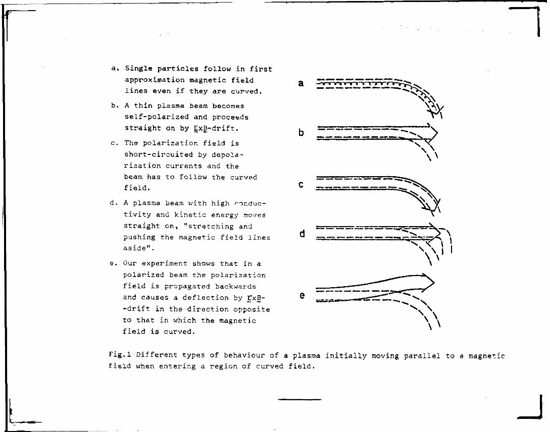
ways when entering a curved field. According to fig. 1, a-d,
we can distinguish four main cases:
a) If the matter in the beam is sufficiently thin, i.e. the
Debye length is greater than the width of the beam, it may
be treated as single particles, The guiding center approxima-
tion or an exact method may be used, depending on the parame-
ters. In zero order approximation the particles follow the
curved field lines. In ?:irst approximation grad B- and iner-
tia drifts give rise to additional drift motions perpendi-
cular to the plane of the figure.
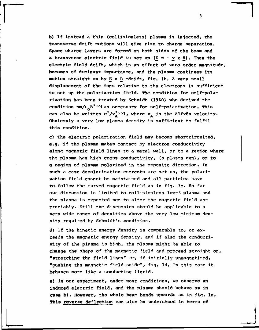
rb) If instead a thin (collisionless) plasma is injected, the
transverse drift motions will give rise to charge separation.
Space charge layers are formed on both sides of the beam and
a transverse electric field is set up (E = - v x B ) . Then the
electric field drift, which is an effect of zero order magnitude,
becomes of dominant importance, and the plasma continues its
motion straight on by E x B -drift, fig. lb. A very small
displacement of the ions relative to the electrons is sufficient
to set up the polarization field. The condition for self-pola-
rization has been treated by Schmidt (1960) who derived the
condition nm/e B 2»las necessary for self-polarization. This
can also be written C 2 / V ^ > > 1 , where vft is the Alfvén velocity.
Obviously a very low plasma density is sufficient to fulfil
this condition.
c) The electric polarization field may become shortcircuited,
e.g. if the plasma makes contact by electron conductivity
along magnetic field lines to a metal wall, or to a region where
the plasma has high cross-conductivity, (a plasma gun), or to
a region of plasma polarized in the opposite direction. In
such a case depolarization currents are set up, the polari-
zation field cannot be maintained and all particles have
to follow the curved magnetic field as in fig. lc. So far
our discussion is limited to collisionless low-6 plasma and
the plasma is expected not to alter the magnetic field ap-
preciably. Still the discussion should be applicable to a
very wide range of densities above the very low minimum den-
sity required by Schmidt's condition.
d) If the kinetic energy density is comparable to, or ex-
ceeds the magnetic energy density, and if also the conducti-
vity of the plasma is high, the plasma might be able to
change the shape of the magnetic field and proceed straight on,
"stretching the field lines" or, if initially unmagnetined,
"pushing the magnetic field aside", fig. Id. In this case it
behaves more like a conducting liquid.
e) In our experiment, under most conditions, we observe an
Induced electric field, and the plasma should behave as in
case b ) . However, the whole beam bends upwards as in fig. le.
This reverse deflection can also be understood in term3 of
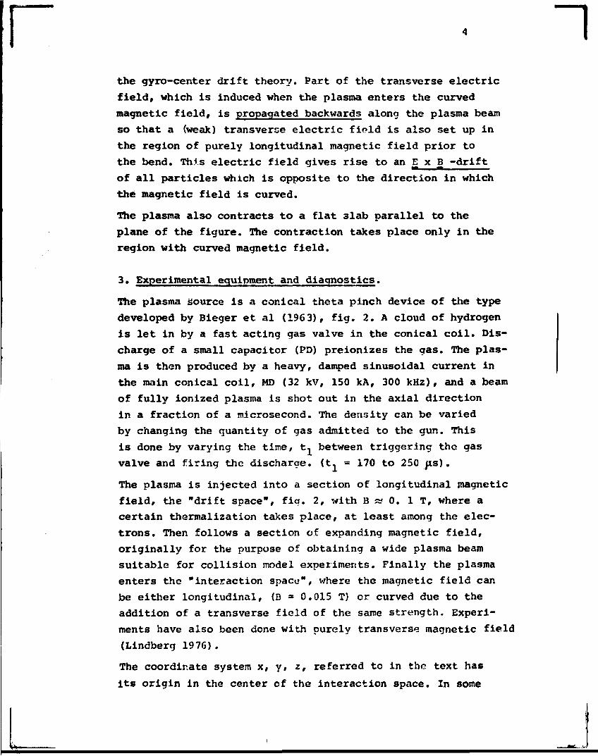
~lthe gyro-center drift theory. Part of the transverse electric
field, which is induced when the plasma enters the curved
magnetic field, is propagated backwards along the plasma beam
so that a (weak) transverse electric field is also set up in
the region of purely longitudinal magnetic field prior to
the bend. Thi.s electric field gives rise to an E x B -drift
of all particles which is opposite to the direction in which
the magnetic field is curved.
The plasma also contracts to a flat 3lab parallel to the
plane of the figure. The contraction takes place only in the
region with curved magnetic field.
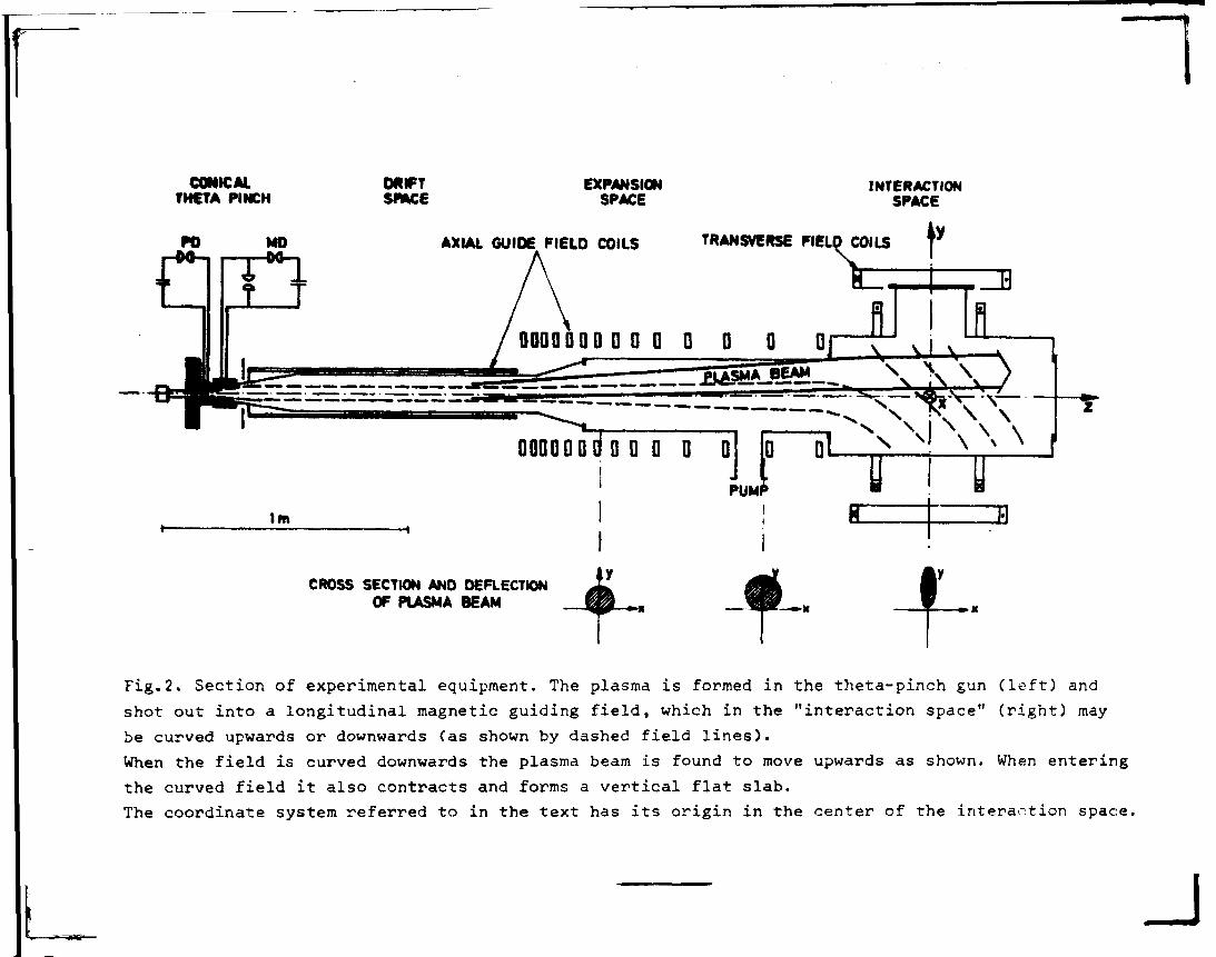
3. Experimental equipment and diagnostics.
The plasma Source is a conical theta pinch device of the type
developed by Bieger et al (1963), fig. 2. A cloud of hydrogen
is let in by a fast acting gas valve in the conical coil. Dis-
charge of a small capacitor (PD) preionizes the gas. The plas-
ma is then produced by a heavy, damped sinusoidal current in
the main conical coil, MD (32 kV, 150 kA, 300 kHz), and a beam
of fully ionized plasma is shot out in the axial direction
in a fraction of a microsecond. The density can be varied
by changing the quantity of gas admitted to the gun. This
is done by varying the time/ t, between triggering the gas
valve and firing the discharge. (t1 = 170 to 250 /is).
The plasma is injected into a section of longitudinal magnetic
field, the "drift space", fig. 2, with B « 0. IT, where a
certain thermalization takes place, at least among the elec-
trons. Then follows a section of expanding magnetic field,
originally for the purpose of obtaining a wide plasma beam
suitable for collision model experiments. Finally the plasma
enters the "interaction space", where the magnetic field can
be either longitudinal, (B * 0.015 T) or curved due to the
addition of a transverse field of the same strength. Experi-
ments have also been done with purely transverse magnetic field
(Lindberg 1976).
The coordinate system x, y, z, referred to in the text has
its origin in the center of the interaction space. In some
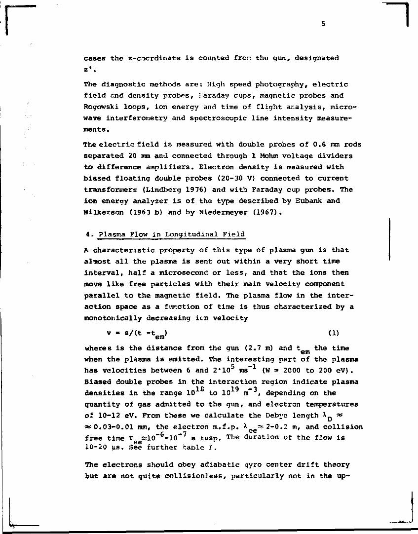
«Luaaaa> ~lcases the z-cocrdinate is counted fror. the gun, designated
zf.
The diagnostic methods are: High speed photography, electric
field end density probes, 1 araday cups, magnetic probes and
Rogowski loops, ion energy and time of flight analysis, micro-
wave interferometry and spectroscopic line intensity measure-
ments.
The electric field is measured with double probes of 0.6 mm rods
separated 20 ram and connected through 1 Mohm voltage dividers
to difference amplifiers. Electron density is measured with
biased floating double probes (20-30 V) connected to current
transformers (Lindberg 1976) and with Faraday cup probes. The
ion energy analyzer is of the type described by Eubank and
Wilkerson (1963 b) and by Niedermeyer (1967).
4. Plasma Flow in Longitudinal Field
A characteristic property of this type of plasma gun is that
almost all the plasma is sent out within a very short time
interval, half a microsecond or less, and that the ions then
move like free particles with their main velocity component
parallel to the magnetic field. The plasma flow in the inter-
action space as a function of time is thus characterized by a
monotonically decreasing icn velocity
v = s/(t -tem) (1)
wheres is the distance from the gun (2.7 m) and t „ the timeem
when the plasma is emitted. The interesting part of the plasma
has velocities between 6 and 2*105 ms"1 (W = 2000 to 200 eV).
Biased double probes in the interaction region indicate plasma
densities in the range 10 to 10 m , depending on the
quantity of gas admitted to the gun, and electron temperatures
of 10-12 eV. From these we calculate the Debyo length A as
«0.03-0.01 mm, the electron m.f.p. A a»2-0.2 m, and collision/- -t e e
free time T «rl0 -10 s resp. The duration of the flow isee
10-20 ys. See further table I.
The electrons should obey adiabatic gyro center drift theory
but are not quite collisionless, particularly not in the up-
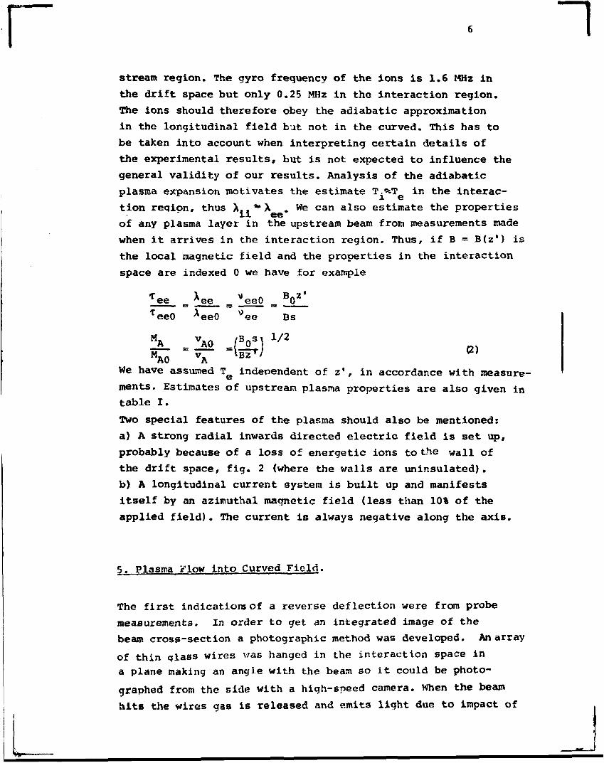
~lstream region. The gyro frequency of the ions is 1.6 MHz in
the drift space but only 0.25 MHz in the interaction region.
The ions should therefore obey the adiabatic approximation
in the longitudinal field but not in the curved. This has to
be taken into account when interpreting certain details of
the experimental results, but is not expected to influence the
general validity of our results. Analysis of the adiabatic
plasma expansion motivates the estimate T.«*T- in the interac-
tion reqipn, thus X,. ~ A .We can also estimate the properties
of any plasma layer in the upstream beam from measurements made
when it arrives in the interaction region. Thus, if B = B(z') is
the local magnetic field and the properties in the interaction
space are indexed 0 we have for example
ee _ ̂ ee _ eeO _ 0
eeO eeO ee Bs
MA VA0 /Vl V 2
M_n V- »BZ '
We have assumed T e independent of z', in accordance with measure-
ments. Estimates of upstream plasma properties are also given in
table I.
Two special features of the plasma should also be mentioned:
a) A strong radial inwards directed electric field is set up,
probably because of a loss of energetic ions to the wall of
the drift space, fig. 2 (where the walls are uninsulated).
b) A longitudinal current system is built up and manifests
itself by an azimuthal magnetic field (less than 10% of the
applied field). The current is always negative along the axis.
5. Plasma Flow into Curved Field.
The first indications of a reverse deflection were from probe
measurements. In order to get an integrated image of the
beam cross-section a photographic method was developed. An array
of thin qlass wires v;as hanged in the interaction space in
a plane making an angle with the beam so it could be photo-
graphed from the side with a high-speed camera. When the beam
hit» the wires gas is released and emit3 light due to impact of
r ~ielectrons from the plasma. The time response is fairly quick,
of the order of a few microseconds. The method gives a rough
image of the position of the plasma but can of course hardly
be relied on for quantitative measurements. A pair of typi-
cal pictures for longitudinal and curved magnetic field are
shown in fig. 3.
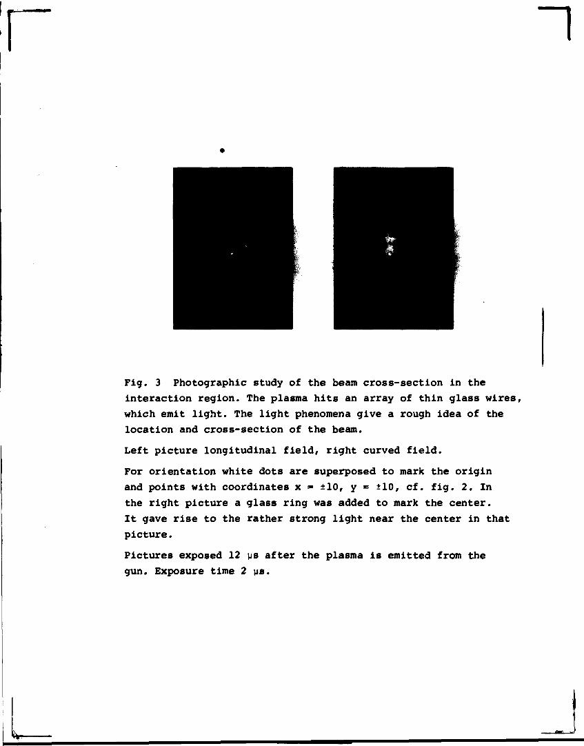
We note the circular cross-section of the original plasma
beam in longitudinal magnetic field. When the transverse
field component is added in the interaction region the beam
contracts sideways to a flat slab nearly parallel or slight-
ly tilted to the transverse magnetic field. The beam also
becomes strongly deflected upwards. If the applied field is
instead curved upwards, the beam bends downwards, always in
the direction opposite to that into which the applied mag"
netic field is curved.
The photographic method was also used upstream. Thus an
array of glass wires placed just where the ir.agnetic field be-
gins to curve {^ig, 2} , shows practically no contraction of
the beam, but tho vertical deflection is fully developed.
When the glass wires were placed further upstream, where thu
drift space joins the expansion space, a vertical displace-
ment was observed even there. We conclude that, the reverse
defle .tion takes place fa upstream and grows along the
longitudinal magnetic field, but that the rldewav? contrac-
tion takes place locally in the region with curved field.
A careful mapping of plasma density, electric field ard po-
tential as well as magnetic field changes hes been made by
extensive probe measurements, particularly in tlvs plane z ~
•» 0, but also upstream, in the transition region with curved
magnetic field (Lindberg and Kristoferson 1972). The elec-
tric field probes are, because of their very high impedance
{1 M SI), very sensitive, and react even to a much thinner17 —"\
plasma (n< 10 m ) than can bo detected with the floating
double probes used for density measurements. Therefore the
arrival of tho plasma in the interaction region and its very
quick deflection is detected first by the E-prcbos and some-
what later by the density probes. The deflection is very
clearly demonstrated by means of combined E- and density pro-
bes placed near tne upper wall at z = 0 and T. - -70 cm. Pro-
rbes at the lower wall indicate no plasma.
The tine sequence of the onset of these probe signals is
interesting: First the E -field is observed in the center (The
origin, fig. 2 ) . One microsecond later the E-probe at y = 16,
z = 0 (cm) also shows an E -field. The density probe in the
center begins to indicate plasma 2 \is after the E-probe f
and the density probe at y = 16, z = 0 still 1 us later. The
density probe at y = 16, z = -70 indicates plasma already
1 ps after the E-probe at the origin.
We conclude that as soon as the plasma enters the region with
transverse field component an electric field is induced, this
field propagates backwards, with a velocity much higher than
the flow velocity, into the region with longitudinal magnetic
field, and there gives rise to the upwards JlxB-drift of the
plasma.
Direct measurement of the backwards propagating electric field
in the upstream region with longitudinal magnetic field is
obscured by the presence of a strong negative radial electric
field originating fr^m the gunf mentioned in section 4.
Particularly it is impossible to observe the onset of the
backwards propagated field. However, the radial field decays
rapidly and then a difference is seen between the two sides
of the beam, indicating a superposed transverse field of the
order 20 - 30 % of the field induced at z = 0.
The duration of the flow in the center is shorter than it would
be in case of longitudinal field, but to the upper probe it
is of comparable length. Obviously the beam stays deflected
towards the upper wall during the whole time of flow. This
is interesting because one might expect a flip-flop instability
of the beam, i.e. if it were completely deflected no plasma
would enter the region with transverse magnetic field, the
transverse electric field would then vanish and the beam go
straight on, produce an E-field and again become deflected etc.
No such relaxation oscillations of the beam have been observed.
Obviously it is sufficient that a thin fraction of the beam
enters the region with curved field to produce an E_-field
that keeps the beam steadily deflected.
rBoth the observation that the reverse deflection begins very
17 -3early, as soon as a very thin plasma (n < lu m ) induces an
electric field, and the steadiness of the deflection just
discussed, indicate that the deflection mechanism operates very
efficiently already at very low plasma densities. A sufficient
condition may be that the Debye length should be much smaller
than the beam width (This is necessary for self-polarization)-
When discussing the backwards propagation of the electric
field the question arises whether the plasma is sup.r-Alfvénic
or not. Certainly the experiments cover a range of densities
for which the Alfvén - Mach number is both higher and lower
than one {in the interaction region as well as upstream accor-
ding to eq. (2)), and the reverse deflection is observed in all
cases. However, this statement refers only to the dense central
part of the beam and it could always be argued that in the ini-
tial flow, as well as in the boundaries of the flow, the den-
sity is so low that the Alfvén velocity always exceeds the
flow velocity, and that Alfvén waves might propagate the elec-
tric field upstream.
We leave this question having found that a backwards flow of
energetic electrons occurs on that side of the plasma beam which
is polarized to negative potential. This electron flow sets up
a space charge wave which propagates the transverse electric
field upstream.
6. Backwards Flow of Energetic Electrons.
The transverse electric field propagates upstream due to electron
space charge displacements. This is most convincingly shown by
direction sensitive Faraday-cup measurements in the edges of the
upstream beam. These indicate a backflow of energetic electrons
in that side of the beam which is connected to the region which ii
polarized to a negative potential in the curved magnetic field.
For continuity reasons an opposite electron flow must exist in tht
positive side of the beam, but it cannot be directly measured
because it is obscured by the plasma flow from the gun. The cur-
rent greatly exceeds that required to set up the polarization
charges upstream. This will be further discussed in section 9.
10
The Faraday cup probe consists of an outer electrode in the form of
a short'cylinder (diam. 1.5 mm) with an entrance hole (diam. 0.8 mm)
through which particles can zaach an inner electrode. A bias vol-
tage can be applied between the electrodes and the current is
measured by means of a transformer, which isolates the circuit from
ground. The probes are used with the hole pointing either upstream
or downstream in the region with longitudinal field so that partic-
ip ' les can enter unimpeded by the magnetic field. This is especially
important for the electrons, which are tightly confined by the
magnetic field.
Such probes have been placed in the edge of the beam on both si-
des at two upstream positions, z = -130 and -70 cm. The ions can
hit the probe only on its upstream side, and an ion wake is for-
med behind it. Electrons should in principle be able to reach
the probe equally well from the downstream plasma, but they build
up a negative space charge in the wake which greatly reduces the
electron flow to the downstream side of the probe.
From the oscillograms obtained when the orobes are pointing up-
stream the plasma density and electron temperature are evaluated.
£ In the case of curved magnetic field in the interaction region,
the density and temperature measurements at the upstream loca-
s tions do not change very much. The density is almost the same as
I in case of longitudinal magnetic field, but a small temperature
I increase is indicated in both sides of the beam, of the order
I 20-30%. This figure is uncertain because it is of the same roagni-
? tude as the inaccuracy of the measurement. However, spectroscopic
. measurements also indicate a temperature rise in the plasma when
• it is injected in a curved field.
• When the Faraday cup probes are pointing downstream certain
t electron currents enter Uhf» probe from the downstream direction.II With curved magnetic field these are much higher than for longi-|j
I tudinal field, particularly in the negative side of the beam.
The question arises whether this can be explained as an effect of
• the temperature increase observed for curved field, or if these
electrons are non-thermal. An extensive analysis of the probe
j theory (Lindberg and Kristoferson 1972) shows that an increase
of the electron temperature could result in an increase of the
backwards electron current, but only in proportion to T e or
r ii
3
at most to 1^2. Further, the same increase should be obser-
ved on both sides of the beam.Since the observed increase
is very much higher but occurs only in the negative side
of the beair. (at z = -70 cm) we definitely conclude that
the strong backwards flow of electrons is due to a popula-
tion of non-thermal electrons having a hit|h directed velo-
city in tho backwards direction, superposed on the thermal
electron population. Since these electrons overcome the
space charge harrier in the v/ake, we can front typical mea-
surements estimate that they must have a directed energy
of at last 50 eV. The corresponding velocity, 4«106ms~l,
should characterize the backwards propagation of the elec-
tric field. The density of these energetic electrons can be
estimated to n = 5*10^^m~3 i.e. some percent of the plasma
density. The non-thermal electrons are stopped x*hen the probe
is biased negative. Their velocity distribution may be de-
scribed as a displaced Maxwell distribution, with a tempera-
ture of the same order as for the main electron population.
This indicates that these electrons are accelerated by an
electric field in the region with curved field, presunably by
electric field components parallel to the magnetic field.
The probe further upstream, at z = -130, shows a backflow of
energetic electrons on both sides of :he beam. This can be
understood as a consequerce of the potential distribution
in the beam, which will be discussed in the next section,
and which is sketched at the bottom of fig. 4. The poten-
tial distribution of the plasma adjusts itself so that the
upstream plasma is connected by equipotential lines to the
negative side of the downstream plasma. It is consequently
possible for backwards moving electrons to drift along equi-
potential lines and reach both sides of the far upstream beam.
This does not imply that the current on the positive side flows
in the downstream direction, because the current is the net ef-
fect of the motion of all charged particles, ions, thermal e-
lectrons and energetic electrons, and on the positive side the
downstream flow of thermal electrons certainly dominate*.
7. Mechanism of the Reverse Deflection.
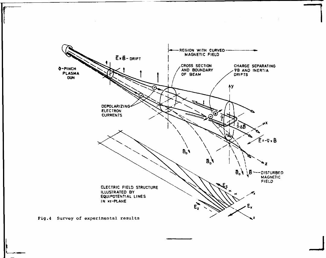
Fig. 4 is a perspective sketch summarizing the main features
of the plasma flow. The plasma from the gun has originally a
circular cross-section. When entering the curved field grad
B - drift (and curvature drift) gives rise to charge separa-
tion and the beam becomes polarized with a transverse elec-
~ !
r 12
trie fielct E = - v x B, and a potential difference is deve-
loped across the beam. On the negative side electrons are
streaming backwards to the upstream region and on the positive
side electrons are attracted from the upstream region. In this
way part of the polarization field is propagated upstream,
there giving rise to an E x B - drift of the whole plasma
beam upwards. The current system that arises carries orders
of magnitude higher currents than needed to set up the polari-
zation charges. It can be described as a transverse polari-
zing current in the region with transverse magnetic field
component and depolarizing currents flowing upstream along
the beam. Due to the collisionless and anisotropic character
of the plasma the current system is only partially closed
bycurrents across the beam, but presumably mostly by currents ir
the gun region, where a collision dominated plasma is likely to
remain. The magnitude of the current depends on the conductance
of the closed circuit as a whole. This will be further discussec
in section 9 .
In case of the highest plasma densities used these currents
give rise to a slight reduction AB of the transverse compo-
nent of the magnetic field.
The backwards streaming electrons contain a population of
energetic non-thermal run-away electrons, indicating the
existence of electric field components parallel to the mag-
netic field. Such components are necessary to make the elec-
tric field almost curl-free.
The potential distribution in a horizontal plane y = 0 is
sketched at the bottom of fig 4. It is not symmetric with
respect to the yz-plane, but adjusts itself so that the up-
stream plasma attains approximately the same potential as the
negative side in the curved magnetic field.
This can be understood as a consequence of the different mag-
nitudes of particle energies. For the electrons the thermal
energy dominates, and even this is quite small, about 10 eV.
The electrons are not quite collisionless, but collide rather
infrequently in the region of curved magnetic field and have
not energy enough to enter a region with more negative poten-
tial than corresponds to their kinetic energy. The ions, on
~1
13
the contrary, have high energies, 300-1000 eV, mainly as
directed energy, and are therefore able to penetrate and
cross a region with correspondingly high positive potential.
When doing so their velocity goes down during the passage.
This ha? been verified by means of the ion analyzer. Ions of
a certain energy having passed the region with positive poten-
tial have a longer time of flight.
8. Å theoretical Approach
In the experiment the plasma moves from one region having a
priori no potential difference across the plasma (the upstream
region), into another region where a great potential difference
is set up across the plasma due to the induced electric field.
The flow has a pronounced transient character particularly in
the beginning. Very socn the transverse electric field propa-
gates backwards and then the character of the flow changes
towards a quasi-stationary flow along equipotential surfaces,
but such a state is certainly never reached. The existence
of electric field components parallel to the magnetic field is
indicated by the occurrence of energetic, non-thermal electrons.
It is obvious that such a flow cannot be understood in terms of
elementary hydromagnetic theory, e.g. by treating the plasma
as a fluid with infinite conductivity. We meet the same diffi-
culty if we apply the guiding center drift approximation theory
assuming no electric fields parallel to the magnetic field, in
which case the particles should drift along equipotential sur-
faces.
However, if we allow for electric field components parallel to
the magnetic field the guiding center theory should, because
of the nearly collisionless character of the plasma, be well
suited to describe plasma flov; into a curved magnetic field.
(We consider here a general case f when the ions also obey gui-
dinq center theory). Schmidt (1960) has made such a study,
using a cylindrical coordinate system. Since we are studying
an almost linear motion we prefer rectangular coordinates.
For each kind of particle the motion of the guiding center
~l
14
transverse to the magnetic field obeys the drift equation
' u = - -ir B x (f 4 f + f.)"^ qB2 "" -e -m -i
and the motion parallel to the magnetic field is guided by
fi "tie *
~l
(Alfvén 1940, Alfvén and Fälthamroar 1963)
Eq. (3) and (4) can be rewritten:
mv„ = £ S | 4 * B x VB • -JL B x j3tt"•*•" B2 2qB3 qB2 " d t
(5)
2m • qE- - — — (VB)B (6)dt 23
The three terms in eq.(5)are the electric drift, the grad B-drift
and the inertia drift resp.
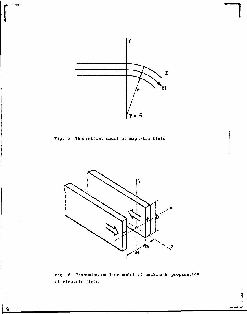
We assume a magnetic field model, which for z > 0 has circular
field lines with B = BoR/r (as if due to a line current at
y s -R), and for z < 0 straight field lines^iq.5 . Such a field
has div B = 0 but curl B i O, which means that a space current
density has to be assumed for z < 0. Ever, if such an assump-
tion seems artificial, it is not in conflict with the applica-
bility of the guiding center theory. Alternatively we could
assume that the particles start their motion in the plane
z = 0 with the same velocities as they have in the homogeneous
longitudinal magnetic field prior to the bend.
We are interested in drift motion approximately along a straight
line with almost constant velocity and want to find the condi-
tions for it. This means the case when the inertia drift is
small. It is then no meaning to split the inertia drift term
into curvature drift and polarization drift x ) , two terms that
would almost cancel each other.
x).In this context we would like» to point out that the term "cen-trifugal drift" often is misleading (because it gives associa-tions to curved motion)and should be abandoned. Consider e.g.particles performing drift motions along a straight line in acurved magnetic field. They are subject to a strong "centrifu-gal drift" even when the motion is linearI The term "curvaturedrift" is more adequate.
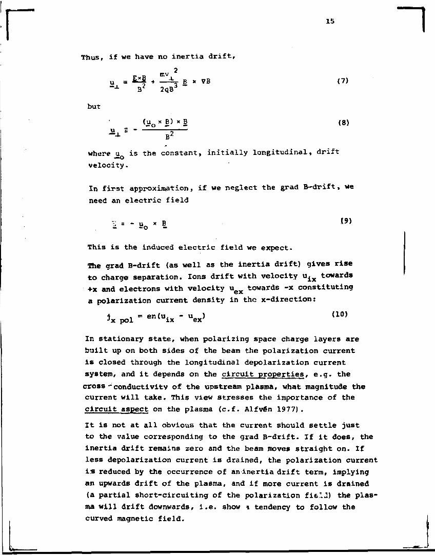
r 15 ~iThus, if we have no inertia drift.
IP V
u a fcfi • -Ii- B x 7B (7)
but
(u x B) x B (8)U 2 -
— O «- —
B2
where u is the constant, initially longitudinal, drift—•o
velocity.
In first approximation, if we neglect the grad B-drift, we
need an electric field
i = " uo x 5.19)
This is the induced electric field we expect.
The grad B-drift (as well as the inertia drift) gives rise
to charge separation. Ions drift with velocity uix towards
+x and electrons with velocity u towards -x constituting
a polarization current density in the x-direction:
*x pol - en(uix - uex> (10)
In stationary state, when polarizing space charge layers are
built up on both sides of the beam the polarization current
is closed through the longitudinal depolarization current
system, and it depends on the circuit properties, e.g. the
cross - conductivity of the upstream plasma, what magnitude the
current will take. This view stresses the importance of the
circuit aspect on the plasma (c.f. Alfvén 1977).
It is not at all obvious that the current should settle just
to the value corresponding to the grad B-drift. If it does, the
inertia drift remains zero and the beam moves straight on. If
less depolarization current is drained, the polarization current
is reduced by the occurrence of an inertia drift term, implying
an upwards drift of the plasma, and if more current is drained
(a partial short-circuiting of the polarization fifel.2) the plas-
ma will drift downwards, i.e. show * tendency to follow the
curved magnetic field.
16
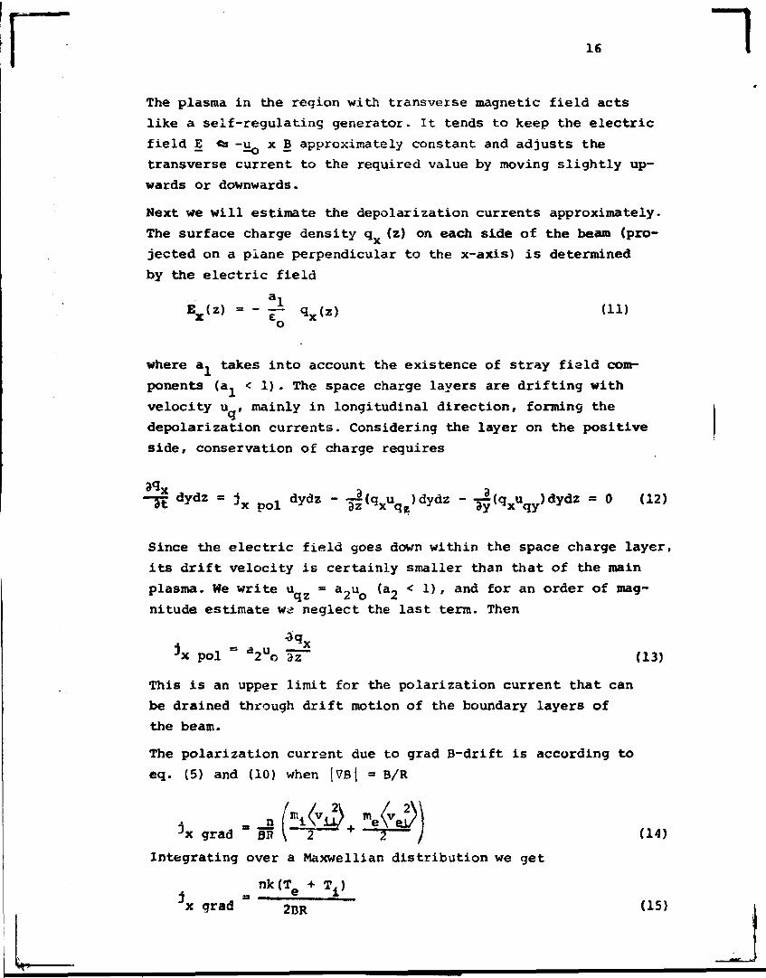
The plasma in the region with transveise magnetic field acts
like a self-regulating generator. It tends to keep the electric
field E «s -u^ x B approximately constant and adjusts the
transverse current to the required value by moving slightly up-
wards or downwards.
Next we will estimate the depolarization currents approximately.
The surface charge density q (z) on each side of the beam (pro-
jected on a plane perpendicular to the x-axis) is determined
by the electric field
E (z) = - -i q (Z) (11)x eQ x
where a, takes into account the existence of stray fiald com-
ponents (a. < 1). The space charge layers are drifting with
velocity u , mainly in longitudinal direction, forming the
depolarization currents. Considering the layer on the positive
side, conservation of charge requires
"TÉ dydz = jx pol dydz - 3i(^xuqe)dydz " -ä| (Vqy ) d y d 2 = ° (12)
Since the electric field goes down within the space charge layer,
its drift velocity is certainly smaller than that of the main
plasma. We write u = a~u (a- < 1) , and for an order of mag-
nitude estimate wa neglect the last term. Then
3x pol ° a2uo ~ (13)
This is an upper limit for the polarization current that can
be drained through drift motion of the boundary layers of
the beam.
The polarization current due to grad B-drift is according to
eq. (5) and (10) when |7B| » B/R
jx grad " BP \~2 ' + ~ r / (14)Integrating over a Maxwellian distribution we get
nk(T + T.)j ex grad 2BR
r 17
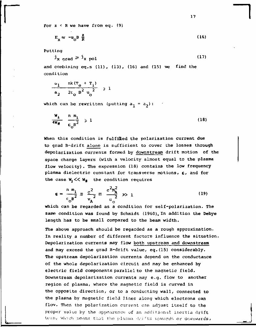
For z < R we have from eq. (9)
Ex*-uoB§ (16)
Puttingjx grad ̂ jx pol {17)
and combining eq.s (11), (13), (16) and (15) we find the
condi tion
u 1 nk(Te + T±)1
a_ 2e B 2 u 22 o o
whichich can be rewritten (putting a, = a_):
W. n m.
When this condition is fulfilled the polarization current due
to grad B-drift alone is sufficient to cover the losses through
depolarization currents formed by downstream drift motion of the
space charge layers (with a velocity almost equal to the plasma
flow velocity). The expression (18) contains the low frequency
plasma dielectric constant for transverse motions, c, and for
the case W j « WB the condition requires
n m. 2 c2M2
(19)
which can be regarded as a condition for self-polarization. The
same condition was found by Schmidt (1960). In addition the Debye
length has to be small compared to the beam width.
The above approach should be regarded as a rough approximation.
In reality a number of different factors influence the situation.
Depolarization currents may flow both upstream and downstream
and may exceed the grad B-drift value, eq.(15) considerably.
The upstream depolarization currents depend on the conductance
of the whole depolarization circuit and may be enhanced by
electric field components parallel to the magnetic field.
Downstream depolarization currents may e.g. flow to another
region of plasma, where the magnetic field is curved in
the opposite direction, or to a conducting wall, connected to
the plasma by magnetic field lines along which electrons can
flow. Then the polarization current c m adjust itself to the
proper value by the appearoncr; of an addition.;»! inertia drift
tiriuri, winch moans that: tho plasma -lrj fts upv/iirdr; or downwards,
18
and in the most extreme cases when the field is short circuited,
follows the curved field.
9. The Depolarization Circuit.
. In the experiment the Alfvén-Mach number MÄ is about2one or maybe two. Since M. is equal to the ratio of kinetic
to magnetic energy density in the plasma this means that a
deformation of the magnetic field (such as discusped in sec-
tion 2 d) is energetically possible. However the plasma must
also be able to carry the currents necessary to change the
magnetic field. Since no remarkable field variations are ob-
served, the currents are obviously limited in some way.
In the previous section we have just discussed the "generator-
action" in the rogion with curved magnetic field, and the
magnitude of the depolarization currents that can be trans-
ported due to drift notion of the space charge layers. We
will now discuss the passive, upstream part of the circuit.
In the upstream region with purely longitudinal magnetic field
the current system consists of longitudinal currents along
the sides of the beam and transverse "leakage" currents across
the beam and, in the experiment also transverse current in the
gun region. Judging from the existence of a transverse electric
field upstream (manifested by the reverse deflection of the far
upstream beam) the transverse impedance is quite high.
Considering a general case, e.g. a long plasma beam in a
longitudinal magnetic field in free space, entering a curved
field, it would be interesting to estimate how far backwards
the transverse electric field could propagate. It is not ob-
vious at all that the elctron mean free path should be the
relevant length. Although we realize that the concepts of
conductivity may be of limited applicability, it is instruc-
tive to study the case when the plasma can be described by
two conductivites a» and o. , parallel and perpendicular to
the magnetic field. Then the problem is analogous to propa-
gation of a wave on a lossy transmission line, which obeys
the telegraph equation (see e.g. Hallen 1963 or Landau and
r 19
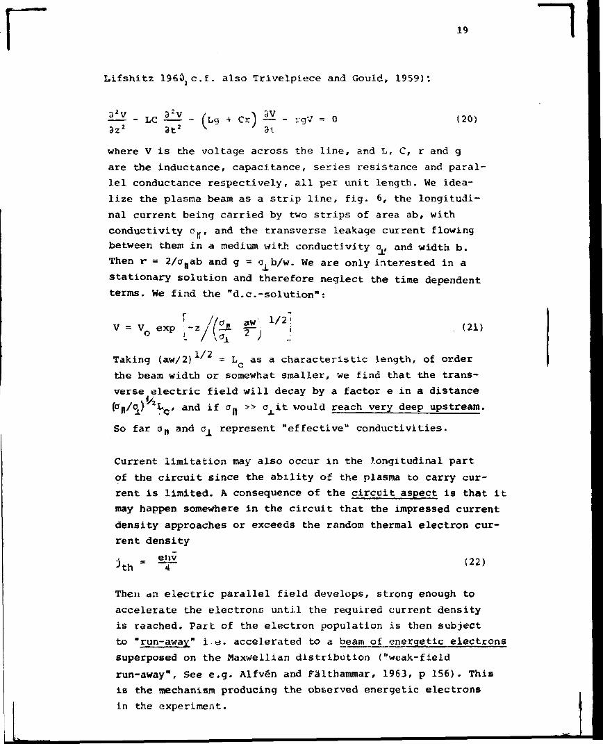
Lifshitz 196ÖjC.f. also Trivelpiece and Gould, 1959):
32V
3zz 3t+ Cr —
31- rgV = 0 (20)
where V is the voltage across the line, and L, C, r and g
are the inductance, capacitance, series resistance and paral-
lel conductance respectively, all per unit length. We idea-
lize the plasma beam as a strip line, fig. 6, the longitudi-
nal current being carried by two strips of area ab, with
conductivity o(f, and the transversa leakage current flowing
between them in a medium with conductivity a, and width b.
Then r = 2/onab and g = o^b/w. We are only interested in a
stationary solution and therefore neglect the time dependent
terms. We find the nd.c.-solution":
V = V expo c |
z. -a. 2 (21)7 W 2 >
Taking (aw/2) ' = L as a characteristic length, of order
the beam width or somewhat smaller, we find that the trans-
verse electric field will decay by a factor e in a distance
(0|,/<̂ ) 2 * w and if a» >> o it would reach very deep upstream.
So far an and o, represent "effective" conductivities.
Current limitation may also occur in the longitudinal part
of the circuit since the ability of the plasma to carry cur-
rent is limited. A consequence of the circuit aspect is that it
may happen somewhere in the circuit that the impressed current
density approaches or exceeds the random thermal electron cur-
rent density
jtheiw4
[22)
Then an electric parallel field develops, strong enough to
accelerate the electrons until the required current density
is reached. Part of the electron population is then subject
to "run-away" i.e. accelerated to a beam of energetic electrons
superposed on the Maxwellian distribution ("weak-field
run-away", See e.g. Alfvén and Falthammar, 1963, p 156). This
is the mechanism producing the observed energetic electrons
in the experiment.
r 20 1Another quantity which may be of importance for the backwards
propagation of the electric field is the electron temperature.
We have previously regarded the electron thermal velocity
being higher than the flow velocity as a necessary condition
for the backwards propagation. Considering the ability of
the parallel electric field to accelerate electrons and even
create a beair of fast electrons through the run-away pheno-
menon, the original thermal velocity in the beam may be of less
importance or of no importance at all. The run-away electrons
alone may propagate the field. They have much higher velocity
than the mean thermal electron velocity and, even more im-
portant, they have very much longer mean free paths. This
increases as the square of the electron energy (which is the
cause of the run-away phenomenon). Due to the run-away elec-
trons the effective parallel conductivity increases, while
their contribution to the transverse conductivity is extreme-
ly small because of their large Hall-parameter. The effective
transverse conductivity should therefore remain determined
by the main electron population. Our discussion so far app-
lies to the negative side of the plasma beam, in which
the run-away electrons are expelled upstream.
In the positive side of the beam the current density required
to fulfil the current cor.tinuity condition for the depolari-
zation circuit may be carried by a slow motion of the whole
electron population, but it is very likely that the run-
away phenomenon could play a role even there. It might even
be more likely in the positive side because the potential
difference between the upstream and downstream plasma is
much higherthere than in the negative side (fig. 4 ) . It should
start at a point where the parallel electric field is maximum,
presumably near the region with curved field. When it starts
the parallel electric field strength would drop locally
there, and also in the adjacent (downstream) region into
which the electrons are shot. If the circuit characteristic
is such that it tends to keep the total voltage constant,
the electric field in the adjacent upstream region should
increase, starting the run-away process there. We might get
a kind of "run-away-wavc" propagating upstream, or a "run-
away break-down" process in the r>3isma, in a sense similar
r 21
to the break-down in a ge.s. A rarefaction electron wave should
proceeds upstream, in a way similar to the motion of holes in a
semiconductor.
10. The Contraction of the Beam, and the Beam '.fidth
The contraction of a plasma bean moving in a purely transverse
magnetic field of increasing strength can, according to Baker
and Hammel (1962, 1965), Demidenko et al (1966, 1969, 1971)
and Karlson (1973) be understood in terras of the guiding cen-
ter theory, taking into account the curl-free character of the
electric field. Also in our experiment comparison of simultaneous
measurements with magnetic and electric probes indicate that curl
E is small compared with the spatial derivative of the induced
Ex~field. This implies that E - and E -components must also
exist, which give rise to an inwards E x B -drift. .
The collisionless character of the ion motion implies conser-
vation of energy and has the consequence that the maximum po-
tential difference that can develop across the beam cannot ex-
ceed a value corresponding to the actual ion energy, eU :
AU = w <E > < 0 (23)
where w is the beam width, eUQ = m.u2/2 and <E > = u B .
Thus the beam width is limited to
i 2 4 )
which happens to be half the gyro radius an ion would get in
the field B if all its energy were gyration energy. For u o =
* 3*10 s i B y == 15 mT we find w ^ 10 cm and this is approxi-
mately the width observed.
It is interesting to note that the beam width is determined
by the maximum ion energy, and not by the initial beam width.
One might speculate what would happen with an initially very
wide beair, It might split up in a number of beams when ente-
ring the region with transverse magnetic field. Such a split-
ting has been observed in the experiments by Marcovic and
Scott (1971).
r ~i11. Comparison with Other Experiments.
Contraction of a plasma bean me vine, in a rmroly transverse mag-
netic field has been observed and studied experimentally and theo-
retically in a number of papers e.g. by Baker (1962), Baker and
Hananel (1962, 1965), liamrnel and Baker (1966), Derr-idenko et al.
(1966, 1969, 1072), Khiznyak et al. (1965), Barney (1969), Mar-
coviC and Scott (1971) and Karlson (1973). Injection of plasma
into curved field has been studied by Eubank and Wilkerson (1961,
1963 a ) . Colonies and Veron (1969), Tanaka et al. (1972), Ejiroa
et al. (1974) and Komori et al. (1977). In most of these expe-
riments the plasma is depolarized by strong currents either to the
plasma source or between regions with opposite curvature of the
field. The reverse deflection taking place in the upstream longi-
tudinal field, first observed by Lindberg and Kristoferson (1971,
1972) is also clearly demonstrated in the experiments by Tanaka
et al,(1972) and Komori et al.(1977). The experiment of Komori
ét al. is of particular interest. It is done in a potassium plasma
with density three orders of magnitude lower than in our experiment
while the magnetic field is one order of magnitude stronger. Further
it allows different modes of operationj the plasma can either be
stationary with the plasma continously in contact with the plasma
source (which has high cross-conductivity), or prised, disconnected
from the source. In the latter case the reverse deflection is
strongly developed and most of the beam lost to the wall.
12. Conclusions.
Reverse deflection of a plasma beam moving from a region with
longitudinal magnetic field into a curved field seems to be a
phenomenon of fundamental character, which can be expected in a
wide parameter range in collisionless plasmas. The behaviour is
in principle understood in terms of the gyro center drift theory,
but a number of other aspects are important, particularly the
limited ability of the plasma to carry current, not only perpendi-
cular to the magnetic field, but also parallel. This leads to oc-
curence of electric field components parallel to the magnetic
field and acceleration of beams of energetic electrons through
the run-away process.
Because of the complexity of the problem we have discussed the
plasma behaviour only from quasi st«.s tionary points of view and
23
have completely nealected the role of wave propagarion and in-
stabilities. Such processes are certainly of qreat importance, e.g.
the various processes tending to separate electrons and ions are
likely to set up two-stream instabilities. In the experiment the
noisy character of all probe signals indicate oscillations and
instabilities.
In space physics the phenomenon could have far reaching conse-
quences. Often space plasma has morsor less beam character and
moves between regions with varying curvature of the magnetic
field, e.g. enterino the dipole field near a cosmical body or
a curved field at the boundary of a magnetosphere. Particularly
in cases where the field changes abruptly considerable electric
fields parallel to the magnetic field could arise. These could
accelerate beams of run-away electrons, both upstream, propaga-
ting the induced transverse electric field very far unstream, and
downstream. Possibly a phenomenon like energetic auroral rays
could be understood in this way.
Energetically the phenomenon is an example of an energy transfer
process in a plasma, which transfers kinetic energy from the ions
to the electrons and even can produce beams of energetic electrons.
In this sense it has a similarity with processes behind the cri-
tical ionization velocity phenomenon (Danielsson, 1973, Sherman
1973, Danielsson and Bränning 1975, Raadu 1975, 1977) and with pro-
cesses leading to the formation of electric double layers (Torvén
and Babie 1976, Block 1972, 1977).
The experiment demonstrates the complexity of plasma flow pheno-
mena and the need of intimate contact between exoerimental and
theoretical work.
Acknowledgement.
The author is indebted to prof.s C.-G. Fälthammar and E. Karlson
and to dr. M. Raadu for many stimulating discussions, to dr. L.
Kristoferson for years of fruitful cooperation, to mr. B. Johans-
son, J. Wistedt and R. östling for very valuable technical assis-
stance, and to mrs- E. Florman and K. Vikbladh for typing the manu-
script and mrs. K. Forsberg for making the drawings.
The project has been financed by the Swedish Atomic Research
Council.
~l
n 24 ~lReferences.
Alfvén, H.: 1940, On the Motion of a Charged Particle ir a
Magnetic Field, Ark. Mat. Astron. Fys., Swedish Academy
of Science, 27 A, Stockholm.
Alfvén, H.: 1968, Ann. de Géophys., 24, 1.
—————— *wAlfvén, H.: 1971, Science, 172, 991.
Alfvén, H.: 1977, Electric Currents in Cosmic Plasmas, Royal
Inst. of Technology, Stockholm 70, TRITA-EPP-77-14.
Alfvén, H. and Fälthammar, C-G.: 19G3, Cosmical Electrodynamics,
Clarendon Press, Oxford.
Alfvén, H. and Arrhenius, G.: 1976, Evolution of the Solar Sys-
tem, National Aeronautics and Space Administration, NASA
SP-345. U.S. Gov. Print. Office, Washington D.C.
Baker, D.A.: 1962, Los Alamos Sci. T>b. Res. Rep.
Baker, D.A. and Hemmel, J.E.: 1962, Phys. Rev. Lett. 8, 157.
Baker, D.A. and Hammel, J.E.: 1965, Phys. Fluids, 8, 713.ltT" ' " ^^
Barney, F.O.: 1969, Phys Fluids .L2, 2429.
Beckers, J.M.: 1963, Solar Phys. £, 367.
Bieger, W.,Gresser, H., Noll, P. and Tuczek, H.I.: 196 3, Z.
Naturforschung, 18a, 453.Block, L.P.: 1972, Cosmic Electrodynamics, 3, 349.
Block, L.P.: 1977, "A Double Layer Review", Royal Inst. of Tech-
nology, Stockholm 70, TRITA-EPP-77-16. Submitted to Astro-
phys. Space Sci.
Block, L.P. and Fälthammar, C-G.: 1976, Ann, de Oéophys., 32., 161
Brenning, N.: 1977, Electron Temperature Measurements In Low
Density Plasmas by Helium Spectroscopy, Royal Inst. of
Technology, Stockholm 70, TRITA-EPP-77-24.
Carlqvist, P.: 1969, Solar Phys, Tj 3 7 7*
Carlqvist, P.: 1972, Cosmic Electrodynamics, 3, 377
25
Colomès, J. And Vëron, D.: 1969, Phys. Fluids, j.2, 1717.
Danielsson, L. : 1973, Astrophys. Space Sei., 2jl, 459.
Danielsson, L. and Brenning, N.: 1975, Phys. Fluids, 18, 661.
Demidenko, I.I., Lomino, N.S., Padalha, V.O., Safronov, D.O. and
Sinelnikov, K.D.: 1966, J. Nticl. Energyf C. Plasma Physics,
&, 433.
Demidenko, I.I., Lomino, N.S., Padalka, V.O., Rutkevich, B.N.
and Sinelnikov, K.D.: 1969, Zh. Tekhn. Flz. 39, 27 (Sov.
Phys. - Techn. Phys. ̂ 4, 16, 1969).
Demidenko, I.I. , Lo.niro, N.S. and Padalka, V.O.: 1971, Zh. Tekhn.
Fiz. 41, 1392 (Sov. Phys. - Techn. Phys. 16, 1096, 1972).
Ejima, S., Marshall, T.C. and Schlesinger, S.P.: 1974, Phys.
Fluids, 17, 163.
Eubank, H.P. and Wilkerson, T.D.: 1961, Phys. Fluids, ̂ 1407.
Eubank, H.P. and Wilkerson, T.D.: 1963 a, Phys. Fluids, 6j 914.
Eubank, H.P. and Wilkerson, T.D.: 1963 b, Rev. Sei. Instr., 34,
12.
Fälthammar, C-d 1977, Interpretation cf Laboratory Experiments
of Interest to Space Physics. To be publ. in Rev. Geophys.
and Space Phys., Nov. 1977.
Hammel, J.E. and Baker, D.A.: 1966, Proc. Conf. on Plasma Phy-
sics and Controlled Nuclear Fusion Res. Culham 1965, IAEA
Vienna, 1966.
Hammel, J.E. and Kewish, R-W.: 1969, Plasma Stream Interactions
Through Polarization Electric Fields, Los Alamos Sei. Lab.
Res. Rep. LA 3994,
Hallen, E.: 1963, Electromagnetic Theoryf Chapman and Hall,
London.
Karlson, E.i 1973, Plasma Stream in an Inhomogeneous Transverse
Magnetic Field, Royal Inst. of Technology, Stockholm 70,
TRITA-EPP-73-08, Abbreviated version publ. in Proc. 6th
European Conf. on Controlled Fusion and Plasma Physics,
Moscow, 1973, p. 397«
~l
26
Khiznyak, N.A.: 1965, 2h. Tekhn. Fiz. 35, 847. (_Sov. Phys.-Techn.
Phys., 3£, 655, 1965).
Komori, A., Sato, N., Sugai, H. and Hatta, Y.: 1977, Plasma Phys.
IS, 233.
Kopp, R.A. and Kuperus, M.: 1968, Solar Phys. ̂ 212.
Landau, L.D. and Lifshitz, E.M.: 1960, Electrodynamics of
Continous Media, Pergamon Press,
Lindberg, L.: 1976, Irjection of Plasma into a Transverse Mag-
netic Field, Royal.Inst. of Technology, Stockholm 70,
TRITA-::PP-76-01.
Lindberg, L. and Kristoferson, ^.: 1971, Cosmic Electrodynamics,
2, 305.
Lindberg, L. and Kristoferson, L.: 1972, Reverse Defleebion and
Contraction of a Plasma Ream Entering a Curved Magnetic
Field, Royal Inst. of Technology, Stockholm 70, TRITA-EPP-
72-32.
Markovie, P.D. and Scott, F.R.: 1971, Phys. Fluids, 14. 1742.
Neugebauer, M. and Snyder, C.W.: 1966, J. deophys. Res., 71,
4469.
Niedermever, H.: 1967, Ein Elektrostatischer Analysator zur
Messung der Energie von Ionen und Elektronen aus heissen
,Plasmen. Garching Res. Rep. II 1/66.
Raadu, M.A.: 1975, Critical Ionizatlon Velocity and Electrosta-
tic Instabllitiep, Royal Inst. of Technology, Stockholm 70,
TRITA-EPP-75-28.
Raadu, M.A.: 1977, The Role of Electrostatic Instabilities in the
Critical Ionizatlon Velocity Mechanism, Royal Inst. of
Technology, Stockholm 70, TRITA-EPP-77-18. To be publ. in
Astrophys. Space Sei.
Schmidt, G.s 1960, Phys. Fluids, 961.
Shawhan, S.D., Fälthammar, C-G. and Block, L.P.: 1977, On the
Nature of Large Auroral Zone Electric Fields at One
Altitude, Royal Inst. of Technology, Stockholm 70, TRITA-
EPP-77-09. Also in University of Iowa, USA, Report 77-25.
r 21
Sherman, J.C.: 1973, Astrophys. Space Sci. 2Aj 487.
Tanaka, Y., Oya, K., Okuda, T., and Yamamoto, K.: 1972, J. Phys.
Soc. Japan, 3£, 510.
Torvén, S. and Babic, M.: 1975, Current Chopping Space Charge
Layers in a Low Pressure Arc Plasma, Proc. 12th Int. Conf.
on Phenomena in Ionized Gases, Eindhoven, ][, 124. (Eds.
J.G.A. Hölscher and D.C. Schram, North Holland/Elsevier
Trivelpiece, A.W. and Gould, R.W.: 1959, J. Appl. Phvs., 30, 178'
Wahlberg, C : 1974, Electron Plasma Oscillations in a Static
Electric Field, Royal Inst. of Technology, Stockholm 70,
TRITA-EPP-74-21
Wahlberg, C : 1976 a, Electron Oscillations of a Hot Collision-
less Plasma in a Static Electric Field, Royal Inst. of
Technology, Stockholm 70, TRITA-EPP-76-03.
Wahlberg, C : 1976 b, Electron Oscillations of a Collisionless
Plasma in a Static Electric Field, Inst. of Technology,
Uppsala Univ. Uppsala, Sweden, UPTEC 76-73 R.
Submitted to J. Plasma Physics.
öhman, Y. (ed.): 1968, Nobel Symposium 9, Mass Motions in Solar
Flares and Related Phe; omena, Almqvist and Wiksell, Stock-
holm.
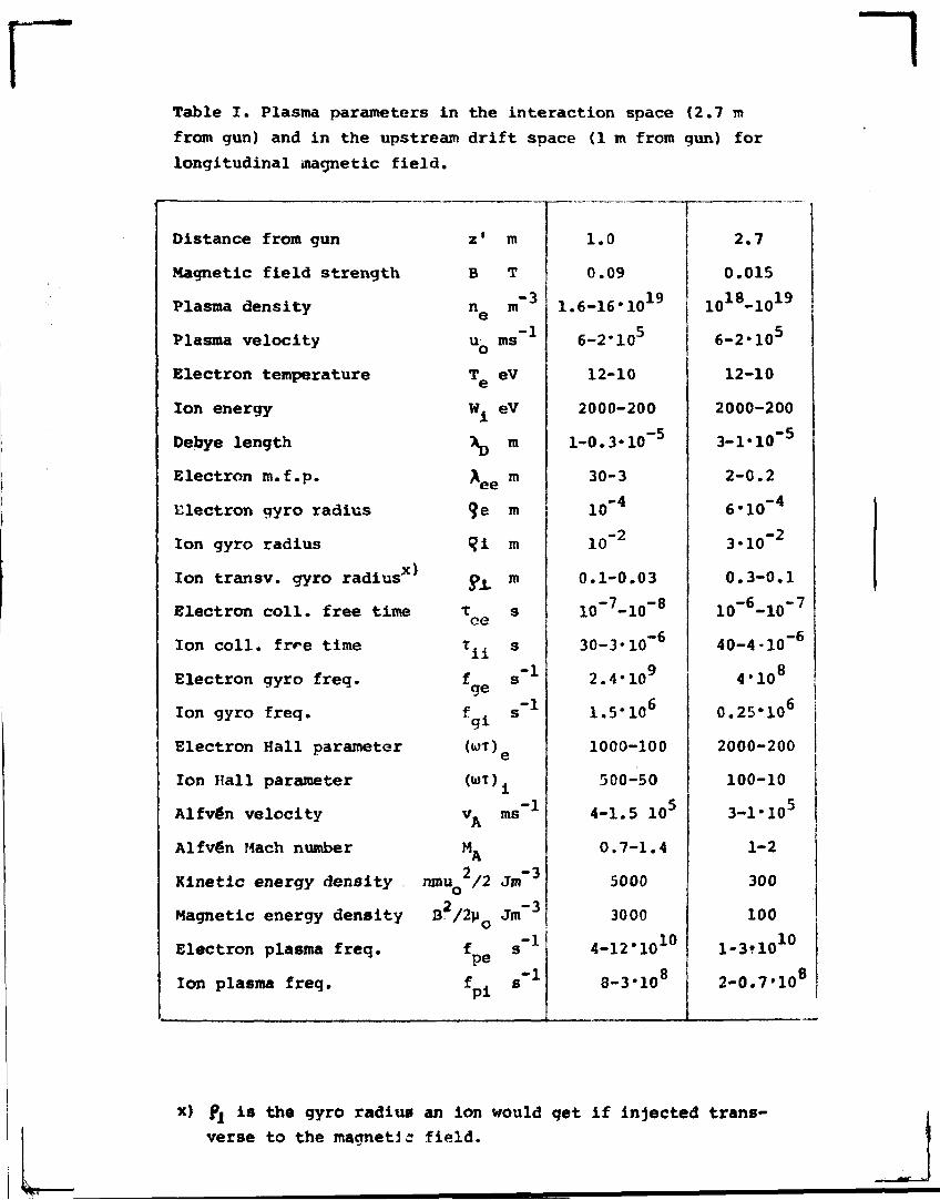
~lTable I. Plasma parameters in the interaction space (2.7 m
from gun) and in the upstream drift space (1 m from gun) for
longitudinal magnetic field.
Distance from gun
Magnetic field strength
Plasma density
Plasma velocity
Electron temperature
Ion energy
Debye length
Electron m.f.p.
Electron gyro radius
Ion gyro radius
x)Ion transv. gyro radius
Electron coll. free time
Ion coll. frre time
Electron gyro freq.
Ion gyro freq.
Electron Hall parameter
Ion Hall parameter
Alfvén velocity
Alfvén Mach number
Kinetic energy density
Magnetic energy density
Electron plasma freq.
Ion plasma freq.
z1
B
ne
uo
Te
Wi
9e
<?i
XOQ
xafge
fgi(U)T]
<»T]
vA
MA
ranuQ /2
o
fpe
m
T
m"3
ms" 1
eV
eV
m
i m
ID
m
m
s
s
s"1
s"1
ms
Jm"3
Jm"3
s"1
s"1
1.0
0.09
1.6-16*1019
6-2»105
12-10
2000-200
l-0.3«10"5
30-3
lo"4
lo"2
0.1-0.03
10"7-10"8
30-3*10"6
2.4'109
1.5*106
1000-100
500-50
4-1.5 105
0.7-1.4
5000
3000
4-12#1010
8-3'108
2.7
0.015
1018-1019
6-2»105
12-10
2000-200
3-1»10~5
2-0.2
6'10"4
3*10"2
0.3-0.1
10"6-10~7
40-4-10"6
4-108
0.25-106
2000-200
100-10
3-l'105
1-2
300
100
1-3.1010
2-0.7'108
x) fj is the gyro radius an ion would get if injected trans-
verse to the magnetic field.
a. Single particles follow in first
approximation magnetic field
lines even if they are curved.
b. A thin plasma beam becomes
self-polarized and proceeds
straight on by ExB-drift.
c. The polarization field is
short-circuited by depola-
rization currents and the
beam has to follow the curved
field.
d. A plasma beam with high conduc-
tivity and kinetic energy moves
straight on, "stretching and
pushing the magnetic field lines
aside".
e. Our experiment shows that in a
polarized beam the polarization
field is propagated backwards
and causes a deflection by ExB-
-drift in the direction opposite
to that in which the magnetic
field is curved.
•_-™a55^
d ZZZI
Fig.l Different types of behaviour of a plasma initially moving parallel to a magnetic
field when entering a region of curved field.
J
CONICALTHETA PINCH
PO
OHIFTSPACE
EXPANSIONSPACE
AXIAL GUIDE FIELD COILS
INTERACTIONSPACE
TRANSVERSE FIELD COILS
\
OOQOOQO D 0 0 0 0 Q O l ! n
\M\\\O O O O D O O O O D 0 Of fo01 , >
PUMP
tm
y yH
CROSS SECTION AND DEFLECTIONOF PLASMA BEAM
Fig.2. Section of experimental equipment. The plasma is formed in the theta-pinch gun (left) and
shot out into a longitudinal magnetic guiding field, which in the "interaction space" (right) may
be curved upwards or downwards (as shown by dashed field lines).
When the field is curved downwards the plasma beam is found to move upwards as shown. When entering
the curved field it also contracts and forms a vertical flat slab.
The coordinate system referred to in the text has its origin in the center of the interaction space.
_l
~l
Fig. 3 Photographic study of the beam cross-section in the
interaction region. The plasma hits an array of thin glass wires,
which emit light. The light phenomena give a rough idea of the
location and cross-section of the beam.
Left picture longitudinal field, right curved field.
For orientation white dots are superposed to mark the origin
and points with coordinates x = ±10, y = ±10, cf. fig. 2. In
the right picture a glass ring was added to mark the center.
It gave rise to the rather strong light near the center in that
picture.
Pictures exposed 12 ps after the plasma is emitted from the
gun. Exposure time 2 ys.
•&-PINCHPLASMA
GUN
REGION WITH CURVED-MAGNETIC FIELD
CHARGE SEPARATINGVB AND INERTIADRIFTS
E x B - DRIFT
CROSS SECTIONAND BOUNDARYOF BEAM
DEPOLARIZINGELECTRONCURRENTS
\ \
\ \
L B D I S T U R B E D* MAGNETIC
FIELD
ELECTRIC FIELD STRUCTUREILLUSTRATED BYEQUI POTENTIAL LINESIN xz-PLANE
Fig.4 Survey of experimental results
r ~i
fy=-R
Fig. 5 Theoretical model of magnetic field
Fig. 6 Transmission line model of backwards propagation
of electric field
r TRITA-EPP-77-23
PLASMA FLOW IN A CURVED MAGNETIC FIELD
Lennart Lindberg
Dept of Plasma Physics, Royal Institute of Technology, Stockholm,
Sweden
Sept 1977, 27 pp-« in English
A bean of collisionless nlasma is injected alone a longitudinal
magnetic field into a region of curved magnetic field. Two unore-
dicted phenomena are oosrrved: The beam becomes deflected in the
direction opposite to that in which the field is curved, and it
contracts to a flat slab in the plane of curvature of the magne-
tic field.
The plasma is produced by a conical theta-pinch aun and studied
by means of high speed photography, electric and magnetic probes,
ion analyzer, and spectroscopy.
The plasma beam is collisionless and its behaviour is in principle
understood on basis of gyro-center drift theory, A fraction of
the transverse electric field E = -v x D, which is induced when
the beam enters the curved magnetic field, is propagated upstream
and causes tho reverse deflection bv £ x B-drift. The upstream
propagation of the transverse electric field is due to electron
currents.
The circuit aspect on the plasma is important. The transverse
polarization current in the reoion with curved field connects to
a loop of depolarization currents upstream. The loop has limited
ability to carry current because of the collisionless character of
the plasma, curl E is almost zero and electric field components
parallel to the magnetic field arise. These play an essential role
producing run-away electrons, which have been detected. An increa-
sed electron temperature is observed when the plasma is shot into
the curved field. Run-away electrons alone might propagate the
electric field upstream in case the electron thermal velocity
is insufficient.
The phenomenon is of a general character and can be expected to
occur in a very wide range of densities. The lower density limit
is set by the condition for »elf-polarization, nm./r B 2 >> 12 2
or, which is equivalent, c /v. >> 1, where c is the velocity of
light, and v, the Alfvén velocity. The upper Unit is presumably
set by the requirement u T >> 1.
The phenomenon is likely to be of importance e.g. for injection of
plasma into magnetic bottles and in space and solar physics.
The paper illustrates the complexity of plasma flow phenomena and
the importance of close contact between experimental and theoreti-
cal work.
Key wordst Collisionless plasma, Magnetic plasma, Plasma dynamics,
Plasma beam, Plasma flow, Plasma magnetic field Interaction, Plas-
ma injection, Run-away electrons, Plasma diagnostics, Electric
probes, Faraday cup, Plasma spectroscopy.
~l