triscroll in-line exhaust silencer and vibration isolation ... · pdf filetriscroll in-line...
TRANSCRIPT

DR
AF
T
vacuum technologies
TriScroll In-line Exhaust Silencer and
Vibration Isolation
Part No. 699904410Rev. AMay 2008
INSTRUCTION MANUAL

DR
AF
T
TriScroll In-line Exhaust Silencer and Vibration Isolation
Copyright 2008Varian, Inc.

TriScroll In-line Exhaust Silencer and Vibration Isolation
DR
AF
T
Warranty
Products manufactured by Seller are warranted against defects in materials and workmanship for twelve (12) months from date of shipment thereof to Customer, and Seller’s liability under valid warranty claims is limited, at the option of Seller, to repair, replacement, or refund an equitable portion of the purchase price of the Product. Items expendable in normal use are not covered by this warranty. All warranty replacement or repair of parts shall be limited to equipment malfunctions which, in the sole opinion of Seller, are due or traceable to defects in original materials or workmanship. All obligations of Seller under this warranty shall cease in the event of abuse, accident, alteration, misuse, or neglect of the equipment. In-warranty repaired or replaced parts are warranted only for the remaining unexpired portion of the original warranty period applicable to the repaired or replaced parts. After expiration of the applicable warranty period, Customer shall be charged at the then current prices for parts, labor, and transportation.
When products are used with toxic chemicals, or in an atmosphere that is dangerous to the health of humans, or is environmentally unsafe, it will be the responsibility of the Customer to have the product cleaned by an independent agency skilled and approved in handling and cleaning contaminated materials before the product will be accepted by Varian, Inc. for repair and/or replacement.
Reasonable care must be used to avoid hazards. Seller expressly disclaims responsibility for loss or damage caused by use of its Products other than in accordance with proper operating procedures.
Except as stated herein, Seller makes no warranty, express or implied (either in fact or by operation of law), statutory or otherwise; and, except as stated herein, Seller shall have no liability under any warranty, express or implied (either in fact or by operation of law), statutory or otherwise. Statements made by any person, including representatives of Seller, which are inconsistent or in conflict with the terms of this warranty shall not be binding upon Seller unless reduced to writing and approved by an officer of Seller.
Warranty Replacement and AdjustmentAll claims under warranty must be made promptly after occurrence of circumstances giving rise thereto, and must be received within the applicable warranty period by Seller or its authorized representative. Such claims should include the Product serial number, the date of shipment, and a full description of the circumstances giving rise to the claim. Before any Products are returned for repair and/or adjustment, written authorization from Seller or its authorized representative for the return and instructions as to how and where these Products should be returned must be obtained. Any Product returned to Seller for examination shall be prepaid via the means of transportation indicated as acceptable by Seller. Seller reserves the right to reject any warranty claim not promptly reported and any warranty claim on any item that has been altered or has been returned by non-acceptable means of transportation. When any Product is returned for examination and inspection, or for any other reason, Customer shall be responsible for all damage resulting from improper packing or handling, and for loss in transit, notwithstanding any defect or non-conformity in the Product. In all cases, Seller has the sole responsibility for determining the cause and nature of failure, and Seller’s determination with regard thereto shall be final.
If it is found that Seller’s Product has been returned without cause and is still serviceable, Customer will be notified and the Product returned at its expense; in addition, a charge for testing and examination may be made on Products so returned. 3/1/00
iii

TriScroll In-line Exhaust Silencer and Vibration Isolation D
RA
FT
This page intentionally left blank.

TriScroll In-line Exhaust Silencer and Vibration Isolation
DR
AF
T
Preface
Documentation Conventions This manual uses the following documentation conventions:
WARNING Warnings indicate a particular procedure or practice, which if not followed correctly, could lead to serious injury.
CAUTION Cautions indicate a particular procedure or practice, which if not followed, could cause damage to the equipment.
NOTE Notes contain important information.
Before operating or servicing equipment, read and thoroughly understand all operation/maintenance manuals provided by Vacuum Technologies. Be aware of the hazards associated with this equipment, know how to recognize potentially hazardous conditions, and how to avoid them. Read carefully and strictly observe all cautions and warnings. The consequences of unskilled, improper, or careless operation of the equipment can be serious.
In addition, consult local, state, and national agencies regarding specific requirements and regulations. Address any safety, operation, and/or maintenance questions to your nearest Vacuum Technologies office.
v
TriScroll In-line Exhaust Silencer and Vibration Isolation D
RA
FT
This page intentionally left blank.

TriScroll In-line Exhaust Silencer and Vibration Isolation
DR
AF
T
TriScroll Vibration Isolation Kit
This document details the installation of Vibration Isolation Kits and optional Exhaust Silencer and Exhaust Muffler Kits for use with TriScroll pumps.
The Vibration Isolation Kit reduces vibration transmitted to the structure on which the rough pump is mounted. This kit, P/N PTSVIBISOKIT, consists of four (4) vibration isolation mounts that replace the standard feet supplied with the pump.
Installation Specific Issues
The Exhaust Silencer Kit - Dry Pump Conversions, P/N PTSREXSLRAB1, uses a cylindrical resonator chamber selected to attenuate the frequencies associated with the exhaust gas pulsation noise. The resonator is then plumbed to the exhaust line. The associated hardware for this connection is included in the kit. This kit generally provides all the noise reduction needed. The cylindrical resonator is installed in the flexible exhaust line included in the standard dry pump conversion kit.
The Exhaust Silencer Kit - Dry Pump Options, P/N PTSREXSLRAB2, also uses the cylindrical resonator but provides additional hardware allowing it to be mounted to instruments originally fitted with dry pumps.
The Exhaust Muffler Kit, P/N PTSREXMUFLAB1, is intended for use in installations where the exhaust line is routed to the inlet of a duct or fume hood. In these installations, a further reduction in exhaust pulsation is often required. This kit includes a filter/muffler, which is installed downstream of the resonator, and then plumbed to the exhaust line. Use the Muffler Kit in conjunction with the Silencer Kit for the maximum possible noise reduction. For maximum noise reduction it is important to make sure the exhaust line supplied with the instrument is replaced with the grey tube supplied with the dry pump conversion kit.
CAUTION The muffler is intended for noise reduction only, not gas containment (not warranted vacuum tight). If hazardous materials are to pass through the exhaust, route it directly to a house exhaust collection system.
When two rough pumps are used and their exhausts are teed together, install the Silencer Kit(s) and (if used) the Muffler Kit(s) upstream of the tee that joins the two pump exhaust lines. Replace the exhaust line downstream of the tee with the grey hose as above.
1-1

TriScroll In-line Exhaust Silencer and Vibration Isolation D
RA
FT
TriScroll Vibration Isolation KitTable 1-1 list the kits parts.
Installation
To install the unit:
1. Unscrew the M6 screws that secure the standard feet. If the standard feet are not present, go to step 2.
2. Position the flat washer under the screw’s head and place the M6 screw through the mount hole (Figure 1-1).
Figure 1-1 Vibration Isolation Kit Components
3. Position the mount with the round surface against the pump’s base and using a 5 mm wrench, screw in the M6 screw into the threaded hole in the base.
4. Carefully position the pump inside instrument cabinet.
5. If two pumps are used, and the inlet tubing between the pumps is a bellows, replace the bellows with the clear reinforced vacuum tubing included in the standard installation kit (1.5" or 1.25" ID depending on the installation). This prevents the pumps from shifting excessively due to compression of the bellows during system evacuation.
Table 1-1 TriScroll Vibration Isolation Kit, P/N: PTSVIBISOKIT
Part Name Qty. Used
Anti-vibratory, non-skidding mount 4
Screw, M6 x 1.0 x 25 mm long, SHC, SS 4
Washer M6 Flat, S/S 4
Anti-vibratory, non-skidding mounting foot
M6 x 1 x 25 mm long
M6 Flat Washer
1-2

TriScroll In-line Exhaust Silencer and Vibration Isolation
DR
AF
T
NOTE Ensure that:
❑ The pump is vertical during operation and that the mounts are not subjected to side loading once the pump is installed.
❑ No component of the installation is stretched or compressed so as to prevent free movement of the pump on the mounts.
NOTE ❑ Although the rubber-covered mount is non-skidding (Figure 1-2), if the application requires additional security, use the two holes in the mount’s flange, using additional screws - not included with this kit.
❑ Anti-vibratory mounts increase pump height by ¾” (19 mm).
Figure 1-2 Vibration Isolation Kit Installed
Figure 1-3 shows the foot dimensions.
Figure 1-3 Dimensions of Anti-vibratory, Non-skidding Mount
Anti-vibratory mounting foot
1-3

TriScroll In-line Exhaust Silencer and Vibration Isolation D
RA
FT
Performance
Vibration level in every direction (axis), transmitted to the surface the pump sits on, is significantly reduced. Typical vibration reduction levels are 75% for the TriScroll 600 pump.
TriScroll Exhaust Silencer KitTable 1-2 list the kits parts.
Installation
To install the unit:
1. If 1/2" Tygon tubing from pump exhaust is installed from a previous conversion, loosen it at the end away from the pump.
2. Insert the resonator into the exhaust line (Figure 1-4) and attach the included additional 1/2" Tygon tubing to the other end of the resonator. The resonator may be installed in either direction.
Figure 1-4 Exhaust Silencer Kit: Exploded View - For Systems Converted to Triscroll Pumps
Table 1-2 Exhaust Silencer Kit for Triscroll Pump Conversions: P/N PTSREXSLRAB1
Part Name Qty. Used
Tygon hose black .75" OD x .125" w x 36" long 1
Exhaust Silencer/Resonator Assembly 1
Hose Clamp 2
Mount, Adhesive Backed 4
Tie Wrap 4
1-4

TriScroll In-line Exhaust Silencer and Vibration Isolation
DR
AF
T
3. Cut the 36" supplied 1/2" Tygon tubing to a length convenient for the installation.
4. Reinstall the 1/2" hose barb x 3/8" NPT fitting and the 3/8" NPT x NW25 flange (Figure 1-4).
5. Secure all connections with hose clamps.
6. Reconnect the NW25 flange on the 1/2" Tygon tubing to the NW25 flange on the grey tubing supplied with the conversion kit.
7. Secure the resonator with the supplied mounts and cable ties, if desired.
TriScroll Exhaust Silencer KitTable 1-3 list the kits parts.
Table 1-3 Exhaust Silencer Kit for Triscroll Original Installations: P/N PTSREXSLRAB2
Part Name Qty. Used
Tygon hose black .75" OD x .125" w x 36" long 1
Exhaust Silencer/Resonator Assembly 1
Hose Clamp 4
Mount, Adhesive Backed 4
Tie Wrap 4
NW25 Clamp 2
NW25 Centering Ring 2
Flange, NW25 x 3/8" NPTF 2
Fitting, 3/8" NPTM x 1/2" hose 2
1-5

TriScroll In-line Exhaust Silencer and Vibration Isolation D
RA
FT
Installation
To install the unit:
1. Disconnect the house exhaust from the pump exhaust at the NW25 flange.
2. Cut one length of 1/2" Tygon tubing to at least 7 1/2" to go between the pump exhaust and the resonator (Figure 1-5). Cut the remaining length of tubing to any length convenient for the installation.
Figure 1-5 Exhaust Silencer Kit: Exploded View - Systems Originally with Triscroll Pumps
3. Install the NW25 flange that leads to the resonator to the pump exhaust; connect the other end of the assembly to the house exhaust NW25 flange.
4. Secure the resonator with the supplied mounts and cable ties, if desired.
Figure 1-6 shows the Silencer Kit installed.
Figure 1-6 Triscroll Pump with Silencer Kit Installed Toward Rear of Pump
To house exhaust
1-6

TriScroll In-line Exhaust Silencer and Vibration Isolation
DR
AF
T
Figure 1-7 gives pump interface dimensions.
Figure 1-7 Pump Interface with NW25 Exhaust Extension
NOTE The TriScroll 300 has an 1/4" NPT on the exhaust fitting, and an NW16 on the extension.
TriScroll Exhaust Muffler KitThis procedure consists of:
❑ “1. Installation - Clamp Installation to House Exhaust”
❑ “2. Installation - Tubing from Exhaust Muffler to House Exhaust” on page 1-9
Table 1-4 list the kits parts.
Table 1-4 Exhaust Muffler Kit for Triscroll Pumps:P/N PTSREXMUFLAB1
Part Name Qty. Used
Barb Fitting 3/8" NPT x 1/2" hose 2
KF25 clamp 2
KF25 center ring 2
NW25 to 3/8” NPT adaptor 2
Exhaust Muffler 1
Hose Clamp 2
Mount, Adhesive Backed 4
Tie Wrap 4
1-7

TriScroll In-line Exhaust Silencer and Vibration Isolation D
RA
FT
1. Installation - Clamp Installation to House Exhaust
To install the unit:
1. Clamp the inlet of the muffler (NW25) to the NW25 flange on the outlet of the 1/2" Tygon tubing downstream from resonator. The inlet of the muffler has three small holes in the flange (Figure 1-8).
Figure 1-8 Exhaust Muffler Kit: Exploded View
2. Clamp the outlet of the muffler (NW25) to the NW25 flange on the exhaust tubing leading to the house exhaust (replace tubing using tubing provided in standard installation kit); or to the exhaust line tee for installations where two pumps discharge into one exhaust tube.
3. If two pumps discharge into one house exhaust tube, fit each pump with one muffler, and join the lines downstream of the mufflers. This prevents restriction in the exhaust lines during pumpdown of the system.
4. Secure the muffler using adhesive mounts and cable ties.
1-8

TriScroll In-line Exhaust Silencer and Vibration Isolation
DR
AF
T
2. Installation - Tubing from Exhaust Muffler to House ExhaustTo install the unit:
1. Clamp the inlet of the muffler (NW25) to the NW25 flange on the outlet of 1/2" Tygon tubing downstream from resonator. The inlet of the muffler has three small holes in the flange (Figure 1-9).
Figure 1-9 Exhaust Muffler Kit: Exploded View - Tubing Between Muffler and House Exhaust
2. Clamp the outlet of the muffler (NW25) to the NW25 x 3/8" NPT fitting. Screw the 1/2" hose barb x 3/8" NPT fitting into the NW25 x 3/8" NPT fitting. Attach the remaining length of Tygon tubing and secure with a hose clamp.
3. Screw the second 1/2" hose barb x 3/8" NPT fitting into the second NW25 x 3/8" NPT fitting. Insert this into Tygon tubing and secure with a hose clamp.
4. Proceed as in steps (2) ~ (4) in “1. Installation - Clamp Installation to House Exhaust” on page 1-8.
CAUTION The muffler is designed for noise reduction only (not warranted gas tight). If hazardous gas containment is required, do not use this part.
1-9

TriScroll In-line Exhaust Silencer and Vibration Isolation D
RA
FT
This page intentionally left blank.

Request for Return Health and Safety Certification
1. Return authorization numbers (RA#) will not be issued for any product until this Certificate is completed and returned to a Varian, Inc. Customer Service Representative.
2. Pack goods appropriately and drain all oil from rotary vane and diffusion pumps (for exchanges please use the packing material from the replacement unit), making sure shipment documentation and package label clearly shows assigned Return Authorization Number (RA#) VVT cannot accept any return without such reference.
3. Return product(s) to the nearest location:
4. If a product is received at Varian, Inc. in a contaminated condition, the customer is held responsible for all costs incurred to ensure the safe handling of the product, and is liable for any harm or injury to Varian, Inc. employees occurring as a result of exposure to toxic or hazardous materials present in the product.
PLEASE FILL IN THE FAILURE REPORT SECTION ON THE NEXT PAGE
North and South America Europe and Middle East Asia and ROWVarian, Inc.
121 Hartwell Ave.Lexington, MA 02421Fax: (781) 860-9252
Varian S.p.A.Via F.lli Varian, 54
10040 Leini (TO) – ITALYFax: (39) 011 997 9350
Varian Vacuum TechnologiesLocal Office
For a complete list of phone/fax numbers see www.varianinc.com/vacuum
Do not write below this lineNotification (RA) #: ................................... Customer ID #: ........................................ Equipment #: ............................................
CUSTOMER INFORMATION
Company name: ......................................................................................................................................................................
Contact person: Name: ...................................................................................... Tel:............................................................
Fax: .......................................................................................... E-mail: .....................................................
Ship method: Shipping Collect #: .................................. P.O.#: .......................................................
Europe only: VAT Reg Number: ........... USA only: ❒Taxable ❒Non-taxable
Customer ship to: .................................................................... Customer bill to: .................................................................
.................................................................... .................................................................
.................................................................... .................................................................
PRODUCT IDENTIFICATION
Product Description Varian, Inc. Part Number Varian, Inc. Serial Number
TYPE OF RETURN (check appropriate box)❒ Paid Exchange ❒ Paid Repair ❒ Warranty Exchange ❒ Warranty Repair ❒ Loaner Return❒ Credit ❒ Shipping Error ❒ Evaluation Return ❒ Calibration ❒ Other
HEALTH and SAFETY CERTIFICATION
VARIAN, INC. CANNOT ACCEPT ANY BIOLOGICAL HAZARDS, RADIOACTIVE MATERIAL, ORGANIC METALS, OR MERCURY AT ITS FACILITY. CHECK ONE OF THE FOLLOWING:
❒ I confirm that the above product(s) has (have) NOT pumped or been exposed to any toxic or dangerous materials in aquantity harmful for human contact.
❒ I declare that the above product(s) has (have) pumped or been exposed to the following toxic or dangerous materials in a quantity harmful for human contact (Must be filled in):
Print Name................................................ Signature ................................................... Date ...............................
August 2003 — Page 1 of 2
ISOR E G I S T E R E D
9001
Request for Return Health and Safety Certification
Request for ReturnHealth and Safety Certification
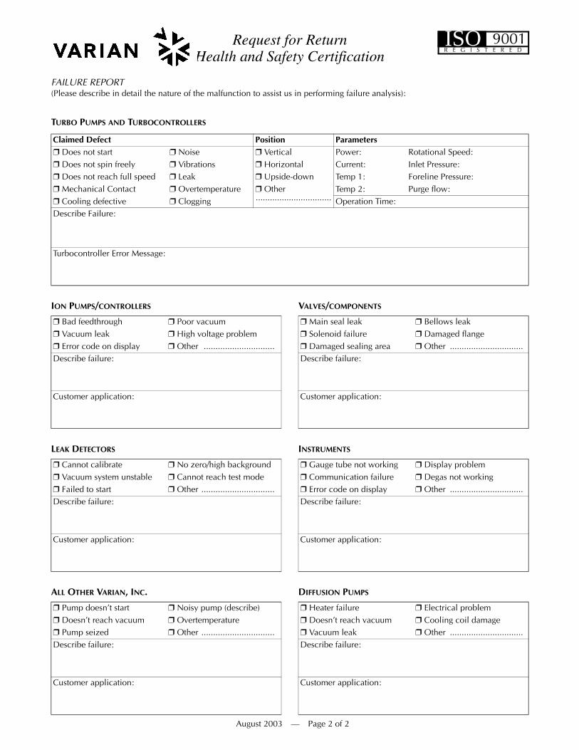
FAILURE REPORT (Please describe in detail the nature of the malfunction to assist us in performing failure analysis):
TURBO PUMPS AND TURBOCONTROLLERS
ION PUMPS/CONTROLLERS VALVES/COMPONENTS
LEAK DETECTORS INSTRUMENTS
ALL OTHER VARIAN, INC. DIFFUSION PUMPS
Claimed Defect Position Parameters❒ Does not start ❒ Noise ❒ Vertical Power: Rotational Speed:❒ Does not spin freely ❒ Vibrations ❒ Horizontal Current: Inlet Pressure:❒ Does not reach full speed ❒ Leak ❒ Upside-down Temp 1: Foreline Pressure:❒ Mechanical Contact ❒ Overtemperature ❒ Other
................................Temp 2: Purge flow:
❒ Cooling defective ❒ Clogging Operation Time:Describe Failure:
Turbocontroller Error Message:
❒ Bad feedthrough ❒ Poor vacuum ❒ Main seal leak ❒ Bellows leak❒ Vacuum leak ❒ High voltage problem ❒ Solenoid failure ❒ Damaged flange❒ Error code on display ❒ Other .............................. ❒ Damaged sealing area ❒ Other ...............................Describe failure: Describe failure:
Customer application: Customer application:
❒ Cannot calibrate ❒ No zero/high background ❒ Gauge tube not working ❒ Display problem❒ Vacuum system unstable ❒ Cannot reach test mode ❒ Communication failure ❒ Degas not working❒ Failed to start ❒ Other ............................... ❒ Error code on display ❒ Other ...............................Describe failure: Describe failure:
Customer application: Customer application:
❒ Pump doesn’t start ❒ Noisy pump (describe) ❒ Heater failure ❒ Electrical problem❒ Doesn’t reach vacuum ❒ Overtemperature ❒ Doesn’t reach vacuum ❒ Cooling coil damage❒ Pump seized ❒ Other ............................... ❒ Vacuum leak ❒ Other ...............................Describe failure: Describe failure:
Customer application: Customer application:
August 2003 — Page 2 of 2
ISOR E G I S T E R E D
9001


Sales and Service Offices
04/08
CanadaCentral coordination through:Varian, Inc.121 Hartwell AvenueLexington, MA 02421USATel.: +1 781 861 7200Toll-Free: +1 800 882 7426Fax: +1 781 860 5437
ChinaVarian Technologies China, Ltd.Room 1648Central Tower South WingBeijing Junefield PlazaNo. 10 XuanWuMenWai StreetBeijing 100052P. R. ChinaTel.: +86 (10) 6310 8550Toll-Free: 800 820 6556Fax: +86 (10) 6310 0141
FranceVarian s.a.7 avenue des TropiquesZ.A. de Courtaboeuf - B.P. 1291941 Les Ulis cedexFranceTel.: +33 (0) 1 69 86 38 84Fax: +33 (0) 1 69 86 29 88
BeneluxVarian Vacuum TechnologiesHerculesweg 84338 PL MiddelburgThe NetherlandsTel.: +31 118 671570Fax: +31 118 671569
Germany & AustriaVarian Deutschland GmbHAlsfelder Strasse 6Postfach 11 14 3564289 DarmstadtGermanyTel.: +49 (0) 6151 703 353Fax: +49 (0) 6151 703 302
IndiaVarian India Pvt. Ltd.205-A, "A" wing of Galleria2nd floor, Hiranandani GardensPowai, Mumbai-400 076IndiaTel.: +91 22 2570 8595/8597Fax: +91 22 2570 8599Mobile: +91 98 679 55969
ItalyVarian, Inc.via F.lli Varian 5410040 Leini, (Torino)ItalyTel.: +39 011 997 9111Toll-Free: 00 800 234 234 00Fax: +39 011 997 9350
JapanVarian Technologies Japan, Ltd.8th FloorSumitomo Shibaura Building4-16-36 Shibaura Minato-kuTokyo 108JapanTel.: +81 3 5232 1253Toll-Free: 0120 655 040Fax: +81 3 5232 1710
KoreaVarian Technologies Korea, Ltd.Shinsa 2nd Bldg. 2F966-5 Daechi-dongKangnam-gu, SeoulKorea 135-280Tel.: +82 2 3452 2452Toll-Free: 080 222 2452Fax: +82 2 3452 2451
MexicoVarian, S. de R.L. de C.V.Concepcion Beistegui No 109Col Del ValleC.P. 03100Mexico, D.F.Tel.: +52 5 523 9465Fax: +52 5 523 9472
TaiwanVarian Technologies Asia, Ltd.14F-6, No. 77, Hsin Tai Wu Road, Sec. 1Hsi chih, Taipei HsienTaiwan, R.O.C.Tel.: +886 2 2698 9555Toll Free: 0800 051 342 Fax: +886 2 2698 96782
UK & IrelandVarian Ltd.6 Mead RoadOxford Industrial ParkYarnton, Oxford OX5 1QUUKTel.: +44 (0) 1865 291570Fax: +44 (0) 1865 291571
United StatesVarian, Inc121 Hartwell AvenueLexington, MA 02421USATel.: +1 781 861 7200Toll-Free: +1 800 882 7426Fax: +1 781 860 5437
Other CountriesVarian Vacuum Technologiesvia F.lli Varian 5410040 Leini, (Torino)ItalyTel: (39) 011 997 9 111Fax: (39) 011 997 9 350
Customer Support and Service:
North AmericaTel: 1 (800) 882-7426 (toll-free)[email protected]
EuropeTel: 00 (800) 234 234 00 (toll-free)[email protected]
JapanTel: (81) 3 5232 1253 (dedicated line)[email protected]
KoreaTel (82) 2 3452 2452 (dedicated line)[email protected]
TaiwanTel: 0 (800) 051 342 (toll-free)[email protected]
Worldwide Web Site, Catalog and On-line Orders:www.varianinc.com
Representatives in most countries