tripod-supported offshore wind turbines: modal and coupled
TRANSCRIPT

Journal of
Marine Science and Engineering
Article
Tripod-Supported Offshore Wind Turbines: Modaland Coupled Analysis and a Parametric Study UsingX-SEA and FAST
Pasin Plodpradit 1, Van Nguyen Dinh 2 and Ki-Du Kim 1,*1 Department of Civil and Environmental Engineering, Konkuk University, 120 Neungdong-ro,
Seoul 05029, Korea; [email protected] MaREI Centre for Marine and Renewable Energy, ERI, University College Cork, P43C573 Cork, Ireland;
[email protected] or [email protected]* Correspondence: [email protected]
Received: 16 May 2019; Accepted: 31 May 2019; Published: 9 June 2019
Abstract: This paper presents theoretical aspects and an extensive numerical study of the coupledanalysis of tripod support structures for offshore wind turbines (OWTs) by using X-SEA and FAST v8programs. In a number of site conditions such as extreme and longer period waves, fast installation,and lighter foundations, tripod structures are more advantageous than monopile and jacket structures.In the implemented dynamic coupled analysis, the sub-structural module in FAST was replaced bythe X-SEA offshore substructure analysis component. The time-histories of the reaction forces and theturbine loads were then calculated. The results obtained from X-SEA and from FAST were in goodagreement. The pile-soil-structure interaction (PSSI) was included for reliable evaluation of OWTstructural systems. The superelement concept was introduced to reduce the computational time.Modal, coupled and uncoupled analyses of the NREL 5MW OWT-tripod support structure includingPSSI were carried out and the discussions on the natural frequencies, mode shapes and resulteddisplacements are presented. Compared to the uncoupled models, the physical interaction betweenthe tower and the support structure in the coupled models resulted in smaller responses. Comparedto the fixed support structures, i.e., when PSSI is not included, the piled-support structure has lowernatural frequencies and larger responses attributed to its actual flexibility. The models using pilesuperelements are computationally efficient and give results that are identical to the common finiteelement models.
Keywords: offshore wind turbine; tripod support structures; coupled analysis; uncoupled analysis;soil-pile-structure interaction; superelement
1. Introduction
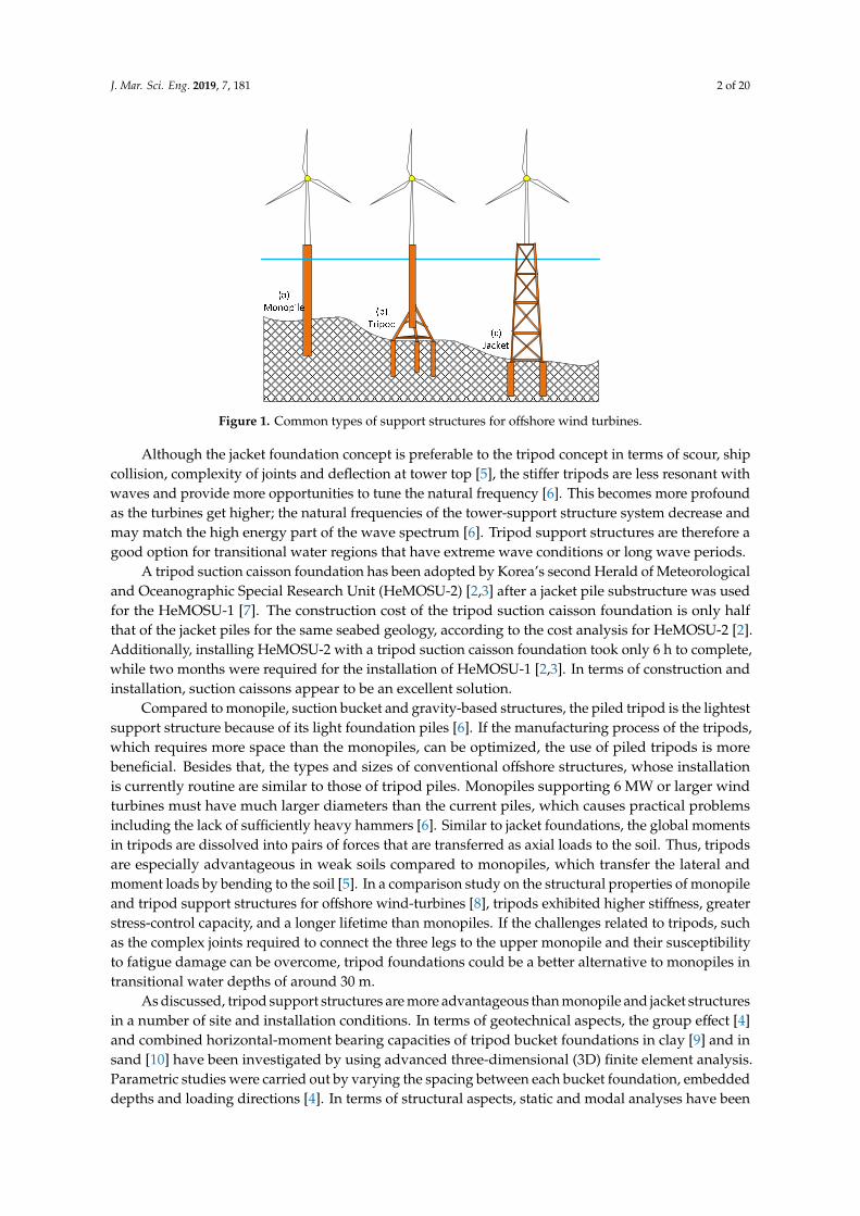
Among the common types of fixed-bottom substructures, shown in Figure 1, monopile structuresare most suitable for regions with shallow water depths (less than 30 m) [1]. Tripod and jacket structurescan be constructed in transitional water depths (between 30 and 50 m). An alternative design thatmakes use of the various advantages of both monopile and jacket structures is known as the tripodsupport structure. The main part consists of a mono pile tubular section and the lower part consistsof braces and three legs. Compared to a standard lattice structure, the tripod support structure isconsidered to be a relatively lightweight three-legged steel jacket. The central column beneath thetower and turbine transfers the forces from the tower into the three inclined members. In order toanchor the tripod to the seabed, piles are usually installed at each leg position. Suction caisson [2,3]and suction buckets [4] can be used to support the tripod structures, which have good stability andoverall stiffness.
J. Mar. Sci. Eng. 2019, 7, 181; doi:10.3390/jmse7060181 www.mdpi.com/journal/jmse
J. Mar. Sci. Eng. 2019, 7, 181 2 of 20
J. Mar. Sci. Eng. 2019, 6, x FOR PEER REVIEW 2 of 20
Figure 1. Common types of support structures for offshore wind turbines.
Although the jacket foundation concept is preferable to the tripod concept in terms of scour, ship collision, complexity of joints and deflection at tower top [5], the stiffer tripods are less resonant with waves and provide more opportunities to tune the natural frequency [6]. This becomes more profound as the turbines get higher; the natural frequencies of the tower-support structure system decrease and may match the high energy part of the wave spectrum [6]. Tripod support structures are therefore a good option for transitional water regions that have extreme wave conditions or long wave periods.
A tripod suction caisson foundation has been adopted by Korea’s second Herald of Meteorological and Oceanographic Special Research Unit (HeMOSU-2) [2,3] after a jacket pile substructure was used for the HeMOSU-1 [7]. The construction cost of the tripod suction caisson foundation is only half that of the jacket piles for the same seabed geology, according to the cost analysis for HeMOSU-2 [2]. Additionally, installing HeMOSU-2 with a tripod suction caisson foundation took only 6 h to complete, while two months were required for the installation of HeMOSU-1 [2,3]. In terms of construction and installation, suction caissons appear to be an excellent solution.
Compared to monopile, suction bucket and gravity-based structures, the piled tripod is the lightest support structure because of its light foundation piles [6]. If the manufacturing process of the tripods, which requires more space than the monopiles, can be optimized, the use of piled tripods is more beneficial. Besides that, the types and sizes of conventional offshore structures, whose installation is currently routine are similar to those of tripod piles. Monopiles supporting 6 MW or larger wind turbines must have much larger diameters than the current piles, which causes practical problems including the lack of sufficiently heavy hammers [6]. Similar to jacket foundations, the global moments in tripods are dissolved into pairs of forces that are transferred as axial loads to the soil. Thus, tripods are especially advantageous in weak soils compared to monopiles, which transfer the lateral and moment loads by bending to the soil [5]. In a comparison study on the structural properties of monopile and tripod support structures for offshore wind-turbines [8], tripods exhibited higher stiffness, greater stress-control capacity, and a longer lifetime than monopiles. If the challenges related to tripods, such as the complex joints required to connect the three legs to the upper monopile and their susceptibility to fatigue damage can be overcome, tripod foundations could be a better alternative to monopiles in transitional water depths of around 30 m.
As discussed, tripod support structures are more advantageous than monopile and jacket structures in a number of site and installation conditions. In terms of geotechnical aspects, the group effect [4] and combined horizontal-moment bearing capacities of tripod bucket foundations in clay [9] and in sand [10] have been investigated by using advanced three-dimensional (3D) finite element analysis. Parametric studies were carried out by varying the spacing between each bucket foundation, embedded depths and loading directions [4]. In terms of structural aspects, static and modal analyses
Figure 1. Common types of support structures for offshore wind turbines.
Although the jacket foundation concept is preferable to the tripod concept in terms of scour, shipcollision, complexity of joints and deflection at tower top [5], the stiffer tripods are less resonant withwaves and provide more opportunities to tune the natural frequency [6]. This becomes more profoundas the turbines get higher; the natural frequencies of the tower-support structure system decrease andmay match the high energy part of the wave spectrum [6]. Tripod support structures are therefore agood option for transitional water regions that have extreme wave conditions or long wave periods.
A tripod suction caisson foundation has been adopted by Korea’s second Herald of Meteorologicaland Oceanographic Special Research Unit (HeMOSU-2) [2,3] after a jacket pile substructure was usedfor the HeMOSU-1 [7]. The construction cost of the tripod suction caisson foundation is only halfthat of the jacket piles for the same seabed geology, according to the cost analysis for HeMOSU-2 [2].Additionally, installing HeMOSU-2 with a tripod suction caisson foundation took only 6 h to complete,while two months were required for the installation of HeMOSU-1 [2,3]. In terms of construction andinstallation, suction caissons appear to be an excellent solution.
Compared to monopile, suction bucket and gravity-based structures, the piled tripod is the lightestsupport structure because of its light foundation piles [6]. If the manufacturing process of the tripods,which requires more space than the monopiles, can be optimized, the use of piled tripods is morebeneficial. Besides that, the types and sizes of conventional offshore structures, whose installationis currently routine are similar to those of tripod piles. Monopiles supporting 6 MW or larger windturbines must have much larger diameters than the current piles, which causes practical problemsincluding the lack of sufficiently heavy hammers [6]. Similar to jacket foundations, the global momentsin tripods are dissolved into pairs of forces that are transferred as axial loads to the soil. Thus, tripodsare especially advantageous in weak soils compared to monopiles, which transfer the lateral andmoment loads by bending to the soil [5]. In a comparison study on the structural properties of monopileand tripod support structures for offshore wind-turbines [8], tripods exhibited higher stiffness, greaterstress-control capacity, and a longer lifetime than monopiles. If the challenges related to tripods, suchas the complex joints required to connect the three legs to the upper monopile and their susceptibilityto fatigue damage can be overcome, tripod foundations could be a better alternative to monopiles intransitional water depths of around 30 m.
As discussed, tripod support structures are more advantageous than monopile and jacket structuresin a number of site and installation conditions. In terms of geotechnical aspects, the group effect [4]and combined horizontal-moment bearing capacities of tripod bucket foundations in clay [9] and insand [10] have been investigated by using advanced three-dimensional (3D) finite element analysis.Parametric studies were carried out by varying the spacing between each bucket foundation, embeddeddepths and loading directions [4]. In terms of structural aspects, static and modal analyses have been
J. Mar. Sci. Eng. 2019, 7, 181 3 of 20
used to study the structural properties of tripod support structures for offshore wind-turbines [8].A finite element model of a tripod substructure was constructed for global optimization of the bestdesign considering uncertainties [11]. In a recent design of tripod foundation, the superstructure of theturbine was first simulated under wind and wave dynamic loading using FAST (Fatigue, Aerodynamic,Structures and Turbulence)—a CAE tool developed by the National Renewable Energy Laboratory(NREL), USA, to obtain time histories of internal actions for the pylons [12] using 3D finite elementanalysis software. These iterative analyses were utilized to obtain the required pile lengths andcross sections for tripod options [12]. However, the structural analyses and design of tripod supportstructures under simultaneous action of various environmental and operational conditions are lessreported in the literature.
As soil models are generally complicated and are very expensive in terms of computing time [13],the simulation codes for offshore wind turbines often exclude the detailed modeling of soil-structureinteraction [14]. Simpler approaches have therefore been adopted in the literature or the assumptionof a support structure clamped at the seabed has been used [13]. A coupled, linear approach withsix directions and soil-structure interaction matrices was introduced to modify the FAST simulationcode [13]. The dynamic soil properties obtained by comparing nonlinear spring models of soils andexperimental results were then incorporated [14]. Moreover, an offshore wind turbine (OWT) supportstructure must withstand the environmental and operational loading without failure. The behavior ofthe surface layer of soft, poorly consolidated marine clays and the stiffer clay or sand strata underthis loading, and their influence on the responses of the foundation-turbine system are also importantconsiderations. An analysis approach that considers the simultaneous interaction among the turbine,the tower, the support structure and the soil layers, the so-called coupled analysis, is required toensure the safety of all structural components and the serviceability of the OWT system [15]. However,lengthy computation time for the coupled analysis of complex systems is an issue [16].
This paper therefore addresses the lack of coupled analysis of tripod support structures for offshorewind turbines under the simultaneous actions of various environmental and operational conditions,and develops efficient measures to reduce the computation times of the coupled analysis. In orderto reduce the excessive computation times for the coupled analysis of a complex offshore supportstructure—a wind turbine—the superelement modeling technique was combined with the modaltruncation augmentation concept by using the Craig–Bampton (C-B) method [17]. The procedure fordynamic coupled analysis proposed in this study was implemented in the X-SEA program, a 3-Dfinite element analysis software developed by the authors for the analysis and design of fixed andfloating offshore structures for the oil/gas and offshore wind energy industry [18,19]. The procedurewas validated by FAST v8 [20]. Theoretical aspects of the coupled analysis approach using X-SEAwere initially discussed in the study of jacket structures [21] and are extensively described in thispaper for tripod support structures. The soil-pile-structure interaction formulation was included inthe implementation. However, the differences in soil conditions among the supports [22], the seismicloading [23,24], and the combination of seismic and aerodynamic loading [25] will be consideredin a future study. The displacements resulting from the coupled analysis of the tripod structureare compared with that from the uncoupled analysis. A parametric study of an NREL 5MW OWTsupported by a tripod structure using coupled analysis with soil-pile interactions is also carried out.
2. Development of Coupled Analysis for OWT and Tripod Support Structures
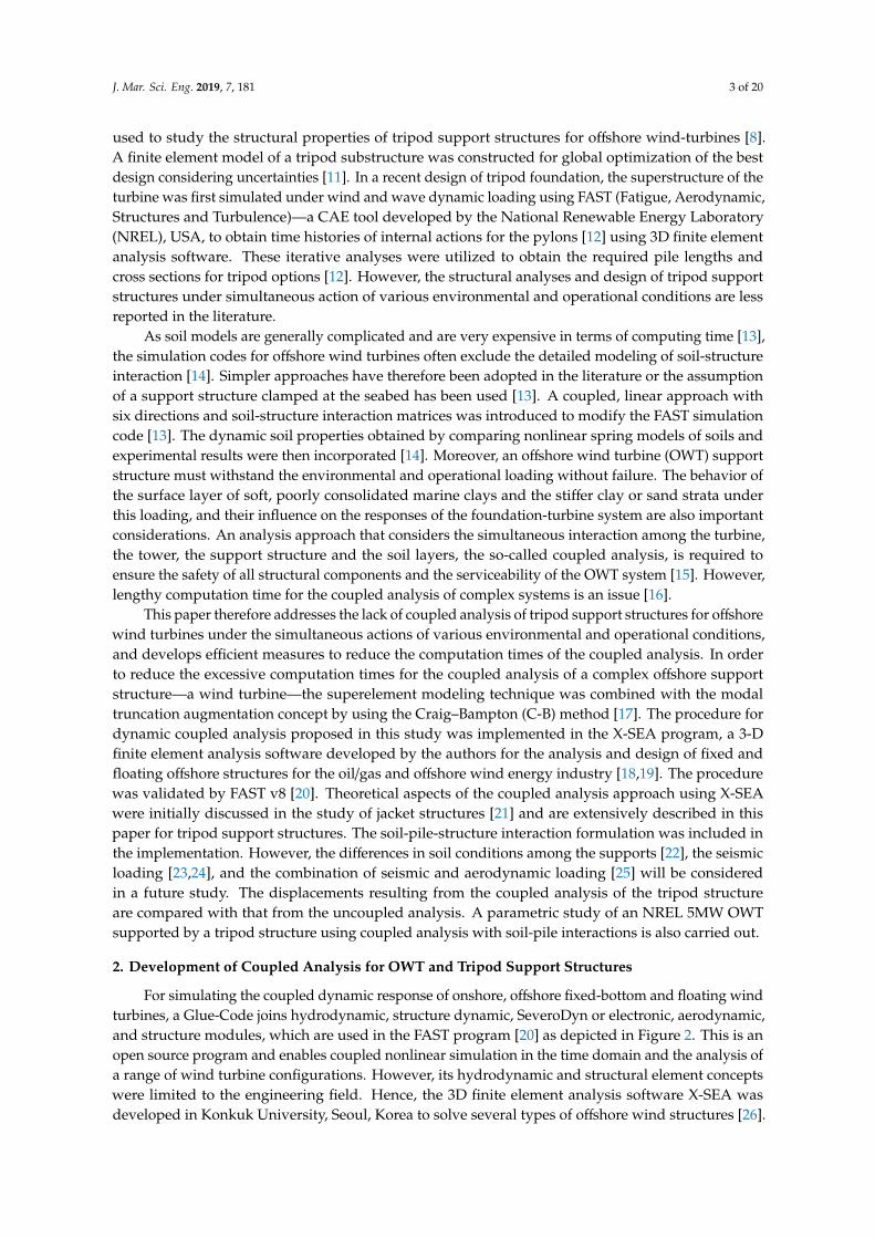
For simulating the coupled dynamic response of onshore, offshore fixed-bottom and floating windturbines, a Glue-Code joins hydrodynamic, structure dynamic, SeveroDyn or electronic, aerodynamic,and structure modules, which are used in the FAST program [20] as depicted in Figure 2. This is anopen source program and enables coupled nonlinear simulation in the time domain and the analysis ofa range of wind turbine configurations. However, its hydrodynamic and structural element conceptswere limited to the engineering field. Hence, the 3D finite element analysis software X-SEA wasdeveloped in Konkuk University, Seoul, Korea to solve several types of offshore wind structures [26].

J. Mar. Sci. Eng. 2019, 7, 181 4 of 20
The solution options of X-SEA range from simple static to highly advanced nonlinear dynamic analysis.In the case of uncoupled analysis, X-SEA receives the components of forces (Fx, Fy and Fz) and moments(Mx, My and Mz) at the top of the tower from FAST v8 and applies the loads to the support structure asshown in Figure 3a. The coupled analysis, which interchanges modules between the two programs isachieved through a modular interface and coupler as illustrated in Figure 3b.
J. Mar. Sci. Eng. 2019, 6, x FOR PEER REVIEW 4 of 20
structures [26]. The solution options of X-SEA range from simple static to highly advanced nonlinear dynamic analysis. In the case of uncoupled analysis, X-SEA receives the components of forces ( xF ,
yF and zF ) and moments ( xM , yM and zM ) at the top of the tower from FAST v8 and applies the loads to the support structure as shown in Figure 3a. The coupled analysis, which interchanges modules between the two programs is achieved through a modular interface and coupler as illustrated in Figure 3b.
Figure 2. The concept of the interchange substructure module of the FAST V.8 program.
(a) Uncoupled analysis (b) Coupled analysis
Figure 3. The concepts of uncoupled and coupled analysis.
The coupling of the substructure module in FAST V.8 program is loosened and replaced by that of X-SEA as illustrated in Figure 4. At the exchange position, the eighteen components of motion represented in the displacement u , velocity u and acceleration u vectors are the input to the present program from the structural dynamic module in the FAST program. The six components of action FTP from the X-SEA are input to the structural dynamic module in the FAST program.
Figure 2. The concept of the interchange substructure module of the FAST V.8 program.
J. Mar. Sci. Eng. 2019, 6, x FOR PEER REVIEW 4 of 20
structures [26]. The solution options of X-SEA range from simple static to highly advanced nonlinear dynamic analysis. In the case of uncoupled analysis, X-SEA receives the components of forces ( xF ,
yF and zF ) and moments ( xM , yM and zM ) at the top of the tower from FAST v8 and applies the loads to the support structure as shown in Figure 3a. The coupled analysis, which interchanges modules between the two programs is achieved through a modular interface and coupler as illustrated in Figure 3b.
Figure 2. The concept of the interchange substructure module of the FAST V.8 program.
(a) Uncoupled analysis (b) Coupled analysis
Figure 3. The concepts of uncoupled and coupled analysis.
The coupling of the substructure module in FAST V.8 program is loosened and replaced by that of X-SEA as illustrated in Figure 4. At the exchange position, the eighteen components of motion represented in the displacement u , velocity u and acceleration u vectors are the input to the present program from the structural dynamic module in the FAST program. The six components of action FTP from the X-SEA are input to the structural dynamic module in the FAST program.
Figure 3. The concepts of uncoupled and coupled analysis.
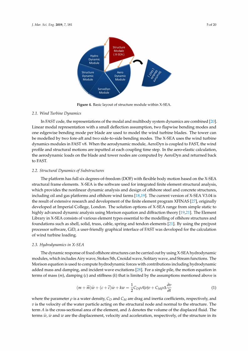
The coupling of the substructure module in FAST V.8 program is loosened and replaced by thatof X-SEA as illustrated in Figure 4. At the exchange position, the eighteen components of motionrepresented in the displacement u, velocity
.u
and acceleration ..u
vectors are the input to the presentprogram from the structural dynamic module in the FAST program. The six components of action FTPfrom the X-SEA are input to the structural dynamic module in the FAST program.
J. Mar. Sci. Eng. 2019, 7, 181 5 of 20J. Mar. Sci. Eng. 2019, 6, x FOR PEER REVIEW 5 of 20
Figure 4. Basic layout of structure module within X-SEA.
2.1. Wind Turbine Dynamics
In FAST code, the representations of the modal and multibody system dynamics are combined [20]. Linear modal representation with a small deflection assumption, two flapwise bending modes and one edgewise bending mode per blade are used to model the wind turbine blades. The tower can be modelled by two fore-aft and two side-to-side bending modes. The X-SEA uses the wind turbine dynamics modules in FAST v8. When the aerodynamic module, AeroDyn is coupled to FAST, the wind profile and structural motions are inputted at each coupling time step. In the aero-elastic calculation, the aerodynamic loads on the blade and tower nodes are computed by AeroDyn and returned back to FAST.
2.2. Structural Dynamics of Substructures
The platform has full six degrees-of-freedom (DOF) with flexible body motion based on the X-SEA structural frame elements. X-SEA is the software used for integrated finite element structural analysis, which provides the nonlinear dynamic analysis and design of offshore steel and concrete structures, including oil and gas platforms and offshore wind farms [18,19]. The current version of X-SEA V3.04 is the result of extensive research and development of the finite element program XFINAS [27], originally developed at Imperial College, London. The solution options of X-SEA range from simple static to highly advanced dynamic analysis using Morison equation and diffraction theory [19,21]. The Element Library in X-SEA consists of various element types essential to the modelling of offshore structures and foundations such as shell, solid, truss, cable, spring and tendon elements [21]. By using the pre/post processor software, GiD, a user-friendly graphical interface of FAST was developed for the calculation of wind turbine loading.
2.3. Hydrodynamics in X-SEA
The dynamic response of fixed offshore structures can be carried out by using X-SEA hydrodynamic modules, which includes Airy wave, Stokes 5th, Cnoidal wave, Solitary wave, and Stream functions. The Morison equation is used to compute hydrodynamic forces with contributions including hydrodynamic added mass and damping, and incident wave excitations [28]. For a single pile, the motion equation in terms of mass (m), damping (c) and stiffness (k) that is limited by the assumptions mentioned above is 𝑚 +𝑚)𝑤 + 𝑐 + )𝑤 + 𝑘𝑤 = 12𝐶 𝜌𝐴|𝑣|𝑣 + 𝐶 𝜌∆𝜕𝑣𝜕𝑡 (1)
where the parameter 𝜌 is a water density, DC and MC are drag and inertia coefficients, respectively, and v is the velocity of the water particle acting on the structural node and normal to the structure. The term A is the cross-sectional area of the element, and Δ denotes the volume of the displaced fluid. The terms 𝑤 , 𝑤 and w are the displacement, velocity and acceleration,
Figure 4. Basic layout of structure module within X-SEA.
2.1. Wind Turbine Dynamics
In FAST code, the representations of the modal and multibody system dynamics are combined [20].Linear modal representation with a small deflection assumption, two flapwise bending modes andone edgewise bending mode per blade are used to model the wind turbine blades. The tower canbe modelled by two fore-aft and two side-to-side bending modes. The X-SEA uses the wind turbinedynamics modules in FAST v8. When the aerodynamic module, AeroDyn is coupled to FAST, the windprofile and structural motions are inputted at each coupling time step. In the aero-elastic calculation,the aerodynamic loads on the blade and tower nodes are computed by AeroDyn and returned backto FAST.
2.2. Structural Dynamics of Substructures
The platform has full six degrees-of-freedom (DOF) with flexible body motion based on the X-SEAstructural frame elements. X-SEA is the software used for integrated finite element structural analysis,which provides the nonlinear dynamic analysis and design of offshore steel and concrete structures,including oil and gas platforms and offshore wind farms [18,19]. The current version of X-SEA V3.04 isthe result of extensive research and development of the finite element program XFINAS [27], originallydeveloped at Imperial College, London. The solution options of X-SEA range from simple static tohighly advanced dynamic analysis using Morison equation and diffraction theory [19,21]. The ElementLibrary in X-SEA consists of various element types essential to the modelling of offshore structures andfoundations such as shell, solid, truss, cable, spring and tendon elements [21]. By using the pre/postprocessor software, GiD, a user-friendly graphical interface of FAST was developed for the calculationof wind turbine loading.
2.3. Hydrodynamics in X-SEA
The dynamic response of fixed offshore structures can be carried out by using X-SEA hydrodynamicmodules, which includes Airy wave, Stokes 5th, Cnoidal wave, Solitary wave, and Stream functions. TheMorison equation is used to compute hydrodynamic forces with contributions including hydrodynamicadded mass and damping, and incident wave excitations [28]. For a single pile, the motion equation interms of mass (m), damping (c) and stiffness (k) that is limited by the assumptions mentioned above is
(m + m)..w + (c + c)
.w + kw =
12
CDρA|v|v + CMρ∆∂v∂t
(1)
where the parameter ρ is a water density, CD and CM are drag and inertia coefficients, respectively, andv is the velocity of the water particle acting on the structural node and normal to the structure. Theterm A is the cross-sectional area of the element, and ∆ denotes the volume of the displaced fluid. Theterms
..w,
.w and w are the displacement, velocity and acceleration, respectively, of the structure in its
J. Mar. Sci. Eng. 2019, 7, 181 6 of 20
local coordinate, which are normal to or in its longitudinal axis. When the motion of the structure isconsidered, the inertia force is reduced by a factor proportional to the structural acceleration, and thedrag force is reduced by the relative velocity and given in the form:
m = ρ(CM − 1)∆c = CDρAv
(2)
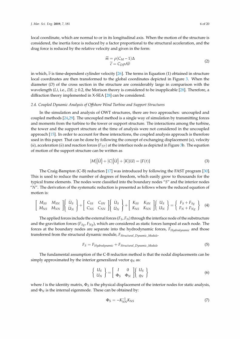
in which, v is time-dependent cylinder velocity [26]. The terms in Equation (1) obtained in structurelocal coordinates are then transformed to the global coordinates depicted in Figure 3. When thediameter (D) of the cross section in the structure are considerably large in comparison with thewavelength (L), i.e., D/L ≥ 0.2, the Morison theory is considered to be inapplicable [28]. Therefore, adiffraction theory implemented in X-SEA [28] can be considered.
2.4. Coupled Dynamic Analysis of Offshore Wind Turbine and Support Structures
In the simulation and analysis of OWT structures, there are two approaches: uncoupled andcoupled methods [24,29]. The uncoupled method is a single way of simulation by transmitting forcesand moments from the turbine to the tower or support structure. The interactions among the turbine,the tower and the support structure at the time of analysis were not considered in the uncoupledapproach [15]. In order to account for these interactions, the coupled analysis approach is thereforeused in this paper. That can be done by following the concept of exchanging displacement (u), velocity(
.u), acceleration (
..u) and reaction forces (FTP) at the interface node as depicted in Figure 3b. The equation
of motion of the support structure can be written as
[M] ..U+ [C]
.U+ [K]U =
F(t)
(3)
The Craig-Bampton (C-B) reduction [17] was introduced by following the FAST program [30].This is used to reduce the number of degrees of freedom, which easily grow to thousands for thetypical frame elements. The nodes were classified into the boundary nodes “S” and the interior nodes“N”. The derivation of the systematic reduction is presented as follows where the reduced equation ofmotion is:[
MSS MSNMNS MNN
]..US..UN
+
[CSS CSNCNS CNN
].
US.UN
+
[KSS KSNKNS KNN
]USUN
=
FS + FSgFN + FNg
(4)
The applied forces include the external forces (FS, FN) through the interface node of the substructureand the gravitation forces (FSg, FNg), which are considered as static forces lumped at each node. Theforces at the boundary nodes are separate into the hydrodynamic forces, FHydrodynamic and thosetransferred from the structural dynamic module, FStructural_Dynamic_Module.
FS = FHydrodynamic + FStructural_Dynamic_Module (5)
The fundamental assumption of the C-B reduction method is that the nodal displacements can besimply approximated by the interior generalized vector qN as:
USUN
=
[I 0
ΦS ΦN
]USqN
(6)
where I is the identity matrix, ΦS is the physical displacement of the interior nodes for static analysis,and ΦN is the internal eigenmode. These can be obtained by:
ΦS = −K−1NNKNS (7)

J. Mar. Sci. Eng. 2019, 7, 181 7 of 20
I = ΦTNMNNΦN (8)
By reducing the number of generalized displacements to “m”, Φm is chosen to denote thetruncated set of ΦN and Ωm is the diagonal matrix containing the corresponding frequencies. The nodaldisplacements can be written as:
USUN
=
[I 0
ΦS Φm
]USqm
(9)
The equations of motion finally become:
[MBB MBm
MmB I
]..US..UN
+
[CSS + CSNΦS + ΦT
S CNS + ΦTS CNNΦS CSNΦm + ΦT
S CNNΦR
ΦTmCNS + ΦT
mCNNΦS ΦTmCNNΦS
].
US.UN
+
[KSS 0
0 Ω2m
]USUN
=
(FS + FSg
)+ ΦT
m
(FS + FSg
)ΦT
m
(FN + FNg
) (10)
The matrix partition can be calculated as follows:
MBB = MSS + MSNΦS + ΦTS MNS + ΦT
S MNNΦSMmB = ΦT
mMNS + ΦTmMNNΦS
MBm = MTmb
KBB = KSS + KSNΦS
(11)
The fixed boundary condition applied at the bottom of the support structure can be written as:
US =
[US0
](12)
Finally, the interface nodes are treated as rigidly connected to the transition pieces as follows:
US = TUTP (13)
where UTP is the displacement and rotation of the interface node or transition piece. The matrix T isthe global coordinate due to the interface node and is defined by following the local coordinate systemof motion as:
ti =
1 0 0 0 Zi −ZTP −(Yi −YTP)
0 1 0 −(Zi −ZTP) 0 Xi −XTP
0 0 1 Yi −YTP −(Xi −XTP) 00 0 0 1 0 00 0 0 0 1 00 0 0 0 0 1
(14)
By following the equation of motion in the present program, the velocity, acceleration, anddisplacement received from FAST program at a time step can be written as:
[M]i ..UTP
i+ [C]i
.UTP
i+ [K]iUTPi =
F(t)
i (15)
In Equation (15), i is the interface node number applied to the structure in the present program.In terms of the interface node, the boundary node is classified as “B”. After applying the fixedconstraints at those nodes, Equation (10) can be written as: MBB MBm
MmB I
..UTP
..qm
+
[CSS + CSNΦS + ΦT
S CNS + ΦTS CNNΦS CSNΦm + ΦT
S CNNΦR
ΦTmCNS + ΦT
mCNNΦS ΦTmCNNΦS
] .US.qm
+
[KSS 0
0 Ω2m
]UTP
qm
=
FTP
Fm
(16)
J. Mar. Sci. Eng. 2019, 7, 181 8 of 20
where the terms in Equation (16) are defined as:
MBB = TTI MBBTI
MmB = TTI MmB
MBm = MTmb
KBB = TTI KBBTI
FTP = FTP + TTI FHDR + TT
I FSg + TTI Φ
TS (FN + FNg)
Fm = ΦTm(FN + FNg)
(17)
Finally, the force and moment at the interface node can be written as:
FTP = TTI FStructural_Dynamic_Module (18)
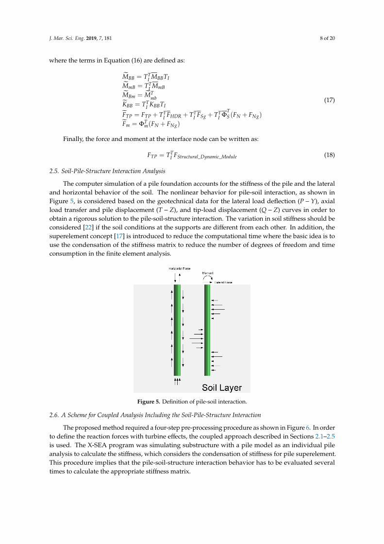
2.5. Soil-Pile-Structure Interaction Analysis
The computer simulation of a pile foundation accounts for the stiffness of the pile and the lateraland horizontal behavior of the soil. The nonlinear behavior for pile-soil interaction, as shown inFigure 5, is considered based on the geotechnical data for the lateral load deflection (P − Y), axialload transfer and pile displacement (T − Z), and tip-load displacement (Q − Z) curves in order toobtain a rigorous solution to the pile-soil-structure interaction. The variation in soil stiffness should beconsidered [22] if the soil conditions at the supports are different from each other. In addition, thesuperelement concept [17] is introduced to reduce the computational time where the basic idea is touse the condensation of the stiffness matrix to reduce the number of degrees of freedom and timeconsumption in the finite element analysis.
J. Mar. Sci. Eng. 2019, 6, x FOR PEER REVIEW 8 of 20
where the terms in Equation (16) are defined as:
( )
( )
TBB I BB I
TmB I mB
TBm mb
TBB I BB I
T T T TTP TP I HDR I Sg I S N Ng
Tm m N Ng
M T M TM T MM MK T K TF F T F T F T F F
F F F
=
=
=
=
= + + + Φ +
= Φ +
(17)
Finally, the force and moment at the interface node can be written as:
_ _T
TP I Structural Dynamic ModuleF T F= (18)
2.5. Soil-Pile-Structure Interaction Analysis
The computer simulation of a pile foundation accounts for the stiffness of the pile and the lateral and horizontal behavior of the soil. The nonlinear behavior for pile-soil interaction, as shown in Figure 5, is considered based on the geotechnical data for the lateral load deflection ( P Y− ), axial load transfer and pile displacement (T Z− ), and tip-load displacement (Q Z− ) curves in order to obtain a rigorous solution to the pile-soil-structure interaction. The variation in soil stiffness should be considered [22] if the soil conditions at the supports are different from each other. In addition, the superelement concept [17] is introduced to reduce the computational time where the basic idea is to use the condensation of the stiffness matrix to reduce the number of degrees of freedom and time consumption in the finite element analysis.
Figure 5. Definition of pile-soil interaction.
2.6. A Scheme for Coupled Analysis Including the Soil-Pile-Structure Interaction
The proposed method required a four-step pre-processing procedure as shown in Figure 6. In order to define the reaction forces with turbine effects, the coupled approach described in Section 2.1–2.5 is used. The X-SEA program was simulating substructure with a pile model as an individual pile analysis to calculate the stiffness, which considers the condensation of stiffness for pile superelement. This procedure implies that the pile-soil-structure interaction behavior has to be evaluated several times to calculate the appropriate stiffness matrix.
Figure 5. Definition of pile-soil interaction.
2.6. A Scheme for Coupled Analysis Including the Soil-Pile-Structure Interaction
The proposed method required a four-step pre-processing procedure as shown in Figure 6. In orderto define the reaction forces with turbine effects, the coupled approach described in Sections 2.1–2.5is used. The X-SEA program was simulating substructure with a pile model as an individual pileanalysis to calculate the stiffness, which considers the condensation of stiffness for pile superelement.This procedure implies that the pile-soil-structure interaction behavior has to be evaluated severaltimes to calculate the appropriate stiffness matrix.

J. Mar. Sci. Eng. 2019, 7, 181 9 of 20
J. Mar. Sci. Eng. 2019, 6, x FOR PEER REVIEW 9 of 20
Figure 6. Scheme for coupled analysis of turbine effects including pile-soil-structure interactions.
3. Numerical Example
3.1. Verification of Tripod Structures Supporting NREL 5MW Offshore Wind Turbines
The tripod support structure of a wind turbine, which was researched in NREL, was sitting on the seabed with a fixed boundary condition of 55 m long driven into a 45 m water depth, and extended 10 m above the mean sea level. This structure was modelled in the X-SEA program with external forces acquired from the hydrodynamic module in the FAST program. The water density is 1027 kg/m3, the significant wave height is 8 m, the wave period is 10 s and steady wind velocity is 8 m/s at a reference height of 90 m above the mean sea level. Based on the longest natural periods, the structure and the wave period, the analysis period was selected as the first 60 s, which should correspond to the start-up to power production and consists of both transient and steady behaviour. The support structure was modeled by using 158 nodes and 163 elements as illustrated in Figure 7. The geometry and material properties of the tripod structure are given in Table 1. The verification example focused on comparing six components of dynamic reaction forces and top-tower forces that resulted from FAST and from X-SEA coupled with the FAST program, as theoretically presented in Section 2 and Figures 3 and 4. The comparison was aimed at confirming that the X-SEA program could produce the same correct results as FAST.
Figure 6. Scheme for coupled analysis of turbine effects including pile-soil-structure interactions.
3. Numerical Example
3.1. Verification of Tripod Structures Supporting NREL 5MW Offshore Wind Turbines
The tripod support structure of a wind turbine, which was researched in NREL, was sitting on theseabed with a fixed boundary condition of 55 m long driven into a 45 m water depth, and extended10 m above the mean sea level. This structure was modelled in the X-SEA program with external forcesacquired from the hydrodynamic module in the FAST program. The water density is 1027 kg/m3, thesignificant wave height is 8 m, the wave period is 10 s and steady wind velocity is 8 m/s at a referenceheight of 90 m above the mean sea level. Based on the longest natural periods, the structure and thewave period, the analysis period was selected as the first 60 s, which should correspond to the start-upto power production and consists of both transient and steady behaviour. The support structure wasmodeled by using 158 nodes and 163 elements as illustrated in Figure 7. The geometry and materialproperties of the tripod structure are given in Table 1. The verification example focused on comparingsix components of dynamic reaction forces and top-tower forces that resulted from FAST and fromX-SEA coupled with the FAST program, as theoretically presented in Section 2 and Figures 3 and 4.The comparison was aimed at confirming that the X-SEA program could produce the same correctresults as FAST.

J. Mar. Sci. Eng. 2019, 7, 181 10 of 20J. Mar. Sci. Eng. 2019, 6, x FOR PEER REVIEW 10 of 20
Figure 7. Model of the NREL 5MW tripod support structure.
Table 1. Geometry and material properties of the tripod support structure.
Outer diameter of diagonal brace (m) 2.475–1.200 Wall thickness of diagonal brace (m) 0.035–0.025 Outer diameter of main tubular (m) 5.412–1.875 Wall thickness of main tubular (m) 0.05–0.035
Young's Modulus (N/m2) 2.1 × 10¹¹ Density (kg/m3) 7850
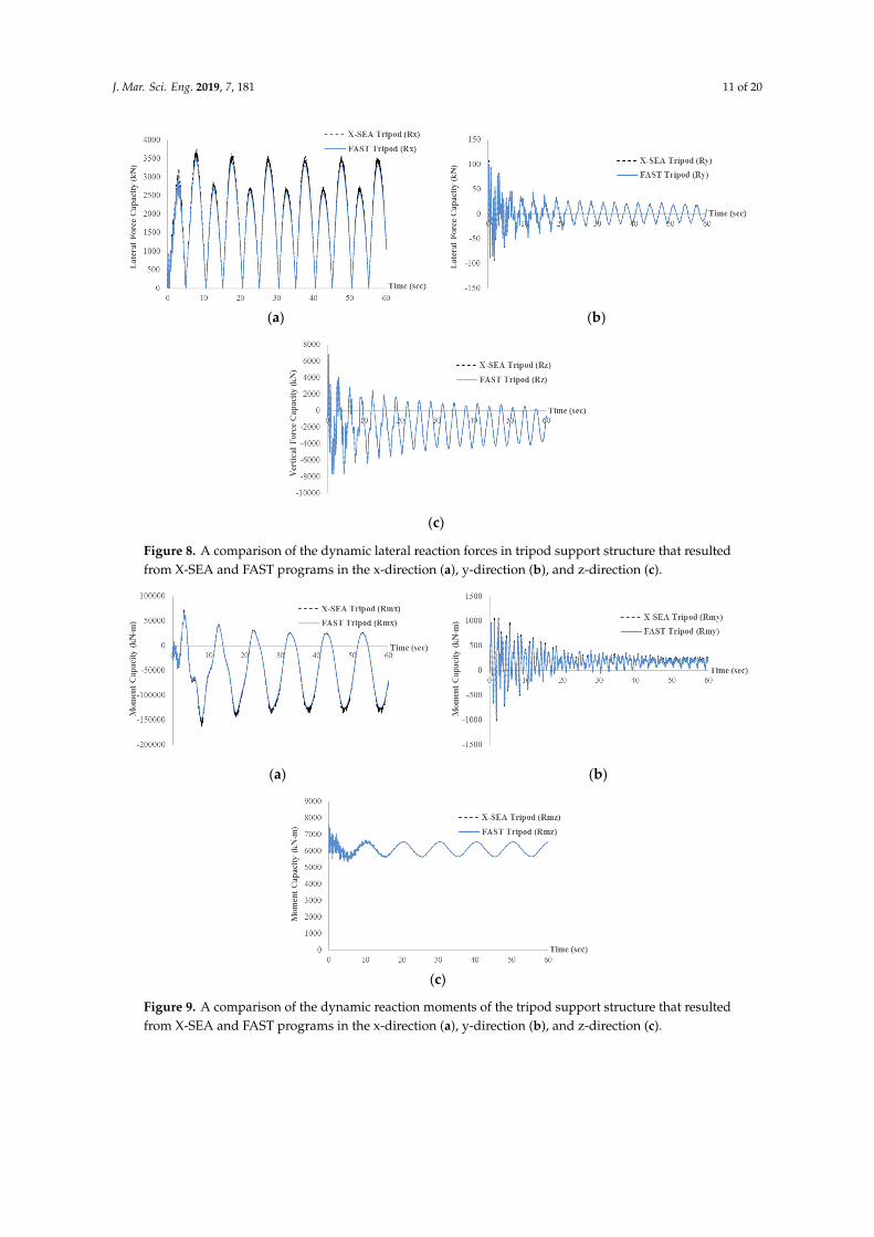
Figures 8 and 9 show that the six components of the reaction forces ( , ,x y zR R R ) and moments (, ,mx my mzR R R ) resulting from X-SEA are in good agreement with the corresponding results from FAST.
These responses, except for Rx, appear to be transient and significantly attenuated in the first 30 s and then become steady. Such initial transient behaviour is due to the small amount of damping in the structure and the method by which the hydrodynamic load and aerodynamic loading are initialized at the start of the simulation. Therefore, the transient responses are quickly damped out.
The marginal differences between the X-SEA and FAST results in Figures 8 and 9 can be attributed to the fact that the ratio of X-SEA/FAST obtained from the natural frequency of the six mode shapes are 0.99942, 0.99943, 0.99954, 0.99960, 0.99960 and 0.99944, respectively, as illustrated in Figure 10. The six dynamic components of the turbine load that were obtained by applying the X-SEA and FAST programs on the frame elements are identical, as shown in Figures 11 and 12. It can therefore be concluded that the present study program performs normally.
Figure 7. Model of the NREL 5MW tripod support structure.
Table 1. Geometry and material properties of the tripod support structure.
Outer diameter of diagonal brace (m) 2.475–1.200Wall thickness of diagonal brace (m) 0.035–0.025Outer diameter of main tubular (m) 5.412–1.875Wall thickness of main tubular (m) 0.05–0.035
Young’s Modulus (N/m2) 2.1 × 10¹¹
Density (kg/m3) 7850
Figures 8 and 9 show that the six components of the reaction forces (Rx, Ry, Rz) and moments(Rmx, Rmy, Rmz) resulting from X-SEA are in good agreement with the corresponding results from FAST.These responses, except for Rx, appear to be transient and significantly attenuated in the first 30 s andthen become steady. Such initial transient behaviour is due to the small amount of damping in thestructure and the method by which the hydrodynamic load and aerodynamic loading are initialized atthe start of the simulation. Therefore, the transient responses are quickly damped out.
The marginal differences between the X-SEA and FAST results in Figures 8 and 9 can be attributedto the fact that the ratio of X-SEA/FAST obtained from the natural frequency of the six mode shapesare 0.99942, 0.99943, 0.99954, 0.99960, 0.99960 and 0.99944, respectively, as illustrated in Figure 10.The six dynamic components of the turbine load that were obtained by applying the X-SEA and FASTprograms on the frame elements are identical, as shown in Figures 11 and 12. It can therefore beconcluded that the present study program performs normally.
J. Mar. Sci. Eng. 2019, 7, 181 11 of 20J. Mar. Sci. Eng. 2019, 6, x FOR PEER REVIEW 11 of 20
(a) (b)
(c)
Figure 8. A comparison of the dynamic lateral reaction forces in tripod support structure that resulted from X-SEA and FAST programs in the x-direction (a), y-direction (b), and z-direction (c).
(a) (b)
(c)
Figure 9. A comparison of the dynamic reaction moments of the tripod support structure that resulted from X-SEA and FAST programs in the x-direction (a), y-direction (b), and z-direction (c).
Figure 8. A comparison of the dynamic lateral reaction forces in tripod support structure that resultedfrom X-SEA and FAST programs in the x-direction (a), y-direction (b), and z-direction (c).
J. Mar. Sci. Eng. 2019, 6, x FOR PEER REVIEW 11 of 20
(a) (b)
(c)
Figure 8. A comparison of the dynamic lateral reaction forces in tripod support structure that resulted from X-SEA and FAST programs in the x-direction (a), y-direction (b), and z-direction (c).
(a) (b)
(c)
Figure 9. A comparison of the dynamic reaction moments of the tripod support structure that resulted from X-SEA and FAST programs in the x-direction (a), y-direction (b), and z-direction (c). Figure 9. A comparison of the dynamic reaction moments of the tripod support structure that resultedfrom X-SEA and FAST programs in the x-direction (a), y-direction (b), and z-direction (c).

J. Mar. Sci. Eng. 2019, 7, 181 12 of 20J. Mar. Sci. Eng. 2019, 6, x FOR PEER REVIEW 12 of 20
Figure 10. A comparison of natural frequency values of the tripod support structure resulting from the X-SEA and FAST programs.
Figure 11. Comparison of the dynamic top-tower forces in x, y, and z directions of the tripod support structure that resulted from the X-SEA and FAST programs.
Figure 12. Comparison of the dynamic top-tower moments about the x, y, and z directions of the tripod support structure between the X-SEA and FAST programs.
4.014.024.034.044.054.064.074.084.09
4.14.11
1 2 3 4 5 6
Freq
uenc
y (H
z)
Mode
X-SEA Frequency.FAST Frequency
-4000-3500-3000-2500-2000-1500-1000
-5000
5001000
0 10 20 30 40 50 60
Forc
e C
apac
ity (k
N) Time (s)
X-SEA Tripod (Fx)FAST Tripod (Fx)X-SEA Tripod (Fy)FAST Tripod (Fy)X-SEA Tripod (Fz)
-3000
-2000
-1000
0
1000
2000
3000
4000
0 10 20 30 40 50 60
Mom
ent C
apac
ity (k
N-m
)
Time (s)
X-SEA Tripod (Mx)FAST Tripod (Mx)X-SEA Tripod (My)FAST Tripod (My)X-SEA Tripod (Mz)FAST Tripod (Mz)
Figure 10. A comparison of natural frequency values of the tripod support structure resulting from theX-SEA and FAST programs.
J. Mar. Sci. Eng. 2019, 6, x FOR PEER REVIEW 12 of 20
Figure 10. A comparison of natural frequency values of the tripod support structure resulting from the X-SEA and FAST programs.
Figure 11. Comparison of the dynamic top-tower forces in x, y, and z directions of the tripod support structure that resulted from the X-SEA and FAST programs.
Figure 12. Comparison of the dynamic top-tower moments about the x, y, and z directions of the tripod support structure between the X-SEA and FAST programs.
4.014.024.034.044.054.064.074.084.09
4.14.11
1 2 3 4 5 6
Freq
uenc
y (H
z)
Mode
X-SEA Frequency.FAST Frequency
-4000-3500-3000-2500-2000-1500-1000
-5000
5001000
0 10 20 30 40 50 60
Forc
e C
apac
ity (k
N) Time (s)
X-SEA Tripod (Fx)FAST Tripod (Fx)X-SEA Tripod (Fy)FAST Tripod (Fy)X-SEA Tripod (Fz)
-3000
-2000
-1000
0
1000
2000
3000
4000
0 10 20 30 40 50 60
Mom
ent C
apac
ity (k
N-m
)
Time (s)
X-SEA Tripod (Mx)FAST Tripod (Mx)X-SEA Tripod (My)FAST Tripod (My)X-SEA Tripod (Mz)FAST Tripod (Mz)
Figure 11. Comparison of the dynamic top-tower forces in x, y, and z directions of the tripod supportstructure that resulted from the X-SEA and FAST programs.
J. Mar. Sci. Eng. 2019, 6, x FOR PEER REVIEW 12 of 20
Figure 10. A comparison of natural frequency values of the tripod support structure resulting from the X-SEA and FAST programs.
Figure 11. Comparison of the dynamic top-tower forces in x, y, and z directions of the tripod support structure that resulted from the X-SEA and FAST programs.
Figure 12. Comparison of the dynamic top-tower moments about the x, y, and z directions of the tripod support structure between the X-SEA and FAST programs.
4.014.024.034.044.054.064.074.084.09
4.14.11
1 2 3 4 5 6
Freq
uenc
y (H
z)
Mode
X-SEA Frequency.FAST Frequency
-4000-3500-3000-2500-2000-1500-1000
-5000
5001000
0 10 20 30 40 50 60
Forc
e C
apac
ity (k
N) Time (s)
X-SEA Tripod (Fx)FAST Tripod (Fx)X-SEA Tripod (Fy)FAST Tripod (Fy)X-SEA Tripod (Fz)
-3000
-2000
-1000
0
1000
2000
3000
4000
0 10 20 30 40 50 60
Mom
ent C
apac
ity (k
N-m
)
Time (s)
X-SEA Tripod (Mx)FAST Tripod (Mx)X-SEA Tripod (My)FAST Tripod (My)X-SEA Tripod (Mz)FAST Tripod (Mz)
Figure 12. Comparison of the dynamic top-tower moments about the x, y, and z directions of the tripodsupport structure between the X-SEA and FAST programs.
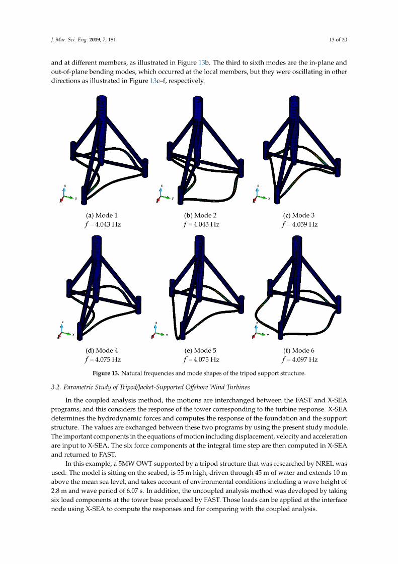
In the first mode, the tripod support structure was oscillating at the local members connectedto the pile head without considerable movement of the whole structure, as illustrated in Figure 13a.The second mode is the same as the first mode but the structure was oscillating in other directions
J. Mar. Sci. Eng. 2019, 7, 181 13 of 20
and at different members, as illustrated in Figure 13b. The third to sixth modes are the in-plane andout-of-plane bending modes, which occurred at the local members, but they were oscillating in otherdirections as illustrated in Figure 13c–f, respectively.
J. Mar. Sci. Eng. 2019, 6, x FOR PEER REVIEW 13 of 20
In the first mode, the tripod support structure was oscillating at the local members connected to the pile head without considerable movement of the whole structure, as illustrated in Figure 13a. The second mode is the same as the first mode but the structure was oscillating in other directions and at different members, as illustrated in Figure 13b. The third to sixth modes are the in-plane and out-of-plane bending modes, which occurred at the local members, but they were oscillating in other directions as illustrated in Figure 13c–f, respectively.
(a) Mode 1 f = 4.043 Hz
(b) Mode 2 f = 4.043 Hz
(c) Mode 3 f = 4.059 Hz
(d) Mode 4 f = 4.075 Hz
(e) Mode 5 f = 4.075 Hz
(f) Mode 6 f = 4.097 Hz
Figure 13. Natural frequencies and mode shapes of the tripod support structure.
3.2. Parametric Study of Tripod/Jacket-Supported Offshore Wind Turbines
In the coupled analysis method, the motions are interchanged between the FAST and X-SEA programs, and this considers the response of the tower corresponding to the turbine response. X-SEA determines the hydrodynamic forces and computes the response of the foundation and the support structure. The values are exchanged between these two programs by using the present study module. The important components in the equations of motion including displacement, velocity and acceleration are input to X-SEA. The six force components at the integral time step are then computed in X-SEA and returned to FAST.
In this example, a 5MW OWT supported by a tripod structure that was researched by NREL was used. The model is sitting on the seabed, is 55 m high, driven through 45 m of water and extends 10 m above the mean sea level, and takes account of environmental conditions including a wave height of 2.8 m and wave period of 6.07 s. In addition, the uncoupled analysis method was developed by
Figure 13. Natural frequencies and mode shapes of the tripod support structure.
3.2. Parametric Study of Tripod/Jacket-Supported Offshore Wind Turbines
In the coupled analysis method, the motions are interchanged between the FAST and X-SEAprograms, and this considers the response of the tower corresponding to the turbine response. X-SEAdetermines the hydrodynamic forces and computes the response of the foundation and the supportstructure. The values are exchanged between these two programs by using the present study module.The important components in the equations of motion including displacement, velocity and accelerationare input to X-SEA. The six force components at the integral time step are then computed in X-SEAand returned to FAST.
In this example, a 5MW OWT supported by a tripod structure that was researched by NREL wasused. The model is sitting on the seabed, is 55 m high, driven through 45 m of water and extends 10 mabove the mean sea level, and takes account of environmental conditions including a wave height of2.8 m and wave period of 6.07 s. In addition, the uncoupled analysis method was developed by takingsix load components at the tower base produced by FAST. Those loads can be applied at the interfacenode using X-SEA to compute the responses and for comparing with the coupled analysis.

J. Mar. Sci. Eng. 2019, 7, 181 14 of 20
The responses in the x-direction and y-direction of the tripod support structure that resulted fromthe coupled analysis are considerably smaller than the results of the uncoupled analysis, as plotted inFigures 14 and 15. This can be attributed to the fact that in the coupled models, the interaction betweenthe tower and support structures has been included in that results thanks to the additional couplingstiffness. This effectiveness of the coupled models in simulating more accurate responses has beenobserved in the dynamic analyses of jacket supported OWTs [21] and floating OWTs [29].
J. Mar. Sci. Eng. 2019, 6, x FOR PEER REVIEW 14 of 20
taking six load components at the tower base produced by FAST. Those loads can be applied at the interface node using X-SEA to compute the responses and for comparing with the coupled analysis.
The responses in the x-direction and y-direction of the tripod support structure that resulted from the coupled analysis are considerably smaller than the results of the uncoupled analysis, as plotted in Figures 14 and 15. This can be attributed to the fact that in the coupled models, the interaction between the tower and support structures has been included in that results thanks to the additional coupling stiffness. This effectiveness of the coupled models in simulating more accurate responses has been observed in the dynamic analyses of jacket supported OWTs [21] and floating OWTs [29].
Figure 14. Comparison of deflections in the x- direction resulting from couple and uncouple analyses.
Figure 15. Comparison of displacements in the y-direction resulting from coupled and uncoupled analyses.
3.3. Coupled Analysis of OWT Support Structures Including the Pile-Soil-Structure Interaction
The previous section demonstrated the accuracy of the responses of fixed support structures for OWTs by using coupled models and analyses. In this section, the tripod support structure that was researched by NREL, with its geometry and properties described in Figure 7 and Table 1 is used for
-0.005
0
0.005
0.01
0.015
0.02
0.025
0.03
0 10 20 30 40 50 60
Disp
lace
men
t (m
)
Time (Sec)
Coupled Analysis ( Ux )Uncoupled Analysis ( Ux )
-0.0025
-0.002
-0.0015
-0.001
-0.0005
0
0.0005
0.001
0.0015
0 10 20 30 40 50 60
Disp
lace
men
t (m
)
Time (Sec)
Coupled Analysis ( Uy )Uncoupled Analysis ( Uy )
Figure 14. Comparison of deflections in the x- direction resulting from couple and uncouple analyses.
J. Mar. Sci. Eng. 2019, 6, x FOR PEER REVIEW 14 of 20
taking six load components at the tower base produced by FAST. Those loads can be applied at the interface node using X-SEA to compute the responses and for comparing with the coupled analysis.
The responses in the x-direction and y-direction of the tripod support structure that resulted from the coupled analysis are considerably smaller than the results of the uncoupled analysis, as plotted in Figures 14 and 15. This can be attributed to the fact that in the coupled models, the interaction between the tower and support structures has been included in that results thanks to the additional coupling stiffness. This effectiveness of the coupled models in simulating more accurate responses has been observed in the dynamic analyses of jacket supported OWTs [21] and floating OWTs [29].
Figure 14. Comparison of deflections in the x- direction resulting from couple and uncouple analyses.
Figure 15. Comparison of displacements in the y-direction resulting from coupled and uncoupled analyses.
3.3. Coupled Analysis of OWT Support Structures Including the Pile-Soil-Structure Interaction
The previous section demonstrated the accuracy of the responses of fixed support structures for OWTs by using coupled models and analyses. In this section, the tripod support structure that was researched by NREL, with its geometry and properties described in Figure 7 and Table 1 is used for
-0.005
0
0.005
0.01
0.015
0.02
0.025
0.03
0 10 20 30 40 50 60
Disp
lace
men
t (m
)
Time (Sec)
Coupled Analysis ( Ux )Uncoupled Analysis ( Ux )
-0.0025
-0.002
-0.0015
-0.001
-0.0005
0
0.0005
0.001
0.0015
0 10 20 30 40 50 60
Disp
lace
men
t (m
)
Time (Sec)
Coupled Analysis ( Uy )Uncoupled Analysis ( Uy )
Figure 15. Comparison of displacements in the y-direction resulting from coupled anduncoupled analyses.
3.3. Coupled Analysis of OWT Support Structures Including the Pile-Soil-Structure Interaction
The previous section demonstrated the accuracy of the responses of fixed support structuresfor OWTs by using coupled models and analyses. In this section, the tripod support structure thatwas researched by NREL, with its geometry and properties described in Figure 7 and Table 1 is usedfor this parametric study. The environmental conditions are: 2.8 m wave height and 6.07 s waveperiod. Three models were investigated including the pile supported structure, pile superelement,and fixed support structure. The soil behavior is assumed to be nonlinear soil stiffness due to P−Y,T − Z, and Q − Z curves in the specified offshore design standards. The pile of 1.5 m diameter and0.05 m thickness penetrated the soil and embedded 55 m deep. The five soil layers with their soildata properties are listed in Figure 16. Another advanced technique introduced in this paper is the

J. Mar. Sci. Eng. 2019, 7, 181 15 of 20
condensation of the stiffness matrix to reduce the degree of freedom size and computational time inthe finite element analysis.
J. Mar. Sci. Eng. 2019, 6, x FOR PEER REVIEW 15 of 20
this parametric study. The environmental conditions are: 2.8 m wave height and 6.07 s wave period. Three models were investigated including the pile supported structure, pile superelement, and fixed support structure. The soil behavior is assumed to be nonlinear soil stiffness due to P Y− , T Z− , andQ Z− curves in the specified offshore design standards. The pile of 1.5 m diameter and 0.05 m thickness penetrated the soil and embedded 55 m deep. The five soil layers with their soil data properties are listed in Figure 16. Another advanced technique introduced in this paper is the condensation of the stiffness matrix to reduce the degree of freedom size and computational time in the finite element analysis.
Figure 16. The tripod support structure for pile-soil-structure interaction (PSSI) modeling.
One of the primary purposes of free vibration and dynamic analysis is to avoid the cases where a non-stationary load can resonate with the structural system when the structure is excited by a loading frequency close to a natural frequency of the system. Thus, a design chart provides the first to sixth mode shapes and the corresponding natural frequencies in Figures 17 and 18. A scaling factor of 25 was used to amplify the mode shapes and only the odd modes are displayed in Figures 17 and 18 since the even modes have the same frequencies that vibrate in the orthogonal planes.
In the first mode shape, the piled support structure is oscillating globally in the x-direction as a bending mode of the whole structure with a natural frequency of 3.521 Hz, as illustrated in Figure 18a. The second mode has a similar shape to the first mode and a natural frequency of 3.539 Hz. It oscillates in large movements in the x-direction as shown in Figure 18b while the third mode shape with a natural frequency of 3.848 Hz is oscillating in the opposite x-direction, as illustrated in Figure 18c. The fourth mode shape has natural frequencies of 3.857 Hz and the movement of a local member. which is connected to the pile head. This mode is oscillating in the negative x-direction as shown in Figure 18d. In the fifth and sixth mode shapes, the main tubular stays still and both of the local members, which are connected to the pile head, oscillate with frequencies of 4.005 Hz and 4.047 Hz, respectively, as illustrated in Figure 18e,f.
By comparing the natural frequencies that resulted from the fixed support structure model, it is seen that the natural frequencies resulting from the piled support structure model are increased 1.148, 1.142, 1.055, 1.057, 1.017, and 1.012 times as illustrated in Figure 17. These significant differences in natural frequency relate to the self-weight or mass and stiffness of the supporting pile and soils. The piled-support models were found to represent the tripod structure more realistically and to produce more accurate natural frequencies.
Figure 16. The tripod support structure for pile-soil-structure interaction (PSSI) modeling.
One of the primary purposes of free vibration and dynamic analysis is to avoid the cases where anon-stationary load can resonate with the structural system when the structure is excited by a loadingfrequency close to a natural frequency of the system. Thus, a design chart provides the first to sixthmode shapes and the corresponding natural frequencies in Figures 17 and 18. A scaling factor of 25was used to amplify the mode shapes and only the odd modes are displayed in Figures 17 and 18 sincethe even modes have the same frequencies that vibrate in the orthogonal planes.
In the first mode shape, the piled support structure is oscillating globally in the x-direction as abending mode of the whole structure with a natural frequency of 3.521 Hz, as illustrated in Figure 18a.The second mode has a similar shape to the first mode and a natural frequency of 3.539 Hz. It oscillatesin large movements in the x-direction as shown in Figure 18b while the third mode shape with anatural frequency of 3.848 Hz is oscillating in the opposite x-direction, as illustrated in Figure 18c.The fourth mode shape has natural frequencies of 3.857 Hz and the movement of a local member.which is connected to the pile head. This mode is oscillating in the negative x-direction as shownin Figure 18d. In the fifth and sixth mode shapes, the main tubular stays still and both of the localmembers, which are connected to the pile head, oscillate with frequencies of 4.005 Hz and 4.047 Hz,respectively, as illustrated in Figure 18e,f.
By comparing the natural frequencies that resulted from the fixed support structure model, itis seen that the natural frequencies resulting from the piled support structure model are increased1.148, 1.142, 1.055, 1.057, 1.017, and 1.012 times as illustrated in Figure 17. These significant differencesin natural frequency relate to the self-weight or mass and stiffness of the supporting pile and soils.The piled-support models were found to represent the tripod structure more realistically and to producemore accurate natural frequencies.

J. Mar. Sci. Eng. 2019, 7, 181 16 of 20J. Mar. Sci. Eng. 2019, 6, x FOR PEER REVIEW 16 of 20
Figure 17. The comparison of natural frequencies that resulted from the piled support structure model and the fixed support structure model.
(a) Mode 1
f = 3.521 Hz (b) Mode 2 f = 3.539 Hz
(c) Mode 3 f = 3.848 Hz
(d) Mode 4 f = 3.857 Hz
(e) Mode 5 f = 4.005 Hz
(f) Mode 6 f = 4.047 Hz
Figure 18. Natural frequencies and mode shapes resulting from the piled-supported structure model.
The displacements in the x-direction that resulted from the fixed support structure model and the piled support structure model are plotted in Figure 19. It can be noted that the piled support structure and pile superelement model produced responses 1.399 times more flexible that those of the fixed support structure model. It is important to note in Figure 20 that the displacements in y-
3.2
3.4
3.6
3.8
4
4.2
1 2 3 4 5 6
Freq
uenc
y ( H
z )
Mode
Piled Support StructureFixed Support Structure
Figure 17. The comparison of natural frequencies that resulted from the piled support structure modeland the fixed support structure model.
J. Mar. Sci. Eng. 2019, 6, x FOR PEER REVIEW 16 of 20
Figure 17. The comparison of natural frequencies that resulted from the piled support structure model and the fixed support structure model.
(a) Mode 1
f = 3.521 Hz (b) Mode 2 f = 3.539 Hz
(c) Mode 3 f = 3.848 Hz
(d) Mode 4 f = 3.857 Hz
(e) Mode 5 f = 4.005 Hz
(f) Mode 6 f = 4.047 Hz
Figure 18. Natural frequencies and mode shapes resulting from the piled-supported structure model.
The displacements in the x-direction that resulted from the fixed support structure model and the piled support structure model are plotted in Figure 19. It can be noted that the piled support structure and pile superelement model produced responses 1.399 times more flexible that those of the fixed support structure model. It is important to note in Figure 20 that the displacements in y-
3.2
3.4
3.6
3.8
4
4.2
1 2 3 4 5 6
Freq
uenc
y ( H
z )
Mode
Piled Support StructureFixed Support Structure
Figure 18. Natural frequencies and mode shapes resulting from the piled-supported structure model.
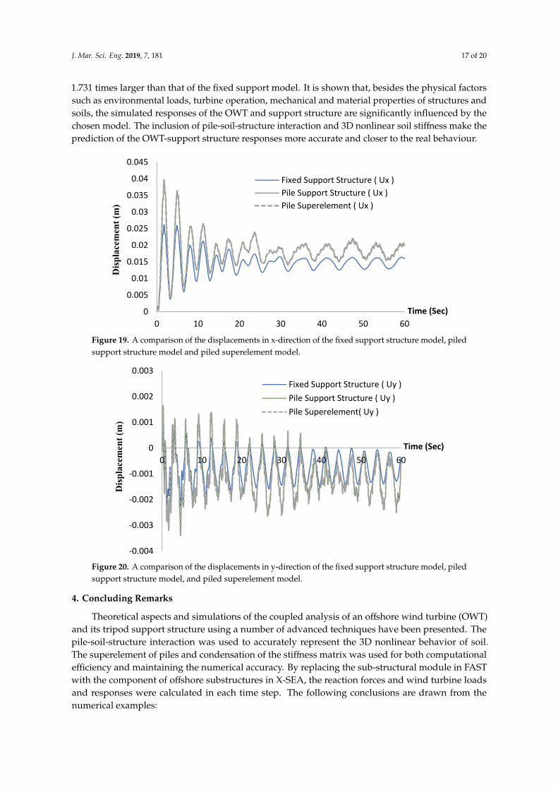
The displacements in the x-direction that resulted from the fixed support structure model and thepiled support structure model are plotted in Figure 19. It can be noted that the piled support structureand pile superelement model produced responses 1.399 times more flexible that those of the fixedsupport structure model. It is important to note in Figure 20 that the displacements in y-directionfrom both the piled support and superelement models have a similar trend in the x-direction but are
J. Mar. Sci. Eng. 2019, 7, 181 17 of 20
1.731 times larger than that of the fixed support model. It is shown that, besides the physical factorssuch as environmental loads, turbine operation, mechanical and material properties of structures andsoils, the simulated responses of the OWT and support structure are significantly influenced by thechosen model. The inclusion of pile-soil-structure interaction and 3D nonlinear soil stiffness make theprediction of the OWT-support structure responses more accurate and closer to the real behaviour.
J. Mar. Sci. Eng. 2019, 6, x FOR PEER REVIEW 17 of 20
direction from both the piled support and superelement models have a similar trend in the x-direction but are 1.731 times larger than that of the fixed support model. It is shown that, besides the physical factors such as environmental loads, turbine operation, mechanical and material properties of structures and soils, the simulated responses of the OWT and support structure are significantly influenced by the chosen model. The inclusion of pile-soil-structure interaction and 3D nonlinear soil stiffness make the prediction of the OWT-support structure responses more accurate and closer to the real behaviour.
Figure 19. A comparison of the displacements in x-direction of the fixed support structure model, piled support structure model and piled superelement model.
Figure 20. A comparison of the displacements in y-direction of the fixed support structure model, piled support structure model, and piled superelement model.
4. Concluding Remarks
Theoretical aspects and simulations of the coupled analysis of an offshore wind turbine (OWT) and its tripod support structure using a number of advanced techniques have been presented. The pile-soil-structure interaction was used to accurately represent the 3D nonlinear behavior of soil. The superelement of piles and condensation of the stiffness matrix was used for both computational efficiency and maintaining the numerical accuracy. By replacing the sub-structural module in FAST
0
0.005
0.01
0.015
0.02
0.025
0.03
0.035
0.04
0.045
0 10 20 30 40 50 60
Disp
lace
men
t (m
)
Time (Sec)
Fixed Support Structure ( Ux )Pile Support Structure ( Ux )Pile Superelement ( Ux )
-0.004
-0.003
-0.002
-0.001
0
0.001
0.002
0.003
0 10 20 30 40 50 60
Disp
lace
men
t (m
)
Time (Sec)
Fixed Support Structure ( Uy )Pile Support Structure ( Uy )Pile Superelement( Uy )
Figure 19. A comparison of the displacements in x-direction of the fixed support structure model, piledsupport structure model and piled superelement model.
J. Mar. Sci. Eng. 2019, 6, x FOR PEER REVIEW 17 of 20
direction from both the piled support and superelement models have a similar trend in the x-direction but are 1.731 times larger than that of the fixed support model. It is shown that, besides the physical factors such as environmental loads, turbine operation, mechanical and material properties of structures and soils, the simulated responses of the OWT and support structure are significantly influenced by the chosen model. The inclusion of pile-soil-structure interaction and 3D nonlinear soil stiffness make the prediction of the OWT-support structure responses more accurate and closer to the real behaviour.
Figure 19. A comparison of the displacements in x-direction of the fixed support structure model, piled support structure model and piled superelement model.
Figure 20. A comparison of the displacements in y-direction of the fixed support structure model, piled support structure model, and piled superelement model.
4. Concluding Remarks
Theoretical aspects and simulations of the coupled analysis of an offshore wind turbine (OWT) and its tripod support structure using a number of advanced techniques have been presented. The pile-soil-structure interaction was used to accurately represent the 3D nonlinear behavior of soil. The superelement of piles and condensation of the stiffness matrix was used for both computational efficiency and maintaining the numerical accuracy. By replacing the sub-structural module in FAST
0
0.005
0.01
0.015
0.02
0.025
0.03
0.035
0.04
0.045
0 10 20 30 40 50 60
Disp
lace
men
t (m
)
Time (Sec)
Fixed Support Structure ( Ux )Pile Support Structure ( Ux )Pile Superelement ( Ux )
-0.004
-0.003
-0.002
-0.001
0
0.001
0.002
0.003
0 10 20 30 40 50 60
Disp
lace
men
t (m
)
Time (Sec)
Fixed Support Structure ( Uy )Pile Support Structure ( Uy )Pile Superelement( Uy )
Figure 20. A comparison of the displacements in y-direction of the fixed support structure model, piledsupport structure model, and piled superelement model.
4. Concluding Remarks
Theoretical aspects and simulations of the coupled analysis of an offshore wind turbine (OWT)and its tripod support structure using a number of advanced techniques have been presented. Thepile-soil-structure interaction was used to accurately represent the 3D nonlinear behavior of soil.The superelement of piles and condensation of the stiffness matrix was used for both computationalefficiency and maintaining the numerical accuracy. By replacing the sub-structural module in FASTwith the component of offshore substructures in X-SEA, the reaction forces and wind turbine loadsand responses were calculated in each time step. The following conclusions are drawn from thenumerical examples:
J. Mar. Sci. Eng. 2019, 7, 181 18 of 20
• For the tripod structure itself, the first to sixth modes are oscillating at a local member connectedto the pile head. The sixth mode is the globally bending mode. The reaction forces and moments,natural frequencies and top-tower forces that resulted from X-SEA were in good agreement withthose that resulted from FAST.
• The physical interaction between the tower and support structure has been included in the coupledmodels as additional coupling stiffness, which results in considerably smaller responses comparedto the uncoupled models. This demonstrates that the coupled model should be used in the analysisand design of offshore wind turbine structures.
• For the piled-support tripod structures, the first to third modes are global whereas the fourth tosixth mode shapes are at a local member connected to the pile head. Their natural frequenciesare considerably larger than those of the fixed support model as the physical interactions andinfinite stiffness of the supporting pile-soil have been accounted for. This demonstrates the higheraccuracy and validity of the piled-support structure model.
• The piled-support model produces larger responses than the fixed support model but is identicalto the pile superelement model. Besides the physical factors, the simulation of OWT structures issignificantly influenced by the chosen model, because it needs condensed stiffness information forthe foundation base.
For future studies, physical models or measurements from real structures are recommended.The inclusion of 3D nonlinear soil stiffness into pile-soil-structure interaction would make the simulationmore accurate and realistic. Other approaches to modeling soil-structure interaction, especially theinclusion of soil damping where energy dissipates during vibration could be considered.
Author Contributions: Formal analysis, P.P.; investigation, P.P. and V.N.D.; Validation, P.P.; Conceptualization,V.N.D. and K.-D.K.; Methodology, V.N.D. and K.-D.K.; Writing—original draft preparation, P.P. and V.N.D.;Writing—review and editing, V.N.D. and K.-D.K.; Funding acquisition, K.-D.K.
Funding: This work is supported by Konkuk University, Seoul, Korea.
Conflicts of Interest: The authors declare no conflict of interest.
References
1. Esteban, M.D.; López-Gutiérrez, J.-S.; Negro, V. Gravity-based foundations in the offshore sector. J. Mar.Sci. Eng. 2019, 7, 64. [CrossRef]
2. Oh, K.-Y.; Nam, W.-C.; Ryu, M.-S.; Kim, J.-Y.; Epureanud, B.I. A review of foundations of offshore windenergy convertors: Current status and future perspectives. Renew. Sustain. Energy Rev. 2018, 88, 16–36.[CrossRef]
3. Ryu, M.S.; Kim, J.-Y.; Lee, J.-S. Comparison of two meteorological tower foundations for offshore windturbines. In Proceedings of the Twenty-Sixth International Offshore and Polar Engineering Conference,Rhodes, Greece, 26 June–2 July 2016.
4. Kim, S.-R.; Hung, L.C.; Oh, M. Group effect on bearing capacities of tripod bucket foundations in undrainedclay. Ocean Eng. 2014, 79, 1–9. [CrossRef]
5. Schaumann, P.; Böker, C. Can jackets and tripods compete with monopiles? In Proceedings of the CopenhagenOffshore Wind, Copenhagen, Denmark, 6–28 October 2005.
6. Zaaijer, M.B. Comparison of Monopile, Tripod, Suction Bucket and Gravity Base Design for a 6 MW Turbine; DelftUniversity of Technology: Delft, The Netherlands, 2003.
7. Ryu, M.S.; Kim, J.-Y.; Kang, K.-S. The first met-mast for offshore wind farm in Korea and its remote sensingsystem. In Proceedings of the Twenty-First International Offshore and Polar Engineering Conference, Maui,HI, USA, 19–24 June 2011.
8. Chen, D.; Huang, K.; Bretel, V.; Hou, L. Comparison of structural properties between monopile and tripodoffshore wind-turbine support structures. Adv. Mech. Eng. 2013, 5, 1–9. [CrossRef]
9. Hung, L.C.; Kim, S.-R. Evaluation of combined horizontal-moment bearing capacities of tripod bucketfoundations in undrained clay. Ocean Eng. 2014, 85, 100–109. [CrossRef]

J. Mar. Sci. Eng. 2019, 7, 181 19 of 20
10. Tran, N.X.; Hung, L.C.; Kim, S.-R. Evaluation of horizontal and moment bearing capacities of tripod bucketfoundations in sand. Ocean Eng. 2017, 140, 209–221. [CrossRef]
11. Yang, H.; Zhu, Y.; Lu, Q.; Zhang, J. Dynamic reliability based design optimization of the tripod sub-structureof offshore wind turbines. Renew. Energy 2015, 78, 16–25. [CrossRef]
12. Margariti, G.; Papadopoulos, A.; Barmpas, D.; Gantes, C.J.; Gkologiannis, C.P. Design of monopile andtripod foundation of fixed offshore wind turbines via advanced numerical analysis. In Proceedings of the8th GRACM International Congress on Computational Mechanics, Volos, Greece, 2–15 July 2015.
13. Hübler, C.; Hafele, J.; Gebhardt, C.G.; Rolfes, R. Experimentally supported consideration of operating pointdependent soil properties in coupled dynamics of offshore wind turbines. Mar. Struct. 2018, 57, 18–37.[CrossRef]
14. Häfele, J.; Hübler, C.; Gebhardt, C.G.; Rolfes, R. An improved two-step soil-structure interaction modelingmethod for dynamical analyses of offshore wind turbines. Appl. Ocean Res. 2016, 55, 141–150. [CrossRef]
15. Dinh, V.N.; McKeogh, E. Offshore Wind Energy: Technology Opportunities and Challenges. In Lecture Notesin Civil Engineering, Proceedings of the Vietnam Symposium on Advances in Offshore Engineering, Hanoi, Vietnam,25 September 2018; Springer: Singapore, 2018. [CrossRef]
16. Ong, M.C.; Bachynski, E.E.; Økland, O.D.; Passano, E. Dynamic responses of a jacket-type offshore windturbine using decoupled and coupled models. In Proceedings of the ASME 2014 33rd International Conferenceon Ocean, Offshore and Arctic Engineering (OMAE), San Francisco, CA, USA, 8–13 June 2014.
17. Voormeeren, S.N.; van der Valk, P.L.C.; Nortier, B.P.; Molenaar, D.-P.; Rixen, D.J. Accurate and efficientmodeling of complex offshore wind turbine support structures using augmented superelements. Wind Energy2014, 17, 1035–1054. [CrossRef]
18. Kim, K.D.; Plodpradit, P.; Manovachirasan, A.; Sinsabvarodom, C.; Kim, B.J. Analysis of offshore structuresfor wind turbines and oil and gas using X-SEA software. In Proceedings of the 11th World Congress onComputational Mechanics (WCCM XI), 5th European Conference on Computational Mechanics (ECCM V),6th European Conference on Computational Fluid Dynamics (ECFD VI), Barcelona, Spain, 20–25 July 2014.
19. Kim, K.-D.; Vachirapanyaku, S.; Plodpradit, P.; Dinh, V.-N.; Park, J.-H. Development of offshore structuralanalysis software X-SEA coupled with FAST. In Proceedings of the 38th International Conference on Ocean,Offshore & Artic Engineering, ASME 2019 OMAE 2019-96778, Glasgow, Scotland, UK, 9–14 June 2019.
20. Jonkman, J. FAST v8. National Renewable Energy Laboratory (NREL). USA, 2018. Available online:https://nwtc.nrel.gov/FAST8 (accessed on 19 September 2017).
21. Plodpradit, P.; Dinh, V.-N.; Kim, K.-D. Coupled analysis of offshore wind turbine jacket structures withpile-soil-structure interaction using FAST v8 and X-SEA. Appl. Sci. 2019, 9, 1633. [CrossRef]
22. Dinh, V.N.; Basu, B.; Brinkgreve, R.B.J. Wavelet-based evolutionary response of multi-span structuresincluding wave-passage and site-response effects. J. Eng. Mech. 2014, 140, 8. [CrossRef]
23. Failla, G.; Santangelo, F.; Foti, G.; Scali, F.; Arena, F. Response-spectrum uncoupled analyses for seismicassessment of offshore wind turbines. J. Mar. Sci. Eng. 2018, 6, 85. [CrossRef]
24. Basu, B.; Staino, A.; Dinh, V.N. Vibration of wind turbines under seismic excitations. In Proceedings of the5th Asian-Pacific Symposium on Structural Reliability and its Applications, Singapore, 23–25 May 2012.[CrossRef]
25. Fitzgerald, B.; Basu, B. A monitoring system for wind turbines subjected to combined seismic and turbulentaerodynamic loads. Struct. Monit. Maint. 2017, 4, 175–194. [CrossRef]
26. Kim, K.-D. X-SEA User Manual; Konkuk University: Seoul, Korea, 2016.27. Kim, K.D.; Suthasupradit, S.; Kim, Y.H.; Lomboy, G.R.; Dinh, V.N. New development of XFINAS software
for nonlinear dynamic and seismic analysis of structure. In Proceedings of the Third Asian-PacificCongress on Computational Mechanics (APCOM’07) & the Eleventh International Conference on theEnhancement and Promotion of Computational Methods in Engineering and Science (EPMESC XI), Kyoto,Japan, 3–6 December 2007.
28. Kim, B.J.; Plodpradit, P.; Kim, K.D.; Kim, H.G. Three-dimensional analysis of prestressed concrete offshorewind turbine structure under environmental and 5-MW turbine loads. J. Mar. Sci. Appl. 2018, 17, 625–637.[CrossRef]

J. Mar. Sci. Eng. 2019, 7, 181 20 of 20
29. Dinh, V.N.; Basu, B.; Nielsen, S.R.K. Impact of spar-nacelle-blade coupling on the edgewise response offloating offshore wind turbines. Coupled Syst. Mech. 2013, 2. [CrossRef]
30. Damiani, R.; Jonkman, J.; Hayman, G. SubDyn User’s Guide and Theory Manual; National Renewable EnergyLaboratory (NREL): Golden, CO, USA, March 2015.
© 2019 by the authors. Licensee MDPI, Basel, Switzerland. This article is an open accessarticle distributed under the terms and conditions of the Creative Commons Attribution(CC BY) license (http://creativecommons.org/licenses/by/4.0/).