triplex pump - files.pentairliterature.comfiles.pentairliterature.com/myers/ap-03-107.pdf · 2...
TRANSCRIPT

NOTE! To the installer: Please make sure you provide this manual to the owner of the equip ment or to the responsible party who maintains the system.
SC-35TRIPLEX PUMPINSTALLATION AND SERVICE MANUAL
Part # AP-03-107 | © 2018 Pentair plc | 02/21/18

2
SC-35 ENGINEERING DATAPower EndModel Triplex Pump SC-35
Maximum Input HP at Speed 50 at 625 rpm
Rated Continuous Plunger Load 4,800 lbs.
Stroke 2"
Maximum Rated Continuous Speed 625 rpm
Normal Continuous Speed Range 150 to 600 rpm
Minimum Speed 100 rpm
Oil Capacity 2 U.S. Quarts
Viscosity, S.S.U. at 210ºF 70 to 84
Power End Oiling System Splash
Power Frame, One Piece Cast Iron
Crosshead, Full Cylindrical Ductile Iron
Crosshead, Diameter x Length 2-1/2" x 2-1/2"
Crankshaft 4140 Heat Treated Forging
Crankshaft Diameters:At Drive ExtensionAt Tapered Roller BearingsAt Crankpin Bearings, Diameter x Length
1.375"1.752"2.373" x 1.945"
Crosshead (Wrist) Pin, Case-Hardened and Ground AISI 1018
Main Bearings Tapered Roller
Crankpin Bearings, Precision Automotive Babbitt-Lined
Extension (Pony) Rod 303 S.S.
Connecting Rod, Automotive Type Ductile Iron
Average Crosshead Speed:At 600 rpmAt 450 rpm
200 fpm150 fpm
Minimum Life Expectancy, Main Bearings, L10 10,000+hr
Liquid EndPiston Size Range, Diameter 2" thru 1-1/2"
Maximum Continuous Working Pressure 2,700 psi
Discharge Connection Size 1-1/4" NPTF
Suction Connection Size 2" NPTF
Available Liquid End Materials, ASTM:Ductile Iron A536 80-55-06
SC-35 ENGINEERING DATALiquid End (Continued)Piston Type HNBR & High
Strength Synthetic Fabric
Cylinder Liner, Field-Removable and Replaceable: Ceramic Coated416 S.S.
Valve Cover and Cylinder Head Plugs Carbon Steel
Retainer Plates Carbon Steel
Seals, Stuffing Boxes, Valve Covers, Cylinder Heads Buna-N
Bolting, High Strength, Heat Treated Alloy Steel
Valve Type, Abrasion Resistant 17-4PH S.S.
Valve Seat, Liquid Passage Areas .685 sq. in.
Average Liquid Velocity with 2" Pistons,Abrasion Resistant Valves:At 600 Crankshaft rpmAt 450 Crankshaft rpm
15.3 fps11.5 fps
Average Liquid Velocity at 600 rpm:Suction ManifoldDischarge Manifold
4.0 fps8.8 fps
GeneralOverall Dimensions:LengthWidthHeight
23-1/2"16-7/8"12-1/2"
Approximate Weights:With Ductile Iron Liquid End 250 lbs.
3
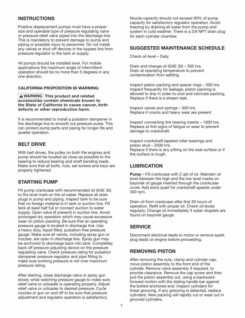
INSTRUCTIONS
Positive displacement pumps must have a proper size and operable type of pressure regulating valve or pressure relief valve piped into the discharge line. This is mandatory to prevent damage to pump and piping or possible injury to personnel. Do not install any valves or shut-off devices in the bypass line from pressure regulator to the tank or supply.
All pumps should be installed level. For mobile applications the maximum angle of intermittent operation should be no more than 5 degrees in any one direction.
CALIFORNIA PROPOSITION 65 WARNING:
This product and related accessories contain chemicals known to the State of California to cause cancer, birth defects or other reproductive harm.
It is recommended to install a pulsation dampener in the discharge line to smooth out pressure pulse. This can protect pump parts and piping for longer life and quieter operation.
BELT DRIVE
With belt drives, the pulley on both the engines and pump should be located as close as possible to the bearing to reduce bearing and shaft bending loads. Make sure that all bolts, nuts, set screws and keys are properly tightened.
STARTING PUMP
Fill pump crankcase with recommended oil (SAE 30) to the level mark on the oil saber. Replace all drain plugs in pump and piping. Inspect tank to be sure that no foreign material is in tank or suction line. Fill tank at least half full or connect suction to water supply. Open valve (if present) in suction line. Avoid prolonged dry operation which may cause excessive wear on piston packing. Be sure that an operating pressure gauge is located in discharge line. Use a heavy duty, liquid filled, pulsation-free pressure gauge. Make sure all valves, including spray gun or nozzles, are open in discharge line. Spray gun may be anchored to discharge back into tank. Completely back off pressure adjusting device on the pressure regulating valve. Check pressure rating for pulsation dampener pressure regulator and pipe fitting to make sure working pressure is not over maximum pressure rating.
After starting, close discharge valve or spray gun slowly while watching pressure gauge to make sure relief valve or unloader is operating properly. Adjust relief valve or unloader to desired pressure. Cycle nozzles or gun on and off to be sure that pressure adjustment and regulator operation is satisfactory.
Nozzle capacity should not exceed 90% of pump capacity for satisfactory regulator operation. Avoid freezing by draining all water from the pump and system in cold weather. There is a 3/8 NPT drain plug for each cylinder chamber.
SUGGESTED MAINTENANCE SCHEDULE
Check oil level – Daily
Drain and change oil (SAE 30) – 300 hrs. Drain at operating temperature to prevent contamination from settling.
Inspect piston packing and spacer rings – 500 hrs. Inspect frequently for leakage; piston packing is allowed to drip in order to cool and lubricate packing. Replace if there is a stream leak.
Inspect valves and springs – 500 hrs. Replace if cracks and heavy wear are present.
Inspect connecting link bearing inserts – 1000 hrs. Replace at first signs of fatigue or wear to prevent damage to crankshaft.
Inspect crankshaft tapered roller bearings and piston stud – 2000 hrs. Replace if there is any pitting on the seal surface or if the surface is rough.
LUBRICATION
Pump – Fill crankcase with 2 qts of oil. Maintain oil level between the high and the low level marks on bayonet oil gauge inserted through the crankcase cover. Add extra quart for crankshaft speeds under 300 rpm.
Drain oil from crankcase after first 30 hours of operation. Refill with proper oil. Check oil levels regularly. Change oil immediately if water droplets are found on bayonet gauge.
SERVICE
Disconnect electrical leads to motor or remove spark plug leads on engine before proceeding.
REMOVING PISTON
After removing the nuts, clamp and cylinder cap, move piston assembly to the front end of the cylinder. Remove valve assembly if required, to provide clearance. Remove the cap screw and then pull the piston assembly out, using a backward-forward motion with the sliding handle bar against the bolted-anchored end. Inspect cylinders for linear grooving. If any grooving is detected, replace cylinders. New packing will rapidly cut or wear out in grooved cylinders.
4
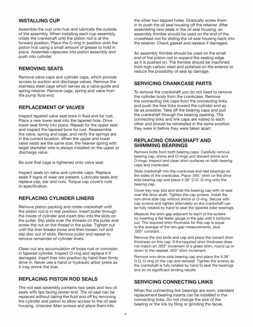
INSTALLING CUP
Assemble the cup onto hub and lubricate the outside of the assembly. When installing each cup assembly, rotate the crankshaft until the piston rod is at the forward position. Place the O-ring in position onto the piston hub using a small amount of grease to hold in place. Assemble capscrew into piston assembly and push into cylinder.
REMOVING SEATS
Remove valve caps and cylinder caps, which provide access to suction and discharge valves. Remove the stainless steel cage which serves as a valve guide and spring retainer. Remove cage, spring and valve from the pump fluid end.
REPLACEMENT OF VALVES
Inspect tapered valve seat bore in fluid end for rust. Place a new lower seat into the tapered hole. Drive lower seat firmly into place. Repeat for the upper seat and inspect the tapered bore for rust. Reassemble the valve, spring and cage, and verify the springs are in the correct location. When the upper and lower valve seats are the same size, the heavier spring with larger diameter wire is always installed on the upper or discharge valve.
Be sure that cage is tightened onto valve seat.
Inspect seals on valve and cylinder caps. Replace seals if signs of wear are present. Lubricate seals and replace cap, bar and nuts. Torque cap cover’s nuts to specification.
REPLACING CYLINDER LINERS
Remove piston packing and rotate crankshaft until the piston rod is in rear position. Insert puller through the inside of cylinder and insert disc into the slots on the puller. Slip plate over the threads on the puller and screw the nut on the thread in the puller. Tighten nut until the liner breaks loose and then loosen nut and slip disc out of slots. Remove puller and repeat to remove remainder of cylinder liners.
Clean out any accumulation of loose rust or corrosion in tapered cylinder. Inspect O-ring and replace it if damaged. Insert liner into position by hand then firmly drive in. Never use a hand or hydraulic arbor press as it may shrink the liner.
REPLACING PISTON ROD SEALS
The rod seal assembly contains two seals and two oil seals with lips facing power end. The oil seal can be replaced without taking the fluid end off by removing the cylinder and piston to allow access to the oil seal housing. Unscrew Allen screws and place them into
the other two tapped holes. Gradually screw them in to push the oil seal housing off the retainer. After assembling new seals in the oil seal housing, an assembly thimble should be used on the end of the crosshead rod for sliding the oil seal housing back into the retainer. Check gasket and replace if damaged.
An assembly thimble should be used on the small end of the piston rod to expand the sealing edge as it is pushed on. The thimble should be machined from high carbon steel and polished on the exterior to reduce the possibility of seal lip damage.
SERVICING CRANKCASE PARTS
To remove the crankshaft you do not need to remove the cylinder body from the crankcase. Remove the connecting link caps from the connecting links and push the free links toward the cylinder end as far as possible. Take off the bearing caps and pull the crankshaft through the bearing opening. The connecting links and link caps are mated to each other and should be reinstalled in the same position they were in before they were taken apart.
REPLACING CRANKSHAFT AND SHIMMING BEARINGSRemove bolts from both bearing caps. Carefully remove bearing cap, shims and O-rings and discard shims and O-rings. Inspect and clean shim surfaces on both bearing caps and crankcase.
Slide crankshaft into the crankcase and rest bearings on the sides of the crankcase. Place .045" shim on the drive side bearing cap and place 4.38" O.D. O-ring onto the bearing cap.
Cover key-way slot and slide the bearing cap with oil seal over the drive shaft. Tighten the cap screws. Install the non-drive side cap without shims or O-ring. Secure with cap screws and tighten alternately so the crankshaft can be fully rotated by hand to seat the tapered roller bearings.
Measure the shim gap adjacent to each of the screws by inserting a flat feeler gauge in the gap until it bottoms out. The required shim thickness for this cap is equal to the average of the two gap measurements, plus .005" constant.
Remove the two bolts and cap and place the correct shim thickness on this cap. If the required shim thickness does not match an .003" increment of a green shim, round up or down to the nearest .003" shim increment.
Remove non-drive side bearing cap and place the 4.38" O.D. O-ring on the cap and reinstall. Tighten the screws as the crankshaft is fully rotated by hand to seat the bearings and so no significant binding results.
SERVICING CONNECTING LINKS
When the connecting link bearings are worn, standard replacement bearing inserts can be installed in the connecting links. Do not change the size of the bearing or the link by filing or grinding the faces.
5
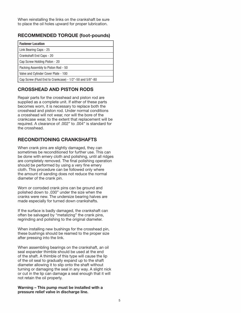
When reinstalling the links on the crankshaft be sure to place the oil holes upward for proper lubrication.
RECOMMENDED TORQUE (foot-pounds)
Fastener Location
Link Bearing Caps - 25
Crankshaft End Caps - 20
Cap Screw Holding Piston - 20
Packing Assembly to Piston Rod - 50
Valve and Cylinder Cover Plate - 100
Cap Screw (Fluid End to Crankcase) - 1/2"-50 and 5/8"-80
CROSSHEAD AND PISTON RODS
Repair parts for the crosshead and piston rod are supplied as a complete unit. If either of these parts becomes worn, it is necessary to replace both the crosshead and piston rod. Under normal conditions a crosshead will not wear, nor will the bore of the crankcase wear, to the extent that replacement will be required. A clearance of .002” to .004” is standard for the crosshead.
RECONDITIONING CRANKSHAFTS
When crank pins are slightly damaged, they can sometimes be reconditioned for further use. This can be done with emery cloth and polishing, until all ridges are completely removed. The final polishing operation should be performed by using a very fine emery cloth. This procedure can be followed only where the amount of sanding does not reduce the normal diameter of the crank pin.
Worn or corroded crank pins can be ground and polished down to .030” under the size when the cranks were new. The undersize bearing halves are made especially for turned down crankshafts.
If the surface is badly damaged, the crankshaft can often be salvaged by “metalizing” the crank pins, regrinding and polishing to the original diameter.
When installing new bushings for the crosshead pin, these bushings should be reamed to the proper size after pressing into the link.
When assembling bearings on the crankshaft, an oil seal expander thimble should be used at the end of the shaft. A thimble of this type will cause the lip of the oil seal to gradually expand up to the shaft diameter allowing it to slip onto the shaft without turning or damaging the seal in any way. A slight nick or cut in the lip can damage a seal enough that it will not retain the oil properly.
Warning – This pump must be installed with a pressure relief valve in discharge line.

6
THE PUMP MUST BE INSTALLED WITH A PRESSURE RELIEF VALVE IN DISCHARGE LINE
TROUBLESHOOTING Pump fails to build pressure with discharge closed Failure to hold pressure with discharge open Pump is noisy Pump gets hot Pressure gauge shows abnormal fluctuation Regulator chatter
POSSIBLE CAUSE OF PROBLEM 1. Pump not primed X 2. Valve closed in suction line X X 3. Suction line or sediment chamber clogged X X X 4. Air leak in suction line X X X 5. Pressure regulator valve badly worn or not properly adjusted X X 6. Pump packing or valves badly worn X X X 7. Pump cylinder body cracked X X X 8. Holes in discs are too large X 9. Need suction surge arrester X 10. Water in crankcase X 11. Worn connecting link bearings X X12. Lack of oil in crankcase X X13. Foaming mixture X X X14. Regulator plunger sticking X 15. Unloader stuffing box nut too tight X 16. Foreign matter under pump valve X X X17. Discharge surge arrester inoperative X X 18. Loose piston rod X19. Improper preload of crankshaft bearings X X
1. Pump priming is usually not necessary when the pump is installed correctly. However, there are certain conditions which may make it necessary to prime the pump to get the pumping action started. Priming will be required when it is impossible for the plunger to displace the air in the pump and replace it with water. This can be caused by a high suction lift, the valves being stuck on the seat or by valves sticking due to extreme corrosion. A pump will not prime readily if someone has tampered with the valve springs causing them to exert undue pressure of the valve plates against the valve seats.
2. A gate valve is sometimes installed in the suction line between a tank or pressure line and the pump sediment chamber. It will shut off the supply source in order to clean the sediment chamber or to perform pump repairs. If this valve is partially or fully closed, it will interfere with the flow of water to the pump suction. This may cause severe knocking and vibration of the pump because the water cannot flow into the cylinder cavities fast enough.
3. A sediment chamber should be installed in the suction line between the gate valve and the pump suction. The strainers in the sediment chambers are sufficient to allow a free flow of liquid to the pump. If the strainers become severely clogged, they will completely stop the flow of liquid to the pump.
4. Any plunger pump operating at a high pressure will not perform properly nor quietly if a mixture of air and water is allowed to enter the pump suction. A small air leak in the suction line will cause the pump to knock and vibrate excessively by allowing the pump to draw a certain amount of water mixed with air on each stroke of the piston. A large air leak will cause the pump to lose prime after which it cannot be reprimed until the air leak is stopped. Air leaks may occur at the joints of the suction line piping, at the gate valve in the suction line, at the gasket sealing the cap on the sediment chamber, by a crack in the suction wall of the cylinder body, or by air drawing past the packing on the suction stroke if the packing is badly worn.
Explanation of the Service Chart
7
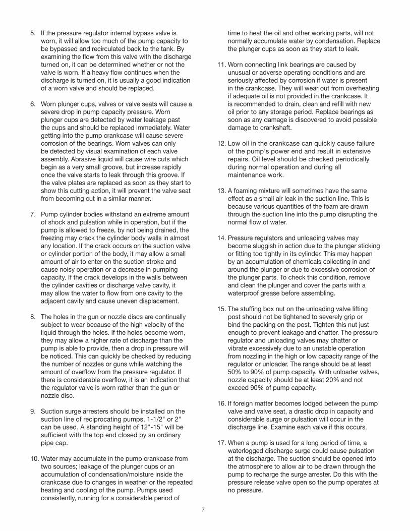
5. If the pressure regulator internal bypass valve is worn, it will allow too much of the pump capacity to be bypassed and recirculated back to the tank. By examining the flow from this valve with the discharge turned on, it can be determined whether or not the valve is worn. If a heavy flow continues when the discharge is turned on, it is usually a good indication of a worn valve and should be replaced.
6. Worn plunger cups, valves or valve seats will cause a severe drop in pump capacity pressure. Worn plunger cups are detected by water leakage past the cups and should be replaced immediately. Water getting into the pump crankcase will cause severe corrosion of the bearings. Worn valves can only be detected by visual examination of each valve assembly. Abrasive liquid will cause wire cuts which begin as a very small groove, but increase rapidly once the valve starts to leak through this groove. If the valve plates are replaced as soon as they start to show this cutting action, it will prevent the valve seat from becoming cut in a similar manner.
7. Pump cylinder bodies withstand an extreme amount of shock and pulsation while in operation, but if the pump is allowed to freeze, by not being drained, the freezing may crack the cylinder body walls in almost any location. If the crack occurs on the suction valve or cylinder portion of the body, it may allow a small amount of air to enter on the suction stroke and cause noisy operation or a decrease in pumping capacity. If the crack develops in the walls between the cylinder cavities or discharge valve cavity, it may allow the water to flow from one cavity to the adjacent cavity and cause uneven displacement.
8. The holes in the gun or nozzle discs are continually subject to wear because of the high velocity of the liquid through the holes. If the holes become worn, they may allow a higher rate of discharge than the pump is able to provide, then a drop in pressure will be noticed. This can quickly be checked by reducing the number of nozzles or guns while watching the amount of overflow from the pressure regulator. If there is considerable overflow, it is an indication that the regulator valve is worn rather than the gun or nozzle disc.
9. Suction surge arresters should be installed on the suction line of reciprocating pumps, 1-1/2" or 2" can be used. A standing height of 12"-15" will be sufficient with the top end closed by an ordinary pipe cap.
10. Water may accumulate in the pump crankcase from two sources; leakage of the plunger cups or an accumulation of condensation/moisture inside the crankcase due to changes in weather or the repeated heating and cooling of the pump. Pumps used consistently, running for a considerable period of
time to heat the oil and other working parts, will not normally accumulate water by condensation. Replace the plunger cups as soon as they start to leak.
11. Worn connecting link bearings are caused by unusual or adverse operating conditions and are seriously affected by corrosion if water is present in the crankcase. They will wear out from overheating if adequate oil is not provided in the crankcase. It is recommended to drain, clean and refill with new oil prior to any storage period. Replace bearings as soon as any damage is discovered to avoid possible damage to crankshaft.
12. Low oil in the crankcase can quickly cause failure of the pump's power end and result in extensive repairs. Oil level should be checked periodically during normal operation and during all maintenance work.
13. A foaming mixture will sometimes have the same effect as a small air leak in the suction line. This is because various quantities of the foam are drawn through the suction line into the pump disrupting the normal flow of water.
14. Pressure regulators and unloading valves may become sluggish in action due to the plunger sticking or fitting too tightly in its cylinder. This may happen by an accumulation of chemicals collecting in and around the plunger or due to excessive corrosion of the plunger parts. To check this condition, remove and clean the plunger and cover the parts with a waterproof grease before assembling.
15. The stuffing box nut on the unloading valve lifting post should not be tightened to severely grip or bind the packing on the post. Tighten this nut just enough to prevent leakage and chatter. The pressure regulator and unloading valves may chatter or vibrate excessively due to an unstable operation from nozzling in the high or low capacity range of the regulator or unloader. The range should be at least 50% to 90% of pump capacity. With unloader valves, nozzle capacity should be at least 20% and not exceed 90% of pump capacity.
16. If foreign matter becomes lodged between the pump valve and valve seat, a drastic drop in capacity and considerable surge or pulsation will occur in the discharge line. Examine each valve if this occurs.
17. When a pump is used for a long period of time, a waterlogged discharge surge could cause pulsation at the discharge. The suction should be opened into the atmosphere to allow air to be drawn through the pump to recharge the surge arrester. Do this with the pressure release valve open so the pump operates at no pressure.

8
18. Noisy pump operation can be caused by a loose plunger rod in the crosshead. This noise usually has a regular cadence timed with each stroke of the plunger. When this occurs, always replace both the rod and the crosshead.
19. Increased preload to the crankshaft bearings will reduce bearing life, require more power and generate more heat, while insufficient preload may cause a knock, timed with the crankshaft rotation. Check for loose bolts on the crankshaft end caps or adjust shims to obtain proper bearing preload.

9
MODEL SC-35
SECTION A-A
48
58 59 3150
49
56 53 52 67 38 19 27 29 1 144
24
26
3
21
2
28
39
5
30
25
18232017166636
35
33343244554751 3765
62
54
57
60
64
61
63
45
46
15
10
SECTION B-B
9
12
22
11
7
43
13
40
41
42
8 6
76
10
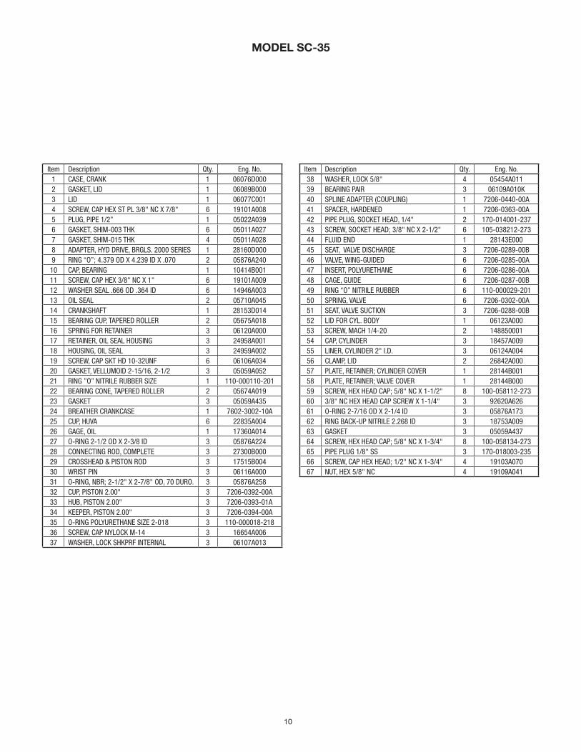
MODEL SC-35
Item Description Qty. Eng. No.1 CASE, CRANK 1 06076D000 2 GASKET, LID 1 06089B0003 LID 1 06077C0014 SCREW, CAP HEX ST PL 3/8" NC X 7/8" 6 19101A0085 PLUG, PIPE 1/2” 1 05022A0396 GASKET, SHIM-003 THK 6 05011A0277 GASKET, SHIM-015 THK 4 05011A0288 ADAPTER, HYD DRIVE, BRGLS. 2000 SERIES 1 28160D0009 RING “O”; 4.379 OD X 4.239 ID X .070 2 05876A240 10 CAP, BEARING 1 10414B00111 SCREW, CAP HEX 3/8" NC X 1" 6 19101A00912 WASHER SEAL .666 OD .364 ID 6 14946A00313 OIL SEAL 2 05710A04514 CRANKSHAFT 1 28153D01415 BEARING CUP, TAPERED ROLLER 2 05675A01816 SPRING FOR RETAINER 3 06120A00017 RETAINER, OIL SEAL HOUSING 3 24958A00118 HOUSING, OIL SEAL 3 24959A00219 SCREW, CAP SKT HD 10-32UNF 6 06106A03420 GASKET, VELLUMOID 2-15/16, 2-1/2 3 05059A05221 RING ”O” NITRILE RUBBER SIZE 1 110-000110-20122 BEARING CONE, TAPERED ROLLER 2 05674A01923 GASKET 3 05059A43524 BREATHER CRANKCASE 1 7602-3002-10A25 CUP, HUVA 6 22835A00426 GAGE, OIL 1 17360A01427 O-RING 2-1/2 OD X 2-3/8 ID 3 05876A22428 CONNECTING ROD, COMPLETE 3 27300B00029 CROSSHEAD & PISTON ROD 3 17515B00430 WRIST PIN 3 06116A00031 O-RING, NBR; 2-1/2" X 2-7/8" OD, 70 DURO. 3 05876A25832 CUP, PISTON 2.00" 3 7206-0392-00A33 HUB, PISTON 2.00" 3 7206-0393-01A34 KEEPER, PISTON 2.00" 3 7206-0394-00A35 O-RING POLYURETHANE SIZE 2-018 3 110-000018-21836 SCREW, CAP NYLOCK M-14 3 16654A00637 WASHER, LOCK SHKPRF INTERNAL 3 06107A013
Item Description Qty. Eng. No.38 WASHER, LOCK 5/8" 4 05454A01139 BEARING PAIR 3 06109A010K40 SPLINE ADAPTER (COUPLING) 1 7206-0440-00A41 SPACER, HARDENED 1 7206-0363-00A42 PIPE PLUG, SOCKET HEAD, 1/4" 2 170-014001-23743 SCREW, SOCKET HEAD; 3/8" NC X 2-1/2" 6 105-038212-27344 FLUID END 1 28143E00045 SEAT, VALVE DISCHARGE 3 7206-0289-00B46 VALVE, WING-GUIDED 6 7206-0285-00A47 INSERT, POLYURETHANE 6 7206-0286-00A48 CAGE, GUIDE 6 7206-0287-00B49 RING “O” NITRILE RUBBER 6 110-000029-20150 SPRING, VALVE 6 7206-0302-00A51 SEAT, VALVE SUCTION 3 7206-0288-00B52 LID FOR CYL. BODY 1 06123A00053 SCREW, MACH 1/4-20 2 14885000154 CAP, CYLINDER 3 18457A00955 LINER, CYLINDER 2" I.D. 3 06124A00456 CLAMP, LID 2 26842A00057 PLATE, RETAINER; CYLINDER COVER 1 28144B00158 PLATE, RETAINER; VALVE COVER 1 28144B00059 SCREW, HEX HEAD CAP; 5/8" NC X 1-1/2" 8 100-058112-27360 3/8" NC HEX HEAD CAP SCREW X 1-1/4" 3 92620A62661 O-RING 2-7/16 OD X 2-1/4 ID 3 05876A17362 RING BACK-UP NITRILE 2.268 ID 3 18753A00963 GASKET 3 05059A43764 SCREW, HEX HEAD CAP; 5/8" NC X 1-3/4" 8 100-058134-27365 PIPE PLUG 1/8" SS 3 170-018003-23566 SCREW, CAP HEX HEAD; 1/2" NC X 1-3/4" 4 19103A07067 NUT, HEX 5/8" NC 4 19109A041

11
THIS PAGE INTENTIONALLY LEFT BLANK

1101 MYERS PARKWAY ASHLAND, OHIO, USA 44805 855-274-8948
WWW.FEMYERS.COM
Warranty Rev. 01/18
STANDARD LIMITED WARRANTYCENTRIFUGAL & RECIPROCATING PUMPS
Pentair Myers® morf shtnom 21 fo doirep a rof pihsnamkrow dna lairetam ni stcefed tsniaga stcudorp sti stnarraw the date of shipment from Pentair Myers or 18 months from the manufacturing date, whichever occurs first – provided that such products are used in compliance with the requirements of the Pentair Myers catalog and technical manuals.
During the warranty period and subject to the conditions set forth, Pentair Myers, at its discretion, will repair or replace to the original user, the parts that prove defective in materials and workmanship. Pentair Myers reserves the right to change or improve its products or any portions thereof without being obligated to provide such a change or improvement for prior sold and/or shipped units.
Seals, piston cups, packing, plungers, liners and valves used for handling clear, fresh, nonaerated water at a temperature not exceeding 120ºF are warranted for ninety days from date of shipment. All other applications are subject to a thirty day warranty. Accessories such as motors, engines and auxiliary equipment are warranted by the respective manufacturer and are excluded in this standard warranty. Under no circumstance will Pentair Myers be responsible for the cost of field labor, travel expenses, rented equipment, removal/reinstallation costs or freight expenses to and from the factory or an authorized Pentair Myers service facility.
This limited warranty will not apply: (a) to defects or malfunctions resulting from failure to properly install, operate or maintain the unit in accordance with the printed instructions provided; (b) to failures resulting from abuse, accident or negligence; (c) to normal maintenance services and parts used in connection with such service; (d) to units that are not installed in accordance with applicable local codes, ordinances and good trade practices; (e) if the unit is moved from its original installation location; (f) if unit is used for purposes other than for what it is designed and manufactured; (g) to any unit that has been repaired or altered by anyone other than Pentair Myers or an authorized Pentair Myers service provider; (h) to any unit that has been repaired using non factory specified/OEM parts.
Warranty Exclusions: PENTAIR MYERS MAKES NO EXPRESS OR IMPLIED WARRANTIES THAT EXTEND BEYOND THE DESCRIPTION ON THE FACE HEREOF. PENTAIR MYERS SPECIFICALLY DISCLAIMS THE IMPLIED WARRANTIES OF MERCHANTABILITY AND FITNESS FOR ANY PARTICULAR PURPOSE.
Liability Limitation: IN NO EVENT SHALL PENTAIR MYERS BE LIABLE OR RESPONSIBLE FOR CONSEQUENTIAL, INCIDENTAL OR SPECIAL DAMAGES RESULTING FROM OR RELATED IN ANY MANNER TO ANY PENTAIR MYERS PRODUCT OR PARTS THEREOF. PERSONAL INJURY AND/OR PROPERTY DAMAGE MAY RESULT FROM IMPROPER INSTALLATION. PENTAIR MYERS DISCLAIMS ALL LIABILITY, INCLUDING LIABILITY UNDER THIS WARRANTY, FOR IMPROPER INSTALLATION. PENTAIR MYERS RECOMMENDS INSTALLATION BY PROFESSIONALS.
Some states do not permit some or all of the above warranty limitations or the exclusion or limitation of incidental or consequential damages and therefore such limitations may not apply to you. No warranties or representations at any time made by any representatives of Pentair Myers shall vary or expand the provision hereof.