triple-layer membrane structures
TRANSCRIPT

Triple-layer membrane structuresSound insulation performance and practical solutions
MSc-thesis26-08-2011
Made by: J.J.E. de Vries
In collaboration with
Zéni
th M
usic
al h
all,
Stra
ssbo
urg
[Imag
e c
ourt
esy
of W
ayfa
ring
Trav
el G
uide
]


In collaboration with:
Delft University of TechnologyFaculty of Civil Engineering and Geo Sciences
Peutz bv, Zoetermeer
Tentech bv, Utrecht
MSc-thesis26-08-2011
Made by: J.J.E. de Vries*
Triple-layer membrane structuresSound insulation performance and practical solutions
Abstract
This report describes a Master’s Thesis research that has been carried out to gain insight in the possible improvements of sound insulation of membrane structures, which are used in practice for temporary structures, e.g. festival tents, and to give practical solutions. This research concentrated on triple-leaf membrane systems with filled cavities. From a state-of-the-art review can be concluded that triple-leaf membrane systems, when filled, perform better than double-leaf and single-leaf membrane structures. From literature re-search it was concluded as well that tension in the membrane has a negligible effect on the sound insulation and that, on the other hand the flow resistance both of the filling and of the membrane material has large influence. Three different kind of filling materials were used in the present study: (lightweight) glass wool, polyester wool and aerogel. Acoustical measurements were carried out in a laboratory, of which the outcomes were compared to a number of computer and mathematical models. The Multiple Layer Model appears to give good prediction for filled triple-layer membrane systems and this model therefore was used to optimise the important parameters. A well performing triple-layer membrane system was discussed, which met the restriction of 7kg/m2 for the surface density of the membrane package. This system includes one layer of aerogel for reasonable sound insula-tion at low frequencies, and one thicker layer of glass wool yielding good sound insulation at higher frequencies. This system is only investigated theoretically and not empirically (yet). Details have been worked out for a number of practical membrane structure ap-plications for this result (also applicable to variants using only glass wool), focussing on temporary (festival) tent structures.
Keywords: sound insulation; membrane; triple-leaf membrane; aerogel; practical solutions
* Corresponding author. Tel: +31 6 16526409E-mail: [email protected] address: Van Merlenstraat 114, The Hague, The Netherlands


Preface
In the specialization Building Physics from the master Building Engineering, acoustics have always been the subject interesting me the most. It fascinates me how acoustics can be so important in everyday life and still so elusive. When I came in contact with the development in the art of special structures the architect inside me came up. I knew right away that I wanted to investigate the acoustic performance of a certain type of special structure; the membrane/tent structure. Also right away, I realized that the fabric used for these membrane structures is very lightweight so improving the acoustic performance (on absorption and transmission level) would be a huge challenge.
For helping me get trough this thesis, thanks go out to my graduation committee, which consists of the following members:
Prof. Ir. R. NijsseProfessor at the faculties of Civil Engineering and Architecture, TU Delft
Ir. H.R. SchipperSection Building Engineering, Civil Engineering, TU Delft
Dr. Ir. Arch. M.J. TenpierikSection Climate Design, chair Building Physics, Architecture, TU Delft
Ing. M.R. LautenbachPeutz bv, Zoetermeer
Ir. R. HoutmanTentech bv, Utrecht
I would also like to thank Mathis Chlosta, Theo Scheers, Jorrit Konings, Hayo Hendrikse, Marleen Keijzer, Harmen Werkman, Henriëtte de Ruiter, my girlfriend Odiel, my parents (Bert and Carla) and brother (Ingmar), for their contribution and/or support, whether it was a lot or a little.
And off course the people from Verseidag and Mermet and Michael O’Connor from Aspen Aerogels for providing the materials I needed for this research free of charge.
Jesse J.E. de Vries


Table of contents
List of Symbols
1 Introduction
1.1 Research objective 1.2 Research question 1.3 Approach 1.4 Time Schedule
2 Acoustic theory
2.2 Room acoustics 2.2.1 Sound reflection 2.2.2 Diffuse sound field 2.2.3 Reverberation and steady-state density 2.2.4 Sound absorption and absorbers 2.3 Sound insulation 2.3.1 Direct airborne sound transmission 2.3.2 Multiple Layer Model References
3 Acoustic properties of membranes - State-of-the-art review
3.1 Absorption and reflection coefficients 3.1.1 Single-leaf systems 3.1.2 Double-leaf systems 3.2 Sound insulation aspects 3.2.1 Small additional weights 3.2.2 Noise barriers 3.2.3 Research in France 3.2.4 Triple-leaf systems 3.3 Contex-T research project 3.4 Example projects 3.4.1 Suvarnabhumi International Airport, Bangkok 3.4.2 Cultural Centre, Puchheim 3.4.3 Skyscrape auditorium, London 3.4.4 Petrus- and Paulus church, Maassluis (NL) References
4 Membrane structures - Philosophy, engineering and material
4.1 Form, structure and design 4.1.1 The concept 4.1.2 Primary structures 4.1..3 Membrane engineering
10
13
15151617
21
212121222225263638
41
414246515356586062636464656666
69
69707072

4.1.4 Details 4.2 The material 4.2.1 Material types, qualities and characteristics 4.3 New developments 4.3.1 Acoustics 4.3.2 Other special materials 4.4 Example projects 4.4.1 Airship hangar, Brand, Germany 4.4.2 Eden Project, Cornwall, UK 4.4.3 Millenium Dome, London, UK 4.4.4 Khan Shatyr Entertainment Centre, Astana, Kazakhstan References
5 Improvement strategies and concepts
5.1 Basis, based on literature 5.2 Improvement strategies 5.2.1 Type of leaf material 5.2.2 Other membrane-related options 5.2.3 Type of cavity filling material 5.2.4 Transmission loss by friction 5.3 Concepts 5.3.1 Variants 5.3.2 Cavity thickness References
6 Measurements and results
6.1 Standards and guidelines 6.2 The investigated construction 6.2.1 The investigated membrane types 6.3 Measurements 6.3.1 Measurement method 6.3.2 Accuracy 6.3.3 Environment conditions 6.3.4 Results References
7 Theoretical validation
7.1 Single layer membranes 7.2 Triple layer membranes 7.2.1 Multiple Layer Model 7.2.2 Conventional formula for triple-leaf systems 7.2.3 Sakagami’s triple-leaf model 7.2.4 Discussion and conclusion for the triple-leaf systems 7.3 Triple-leaf membranes versus double-layer membranes References
747475818181828383848586
89
89898990909393949698
101
101101102103103104105105111
113
113116117117117118123124

127
127128128129132134135137137138138140144144145146
149150
8 Optimisation and practical solutions
8.1 Problem definition 8.1.1 Room acoustical point of view 8.2 Passive solutions 8.2.1 Solutions with respect to the filling material 8.2.2 Solutions with respect to the membrane 8.2.3 Solutions with respect to the cavity 8.2.4 Hybrid solutins 8.2.5 Pneumatic structures 8.3 Active solutions 8.4 Assembly and details 8.4.1 Assembly procedure 8.4.2 Details 8.5 Other aspects 8.5.1 Building physics aspects 8.5.2 Other membrane construction related aspects References
9 Conclusions and recommendations Recommendations

List of symbols
Plate dimensionPlate dimensionVelocity of sound in airBending phase velocityPhase velocity of longitudinal wavesFrequencyCritical frequencyResonance frequencyPlate dimension (height) Wave number Plate dimension (length)MassPorositySound pressureReflection coefficient, airflow resistivityDynamic (spring) stiffness(plate) thicknessSound particle velocityTotal energy density, plate dimension (width)Potential energy densityKinetic energy density
Absorption area, acoustic admittancePermeabilityWaterhouse correctionSound Energy, Young’s modulusSound IntensityMass (weight)Quality factorReflection factor, airflow resistance, (airborne) sound insulationRadiation resistanceSpecific airflow resistanceRoom surface/areaTemperature, temporal period, Reverberation timeCircumferenceVolume(Sound) powerRadiated sound powerSpecific acoustic impedanceNormal acoustic surface impedanceCharacteristic impedance of air
Absorption coefficientAdiabatic constantWave lengthPhase angle of specific impedance, coefficient of viscosity
abcocbclffcf0h ikl mnpr stuwwpotwkin
ABCwEIM QARRrRsSTUVWWradZa,sZa,nZ0
mmm s-1
m s-1
m s-1
HzHzHzm
Radians m-1
mKg m-2
-Pa = N m-2
-, Pa s m-2 = Ns m-3
N m-3
m m s-1
J m-3, mJ m-3
J m-3
m2 , -m2
dBJ, N m-2
W m-2
kg--, Pa s m-3 , dBKg radians m-1
Pa s m-1
m2
oC, s, smm3
WW-Kg m-2 s-1 = Pa s m-1
Kg m-2 s-1 = Pa s m-1
--m-, -
−1
αγλµ

Poisson’s ratioLoss factorAngle of incidenceDensity of airRadiation factor/efficiencyAngular frequencyAngular resonance frequencySquare root of
--RadiansKg m-3
-Radians s-1
Radians s-1
-
νηθρ0σωω0χ f fc


13
Due to the recent developments in membrane-construction techniques, the amount of pro-jects using membrane fabrics has increased. Structures ranging from stadiums to music halls and from festival tents to big span structures, membranes are becoming increasingly normal. Most of the time though, membrane is only applied as (part of) a roof or canopy. On the other hand, an increase in membrane use for acoustical absorbers and reflectors can be seen to improve the acoustic quality of a room, auditorium, etc. These are applied in the already existing room and are usually cavity-backed; filled with an absorptive ma-terial or air. Another development originated in Germany, where research is ongoing into inflatable membrane or foil based noise barriers for all kinds of applications, such as temporary noise reduction around building sites and all kinds of noise prevention. In order to de-termine whether these membrane noise barriers have the same, or even better, acoustic performances, knowledge about the acoustic properties of membranes is required.
In this thesis, research is described on the acoustic performance of membrane structures. Two aspects are important when talking about the “acoustic performance”: absorption properties (room acoustics) and transmission properties (sound insulation). The empha-sis in this thesis is on sound insulation, but to gain full knowledge on the subject, the the-ory of absorption had to be studied as well. Some restrictions and factors of importance in this matter are: the entire envelope has to be closed (no sound leaks), the noise resulting from rain or all other impact noise is not dealt with and in this thesis only airborne sound insulation (not structure-borne either) is studied. Reviewing the already done research on the subject shows that single-leaf membrane does not act well as a sound insulator and thus the emphasis in the present research is on double- and triple- leaf membrane systems.
Introduction 1
Fig. 1.1 The airship hangar in Brand, Germany [Image courtesy of Koch]

14
INTRODUCTION
Some theory on general acoustics in relation to absorption and especially sound insula-tion is presented in chapter 2. Chapter 3 addresses the research already been done on membrane structures in relation to sound insulation and in a smaller degree to sound absorption. This chapter can be seen as a state-of-the-art review on this thesis’ subject.
A “membrane-structure building” is a building in which active use is made of the cha-racteristics of membrane materials. A membrane is a flexible building component that is stabilised under tension only. Some examples of membrane structures can be seen in figu-res 1.1-4. Chapter 4 discusses all relevant theory on membrane building and the material.
Conclusions from both the state-of-the-art review as well as from chapter 4 are described in chapter 5 and a system of triple-layer membranes is adopted from there on. A number
of membrane configurations are introduced, which can be divided into two categories: the first categories has a permeable leaf on sound incidence side in order to gain some ab-sorption and create a better room acoustical environment; the second categories however has three impermeable membranes and will theoretically perform better in relation to sound insulation.
Above fact has been proven by doing measurements on the above mentioned membrane configurations in an acoustic laboratory. Three different filling materials were selected from a wide range of available materials: (lightweight) glass wool, polyester wool and aerogel. The measurement results are shown and discussed in chapter 6. With a view to completeness and a better understanding of membrane behaviour, some single-leaf sound insulation measurements were carried out as well.
In chapter 7, the measurement results are compared to a computational model available on the Delft University of Technology, general acoustic theory and models presented in earlier research studies. The first model describes the measurements quite well as for the triple-leaf membrane systems, and in chapter 8 some important parameters are discussed and optimised using, the theoretical model. The simple mass law for oblique incidence predicts the results for single-leaf systems well.
Fig. 1.2 The Khan Shatyr Enter-tainment Centre in Antara, Ka-zakhstan, from Foster+Partners [Image courtesy of Richard Orange]

15
RESEARCH QUESTION
Since this research also focusses on practical solutions, chapter 8 presents some practical restrictions and benefits of a triple-leaf membrane system. A couple of typical (usually permanent) membrane structures are described and detailed, but the emphasis lies on the temporary building of (festival) tent structures, especially on the detailing in relation to any sound leaks.
1.1 Research objectiveThe research objective can be split into two different parts; the room acoustics per-formance and the sound insulation performance. The emphasis in this thesis is on the sound insulation performance. This is due to the fact that research on this matter is still ongoing and no final (practical) solution has been found yet, whereas a sound insulation effective membrane system can be used in a construction as a roof, part of a roof or entire building envelope. The research objective, formulated, is:
“Improving the sound insulation performance of a multi-layered membrane structure used as a roof, part of a roof or entire building envelope, by varying membrane materials, fil-ling materials and cavity thickness and gaining practical solutions and detailing, where the improvement is based on experimental as well as theoretical results.”
1.2 Research questionThe research question can directly be derived from the above stated research objective:
“How can the sound insulation performance of a multi-layered membrane structure used as a roof, part of a roof or entire building envelope be improved by varying between mem-brane materials, filling materials and cavity thickness mainly? And how can this be trans-lated in to practical solutions and detailing?”
A couple of subquestions arise from this. Some have answers been answered during the literature study, some are answered in the present research and some may be recommen-ded for future research.
Fig. 1.3 The Allianz Arena in Berlin [Image courtesy of Timm Schamberger/AFP/Getty Images]
16
INTRODUCTION
• What is already known about sound insulation of membrane systems? • Which types of membrane materials are currently available?• Which practical examples do exist where multi-layered membrane is used? • Which membrane properties influence the sound insulation?• Which are the benefits of multi-layering instead of single-layer membrane?• What influences do different kind of absorptive materials have in the cavity? • What influences do different cavity thicknesses have on the sound insulation? • Which influences do entirely different materials have in the cavity (such as sand, water or aerogel)?• Is it useful to expand double-layered systems to triple-layered systems or even more?• Which theoretical (numerical/analytical) models may help to show and optimise multi-layered membrane systems in relation to sound insulation?• Which practical solutions follow from the result?• What restrictions apply when dealing with (lightweight) membrane building?
1.3 ApproachThe plan of approach is divided into four phases based on earlier research done by the author and in relation to the objectives. For a schematic visual on the approach, see fi-gure 1.4.
Phase 1: Orientation and literature (chapters 2-4)
The literature research can be divided into three aspects: acoustics, membrane material and their common grounds. Acoustics can then be subdivided into room acoustics and sound insulation (emphasis). The aspect of membrane material can be subdivided into membrane building and material types and secondly on the amount of layers and their effect.
In this phase a state-of-the-art review on sound insulation in relation to membrane buil-ding is conducted
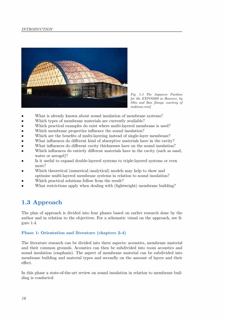
Fig. 1.3 The Japanese Pavilion for the EXPO2000 in Hanover, by Otto and Ban [Image courtesy of makmax.com]

17
TIME SCHEDULE
Phase 2: Variant study and measurements (chapters 5 and 6)
During this phase a basis is given for all further variants, where the conclusions from earlier research are adopted on the research done in phase 1 and some restrictions. Some membrane configurations with different kind of filling materials will be measured in a laboratory and the results will be analyzed.
Phase 3: Theoretical validation and optimisation (chapters 7 and 8)
The measurement results will be discussed using a number of numerical and analytical models. What is the conclusion from the measurements? What can be optimised based on these theoretical models, in order to gain an even better performing membrane structure in relation to sound insulation? All this, is done during this phase. The end result of this phase will be a (or multiple) best performing solution for practical use.
Phase 4: Practical solutions (chapter 8)
During this phase possible solutions are presented and detailed.
1.4 Time scheduleTo make an estimate of the time needed for this research, in table 1.1 a period is reserved for each phase described above.
Phase Main subject Time span Date Year
1 Orientation and literature 2.5 month Half Nov. to end January 10-112 Research for present knowledge 1 month February 20113 Improved system and 1.5 month March to half May 2011 measurements4 Theoretical validation 1 month Half May to half June 20115 Optimisation and practical 1 month Half June to half July 2011 solutions
Table 1.1 Time schedule Master thesis

18
Orientation
Acoustics Material
Conclusion
Theoretical validation
Conclusions andrecommendations
Fig. 1.4. Visual schedule of the approach plan for this Master thesis
Common groundsState-of-the-art review
General
Layers
Room acoustics
Soundinsulation
Phase 1
Phase 2
Phase 3Phase 4
INTRODUCTION
Improved system(triple-layer)
Measurements
Computer model
Mathematical model
Optimisation
Practical solutions


21
Acoustic theory 2Before investigating the absorption and transmission characteristics of membrane struc-tures, an investigation into the acoustic theory and what is known in relation to membra-ne structures has been carried out. These are presented in this chapter and the next res-pectively. In section 2.1 room acoustics is shortly discussed followed by sound insulation aspects in section 2.2. Multi-layered walls are discussed more in detail and a beginning is made for triple-leaf systems. For basic acoustic theory, please refer to Appendix 2A.
2.1 Room acousticsRoom acoustics includes all aspects of the behaviour of sound in a room, from the physi-cal aspects to the subjective effects. So room acoustics deals with the measurement and prediction of the sound field resulting from a given distribution of sources as well as how a listener experiences this sound field. When trying to achieve a ‘good’ acoustic envi-ronment, from introducing absorbers to designing concert halls, attention must be paid to the physical and psychological aspects. For now, the emphasis will be on the physical aspects of room acoustics and not on the psychological aspect. Relevant room acoustical parameters shall also be discussed.
2.1.1 Sound reflection
Sound reflection is best described for different kind of directions of incidence. Please refer to Appendix 2B for details on this matter.
2.1.2 Diffuse sound field
In building acoustics, room acoustics included, a statistical description of pure tone responses for a room isn’t that interested. Responses will be averaged over frequency bands, octave or one-third-octave bands and what often is done is looking at the energy or energy density. And thus a model which is used is called the ‘classical diffuse field model’. An ideal diffuse field should imply that the energy density is equal for every inch in the room, but an actual definition is never made. Entire studies are performed on the definition of diffusivity, some suggestions are:
• In a diffuse field the probability of energy transport is the same in all directions and the energy angle of incidence on the room boundaries is random.• A diffuse sound field contains a superposition of an infinite number of plane, progressive waves making all directions of propagation equally probable and their phase relationship are random at all room positions.

22
2.1.3 Reverberation and steady-state energy density
For formulas on reverberation time and steady-state energy density, please refer to Ap-pendix 2C.
2.1.4 Sound absorption and absorbers
Apart from the attenuation of sound in air, other loss mechanisms which reduce the energy of sound waves in a room are of importance. The magnitude of wall absorption to which sound waves are subjected and its frequency dependence varies considerably from one material to another. Since the boundary absorption is of decisive influence on the sound field in a room, the understanding of various absorption mechanisms and the knowledge of various types of sound absorbers is important. Sound absorbers are usually employed for one of the following reasons:
• To adapt the reverberation time• To suppress undesired sound reflections (e.g. echo’s)• To reduce the acoustical energy density, i.e. the sound pressure level.
There are two main groups of acoustics absorbers: resonance absorbers (e.g. membrane absorbers or absorbers based on the Helmholz principle) and porous absorbers (e.g. mi-neral wool, plastic foams, fabrics, etc.) (Figure 2.1).
The definition of ‘membrane absorbers’ in this case is not the same as for this thesis. Here the word membrane is usually used for very thin metal or aluminium sheets, but some-times also refers to plastic materials. Since membranes, in association with this thesis, are for example (PVC-coated) polyester or (PTFE-coated) glass-fibre fabrics (the polyester or glass-fibre threads are woven into fabrics), they fall into the category of porous ab-sorbers as construction material itself. But since membranes used for construction (this thesis) are under tension, resonance absorbers are also discussed.
Fig 2.1 Left: basic type of sound absorbers (c and d only work properly when absorption material is present in the cavity). Right: basic type of resonators [1]
ACOUSTIC THEORY

23
SOUND ABSORPTION AND ABSORBERS
Resonance absorbersAn idealized resonator is considered here, which consists of a membrane (or a thin wood-en panel) with mass m per unit area mounted in front of a rigid wall and parallel to it. Under impinging sound waves the membrane panel will start to vibrate, controlled by its mass and air cushion behind. Vibration losses are then in relation to its specific airflow resistance Rs (section 2.3.1: porous materials). This type of absorbers has a frequency-selective absorption characteristic which makes it ideal to use for control of reverberation (the frequency range can also be increased by adding absorption material in the cavity. This is however bought in the expense of the peak frequency). Here for ‘membrane’ a pa-nel of wood, chipboard or gypsum is used. When the mass layer is perforated or slotted, it is referred to as a Helmholz resonator.
The ‘resonance’ occurs at the angular frequency (eq. 2.1), as shown from the expression (eq. 2.2) of the impedance of the air cushion:
Z R i m cts= + −
ω
ρω0
2
(2.1)
(2.2)
, where is the resonance frequency of the system, s ( ) is the spring (air) stiffness and m the mass of the plate (the stiffness of another material is , where is the dynamic elasticity modulus of that cavity material).
Helmholz resonatorsHelmholz resonator absorbers are based on the principle that the air in the holes of the plate represents a mass and the air volume of the ca-vity behind the plate represents the spring stiff-ness, i.e. a simple mass-spring system (figure 2.2). To absorb or dissipate acoustic energy a resistive component should be added, traditionally filling the cavity partly or wholly with a porous absor-ber. One can think of perforated plates (steel, alu-minium, plastor or wood), foils, microperforated panels or membrane fabric.
The (frequency dependent) absorption area is de-rived in [2], and is expressed by
Fig 2.2 Helmholz resonator: a) realization; b) schematic [2]
A AQA
ωω ω ω ω
( ) =+ −( )
max
1 20 0
2 (2.3)
f0 0 2=ω π = ρct0
2
Et
dyn
Edyn
ωρ
00
21
2
=
=
cmt
sm

24
ACOUSTIC THEORY
, with is the quality factor, the radiation resistance and the angular resonance frequency given by the general formula . Here is the elastic stiffness of the air cushion. M represents the mass in kg of the porous material.
Absorption by porous materialsAs said before, well-known porous materials are products of mineral fibres and plastic foams (with an open cell structure). Commonly used are blankets of mineral wool, either glass or stone wool. These can be found in the type of “elastic” blankets, but also com-pressed into stiff boards (suspended ceilings). The fibre diameter is in the range of 2-20 , commonly 4-10 and is distributed anisotropically (orthotropic). Today plastic fibre products become popular as well, like polyester fibre wool is also used for construction. These diameters are usually larger and in the order of 20-50 and again, these fibres are lined up anisotropically (refer to section 5.2.3).
Practically all used sound absorbers contain some porous material in them. The dissipa-tion process of sound waves arriving at the surface is discussed now. When sound waves impinge on a smooth surface inevitable reflection losses (inevitable wall absorption) take place, caused by viscous and thermal processes and occur within a boundary layer next to the surface of about 0.01 to 0.2 mm. These absorption effects are negligibly small in this case, but at rough surfaces the volume of the zone in which the losses occur increases. It is even more noticeable when the material actually contains pores, channels and voids connected with the outside air (figure 2.3).
Pressure fluctuations give rise to alternating air flows in the pores and an amount of me-chanical energy is converted into heat. This mechanism of sound absorption is valid for all porous materials.
The main characteristic parameters of a porous material (porosity and specific flow re-sistance) are discussed in section 2.2.1 (porous materials). In order to understand the basic process, the idealized, so-called Rayleigh model is used, in which the skeleton of the material consists of a great number of similar, equally spaced and parallel channels and where the material itself is completely rigid (figure 2.4). Using this model the characteris-
Q MRAr
= ω02 Rr ω0
ω02 = s M s c S
V= ρ02 2
µmµm
µm
Fig. 2.3 Lossy boundary layer: a) in front of a smooth wall; b) in front of a rough wall; c) in front of a porous material [2]

25
tic impedance in a single channel is derived in [2], obtaining the ratio of sound pressure to velocity (averaged flow velocity over the cross-section of the channel):
SOUND INSULATION
From this, the average characteristic impedance and the airflow resistivity can be expressed, ac-cording to the following equations.
Z pv
c iR0 0
0
1 2
1' = = −
ρ
ρ ω(2.4)
Fig. 2.4 The Rayleigh model [2]
Z Zn0
0='
r Rn
=
(2.5)
(2.6)
For highly porous materials such as rock wool or mineral wool the porosity is closely to unity and the airflow resistivity in the range of 5000 to 105 Pa s/m2. When applying this to a porous layer of thickness t in front of a rigid wall we obtain for the wall impedance and for the absorption coefficient (asymptotically for high frequen-cies):
Z cn
i n r1
0
0
1 2
1= −⋅ ⋅
ρρ ω
α∞ = +4
1 2
nn( )
(2.7)
(2.8)
For the impedance of the other frequencies, eq. 2.7 can be used. For all frequencies at normal incidence eq. 2B.4 (App. 2B) and the specific acoustic impedance can be combined to find the absorption coefficients. Z represents the wall impedance here, with the velocity normal to the wall: . For oblique incidence at all fre-quencies eq. 2B.7 (App. 2B) can be used.
2.2 Sound insulationThis section deals with the sound transmission between two adjacent rooms or from the outside into the building and vice versa. The main practical aspects here are noise control with indoor rooms with respect to traffic noise or residential noise. But also noise from inside a building (e.g. concert hall or music theatre) to the outside is relevant [3]
There can be two reasons for noise entering a room from the exterior, namely that walls are directly excited by forces acting on those walls or ceilings by walking or by machinery.
Z Zca s, = ρ0
vn Z pvn surface
=

26
This structure-borne sound results into vibrations which can be transmitted to other floors and thus rooms. Since structure-borne sound insulation is of minor importance when dealing with membrane structures, this is not discussed here (impact noise from e.g. rain is not discussed either).
Another reason for noise can be speech, electronic devices and music for instance which give their vibrations through the air (hence: airborne sound) via the walls and floors (momentarily structure-borne sound) into the other room. This type of sound insulation is discussed in the present research.
Furthermore a distinction can be made by the path the sound travels to enter another room. The above two mentioned reasons can be both direct and flanking sound transmis-sion. Flanking sound transmission is spoken of when sound travels first through a separa-te, adjecent building element after entering the room of interest. Think of common floors or ceilings both in the source or receiving room. This type of sound transmission will not be dealt with yet, and the focus will be on direct sound transmission. Yet another path can be distinguished which will not be dealt with here is indirect airborne transmission, which can be pictured as sound travelling through common hallways or ventilation ducts.
For some basic sound insulation quantities, please refer to Appendix 2D.
2.2.1 Direct airborne sound transmission
As mentioned before the (direct) airborne sound transmission will be discussed now. The emphasis is on single or multi-layered (cavity) constructions composed of different kind of materials. Windows, doors and installation (HVAC) noise will not be discussed.
The process of transition from sound energy (longitudinal waves) into vibration energy (transversal bending waves) and back to sound energy again, what happens during sound transmission through a building element, is for the easiest homogeneous plate already very complex. Therefore no closing analytical derivations for sound insulation are pre-sent, so the equations discussed here are a combination of well explainable physical phe-nomenon’s and some empirical approximations.
Solid homogeneous isotropic platesSince in practice membrane structures will be at least two-layered systems; i.e. systems with two membranes with a (empty or filled) cavity for the thermal insulation of the building, this subject will be discussed only briefly. The latter is because some terms and definitions can be explained more easily for single layered systems than for multi-layered systems.
Mass lawWhen a plane wave hits a frictionless plate element, with mass m’ [kg/m2], a reflected, plane wave and a transmitted, plane wave will appear. As said before, a pressure dif-ference will occur which causes the plate to oscillate. This again causes a plane wave at the backside of the plate with a velocity the same as that of the vibrating plate. Through pressure equilibrium the mass law for normal incidence can be derived (for the full deri-
ACOUSTIC THEORY

27
DIRECT AIRBORNE SOUND TRANSMISSION
vation [4]) and is expressed as (the 1 cannot be neglected for membranes!):
R mc
= +
10 12 0 0
2
lg 'ωρ
(2.9)
, where and R is the airborne sound insulation in dB. Important to note are the simplifications made for this mass law. Firstly infinite wall width and length are presumed; secondly, the wall only consists of one layer where the influence of the bending stiffness can be ignored (useful for membranes) and thirdly normal incidence is presu-med which makes this a one-dimensional problem. Mass law shows that for doubling the frequency as well as doubling the mass gives a 6 dB higher sound insulation value. For oblique incidence with angle of incidence eq. 2.9 becomes:
ω π= 2 f [rad/s]
θ
R mc
= +
10 12 0 0
2
lg 'cosω θρ
(2.10)
For diffuse sound incidence (in practice or laboratory) the sound reduction for normal incidence is reduced with 5 dB for ‘normal’ masses, but cannot be done for membranes. Approximating a diffuse sound field can be done by using equation 2.10 with an angle of incidence of 56 and 60 degrees for single-leaf and multi-leaf constructions respectively. Or more correctly by removing ‘cos ’ and replacing the denominator by .
For more elaborate calculation formulas for a single layer (homogeneous) wall a number of formulas are cited in the literature [5, 6]. One approach is described in the NEN-EN 12354-1 code where equation 2.11 [7] describes the transmission factor.
τπ
σση
τπ
=
+
+( )+
<
=
Zfm
a ba b
ff
f f
Z
fc
totc
0
2 2
2 2
2
0
2
ffmf f
tot
=
2 2
2πση
cc
c
tot
Zfm
ff
τπ
π ση
=
0
2 2
2 f fc>
(2.11)
, where a and b are the dimensions of the wall, is the total loss factor, and are the radiation factor for resonant and non-resonant transmission respectively. is described by Sewell [8], according to equation 2.12.
ηtot σ σ f
σ f
σπf k S Fk S
ba
= + − +
= >
12
0 16 14
12ln( ) . ( ) , ( )Λ Λ Λ where (2.12)
, and where k is the wave number and is denoted a shape function. Data for this shape function may be taken from a table (derived by Sewell [8]), giving a value of 0.005 for b/a = 1.5/1.25 m.
F F( ) ( / )Λ Λ= 1
θ 2 30 0ρ c

28
ω πρn mBt
nl
mt, =
+
22 2
is described by Leppington et al. [5] according to equation 2.13 where now (a<b), S and U are the plate area and circumference, parameter is the square root of the ratio (for more on radiation, please refer to Appendix 2A).
Another example, used in this research, is the model by Nederlof and Cauberg [9]. It predicts the entire frequency-dependent airborne sound insulation of homogeneous con-structions, thus including coincidence (equation 2.14).
σπ χ
χχ
χχ
σπ
=⋅ −
⋅+−
+−
<
=
Ucf f S
f f
fc
a
c
c0
2 2 2
0
2 111
21
2
ln for
00 5 0 15
1
1
. .−
≈
=−
ab
f fc for
σfffc
foor f fc>
(2.13)
σχ
f fc
R i mc
ic
= + − +( )
10 1
21 1
0 0
2
2
2
log cos
;
ω θρ
ηωω θ
(2.14)
, where i is the imaginary unit (i2 = -1).
Influence bending stiffnessUnder the influence of a plane wave incident on a wall or floor, this wall or floor will bend due to its attachment to other building parts. Transversal bending waves occur. The am-plitude of these waves depends at first on the bending stiffness only: material, thickness, dimensions and boundary conditions. At certain frequencies bending resonances (plate resonances) could occur, which influence the sound insulation and its mass law.
A second phenomenon which has to do with the bending stiffness, and influences the sound insulation, is when sound waves hit the element at an oblique angle. Under certain conditions the element/plate may vibrate more than expected. This phenomenon is called ‘resonance’ [10] and strongly depends on the critical frequency. For infinite plates (Ap-pendix 2A) no coincidence can occur below the critical frequency, since no radiation takes place from the bending waves.
Plate resonancePlate resonances are standing, bending waves in a simple plate, which can occur in the length or width or two-dimensional. The frequencies which go with these resonances are called ‘eigenfrequencies’. These again depend on boundary conditions: fixed, hinged or free edges. In practice a good approximation is when the edge support is hinged, which gives for the resonance frequencies [11]:
(2.15)
ACOUSTIC THEORY

29
ω = 2π fB Et=
3
12
f t E nl
mw
tc nl
mn m L, . .=
+
=
+0 45 0 45
2 2 2
ρ ww
2
cL
f c mEt
c mB
cc c tcL L
= = = ≈02
30
20
2
212
2 1 864000
π π ρ.
sin2θ
c c B< <0 and λ λf fc= c c B= =0 and λ λθ 90o
c cB= =0
sin sinθλ
λθ
and θ < 90o
η
η =2 2. Tfs
, where l is the length of the plate, b is the width of the plate, B the bending stiffness of the plate, the radial frequency ( ) and n and m are the nodal lines along the length and width respectively. When combining this with the bending stiffness , eq. 2.15 becomes:
(2.16)
, where is the velocity of the longitudinal waves in the material.
Coincidence and critical frequencyCoincidence takes place when the free bending wave in the plate material (originated by a hammer impact for instance) has the same wave velocity as the oblique incident forced, acoustic bending wave originated from the plate. The peaks and troughs occur at the same time; i.e. both waves propagate at the same time and place. So for every wall a frequency, the critical frequency, exists below which no coincidence takes place (please also refer to Appendix 2A):
(2.17)
For oblique incidence, above equation should be divided by .
Three ranges can be distinguished: when the frequency is below the critical frequency, around the critical frequency or above the critical frequency. Below the critical frequen-cy no coincidence is possible (always true for single-leaf membranes since their surface density is very low). At the critical frequency ( ) the lowest frequency for coincidence is at an angle of incidence of . Above the critical frequency coincidence occurs when and for every fre-quency another angle of incidence occurs for coincidence.
The airborne sound insulation is influenced by coincidence to a certain extent however [12]. It is highly dependent on the ability of the wall to convert the energy of the bending wave into heat; i.e. its ability to dampen the bending waves. This ability is put in the loss factor , and is dependent on the measured structural reverberation time:
(2.18)
All dampening mechanisms are included in this loss factor: friction, edge and impedance losses. The loss factor is material dependent and is for most materials around the 1-2 %. Using this loss factor the airborne sound insulation can be calculated [12].
Orthotropic platesOrthotropic plates have different elastic properties in two axial directions. Examples of these types of plates are wooden materials (material anisotropy), fibre-reinforced mate-
DIRECT AIRBORNE SOUND TRANSMISSION

30
k k k kx z= =sin cos sin sinθ φ θ φ and
Z ik k
ksb x b z
= − +
ωρφ φ
θ12
2
2
2
2
4 4cos sin sin, ,
θ
(2.19)
φ
τπ
θ φ
θρ
π
∞ =
+∫∫,
(sin )
cosd
d d
Zc
2
12
2
0 0
20
1
0
2
(2.20)
fc eff,
R R ff
wNR
c effo∞ = + −
+ −
,,
lg lg( )0
10 1 10 2 dB (2.21)
R Pq
R R S r Rtv
SS= = ⋅ =
∆ , and (2.22)
rials and corrugated plates. Orthotropic plates have two critical frequencies, one in each of the two directions. Many materials are orthotropic to some degree, which makes it important to identify when a plate/material can simply be modelled as isotropic or when their orthotropic nature should be taken into account. As a rule of thumb, if the critical frequencies are only a few one-third-octave bands apart it can be treated as isotropic but not if the two critical frequencies are separated by an octave or more. Since membranes can be considered as orthotropic, the theoretical approach is shortly discussed here.
In Appendix 2A (‘Vibration’) the bending wave equation for an orthotropic plate is given. Substituting the plate displacement into this wave equation gives the surface impedance for an orthotropic plate (when ):
Now the angle-dependent transmission coefficient for an infinite orthotropic plate with mass and stiffness can be found. Integrating this over and gives the diffuse incident transmission [13]:
For calculating the (airborne) sound insulation the following formula can be used, where is the effective critical frequency [10]. Effective, since for orthotropic plates the critical frequency is different for each direction.
Porous materialsHigh sound insulation is based on high reflection from a dividing partition, not in dissi-pating the energy in the partition itself (please refer to chapter 6 and 8 for more detailed explanation]. Applying a porous material (e.g. mineral wool, plastic foam products, po-rous fabric or curtains) for good sound insulation is therefore not appropriate. However, it is of interest to look at this, for in practice porous absorbers are sometimes mounted on a will which adds insulation. Moreover, an investigation has been done into permeable (multilayered) membranes for sound insulation (more on this in chapter 4), which makes discussing porous materials relevant to this thesis.
The airflow resistivity is one of the most important parameters to characterize porous materials. The quantities R (airflow resistance, Pa s/m3), Rs (specific airflow resistance, Pa s/m) and r (airflow resistivity, Pa s/m2) are defined as (ISO 9053):
ACOUSTIC THEORY

31
qv
µ
Br
=µ [m2 ]
λpm
λpm
R
rdc
fc
rdc
rdc
o
s
o = +
+
10 1
2 4
4
0 0 0 0
2
0 0
0 0
lgρ
π ρρ ρ
ρ +
2
0 0
22π ρρfc
s
λpm
λpm
λpm
R L Lo p E02= +∆ ∆
∆ ∆L Lp E and
∆L k dp pm=2010ln
Im{ }
, where is the volume velocity (m3/s) of the airflow through the specimen having an area S and thickness t. In the old CGS system (before the SI system) Rs had its own unit, the Rayl. Sometimes an inverse quantity is used in order to characterize the ‘openness’ of a porous material for airflows. This is called the permeability B and is defined by ( is the coefficient of viscosity):
(2.23)
Another important parameter is the porosity n of the material, which is the fraction of volume which is not occupied by the solid structure (please also refer to section 8.2.1).
The model that is described now gives the normal incidence sound insulation for single sheets of homogeneous porous materials [14, 15]. In this model three frequency ranges are used, A, B and C. Each range is defined in terms of material thickness d, relative to the wavelength of sound within the equivalent gas, .
Frequency range A: d < /10The skeletal frame of the porous material has a low mass impedance; therefore the com-pressions and rarefactions of the air particles in the pores of the material cause the entire frame to move.
According to Schultz [16]:
(2.24)
Frequency range B: /10 <= d < There is no specific model for this range. A smooth transition curve shoot be fitted between ranges A and C.
Frequency range C: d > /10Now the skeletal frame can be considered as rigid. A fraction of the incident sound waves will enter the porous material. Inside the sound attenuates while propagating in the air pores. At the exit surface a fraction is reflected and the remaining s transmitted. The normal incidence sound insulation depends on the propagation loss and the entry/exit loss [15]:
, where are:
(2.26)
(2.25)
DIRECT AIRBORNE SOUND TRANSMISSION

32
ρ 20
20c d Ecav m m1 2+
θ
Rm mmm
m mcav
ms, log cosθ
ωω
θω
= −+( )
+
+( )⊥
10 12 21 2
2
1 2
2
22
2
1 2
ρρθ
ωω
θ0 0
2 2
22
2
1c ms
cos cos
−
⊥
ω πms mscav
f m m Em m d⊥ ⊥= =+2 1 2
1 2
( )
E = ⋅1 4 105.
fT
Cavity constructionsSince membrane structures in practice are at least double layered, this section is very important to describe the sound insulation. The formulae below are derived for plate sys-tems with an infinite bending stiffness (and infinite dimensions); therefore these are not just applicable for membrane structures. Please refer to chapter 4 for a more extensive discussion.
Cavity constructions consist of two (or more) layers (leaves) of material with an empty or filled cavity in between. These leaves may be or may not be mechanically coupled. If the stiffness of the system is determined by the cavity itself, the air, these are referred to as cavity constructions. When the stiffness is coming from a filler material in between it is referred to as multi-layered constructions [16].
Mass lawFor the mass law for cavity constructions the derivation is along the same lines as for sin-gle wall constructions. The mass law is an approach, so coincidence will not be taken into account. Furthermore with all formulae below the assumption is made that both leaves are infinitely stiff (which is obvious not the case for membrane structures) and that is negligible relative to .When the leafs are presented as masses and the air cavity as spring, via Hooke’s law and Newton’s second law of motion, the airborne sound insulation for cavity constructions (with oblique sound incidence with an angle of incidence ) can be written as [16]:
, where is the angular frequency where mass-spring reso-nance for normal incidence sound waves occurs and E is the Young’s modulus of the spring (for air Pa at standard atmospheric pressure).
From eq. 2.28, the theoretical mass law for cavity constructions, the general behaviour of the airborne sound insulation can be explained (figure 2.5). From onwards, eq. 2.28 isn’t predictive, because it assumes no resonances and thus keeps increasing with 18 dB/octave.
∆L
Zc
Zc
E
pm pm
= − −
+
10 1
0
0 0
2
0
0 0lg
Re Im, ,
ρ ρ −
+
+
2 2
0
0 0
2
0
0 0
1 4
1
Im
Re
,
,
Zc
Zc
pm
pm
ρ
ρ
+
2
0
0 0
2
Im ,Zcpm
ρ
(2.27)
(2.28)
ACOUSTIC THEORY

33
R mm
mmcav ms, log= +
10
2 21
2
2
1
2
Fig. 2.5 General frequency-dependent behaviour of cavity constructions [16]
f sm m
f cd m m
ms t
mscav
= +
= +
12
1 1
21 1
1 2
0 0
1 2
π θ
π θρ
cos
cos
'
→ ≈+
⊥f
m mm m dms
cav
60 1 2
1 2
Rm m
ccav, logcos
θ
ω θρ
= ++( )
10 12
1 2
0 0
2
Mass-spring resonanceIn figure 2.5, mass-spring resonance is clearly showed. This resonance gives a minimum for the airborne sound insulation expressed as:
(2.29)
This resonance occurs at a certain resonance frequency, shown in the first expression of eq. 2.28. The second expression is the same mass-spring resonance frequency, but then for a cavity filled with air.
(2.30)
Below mass-spring resonanceBelow the mass-spring resonance (figure 2.7) eq. 2.60 can be simplified to:
(2.31)
Above equation holds for all angles of incidence, but in practice an (approximated) dif-fuse sound field dominates. For the airborne sound insulation for this random incidence (sound waves impinging the surface at all possible angles) eq. 2.31 should be reduced with 5 dB (not valid for membranes) [16]. For random incidence an angle of incidence of 60o may be used.
DIRECT AIRBORNE SOUND TRANSMISSION

34
f cd
f cdT
cavT random
cav
= → =0 0
2 4 5π θcos .,
R R m R mcav gle gle, sin , sin ,( ) ( )θ θ θ= + +1 2 6 [dB]R mgle xsin , ( )θ
fn fm
fn fm
f ncdsw ncav
,0
2
R m m dccavcav
, log cosθ
ω θρ
=
10
2
31 2
3
20
30
2
or written in a different form as:
Rcav,θθ θ θω θ
= + +
R m R m d
cgle glecav
sin , sin ,( ) ( ) log cos1 2
0
10 2
Above mass-spring resonanceSimilarly, the mass law above mass-spring resonance can be expressed by:
Similarly this equation can be reduced with 8.5 dB (not valid for membranes) for random sound incidence. Just like below mass-spring resonance, for random incidence an angle of incidence of 60o may also be used.
According to above equation the sound insulation will keep increasing with increasing frequency. Practice shows that the cavity-term in the second expression of eq. 2.32 has a maximum for 6 dB, which will be reached at a certain transition frequency (figure 2.5):
(2.32)
(2.33)
From this frequency and higher, the sound insulation no longer increases but stays at a steady . This equation can be extended for more leaves; i.e. adding one leaf adds to the equation and every cavity 6 dB (not valid for membranes).
Cavity resonancesAt lower frequencies the above formulae for the so-called non-resonant transmission are valid, but for higher frequencies another approach should be used, the so-called ‘Statis-tical Energy Analysis’ [3]. At these higher frequencies resonant transmission dominates. This statistical approach is based on a sound field with a set of resonance frequencies, which are called (resonance) modes. Sound transmission from one system (air space or room) to another (cavity construction) is described as acoustic power transmitted from one mode (with frequency ) to another mode (with frequency ). If there is no acoustic damping (absorption material) in the cavity vibrations occur when and are closely together. The two masses (leaves) are then acoustically coupled. These cavity resonances, or standing waves, occur at a certain frequency:
(2.34)
, where n (n= 1,2,3,4, etc.) represents a random number of frequency mode (figure 2.6).
For every resonance a sharp drop in the airborne sound insulation takes place, as seen in figure 2.5.
ACOUSTIC THEORY

35
dn
c fcavsv n= =λ
λ, /2 0 with
Fig. 2.6 Standing waves in a cavity (modes n = 1-4) [16]
f X X s sm m m m mm
X s
msmsm = ± − + +
=
1
24 1 1 1
32
21 2
1 2 2 3 1 3
1
π' '
, where'' ' ' '+
+ +s
msm
sm
2
2
1
1
2
3
sx'
s cdgascav
' = ρ0 02
(2.35)
Sound absorption in the cavityWhen resonance occurs (for instance in a cavity) the air particles make great movements (with high amplitudes) around their equilibrium position. Limiting this amplitude can increase the sound insulation, which can be done by using absorbing material so that considerable friction occurs in the narrow openings of the material.
Structural coupling between leafsCouplings between the different leaves in a cavity construction may reduce the sound insulation considerably. Factors that influence this are: the type of coupling (point or line), the rigidity of the coupling (rigid or flexible) and the amount of couplings per unit of length or area. Couplings are not taken into account for membrane structures, since not much coupling is used.
Triple-leaf constructionsFor an easy approach to multiple leaf constructions, earlier is shown that eq. 2.29 could be complemented with masses and cavities (6 dB). For a so-called plate-cavity-plate-cavity-plate system modelled with lump masses and springs, there are two resonance frequencies to consider [17]:
, and where is the dynamic stiffness of the spring (the cavity) per unit area
( ).
In 1990 Vinokur [18] used the impedance method [19] to find the transmission coefficient
DIRECT AIRBORNE SOUND TRANSMISSION

36
for triple-layered plate systems of infinite extend. His research was focussed on triple-glazing. The transmission was derived for a plane harmonic wave of frequency f and at an angle of incidence :θ
τ ψ ψ ψ ψθ = + + + + + + + +1 1 2 3 1 2 1 2 3 2 1 3 1 2 1 2 3 1Z Z Z Z Z d Z Z d Z Z d d Z Z Z d( ) ( ) ( ) ( )ψψ ( )d22−
Z iZ Z Z Zj j j j j j= − − +1 22
1 221( ) η
ZM f
cjj
10 0
=π θ
ρcos
Z ffjcj
2
2
=sin θ
ψ θ η( ) exp( cos ); ,d ikd M fj j j j cj= −1 2 and
(2.36)
Here Z is a dimensionless bending impedance of the jth plate: ,
where and .
Also are the mass per unit area, the internal
loss factor and the coincidence frequency of the jth plate respectively. The sound insula-tion can then be calculated using .
2.2.2 Multiple Layer Model
The MLM (MeerLagenModel) [20] is described by Nijs in [21, 22]. In this program the Wave field Extrapolation model (“WE-model”) is used to dissolve the sound waves coming from a point source into a series of plane waves. The three-dimensional Helmholz equati-on, using the WE-model, is dissolved in plane waves using the Fourier transformation [23, 24], (analogous to the theoretical models described in section 3.1). So, the wave number perpendicular to the wave front is dissolved in three dimensions and the sound pressure is transformed; to the symbol P. Hereby creating a simple, one-dimensional equation, des-cribing three-dimensional waves. The Fourier transformed Helmholz equation (eq. 2.37) uses two new parameters to create a Matrix form. The first (eq. 2.38) can be considered to be the Fourier transformed particle velocity and the second (eq. 2.39) as the, for nor-mal sound incidence, characteristic impedance of the medium.
−∂∂
−∂∂
+ =j
z jPz
k Pzωρωρ1 02
Vj
Pzz = −∂∂
1ωρ
Wkzz
= −ωρ
(2.39)
(2.38)
(2.37)
The solution of the Matrix equation can be easily found when the medium is homoge-neous. The transformation Matrix then makes a connection between the quantities in equations 2.38 and 2.39. For layered media P and Vz are calculated for every layer and then via impedances extrapolated to the next layer (figure 2.7), which is basically the same principle as Sakagami uses in chapter 3.
ACOUSTIC THEORY
R = −10log( )τθ

37
τ = + + +( )2 11 12 0 21 0 22
2/ / , ,t t W t W tz z
R t t W t W tz z= + + + −20 611 12 0 21 0 22log( / ), ,
Figure 2.7 (Left) Extrapolation scheme for three layers. (Right) A multiple layer system with n layers, des-cribing all parameters. W is the characteristic impedance. [21]
The transmission coefficient used in the above described model can be written according to equation 2.40. [25]
, where Wz,0 is the impedance of the medium on the sound incidence side and the back-side. From this the airborne sound insulation can be calculated using equation 2.41.
(2.41)
(2.40)
MULTIPLE LAYER MODEL
Two disadvantages in the model are that an infinite large construction can only be tested due to the mathematical techniques used (especially disadvantageous for low frequency plate resonances) and that edge restraints cannot be modelled.
The program can calculate the sound insulation for a diffuse sound field or for a certain angle (used here is the diffuse sound field only). Default for the weighing function of the loss factor is -1 and the weighing for sin*cos^(1+weighing) is 0.5. The program further-more calculates with a linear progress of the frequencies with a certain begin value, step size and end value even if the output is in octaves.
The input for the construction consists of a couple of parameters, different for solids or li-quids (like air). For masses (“sol(id)”) the thickness, mass (kg/m3), Young’s modulus, two dissipation factors and the Poisson ratio should be entered. For springs (“liq(uids)”) the thickness, mass (kg/m3), gamma (The Young’s modulus of the air layer), two dissipation factors and the flow resistance should be entered (refer to Appendix 7A for the input file).

38
References
1. Vigran, T.E. (2008), Building acoustics. First edition, published by Taylor & Francis2. Kuttruff, H. (2009), Room acoustics. Fifth edition, published by by Spon Press3. Hopkins, K. (2007), Sound insulation. First edition, published by Elsevier Science Publishers Ltd.4. Martin, H.J. (2007). Geluidisolatie. Collegedictaat TU Eindhoven behorend bij het college ‘Akoestiek 7S510’5. Leppington, G.G., et al. (1982), The acoustic radiation efficiency of rectangular panels, Proceedings of the Royal Society of London, A382, 245-2716. Nijs, L. & Wapenaar, C.P.A. (1990), The influence of wind and temperature gradients on sound propagation, calculated with the two-way wave equation, J. Acoust. Soc. America, Vol. 87, 1987-19987. Josse, R. & Lamure, J. (1964), Transmission du son par une paroi simple, Acustica 14, 266-2808. Sewell, E.C. (1970), Transmission of reverberant sound through a single-leaf partition surrounded by an infinite rigid baffle, J. Sound Vib., Vol. 12, 21-329. Nederhof, L., Cauberg, J.J.M., Nijs, L. and Tenpierik, M.J. (??), Architectural Acoustics (03 Single-Leaf Walls)10. Cremer, L. (1942), Theorie des Klopfschalles bei Decken miet schwimmendem Estrich, Acustica,2, 167-17811. Fahy, F. (1994), Sound and structural vibration – radiation, transmission and response, First edition in 1985 by Academic Press Limited. Fourth printing in 199412. Nederhof, L. Cauberg, J.J.M., Nijs, L. and Tenpierik, M.J. (?). Architectural Acoustics (03 Single-Leaf walls)13. Heckl, M. (1960), Untersuchungen an orthotropen Platten, Acustica, 10, 109-11514. Bies, D.A. and Hansen, C.H. (1979), Notes on porous materials for sound absorption, Bulletin of the Australian Acoustical Society, Vol. 7, 17–2215. Cremer, L. and Müller, H.A. (English translation by T.J. Schultz) (1982), Principles and Applications of Room Acoustics, vol. I, London and New York: Applied Science Publishers16. Nederhof, L. Cauberg, J.J.M., Nijs, L. and Tenpierik, M.J. (?). Architectural Acoustics (04 Cavity constructions).17. Blevins, R.D. (1979), Formulas for natural frequency and mode shape. Van Nostrand Reinhold.18. Vinokur, R.Y. (1990), Transmission loss of triple partitions at low frequencies, Applied Acoustics 29, 15-2419. Vinokur, R.Y. & Lalayev, E.M. (1979), Method of calculation of sound insulation of triple sealed windows, Struggle against noise and sound vibration, MDNTP, Moscow, 37-43 (in Russian)20. Nijs, L. (Windows-version 2000), Het MeerLagenModel – De berekening van de geluidweerstand van een meerlaagse constructie (software program)21. Nijs, L., (2001), Een rekenmodel voor de luchtgeluidisolatie van meerlaagse constructies, Deel 1: theorie plus toepassing op enkelvoudige platen, Bouwfysica, Vol. 12, No.2, 11-16 22. Nijs, L., (2001), De luchtgeluidisolatie van spouwconstructies berekend met een meerlaags rekenmodel, Bouwfysica, Vol. 12, No.3, 9-1523. Nijs, L. & Wapenaar, C.P.A. (1990), The influence of wind and temperature gradients on sound propagation, calculated with the two-way wave equation, J. Acoust. Soc. America, Vol. 87, 1987-199824. Bruijn, A. de (1997), Geluidabsorberende materialen en constructies voor gebruik onder water, Nederlands Akoestisch Genootschap, Journaal 137, 25-40
ACOUSTIC THEORY

39
25. Pierce, A.D. (1989), Acoustics, an introduction to its physical principles and applications, New York
REFERENCES

41
Acoustic properties of membranes State-of-the-art review 3In this chapter the present theoretical knowledge of the acoustics of membranes is dis-cussed. This chapter is arranged in correspondence with the preceding chapter. First the room acoustics’ important aspects will be discussed in section 3.1, but with the emphasis on the aspects of sound insulation in section 3.2. Single-layer membranes are discussed shortly, double-leaf systems more extensive and concluding a triple-leaf system is descri-bed.
Research on the acoustic performance of membranes has been done more extensively since 1990. Before that, Croome (1985) [1] and Martin (1989) [2] wrote on the acoustic design for membrane structures. The start of more research on acoustic properties was done by Hashimoto, Sakagami, Takahashi et al. [3-13]. They did research mainly on absorption and transmission coef-ficients in combination with single and multilayered systems with or without permeable membranes. Mostly the absorption coefficient was analyzed (characterized by the diffe-rence of absorption and transmission coefficient; i.e. the dissipated energy in the structure itself). Most of their research has been done in the period of 1998 to 2005.
In the category of sound insulation Hashimoto et al. [3] wrote an article in 1991 about hanging additional weights on the membrane’s surface to overcome the low mass which comes with membrane fabric. He expanded this theory in his paper from 1996 [4] and was aided by the effort of Maysenhölder [14].In Germany, since 2002, Weber and Mehra [15, 16] did research at the Fraunhofer In-stitut für Bauphysik on membrane material properties and sound insulation, sometimes through the theory of membrane and foil based noise barriers. They were aided by research done by Haberkern et al [17]. Similar research was conducted by Guigou-Carter in France in 2004 [18] and 2008 [19].
In section 3.1 the knowledge on the dissipated energy, thus absorption and transmission coefficients, is presented. Section 3.2 is about sound insulation aspects only, but both sec-tions are overlapping. In section 3.3 the contex-T project is discussed shortly and some example projects are shown in section 3.4.
3.1 Absorption and reflection coefficientsThe first (actually second, Moulder and Merrill [20] were first) more extensive research into acoustic properties of membrane materials was done by Croome in 1985 [1]. Theory shows that absorption coefficients can be calculated with (see chapter 2), meaning that and thus all absorption is in fact transmission. From experiments done by Moulder and Merrill and Croome it shows that at higher frequen-cies there is not such a good agreement with the calculated and experimental values of the absorption coefficients, because the airflow resistance does not increase at the rate postulated by theory due to the nature of the flexible materials. It is useful to say that
α ω ρ= + −[ ( ) ]1 2 2 1m cα τ=

42
Moulder and Merrill also tested Duraskin fabrics (fibre glass) which were coated to be impermeable. Thus the air flow resistance was infinite. Results showed that the sound absorption was very low. Most of the research on permeability of membrane structures in the future is based on this conclusion. Also some first research was done there on double-leaf membrane structures with porous material in the cavity. Kuttruff [21] proposed a so-called “modified mass”, for membrane materials, for the above equation for :α
m b xn
' ( )=
+ρ0 0 2 (3.1)
, where represents the thickness, , r is the radius of perforation, n the porosity = and is the cross-sectional area of each hole and the membrane area per hole. Later on, Cremer and Müller [22] did research on air through pores and showed for the absorption and transmission coefficients:
b0 z r= 0 8.S S2 1/ S1 S2
τ =+
22
2ZZ R
α =++
42 2
Z Z RZ R( )
( )
δ α τ ( )= −
τω
ω=
( ) + ( )+( ) + ( )
1 11 2 1 1
2 2
2 2
R mZ R m/
αω
ω=( ) + ( ) + ( )
+( ) + ( )1 1 1
1 2 1 1
2 2
2 2
ZR R m
Z R m/
(3.3)
(3.2)
, where R represents the flow resistance and Z the wall impedance. In practice, however, wind forces cause movement which in turn reduces the relative motion in the pores. This again, determines the friction losses and thus the dissipation coefficient . Hence;
(3.5)
(3.4)
The first step towards membrane panels as effective absorbers is made by Croome (1985), after his tests on single layer porous materials behind membranes or membranes only. He also commenced some research on the sound insulation of double-leaf membranes, with the use of conventional theory, but no conclusions were presented.
In 1989 Martin [2] did measurements in a prestressed, pneumatic membrane dome with coated polyester fabrics (surface density: 0.5 – 1.0 kg/m2). In his conclusion he said that the low sound absorption present resulted in high reverberation times. For general design purposes he proposed to use diffusing convex shaped membrane structures (instead of concave) to get rid of the flutter-echo’s.
3.1.1 Single-leaf systems
Until 1994, no theoretical models specifically attuned to membrane structures have been studied for applications for this thesis. Sakagami et al. [8] made the first steps to absorp-
ACOUSTIC PROPERTIES OF MEMBRANES

43
tion and transmission through the theoretical study of reflection of an infinite, single-layer membrane. He did this by expanding the work of Morse and Ingard [23] on sound transmission of membranes. Reflection is of lesser importance to this thesis, but what Sa-kagami in this paper discussed as well was the membrane’s tension. And tension is one of the first membrane characteristics thought of when evaluating the acoustic performance. Through the transformed unit response of an elastic plate the reflected pressure can be found [8]. This pressure equation shows that the coincidence effect does not occur in the membrane, but if T (tension) and m (mass) satisfy the relationship , then , so that goes to infinity. The reflection characteristics can be affected by m and T, but the effect of the tension is al-most negligible. This then holds for absorption and transmission as well. This conclusion, drawn by Sakagami in 1994, has been adopted by all further studies and is done in the present research as well.
Together with Moulder and Merrill and Pierce’s ideas, Takahashi et al. [13] wrote in 1996 a paper on the absorption and transmission coefficients of a single permeable membrane. Membranes have a certain degree of acoustic permeability, which has been disregarded in general membrane-vibration theory [8]. Four parameters of the membrane and its structure are most important for the acoustical performance, namely: density, thickness, tension and permeability. Permeability is expected to be the most significant. Takahashi also discussed the absorptive qualities of a layered membrane, but this actually consisted of a single membrane with different air layers between the membrane and a solid wall.
He presented a theoretical model for single-leaf permeable membranes and did a parame-tric study (figure 3.1). Using formulae derived by Sakagami et al [8], a more elaborated theoretical derivation was given using the sound pressure on both sides to find the vibra-tion displacement from the convolution theorem. Solving the equations using the Fourier transform technique the transformed expressions for the pressure and vibration velocity were obtained.
Again, taking the inverse transform of the newly derived equations and substituting this result into a Helmholz-integral formula, one obtains the reflected sound pressure and the transmitted sound pressure pt :
U k( )
m Tc= sin2
02
θ k km0 sinθ = U km ( sin )0 θ
pr
p x z i F kArM
ik x z( , ) cos ( sin )coscos
e (sin cos )=+
+⋅ −θ ρ ω θ θ
θθ θ0
20
20 (3.6)
SINGLE-LEAF SYSTEMS
p x z A i F kAt
M
M
ik x z( , ) ( sin )coscos
e (sin cos )=+
+⋅ −2
20
20 0
ρ ω θ θθ
θ θ (3.7)
, where , Rs is the specific flow resistance = , is the particle velocity, the vibration velocity of the membrane and F (arbitrary function [8, 13]) is too elaborated to discuss here, but can be found in [8]. The absorption coefficient at an angle of incidence theta can be calculated then as and the transmission loss . Transmission loss is a term often found in literature and refers to
A cRMs
= ρ0 0 ∆Pv vf m−
αθ = −1 2prTL ptθ = ( )10 1 2log /
v fvm

44
Fig. 3.1 Analytical model and geometry used by Takahashi [13]
the Sound Reduction Index (or: sound insulation). In his parametric study, tension T, surface density m and the specific flow resistance Rs were changed to show the effect of each parameter. Figure 3.2 shows this clearly.
Tension is negligible, since the tensile strength of membranes is N/m and below this range no effects occur. The surface density has small effects: when m increases, decreases and TL increases. But what is of most influence is the permeability (looked at through the airflow resistance R): when R increases, decreases a lot and TL increases a lot. An important conclusion here is that the airflow resistance is of great importance to the sound insulation of membranes and when it increases the sound insulation increases as well.
1 1 5 105− ⋅.α
α
ACOUSTIC PROPERTIES OF MEMBRANES
Fig. 3.2 Effects of the tension, surface density and flow resistance respectively. For a) the absorption coefficient and b) the transmission loss [13]
Concluding Sakagami et al. wrote in his 1996 [11] paper that “membranes alone cannot absorb the sound very well”. In this paper he did research for membrane-type absorbers with a filled cavity between membrane and a solid wall. And thus, from 1996 on, most

45
papers were on double-leaf membrane systems. A solution for this thesis’ research ques-tion will accordingly be searched in the multi-layered membrane systems.
In 1998 Sakagami et al. [5] did detailed research on the acoustic properties of single layer membranes which where permeable. In [13] (Takahashi’s earlier discussed paper) a so-phisticated approach to permeable membranes was given. In this paper, the same issue will be addressed, but now for normal incidence only. The main focus here is permeability, which Sakagami et al. discussed through an electrical circuit analogy.
The absorption and transmission coefficients from [13] are supplemented with the equa-tions for normal incidence:
αnM M M
M M M
A A MA A M
=+ +
+ + +4 4 4
4 4 4 1
2 2
2 2
τ nM M
M M M
A MA A M
=+
+ + +4 4
4 4 4 1
2 2
2 2
M c mM = ρ ω0 0 / A cRMs
= ρ0 0
(3.9)
(3.8)
, where and . In this paper, (this difference is the dissipated energy in the systems itself) is taken as the characteristic for absorptivity. This is adopted in further studies as well. But the important part in this study is the permeability and the effect of its flow resistance on single leaf membranes. When the flow resistance R increases, the absorption and transmission coefficients decrease to a certain limit [5] (where ).
At low R-values, all energy is transmitted and at high R-values the membrane is almost impermeable, which means an optimal R-value exists for absorption. These values are given for normal and oblique incidence:
α τ−
ωm→∞
R
m c
=
+
1
1 12
2
0 0
2
ω ρ
R
m c
=
+
1
12
2
0 0
2
ωθ
ρcos (3.11)
(3.10)
SINGLE-LEAF SYSTEMS
For high frequencies this optimal value for R will be approximated by . Furthermore, Sakagami et al., presented a useful graph (figure 3.3) where the use of a permeable or impermeable membrane are compared for the TL. Since the tension is not taken into account and R is infinite for impermeable membranes, the curve for imperme-able membranes represents the mass law here.
In 1999 Bosmans et al. [24] did research on the absorption of ceilings with impervious, synthetic material (PVC foil). Since this system contains a solid ‘back’ wall this is of not much interest to this thesis. But he did look shortly at the single membrane layer without
2 0 0ρ θc / cos

46
back wall. Interesting is that he made his derivations through a so-called ‘interfacial ma-trix’. This is based on multi-layered media theory where sound propagation across layers is modelled by transfer matrices. Elastic, porous layers have a 6x6 matrix (compared to 2x2 for fluids and 4x4 for elastic solids). An example of this matrix is shown below (single leaf membrane without back wall and please refer to section 7.2.1 for the background theory on the MLM model):
U k T k m jj j j( ) ( , ,...)= −( ) =−
2 1 22 2 1π ω
10 1
1 00 1
12
1
1
3
3
1
3
ρ ω −−
=
pupu
I JVV
z
z
AMA AMA
=
00
Fig. 3.3 An example of TL for permeable and impermeable membranes [5]
(3.12)
3.1.2 Double-leaf systems
In 1998 Kiyama et al. [25] did a basic study on acoustic properties of double-leaf mem-branes. This will be the basis on which further research has been done (together with the paper of Sakagami et al. discussed above [5]). The geometry of this double-leaf system in infinite extent is shown in figure 3.4.
Analogous to Takahashi’s derivations from his 1996 paper, Kiyama derived the reflec-ted pressure and transmitted pressure, including the wave number representation of the membranes’ unit responses . From these solu-tions the oblique-incident absorption and transmission coefficients are obtained:
ACOUSTIC PROPERTIES OF MEMBRANES
αθ = −1 0 2p xr ( , )
τθ = p x dt ( , ) 2 (3.14)
(3.13)
, and for field-incidence eq. 3.13 and 3.14 are averaged over the angle of incidence (from 0-78o). A couple of membrane figurations where measured in a reverberation room, af-

47
Fig. 3.4 The theoretical model with surface density m, membrane tension T and (wall) admittances A [25]
ter which the results where compared to the theoretical values from the field-incidence averaged (correspond to diffuse field) values of eq. 3.13 and 3.14. As stated before in [11, 13], tension can be ignored and is assumed to be 1.0 N/m throughout the study. First, the comparison is made by the theoretical and measured values of the absorption coefficient, transmission coefficient and their difference. It can be concluded, according to Kiyama et al., that mass-spring resonance occurs (just like ‘normal’) and that the results are in fairly good agreement. In figure 3.5 the results for TL is given and it can be concluded that there is a discrepancy in the high frequency range, but this is according to Kiyama et al. due to measurement errors and gaps.
DOUBLE-LEAF SYSTEMS
Fig. 3.5 Comparison of the theoretical (solid lines) and the experimental (dots)
results of the transmission loss [25]
For all four types the (air) cavity depth was 0.50 m.
No1 has masses of 0.495 and 2.1 kg/m2 for leaf 1 and 2 respectively, No2. 0.995 and 2.1 kg/m2,
No3. 0.495 and 3.3 kg/m2 and No4. 0.995 and 3.3 kg/m2 for the leaves.
Furthermore the theoretical model shows good results up to 1-2 kHz. The only thing is that the theoretical peak frequency appears to be at a higher frequency than that of the measured values.
Kiyama et al. also did a parametric study, which holds the following conclusions:

48
- Surface density m2 has some minimal value, above which not extra mass alters the absorption.- When surface density m1 increases, the absorption decreases (reducing the ability to vibrate). An optimal value for m1 exists.- An optimal value for the cavity depth d exists.- The wall impedances (A1-A4) appear to have the same effects at low frequencies, but they differ at mid and high frequencies. At high frequencies the absorptivity is governed by A1 alone. Another phenomenon is that a mass-spring resonance peak occurs only when admittance is present for the leafs on the inside of the cavity. This implies that absorption in the air cavity plays an important role in causing the mass-spring resonance peak in the absorptivity of double-leaf mem brane systems.A general, more important, conclusion was also given; the surface density of the back mass m2 does not have to be massive to create high absorption.
Supplementing earlier studies [13, 25 and 7 (in Japanese)] Sakagami et al. made in 2000 [7] a model of a double-leaf system with different absorption layers in the cavity. The membrane on incident side is permeable, the second membrane is impermeable, and the tension is negligible (from earlier studies) and taken 1.0 N/m. See figure 3.6.
ACOUSTIC PROPERTIES OF MEMBRANES
Fig. 3.6 Geometrical model for the calculations .It is a double-layer system with an absorptive layer in its cavity [7]
Analoguous to earlier studies he did the theoretical considerations. Conclusions drawn from five different parametric changes, namely 1) the effect of the thickness of the ab-sorptive layer, 2) the air layer behind the absorbent layer, 3) the flow resistance of the absorptive layer, 4) the flow resistance of the permeable leaf and 5) the change of position of the absorptive layer.
1. With increasing thickness, the absorptivity increases (especially at low frequencies). But for high frequencies, with increasing thickness, the absorptivity equals due to more pronounced cavity resonances.2. With increasing thickness, the peaks shift to a lower frequency (also seen in [13]). This is due to, for single layered membrane, the reduction of resistance by the effect of raised vibration at low frequencies.3. Complicated, but in general: the thicker the material, the higher the absorption even if the flow resistivity r is low (with equal flow resistance R).

49
4. This is most significant at high frequencies. There is an optimal R-value maximizing the absorptivity (also [5]). 5. This effect is almost negligible when the cavity depth is less than 15 cm or lower.
In the paper written by Sakagami et al. from 2002, [9] he did the theoretical analysis of his 2000 research above. He especially looked at the permeability of the inner-leaf (on sound incidence side). He found, analogous to previous discussed papers, the sound pres-sures for reflected and transmitted sound. From these the absorption, transmission and their difference can be calculated.
In 2005 Sakagami et al. [12] did research on finite-sized membrane absorbers. Since this is not of importance to this thesis it will not be discussed. This paper is mentioned because since 2005 double-leaf membranes were referred to as DLM’s.
Empirical formulae were derived (with the help of Kuttruff and Ingerlev) for the absorp-tion of fibrous materials by Zhang (2008) [26]. The results from this were compared to the experimental data in figure 3.7. In his paper he also described the vibration sound absorption theory.
DOUBLE-LEAF SYSTEMS
Fig. 3.7 In the figure above the relation is given between the absorption
coefficient and the air permeability.
In the two figures to the right those values are given for
cotton plain fabric and polyester fibre [26]
αρ π
λ=
−( )16
120 0
2
2
f c M vn p
Ds af
a
sin( )
(3.15)
According to the kinetic energy conservation law, Zhang supposed that the sound absorption was de-rived completely from the forced vibration of the material itself. He came up with the following equa-tion for the sound absorption coef-ficient:

50
, where is the surface density , is the maximum air flow speed = , the airflow speed, , is termed the speed atte-nuation coefficient, n porosity and D the cavity depth.
Double-leaf systems with two impermeable layers have been analyzed in [26], double-leaf systems with a permeable leaf on sound incidence side have been studied in [7, 12] and more basic studies were presented in [5, 8, 13 and 25]. In 2009 Sakagami et al. [10] wrote a paper on the acoustic properties of double-leaf membranes with two permeable membranes (for diffuse field incidence. In two earlier Japanese papers Sakagami studied normal incidence). He called this DLPM (figure 3.8).
ACOUSTIC PROPERTIES OF MEMBRANES
M M Ss = / vafv v
eaff
B m tpa= / B lR= 8
2
µ Bmpa
v f
Fig. 3.8 Geometrical model used for the theoretical analysis, the parameters as before [10]
p x zi L k k A J I L k I L k
tm( , )
( sin ) ( sin ) ( sin )=
− − + +ρ ω θ θ θ02
2 0 0 2 2 1 1 0 2 2 0 IIk
3
0
{ }
sinθ
⋅ −( ) exp sin cosi k x k z0 0θ θ
(3.16)
(3.17)
He presented, analogous to earlier papers, the pressures for the reflected and transmitted sound, from where the absorption and transmission coefficients can be calculated through general acoustic theory:
p x zi L k k A J H L k H L k
rm( , )
( sin ) ( sin ) ( sin )= +
− +1 0
21 0 0 1 1 1 1 0 2 2 0ρ ω θ θ θ ++{ }
Hk
3
0 sinθ
⋅ −exp sin coi k x k0 0θ ssθ z( )
, where Hj, Ij, Jj and Lj are complicated functions including various parameters related to the membranes and the air cavity, which are much too extensive to present here. The conclusions can be drawn from figure 3.9 but are quite similar to those found earlier.

51
3.2 Sound insulation aspectsSome sound insulation aspects were already discussed in section 3.1. So is the transmis-sion coefficient for different types of single and multi-layered systems and sometimes the transmission loss TL (term often found in literature; similar to the Sound Reduction Index) presented in those papers. But the main topic of those papers was absorption. A lot more on absorption is done than on sound insulation, because it was always as-sumed that it would be very bad. The only research done on this field in Japan was Hashimoto et al. [3, 4], where he tried to improve sound insulation by hanging additional small weights on the membrane (1991 and 1996). From 2002 until recently especially We-ber and Mehra and Guigou-Carter in Germany and France respectively did research on this matter. This was mostly through research on mobile noise barriers.
But first, in 1985 Croome [1] also had some statements on sound insulation. According to Croome, the usual practical sound reduction formulae (by then), for single layers and for double layers, are accurate enough for design calculations of membrane structures, which he compared the theory with mea-surements done by Moulder and Merrill [20] at 400 Hz. They presented, on this account, some sound reduction index graphs for single and double membranes (fig. 3.10).
DOUBLE-LEAF SYSTEMS
Fig. 3.9 [10]
Left side: the effect of a) the surface density of leaf 1 and b) the surface density of leaf 2. (1) 0.25 (2) 0.5 (3) 1.0 (4) 2.0 and (5) 4.0 kg/m2
Right side: the effect of a) the flow resistance of leaf 1 and b) the flow resistance of leaf 2. (1) 0.001 (2) 100 (3) 816 (4) 1000 and (5) 10000 Pa s/m
R m= +14 5 10. log( ) dBR m m d= + +20 341 2log( ) dB
τ

52
As said before, research in Japan was carried out for the absorption and transmission coefficients and occasionally the transmission loss was calculated. And thus in 2002 Sa-kagami et al. [9] did a study on the acoustical behaviour of double-leaf systems with a permeable leaf on sound incidence side. After theoretical derivations (section 3.1) he con-cluded from good comparison with the experimental data. Fig. 3.11 shows that is significantly affected by the flow resistance, especially at high frequencies. A maximum can be seen for situation (b), which suggests that an optimal R-value exists (eq. 3.13 and 3.14).
ACOUSTIC PROPERTIES OF MEMBRANES
Fig. 3.10 Sound reduction index for different kind of materials [1] Measure-ments done by Moulder and Merrill.
Fig. 3.11 Effect of the flow resistance of leaf 1 on : [9]
Rh = 1(1), 102 (2), 103 (3), 104 (4), infi-nite (5) in Pa s/m.
m1=m2= 1.0 (kg/m2), d = 0.05 (m), A3 = A4 = 0.026 throughout
α τ−
α τ−

53
3.2.1 Small additional weights
In 1991 Hashimoto et al. [3] did a study on the sound insulation of a rectangular membrane with additional weights (MAW). The idea to at-tach small masses to a plate came from Kurtze [34]. In this paper normal incidence of plane waves on an infinite membrane is considered. The weights are steel nuts (0.7 – 0.8 gram) atta-ched with adhesive tape on the vinyl membrane
SOUND INSULATION ASPECTS
Fig. 3.12 An example of a membrane with additional weights [3]
Fig. 3.13 Comparison of the sound insulation characteristics
a) Unweighted membrane: size 10cm x 15 cm; surface density 0.256 kg/m2,
b) MAW: dimensions of the divided part 3.54cm x 3.54cm;
mass of the additional weights 0.7 g [3]
(256 g/m2) and the area between those weights is called the divided part (figure 3.12). He did a parametric study into changing the divided part and the weights’ masses.
In figure 3.13 the differences are shown for normal membranes and MAW (for single le-afs). It can be seen that the peak shifts to a lower frequency due to the extra mass and that a new peak appears (at 354 Hz) (due to the normal mode of the divided part). Three parameters can be changed for the MAW: 1) the dimensions of the divided part, 2) the mass of the weights and 3) the membrane size.

54
1. With decreasing dimensions, the fundamental natural frequency of the whole membrane decrease as well and that for the divided parts increase. But the effects are not significant.2. With increasing mass, the effect on the MAW is more positive. The resonance (dip) frequency shifts to a lower frequency range accordingly.3. A comparison is difficult, due to the irregularity of tension in the membrane. In general though: all values shift to lower frequencies.
A nice example is given in figure 3.14 where the comparison is made between different kinds of MAW configurations. From experiments with increasing mass, the transmission loss is compared. First, the modal frequency f21 appears when it shouldn’t, then with in-creasing mass it disappears and appears again. It can be concluded that a modal/ shape change takes place (figure 3.15).
ACOUSTIC PROPERTIES OF MEMBRANES
ω πρmn MAWgT m
anb, ,= ⋅ +
0 62
2
2
2
Fig. 3.14 Experimental results and speci-mens on two-step division by two kinds of additional weights with different mass
Fig. 3.15 Modal shapes of MAW assumed from the changes in the sound insulation characte-ristics [3]
(3.18)
The analytical basis is also given in the paper. From derivations of a single, simple membrane the angular fre-quency of normal incidence sound can be obtained by multiplying this with 0.6 (based on experimental results):
, where a and b are the dimensions of the rectangular membrane. Formulae for the vibration velocity of the total MAW and for the divided part are given [3]. Also sound pressure, analogous to earlier studies, and from that the transmission loss are given. Comparison is also

55
made between the theoretical formulae and the experimental data. Hashimoto concludes that the agreements are good and that the theoretical model presented is sufficient. Concluded can be said that hanging small, additional weights on a membrane the sound insulation improves in a frequency range from natural frequency of the entire membrane to the partial areas (divided by the weights). By tuning the divided part and the weight’s masses considerable improvement can be made and sound insulation of 30-40 dB can be reached (for low frequencies).
In 1996 Hashimoto et al. [4] supplemented his earlier study by sound propagation in a diffuse field. After experiments he concluded that MAW alone has very low transmission loss above frequencies of 800 Hz. He also concluded that tension in the membrane does affect the transmission loss for MAW. The transmission loss becomes higher and all va-lues shift to higher frequencies. He also concluded, from this and other experiments that above a certain (low) frequency MAW can be treated with the mass law where the mass is the total of the membrane and the additional weights. He created a good system consisting of a double-layered system where the inner membra-ne (sound incidence side) was weighted with additional masses and the outer membrane was normal. According to fig. 3.16 this gives increasing transmission losses for the entire frequency range (especially low) in comparison to normal double-leaf membranes.
Maysenhölder [14] did his own research on the additional-weights theory and came up with the same conclusions: the transmission loss increases at low frequencies, but decre-ases at high frequencies when applying the additional weights. His approach was very
SMALL ADDITIONAL WEIGHTS
Fig. 3.16 Transmission loss for double-layer membrane
which consists of an unweighted membrane and MAW, with varying thickness of the air layer [4]

56
analytical (through bending-wave energy propagation), but he did present a useful figure 3.17 Here he compared a homogeneous membrane with a MAW (calculations were made by his developed program HYPERAKUS [27]).
3.2.2 Noise barriers
Detailed information on sound insulation of foils and membranes is needed for appli-cations as inflatable noise barriers. Via the Fraunhofer Institute of Building Physics in Stuttgart a large number of sound insulation properties for foils and membranes have been tested [28]. Weber and Mehra [16] started evaluating all those data and tried to find appropriate theoretical models. They investigated single leaf and double-leaf membranes through the general acoustic models (chapter 2) for single and double-leafs. Only the lat-ter will be discussed now.
They concluded from figure 3.18 that the transmission loss strongly deviates from the general theory. At high frequencies the structure be-haves like a single leaf and not like a mass-spring system. The reason for this effect was not investigated in this paper, but it is probably due to the difference in measurements (diffuse field) and theory (normal incidence) and in some degree edge effects and coincidence.
ACOUSTIC PROPERTIES OF MEMBRANES
Fig. 3.17 Sound transmission loss of a membrane with attached masses for two incident planes waves [14]
Fig. 3.18 Transmission loss of a double leaf construction consisting of two identical membranes with m1=m2= 1.4 kg/m2 in a dis-tance of 100 mm as a function of frequency [16]

57
In the same year Mehra [15] did research on inflatable noise barriers made from foils and membranes. He quoted earlier investigations; like Hashimoto’s additional weights and Kiyama’s basic double-leaf study were sound reduction improvements from 5 – 11 dB were found. He also presented a table with some interesting physical properties of membranes (Table 3.1). His main research was on the difference of inflatable noise barrier (two configurations: 1) four equal square cushions and 2) four long cushions, on a square, wooden panel) and massive noise barrier. The result is presented in figure 3.19. It can be concluded from his research that massive noise barriers were still the better option.
The effect of the bending stiffness Biso on the weighted sound reduction index (Rw) was studied by Haberkern and Teller [17] in the same year as well. Figure 3.20 shows that for single leaf foils the bending stiffness only has any difference on frequencies of 4 kHz or higher. They concluded that their single-leaf calculation model could be expended for double-leafs.
SMALL ADDITIONAL WEIGHTS
Fig. 3.19 Differences between inflatable and massive noisebarriers
to the weighted sound reduction index
The massive barrier was made from 16 mm plywood plates
with a surface density of 10.3 kg/m2 and the inflatable ones consisted of 0.8 mm thick foil with a surface density of 1.99 kg/m2 [15]
Table 3.1 some physical properties of single layer membranes and foils [15]

58
3.2.3 Research in France
In 2004 Guigou-Carter and Villot [18] did similar research as that of the Japanese. They studies double-leaf system in a diffuse sound field with multiple plane waves impinging on the membrane surface. A theoretical model was made and was compared to the experi-mental data. The influence of the surface density and the cavity depth were investigated.
The theoretical model is based on the wave approach (infinite) described vibration res-ponse and transmission of the acoustic field for multi-layered systems. The model is ana-logous to that of his Japanese colleagues. He described single and double-leaf membranes. Only the latter will be discussed here. But what did stand out from his single membrane derivations was the following equation (which looks a lot like that of Morse and Ingard):
ACOUSTIC PROPERTIES OF MEMBRANES
Fig. 3.20 Effect of the bending stiffness on the weighted sound reduction index of single leaf foils [17]
sinθ = c mTs
01
1
Z k v z p kk k
e Z kz i
z
jk za z1 1
0
02 2
1 0( , ) ( ) cos ( , )cosωθ
ωθ= +−
+− vv z
Z k v z Z k v zz a z
2
2 2 1
( )
( , ) ( ) ( , ) ( )ω ω=
Z k m T kj k k j k k k k d
zs z
z
a
a z a z
1
21 1
20
02 2 2 2 2 2
( , )tan
ωω
ωρ ω ρ ω
=− +
+−
+− −( ))
Z k m T kj k k j k k k k d
zs z
z
a
a z a z
2
22 2
20
02 2 2 2 2 2
( , )tan
ωω
ωρ ω ρ ω
=− +
+−
+− −( ))
Z kj k k k k d
a za
a z a z
( , )sin
ωρ ω
=− −( )2 2 2 2
(3.19)
(3.20)
(3.23)
(3.22)
(3.21)
This was derived by the fact that the coincidence phenomenon is defined by the mecha-nical impedance of the membrane equal to zero. For double membranes he derived the following wave equation of motion:
, where

59
, where vi is the normal velocity of each leaf, Zi the leaf’s impedances, Za the coupling impedance and the effective density associated with the absorbing cavity, k0 the air’s wave number, ka the complex wave number kz the wave number in the z-direction.
From this the transmission index for oblique and diffuse incidence can be derived, as well as the transmission loss:
, where represents the membrane velocity wave number spectrum. Which is non zero for .
After experiments and comparison they concluded that a double-layer system with ab-sorptive material in the cavity can provide a weighted sound reduction index of 15-20 dB. To conclude his research he experimented with an example configuration which gained the highest performance for transmission and absorption. This triple-leaf configuration was the basis for the roof system used at the Bangkok International Airport (section 3.4.2). The system would consist of three membranes, parted by two different sized cavities filled with absorptive materials (lightweight glass wool). The inner leaf has a 15% perforation (thus permeable) and the middle and outer membrane are 1.5 kg/m2. See figure 3.21. The total width will be around 350 mm and the weight will be less than 10 kg/m2.
NOISE BARRIERS
ρa
τ ω θρ
θ( , )
cos
( )=
0 02
22
2
c v k
pz
i
τ ωτ ω θ θ θ θ
θ θ θ
π
πdiffuse
d
d( )
( , )sin cos
sin cos= ∫
∫0
2
0
2
TL diffuse( ) log ( )ω τ ω= − 10
(3.24)
(3.25)
(3.26)
v 2k kz = 0 cosθ
Fig. 3.21 Guigou-Carter’s perfect membrane configuration
In the paper from Guigou-Carter et al. in 2008 [19], he refers to sound insulation per-formance of double-layered systems when no conventional absorptive layer is used in the

60
cavity. Instead a different approach is taken. In his paper he discusses the use of fibrous 3D-nonwoven material (3D NAPCO technology from the nonwoven textile sector, with or without Phase Changing Particles within its micro-structure) as insulation material (thermal as well as acoustic). He discusses two types of 3D NAPCO mats without granulated PCM’s. The two different types don’t differ much in their sound reduction index, but the system itself reaches high value especially at high frequencies, which is similar to glass wool.
Different kind of filling materials can be interesting for double-layered membrane sys-tems as we seen in the study on 3D NAPCO technology. Different filling materials can be (quartz) sand, water, aerogel, etc. These are interesting to investigate in the future.
3.2.4 Triple-leaf systems
Sakagami et al. [6] did research on the acoustic properties of triple-leaf membranes for normal incidence. In his model the middle leaf is permeable with flow resistance Rh and the other leaves are impermeable with acoustic admittances A1 to A4 for each surface of the two membranes1. All three membranes are of infinite extent and the tension is neglec-ted. The equations of motion of each leaf and the equations of continuity on all boundary surfaces are established, and solved simultaneously to obtain the reflected and transmit-ted pressures. The time factor is suppressed throughout the calculations.
ACOUSTIC PROPERTIES OF MEMBRANES
1 In the equations of Sakagami [6] three glitches were found. Firstly, in eq. 3, the first part shouldn’t be imaginary. Secondly, in eq. 5, the second should be . Thirdly, the first term of eq. 8 should be divided by Z to have the correct dimension.
exp( )−i tω
τ = p pt i2
R = −10log( )τ
p2+ p2
−
Figure 3.22 The impermeable system.A are specific acoustic admittances and p are pressures. Other parameters are described in the text.
In this research, above mentioned equations are modified to a model were all three mem-branes are impermeable (equations 3.27-35, fig. 3.22). The reflected and transmitted pres-sures are calculated and the transmission coefficient is calculated using , where after the (airborne) sound insulation is calculated using . All calculations are done in Matlab, in which equations 3.27-35 are first rewritten and then solved using a 9x9 matrix with 9 unknown parameters (Appendix 3A).

61
RESEARCH IN FRANCE
pZ
pZ
i w AZp pin rin r− = − + +( )ω 1
pZ
pZ
i w AZp p1 1
1 1 1
+ −+ −− = − − +( )ω
− = +( ) − +( )+ −im w p p p pin r12
1 1 1ω
p eZ
p eZ
i w AZp e p e
ikd ikdikd ikd1 1
2 1 1
1 11 1
+ − −+ − −⋅
−⋅
= − + ⋅ + ⋅( )ω
p eZ
p eZ
i w AZp e p e
ikd ikdikd ikd2 2
2 2 2
1 11 1
+ − −+ − −⋅
−⋅
= − + ⋅ + ⋅( )ω
− = ⋅ + ⋅( ) − ⋅ + ⋅( )+ − − + − −m w p e p e p e p eikd ikd ikd ikd2
22 1 1 2 2
1 1 1 1ω
p eZ
p eZ
i w AZp e p
ik d d ik d dik d d2 2
3 2 2
1 2 1 21 2
+ + − − ++ +⋅
−⋅
= − + ⋅ +( ) ( )
( )ω −− − +⋅( )e ik d d( )1 2
p eZ
i w AZp et
ik d d
tik d d⋅
= − − ⋅( )+
+( )
( )1 2
1 23ω
− = ⋅ + ⋅( ) − ⋅+ + − − + − +m w p e p e p eik d d ik d dt
ik d d3
23 2 2
1 2 1 2 1 2ω ( ) ( ) ( )
Z c= ρ θ0 0( cos( ))
Rhp p p ppZ
pZ
i w
in r
in r
=+( ) − +( )−
− −
+ −1 1
1( )ω
, where is to transform the model of Sakagami, which is for normal incidence only, to a model for oblique incidence. For 60o is used to approximate a diffuse sound field. For the rest is w the displacement velocity of the membrane, A the specific acoustic admittance of all (approximated) surfaces, which is the inverse of the specific acoustic impedance and has a value of 0.0015 for membranes, and p are pressures. The rest can be found in figure 3.22 or in Appendix 3A.
The model of Sakagami (or above derived model) should be modified to a system where the permeable membrane is the first leaf instead of the middle leaf in his model for this researc (figure 3.23).
In the above system of equations only eq. 3.27 and 3.28 differ for a system with a perme-able leaf on sound incidence side (fig. 3.23). The equations of continuity for the particle velocity in terms of the flow resistance are derived according to equation 3.36 and 3.37. The rest of the nine equations are identical to eq. 3.29-35.
(3.27)
(3.35)
(3.34)
(3.33)
(3.32)
(3.31)
(3.30)
(3.29)
(3.28)
(3.36)
θ

62
, where Rh is the flow resistance [Ns/m3] of the membrane material. For membranes this is defined as , where is the pressure difference over the membrane sample and v the corresponding airflow velocities through the pores and the material itself respectively (derivation and m-file in Appendix 3B).
3.3 Contex-T research projectThe EU funded research project contex-T [29] has developed lightweight, fire-safe, eco-friendly textile materials for buildings from its initiation in 1996 to 2000. New types of membranes were developed (also 3D-nonwoven materials as cavity absorption), textile architecture was deeper explored, building physics and fire safety together with structural behaviour were modelled (and tested).
ACOUSTIC PROPERTIES OF MEMBRANES
Rhp p p p
pZ
pZ
i w
in r=+( ) − +( )−
− −
+ −
+ −
1 1
1 11( )ω
(3.37)
Figure 3.23 The system with a permeable leaf sound incidence side. A are specific acoustic admittances, Rh is the flow resistance and p are pres-sures. Other parameters are described in the text.
Rh pv vf m
= −∆ ∆p
Interesting here is that they made use of a multilayer acoustical model, where mem-brane configurations can be implemented in a transfer matrix based calculation mo-del. Impervious, pretensioned, permeable and microperforated membranes can be implemented. The model is able to cal-culate sound absorbing and sound insu-lating properties of multilayered systems including these membrane layer types, air layers, solid elastic layers and poro-elastic layers.
Figure 3.24 The multilayer acoustical model used at the research project contex-T [29]

63
SUVARNABHUMI INTERNATIONAL AIRPORT, BANGKOK
The theoretical model is described by De Geetere [35]. The model works for infinite lay-ers and plane incident sound waves. Three layer types can be modelled; fluid, elastic and poro elastic, and four types of membranes; a flexible, pretensioned, permeable or micro-perforated mass. The impedances differ for these four membrane types as shown in figure 3.25 and corresponding table 3.2 [35].
Fig. 3.25 The theoretical representation corres-ponding to De Geetere’s theoretical model [35]
Zvsepzz
z,
,
,2
2
2
=∆σ
Zvtransxz
x,
,
,2
2
2
=∆τ
j mω 2''
j m Tm c
Bm c
ωθ ω θ
22
2
2 02
22 4
2 041''
''
'
''
sin ( ) sin ( )− −
j m S
m cω
θ2
22
2 021''
''
sin ( )−
j m Rj m Rωω
2 2
2 2
''
'' +
j m Zj m Z
holes
holes
ωω
2 2
2 2
'',
'',+
Membrane types
Flexible
Pretensioned
Permeable
Microperforated
j mω 2''
j mω 2''
j mω 2''
Table 3.2 Theoretical background corresponding to De Geetere’s model and that used in the contex-T program. The middle and right column represent the blue and red arrows in fig. 3.25 respectively.
In this table is the surface density [kg/m2], T2 the pretension [N/m], the bending stiffness per unit length [Nm], R2 the specific airflow resistance [Ns/m3], Zholes,2 the sepa-ration impedance of the holes [Ns/m3] and S2 = E2d2 the Young’s modulus multiplied by the thickness [Nm].
3.4 Example projectsTo illustrate the theory in sections 3.1 and 3.2, a couple example projects are presented in this section where membrane material is successfully incorporated when looking at the acoustic performance. For the roof system in the Bangkok International Airport a triple-leaf membrane was used. A double-leaf membrane (with different kind of absorptive layers in between) was used for the Cultural Centre in Puchheim. Both the Skyscrape auditorium in London and the Petrus- and Paulus church in Maassluis (NL) have succes-sfully used double-leaf membrane systems.
m2'' B2
'

64
3.4.1 Suvarnabhumi International Airport, BangkokThe passenger terminal com-plex at Suvernabhumi Airport is made Thailand’s own gateway to the world by Murphy/Jahn Ar-chitects. The 570x200 meter roof spans the completely glazed ter-minal and covers two large gar-dens. The membrane concourses are made up of typical bars, a total of 104 identical three-chord trusses of varying depth [30].
ACOUSTIC PROPERTIES OF MEMBRANES
The membrane roof spans the 27 m between the trusses, alternated with glazing.
The triple-layer membrane roof was developed by Werner Sobek Engineers, Transsolar, Laboratorium für Dynamik und Akustik and Murphy/Jahn Archi-tects. The detailed material development and plan-ning was undertaken by Hightex. The outer mem-brane, weighing 1.2 kg/m2 is of PTFE-coated glass fibre. The middle layer serves primarily as sound protections: 6 mm transparent PC sheets are atta-ched to a steel cable mesh. At 7.2 kg/m2 for the PC sheets, the entire roof construction attains a sound reduction index of 35 dB [Images courtesy of 30].
The innovation comes from the inner membrane, where the low-e coated glass fibre (ca 280 g/m2) is pointed to the inside of the building (metallic ap-pearance). Both sides are then primed by an ultra-
thin layer of transparent PTFE terpolymer. Then an aluminium coating (ca 100 nm) is applied to the inside. The complete (inner) membrane weighs 330 g/m2.
3.4.2 Cultural centre, Puchheim
The Cultural Centre forms the new stage for the cultural and social life of the community. The zone containing the halls, which can be used flexibly, is covered by a membrane roof

65
Layers from above to below in the detail:
External membrane: PTFE-coated glass fibre fabric, air cavity, wire net, mineral fibre insulation (80 mm), space
mesh element filled with 20 mm quartz sand, mineral fibre insulation (100 mm), vapour barrier, 2nd space mesh ele-ment filled with 20 mm quartz sand and suspension cable.
Inner membrane: PTFE-coated glass fibre fabric.
made up of several layers and measures 1000 m2. These layers attained a weigh-ted sound reduction index of 55 dB, what was done by varying the area load between the membrane layers. The grea-test load was due to a double-membrane filled with quartz sand (25 kg/m2).
Mineral fibre sound absorbing material is used as insulation to fill the cavities. The outer and inner membrane consists of PTFE-coated glass fibre fabric [Ima-ges and text from 31].
3.4.3 Skyscrape auditorium, London
PETRUS- AND PAULUS CHURCH, MAASSLUIS (NL)
Skyscrape is two, 2500 people audito-ria, linked by a refreshment area, ticket office and other services. It was made by Architen Landrell Associates as their Millennium celebrations and is located at the Greenwich site next to the Mil-lennium Dome.
PTFE-coated glass fibre was used for the outer membrane and their inner membrane needs to give the required weighted sound reduction index of 30 dB. No materials were easily found to

66
occupy this inner membrane or the filling material for the cavity. After some intensive research, they used rock wool insulation and a polymeric mass layer, attached by Velcro seams. The sound insulation tests were also positive: a weighted sound reduction index of 32 dB was reached [Images courtesy of 32].
ACOUSTIC PROPERTIES OF MEMBRANES
3.4.4 Petrus- and Paulus church, Maassluis (NL)
The church consists of a couple of overlapping membrane shells, spanned between a steel con-struction. They transparent panels between some of the shells provide enough light inside.
A double-leaf membrane is chosen after some re-search by the building physics advisor with a cavi-ty filled with mineral wool [Image courtesy of 33].
References1. Croome, D.J. (1985), Acoustic design for flexible membrane structures, A.A., Vol. 18, 399-4332. Martin, H.J et al (1989), The acoustics of membrane structures, TU Eindhoven, Architecture3. Hashimoto, N et al. (1991), Sound insulation with a rectangular thin membrane with additional weights, A.A., Vol. 33, 21-434. Hashimoto, N et al. (1996), Experimental study on sound insulation of membranes with small weights for application to membrane structures, A.A., Vol. 48, No. 1, 71-845. Sakagami, K et al. (1998), Detailed analysis of the acoustic properties of a permeable membrane, A.A., Vol. 54, No. 2, 93-1116. Sakagami, K et al. (1999), Acoustic properties of a triple-leaf membrane: a basic study with normal incidence model, Architectural Institute Japan, Vol. 39, 217-2207. Sakagami, K et al. (2000), Absorption characteristics of a double-leaf membrane with a permeable leaf and an absorptive layer in its cavity, J.A.S.J, Vol. 21 (2)
Petrus- and Paulus church in Maassluis (NL) [Images courtesy of 33]

67
8. Sakagami, K et al. (1994), A note on the acoustic reflection of an infinite membrane, Acustica, Vol. 809. Sakagami, K et al. (2002) Acoustic properties of double-leaf membranes with a permeable leaf on sound incidence side, A.A., Vol. 63, 911-92610. Sakagami, K et al. (2009), A note on the acoustic properties of a double-leaf permeable membrane, Acoust. Sci. & Tech. 30 (5) (The Acoustical Soc. Japan)11. Sakagami, K et al. (1996), Sound absorption of a cavity-backed membrane: a step towards design method for membrane-type absorbers, A.A., Vol. 49, No. 3, 237-24712. Sakagami, K et al. (2005), Prediction of the reverberation absorption coefficient of finite-size membrane absorbers, A.A., Vol. 66, 653-66813. Takahashi, D et al (1996), Acoustic properties of permeable membranes, J.A.S.A, 99 (5)14. Maysenhölder, W (2004), Bending-wave energy propagation in inhomogeneous thin plates and membranes, Inter Noise, Prague15. Mehra, S.R (2002), Aufblasbarer Schallschutz mit Bauteilen aus Folien und Membranen, Fraunhofer Institut für Bauphysik16. Weber, Mehra (2002), Luftschalldämmung und akustische Materialeigenschaften von Folien und Membranen, Z.L., Vol. 49, I. 4, 129-13617. Haberkern, R et al. (2002), Zur Berechnung der Schalldämmung von Folien und Membranen, IBP, Mitteilung 417 (29)18. Guigou-Carter, C et al. (2004), Study of acoustically efficient membrane based multilayered systems, Inter Noise, Prague19. Guigou-Carter, C et al. (2008), Acoustic performance of membrane based multilayered systems with improved thermal inertia characteristics, Acoustics’08, Paris20. Moulder, R. and Merrill, J., Acoustical properties of glass fibre roof fabrics, 104th Meeting of Acoustical Society of America, Orlando, Florida, USA, 1 lth November, 1982.21. Kuttruff, H., Room acoustics, Applied Science, London, 197322. Cremer, L. and Müller, H. A., Principles and applications of room acoustics, Vols 1 and 2, trans. T. J. 23. Morse and Ingard (1968), Theoretical acoustics, Published by McGraw-Hill, Inc. 24. Bosmans, I et al. (1999), Sound absorption of stretched ceilings with an impervious synthetic membrane, J.A.S.A., Vol. 106, No. 1, 233-23925. Kiyama, M et al. (1998), A basic study on acoustic properties of double-leaf membranes, A.A., Vol. 54, No. 3, 239-25426. Zhang, X.A. (2008), The vibration sound absorption theory of flexible materials, Acoustics’08, Paris27. Maysenhölder, W. “HYPERAKUS – ein Werkzeug zur Untersuchung der Schalldämmung von periodisch strukturierten Wänden”, IBP-Mitteilung 25, No. 330, (1998)28. Müller, M.: Akustische Materialkennwerte und Luftschalldämmung von Folien und Membranen, Diplomarbeit, Lehrstuhl Konstruktive Bauphysik, Universität Stuttgart (1998).29. Contex-T project: www.contex-t.eu30. Heeg, M. (2006), Engineering, Manufactering and Installing the Membrane roof, Detail 2006 (7/8), 824-825.31. Koch K.-M. (2004), Membrane structures, Published by Prestel Verlag32. Architen Landrell, http://www.architen.com/ 33. http://nl.wikipedia.org/wiki/Bestand:Petrus_en_Pauluskerk_Maassluis_vanaf_de_ weg.jpg, photographer: “queen_Yvonne77”34. Kurtze, G. (1959), Lightweight walls with high transmission loss, Acustica 9, 441-44535. De Geetere, L. (May 2011), Bouwakoestische prestaties van meerlaagse membraan- systemen, Presentation for the Kennisdag Bouwfysica, Fourth Edition, 20 slides
REFERENCES


69
Membrane structuresPhilosophy, engineering and material 4A “membrane-structure building” is a building in which active use is made of the charac-teristics of membrane materials. Membrane materials commonly used nowadays are PVC coated polyester, PTFE coated glass fibre fabrics and recently a third material: ETFE-foil. Hence the name “fabric structures” or “fabric architecture” is sometimes encountered in literature.
The structure supporting the membrane can be a skeleton frame or a cable frame. If the membrane itself is used as a structural material, the structure can only be small in scale because of the limited strength. In a large-scale structure, the membrane must be reinfor-ced in some way or combined with a frame. A membrane naturally forms a curved surface and can resist tension but not compression or bending. This is the reason why membrane structures are often put under the heading of “tensile structures”.
Lightweight, thin and soft are some of the main characteristics of membrane structures, mostly enveloping large spaces by curved shapes. Another important characteristic of membrane building is the fact that the “inherent architectural language of membranes is invariably morphologically independent of the historical, geographical, architectural and social context into which they are introduced. In this respect they can represent a neutral intervention whilst still possessing their own strong architectural identity.” (Koch, 2004)
Modern membrane structures were first developed in Germany, where their basic pro-perties, structural characteristics and design methods were elucidated and their formal potential was systematically investigated. These structures were first called “tent structu-res”, but now the most common name is “membrane structures”, which term will be used throughout this thesis.
The history and early days of membrane building are discussed in Appendix 4A. Here, in section 4.1 the most common types and forms of membrane structures are discussed and some engineering concepts are presented. Again, this is not a fully extended overview and is merely presented in this thesis as background information. Closing this chapter the material used for membrane structures is discussed in section 4.2, future developments in section 4.3 and some example projects in section 4.3.
4.1 Form, structure and designIn this section the concept of membrane structures and its stresses is discussed, followed by some primary forms found in practice [1, 2]. Ending this section some information is presented on the engineering of membrane structures, from form finding to cutting patterns. All this will be far from an extended overview and is meant to give some back-ground information on membrane structures.

70
MEMBRANE STRUCTURES
Fig. 4.1Negative and positive surface curvature [1]
4.1.1 The concept
To obtain an understanding of a structural form tracing the flow of tension and compres-sion forces throughout its elements is essential. Bending elements, or beams, are the most common structural elements for simple structures. The simplest structural elements are those in which load is carried by a single element, where the extremes are the suspended cable in pure tension or an arch in pure compression. These are both two-dimensional, but if these systems move into three dimensions it gets more complicated. The simple (catenary) cable will then become a bidirectional cable net (just as the arch becomes a bidirectional grid shell). This net may then be triangulated and finally developed into woven and coated structural fabric. At each stage, load is car-ried in tension alone.Since for both structural concepts the material will be thin the generated stresses can be referred to as membrane stresses. In this respect, both systems can be referred to as membrane structures for their load-carrying mechanism. In this thesis only membrane structures will be discussed which also refer to their construction material/foil.
The ability of a membrane to carry load is increased by the introduction of curvature to the surface. The amount of deflection under load is controlled by both the degree of curvature and the amount of permanent stress, or pre-stress, in the membrane. Two fundamen-tal classes can be distinguished for membrane shapes, those with negative and those with positive surface cur-vature: anticlastic and synclastic respectively (fig 4.1). The first class are the hyperbolic paraboloid (4-point sail), the simple saddle and the cone and they all exhi-bit negative Gaussian curvature. The second class con-tain for example domes where the curvature is the same in all directions and the stabilisation should be realized by permanent internal inflation pressure.
Two basic components can be distinguished in membrane structures: the membrane it-self and the support structure. The membrane may be connected directly to the support structure or via edge-cables. The support structure transmits the tension forces from the membrane to the ground. When the supporting structure is rigid, both systems may be structurally analyzed separately. When a flexible boundary is applied this is not the case.
4.1.2 Primary structures
Membrane structures can have an analogy of “skin and bone”, with the bones performing the primary and the skin the secondary load-bearing functions. The primary structure meant here is the earlier mentioned support structure. Four basic primary structures can

71
PRIMARY STRUCTURES
Fig 4.2 Flying mast example [1]
be distinguished with a fifth membrane type structure. The simple saddle, the arch-supported structures, point or mast supports, the ridge-and-valley principle and the fifth group the air-supported struc-tures.
Arch-supported structuresMembrane saddle areas are created between the support lines along the arch members when applied correctly. The arch functions as a load-bearing element subjected only to compression. The membrane is then subjected to purely tension stresses.
Arch-supported structures are suited for large-scale structures, where big spans should be reached and an appropriate geometry should be provided for the membrane (e.g. Hangar in Brand). Other constructi-ons are suited as well, namely ‘spoked-wheel constructions’, cable nets and mast structures (e.g. Millenium Dome).
Mast supported structuresA minimal type of structure in this category can be achieved by a single supporting mast with appropriate cable stay (and three other anchor points may be on the ground). With this a “cone structure” can be created, which can also be put in a row. Another separation within this type can be made when no mast/support is wanted on the ground area. The flying mast is introduced with a supporting structure above the membrane (figure 4.2).
Ridge-and-valley support structuresThis principle is based on setting out cables with opposite curvatures next to each other. The upper cable is called the ‘ridge-cable’ and the lower the ‘valley-cable’.
Air-supported structuresThis type of structure is different because the supporting element of the membrane is air. The system is based on air pressure between the ground and the membrane (figure 4.3). Incorporating a support ring that is capable of resisting horizontal loads, can create dome forms. In these domes, again, a higher pressure is maintained in the entire

72
MEMBRANE STRUCTURES
Fig. 4.3 Pneumatic dome example [1]
internal space.
From time to time, helium-filled pneumatic structures in the form of cushions are inves-tigated, such as the Cargolifter (airship hangar). In general, inflated structures are being used more and more as secondary systems for smaller spans. Here, high-transparency foils (ETFE) are used for many types of cushion. Another type resulted from this, the so-called air-supported linear elements such as infla-ted arches or even beams.
Retractable structuresMembrane structures especially designed for roofs are required to change form. The most common way for membranes is to fold the skin and packing it together. Distinction can be made between retractable structures with a radial system, parallel sliding-folding structures, umbrella structures and sliding roof elements.
4.1.3 Membrane Engineering
Many of the concepts for the form finding, analysis and design of lightweight and long-span structures originated from the observation of structures in nature and from physical modelling techniques. The latter principally through work at the Institute for Lightweight Structures (IL), Stuttgart University directed by Frei Otto [3] (Appendix 4A). The engi-neering science was aided by SFB64 (1976-84), the first special research group, directed by Leonhardt, Argyris, Linkwitz, Otto and others at the University of Stuttgart [4, 5]. SFB64 pulled together all the technology, design method and material science that was necessary to successfully design and construct the Olympic Stadium at Munich [6]. Ar-gyris and Haug outlined the background to the development of matrix based numerical methods for the analysis of tension structures.
Membrane engineering covers the numerical procedures for the form-finding, load analy-sis and patterning of these stressed-membrane tensile, non-linear structures. Any analysis must account for relatively large displacements since membrane structures undergo signi-ficant surface movement in order to carry load. Accurate fabrication information for the membrane, cables and support structure must be provided to the contractor.
Physical and numerical modellingEarly developments in tensile architecture were based upon physical models using soap

73
MEMBRANE ENGINEERING
Fig. 4.4 Load analysis of a saddle shaped roof [1]
films (for minimal surfaces), stretch fabric and wire, done by Otto, Gaudí, Happold, Arup et al. Very accurate physical models were created to derive to cutting patterns. Physical models are still used today (during conceptual design stages), but the principal design stages of form finding, load analysis and patterning are done by the use of computers.
The computer-based numerical modelling of structures is based upon the finite element method. The geometry is presented by a series of points and finite beams (or masts) between them, covered by fabric modelled by triangular elements with each three con-necting points. From this the element stiffness matrices are assembled, but since mem-brane structures have additional on-off non-linearity’s (slacking cables and wrinkling membrane as a result), determining the equilibrium state of membrane structures needs form-finding capabilities that does not exist in standard structural analysis systems.
Form-findingGoal is to create a satisfactory long-term behaviour of a membrane structure, done by creating either a uniform or smoothly varying distribution of stress within the warp and fill (or weft) directions of the fibres. These fabric-weave directions, in the end, should ideally coincide with the directions of the principal curvatures of the surface. In practice an iterative process of form generation (finding) and load analysis is under-taken, which is done by computer programs. It is far beyond the scope of this thesis to discuss the exact process undertaken by designer and his/her computer program.
Load analysisAfter introducing the material properties (section 4.2.2 and 4.2.3), load analysis (self-weight, snow, wind) can be started. Now the non-linear behaviour of the struc-ture under load is analyzed using the finite element model from earlier. As said before, the final form of the structure will be developed through an iterative cycle of form adjustments and load analysis (figure 4.4).
Cutting patternsAfter the form finding and load analysis stage, it is needed to translate the found form into realisable pieces (after the pattern orientation). These pieces are so-called cutting patterns. The curved (and usually double curved) membrane cannot be build up from flat planes easily. It is done, by the computer program, by the geometric unfolding of a set of sequential triangular finite elements into a plane. The way then to develop cutting patterns with computer programs is to introduce defor-mation and compensation for the cutting patterns (figure 4.5). The use of geodesic seam trajectories helps to optimize the use of material by providing a set of balanced patterns with equal material angles and thus preventing banana-shaped patterns.

74
4.1.4 Details
The details, such as anchorage, are of importance for this thesis in such a way that the extent, in which the sealing of the entire space is facilitated, is relevant for the sound insulation as well as for room acoustics. But since the main focus of this thesis will be on sound insulation, all connections should be carried out in such a way that no sound leaks appear. For triple-layer membrane detailing, please refer to section 8.4.2.
SeamsThe connection between the different pieces of membrane (cutting patterns) is usually made by seams formed in a double overlap. Glueing is also possible; however, the availa-ble methods often offer not enough weather resistance. When the surface layers (coatings) are made from PVC, the connection can also be made by welding. In the factory multiple cutting patterns are connected using seams and these bigger pieces are then connected on the construction site. These seams give different detailing. For detailing, please refer to literature on membrane building and section 8.4.2 especially for triple-leaf membrane systems.
Anchorage to the “ground”Most of the examples seen in this chapter are of open roofing and small canopies. These membrane structures are not relevant to this thesis, because sound energy will leave (or enter) the structure at the open gaps around the membrane. What relevant is here, is the sound tight connection with the ground. Please refer to section 8.4.2 for detailing on this matter.
4.2 The materialThe Latin word “membrane” means a “parchment” or “skin” [7, 8]. The membrane has a tradition of thousands of years old, but only in the last decades membrane construction plastics became important. A membrane is a flexible building component that is stabi-lised only under tension. So its mechanical tensile strength and elastic qualities are im-portant for the design. Up to the present about 90% of all membrane projects used one of the three following kinds:
Fig 4.5Cutting pattern generation and compensation [1]
MEMBRANE STRUCTURES

75
- PTFE (polytetrafluorethylene)-coated glass fibre,- PVC (polyvinylchloride)-coated polyester fabric, and- ETFE (ethylenetetrafluorethylene)-foil.
Reason for this is that they have successfully been used in the past and so they are exten-sively tested and proved. ETFE-foil for instance is a transparent and high-performance foil mainly used for pneumatic cushions. Today for each of these materials different strengths can be produced and the properties are expanded to the higher requirements in regard to energy, low-emissivity, translucency, fire safety and sound absorption and trans-mission. One example of this new development is the membrane roof of the New Bangkok International airport (figure 4.6). More is described in the preceding chapter. In the fol-lowing sections most of the materials used in practice will be discussed and categorized.
MATERIAL TYPES, QUALITIES ANC CHARACTERISTCS
Fig. 4.6 Bangkok International Airport roof system and model photo [1]
4.2.1 Material types, qualities and characteristics
Products used for membranes may be divided into two main groups [8]: anisotropic and those at least an approximate of isotropic materials. The latter have identical mechani-cal properties in both main directions and are mainly thin thermoplastic skins, or more rarely metallic sheeting, in the building industry. Anisotropic membranes can be seen as “technical textiles” or “fabrics”. These fabrics may then be divided into three main groups according to their manufacturing: knitted, woven and non-woven (fleece, layered fibres). Woven fabrics consist of threads, which each consist of several hundred individual fibres. The fibres may be natural (cotton, silk, hemp or flax), mineral, metallic or synthetic.
During the industrial production process of high-quality membrane materials the yarn (long continuous length of interlocked fibres) used for the fabric is twisted in the weaving mill, using bond types specific to the product. The direction of the fibres along the long length of a roll of material is known as the warp direction, while the perpendicular di-rection across the roll is the weft (or fills) direction. Two weaving techniques are used for membrane structures: the basket weave (warp/weft thread is 1/1) or the Panama weave (2/2 or 3/3). For uncoated fabrics this is the end result.
76
When coated products are wanted, after a series of further pre-treatments the raw fabric is coated on both sides with for example PVC, PTFE or silicone. When coated extre-mely careful and not overlapping the seams of the coating and the base material, higher strengths then the material itself can be reached. The coating protects the fabric; against for example moisture and UV light, and ensures an accordingly long life. Coatings pre-sently on the market are PTFE, ETFE, TFA/PFA, THV, FEB and PVDF, but are better known through their trade names such as Teflon, Hostaflon, Polyflon, Toyoflon or Tedlar.
For external use only foils made on a fluoropolymer basis can be applied successfully made for example of ETFE. An extrusion process ensures high quality, consistent ma-terial thickness and maximum transparency. These are sometimes brought under the heading of ‘fluoroplastic foils’.
One of the most important criteria for the variety of materials available today is the pro-tection against the elements. Three main groups can be distinguished from the text above [1]: water tight (closed or coated), water permeable (open or uncoated) materials and foils. All groups can be used internally, but for the open materials to be used externally they must be weatherproof; i.e. for protection against the sun for example. Both groups are discussed here, since both types of materials are used for multi-layered systems.
For some special materials, developed in later stages of the membrane building develop-ment, refer to section 4.3.
Closed / coated materialsTwo main products, already seen above, can be distinguished: PVC-coated polyesters and PTFE-coated glass fabrics (other groups are PVC-coated glass fibre and silicone-coated glass fibre). The PVC-coated polyesters are low flammable and can have different surface finishes, such as fluoropolymer top-coat. This type is in particular resistant against crac-king during folding. Another surface top-coat is laminated Tedlar film, which provides good protection against UV-light (figure 4.7-1). The PTFE-coated glass fabrics have a long life expectancy, are incombustible and have a low coefficient of adhesion which pro-vides them with good self-cleaning capabilities (figure 4.7-2.1 and 2.2).
In the fluoropolymer coated glass fabrics, in contrast to PTFE-coated glass fabric, ma-terial is offered which can be printed and PTFE-laminated glass fabric is under develop-ment which is not coated but laminated on both sides with transparent fluoropolymer film for better translucency (figure 4.7-3).
A new development recently is the highly translucent material on a purely PTFE basis, which after a special coating can be welded and is rainproof (figure 4.7-4). Silicone-coated glass fabric is an inexpensive alternative for PTFE-glass and its main characteristic is its resistance to soiling (figure 4.7-5.1 and 5.2).
Three foils are normally used, namely ETFE foil, THV foil and PVC foil. ETFE foil is mostly used as double layer system in pneumatic structures (and cushions). Advantages are the low self weight, full recyclability, high level of UV translucency and a self-cleaning surface with different printings (figure 4.7-6 and 7).
MEMBRANE STRUCTURES

77
Open / uncoated materialsThe first group are the uncoated or impregnated narrow or broad mesh fabrics. PTFE fabric (one of the fluoropolymer fabrics) still dominates this group and is used for the more exclusive projects (figure 4.7-8). Cotton fabrics and (woven) metal fabrics are not less behind the PTFE fabric. For textile suspended ceilings PTFE-coated glass lattice fabric (figure 4.7-9) can be used. Another group are the monofil fabrics made of fluoroplastic which are produced with or without coating. They have excellent weatherproof qualities and allow pleasant diffused light and have a high resistance to soiling (and are expensive) (figure 4.7-10).
Micro-perforated acoustic membranes can be produced in the form of textiles and also as perforated transparent foils with very good acoustic absorbency values [1]. An example
MATERIAL TYPES, QUALITIES ANC CHARACTERISTCS
1
2.2 3
4 5.1
2.1

78
MEMBRANE STRUCTURES
5,2 6
87
109
11 12

79
is the micro-perforated foil made from polycarbonate- or ETFE-foil. These have excellent absorption qualities, according to [1], and are used more and more, so that the improve-ment of the acoustic environment is less expensive afterwards (figure 4.7-11). Then there is the group of uncoated or impregnated narrow or broad weave fabrics (e.g. incombustible glass fabrics) and can be produced in a wide range of characteristics, opti-mizing lighting and acoustics. Another example is the polyester fabrics groups which can be seen in figure 4.7-12.
Properties overviewIn table 4.1 all relevant properties (known so far) per material type are summed up. Only properties relevant to the subject of this thesis are presented. Since sustainability and durability are always an important issue nowadays this is also mentioned. Whether or not the materials are rainproof, fire resistant, UV-light resistant, translucent, light reflective, self-cleaning, resistant to chemicals or suitable for folding membranes are left out of the table. These can be found in [1, 8].
Properties and qualities mentioned in the table are sustainability, recyclebility, durability, self weight, total thickness, Young’s modulus (elasticity) and tensile strength.
Values for sound insulation and absorption are scarse and not complete, which are there-fore not mentioned in table 4.1.
Most of these properties are not well documented. Or just not known (yet). The ben-ding stiffness is so far unknown, it can only be said that it is very low. For permeability (applies only to meshes in practice) the flow resistance is sometimes mentioned and is of importance later on (Moulder and Merrill said that when a membrane is coated, it is impermeable, thus the airflow resistance R is infinite).
Manufacturers and producersProducers and manufacturers producing membrane materials do this under a brand name usually. Brand names Mehler’s Valmex or Ferrari’s Précontraint series. Fabric types are also better known for their brand names, like Teflon, Kevlar, etc. Some of the most seen manufacturers are Ferrari Industry, Mehler Tex-nologies (coated fabrics), Verseidag Tech-nologies (coating and composite technology) and Heytex.
Since most materials on the market are common types, described earlier, differ in strength, thickness, UV-resistance, the ability to self-cleaning, colour, etc., only some are interes-ting for this thesis. Table 4.1 is supplemented by the values found at the manufacturers (Heytex, Verseidag, Mehler and Ferrari).
MATERIAL TYPES, QUALITIES AND CHARACTERISTICS
Fig. 4.7Different kind of membrane materials [1]1 PVC-coated polyester2.1 PTFE-coated glass fibre fabric2.2 PTFE-coated glass fibre fabric - light3 PTFE (fluoropolymer)-laminated glass fibre4 PTFE fabric5.1 Silicone-coated glass fabric - light5.2 Silicone-coated glass fabric
6 ETFE-foil7 ETFE-foil with printing8 PTFE (fluoropolymer) fabric9 PTFE-coated glass lattice fabric10 Fluoropolymer monofil fabric11 Micro-perforated membrane (polycarbonate- or ETFE-foil)12 Acoustic polyester fabric

80
MEMBRANE STRUCTURES
Table 4.1 Material properties
Recyclability: ++ is excellent, + is good, 0 is neutral
*Polyester fibre itself has a Young’s modulus of 7.5 kN/mm2 and Aramide fibres 112 kN/mm2.

81
4.3 New developments
4.3.1 Acoustics
An important role in the acoustic-protection membranes plays the space-pocket mem-brane. These membranes are produced with a distance of over 0.5 m between the layers of membrane which are connected by distance threads. The cavity can then be filled with quartz sand as acoustic insulation and with a relatively low weight (too heavy though for this research´ objectives) and small thickness (20 mm) acoustic insulation values of ca. 35 dB can be reached (e.g. Cultural Centre in Puchheim).
A new development of this millennium (successful and unsuccessful) the acoustic absor-bent fabric structure (figure 4.8-1). This material is used as the internal membrane of the three-layer Bangkok International airport membrane structure (please refer to chapter 3). A low-e coating can also be applied to PTFE-coated glass fabrics.
A need for (thermal) insulation remains one of the key aspects of a tension membrane structure. Aerogel, discovered in the 1930s, is the world’s best insulating solid (only ma-terial that insulates better than air). Superior thermal resistance, virtually translucent, and the lightest solid on earth (95% air) make aerogel a promising partner for PTFE membrane [9]. A note, which might be important to this thesis is, that aerogel as material can absorb high frequency sound better than conventional insulation products. Some projects in Eu-rope (even membrane structures) are known but not elaborated here.
4.3.2 Other special materials
Thermal insulation materials play an important role in the building industry. Recently transparent thermal insulation materials for multi-layered systems are produced and used effectively (figure 4.8-2).
Stainless steel mesh materials have acquired an importance since the 1980s and can be produced in a lot of different ways (different wires, cables and weaving methods) (figure 4.8-3).
Gas-tight membrane materials (as analogy to glass products) have been used in the area of helium filled membrane constructions for airships and experimental studies. It encompasses polyurethane-coated, low-flammability and light polyester fabric. The loss of helium is minimized but materials that are completely impervious to helium are not yet available [1].PVC-coated aramide fibre fabrics are made from one of the strongest synthetic fibres (Aramide or aromatic polyamide) on the market today (with a maximum failing strength of 24.500 N/5cm). These fabrics will be chosen when strength is important and where elasticity and translucency of less importance [8].
Also from Aramide fibres comes the Kevlar fabric (usually with a PVC coating) which is
OTHER SPECIAL MATERIALS

82
more and more used (especially for experimental use) as Kevlar fibre Air Tubes. As men-tioned before, these high pressure air tubes can take on the support function of a beam, an arch, or a grid becoming a type of frame structure.
Teflon (PTFE)-coated glass-fibre fabrics and a variety of special coatings were specifi-cally developed to provide fire resistance, self cleansing, durability and can withstand a tremendous temperature difference [10]. This came from the space industry, just like Spectra vibers, which consists of Vectran, a high performance thermoplastic yarn spun from liquid crystal polymers.
Tenara is a woven Teflon fabric probably best known from the dental floss fibres. It has the drape and feel of fine silk, withstanding continuously folding and unfolding without fatiguing the yarns and is manufactured by GoreTex.
4.4 Example projectsThis section is meant for an illustrative purpose only for this thesis. This entire chapter was about the material used in membrane structures and some background information on this regard. The projects shown here are chosen by the author of this thesis and will not be on the subject of acoustic performance of membrane structures, but on their ma-terial use and design only.
MEMBRANE STRUCTURES
1 2
3
Fig. 4.8Different kind of special membrane materials [1]
1 Fluoropolymer-coated low-e acoustic glass fabric2 Membrane insulation material3 Stainless steel mesh

83
4.4.1 Airship Hangar, Brand, Germany
EDEN PROJECT, CORNWALL, UK
The airship hangar (for the CargoLifer airship) in Brand is a link to the tradition of the great airship manufacturing sheds in the beginning of the 20th century. The hangar is 306 m long, 220 m wide and 107 m high and is probably the largest hall in Europe. Between the five four-chord arched steel girders 31 m wide membranes are freely spanned. The membrane system consists of four layers of polyester fabric (PVC-coated) in the form of a double air cushion. Cables on the underside, along the middle of each bay, prevent the membrane from whipping up and down [Images in 1, 11].
4.4.2 Eden Project, Cornwall, UK
In Cornwall, UK two tropical gardens are placed in two huge greenhouses (initiator is Tim Smit). Together with Nicholas Grimshaw’s visitor centre the Eden project is com-

84
plete. A total area of 23.000 square meters and a building height of up to 50 meters is provided for the plants.
The hexagonal primary structure (Grimshaw and Hunt) consists of a tubular steel space frame with standard connection nodes. Fixed to the nodes is an inner net based on a triangular and hexagonal grid. The greenhouses are covered by ETFE cushions with diameters of 9 and 11 m. The membrane cushions (which have a self weight of only one percent of that of glass) are 2 meters thick and are pumped up to 300 Pa. A pair of 10-mm cables per bay provides extra support for the membrane cushions in the case of snow load [Images from 1, 11]
MEMBRANE STRUCTURES
4.4.3 Millennium Dome, London, UK
As part of a programme for the millennium celebrations, the largest membrane structure in the world (up to then) was build. It has a diameter of 365 m, a height of 50 m and still trusses projecting 100 m in into the sky. Since the hall is spherical, 72 tensioned steel cables (D= 32mm) are arranged radially in pairs to the central compression ring with a diameter of 30 m. Between these cables a double-layered system of medium-
weight PTFE-coated glass fibre fabric is spanned with self-cleaning properties [Images from 1, 11].

85
KHAN SHATYR ENTERTAINMENT CENTRE, ASTANA, KAZAKHSTAN
4.4.4 Khan Shatyr Entertainment Centre, Astana, Kazakhstan
Astana, the new capital of Kazakhstan, is being constructed in an austere eastern landscape with an inhospitable climate. The Khan Shatyr En-tertainment Center, currently (2010) the largest membrane structure in the world, represents a major new civic, cultural and social venue for the people of Astana, bringing together a wide range of activities within a sheltered climatic envelope that provides a comfortable environ-ment all year round [12].The tent-like, cable-net structure is located at the northern end of the new city axis and soars 150 metres from an elliptical base to form the highest peak on the Astana skyline. The buil-ding encloses an area in excess of 100,000 square metres within an ETFE dome. Temperatures in Astana can drop to -35 degrees Celsius in winter and climb as high as +35 degrees in summer.
The three-layer ETFE envelope is designed to shelter the enclosed accommodation from weather extremes and to allow daylight to wash the interiors. In winter, a key challenge is to prevent the formation of ice on the inside of the envelope. This is achieved by a combi-nation of temperature control and directing warm air currents up the inner surface of the fabric, a strategy that also prevents downdraughts. In summer, fritting on the outermost foil layer provides solar shading [Images courtesy Nigel Young].

86
MEMBRANE STRUCTURES
References1. Koch K.-M. (2004), Membrane structures, Published by Prestel Verlag2. Coenders J.L. (2008), Structural Design – Special Structures (3th edition), reader for CT5251, Faculty of Civil Engineering and Geo Sciences, Delft University of Technology3. Crosby, Burkhardt, Kendel et al., “ Frei Otto at work”, Architectural Design, Vol. XL1, March 19714. Eckhart M., “ Frei Otto and Munich Olypmic Games – From measuring experimental models to computer determination of the pattern” , Zodiac 21 ed Maria Bottero, Olivetti 19745. Happold & Dickson, “ The story of Munich” , Zodiac 21 – Architectural Design 6/19746. SFB65 International Symposia, Stuttgart, No 1 Vol. 1-3 (1976), No 2 Vol. 1-2 (1979), No 3, Vol. 1-2 (1985)7. Rein A. & Wilhelm V., Das Konstruieren mit Membranen. Detail – Zeitschrift fur Architektur + Baudetail (Serie 2000, nr. 6, 1044-1049).8. Moritz K., Membranwerkstoffe im Hochbau. Detail – Zeitschrift fur Architektur + Bau detail (Serie 2000, nr. 6, 1050-1058).9. Augustyniak M.J. & Satterwhit J.R. (2010), Insulated tension membrane (PTFE fifer glass and Aerogel), from Tensinet Symposium 2010 in Sofia.10. Goldsmith, N. (2000), Materials for the new millennium (printed in [2])11. Detail, Zeitschrift für Architektur + Baudetail, Serie 2000, Vol. 6, Bauen Mit Membranen12. Foster + Partners Architects: http://www.fosterandpartners.com/Practice/Default.aspx


89
Improvement strategies and concepts 5As concluded in previous chapters, different kind of solutions are possible for an improved membrane construction. These will be discussed in this chapter, plus the reason why they will be incorporated in the concepts, or why not. First, a basis is given in section 5.1, based on the conclusions of previous chapters, which all concepts must comply with. Based on the feasible improvement strategies in section 5.2 and the basis, a variety of concepts will be presented in section 5.3 which will be measured on sound insulation aspects. The measurements and their results will be presented in chapter 6, for which in chapter 7 a theoretical discussion is given.
5.1 Basis, based on literature• Triple-layered system• Cavity completely filled with some kind of absorptive material (section 5.2)• Membrane on sound incidence side permeable for total acoustic performance (absorption included). Some of the systems in section 5.3 have three impermeable membranes, for sound insulation purposes only.• Concepts should be reasonably lightweight (total triple-layered system weight (includes absorptive material): max. 7-8 kg/m2)• Concepts should be practically achievable (working details, etc.). More on that in chapter 8.
Figure 5.1 Base system Leaf 1 permeable or impermeable with mass m1 and leaf 2 and 3 impermeable with mas-ses m2 and m3. Cavity depths are d1 and d2.
5.2 Improvement strategies
5.2.1 Type of leaf materialThe membrane material used for the different leaves should be divided in two groups. The first group, the impermeable membranes, will be applied to leaves 1, 2 and 3. Leaf 1 will be permeable (or impermeable) and thus consists of a different membrane material.
Furthermore a distinction should be made between permanent and temporary structures. All the polyester fabrics (number 2, 4 and 5 below) can be used for permanent use, but also for temporary use since polyester fabric can be folded back again after erection. This does not hold for glass fiber fabrics. Their coatings will break when they are folded. The glass fiber fabrics (number 1, 3 and 6) can be used for permanent (and more expensive)

90
projects. The different combinations, making the variants, will be discussed in section 5.3.
Leaf 1: permeable membranes
1. PTFE-coated fiberglass mesh (Duraskin B18656) 700 g/m2 Open surface: 20%Appearance: brown membrane with 2 mm mesh spacing (comparable to fig. 4.7-4)
2. PVC-coated polyester (PES) fabric (Duraskin B3704 142) 480 g/m2 O.s.:approx. 10%Appearance: white membrane with 1 mm mesh spacing (fig. 4.7-1)
3. Perforated fiber glass fabric (Acoustis 50) 410 g/m2 O.s.: approx. 5%Appearance: white membrane with very small perforation (comparable to fig. 4.7-12)
Leaves 2 and 3: Impermeable membranes
4. PVC-coated PES (Duraskin B4951 286) 800 g/m2
Appearance: white membrane with small pattern (fig. 4.7-1)
5. PVC-coated PES (Duraskin B4617 286) 900 g/m2
Appearance: white membrane with bigger pattern (fig. 4.7-1)
6. PTFE-coated fiberglass (Duraskin B18039) 800 g/m2
Appearance: brown membrane (figure 4.7-2.1)
5.2.2 Other membrane-related optionsAdditional weights attached to the membrane material to improve the sound insulation were found effective in some configurations, as was shown in earlier research (section 3.2.1). Due to practical reasons (weight attachment to the membrane, local failure due to higher stresses around the additional weights during erection, and suchlike) and working details this concept will not be incorporated any further.
5.2.3 Type of cavity filling materialBoth cavities of the triple layer system will be entirely filled (not the case for one of the aerogel variants, since only three mats of 10 mm are available) with absorption material. Some of the materials described below are more specified to sound absorption (e.g. mineral wool, foams and aerogel) and some more to sound proofing (e.g. water and sand). Absorbers can be resonance or porous absorbers (section 2.2.1), but since only the material itself is of importance here, only porous absorbers will be discussed. The more non-conventional materials listed below that were used in example projects seen earlier, are from earlier research or have been mentioned before in relation to sound insulation.
For each material it will be argued why it is or is not incorporated in further concepts and variants.
Mineral woolMineral wool can be glass wool (12.5-26 kg/m3) or rock wool (variety of weight classes available as well). Glass and rock wool do not differ much in their thermo-acoustic pro-perties (rock wool has slightly higher absorption values), but glass wool is chosen because its density is slightly less than that of rock wool.
IMPROVEMENT STRATEGIES AND CONCEPTS

91
FoamsSolid foams (25-60 kg/m3 for PU (polyurethane) foams) can be classified into two types based on their pore structure: open cell structured foams and closed cell foams. Open cell structured foams contain pores that are connected to each other and form an interconnec-ted network which is relatively soft. This could be a relatively good absorber (e.g. foam rubber) when surrounded by air.
Closed cell foams do not have interconnected pores. Normally the closed cell foams have higher compressive strength due to their structures. However, closed cell foams generally also are denser, require more material, and consequentially are more expensive to pro-duce. The closed cells can be filled with a specialized gas to provide improved thermal insulation (e.g. sandwich composite materials).
Foams (like PU foam) have lower absorption at high frequencies than glass or rock wool. This is due to the pore structure of the foams. Together with the facts that it is highly flammable and more expensive than for example glass wool, foam will not be used in the following concepts.
Polyester woolA polyester wool (15-100 kg/m3) product is an alternative for glass wool, rock wool or PU-foam. Types commercially available are made from polyester fibres from recycled PET-bottles. Advantageous is the fact that no allergic reactions occur when coming in contact with polyester fibers. Polyester wool is dust-proof, contains no chemical binders, is not toxic, is 100% recyclable and is shape stable. Especially the last characteristic ma-kes it interesting for membrane construction.
Polyester is a category of polymers which contain the ester functional group in their main chain. Although there are many polyesters, the term “polyester” as a specific material most commonly refers to polyethylene terephthalate (PET) [1].
FeltsFelt is a non-woven cloth that is produced by matting, condensing and pressing wool fibres. Most of the time the wool used is natural wool from e.g. sheep. Since the only advantage might be that the material is natural (lesser availability in The Netherlands), felt or any natural fibre will not be used as filling material in the concepts.
3D nonwoven structureA 3D nonwoven, complex structure is a multiple (two or three) of fibrous mats (Guigou-Carter, 2008). The NAPCO technology used to produce these kinds of mats comes from the non-woven, textile industry. Fabrics (anisotropic membranes) can be knitted, woven or non-woven. All conventional membrane materials are woven. Please refer to section 3.2.3.
This material is interesting since Guigou-Carter used it for his measurements on double-layered membrane systems. Advantageous is that extra elements can be added during production (needle punching process), such as Phase Changing Materials (in his re-search). He concludes however that the sound insulation properties of this 3D nonwoven, complex structure is similar to glass wool. Therefore, this material will not be used in
TYPE OF CAVITY FILLING MATERIAL

92
further research here, since adding elements is not the main research goal.
Wood woolWood wool (“excelsior” in the US), usually in the form of wood wool cement boards is another conventional insulation material (density range: 350 – 600 kg/m3). Because the density of wood wool is much higher than that of mineral wool, plus the fact that in practice wood wool is mostly available in plates (hence, not flexible), wood wool cement boards will not be incorporated in further concepts presented in this thesis.
AerogelAerogel is a manufactured material with the lowest bulk density of any known porous solid [2]. Its skeleton density is about 2200 kg/m3, but its bulk density 3 kg/m3. Current aerogels for building applications have densities ranging from 70 to 150 kg/m3. [3, 4]
Aerogel is derived from a gel (hence the name) in which the liquid component of the gel has been replaced with a gas. The result is an extremely low-density solid with a very high porosity and extra ordinary small pore sizes (10-100 nm for pure aerogel and 5-70 nm for silica aerogels) [3]. It is claimed to have remarkable physical, thermal, optical and acoustical properties. Due to the above mentioned properties, the mechanical strength, however, is very small.
Figure 5.2 Aerogels in their non-commercial form [14]
Three types of aerogel can be distinguished: silica, carbon and alumina. Silica aerogel is the most common type of aerogel and the most extensively studied and used. It is a silica-based substance, derived from silica gel. The world’s lowest-density solid is a silica nano-foam at 1 kg/m3 [5], which is the evacuated version of the record-aerogel of 1.9 kg/m3. [6]
Its applications range from building insulation and space vehicles to energy absorbers and impedance matchers for transducers, range finders and speakers. [7][8][9]
In terms of commercially usage: so far, two companies made mats from aerogel. Aspen Aerogel [10] created flexible mats called Spaceloft®, where fibers were added to create textile-like blankets. They used amorphous silica instead of crystalline silica for health risks on exposure. Another manufacturer is Cabot Aerogels [11], which created the opa-que Nanogel® Compression Pack™.
IMPROVEMENT STRATEGIES AND CONCEPTS

93
(Quartz) sandIn some projects (quartz) sand is used as insulation (more specified to sound proofing than sound absorption), in for example space-pocket membrane (Cultural Centre, Puch-heim). There can be up to 500 mm distance between the space-pocket membranes with connecting threads. The cavity can be (partly) filled with quartz sand (1201.5 kg/m3). Due to its very high self weight (and thus heavily increasing total weight), sand will not be incorporated in the (measured) membrane concepts in this thesis.
WaterWater (998 kg/m3) is mentioned in literature in relation to sound insulation. After Wen-maekers et al. [12], who investigate the sound insulation of water layers Pronk et al. [13] did research on the sound insulation of water. Since the surface density limit is 7 to 8 kg/m2, water is not an option.
GassesAnother way to creating better sound insulation is replacing air with different kind of gasses (e.g. helium and argon), which has been used in the glazing industry for some time now for Insulated Glass Units (IGU). Helium, for example, was used Count Zeppelin’s pneumatic airships. Loss of helium through membranes (e.g. polyurethane-coated polyes-ter fabric) is minimized, but materials completely impervious to helium are not available yet. This will also apply to other (heavy) gasses, such as argon. Therefore these cavity filling gases will not be used any further in this thesis.
Vacuum is interesting since no sound energy is transmitted through vacuum. Sound waves need a medium (such as air) to propagate and in a vacuum space no medium is present. The same problem as for the gasses applies here again: with membrane materials no totally airtight construction can be made and thus a vacuum cannot be realized using membrane material.1
5.2.4 Transmission loss by frictionA (re-)development in the glazing industry is that two glass panels are put together with a resin called polyvinyl butyral (PVB) foil in between. When sound waves, impinging on the glass, hit the surface the two panels will start to vibrate. The total system will cre-ate friction which then converts the sound energy to heat. Experiences with PVB-foil in Insulated Glass Units (IGU) show that the glass will lose its transparency and becomes brownish. A lot of glass panels have already been replaced. Due to negative experiences and practical considerations (e.g. bonding the PVB-foil to membrane materials), this method will not be investigated any further in this thesis.
5.3 ConceptsIn section 5.2 different leaf and absorption materials were discussed. It can be concluded that for leaf 2 and 3 (impermeable) PVC-coated polyester fibre (two different types) and 1 A perfect vacuum is technically impossible. The perfect theoretical vacuum occurs when the pres-sure is zero Pa. The best turbo pumps can create 13 nPa minimum and the lowest (approxima-ted) possible value for a vacuum which can be created with a titanium sublimation pump, is 1 nPa.
CONCEPTS

94
PTFE-coated glass fibre fabric have been chosen; for the permeable leaf two types of coated glass fibre fabric and a PVC-coated polyester fabric have been selected (section 5.2.1). Membranes 1,2,4,5 and 6 are Duraskin® types from the manufacturer Verseidag. [15] Membrane 3 is from the manufacturer Mermet [16] and is called Acoustis®50.
For the absorption materials, two more conventional materials (lightweight glass wool and polyester wool) and one innovative material (aerogel) will be used (section 5.2.3).
• For lightweight glass wool Isover’s [17] Sonepanel is used (16 kg/m3). • For polyester wool Akotherm® Basic from Merford Noise Control [18] (20 kg/m3). • The aerogel is provided by Aspen Aerogel [10]. The 10 mm grey Spaceloft® mat is used, with a 150 kg/m3 density (figure 5.3).
Figure 5.3 Spaceloft mat (10 mm) from Aspen Aerogel
5.3.1 VariantsThe three absorption materials give three concepts (further denoted as “Glass” for glass wool, “Pol” for polyester wool and “Aero” for aerogel) with six variants per concept, ob-tained from the leaf materials (this only holds for the glass and polyester wool variants). Between those variants a distinction has been made between temporary and permanent structures, polyester and glass fibre fabric respectively, as can be seen in figure 5.4.
The first three variants, A, B and C are made from glass fibre fabrics only (except for variant C, due to availability of the membrane material). These are useful for permanent structures. The second three variants, D, E and F are made from polyester (PES) fibre fabrics only. These can be used for temporary structures as well (figure 5.4). The measurements are done in two phases. During the first phase the airborne sound in-sulation of the glass and polyester wool variants was measured, giving (2x6=) 12 variants. In the second phase the aerogel variants were measured, based on the results from the first phase. This gave two aerogel variants; one with a totally filled cavity (a total of 30 mm) and one with cavities similar to the glass and polyester wool variants (figure 5.5). For the cavity filled aerogel variant a glass wool (not lightweight) variant is used as well.
These variants will be referred to from now on for example as Pol-B or Glass-F for vari-
IMPROVEMENT STRATEGIES AND CONCEPTS

95
ant B (3-6-6) with polyester wool and variant F (2-4-4) with glass wool respectively. The naming of the aerogel variants will be discussed a little further.
The numbers of each variant refer to the different membrane types described in section 5.2.1. These are repeated here, implemented into variants A to F:
A 1-6-6 PTFE-coated fibre glass mesh – PTFE-coated fibre glass – PTFE-coated fibre glassB 3-6-6 Perforated fibre glass Acoustis50 – PTFE-coated fibre glass – PTFE-coated fibre glassC 5-6-6 PVC-coated PES (900 g/m2) – PTFE-coated fibre glass – PTFE-coated fibre glassD 2-4-4 PVC-coated PES – PVC-coated PES (800 g/m2) – PVC-coated PES (800 g/m2)E 2-4-5 PVC-coated PES – PVC-coated PES (800 g/m2) – PVC-coated PES (900 g/m2)F 4-4-5 PVC-coated PES (800 g/m2) – PVC-coated PES (800 g/m2) – PVC-coated PES (900 g/m2)
All variants are in accordance with the basic system in figure 5.1. The leaf of variants A, B, D and E on sound incidence side is permeable for absorption and both next leaves are impermeable for sound insulation. This is in order to create the best possible total acoustical performing membrane system, meaning a sufficient system in relation to room acoustics as well as to sound insulation. This thesis however is mainly focused on the sound insulation performance, rather than the absorption values. That is why variants C and F have also been chosen. These may have worse room acoustical behaviour, but they probably have better sound insulation properties.
During the second phase, the second set of measurements, the aerogel variants were tested. The results of the glass and polyester wool variants from phase one were known
Fig. 5.4 the six variants for glass and polyester wool, based on membrane types. The first row is the glass fibres for permanent structures and the second
row are the polyester fibres for temporary structures. The numbers refer to those used in section 5.2.1.
VARIANTS

96
here. Based on the results, two different aerogel variants were chosen. Both variants have membrane variant type “C”, which consists of three impermeable membranes (figure 5.5). The first variant is (Aero-CS; “S” for small cavity sizes) is a system where both cavities are totally filled with aerogel, giving cavities of 10 and 20 mm. Aero-CB is the same variant, except for bigger (“B”) cavity sizes. This is more comparable to the glass and polyester wool variants (250 mm in total).
In order to compare the totally aerogel-filled system (Aero-CS) to a mineral wool variant, another variant has been chosen. The configuration will be the same as Aero-CS, except the aerogel has been replaced by compressed glass wool mats (different glass wool from the rest of the research. also with a different flow resistance) with the same thickness as the aerogel. This will be referred to as Glasswool-CS.
Fig. 5.5 The two aerogel variants. The left variant (Aero-CS) has both cavities totally filled with aerogel and the right variant (Aero-CB) has the same cavity thicknesses as in figure 5.4. The aerogel mats are placed as shown in the figure. The numbers of the membranes refer to those used in section 5.2.1.
5.3.2 Cavity thicknessBefore any measurement can be done, the cavity thicknesses should be determined. This can be done based on the theoretical models (chapters 2 and 3) or (software) models. The Multiple Layer Model (MLM) described in section 2.2.2 is used for this and together with practical reasoning a cavity thickness can be obtained which is sufficient for the measurements.
In table 5.1 results are given for the Glass-C variant in the MLM. Cavity thicknesses (d1 and d2) are similar here and the total cavity thickness ranges from 100 to 1000 mm. The flow resistance is set to 10.000 Ns/m4 here, which is a first assumption based on literature. Furthermore, the Young’s modulus (compression modulus), dampening coefficients and the Poisson’s ratio should be entered. Measurements were carried out in a later stage.
As can be seen from table 5.1, the sound insulation increases with increasing cavity thick-ness. This was as expected, since both cavities were entirely filled with glass wool. To choose a feasible cavity thickness the weight of the entire membrane system (including filling material) should be taken into account.
IMPROVEMENT STRATEGIES AND CONCEPTS

97
Membrane structures cannot be too heavy, due to their limited weight carrying capacity and deformation, due to local stresses. Therefore, a maximum surface density of 7-8 kg/m2 is chosen. This is based on previous literature and experience of membrane structure consultants. The heaviest membrane configuration is “C” (fig. 5.4), with a total density of 3 kg/m2 for the leaves only. Only 5 kg/m2 is left for the filling material. Using polyester wool, a maximum cavity thickness of (5/20=) 250 mm is allowed.
Using lightweight glass wool, this will be a little over 300 mm. For optimal comparison of the measurement results, the latter will also be set at 250 mm (this is because the sound insulation is more dependable on leaf weight and cavity thickness - for multilayer systems - than on the total weight of the system).
With equal cavities, however, cavity resonance might occur with the same wavelength, lowering the (airborne) sound insulation. So a cavity configuration must be applied with different cavity thicknesses. Referring to Guigou-Carter’s best performing solution (sec-tion 4.2.3); the first cavity (d1) is smaller than the second (d2). The first will then be used for absorption (with permeable membranes only) and the second cavity will serve for insulation. Again, the MLM for variant Glass-C was used to compare some cavity configurations based on above mentioned facts (table 5.2).
d1-d2 [mm] Σd [mm] 63 125 250 500 1000 2000 4000 8000 Hz50-50 100 6.1 6.2 6.5 15.8 46.1 71.9 93.1 119.275-75 150 7.6 7.4 9.7 23.3 53.9 77.8 104.9 133100-100 200 9 9.3 13.3 31.2 59.2 85.5 115.1 145.6125-125 250 10.5 11.6 17.1 37.1 64.1 93.8 125.1 157.6150-150 300 12.1 14.1 21 41.9 69.7 101.4 134.7 169.2200-200 400 15.6 19.3 28.5 50.3 81.5 116.5 153.3 190.8250-250 500 19.2 24.5 35.8 58.8 93 131.1 171.4 196.9500-500 1000 37 49.6 69.8 102.4 149.1 195.6 197 197
Table 5.1 MLM sound insulation results for equal cavity thicknesses. All results in dB.
d1-d2 [mm] Σ d [mm] 63 125 250 500 1000 2000 4000 8000 Hz1-249 250 10.3 12.7 22.8 39.1 58.6 78.3 94.9 142.450-200 250 10.5 12.2 18.8 32 64.1 95 124.4 157.375-175 250 10.5 11.9 17.6 34.9 64.9 93.6 125.3 157.5100-150 250 10.5 11.7 17.2 36.6 64.5 93.5 125.1 157.6125-125 250 10.5 11.6 17.1 37.1 69.1 93.8 125.1 157.6
Table 5.2 MLM sound insulation results for a total cavity thickness of 250 mm. All results in dB.
Except for the “1-249” configuration, all results are quite similar. The “1-249” configura-tion performs a little better at 125 to 500 Hz than the other configurations. At higher frequencies, however, the performance is less. At 125 to 250 Hz the “50-200” configuration performs a little better than the other three as well, but at 500 Hz a little worse. For practical reasons (availability material) the “50-200” configuration has been chosen. The “100-150” configuration has not been chosen because the thicknesses are closer together, and the ‘absorption cavity’ (d1) is bigger, which can be disadvantageous for sound insu-
CAVITY THICKNESS
98
lation when using permeable membranes on sound incidence side.
Since for aerogel the cavity thickness depends entirely on the availability of the Space-loft® mats, which are 5 or 10 mm, the arguments above do not apply. For this research three mats of 10 mm are available, thus using a total cavity thickness of 30 mm (10-20 mm. Since the Spaceloft® mats are 150 kg/m2, it will only weigh 4.5 kg/m2 excluding the membrane leaves). The aerogel measurements will also be carried out using a total cavity of 250 mm however, for optimal comparison. In this case the cavities will not be filled totally and the rest will be air only.
References1. General information on polyester, <http://en.wikipedia.org/wiki/Polyester>2. “Guinness Records Names JPL’s Aerogel World’s Lightest Solid”. News Article. Jet Propulsion Laboratory. 2002-05-07, <http://stardust.jpl.nasa.gov/news/news93.html. Retrieved 2009-05-25>3. Baetens, R. et al. (2011), Aerogel insulation for building applications – State-of-the-art review, Energy and Buildings Vol. 43, 761-7694. General information on aerogel, <http://en.wikipedia.org/wiki/Aerogel>5. Lawrence Berkeley National Laboratory, <http://eetd.lbl.gov/ecs/aerogels/aerogels.htm>6. Lab’s aerogel sets world record, LLNL Science & Technology Review, October 2003, <http://www.llnl.gov/str/October03/NewsOctober03.html>7. Hrubesh, L.W. (1998), Aerogel applications, Journal of Non-Crystalline Solids, Vol. 225, 335-3428. Schmidt, M. and Schwertfeger, F. (1998), Applications for silica aerogel products, Journal of Non-Crystalline Solids, Vol. 225, 364-3689. Forest, L. et al. (2001), Impedance matching and acoustic absorption in granular layers of silica aerogels, Journal of Non-Crystalline Solids, Vol. 285, 230-23510. Aspen Aerogel, <http://www.aerogel.com/>11. Cabot Aerogels, <http://www.cabot-corp.com/aerogel>12. Wenmaekers, R.H.C et al. (2010), The sound insulation of water, TU Eindhoven and DHV13. Pronk, A. et al. (2009), Research on the combination of water and membranes as a sound insulation building material, Proceedings of the International Association for Shell and Spatial Structures (IASS) Symposium 2009 (Valencia) and TU Eindhoven14. NASA/JPL-Caltech, < http://www.jpl.nasa.gov/>15. Verseidag, Coating and Composite, <http://www.verseidag.de/>16. Mermet Sunscreens, <http://www.sunscreen-mermet.fr/>17. Isover, Saint-Gobain, <http://www.isover.nl/>18. Merford Noise Control, <http://www.noisecontrol.nl/akotherm_panelen.html>
IMPROVEMENT STRATEGIES AND CONCEPTS


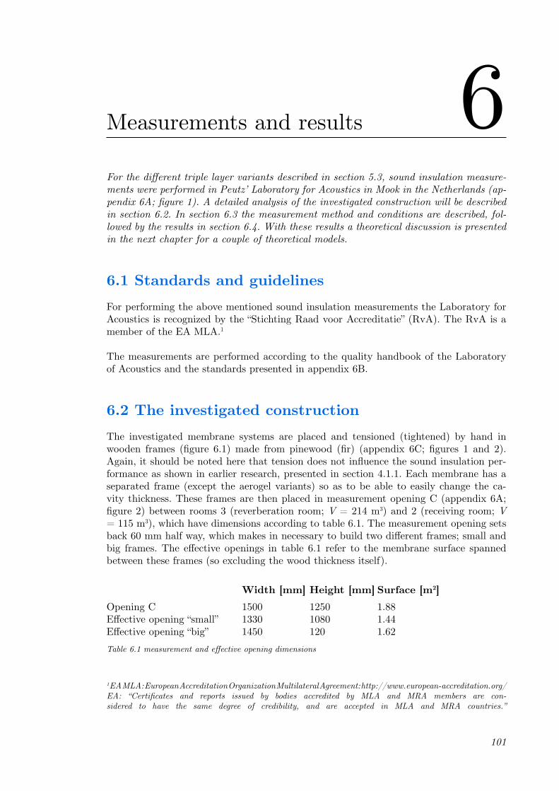
101
Measurements and results 6For the different triple layer variants described in section 5.3, sound insulation measure-ments were performed in Peutz’ Laboratory for Acoustics in Mook in the Netherlands (ap-pendix 6A; figure 1). A detailed analysis of the investigated construction will be described in section 6.2. In section 6.3 the measurement method and conditions are described, fol-lowed by the results in section 6.4. With these results a theoretical discussion is presented in the next chapter for a couple of theoretical models.
6.1 Standards and guidelinesFor performing the above mentioned sound insulation measurements the Laboratory for Acoustics is recognized by the “Stichting Raad voor Accreditatie” (RvA). The RvA is a member of the EA MLA.1
The measurements are performed according to the quality handbook of the Laboratory of Acoustics and the standards presented in appendix 6B.
6.2 The investigated constructionThe investigated membrane systems are placed and tensioned (tightened) by hand in wooden frames (figure 6.1) made from pinewood (fir) (appendix 6C; figures 1 and 2). Again, it should be noted here that tension does not influence the sound insulation per-formance as shown in earlier research, presented in section 4.1.1. Each membrane has a separated frame (except the aerogel variants) so as to be able to easily change the ca-vity thickness. These frames are then placed in measurement opening C (appendix 6A; figure 2) between rooms 3 (reverberation room; V = 214 m3) and 2 (receiving room; V = 115 m3), which have dimensions according to table 6.1. The measurement opening sets back 60 mm half way, which makes in necessary to build two different frames; small and big frames. The effective openings in table 6.1 refer to the membrane surface spanned between these frames (so excluding the wood thickness itself).
Width [mm] Height [mm] Surface [m2]Opening C 1500 1250 1.88Effective opening “small” 1330 1080 1.44Effective opening “big” 1450 120 1.62
1 EA MLA: European Accreditation Organization Multilateral Agreement: http://www.european-accreditation.org/EA: “Certificates and reports issued by bodies accredited by MLA and MRA members are con-sidered to have the same degree of credibility, and are accepted in MLA and MRA countries.”
Table 6.1 measurement and effective opening dimensions
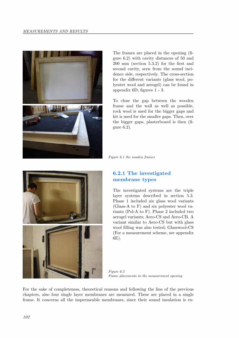
102
Figure 6.1 the wooden frames
The frames are placed in the opening (fi-gure 6.2) with cavity distances of 50 and 200 mm (section 5.3.2) for the first and second cavity, seen from the sound inci-dence side, respectively. The cross-section for the different variants (glass wool, po-lyester wool and aerogel) can be found in appendix 6D; figures 1 - 3.
To close the gap between the wooden frame and the wall as well as possible, rock wool is used for the bigger gaps and kit is used for the smaller gaps. Then, over the bigger gaps, plasterboard is then (fi-gure 6.2).
Figure 6.2 Frame placements in the measurement opening
6.2.1 The investigated membrane types
The investigated systems are the triple layer systems described in section 5.3. Phase 1 included six glass wool variants (Glass-A to F) and six polyester wool va-riants (Pol-A to F). Phase 2 included two aerogel variants; Aero-CS and Aero-CB. A variant similar to Aero-CS but with glass wool filling was also tested; Glasswool-CS (For a measurement scheme, see appendix 6E).
For the sake of completeness, theoretical reasons and following the line of the previous chapters, also four single layer membranes are measured. These are placed in a single frame. It concerns all the impermeable membranes, since their sound insulation is ex-
MEASUREMENTS AND RESULTS

103
Figure 6.3 Upper: Aerogel variant placed in the measurement opening
Wooden slat used for stability of the mats. Lower: Glass wool mats of 10 and
20 mm placed in the frame creating Glasswool-CS.
pected to be higher than that of the per-meable membranes. Also one permeable membrane (no. 3) is tested for mutual comparison. Membranes 4, 5 and 6 (num-bers refer to section 5.2.1) are measured for sound insulation.
• Membrane 3 Perforated fibre glass 410 g/m2 Effective opening “small”• Membrane 4 PVC-coated PES 800 g/m2 Effective opening “small”
• Membrane 5 PVC-coated PES 900 g/m2 Effective opening “small”• Membrane 6 PTFE-coated glass fibre fabric 800 g/m2 Effective opening “big”
6.3 Measurements
6.3.1 Measurement method
The measurements are carried out con-form ISO 140-3 in the insulation measure-ment rooms of Peutz bv in Mook (The Ne-therlands). A more detailed description of those rooms can be found in appendix 6A.
Figure 6.4 Insulation measurements rooms in the Peutz Laboratory.
Hanging and standing baffles for creating a practical achievable diffuse sound field. An automatically
rotating microphone is installed for accuracy.
MEASUREMENT METHOD

104
The sound insulation measurements are carried out in two directions by changing between sending and receiving function. The obtained sound insulation values are an average of both directions.
According to ISO 140-3 the airborne sound insulation of an object is defined by the “sound reduction index R”, which is determined according to equation 6.1 and expressed in dB:
R L L SA
= − +
1 2 10 lg
A VT
=⋅0 16.
(6.1)
, with:L1 = sound pressure level in the sending room [dB]L2 = sound pressure level in the receiving room [dB]S = Surface of the object (here: 1.88 m2)A = equivalent sound absorption [m2] in the receiving room according to:
(6.2)
, where V is the volume of the receiving room [m3] and T the reverberation time of the receiving room [s].
6.3.2 Accuracy
The accuracy of the calculated sound insulation values can be expressed numerically in terms of repeatability (within one laboratory) and reproducibility (between different laboratories).
Repeatability (r)When sound insulation measurements are carried out, with a short interval, using twice the same method on an identical object under equal conditions, the probability is 95% that the difference between the two measurements has a maximum of r.
In order to gain insight in the repeatability of airborne sound insulation measurements between two rooms of Peutz bv, an investigation is carried out in accordance with ISO 140-2. From this investigation it can be concluded that the repeatability in the frequency bands 100 to 250 Hz maximum, r = 2.0 dB and above that, till 3150 Hz maximum, r = 1.3 dB.
The repeatability concerning the single number rating Rw has a maximum of r = 0.7 dB, so that with rounding to whole dB’s (ISO 717) it can be assumed that the repeatability is 1 dB.
From these measurement results it becomes clear that the repeatability complies (to a high degree) with the requirements in ISO 140-2.
±
MEASUREMENTS AND RESULTS

105
Reproducibility (R)When sound insulation measurements are carried out twice with a short interval, using the same method on an identical object under equal conditions, the probability is 95% that the difference between the two measurements has a maximum of R.
Partly based on various investigations, ISO 140-2 indicates which reproducibility can be expected. The reproducibility of the single number rating Rw is approx. R = 3 dB.
6.3.3 Environment conditions
The environment conditions, which are true during all sound insulation measurements, are shown in table 6.2.
Room Temperature [oC] Relative humidity [%]2 19,2 583 19,2 57Table 6.2 Environment conditions during the measurements.
6.3.4 Results
Single layer membranesThe results of four single layer membranes are given in figure 6.5 below.
RESULTS
Measurementsfreq M4 M5 M6 M3/perm
100 3 4 3,6 3,7125 4,6 4,3 4,7 4,4160 6,2 5,5 6 5200 5,1 5 5,1 4,2250 6,2 5,4 6,1 2,7315 7 6,5 6,8 2,8400 8,6 8 8,3 3500 9,9 10 9,3 3,1630 11,3 11,5 10,6 3800 12,8 12,7 12,3 3,7
1000 14,5 14,6 13,9 3,81250 15,3 15,6 14,7 3,81600 16,2 17,1 15,6 3,92000 17,9 18,8 17,1 3,72500 20,1 20,8 19,2 3,73150 21,8 22,6 20,9 3,84000 23,1 24 22,2 3,95000 25,4 26,4 24,8 3,8
0
5
10
15
20
25
30
100
125
160
200
250
315
400
500
630
800
1000
1250
1600
2000
2500
3150
4000
5000
Airb
orne
Sou
nd I
nsul
atio
n [d
B]
Measurement results single layer membranes
Perforated fibreglass
PVC-coated PES (800 g/m2)
PVC-coated PES (900 g/m2)
PTFE-coated fibreglass (800 g/m2)
Frequency [Hz]
Fig. 6.5 Measurement results for the single layer membranes. The impermeable membranes have a Rw of 14 dB and the permeable membrane 4 dB. Refer to Appendix 6F for the measurement data.
Measurement results single layer membranes
106
MEASUREMENTS AND RESULTS
The three impermeable membranes do not differ much. Especially at low frequencies the airborne sound insulation is mostly the same. At higher frequencies (above 1 kHz), the heavier PVC-coated PES membrane performs best. This is probably due to the higher mass, but the difference is negligible. Furthermore, it can be seen that the PVC-coated PES with the same mass as the PTFE-coated fibreglass performs a little better than the fibreglass. But differences are very small and again negligible.
The small decrease which can be seen at around 200 Hz might be due to the diffusiveness of the measurement room. Since the wave lengths of the sound waves at low frequencies are quite long, the dimensions of the measurement room can play a part in the accuracy. Furthermore, values at low frequencies are unreliable because of the low amount of reflec-tions in a (here: small) room. For Sabine’s formula for the reverberation time, a minimal amount of reflections are required to create the best possible approximated diffuse sound field. This is illustrated by equation 6.3.
N V f fc
= 42
03π∆
(6.3)
, where N is the amount of reflections and V is the volume of the room. It shows clearly that when f or V decreases, N decreases. This is why low frequency (here: up to 200 Hz) results might be unreliable. Apart from this, all three impermeable membranes describe a very straight line.
The sound insulation of the perforated fibreglass is around 4 dB for all frequencies and is thus very low. This is obvious, because there is barely anything that is stopping the sound energy if there are perforations in the measured object.
Triple layer systemsFor all triple layer systems of phase 1 (glass and polyester wool variants) the results are given in figure 6.6 and 6.7 below. The glass and polyester wool variants are separated be-cause of clarity in the graphs. Subsequently, in figure 6.9, a comparison is made between the four best results of the glass and polyester wool variants. This figure includes the measurement results of the aerogel variants, but these are also separately shown in figure 6.8.
As a reference the insulation values for a double glazing panel (6-12-6 mm) and a stone wall of 200 kg/m2 are presented as a black dotted line and black dashed line respectively. Values are from the program BO.A’s (version 4.4.6) database.
Figures 6.6 and 6.7 show that the variants C and F, for both glass and polyester wool, perform best in airborne sound insulation. This can be explained by the fact that variants C and F have three impermeable membranes, whereas the rest of the variants have a per-meable (perforated or mesh) membrane on sound incidence side. The rest of the variants perform slightly worse, but quite similar to each other. From 500 Hz and higher a signifi-cantly difference can be seen between variants C and F and the rest, up to almost 10 dB.

107
RESULTS
Measurement results Triple-layer membrane configurations
Measurement nr. #1 #2 #3 #4 #5 #6 #7Frequency 1/1 oct Glass-A Glass-B Glass-C Pol-A Pol-B Pol-C Glass-D
100 8,5 7,4 7,7 6,1 7,2 7,3 6,8125 12,6 12,6 13,8 10,3 11,6 12,9 11,1160 14,6 14,7 15,9 12,1 13,3 14,3 14,4200 17,6 17,5 18,6 14,3 15,2 16,6 17250 20,1 20,9 21,7 17,3 18,2 19,3 20,4315 22,8 24,6 24,8 20,9 21,7 22,5 24,7400 27,4 29,1 30,3 25,5 26,3 26,9 29,4500 32,6 33,5 37,4 29,2 30,1 33 34,1630 37,8 39,2 45,4 32,7 33,9 39,7 39,5800 44,3 45,7 55,1 37,5 38,8 47,6 45,9
1000 51,1 52,8 63,4 42,9 44,9 55,4 52,91250 58,3 59,9 68,6 48,5 50,6 63,1 59,71600 64,7 66,4 74 53,7 56,1 69,1 66,22000 69,8 71,3 75,6 58,8 61,2 73,3 71,42500 71,3 71,9 73,2 64 66 72,8 72,83150 71,1 70,3 70,3 66,7 67,7 69,9 69,84000 64,9 64,9 65,2 64,1 64,1 64,5 64,15000 60,6 61,8 61,8 61,7 61,8 62,1 61,7
0
10
20
30
40
50
60
70
80
Airb
orne
Sou
nd In
sula
tion
R [d
B]Measurement results glass wool variants
Glass-A
Glass-B
Glass-C
Glass-D
Glass-E
Glass-F
Double glass panel (6-12-6)Stone wall (200 kg/m2)
Frequency [Hz]Fig. 6.6 Measurement results for the triple layered glass wool variants. The single number
rating Rw of these triple layer systems is 32-33 dB. Refer to Appendix 6F for the measurement data.
Fig. 6.7 Measurement results for the single layer membranes. The single number rating Rw of these triple layer systems is 29-32 dB. Rrefer to Appendix 6F for the measurement data.
0
10
20
30
40
50
60
70
80
Airb
orne
Sou
nd I
nsul
atio
n R
[dB
]
Measurement results polyester wool variants
Pol-A
Pol-B
Pol-C
Pol-D
Pol-E
Pol-F
Double glass panel (6-12-6
Stone wall (200 kg/m2)
Frequency [Hz]
Measurement results polyester wool variants
Measurement results glass wool variants

108
Around approx. 2 kHz, the sound insulation of all variants decreases drastically. This is mainly due to the end of the dynamic range (air absorption between 2 and 4 kHz is only about 1.5 dB). The sources in the sending room are not totally flat, which gives diffe-rences in the receiving room of approx. 10 dB between 2 and 4 kHz, while the receiving level reaches the end of the dynamic range of 60 dB, as well as to the noise itself. For this reason, the measurement results after 2 kHz are for this reason not reliable. From 2 kHz the results are dotted in the figures. This can be solved by using two ranges and thus performing each measurement in two sessions. Due to lack of time, this was not done during this research.
In general can be said that the airborne sound insulation for these triple-leaf systems is quite good, especially for mid and high frequencies. At low frequencies these systems perform not that good, which is the main issue for lightweight structures. The main focus in especially chapter 8 shall be the lower frequency range.
Figure 6.8 shows the measurement results for the aerogel variants and the equal sized mineral wool variant (Glasswool-CS). For comparison one of the better performing glass wool variants (Glass-C) is presented as well.
0
10
20
30
40
50
60
70
80
Airb
orne
Sou
nd I
nsul
atio
n R
[dB
]
Measurement results aerogel variants
Aero-CSGlasswool-SAero-CBGlass-C
Frequency [Hz]
5 6 6
Aero-CS
CS
5 6 6
Glass-C
C
5 6 6
Glasswool-CS
CS
5 6 6
Aero-CB
CB
Fig. 6.8 Measurement results for the aerogel systems Aero-CS (Rw = 24 dB) and Aero-CB (Rw = 29 dB). For comparison the aerogel in the Aero-CS variant is replaced by mineral wool; hence the Glasswool-CS (Rw = 23 dB) variant. Please refer to Appendix 6F for the measurement data.
MEASUREMENTS AND RESULTS
The Aero-CS variant is the variant with the three impermeable membranes (on front the PVC-coated PES and second and third the PTFE-coated fibreglass) and the small (“S”) cavity sizes. Aero-CB is the same membrane type variant, except for bigger (“B”) cavity sizes. This is more comparable to the glass and polyester wool variants (250 mm cavity
Measurement results aerogel variants

109
RESULTS
in total). Glasswool-CS is the same system as Aero-CS, only then filled with glass wool (different glass wool then the rest of the research, with a different flow resistance).
First, in figure 6.8, the Aero-CS can be compared to the Aero-CB variant. Up to 200 Hz the CS variant performs a little better, around the 4-5 dB. From there on the CB variant performs mostly 15 dB better than the CS variant, which is significant. The same applies to low frequencies as discussed before. Due to the size of the measurement room, the re-sults at low frequencies can be deceiving. The fact that the CS variant performs a little better below 200 Hz is not very meaningful. This can be generally said for all results in the (very) low frequency range.
Second, the Aero-CS variant can be compared to the same variant but instead of aerogel the cavities are now filled with glass wool. This Glasswool-CS variant performs almost the same up till 630 Hz. But from there on, to 3150 Hz (it should be noted again, that the measurement results are not reliable above 2 kHz as mentioned before), the mineral wool performs significantly better than the aerogel. Moreover, the Glasswool-CS measu-rement results are very high compared to the results gained with the MLM (the model predicts the other variants quiet well; section 7.2.1). The reason for this discrepancy between measurement and theoretical results is not clear. The measurement results or the computed MLM results may be unreliable for this variant. Conclusions should therefore be carefully drawn.Thirdly, all three above mentioned variants (triple layer) perform less than the Glass-C variant (solid black line in the graph) in the entire frequency range. Best comparable is the Aero-CB variant, since both cavities have the same thicknesses as the (normal) glass wool variants. Difference is that Glass-C is fully filled with glass wool and the Aero-CB only for a small part (30 from 250 mm in total). This difference is probably the reason for the performance difference, especially at mid and high frequencies for that is charac-teristic for porous absorption materials.
However, comparing Glass-C to an aerogel variant where the entire cavity of 250 mm is filled with aerogel (using the MLM), gives better sound insulation values for the aerogel variant, theoretically. To be sure, measurements should be carried out. The main dif-ferences in sound insulation in figure 6.8 are caused by the different cavity thicknesses.
In figure 6.9, the four systems for the glass- and polyester wool variants, which are totally impermeable (variants C and F), are compared. At the same time the four best results, as can be seen from figures 6.6 and 6.7. Both of the aerogel variants are repeated here as well. Now, only the results up to 2 kHz are presented, since the results are not reliable above that frequency, as mentioned before.
Figure 6.9 shows, that the glass wool variants are the best performing variants, in terms of airborne sound insulation. It can be concluded from this that glass wool is better sound insulating than polyester wool in this research, when only taking these measurements, and not practical matters, into account. An explanation can be found in the characteris-tics of porous absorbers.
Characteristics of porous absorbersThere are several parameters which influence the absorption (and thus sound insulation

110
MEASUREMENTS AND RESULTS
0
10
20
30
40
50
60
70
80
100 125 160 200 250 315 400 500 630 800 1000 1250 1600 2000
Aire
born
e So
und
Insu
latio
n R
[dB
]
Measurement results impermeable glass- and polyester wool variants and aerogel variants
Glass-C
Glass-F
Pol-C
Pol-F
Aero-CS
Aero-CB
Frequency [Hz]
Fig. 6.9 Measurement results for the four (glass- and polyester wool) impermeable systems and the two aerogel variants. Refer to Appendix 6F for the measurement data.
5 6 6
Aero-CS
CS
5 6 6
Glass/Pol-C
C
5 6 6
Aero-CB
CB
4 4 5
Glass/Pol-F
F
Measurement results impermeable glass- and polyester wool variants and aerogel variants
here) when using porous absorption materials (see also section 2.2.4). Namely; flow resis-tance, layer thickness (relation to mass), frequency, pore structure, porosity (percentage of air content; relation to mass) and manner of fixation [1]. From these, the main cha-racteristic parameters are the (volume) porosity and pore structure (usually taken under the same heading) and flow resistance. The volume porosity is the ratio of air volume contained in the porous material to the total volume [2]:
σ ρρv
a
m= −1
ρa ρm
χ
χ σσ= v
s
(6.4)
, where is the bulk density of the material and the density of the matrix material (mineral fibre materials: 2250 kg/m3). The volume porosity for mineral fibre materials ranges from 0.92 to 0.99 (mineral fibre wool ranges from 0.95-0.99 [3]). From these values the bulk density can be calculated. With the bulk density the flow resistivity can be cal-culated with empirical formulas [4, 5].
The most ambiguous parameter describing the pore structure is the structure factor , defined in the ‘quasi-homogeneous material’ theory as:
(6.5)
111
REFERENCES
σ s, where is the surface porosity of a cut through material. Its value depends on the pore shapes. This parameter is too detailed to get into in this research any further.
For the flow resistance theory section 2.1.4 can be studied. In order to describe the dif-ference between the glass and polyester wool variants, the flow resistance is measured for these materials (as well as for the aerogel). The results are presented in Appendix 6G. Glass wool has a (specific) airflow resistance of 638 Ns/m3 (averaged over three samples), polyester wool 127 Ns/m3 and aerogel 1389 Ns/m3. It means that glass wool is more re-sistant to airflow through the material than polyester wool.
Glass or polyester woolTo give any further conclusions, two views should be distinguished. The first is from a room acoustical point of view, where absorption is, in fact, absorption plus transmission and where reflection is not desirable (except when reflectors are the goal). The second is from a sound proofing point of view, where absorption and reflection are desirable since less transmission is the result. Here only the second view is discussed, because this is the subject of this research (for the room acoustical view; section 8.1.1). In that case sound energy that is not transmitted is favourable, so that the higher the flow resistance, the better the sound insulation. Since the lightweight glass wool has a higher flow resistance than polyester wool, the sound insulation is higher, which is shown in figure 6.9 (optimi-sation of the flow resistance; section 8.2.1).
For a more thorough analysis of the aerogel variants, refer to sections 7.2.5 and 8.2.1.
In the next chapter a theoretical validation will be presented in relation to variants Glass-A, Glass-C and Pol-C only. Glass-C performed best (and equally well as Glass-F) and Glass-A is one of the variants with a permeable membrane. Pol-C had the same mem-brane configuration as Glass-C, but the (specific) airflow resistance differs for the filling material as described above. A comparison can be valuable.
References1. Nederlof, L. & Cauberg, J.J.M. (2005), A-5; Absorptiemechanismen, Kennisbank Bouwfysica2. Mechel, F.P. (2008), G - Porous Absorbers in Formulas for Acoustics, Springer International Publisher3. Hopkins, K. (2007), Sound insulation, First Edition, published by Elsevier Science Publishers Ltd.4. Bies, D.A. (1988), Acoustical properties of porous materials, In Beranek, L.L (ed.), Noise and Vibration control, Washington, DC. Institute for Noise Control Engineering, 245-269, ISBN: 09622072095. Nichols, R.H. (1947), Flow-resistance characteristics of fibrous acoustical materials, Journal of the Acoustical Society of America, Vol. 19 (5), 866-871


113
Theoretical validation 7Based on the experimental results obtained during the measurements, described in the pre-vious chapter, in this chapter a comparison is made between those results and theoretical models. A distinction can be made between the single layer membranes in section 7.1 and the triple layer systems in section 7.2. The single layer membrane measurement results are compared to the mass law for diffuse incidence, the advanced mass law model and to the formulas according to the NEN-EN 12354-1. The triple layer membrane results (for Glass-A, Glass-C and Pol-C) are compared to conventional formula for triple-leaf sys-tems, the theoretical model described by Sakagami, and the computational results from the Multiple Layer Model. In additon to this, a comparison is made between the double layer systems from De Geetere and the triple-leaf systems from this research, in section 7.3.
7.1 Single layer membranesFor single layer (homogeneous) walls a number of theoretical models are available. Here, four theoretical models are compared to the measurement results of the single layer membranes. The mass law for normal incidence, the mass law for diffuse incidence, the advanced model by Nederlof & Cauberg [1] and the formulas according to the NEN-EN 12351-1.
Mass lawThe mass law for normal incidence used here is equation 2.9 in section 2.2.1. For the mass law for diffuse incidence, equation 2.9 is modified by dividing by . In figures 7.1-3 this comparison is made.
Advanced model by Nederlof & CaubergMore advanced mass law models are quoted in literature. An example, used in this re-search, is the model by Nederlof & Cauberg [1], described by equation 2.14 in section 2.2.1. This model takes the effects of coincidence into account. Again, an angle of inci-dence of 56o is used. In figures 7.1-3 this comparison is made.
Formulas according to the NEN-EN 12354-1Another approach is described in the NEN-EN 12354-1 and was first derived by Gerritsen [2]. Equation 2.11 in section 2.2.1 gives the transmission coefficient for three frequency ranges. The radiation factor for resonant transmission in eq. 2.11 is derived by Lepping-ton et al. [3] and presented in equation 2.13. The non-resonant radiation factor is derived by Sewell [4] is described according to equation 2.12. In figures 7.1-3 this comparison is made.
ωm 2 30 0ρ c
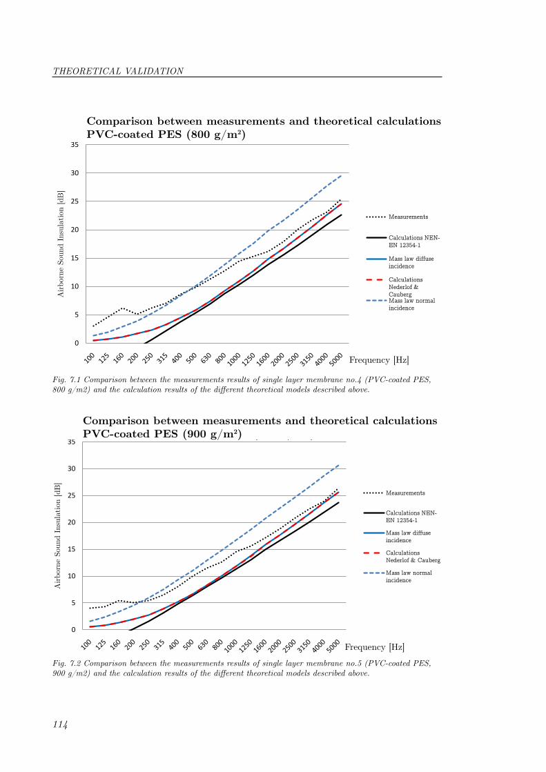
114
VOERD! Massa goed invoeren!
0
5
10
15
20
25
30
35
Airb
orne
Sou
nd I
nsul
atio
n [d
B]
Comparison measurements and theoretical calculationsPVC-coated PES (800 g/m2)
Measurements
Calculations NEN-EN 12354-1
Mass law diffuse incidence
Calculations Nederlof & CaubergMass law normal incidence
Frequency [Hz]
Fig. 7.1 Comparison between the measurements results of single layer membrane no.4 (PVC-coated PES, 800 g/m2) and the calculation results of the different theoretical models described above.
Comparison between measurements and theoretical calculationsPVC-coated PES (800 g/m2)
0
5
10
15
20
25
30
35
Airb
orne
Sou
nd I
nsul
atio
n [d
B]
Comparison measurements and theoretical calculationsPVC-coated PES (900 g/m2)
Measurements
Calculations NEN-EN 12354-1
Mass law diffuse incidence
Calculations Nederlof & Cauberg
Mass law normal incidence
Frequency [Hz]
Fig. 7.2 Comparison between the measurements results of single layer membrane no.5 (PVC-coated PES, 900 g/m2) and the calculation results of the different theoretical models described above.
Comparison between measurements and theoretical calculationsPVC-coated PES (900 g/m2)
THEORETICAL VALIDATION

115
0
5
10
15
20
25
30
35
Airb
orne
Sou
nd I
nsul
atio
n [d
B]
Comparison measurements and theoretical calculationsPTFE-coated fibre glass (800 g/m2)
Measurements
Calculations NEN-EN 12354-1
Mass law diffuse incidence
Calculations Nederlof & Cauberg
Mass law normal incidence
Frequency [Hz]
Fig. 7.3 Comparison between the measurements results of single layer membrane no.6 (PTFE-coated fibre glass, 800 g/m2) and the calculation results of the different theoretical models described above.
Comparison between measurements and theoretical calculationsPTFE-coated fibre glass (800 g/m2)
Discussion and conclusionThe measurements of the impermeable membranes (figures 7.1-3) are quite well described by the models of Nederlof & Cauberg as well as by the mass law for diffuse incidence. The difference is approx. 3 dB at its maximum in the lower frequency range. The slopes of the measured and theoretical curves differ though. The curves of both models have a higher slope than the curve of measurements, which can be seen in the graphs. The mass law for normal incidence describes the measurement results a little better at lower frequencies, but gives too high sound insulation values from 500 Hz on.
The fact that the mass law for diffuse incidence and the advanced model according to Nederlof & Cauberg are similar in above cases is due to the fact that the advanced model describes the coincidence effect as well. No coincidence is seen in the measurements in this frequency range. It occurs far above 5 kHz according to the models. Furthermore the Young’s modulus is of influence in this case. When this value is a factor ten higher (9*109 instead of 0.9*109 N/m2) the model of Nederlof & Cauberg starts to decrease, unlike the mass law, around 3000 Hz. Thus, coincidence will occur at a lower frequency when the Young’s modulus is higher.
It is worth noting that the formulas in the NEN-EN 12354-1 have the same slope as the measurements from the mid frequency range on. This line however, crosses an airborne sound insulation of 0 dB at 200-250 Hz (for the impermeable membranes), which is practically impossible. This is due to the shape factor incorporated in this model, which ranges from 0 to 0.5 [4]. When playing with this shape factor a more fitting curve can be
SINGLE LAYER MEMBRANES

116
created, so it might be that the shape factor is derived for thick plates and is not useful for membranes.
It can be concluded that both the advanced model and the model for diffuse incidence describe the measurements best. For an empirical formula the mass law for diffuse in-cidence can be modified by adding 3 dB (purely empirical) for single-leaf, impermeable membranes, hence equation 7.1.
R mc
= +
+10 1
2 33
0 0
2
log ωρ
dB (Single-leaf, imperrmeable membranes)
This modified equation is shown in figure 7.4 for membranes 4 and 5. Membrane 6 is comparable to the left figure.
(7.1)
S ZIJN INGEVOERD!
0
5
10
15
20
25
30
Single-layer membrane 4 (PVC-coated polyester 800 g/m2)
Measurements Mass law diffuse + 3dB
0
5
10
15
20
25
30
35
Single-layer membrane 5 (PVC-coated polyester 900 g/m2)
Measurements Mass law diffuse + 3dB
Airb
orne
Sou
nd I
nsul
atio
n [d
B]
Comparison measurements between left PVC-coated PES (800 g/m2) and right PVC-coated PES (900 g/m2) and the empirical mass law according to eq. 7.1
Fig. 7.4 Empirical modified mass law for diffuse incidence for single-leaf, impermeable membranes compared to the measurement results of membranes no.4 and 5.
None of the theoretical models for single, homogeneous walls describe the permeable membrane well, since all assumptions made in the models do not match a perforated or permeable membrane (theoretical models for composed walls do not describe a permeable leaf either). No parameter is available to describe the degree of permeability in these “common” models. Some models referred to in section 3.1.1, especially that of Takahashi et al., describes single-leaf, permeable membranes. Since this research’s focus is on triple-leaf membranes no further comparison is made here.
7.2 Triple layer membrane systemsThe results for the triple layer membrane measurements (Glass-A, Glass-C and Pol-C) are theoretically discussed according to three different theoretical models. First the Mul-tiple Layer Model by Nijs is discussed in section 7.2.1. Then the (conventional) equations for triple-leaf systems by Vinokur are described in section 7.2.2, followed by the theore-tical model of Sakagami in section 7.2.3. These theoretical models are compared to the
THEORETICAL VALIDATION

117
measurement results in the figures 7.5-7. The comparison is discussed in section 7.2.4. This section closes with the comparison between the measurement results of the aerogel variants and the computational results of the MLM in section 7.2.5.
7.2.1 Multiple Layer Model
The Multiple Layer Model (MLM) [5] is described by Nijs [6, 7] in section 2.2.2. In Ap-pendix 7A the input file for the variants Glass-A, Glass-C and Pol-C are presented. The program only runs the lines without a slash in front, the rest is information.
The lightweight glass wool (except for variant Glasswool-CS) used in this research has an airflow resistivity of 6400 Ns/m4 (averaged over three samples), polyester wool 1300 Ns/m4 and aerogel 138900 Ns/m4 (Appendix 6G; measurements carried out for this re-search). The Poisson ratio is arbitrary since membrane material is in fact a weave which has different Poisson ratios for each direction, but since only one value can be used in the model, 0.3 is chosen (for the permeable membrane a slightly smaller Poisson ratio is chosen; 0.25). The elastic moduli for coated membranes differ for the warp and fill di-rection (like the Poisson ratio) and Galliot and Luchsinger [8] and Gosling [9] performed numerous tests to validate this. The elastic modulus of Verseidag (Duraskin®) membrane materials is around 900 kN per meter width averaged for the warp and fill direction. Since the quantity should be entered per square meter, a membrane thickness of 1 mm gives a value of 0.9 GPa (=106 kN/m2). For the permeable membranes the same value holds true.
In figures 7.5-7 the comparison between the measurement results of variants Glass-A, Glass-C and Pol-C and the calculated MLM results for these variants is presented. The MLM is calculated using diffuse incidence to compare best with the measurement results, but also calculated using oblique incidence with an angle of incidence of 60o to compare with Sakagami’s and the triple-leaf model.
7.2.2 Conventional formula for triple-leaf systems
Some theoretical research has been done into triple-leaf systems in the past. One example, which is discussed in section 2.2.1, is the formula by Vinokur [10]. In figures 7.5-7 the comparison between the measurement results of variants Glass-A, Glass-C and Pol-C and the calculation results using equation 2.36 is presented.
7.2.3 Sakagami’s triple-leaf model
Theoretical research into the sound insulation of triple-leaf membrane systems has been done by Sakagami [11]. Refer to section 3.2.4 for a more thorough background. To compa-re his triple-leaf model to the measurement results, the model had to be modified to one where all three membranes are impermeable and one where the leaf on sound incidence side is permeable (refer to section 3.2.4 and Appendices 3A and B for the derivation).
For a triple-leaf system with a permeable leaf on sound incidence side, the flow resistance Rh is used by Sakagami. According to [12, 13] this parameter cannot be calculated for membrane materials and should be measured accordingly. In this research the flow resis-
SAKAGAMI’S TRIPLE-LEAF MODEL

118
THEORETICAL VALIDATION
VinokurGlass-A
2,052,613,1
3,162,4
0,664,16
10,8515,1112,8622,1334,6638,5945,3
61,9364,69
7469,880
20
40
60
80
100
120
140
Airb
orne
Sou
nd I
nsul
atio
n [d
B]
Glass-A
Measurements
Calculation results Sakagami
MLM Diffuse
MLM 60grad
Calculation results Vinokur
Calculation results mass law (single layer)
Frequency [Hz]
Figure 7.5 The measurements of the triple layer system Glass-A compared the calculation results of the theoretical models.
Comparison between measurements and theoretical calculationsfor triple-leaf system Glass-A
1 6 6
Glass-A
A
tance for the membranes is not measured and for above model a flow resistance value of 3000 Ns/m3 is adopted from different papers [11-13], which gives reasonable agreement with the measurement results. The rest of the parameters are modelled as described in section 3.2.4 and Appendices 3A and B.
In figures 7.5-7 the comparison between the measurement results of variants Glass-A, Glass-C and Pol-C and calculation results of the triple-leaf models by Sakagami is pre-sented.
Reliable range
7.2.4 Discussion and conclusions for the triple-leaf systems
The range between the vertical dotted lines is most reliable for the measurement results. Below 200 Hz the (lack of) diffusiveness in the measurement room starts to play a role and above 2000 Hz the limited dynamic range results in unreliable measurement results as both explained before.
Both the calculation results of Sakagami’s model and that of Vinokur predict some dips due to mass-spring and cavity resonance, which can be concluded from the erratic course of the curves. Since the cavity is modelled as a spring containing air in Vinokur’s mo-del, whereas in Sakagami’s model the cavity only contains air, the resulting curve is not smooth. Despite this, Sakagami’s model describes the measurements better than Vino-kur’s model. Research should be carried out to modify both theoretical models into ones

119
DISCUSSION AND CONCLUSION FOR THE TRIPLE-LEAF SYSTEMS
VinokurGlass-C
2,322,913,43,42,5
0,885,46
11,8515,328,61
26,3637,5741,0847,6564,1966,8976,1772,01
0
20
40
60
80
100
120
140
Airb
orne
Sou
nd I
nsul
atio
n [d
B]
Glass-C
Measurements
Calculation results Sakagami
MLM Diffuse
MLM 60grad
Calculation results Vinokur
Calculation results mass law (single layer)
Frequency [Hz]
Fig. 7.6 The measurements of the triple layer system Glass-Ccompared the calculation results of the theoretical models.
Comparison between measurements and theoretical calculationsfor triple-leaf system Glass-C
5 6 6
Glass-C
C
ad
0
20
40
60
80
100
120
140
Airb
orne
Sou
nd I
nsul
atio
n [d
B]
Pol-C
Measurements
Calculation results Sakagami
MLM Diffuse
MLM 60grad
Calculation results Vinokur
Calculation results mass law (single layer)
Frequency [Hz]
Figure 7.7 The measurements of the triple layer system Pol-C compared the calculation results of the theoretical models.
Comparison between measurements and theoretical calculationsfor triple-leaf system Pol-C
5 6 6
Pol-C
C
Reliable range
Reliable range

120
which can also predict the consequences of different kinds of filling material.
The calculated results using the MLM, diffuse as well as oblique (56o), gives the best match with the measurement results. Between these two modelling options appears not to be much difference. This proves the fact that diffuse incidence can be approximated with oblique incidence with an angle of incidence of 56o. Compared to both other theoretical models, the MLM is modelled with filling material in its cavities and this might partly explain the better result. The MLM also incorporates damping, which Sakagami’s and Vinokur’s model do not. Other factors might play a part here as well.
To demonstrate that triple-leaf membrane systems do have higher sound insulation than single-leaf membranes, the calculated mass law results for a single membrane (PVC-coated PES) are presented in figures 7.5-7 as well. Especially for mid and high frequencies triple-leaf systems perform better, and at a frequency of 200 Hz the difference is already more than 10 dB between to two systems.
Multiple Layer ModelThe MLM describes the measurement results (very) well up to around 1 kHz for Glass-A and Glass-C and 2 kHz for Pol-C. After that, the measurement results are not reliable anymore and thus no conclusion can be given there. The same holds for frequencies below 200 Hz. The Multiple Layer Model is used in further chapters and sections as the model describing the measurement results best and an optimisation of the triple-leaf systems is done in chapter 8 using the MLM. It should be noted however that this only holds true in the reliable range between 200 and 2000 Hz. Outside this range the model should be verified with measurements first, e.g. by using multiple dynamic, measurement ranges.
Vinokur’s conventional formulaIn all cases conventional formula of Vinokur predicts a lower air-borne sound insulation than measured. Up to 20 dB difference at most frequencies. The multiple dips in the curve are mentioned before. As a simplification can be said that for a filled cavity (with fibrous absorbent material) these dips can be ignored and a more smooth line may be drawn through the calculation results. This curve than slopes and has the same shape as the curve for the measurement results or MLM results, but gives lower sound insulation values.
The reason that this model gives low results might be due to the assumptions made, like a sample of infinite extent and masses of infinite bending stiffness. Another reason for this difference for triple-leaf membranes might be that when the cavity is filled, the entire system of cavities plus membranes acts differently to a system of masses with infinite ben-ding stiffness. It might be acting more like one big, lump mass. And again, no damping is incorporated here (friction in the filling material). And thus the simplification made in the preceding paragraph on ignoring the dips might be wrong. To give a good conclusion here, more research should be done into the origin of Vinokur’s formula.
Sakagami’s triple-leaf systemWhat stands out is all the oscillations the curves describe for all three variants. This is caused by the cavities being empty as mentioned before. At 200-250 Hz and 500 Hz, dips occur, caused by mass-spring resonance and cavity resonances (standing waves in the
THEORETICAL VALIDATION

121
THE AEROGEL VARIANTS
cavity) can be observed at 1 and 2.5 kHz. The same holds for Vinokur’s model here; the curve can be smoothened by modelling a cavity filling material.Apart from the dips the model with the permeable leaf on sound incidence side (figure 7.5) predicts the measurement results quite well. The decreasing sound insulation after 1.5-2 kHz is strikingly similar to the measurements (even when the measurement results are not reliable after 2 kHz). For the impermeable membranes (figures 7.6 and 7.7) the same holds true, but instead of decreasing at higher frequencies the Sakagami models pre-dicts increasing sound insulation values. The curve is in that frequency range even steeper than the MLM computational results. When expanded with options to incorporate filling materials, this model might be very promising.
7.2.5 The aerogel variants
To follow up on the discussion in section 6.3.4 concerning the aerogel variants, some extra attention is paid here to these variants. As can be seen in figure 6.8 the measurement results of the aerogel variants are slightly higher than the measurement results of the Glass-C variant at low frequencies. This is not a reliable conclusion, since this phenome-non occurs below 200 Hz. It is still useful in relation to the effect of the flow resistance of a filling material, to compute the aerogel variants with the MLM and compare these with the Glass-C variant for example. Before doing so, figure 7.8 shows the measurement results of the aerogel variant compared to the computational MLM results. Only the re-liable range (200-2000 Hz) is shown here.
0
10
20
30
40
50
60
70
Airb
orne
Sou
nd I
nsul
atio
n R
[dB
]
Measurement results aerogel variants compared to the computed results using MLM
Measurement results Aero-CS
Measurement results Aero-CB
MLM (Aero-CS)
MLM (Aero-CB)
Frequency [Hz]
Fig. 7.8 The measurement results of the aerogel variants compared to the computed results using the MLM for the reliable range only (200-2000 Hz).
Measurement results aerogel variants compared to the computed results using MLM
5 6 6
Aero-CS
CS
5 6 6
Aero-CB
CB

6
8
10
12
14
16
18
63 80 100 125 160 200 250
Airb
orne
Sou
nd I
nsul
atio
n R
[dB
]
Comparison between computed MLM results for Glass-C and Aero-CS
MLM (Aero-CS)
MLM (Glass-C)
122
THEORETICAL VALIDATION
Frequency [Hz]
Fig. 7.9 Comparison between the computed MLM results for the Glass-C and Aero-CS variants at a frequency range of 63-250 Hz. It should be noted that this graph functions only for hypothetical purposes. Conclusions can only be given when verified with measurement results at these lower frequencies.
Comparison between computed MLM results for Glass-C and Aero-CS 5 6 6
Aero-CS
CS
5 6 6
Glass-C
C
The computed MLM results for the Aero-CS variant describe the measurement results quite well, whereas the computed MLM results for the Aero-CB variant has often too low sound insulation values compared to the measurements. In the 250-1000 Hz range this difference is almost 10 dB. And for low frequencies the curve of the computed MLM re-sults rises above the measurement results. Since a tendency can be seen where the sound insulation increases with decreasing frequency starting at around 250 Hz for the Aero-CS variant (measured as well as computed), the lower frequency performance of the aerogel variant might be interesting.
This tendency can be explained by the fact that aerogel might have a high ratio of inter-nal damping to surface density. The general quest for lightweight buildings (especially at low frequencies) is to find a material which exhibits a high internal damping and at the same time a low density. For this, a comparison can be made between variants Glasswool-CS and Aero-CS as depicted in figure 6.8 (section 6.3.4). From 630 Hz on and lower both variants do not differ much, but again it should be noted that the measurement results for the Glasswool-CS variant might be unreliable since the corresponding computed MLM results are significantly lower.
Let’s say that the MLM does describe the several variants well at the lower frequency range. A comparison can be made between the computed MLM results for the Glass-C and Aero-CS variants at low frequencies. This is done in figure 7.9.
Figure 7.9 shows that aerogel might be promising for lower frequencies. To give hard con-clusions the computed MLM results should be verified with measurements.

123
TRIPLE-LAYER MEMBRANES VERSUS DOUBLE-LAYER MEMBRANES
0
10
20
30
40
50
60
70
80
Airb
orne
Sou
nd I
nsul
atio
n R
[dB
]
Measurement results Glass-CDouble 200mm (empty)Double 400mm (filled 50%)
Frequency [Hz]
Figure 7.10 The Glass-C measurement results compared to the measurement results of De Geetere’s double-leaf membrane systems.
Measurement results Glass-C compared to measurement results double-leaf systems De Geetere
5 6 6
Glass-C
C
Double Empty200mm
Double 50% filled400 mm
Reliable range
7.3 Triple-layer membranes versus double-layer membranesL. de Geetere did research, using Contex-T (section 3.3) and measurements, on double leaf membrane systems [14]. In figure 7.10 a comparison is made between a couple of his measurement results and the triple layer measurement results for Glass-C. A good com-parison is difficult, since no good comparable leaf system is measured by De Geetere. Two of his double-leaf systems are compared here; the first with an empty cavity of 200 mm and second a 50% filled cavity of 400 mm.
The double leaf system with a cavity of 200 mm (comparable to the 250 mm of all triple-leaf systems) has an empty cavity. De Geetere did not measure this type with a filled cavity. It is obvious this double-leaf system has lower sound insulation values than the triple-leaf system.
The double leaf system with a cavity of 400 mm (a lot more than 250 mm) is 50% filled with mineral wool for a best comparable system (the thickness of the filling materials match now). The performance is a little better at lower frequencies in comparison to the triple layer system, but this may be due to the additional 200 mm empty cavity and the fact that the mineral wool used was 35 kg/m2. Double as heavy as the light weight glass wool used for the triple layered systems. At higher frequencies (from 630 Hz) the triple layer system performs better.

124
Concluding from these results can be said that triple-leaf membrane systems perform bet-ter in relation to sound insulation compared to double-leaf membranes with comparable thicknesses and filling material. Research, however, shows that double-leaf membrane systems with filled cavities perform better than empty triple-leaf membrane systems. [11]
References1. Nederlof, L., Cauberg, J.J.M., Nijs, L. and Tenpierik, M.J. (??), Architectural Acoustics (03 Single-Leaf Walls)2. Gerritsen, E. (1974), Berekening van de directe en flankerende geluidoverdracht, Stichting Bouwresearch, ’s-Gravenhage3. Leppington, G.G., et al. (1982), The acoustic radiation efficiency of rectangular panels, Proceedings of the Royal Society of London, A382, 245-2714. Sewell, E.C. (1970), Transmission of reverberant sound through a single-leaf partition surrounded by an infinite rigid baffle, J. Sound Vib., Vol. 12, 21-325. Nijs, L. (Windows-version 2000), Het MeerLagenModel – De berekening van de geluidweerstand van een meerlaagse constructie (software program)6. Nijs, L., (2001), Een rekenmodel voor de luchtgeluidisolatie van meerlaagse constructies, Deel 1: theorie plus toepassing op enkelvoudige platen, Bouwfysica, Vol. 12, No.2, 11-16 7. Nijs, L., (2001), De luchtgeluidisolatie van spouwconstructies berekend met een meerlaags rekenmodel, Bouwfysica, Vol. 12, No.3, 9-158. Galliot, C. & Luchsinger, R.H. (2009), A simple model describing the non-linear biaxial tensile behaviour of PVC-coated polyester fabrics for use in finite element analysis, Composite Structures, Vol. 90, 438-4479. Gosling PD. 92007) Tensinet analysis and materials working group – basic philosophy and calling notice, Internet publication http://www.tensinet.com, Tensinews 13, 12–1510. Vinokur, R.Y. & Lalayev, E.M. (1979), Method of calculation of sound insulation of triple sealed windows, Struggle against noise and sound vibration, MDNTP, Moscow, 37-43 (in Russian)11. Sakagami, K. et al. (1999), Acoustic properties of a triple-leaf membrane: a basic study with normal incidence model, Architectural Institute Japan, Vol. 39, 217-22012. Takahashi, D. et al. (1996), Acoustic properties of permeable membranes, J.A.S.A., 99 (5)13. Sakagami, K. et al. (1998), Detailed analysis of the acoustic properties of a permeable membrane, A.A., Vol. 54, No. 2, 93-11114. De Geetere, L. (May 2011), Bouwakoestische prestaties van meerlaagse membraan- systemen, Presentation for the Kennisdag Bouwfysica, Fourth Edition, 20 slides
THEORETICAL VALIDATION


127
Optimisation and practical solutions 8In the preceding chapters the emphasis was on the measurements and theoretical substan-tiation of the triple (and single)-leaf membrane systems. In sections 7.2.1-3 the different theoretical models were compared to the measurements, and in section 7.2.4 a conclusion was presented for that matter. In this chapter, however, the emphasis is on the practical solutions for the triple-leaf system. First, however, the difficulties are discussed and a new problem definition is drafted in section 8.1. In order to overcome the difficulties, section 8.2 includes an optimisation study in the parameters, describing a triple-layer membrane system, and it presents some practical solutions. Which parameters are of influence and how can the system, described in chapter 5, be modified to overcome the difficulties? Ano-ther approach, active noise control, is presented in section 8.3. In section 8.4 the practical solutions are elaborated concerning membrane construction details and assembly procedu-res. Finally, in section 8.5 other aspects are presented.
The range of solutions where membrane products/structures are used is very large. Not all of them are discussed here. The emphasis shall be on tent structures for festivals, but also on roof spans and shortly on pneumatic structures. Again, a lot of possibilities are known to create a membrane tent construction or span, and some are chosen here (introduction of section 8.2) to illustrate the effect of a triple-leaf system as well as possible.
8.1 Problem definitionFrom preceding chapters it can be concluded that a triple-layer membrane system using either glass or polyester wool can be interesting for permanent or temporary membrane structures. Above 250 Hz the (airborne) sound insulation is 20 dB and increasing up to around 65 Hz at 1 kHz. Below 250 Hz, however, the sound insulation is a lot less, which is due to its lightweight character. The low frequency range is the main issue with lightweight structures in general. Since membrane structures are often used for festivals/concerts or musical halls/stadiums, the entire frequency band should be taken into ac-count and especially the lower frequencies. Subwoofers (bass speakers) operate, generally speaking, in the range of 20-200 Hz. These frequencies are usually experienced as most annoying, partly due to the fact that these sound waves penetrate through walls more easily.
For optimising some of the parameters of the triple-leaf system and for finding practical solutions, the lower frequency range is of extra importance. In this chapter, the emphasis will be on the lower frequency range. Since the measurements were only carried out to 100 Hz and below 200 Hz the results are less reliable due to the difficulty of creating a diffuse sound field in a ‘small’ room, the MLM model is used here. This theoretical model describes the measurement results best as seen in the preceding chapter and can calculate to 63 Hz. It is however to quick to say that the MLM describes the lower frequency range well, since no verifications measurements were carried out. To really focus on the lower frequency range, other measurements should be carried out for the triple-layer systems

128
and filling materials. In the following sections some parameters are optimised, as said before, for the best per-forming (in relation to sound insulation) triple-layer system, which is Glass-C. Another conclusion from preceding chapter was that aerogel might be interesting for low frequency sound insulation (not verified yet), so that Aero-CS is optimised in some cases as well. Furthermore, among other things, different filling materials and cavities thicknesses are discussed.
8.1.1 Room acoustical point of view
For giving any useful practical solutions, two views should be distinguished. The first is from a room acoustical point of view, where absorption is in fact absorption plus trans-mission and where reflection is not desirable (except when reflectors are the goal). The second is from a sound proofing point of view, where absorption and reflection are desi-rable since less transmission is the result.
Throughout this research the emphasis and main focus was on the sound proofing/insu-lation part, not on absorption. Measurements were carried out in order to gain insight in the sound insulation values of different kinds of triple-layer membrane configurations, but some configurations also included a permeable leaf on sound incidence side. This leaf is not suitable for sound insulation (more transmission), but it is suiable for absorption. So, if a good room acoustical climate should be realized as well, the configurations using permeable leaf are recommended. The permeability of the membrane provides entrance for the sound waves to be absorbed in the material behind. This system will get worse sound insulation however.
The following sections are about optimisation and finding practical solutions for the best performing membrane configurations in relation to sound insulation. For membrane ma-terial in relation to absorption, see papers on ‘finite size membrane absorbers’.
8.2 Passive solutions“Passive” in this chapter refers to all solutions which are not “active”; active refers to a technique where noise is cancelled out (section 8.3). Passive solutions are all optimisati-ons of parameters or combinations of idea’s regarding the triple-leaf system as a starting point. All passive solutions are focussing on improving the membrane system or the en-tire construction as a whole. Practical solutions can be drawn from this. In section 8.2.1 solutions are presented with respect to the filling material, whereas sections 8.2.2 and 8.2.3 discuss solutions with respect to the membrane itself and the cavity respectively. In section 8.2.4 hybrid constructions, focussing on creating a membrane structure suitable for practice with respect to sound insulation. Pneumatic structures are quite different from other membrane structures, so section 8.2.5 explores the possibilities of a triple-leaf membrane system in combination with air-inflatable structures.
The practical solutions discussed in this chapter (and for this entire research) have some restrictions regarding sound insulation. One of them is that sound leaks may not occur,
OPTIMISATION AND PRACTICAL SOLUTIONS

129
since the smallest gap can make a good solution unusable. Therefore, all membrane struc-tures or tents which only function as open covering or awning are not discussed. In order to get a closed structure, all membrane supports around the edge should be ridged edges, by circular steel sections or neighbouring buildings. Thus, the possibilities discussed in sections 8.2.1-4 are in accordance with the above mentioned assumptions. There are more possibilities still, but in this research the schematic types (excluding pneumatic structu-res) in figure 8.1 are discussed in relation to triple-layer membrane systems [1, 2, 3] (all triple-layer membranes are drawn as one line for clarity).
SOLUTIONS WITH RESPECT TO THE FILLING MATERIAL
Fig. 8.1 Some possibilities for membrane structuresFreestanding festival tents:
a) freestanding highpoint (festival) tent, b) freestanding multi highpoint (festival) tent, c) freestanding flying mast tent (exoskeleton)
Supported structures between neighbouring e.g. buildingsd) highpoint with neighbouring support,
e) multi highpoint (exoskeleton) with neighbouring support, f) ridge-and-valley with neighbouring support and g) simple saddle with neighbouring support (see section 4.1.2 for an explanation on the types)
Freestanding festival tents:
Supported membrane structures
8.2.1 Solutions with respect to the filling material
The filling material used in this research can be optimized or replaced by another mate-rial. This optimisation can be done by changing the flow resistance, bulk density and/or

130
OPTIMISATION AND PRACTICAL SOLUTIONS
pore structure (which is all connected). Replacing the used material by another material is discussed as well, referring to for instance section 5.2.3.
Optimising the used materialOptimizing the used material can be done in different ways. One way is to increase the flow resistance (here: resistivity) of the material. Doing so, the bulk density of the mate-rial (overall mass), increases as well. These are related by the empirical relationship for mineral fibre materials according to [4, 5]:
r kd
bulkk
fibre
=+
11
2
2ρ [Pa.s/m or Ns/m4]
ρbulk d fibre
0 95 0 99. .< <σ v
(8.1)
, where the k’s are constants related to the manufacturing process and the fibre orienta-tion respectively, is the density of the material including pores and is the fibre diameter of the material. In table 8.1 the airborne sound insulation [dB] is calculated using the MLM for variant Glass-C with varying flow resistivity values and corresponding bulk densities. The maximum of flow resistivity is corresponding to the typical (volume) porosity of mineral fibre wool, which is . [6, 7] Using these values gives a range of bulk densities from 22 to 112 kg/m3. Experiments [6] give corresponding flow resistivity’s.
r [Ns/m4] Bulk dens. Total mass 63 125 250 500 1000 Hz [kg/m3] [kg/m2] 6400 16 6.5 8 9.4 16.1 28.8 58.48000 30 10 9.2 10.8 17.3 31.3 61.111000 40 12.5 11.1 12.9 19.5 32.9 65.418000 50 15 15 17.4 24 38.8 73.424000 60 17.5 17.7 20.8 27.4 42.4 79.230000 70 20 20.2 23.7 30.6 45.9 84.636000 80 22.5 22.4 26.5 33.6 49.2 88.644000 90 25 25 29.7 37.4 53.4 92.652000 100 27.5 27.3 32.7 41 57.3 96.8
Table 8.1 The computed airborne sound insulation [dB] with varying flow resistivity’s calculated using the MLM for Glass-C. The corresponding bulk density and total mass of the membrane system is given as well. Only frequencies from 63 to 1 kHz are given, since the emphasis is on the lower frequencies (verification of the MLM on lower frequencies is necessary).
In all probability the values for 63 Hz are unreliable, since the MLM is not verified by measurements yet. This and following tables are for hypothetical purposes only. From table 8.1 it can be concluded that with increasing flow resistivity (and thus bulk density) an increasing (airborne) sound insulation can be achieved. However, in this thesis 7 kg/m2 is the restricted surface density and thus above options are off limits here.
When having to deal with a maximum of 6.5 kg/m2 the different bulk densities give dif-ferent cavity thicknesses. For the combinations in table 8.1, the airborne sound insulation [dB] is calculated using MLM for variant Glass-C in table 8.2.

131
SOLUTIONS WITH RESPECT TO THE FILLING MATERIAL
r [Ns/m4] Bulk dens. Cav.thickness 63 125 250 500 1000 Hz [kg/m3] [mm] 6400 16 50-200 (250) 8 9.4 16.1 28.8 58.48000 30 50-85 (135) 6.3 6.2 8.3 19.7 50.111000 40 25-75 (100) 6.4 6.4 8.2 18.1 42.318000 50 20-60 (80) 7.6 7.3 8 16.9 38.924000 60 20-45 (65) 8.1 7.8 7.3 14.2 36.630000 70 15-40 (55) 8.5 8.2 7.4 13.6 30.736000 80 15-35 (50) 9 8.7 7.6 12.6 29.144000 90 15-30 (45) 9.6 9.2 8 11.5 26.552000 100 15-25 (40) 10 9.6 8.4 10.4 24.3138900 150 10-20 (30) 14.9 13.9 12.3 12.5 22.4
Table 8.2 The computed airborne sound insulation [dB] for different bulk densities (and flow resistivity’s) when the total mass of 6.5 kg/m2 is guaranteed (the last row is the Aero-CS variant with an aberrant total mass of 7 kg/m2). The third column shows the configuration
of cavity thickness modelled in the MLM (verification of the MLM on lower frequencies is necessary)
From table 8.2 it can be concluded that from 250 Hz and higher the (airborne) sound insulation is less with increasing flow resistivity (and bulk density), with equal total mass. But at lower frequencies (where the problem actually lies), it can be seen that when the flow resistivity increases, that after a certain value (24000 Ns/m4) for 63 Hz the sound insulation improves compared to Glass-C (for actual conclusions the MLM should be verified with measurements first). At 125 Hz the sound insulation improves compared to Glass-C from a value of 55000 Ns/m4 or higher, including the aerogel variant (Aero-CS, last row).
Another strategy is to optimize the pore structure for optimal friction. An optimal value can be found because when pores are very wide, the sound insulation is very low and when the pores are very narrow a lot of friction occurs and thus absorption, but the sound waves have more difficulty getting in the material (bad absorption from acoustical point of view, but high sound insulation). Research to the optimal pore structure, and with that flow resistance, without increasing the mass too much is beyond the scope of this research. To adopt the advantages of aerogel (low frequencies) and glass wool (high frequencies) some configurations with both filling materials are calculated using the MLM model (ta-ble 8.3).
Configuration Surface density 63 125 250 500 1k 2k 4k 8kHz[mm] [kg/m2] Glass-C 6.5 8 9.4 6.1 28.8 58.4 87.2 112.8 142.8Aero-CS 7 14.9 13.9 12.3 12.5 22.4 56.5 92.7 124.710 Aero+50 Glass 4.8 9.6 9.1 9 16.6 25.9 59.1 86 112.210 + 100 5.6 10.3 9.9 13.4 23.6 31.4 63.8 95.1 123.910 + 200 7.2 12.3 14.4 21.2 30.6 39.9 76.5 111.4 143.510 + 300 8.8 15.1 19.1 26.7 37.7 48.9 88.4 126.2 191.320 + 100 9.1 13.5 12.9 16 23 41.8 72 104.4 136.520 + 20 7.8 12.6 11.7 9.7 11.3 25.8 59.4 90.9 118.9
Table 8.3 The computed airborne sound insulation [dB] for different configurations of combinations between aerogel and glass wool (verification of the MLM on lower frequencies is necessary)

132
OPTIMISATION AND PRACTICAL SOLUTIONS
As shown in table 8.3 a better performing triple-leaf membrane system can be created using one layer of Spaceloft® (10 mm) in the first cavity and 200 mm of (lightweight) glass wool in the second cavity. But it is not that much better than normal Glass-C. And since the low frequency MLM results are only reliable until they are verified with measurements, no conclusion can be made on which system is better than the other. Recommended is to choose a type according to the project’s budget. Is there more avai-lable, Aero-CS or the 10-200 combination of aerogel and glass wool can be used. Is less available, Glass-C is not a bad choice either. Differences are small.
The combination system with 10 mm aerogel and 200 mm glass wool is used for the de-tails for the practical solutions. Recommended is to use one total package of the system, and so Glass-C can be detailed the same as those details presented in section 8.4.2.
The solutions in figure 8.1 are usually all single-leaf membrane structures. Now, using a triple-layer system, the details are entirely different and the difficulty for erection increa-ses. For details of the triple-layer membrane system (glass wool or aerogel, but cavities of 50 and 200 mm) used at the solutions in figure 8.1, please refer to section 8.4.2.
Different materialOne way to ensure a higher (airborne) sound insulation for especially low frequencies is to replace the current filling material with another material with a higher mass (proba-bly making the membranes heavier or increasing the cavity thickness is more effective). The thicknesses of the cavities in the triple-layer systems in this research are based on a maximum surface density of the entire system of 7-8 kg/m2. The cavity is kept entirely filled in this section. To differ from this rule, means that other filling materials can be used as well, as vertical wall for instance, and some are already discussed in section 5.2.3. Two more soft absorption materials are foam (flexible or not) and felt. Both densities are roughly in the same range as the glass and polyester wool used, so these will not be discussed here.
For a vertical wall where the surface density restriction is not present, water or sand can be a good option, especially for lower frequencies. Since water has more practical disad-vantages like workability and providing a watertight membrane construction, sand might be the better option. Since double-leaf membrane structures are easier to build, these are recommended when using sand. Of course, multiple walls behind each other might give higher sound insulation as well. Please see section 8.2.4 for a sand-filled vertical wall solution.
8.2.2 Solutions with respect to the membrane
After some optimisation possibilities for the filling material in the preceding section, opti-misation with respect to the membrane is presented in this section. The idea has evolved from a heavier membrane or mass. A simple approach is to increase the membrane weight itself, but more advanced solutions might be to add a thin weight layer to the membrane or replacing one of the membranes entirely for another material. Restrictive for all solu-tions in this section is the maximum weight the membrane (e.g. tent) structure can bear.

133
SOLUTIONS WITH RESPECT TO THE MEMBRANE
Membrane weightThe membrane material used in this research is PVC-coated polyester fibre and PTFE-coated glass fibre membranes (type: Duraskin®) with surface densities of 800-900 g/m2 and 700-800 g/m2 respectively. The manufacturer of Duraskin®, Verseidag [8], has heavier membranes as well. Surface densities of 800, 900, 1100, 1300 and 1450 g/m2 are available for PVC-coated polyester fibre and 800, 1150 and 1550 g/m2 for PTFE-coated glass fibre.
The effect of membrane weight is computed using the MLM for variant “Glass-C” as basis. The cavity of 250 mm and glass wool (r = 6400 Ns/m4) have not been changed, but the membrane weights have. In table 8.4 are the reults presented for the (airborne) sound insulation [dB]. A difference has been made between polyester and glass fibre fabrics (temporary and permanent use respectively). The membrane thickness and elasticity mo-dulus stay approximately equal (1 mm and 0.9*109 N/m2 respectively) for the different membranes and the total weight is shortly ignored here.
Membrane configuration 63 125 250 500 Hz 1 kHz900-800-800 (Glass-C) 8 9.4 16.1 28.8 58.4900-900-900 8 9.4 16.6 30.2 60.51100-1100-1100 7.8 9.7 18 34.6 65.71300-1300-1300 7.7 10.2 19.3 39 701450-1450-1450 7.6 10.5 20.3 42.1 72.91150-1150-1150 7.8 9.8 18.3 35.7 66.91550-1550-1550 7.6 10.8 20.9 44 74.6
Table 8.4 The computed airborne sound insulation [dB] for different kind of membrane configurations, with increasing surface densities (verification of the MLM on lower frequencies is necessary)
From table 8.4 it can be concluded that for frequencies of 250 Hz and higher, heavier membranes give higher sound insulation values. However, at 63 Hz, the sound insulation decreases with increasing membrane surface density (very small difference), hence table 8.5. Using 1/3 octave bands can give more accurate information as well.
Membrane configuration 63 125 250 500 Hz 1 kHz900-800-800 (Glass-C) 8 9.4 16.1 28.8 58.4600-600-600 8.2 9.3 14.5 24.6 50.1550-550-550 8.3 9.3 14.2 23.7 47.9480-480-480 8.4 9.4 13.8 22.5 44.6
Table 8.5 The computed airborne sound insulation [dB] for different kind of membrane configurations, with decreasing surface densities (verification of the MLM on lower frequencies is necessary)
From this table, the same can be concluded as from table 8.4. At 63 Hz the sound in-sulation increases with decreasing membrane surface density, but the difference is very small. It can be interesting to look at even lower frequencies (subwoofers) and the effect of membrane surface densities. But broadly can be concluded that heavier membranes give higher sound insulation values, and thus the maximum of the total surface density becomes restricting again.

134
OPTIMISATION AND PRACTICAL SOLUTIONS
Additional weight layerIn this section the possibilities are explored of adding weight layers onto the membrane (multiple small, additional weights are not discussed here). A couple of materials are listed in table 8.6, which were mentioned in relation to membrane construction or have useful physical or mechanical properties.
Lead Polymer-modified High-Density Poly- heavyweight bitumen ethylene (HDPE)Young’s modulus [GPa] 16 [9] Up to 0.149* [11] 1.24-5.96*** [12]Density [kg/m3] 11340 [9] 50-350 ** [10] 950 [13]*Values depend on the percentage PE added. This value is for 100% PE.**Values are for glass fibre or polyester fibre reinforced SBS-modified bitumen***Values are dependent on percentage glass fibre reinforcement (0-30%)Table 8.6 Materials eligible for an additional weight layer
Again, restricting to a maximum of 7 kg/m2, lead is not suitable for a roof system when applying 1 mm. Polymer-modified heavyweight bitumen and HDPE might be an option, but due to their low modulus of elasticity the effect on the sound insulation is practically negligible. However, these materials can be used for a vertical wall for instance (like for sand) and are recommended when no surface density restriction applies.
Replacing layersAnother option to improve the sound insulation of a membrane-based construction is to replace a certain layer with a (heavier) intermediate layer. A good example is the Bangkok International Airport (section 4.4.1), where the middle layer is replaced by polycarbonate sheets (7 kg/m2) gaining a weighted sound reduction index of 35 dB. The Rw for variant Glass-C, however, is 33 dB. Another option is discussed in section 4.4.2 at the Cultural Centre in Puchheim where two intermediate layers of sand are used reaching an Rw value of 55 dB. All kinds of materials can be used for this intermediate layer, depending mainly on light transmittance, the desire to have a bigger load-bearing structure (which is not membrane) and the project budget (for permanent structures only).
Both systems and replacing a layer in general, result in an increase of the surface density, whether that is a little or a lot. To define this research’ objectives again, a solution in this nature (replacing one layer of membrane for a much heavier material) is not researched.
8.2.3 Solutions with respect to the cavity
After the optimisation solutions for the filling material itself and the membrane in the preceding sections, the cavity thickness is discussed here. As a starting reference the well performing triple-layer solution using aerogel and glass wool has been used here for op-timisation.
ThicknessSince increasing the total cavity thickness any further than 210 mm (present thickness) is not an option due to the weight limit of the total membrane system, other options are presented here. These options are for the roof valid as well (all options in figure 8.1).

135
HYBRID SOLUTIONS
The cavity can be increased without increasing the amount of filling material. It is as-sumed here that the filling material will keep its present thickness (10mm aerogel and 200mm glass wool) while the cavities increase. The theoretical calculations are performed using the MLM model again. Table 8.7 presents these results. Again, the emphasis lies on the low frequency range.
Empty and very wide cavities gain no high sound insulation values. From 0.5 to 5 meter wide cavities only sound insulation values from 1 dB to 18 dB for 63 Hz and 1 kHz res-pectively can be reached.
Configuration [mm] 63 125 250 500 Hz 1 kHz10-0/200-0 (present) 12.3 14.4 21.2 30.6 39.910-500/200-500 13.8 17.3 23.9 32.4 48.110-750/200-750 14.8 18.5 22.9 32.8 4810-1000/200-1000 15.6 18.5 22 32.4 4810-1500/200-1500 16.6 16.9 22.4 32.5 4810-1000/200-1500 16 17.9 22.1 31.6 47.210-2000/200-2000 16.6 16.5 22.2 32.5 4810-3000/200-3000 15.2 16.7 22.3 32.5 48.1
Table 8.7 Partly filled cavities and corresponding computed sound insulation [dB] for a triple-leaf membrane system using aerogel and glass wool (verification of the MLM
on lower frequencies is necessary). The material is attached as shown in the sketch to the right of the table
An optimum thickness can be seen from table 8.7, using 1 meter empty cavities behind the already placed layers of aerogel and glass wool.
This big thickness (or ‘width’ now) results in entirely different details for membrane structures and tents. For details, please refer to section 8.4.2. Again, some of the soluti-ons depicted in figure 8.1 can be used. Chosen here is a model a) tent structure (figure 8.2). This wide cavity ‘triple-layer’ membrane system is only incorporated as roof, not as a wall.
Fig 8.2 A ‘wide’ triple-layer membrane system used for a freestanding highpoint
8.2.4 Hybrid solutions
In preceding sections some of the parameters were optimized and resulted in two con-clusions, leading to a number of details. First, for a ‘normal’ triple-layer system the best sound insulating system is filling the first cavity with 10 mm aerogel and the second cavity with 200 mm glass wool (details in section 8.4.2). Second, increasing the cavity
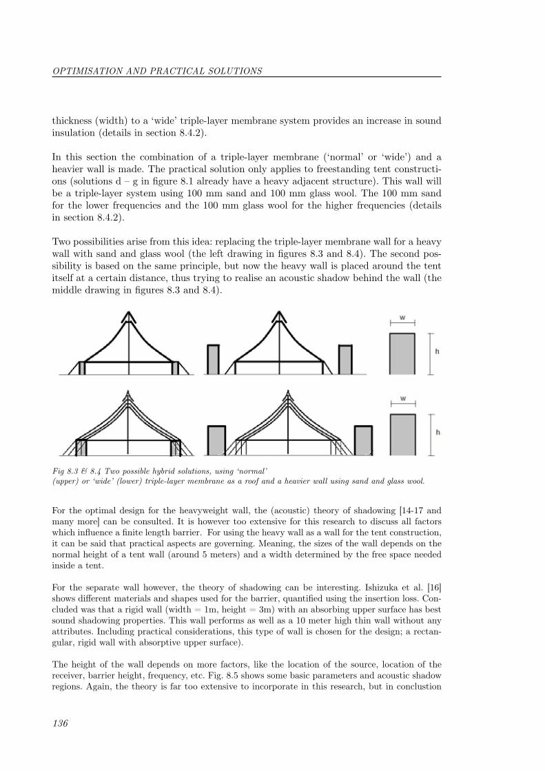
136
thickness (width) to a ‘wide’ triple-layer membrane system provides an increase in sound insulation (details in section 8.4.2).
In this section the combination of a triple-layer membrane (‘normal’ or ‘wide’) and a heavier wall is made. The practical solution only applies to freestanding tent constructi-ons (solutions d – g in figure 8.1 already have a heavy adjacent structure). This wall will be a triple-layer system using 100 mm sand and 100 mm glass wool. The 100 mm sand for the lower frequencies and the 100 mm glass wool for the higher frequencies (details in section 8.4.2).
Two possibilities arise from this idea: replacing the triple-layer membrane wall for a heavy wall with sand and glass wool (the left drawing in figures 8.3 and 8.4). The second pos-sibility is based on the same principle, but now the heavy wall is placed around the tent itself at a certain distance, thus trying to realise an acoustic shadow behind the wall (the middle drawing in figures 8.3 and 8.4).
Fig 8.3 & 8.4 Two possible hybrid solutions, using ‘normal’ (upper) or ‘wide’ (lower) triple-layer membrane as a roof and a heavier wall using sand and glass wool.
For the optimal design for the heavyweight wall, the (acoustic) theory of shadowing [14-17 and many more] can be consulted. It is however too extensive for this research to discuss all factors which influence a finite length barrier. For using the heavy wall as a wall for the tent construction, it can be said that practical aspects are governing. Meaning, the sizes of the wall depends on the normal height of a tent wall (around 5 meters) and a width determined by the free space needed inside a tent.
For the separate wall however, the theory of shadowing can be interesting. Ishizuka et al. [16] shows different materials and shapes used for the barrier, quantified using the insertion loss. Con-cluded was that a rigid wall (width = 1m, height = 3m) with an absorbing upper surface has best sound shadowing properties. This wall performs as well as a 10 meter high thin wall without any attributes. Including practical considerations, this type of wall is chosen for the design; a rectan-gular, rigid wall with absorptive upper surface).
The height of the wall depends on more factors, like the location of the source, location of the receiver, barrier height, frequency, etc. Fig. 8.5 shows some basic parameters and acoustic shadow regions. Again, the theory is far too extensive to incorporate in this research, but in conclustion
OPTIMISATION AND PRACTICAL SOLUTIONS

137
it can be that the separate wall can’t be too far from the source (read: festival tent) in order to be effective. Theory also shows [15] that the barrier is far less effective if the source is above the height of the barrier; thus, effective heavy walls should be higher than the tent itself. All in all, the option using the heavy wall as wall for the tent itself is more effective.
Fig. 8.5 Source-barrier-receiver configura-tion (a); geometrical-acoustics regions (I, II, and III) around the barrier and compo-sition of the sound field with corresponding propagation paths in each region (b); e de-notes edge, S source, R receiver, iS image source with respect to the barrier; barrier modelled as infinitely thin half plane [15]
8.2.5 Pneumatic structures
Pneumatic structures (air inflatable) can be interesting in relation to the fact that for a good sound insulation, possible sound leaks should be minimized, and these structures must be airtight. This possibility is not explored in this research however.
8.3 Active solutionsIn section 8.2 all kinds of passive solutions for improving/optimising the sound insulation were discussed. This section will shortly discuss an active solution: active noise control, also referred to as ‘noise cancelling’, ‘noise cancellation’ or ‘antinoise’. Active noise control (ANC) is achieved by introducing a cancelling antinoise wave through an appropriate array of secondary sources. These secondary sources are interconnected through an electronic system using a specific signal proces-sing algorithm for the particular cancellation scheme [18].
Active noise control (ANC) [18] involves an electro-acoustic or electromechanical system that cancels the primary (unwanted) noise based on the principle of superposition; specifically, an an-tinoise wave of equal amplitude and opposite phase is generated and combined with the primary noise, thus resulting in the cancellation of both noises. The ANC system efficiently attenuates low-frequency noise where passive methods are either ineffective or tend to be very expensive or bulky. Thus, for the main issue in this thesis this might be advantageous.
But what are the current applications and practical considerations? Applications have been te-sted through experiments by [19]. Current applications are passenger cabins in the automotive industry, air-conditioning ducts and all kinds of installation units and cabins in airplanes, ships, boats, etc. Up to now, the frequency range is quite small and thus only applicable to cancel out a certain frequency. It is furthermore highly directional, thus creating difficulties for larger spaces than e.g. the cabins mentioned above. It would be too much effort, technically too difficult, and too expensive to incorporate in the practical solutions for this thesis. Another disadvantage is that when very unpredictable sound is produced, very fast processors are needed to generate the desired antinoise.
ACTIVE SOLUTIONS

138
8.4 Assembly and details
In preceding sections some solutions have been sketched, but in this section more details are avai-lable on the assembly procedure and some details for the given solutions. Almost all membrane structures and tents build until now are single-leaf systems, where good reference can be found on details. Triple-leaf systems give far more difficult details and a different assembly procedure.
Before discussing the assembly procedure, the permanent and temporary structures should be dis-tinguished. Detailing and assembly are different for both ways. For temporary membrane structu-res (focus here: festival tents), erection speed, costs, manageability of materials and building ease are important aspects. Whereas there is less emphasis on these factores for permanent building, usually more project budget is available and detailing is done differently.
8.4.1 Assembly procedure
For the temporary tent building industry it is all about costs, speed of erection and building dif-ficulty. These three (main) aspects are looked at, regarding the ‘wide’ or ‘normal’ triple-layer sys-tem. These have been discussed in sections 8.2.1 and 8.2.3 respectively. The ‘normal’ triple-layer system has one layer of 10 mm aerogel in its first cavity and 200 mm of glass wool in its second cavity, whereas the ‘wide’ triple-layer system has per cavity an extra 1 meter air cavity. The latter can be pictured as ‘three tents over each other’.
The erection of a single layer tent structure is done by first placing the masts (lattice masts), using ropes and manpower. These ropes will keep them in place and stay there in case the membrane fails during use. The packages of membrane are brought in and placed between different mastss, using a forklift. Normally rectangles of 15 by 30 meters of membrane (figure 8.6) are delivered separately (the cutting patterns are already welded during production making these bigger pieces).
Fig. 8.6 Top view of six masts and one piece of membrane of 15 x 30 meter
These pieces weigh around 1 kg/m2 *15*30 is 450 kg. A ring is then placed around each mast (two separate parts, not over the mast) and attached to the membrane piece. This is then, again by pure manpower usually, lifted, using a rope attached at the top of the mast on a pulley. After fixing these ropes the edges of the tent structure are placed on the smaller (around 5 meters) side ‘columns’ (steel lattice poles) and tensioned by straps.
The masts can be placed in one day (depending on the size of the tent), but the membrane placement requires more work. The idea for the ‘wide’ triple-leaf systems was to erect three dif-ferent tents over each other. To begin with, this is three times more work than a single layer tent (excluding the surely more difficult erection of the second and third tent). Since erection time is essential, this idea is not practically feasible. On top of that, erecting three tents takes longer, so this is more expensive as well. This is not a problem for the ‘normal’ triple-leaf system as later on will be elaborated.
OPTIMISATION AND PRACTICAL SOLUTIONS

139
Another issue is illustrated in figure 8.7. The ‘wide’ system (right in the figure) uses three main membranes, but needs an extra two to hold the glass wool and aerogel in place, resulting in five membranes for this type of construction. Again, this is a disadvantage in terms of costs.
Fig. 8.7 The amount of membranes needed for the ‘normal’ (left)
and ‘wide’ (right) triple-layer system.
A couple of reasons were mentioned above for not using the ‘wide’ triple-leaf membrane system in practice. Off course, if the benefits were a lot higher than for the ‘normal’ system, it could be reconsidered. Since the sound insulation improvement is not significantly, this advantage does not outweigh the disadvantages.
The ‘normal’ triple-layer membrane system, therefore, is better, and is discussed here in terms of assembly procedure. As with the normal single-leaf procedure, the masts are erected first. Since the outer membranes are only 250 mm apart, it is easier to handle as one single package. The entire triple-layer membrane package including glass wool and aerogel are assembled in the factory (detail 1 in section 8.4.2). They are then delivered to the construction site in pieces again. Since these pieces are a lot heavier now, the size must be reduced to 10 by 20 meters, which gives a total weight of 7.2 kg/m2 *10*20 is around 1500 kg. It is still possible to lift this with a forklift truck, usually present for normal tent construction.
Decreasing the sizes of each membrane piece has results in more closely spaced masts which is not desirable. This can be overcome by using a three point portal construction as shown in figure 8.8.
Fig. 8.8 A three point portal construction to gain more free space inside the tent and less curvature in the membrane
An advantage using this type is the reduction in curvature needed in the membrane to gain the right amount of tensile force. Less curvature is better for the filling material. In time, the material may settle a little and this effect is reduced by less curvature. Of course, double mast systems are still possible as well, when no more than 10 meters of free space is required.
To get back to the assembly procedure; like normally, rings are placed around the masts and the triple-layer membrane package is attached to it. The trick now is to only tension the outer mem-brane. The rest of the package (two layers of membrane, glass wool and aerogel) will hang under-neath (details 1-3 in section 8.4.2). Since 7.2 kg/m2 is around 0.072 kN/m2 for the outer membrane to hold and wind load is in the order of 0.5-0.7 kN/m2, it is realistic to say that it is possible to hang the package onto the outer, tensioned membrane. See section 8.4.2 to see how the package is attached to the top of the mast and the side wall.
Everything above applies only to temporary (tent) building. For permanent building there are
ASSEMBLY PROCEDURE

140
more possibilities, because usually the project budget is higher, but it is important that in all cases, enough space should be reserved for tensioning the membrane. For the rest, detailing is only limited by the designer’s imagination. To reduce sound leaks however, for all types of triple-layer membrane structures, all edges should be rigid and covered (if they’re open) with pieces of (heavier) membrane. Details can be found in section 8.4.2.
8.4.2 Details
All preceding sections gave rise to a variety of solutions for a triple-leaf system in practice. Now, based on the assembly procedure discussed in section 8.4.1, details are given for a ‘normal’ triple-leaf package (which can be either a combination of aerogel and glass wool or a variant like Glass-C). The emphasis will be on freestanding tent construction for temporary goals, but some details (detail 4) are usable for permanent membrane construction as well. As discussed in the preceding section, the ‘wide’ triple-layer membrane system is not feasible and no further details are given. The important relation between sound insulation and membrane (tent) construction is the usually present aspect of sound leaks; therefore, this will be discussed shortly.
Sound leaksDetails are very important in order to create a totally sound leak free design. This can be difficult for regular construction with steel and concrete, but for membrane building this is even worse. Membrane structures are based on an entirely tensile character, therefore resulting in the fact that cables and membranes have to be tensioned in practice. This results in a flexible design with a lot of space available for the membrane connections to rigid elements or cables.
Since sound leaks should be avoided, rigid edge connections are used throughout all detailing and solutions. Where space is needed for tensioning, usually (unavoidable) a gap arises, which will have to be covered with a piece of membrane (detail 4). This is not a very big problem for permanent construction, but quite labour intensive for temporary building. Other solutions are detailed for temporary building: a precast concrete slab for the connection from membrane to the ground with continuous filling material from top to ground (detail 3) and an inflated membrane ring to cover the hole between the top of the membrane and the cap which all (festival) tent constructions get (detail 2).
DetailingFor all solutions in figure 8.1 with a ‘normal’ triple-layer membrane system (section 8.2.1), four details are important and are repeated throughout all solutions (figure 8.9): the membrane itself,
Fig. 8.9 Four details for a ‘normal’ triple-leaf membrane structure. 1) membrane itself (including seams), 2) connection between membrane and the supporting mast, 3) connection between membrane roof and membrane wall, 4) connection between membrane and a supporting (neighbouring) structure.
OPTIMISATION AND PRACTICAL SOLUTIONS

141
10 mm aerogel
200 mm glass wool
Membrane layer
In-place holder for the filling material. Made of membrane material itself
Detail 1‘Normal’ triple-leaf membrane
system using glass wool and aerogel
the connection between membrane and the supporting mast, the connection between membrane roof and membrane wall, and the connection between membrane and a supporting (neighbouring) structure. These four details for a ‘normal’ triple-leaf membrane system/package and an explana-tion are presented now.
The pieces of membrane (10 x 20 meter) are connected to each other by a laced system where rope is pulled connected to one piece is pulled through the holes in the other piece. This laced seam/connection is then covered with a membrane flap. The seams between the cutting patterns are normal welded seams, which are identical to single-leaf membrane building.
Detail 2The top of the high point; the connection between the membrane roof and the mast
Lattice, steel mast
The rigid ring is first pulled to the top and then connected to the mast
The cap is made from triple-leaf membrane as well and placed after finishing the membrane roof
The membranes are connected by a laced system and is done on the ground
An inflated ring for acoustic sealing
The triple-leaf membrane of the roof
DETAILS

142
Detail 3b,c
Detail 3a
Detail 3a The filling material is continuous and thus not interrupted
Detail 3c The membrane is welded around a steel cable. This cable is then clamped between two steel parts and connected by a bolt
Detail 3b The precast concrete slab is put on place around the perimeter of the tent constructuin surface. The membranes coming down from the outer, tensioned membrane are atta-ched to the concrete foot
Detail 3 Connection between the membrane roof and the ground
Cable
Loadbearing poal
Anchor
The triple-leaf membrane
The tensioned outer membrane continues to the structural connection and another membrane is connected to the outer one the hold the filling material in place for the vertical part
Detail 3c
Single membrane
Sealing strips agains acoustic leaks
Concrete slab
Detail 4 Rigid connection to another (building) element
The triple-leaf membrane
The outer membrane is tensioned by a separate edge cable
The edge connection of the tensioned membrane is open and thus needs to be sealed with another mem-brane (usualy heavy)
The package is connection to the outer membranelike in detail 3.
The edge of the package is fabrication sealed
The connecting piece of membrane (connected on the outer membrane) is fixed on a (building) element
OPTIMISATION AND PRACTICAL SOLUTIONS

143
The hybrid solutions from section 8.2.4 give rise to two more details (figure 8.10): the heavy wall itself (detail 6) and the connection between the heavy wall and the membrane roof (detail 5). For practical reasons, concrete, stackable blocks are used (figure 8.11).
Fig. 8.10 Three details for a hybrid solution. 8) the heavy wall, 9) connection between membrane and heavy wall, 10) connection between ‘wide’ membrane and heavy wall.
Detail 5 Connection between the roof membrane to the heavy wall system
Detail similar to detail 3a
Detail similar to detail 3b, but now on a heavier wall
Concrete, stackable blocks
Fig 8.11 Concrete, stackable blocks from Betonblock.eu [20]
DETAILS

144
OPTIMISATION AND PRACTICAL SOLUTIONS
8.5 Other aspectsIn this research the main (and only) focus is on acoustics (especially on sound insulation aspects). Of course, many more aspects are of importance in practice. Building physics aspects, but other aspects like soiling and durability (recycling) as well. Most of them are summed up here.
8.5.1 Building physics aspects
Some aspects relevant for membrane building in general are [2]:
• Rain noise• Thermals aspects o Thermal insulation capacity o Solar transmission, absorption and reflection o Specific heat capacity (Integration with phase change materials) o Heat radiation behaviour o Selectivity of transmission o Thermal expansion• Lighting aspects o Transmission, absorption and reflection in the range of visible light o Colour fidelity of reflection and transmission o Refractive behaviour o Light scattering• Moisture aspects o Precipitation and water vapour tightness o Moisture absorption capacity o Resistance to water and chemicals• Fire protection aspects o Detailed reaction to fire: flaming droplets, hole formation for smoke escape o Toxicity of fumes in a fire o Speed of fire development
Some of these aspects can be elaborated in relation to a triple-leaf membrane system in comparison to a single-leaf membrane. To start with, the thermal insulation capacity has increased enormously (aerogel is beneficial here as well) and therefore needs less heating. On the other hand, during summer (most festivals are in the summer) a single-leaf mem-brane tent can get quite hot inside and that increases as well (solar radiation is better retained however). Maybe a cooling system is needed and probably good ventilation.
The entire membrane package is less (read: not) translucent than a single-leaf membrane, but ETFE-foil is applied where translucency is not the objective.
In a single-leaf membrane structure, normally no water vapour layer is applied, but when using a triple-leaf membrane package, a vapour layer should be added (in the package) to prevent moisture to get to the filling material (depends on the membrane material used as well), especially for permanent construction. The package is still as water resistant as

145
a single-leaf membrane.
For composite materials (e.g. ETFE-coated glass fibre fabric) containing multiple basic materials, the ratio of the combustible to the incombustible mass components is crucial for fire protection. In this example, the fire characteristics depend highly on the fibres/coating ratio. For application of glass wool and aerogel, combined with membrane, more research should be carried out.
8.5.2 Other membrane construction related aspects
Some other aspects (other than building physics) are listed below in relation to mem-brane building [2]:
• Ecological/ Energy aspects o Consumption of resources in production o Density o Potential period of usage (durability) o Energy consumption during production o Toxicity o Electromagnetic shielding• Loading and durability aspects o Mechanical load-carrying capacity o Chemical resistance o Service temperature range o Resistance to UV radiation• Other aspects o Building costs o Erection time o Production process (its ease) o Soiling o Electrical conductivity o Self-illumination (electroluminescence) o Thermochromism
From an ecological point of viw, a triple-leaf membrane package has a higher consump-tion of resources than single-leaf membranes, but has a higher potential for a longer period of usage (especially for permanent buildings), although much still depends on the membrane fabric itself.
Loading and durability aspects are not different from single-leaf membranes. Recycling of membrane structures is quite hard when using reinforced membrane, since these in-dividual materials should be separated. The Texyloop® process is specially designed for membrane materials. [21]
Most other aspects have already been discussed in preceding sections (or chapters), but in relation to the building costs itcan be said that aerogel is (still) 20 $/m2, which is 10 times more than conventional mineral wool. Using this high-tech material thus requires
OTHER MEMBRANE CONSTRUCTION RELATED ASPECTS

146
a much higher project budget.
References1. De Boer Structures: http://www.deboer.com/2. Knippers et al. (2011), Construction manual for polymers + membranes, Birkhäuser (Basel), Edition Detail (Munich), ISBN: (soft cover) 978-3-0346-0726-13. Koch, K.-M. (2004), Membrane structures, Published by Prestel Verlag4. Bies, D.A. (1988), Acoustical properties of porous materials, In Beranek, L.L (ed.), Noise and Vibration control, Washington, DC. Institute for Noise Control Engineering, 245-269. ISBN: 09622072095. Nichols, R.H. (1947), Flow-resistance characteristics of fibrous acoustical materials, Journal of the Acoustical Society of America, Vol. 19 (5), 866-8716. Hopkins, K. (2007), Sound insulation, First Edition, published by Elsevier Science Publishers Ltd.7. Mechel, F.P. (2008), G - Porous Absorbers in Formulas for Acoustics, Springer International Publisher8. Verseidag, Coating and Composite,<http://www.verseidag.de/>9. General information about ‘lead’,< http://en.wikipedia.org/wiki/Lead>10. Information about ‘modified bitumen’, <www.roofhelp.com/choices/modified/>11. Fuentes-Auden, C. (2008), Evaluation of thermal and mechanical properties of recycled polyethylene modified bitumen, Polymer Testing, Vol. 27, 1005–101212. Information about ‘HDPE’, <http://www.makeitfrom.com/data/?material=HDPE&typ e=Mechanical>13. Information about ‘HDPE’, <http://www.substech.com/dokuwiki/doku. php?id=thermoplastic_high_density_polyethylene_hdpe>14. Menounou et al. (2010), Shadowing of directional noise sources by finite noise barriers, Applied Acoustics, Vol. 71, 351-36715. Menounou et al. (2000), Directive line source model: A new model for sound diffraction, J. Acoust. Soc. Am., Vol. 1-7, No. 616. Ishizuka, T. and Fujiwara, K. (2004), Performance of noise barriers with various edge shapes and acoustical conditions, Applied Acoustics, Vol. 65, 125-14117. Pirinchieva (1991), The influence of barrier size on its sound diffraction, Journal of sound and vibration, Vol. 148, Issue 2, 183-19218. Kuo, S.M. and Morgan, D.R. (1999), Active Noise Control: A tutorial review, Proceedings of the IEEE, Vol. 87, No. 619. Kuo, S.M. and Morgan, D.R. (1996), Active Noise Control Systems – Algorithms and DSP Implementations, New York: Wiley, 199620. Betonblock, stapelbare betonblokken en mallen, <www.betonblock.eu>21. Texyloop, textile recycling, http://www.texyloop.com/#/85/
OPTIMISATION AND PRACTICAL SOLUTIONS


149
In the first part of this master thesis research has been done into the present knowledge of membrane structures, acoustics and, more importantly, their common grounds. The fo-cus here is on airborne sound insulation only, but some knowledge about absorption was necessary. A state-of-the-art review has been made where single-leaf, double-leaf and the basis for triple-leaf membrane structures in relation to sound insulation (and absorption) are discussed. Some important conclusions from this literature research were adopted as a basis for the present membrane package and results.
From the research on single-leaf membrane systems, it was concluded that the tension in the membrane was negligible in relation to sound insulation. For very high tensile forces the sound insulation did decrease a little; however, at these tensile forces the membrane material would rip because of the lesser membrane’s tearingcapacity. From experimental studies and mathematical models on mainly double-leaf membrane structures it can be concluded that a system with a filled cavity has higher sound insulation (which is ob-vious) than an empty system; that filled double-leaf membrane systems perform better than empty triple-layer membrane systems, and that filled triple-layer membrane systems (in theory, no experiments have been carried since out in this respect) perform better than filled double-leaf membrane systems. The flow resistance of the membrane has a high influence on the sound insulation of membrane systems.
In the second part, the above mentioned conclusions were adopted in order to design a base system, upon which a number of variants were composed. Based on available mem-brane materials, four membrane configurations were used, with a permeable leaf on sound incidence side and two variants with three impermeable membranes. The first category is based on a lower flow resistance of the material, resulting in more airflow through the material, creating a better absorptive surface, and better room acoustics. The latter, however, being entirely impermeable, is creating a better sound insulating system. Two filling materials (glass and polyester wool) were chosen, based on especially low weight and good absorption characteristics; the third material (aerogel) was chosen because of the high potential of the material (up to now mainly for thermal insulation). The cavity thickness was, using the Multiple Layer Model and the restriction of 7 kg/m2 for the en-tire membrane system, determined to be 250 mm for the conventional materials and 30 mm for the aerogel variants.
The different variants have been measured in the Peutz’ Laboratory for Acoustics; the triple-layer filled membrane systems as well as three impermeable single-leaf membranes were measured, in order to get more insight into the behaviour of membrane in relation to sound insulation. It can be concluded that for the single-leaf membrane materials the results are closest to the normal mass law for random incidence. For a perfect fit, the sound insulation according to the mass law should be 3 dB increased to create an empi-rical model valid for single-leaf membrane materials.
From the results of the triple-leaf membrane system, the research concentrated on sound
Conclusions and recommendations 9

150
insulation only, since the variants with three impermeable membranes performed signi-ficantly better than the variants with a permeable leaf on sound incidence side. These variants may perform worse from a room acoustical point of view. The measurement results for the triple-leaf systems were compared to the computer model Multiple Layer model, the mathematical models of Sakagami for triple-leaves and conventional triple-leaf formula by Vinokur. The MLM was the only model which could incorporate filling material; therefore, this model described the results best.
From the measurements it can be concluded that overall all glass wool variants perform better in relation to sound insulation than the aerogel or polyester wool. Better than polyester wool, because of the different characteristics of the material (mainly flow resis-tance), and better than aerogel presumably due to the considerable greater thickness of the cavity. In more detail it can be said that aerogel performs a little better at the very low frequency range (200 Hz or lower), which is the main issue for lightweight building in general. Since the measurement results are less reliable at these low frequencies this conclusion is based on the MLM model only. The MLM still has to be verified at the lower frequency range by measurements.
In the third and final part, some of the parameters of the system were refined and opti-mised. Optimising the filling material, the membrane itself and the cavity thickness were discussed. The filling material can be optimised (mainly) by using a higher flow resistive material, but this is not an option when restricting to 7 kg/m2. The result here is a com-bination of a single aerogel mat for the low frequencies and a layer of glass wool for the higher frequencies (should be verified by low frequency measurements). Changing the membrane material itself amounts always to a higher surface density, which is not an op-tion in this research. Using a (much) wider cavity gives (a little) higher sound insulation values and is optimised when the cavities are (on top of the 10 mm aerogel and 200 mm glass wool) 1 meter each.
The system with the very wide cavities is abandoned due to practical reasons (for tem-porary tent constructions): three tents over each other have to be made, which is more difficult, more costly and reduces the speed of erection enormously. The system with 10 mm aerogel and 200 mm glass wool can be put into effect by making it into one package, which then is installed on site like a single-leaf tent structure. Detailing however is weigh-tier, since no sound leaks may occur, but referring to details it can be positively said that it is practically feasible to realize. Noted should be that the Glass-C variant is not much worse than the combination configuration described above and can be detailed likewise.
Recommendations
For more profound conclusions more aspects should be considered than could be done in this MSc-research. This is mainly due to the lack of time which is available for a master thesis, but some due to the assumptions done and the definition of the research’ objecti-ves. Some recommendations are discussed below for further research on the subject and categorized according to the three parts mentioned in the conclusions:
In this research only direct airborne sound transmission is taken into account. Off course,
CONCLUSIONS AND RECOMMENDATIONS

151
in practice, rain noise, structure-borne and impact sound transmission is important as well. Research has to be carried out into the vibration effects of sound waves through a membrane and the impact sound insulation for mainly rain noise.
The theoretical models used here were two mathematical models (Sakagami and double-cavity theory) and one computer model (MLM). For especially membrane structures a computer model was produced during an EU-funded research project called contex-T. That model gives good results on measurements done on double-leaf systems, but was not available. The two mathematical models were not (yet) designed to incorporate any filling material which is off course important for any good comparison to measurement results. It is recommended to expand these models so that filling material can be modelled.
Results (MLM) show rather good sound insulation values for aerogel at low frequencies and since this is the main issue for lightweight building in general, more research can be done here. Recommended is to especially look at subwoofer frequencies (20-100 Hz). This low frequency research can also be expanded by searching for heavyweight materials with a very high capacity to absorb the sound energy. The model should be verified by measurements for the lower frequency range though.
To optimise the filling material for membrane structures the flow resistance is important. Usually, with higher flow resistance higher, unwanted surface density follows from this. But flow resistance is not the only parameter in the effect of absorption materials; the pore structure is of importance as well and more research can be done in optimising the pore structure in relation to a certain maximum weight.
Research has shown that the tension is negligible for sound insulation outcomes, but only measurements were performed (like in this research) on very small surfaces (in the range of 2 m2). The effect of tension as well as all other effects is recommended to be tested using a real membrane structure made with triple-layer membrane. The finished, flexible structure (crimping and expanding) might react differently in relation to sound insula-tion. Other building physic aspects should be extensively studied here as well since tent structures tend to get very hot in summer, especially for triple-leaf structures.
Another practical problem is the bonding between the filling material and membrane. How this can be done best needs to be explored more. Ideas are a fibre connection with a round plastic plate through the filling material (used here as well as in normal building), a more direct fibre connection between both materials and some kinds of glue.
RECOMMENDATIONS
