trihal - more energy · type and range trihal is a three-phase dry-type transformer cast under...
TRANSCRIPT

schneider-electriccom
2016 Catalog
Trihal Cast resin transformer
Distribution Transformers
Contents
Presentation 4
Technology 10
Options and accessories 16
Tests and technical information 26
Internet 34
schneider-electriccom | 3Trihal Catalog
schneider-electriccom4 | Trihal Catalog
Presentation
schneider-electriccom | 5Trihal Catalog
Presentation
Introduction 6
Basic equipment 7
Technology and construction 7
Type and range 7
Environmental protection 7
Technology and construction 8
Standards and configurations 8
Presentation
schneider-electriccom6 | Trihal Catalog
Setting a new standard for dry-type cast resin transformers
For a high level of safety and exceptional environmental friendliness therersquos nothing
to beat a dry-type cast resin transformer
The epoxy resin insulation used in this kind of transformer means no oil is used
greatly reducing the risk of fire and improving recyclability all without loss of
performance compared to other transformer types Dry-type cast resin transformers
are therefore ideal for critical applications and high-traffic areas
Even among dry-type cast resin transformers Trihal from Schneider Electric stands
out due to its outstanding performance and unrivalled certifications
Trihal is a best-in-class range of dry-type cast resin transformers rated from 160
kVA up to 15 MVA with insulation rated up to 36 kV Itrsquos perfectly suited to a wide
variety of industries from densely-populated buildings and critical infrastructure to
heavy industry and renewable energy production
Crucially Trihalrsquos safety and performance certifications are without equal and the
range is compliant with IEC60076-11 and IEC60076-16 as well as ISO 9001 ISO
14001 and ISO 18001
All this results in optimum efficiency with very little maintenance for a long service
life
Trihal with enclosure
Introduction
Introduction
Mining metalamp minerals
Wind
AirportsData centers
Oil and gas
Hospitals
Automotive
Food andbeverage
Buildings
Nuclear
PM
1059
11
Presentation
schneider-electriccom | 7Trihal Catalog
Assembly line
Technology and construction
Trihal benefits from two key processes
bull a linear voltage gradient from top to bottom of the HV coil generally used
bull a fireproof casting system
This technology developed by Schneider Electric has wide variety of applications
and meets different customer requirements
Type and range
Trihal is a three-phase dry-type transformer cast under vacuum in epoxy resin with
an active filler
This active filler composed of alumina trihydrate is the origin of the Trihal
trademark
Trihal transformers are supplied with or without an enclosure and from 160 kVA to
15 MVA and up to 36 kV
Environmental protection
The Trihal competence center was the first French facility to be certified ISO 14001
in this sector and has been since 1998
Trihal is designed and manufactured to be environmentally-friendly providing an
ecological solution for HVLV transformers
Environmental protection is integrated in our management systems in order to
promote the protection of all natural resources and continuously improve conditions
for a clean environment
The product design focuses on minimizing its environmental impact
Magnetic core
Basic equipmentP
M10
5912
PM
1059
13
Presentation
schneider-electriccom8 | Trihal Catalog
Standard design Possible adaptation
Manufacturing standards IEC 60076-11 EN 50588 EN 50629 GOST-R BS IEEE
Class tests C3 E3 F1 le 5 pC
HVLV coils HV encapsulated in cast resinLV impregnated HV and LV encapsulated in cast resin
Installations Indoor use
bull IP00 (without enclosure)IP31 (with enclosure)
bull C2 Corrosivity class Medium durability (in compliance with ISO 12944-6)
Outdoor use with properly designed enclosure
bull From IP35 up to IP44 (with enclosure)
bull Up to C5-Marine Medium durability (in compliance with ISO 12944-6)
Winding material According to manufacturer optimization (Cu) CuCu
Phases Three-phase Single-phase
Cooling system Standardbull AN (natural air)
Optionbull AF (air forced)
bull 40 performance reserves
AFWF (air forced water forced)
Maximum TdegCaltitude 40degC at any time1000 m Up to 65degCAbove 1000 m
Thermal class insulation According to IEC 60085 Class F
Temperature rise 100 K 80 K (for 40degC) Temperature rise adapted to maximum TdegC
Rated frequency 50 Hz or 60 Hz
Rated power Up to 3150 kVA Up to 15 MVA
Impedance voltage Uk From 4 to 6 bull Lower than 4
bull Higher than 6 - Up to 11
Vector groups Dyn YNd All others according to IEC
Rated HV insulation Up to 36 kV (IEC) Up to 405 kV (GOST-R)
HV tapping Off-circuit tapping links 3 or 5 positions +- 25 Off-circuit tapping links up to 9 positions +- 25 or higher
HV terminals Standard HV connections HVMV plug-in or porcelain bushings through dedicated cable boxes (IEC BS or NEMA compliant)
Rated LV (MV) insulation 11 kV Up to 72 kV
LV terminals bull Standard LV connections
bull Top or bottom entry (on request)
bull LV cable ducting interface (Canalis)
bull Side entry through dedicated cable boxes (IEC BS or NEMA compliant)
Thermal protection bull AN cooling system 6 PTC sensors (or 3 PT100) + Thermal Relay
bull AF cooling system 9 PTC sensors (or 6 PT100) + Thermal Relay
Standards and configurations
Technology and construction
Presentation
schneider-electriccom | 9Trihal Catalog
Standard design Possible adaptation
Accessories bull Standard 4 bi-directional flat rollers 4 lifting holes 4 carriage holes on the sub-base 2 earthing points rating plate
bull Most common options Anti-vibration pads remote communication for thermal relay marshalling box earthing ball surge arresters
Locking device for plug-in bushings current transformers automatic voltage regulator panel On Load Tap Changer special paint color for enclosure
Test certificate Routine tests in accordance with IEC 60076-11 bull Type tests in accordance with IEC 60076-11 temperature rise test lightning impulse test
bull Special tests in accordance with IEC 60076-11 noise level measurement short-circuit test
bull Others seismic test resistance climatic environmental or fire class tests
Standards and configurations
Technology and construction
schneider-electriccom10 | Trihal Catalog
Technology
schneider-electriccom | 11Trihal Catalog
Technology
Manufacturing process 12
Magnetic core 12
LV winding 12
HV winding 13
HV casting system 13
HV coil casting process 14
HV support wedges 14
schneider-electriccom12 | Trihal Catalog
Technology
Magnetic core
The magnetic core is made from laminated grain-oriented silicon steel
The choice and grade of steel and the cutting pattern and method of assembly
minimize the loss level and the no-load current resulting in a very low noise level
Once assembled it is protected against corrosion
LV winding
The LV winding is made of either aluminium or copper foil to eliminate axial stress
under short-circuit conditions the foil is insulated by a Class F inter-layer film pre-
impregnated with heat-activated epoxy resin
The ends of the windings are protected and insulated using end packing made of
Class F materials
The whole winding is polymerized by being placed in an autoclave for 2 hours at
130degC which guarantees
bull outstanding resistance to harsh industrial atmospheres
bull excellent dielectric withstand
bull very good resistance to radial stress under short-circuit conditions
Each LV winding ends in a tin-plated aluminum or copper connection point
enabling connections to be made without using a contact interface
Magnetic core being assembled
LV winding with foil technology
Manufacturing process
Control of the industrial process very low partial discharge rate (le 5 pC)
PM
1059
14P
M10
5915
Technology
schneider-electriccom | 13Trihal Catalog
HV winding
The HV winding is usually wound from insulated aluminum or copper wire using a
method developed and patented by Schneider Electric ldquoa linear voltage gradient
from top to bottomrdquo
For higher currents the MV winding can be wound using ldquostriprdquo technology
These methods are used to obtain very low stress levels between adjacent
conductors
This winding is casted and molded under vacuum using Class F filling and
fireproofed resin the Trihal casting system
These processes give coils very high dielectric properties with very low partial
discharge level (guaranteed le5 Pc)(1) which is a decisive factor in influencing the
transformerrsquos life span and its lightning impulse withstand(2)
HV tapping points on the copper connection bars enable connections to be made
without using a contact interface (grease bi-metallic strip)
HV casting system
The system provides a vacuum-cast coating of fire-resistant filled resin a
technology developed and patented by Schneider Electric
The Class F casting system comprises
bull A bisphenol-based epoxy resin with sufficient viscosity to ensure excellent impregnation of the windings
bull An anhydride hardener ensures very good thermal and mechanical properties A flexibilizing additive gives the casting system the necessary elasticity to prevent cracking during operation
bull An active powdered filler consisting of silica and especially of alumina trihydrate thoroughly mixed with the resin and the hardener
bull Silica which reinforces the castingrsquos mechanical strength and improves heat dissipation
The alumina trihydrate guarantees the Trihal transformerrsquos intrinsic fire performance
Alumina trihydrate produces 3 fire-retardant effects which occur in the event of
calcination of the casting system (when the transformer is exposed to flames)
bull 1st fire-retardant effect refracting shield of alumina
bull 2nd fire-retardant effect barrier of water vapor
bull 3rd fire-retardant effect temperature held below the fire point
The result of all 3 fire-retardant effects is immediate self-extinguishing of the Trihal
transformer
In addition to its dielectric qualities the casting system gives the Trihal transformer
excellent self-extinguishing fire resistance and excellent environmental protection
against harsh industrial atmospheres
(1) Validated in external laboratory
(2) It is important to note that the level of partial discharge remains the same throughout the
transformerrsquos service life
HV winding with strip technology
Manufacturing processP
M10
5916
HV casting process
PM
1059
17
schneider-electriccom14 | Trihal Catalog
Technology
HV coil casting process
The process from proportioning the resin through to polymerization is fully
controlled by microprocessor preventing any inopportune manual operation
The alumina trihydrate and the silica are vacuum-dried and degassed to eliminate
all traces of humidity and air which could degrade the casting systemrsquos dielectric
characteristics
Half is mixed with the resin and half with the hardener under hard vacuum and at a
controlled temperature to give two homogenous pre-mixes
Another thin film degassing precedes the final mixing Vacuum casting is then
carried out in dried and pre-heated molds at an optimal impregnation temperature
The polymerization cycle begins with gelification at 80degC and ends with long
polymerization at 140degC
These temperatures are close to those of a transformer in service enabling
mechanical stresses to be eliminated which could lead to the coating cracking
HV coil support wedges
The high voltage winding is centered on the magnetic core and held in place
vertically by an efficient wedging system Thanks to the unique design of these
wedges they can be assembled in a variety of ways to suit different levels of HV
insulation
The wedges are designed according to customersrsquo needs to cope with different
environmental and mechanical conditions (seismic withstand vibration etc)
HV coil support wedges
Manufacturing processP
M10
5918
Notes
schneider-electriccom | 15Trihal Catalog
schneider-electriccom16 | Trihal Catalog
Options and accessories
schneider-electriccom | 17Trihal Catalog
Options and accessories
Options 18
Trihal CastCast 18
Trihal LVLV up to 400 kVA - 11 kV 18
Thermal Protection 19
T thermal protection using PT100 sensors 19
Z thermal protection using PTC sensors 20
Forced Ventilation 21
Connections 22
Low voltage connections 22
High voltage connections 22
High voltage surge arresters 23
Vibration damping 23
Protective Enclosure 24
IP protection indices 24
IK protection indices 24
Options and accessories
schneider-electriccom18 | Trihal Catalog
Options
Trihal Cast Cast
Trihal Cast Cast Cast Resin transformers provide high reliability and long durability
with both MV and LV windings casted under vacuum It is a perfect solution for
harsh environmental conditions such as high pollution or humidity It also provides
enhanced mechanical and thermal features
Application fields
bull OampG MMM
bull Utilities Power plants Water Nuclear
bull Infrastructure Public and commercial buildings such as Airports Hospitals etc
bull Small Industries Textile Automotive Pharmaceutics Food etc
Trihal LVLV up to 400 kVA - 11 kV
Trihal LVLV Cast Resin transformers provide reliability and longevity in harsh
environmental conditions such as high pollution or humidity It adapts to significant
temperature and charge variation constraints
Description
Trihal LVLV is suitable for
bull Earthing transformer
bull Change of earthing system
bull Isolate network disturbances
bull Change of network voltage
bull Galvanic isolation
bull Energy conversion
bull Dimmer monitoring
bull High power transformer pre-magnetization
Application fields
bull Buildings
bull Industry
bull Oil amp Gas
bull Marine
bull Secure Networks
Trihal CastCast benefits
bull Guaranteed against fire hazards (self-extinguishing)
bull Totally insensitive to harsh environments (pollution or condensation)
bull Easy and quick to install with a minimum maintenance
bull Enhances the mechanical stability and shock withstandability during the thermal overloads
bull Adapts itself to significant temperature and load changes
Trihal LVLV benefits
bull Guaranteed against fire hazards (self-extinguishing)
bull Totally insensitive to harsh environments (pollution or condensation)
bull Easy and quick to install with a minimum maintenance
Trihal LVLV
PM
1054
34
Options and accessories
schneider-electriccom | 19Trihal Catalog
The Trihal cast resin transformer can be protected by monitoring the winding
temperature
This monitoring is done by
bull PT100 sensors + associated relay for alarm and trip and real-time temperature
monitoring
bull PTC sensors + associated relay for alarm and trip
T thermal protection using PT100 sensors
This thermal protection device gives a digital display of the winding temperatures
and includes
bull PT100 sensors
- The main feature of a PT100 sensor is that it gives the real-time
temperature on a scale of 0degC to 200degC see graph opposite
(accuracy 05 of the measurement scale 1 degree)
- Temperature control and display functions are performed via a digital
thermometer The 3 sensors each comprising 1 white wire and 2 red wires
are installed in the live part of the Trihal transformer with 1 located on each
phase
- They are placed in a tube allowing them to be replaced if necessary
bull 1 terminal block for connecting the PT100 sensors to the T digital
thermometer
- The terminal block is equipped with a plug-in connector PT100 sensors are
supplied connected to the terminal block fixed to the top of the transformer
bull 1 T digital thermometer characterized by 3 independent circuits
- 2 of the circuits monitor the temperature captured by the PT100 sensors
one for alarm 1 the other for alarm 2
When the temperature reaches 140degC (or 150degC) the alarm 1 information
(or alarm 2tripping) is processed by 2 independent output relays
equipped with changeover contacts
The position of these relays is indicated by 2 diodes (LEDs)
- The third circuit monitors sensor or electrical supply failure
The corresponding relay (FAULT) which is independent and equipped
with changeover contacts is instantly switched as soon as the device is
supplied with power Its position is also indicated by a diode (LED)
The purpose of a FAN output is to control starting of tangential fans in the event of
forced ventilation of the transformer (AF) this option is shown on page 21
An additional input (CH4) can be connected to a sensor outside the transformer (not
supplied) intended to measure the ambient temperature in the HVLV substation
A digital output (RS 232 or 485) or a 4-20 mA analog output is available for
connection to a PLC or computer
A FAN 2 output is available as an option to control starting of an additional fan
The T digital thermometer is delivered with an installation manual
Resistance
Temperature
Typical graph of a PT100 sensor
Thermal protection
Please note since the transformer is thermal Class F the user has responsibility for setting the T digital thermometer with a maximum temperature of 140degC for alarm 1 and 150degC for alarm 2 (tripping)Failure to comply with these maximum temperatures absolves Schneider Electric of any liability for damage that could possibly be incurred by the transformer
DM
1052
00D
M10
5201
Schematic diagram for the T digital thermometer
terminal block mounted on the transformertransformer columns
PT100 outPT100 sensors fitted in the transformerPT100 in
FAN 2 ventilation outside the transformer
alarm 1 140degCalarm 2 150degCmonitoring of sensor failurestransformer ventilation (AF) 130degC
PT100 sensors outside the transformer
TBTC
TBTC
PT100 outPT100 in
RS 232 orRS 485 seriesoutput
FAN 2
AC - DC
24-220 V supply
AL 1
AL 1AL 2FAULTFAN
AL 2 FAULT FAN
Options and accessories
schneider-electriccom20 | Trihal Catalog
Terminal block for connecting sensors to the electronic converter
threshold
Resistance
Temperature
Typical graph of a PTC sensor
Thermal protectionD
M10
5202 Z thermal protection using PTC sensors
The standard version for naturally cooled (AN) transformers comprises
bull 2 PTC sensor sets positive temperature coefficient thermistors mounted
in series the first set for alarm 1 the second set for alarm 2
The PTC sensor resistance increases very steeply at a rated and factory-set
threshold temperature which is not adjustable (see graph opposite) This abrupt
increase is detected by a Z electronic converter
These sensors are installed in the live part of the Trihal transformer with one
alarm 1 sensor and one alarm 2 sensor on each phase They are placed in a
tube allowing them to be replaced as necessary
bull 1 terminal block for connecting the PTC sensors to the Z electronic
converter The terminal is equipped with a plug-in connector The PTC sensors
are supplied connected to the terminal attached to the top of the transformer
bull 1 Z electronic converter characterized by 3 independent measurement
circuits 2 of these circuits respectively control the variation in resistance in
the 2 PTC sensor sets When the temperature increases too much the alarm 1
(or alarm 2) information is processed respectively by the 2 independent output
relays equipped with a changeover contact the status of these 2 relays is
indicated via 2 LED diodes
The third measurement circuit is shunted by a resistor R outside the terminal
block it can control a third set of PTC sensors as long as this resistor is
removed In this case (ldquoforced airrdquo option available on request) the FAN
information is processed by a third independent output relay equipped with a
closing contact and is intended to control fans the position of this relay is shown
by an LED diode marked FAN
In the event of one of these 3 sensor circuits failing (power failure or short-
circuit) an LED diode marked SENSOR lights up and indication of the
incriminated circuit flashes An LED diode marked ON signals the presence of
voltage to the terminal block
Tra
nsf
orm
er
conn
ectio
n te
rmin
al
3 PTCsensorsAlarm 2
3 PTCsensorsAlarm 1
1 2 3 4 5 6 7 8 9 1 0
R
ON
SENSOR
ALARM 2
ALARM 1
FAN
RESETTEST
K0
K1K0
K2
T TT2
K2
24 21 22 14 11 12 08 05
K1 K 0
T1 T0
Ala
rm 2
Ala
rm 1
FanA
l1
power supplyto measurement
circuitsAlarm 2150degC
Alarm 1140degC
Third measurement circuitshunted by a resistor(on request 130degC PTCsensors for the fan)
A1 A2
ACDC 24-240V 5060 Hz
Please note the polarity for direct current
Z thermal protection connection diagram (normal use) equipment de-energized
DM
1052
03P
M10
5919
Options and accessories
schneider-electriccom | 21Trihal Catalog
Forced Ventilation
Force-ventilated transformer in IP31 enclosure
In the event of a temporary overload to avoid overheating of the windings it is
possible to install forced ventilation
It is then possible to increase the transformer power up to 40
In this case the following points must be considered
bull the cross-sections of the cables and Prefabricated Busbar Trunking (PBT)
bull the rating of the transformerrsquos protective circuit breaker
bull the size of the inlet and outlet air vents in the transformer room
bull the life span of fans in service
This option includes the supply of
bull 2 sets of tangential fans pre-cabled and connected to a single power
connector per set
bull 1 temperature measurement device either Z or T type
For Z type a third set of PTC sensors is added to the standard thermal
protection instead of the R resistor which originally shunted the third Z converter
measurement circuit (see diagram shown in the Z thermal protection option)
For T type the digital converter comprises an output (FAN) intended to start the
tangential fans (see diagram shown in the T thermal protection option)
This option includes depending on transformer type
bull a wiring box mounted outside the protective enclosure to which sensors and
power supplies for the fan sets are connected on a terminal block
bull a control cabinet supplied separately (transformer IP00) or mounted on the
protective enclosure including
- motor protection fuses
- starting contactors
- thermal protection device
This unit is connected to the temperature sensors and fan sets if the transformer is
supplied with an enclosure
PM
1059
20
Options and accessories
schneider-electriccom22 | Trihal Catalog
Connection
Low voltage connection
Cable ducting interface
Connection using Prefabricated Busbar Trunking (PBT) provides advantages in
terms of safety and also saves time during connection
This solution ensures maximum safety for people and property due to its
outstanding fire behaviour in line with that of Trihal It also ensures the absence of
halogenated products which is not the case for cabling
The option includes the connection interface together with the junction block with
the whole assembly delivered already mounted on the LV cable connectors
If the protective enclosure is provided a removable aluminum plate is screwed to
the roof vertical relative to the junction block
It will be adapted on site in order to fit the sealing system connecting the PBT If the
transformer enclosure is supplied the sealing system is supplied with the PBT
Additional cable connectors
Additional cable connections can be provided according to the number of the
cables
High voltage connection
Plug-in bushings
Plug-in bushings can be provided for the HV plug-in connectors They can be fitted
bull on a horizontal panel on the top of the HV side for transformers without a
protective enclosure (IP00)
bull on the enclosure roof HV side for transformers with a protective enclosure
A locking system for the connectors can also be supplied and installed in plug-in
bushings
Tangential fans on IP00
HV connections
PM
1059
21P
M10
5922
Options and accessories
schneider-electriccom | 23Trihal Catalog
Connection
High voltage surge arresters
If the installation is likely to be subjected to overvoltage of any kind (atmospheric
or switching) the transformer must be protected by phase-to-earth surge
arresters installed directly on the transformerrsquos HV connection terminals (either at
the top or the bottom)
It is essential to install these surge arresters
bull where the lightning impact level Nk is greater than 25 The risk of direct or
induced atmospheric overvoltage is directly proportional to Nk
bull during occasional switching (less than 10 operations a year) of a transformer
with a weak load or during a magnetization phase
It is also highly recommended to install them
where the substation is supplied by a network including overhead parts then a
cable longer than 20 m (case of an overhead-underground network)
Surge arresters can be installed in an IP 31 enclosure or even on existing
equipment provided that insulation distances are adhered to
Vibration damping
Roller anti-vibration pads
This accessory placed under the rollers avoids vibrations being transmitted from
the transformer to its environment
Damper unit
This device is installed instead of the roller and enables transmission of vibrations
to the transformer environment to be attenuated
High voltage surge arresters on the lower part
PM
1059
23
Anti-damping accessories
PM
1054
81P
M10
5479
Options and accessories
schneider-electriccom24 | Trihal Catalog
The IP and IK protective indices refer to the following criteria
IP protection indicesFirst Figure Second Figure
definition protection against solid bodies
protection against liquids
scale 0 to 6 0 to 8
IP 31 protection against solid bodies 25 mm
protects against vertical splashing by water
IP 21 protection againstsolid bodies 12 mm
protects against vertical splashing by water
IP 35 protection against solid bodies 25 mm
protects against water jets from all directions
IP 44 protection against solid bodies 1 mm
protects against water jets from all directions
IK protection indicesdefinition protection against mechanical impact
scale (1) 0 to 10
IK7 protection against mechanical impact lt=2 joules
IK10 protection against mechanical impact lt=20 joules
(1) 0 = no protection
With IP 35 and IP 44 transformers can be installed outdoors
Bracket for HV cables entering the bottom of the enclosureWhere required an HV cable bracket is available as an option to guide and support
cables entering the enclosure from the bottom via a removable screw-on aluminum
plate
Protective enclosure IP31 IK7
Protective EnclosureP
M10
5924
Notes
schneider-electriccom | 25Trihal Catalog
schneider-electriccom26 | Trihal Catalog
Tests and technical information
schneider-electriccom | 27Trihal Catalog
Tests and technical information
Tests 28
C3 Climatic Test 28
E3 Environmental Test 28
Fire Withstand 29
Partial Discharge le 5pC 29
Electrical Test 30
EcoDesign Regulation EU 548-2014 31
Tests and technical information
schneider-electriccom28 | Trihal Catalog
C3 climatic tests Trihal takes climatic testing to a new level
The highest certification described by IEC 60076-11 C2 imposes thermal shock
testing to a maximum of -25degC
Trihal passes the same tests at -50degC ensuring optimal performance even in
extreme climates
Lowest ambient temperatures
bull Operation -50degC
bull Storage -50degC
Benefits
bull Resistance to thermal shock
bull Optimum performance under severe ambient conditions
bull Superior behaviour on load changes
bull Extended service life
E3 environmental testTest conducted in two parts according to standards IEC 60076-11 and
IEC 60076-16
Condensation test
bull 6 hours with 95 humidity (by indirect spraying of water with conductivity of
between 36 and 4 Sm)
bull Induced voltage test
Humidity penetration test
bull 6 days at 50degC with 90 (+-5) humidity
bull Dielectric tests
bull Visual inspection
C2 thermal shock test carried out at -50degC
PM
1026
77
E3 environmental test
PM
1026
78
Tests
The new worldwide quality reference C3E3F1 with partial discharge le 5pC
Tests and technical information
schneider-electriccom | 29Trihal Catalog
Tests
F1 fire withstandThe fire behaviour test is conducted in a specific test chamber according to the
procedure described in standard IEC60076-11
bull 1 tank of ethyl alcohol (sufficient quantity for 20 mins combustion) burns under
the tested coil
bull 1 panel heater in front of the tested coil
bull 1 reflector concentric to the coil is fitted opposite the panel heater
The 2 fire-proof effects of the resin used in Trihal made it
possible to observe
bull Immediate self-extinguishing of Trihal as soon as the flames from the alcohol
tank die down and the panel heater is switched off
bull Absence of halogen products toxic emissions and opaque smoke
Partial discharge le 5pCA partial discharge is the dissipation of energy caused by the build-up of
localized electrical field intensity
These phenomena defined by standard IEC 60270 cause the insulation to
deteriorate progressively and can lead to electrical breakdown
The integrity of the transformer insulation is confirmed during Partial Discharge
Analysis and used as a tool to judge the state of the device and the quality of its
manufacture
As proof of our progress in terms of quality the acceptance criteria applicable to
all new Trihal are now le 10 pC during routine tests or le 5 pC in the case of special
tests ordered by the customer according to standard IEC 60076-11
F1 fire withstand tests
PM
1026
80P
M10
2679
Partial discharge test reports
PM
1026
82
PM
1026
81
Tests and technical information
schneider-electriccom30 | Trihal Catalog
Electrical testsThese tests verify the contractual electrical characteristics They include
Routine tests
These tests are systematically carried out on all Trihal transformers at the end of
manufacturing and are subject to an official test report
They comprise
bull Measurement of characteristics
- winding resistance
- transformation ratio and vector group
- impedance voltage
- load losses
- no-load losses and no-load current
bull Dielectric tests
- applied voltage tests 10 kV as standard in LV
- induced voltage tests at 25 Un
- measurement of partial discharge
Type tests and special tests
On request as per relevant standards
These are carried out on request and at the customerrsquos expense
bull Lightning test
Done as standard for 36 kV insulation level and high keraunic level
bull Short-circuit tests
bull Noise level measurements
bull Others on request
Routine test lab
TestsP
M10
5925
Tests and technical information
schneider-electriccom | 31Trihal Catalog
EcoDesign Regulation EU 548-2014
ecodesign
EcoDesign is a European Union regulation which came into force on 11th June
2014 in the 28 countries of the European Union
This new legislation imposes within the EU the maximum level of losses for
transformers placed on the market or commissioned from 1st July 2015 and
purchased after 11th June 2014
After the date of entry into force manufacturers should not enter into new
framework contracts for transformers with energy efficiency specifications below
the minimum requirements outlined in the regulation
Framework contracts signed before 11th June 2014 can continue until the end date
even with deliveries after 1st July 2015
bull EcoDesign has two major objectives for the Transformer product
bull Reducing electrical losses (1st phase in 20152nd phase in 2021)
bull Clarifying and improving the visibility of indication of performance
bull Harmonization of maximum loss levels in the European Union
bull Efficiency request on medium-power transformers for the first time
The following equipment is affected
bull All transformers exceeding 1 kVA and with voltage higher than 1 kV
bull Oil Distribution and Dry-type transformers (le 3150 kVA) with high voltage
winding above 11 kV and up to 36 kV
bull Medium power and Large power transformers gt 3150 kVA and higher than 36
kV (limited to 10 MVA 36 kV for Dry-type Transformers)
Special transformers are not affected by this regulation (please refer to restriction
list for details)
bull Loss levels to be applied (reference of MV le 24 kV and LV le 11 kV)
bull ODT and CRT not covered by reference transformers
(additional losses allowed compared to standard loss ranges)
Authorized loss levels for Oil Distribution and Dry-type Transformers (le 3150 kVA)
PM
1059
26
Maximum loss levels
Rated power
Tier 1 from 01072015
Tier 2 from 01072021
Pole-mounted 25 50 and 100 kVA AoCk AoBk
160 kVA CoCk+32 Co-10 Ck+32
200 250 and 315 kVA CoCk BoBk
Oil-Immersed transformers
le 1000 kVA AoCkAo-10 Ak
gt 1000 kVA AoBk
Dry-Type transformers
le 630 kVA AoBkAo-10 Ak
gt 630 kVA AoAk
Tests and technical information
schneider-electriccom32 | Trihal Catalog
Eg ODT 630 kVA 33 kV - 410 V max losses to be considered A0+15 - Ck +10
Other requirements Impact on no-load lossescompared to standard losses table
Impact on load lossescompared to standard losses table
MV insulation level le 24 kV
LV insulation level gt 11 kV
10 10
MV insulation level = 36 kV
LV insulation level le 11 kV
15 10
MV insulation level = 36 kV
LV insulation level gt 11 kV
20 15
Dual voltage on MV winding and
85 power limitation on higher MV voltage
No impact No impact
Dual voltage on MV winding and
85 power limitation on higher LV voltage
No impact No impact
Dual voltage on one winding (MV or LV)
and full power on all voltages considered
15 10
Dual voltage on both windings (MV and LV) 20 20
Transformers with tappings for operation while energized
(such as Voltage Regulation Distribution Transformers)
20
(reduced to +10 in 01-07-2021)
5
EcoDesign Regulation EU 548-2014
Notes
schneider-electriccom | 33Trihal Catalog
schneider-electriccom34 | Trihal Catalog
Internet
schneider-electriccom | 35Trihal Catalog
Internet
Transformer selector 36
Total Cost of Ownership (TCO) tool 36
Internet
schneider-electriccom36 | Trihal Catalog
Internet tools
Transformer selector Choosing the right transformer for the job can be a real nightmare This web
selector has ben developed to help you find it more easily
Select your segment function type and voltage range and hey presto Your best-
in-class MV transformer is here
Total Cost of Ownership (TCO)When purchasing a transformer and especially when comparing two different
solutions the right choice is driven by an economic analysis of the equipment
Total Cost of Ownership giving the cost of transformer operation throughout their
life including purchasing operating and maintenance costs
Basically some simplification can be done when comparing two different
transformers with the same technology installation maintenance and
decommissioning will generate the same costs and then be excluded from the
comparison
The calculation has to take into consideration changes in the cost of energy during
the transformer life span The interest rate also has to be considered as stated
below
A pragmatic way to choose the right transformer
httpwwwschneider-electriccomentoolstco-for-transformer
Calculation of the TCO
The simplified calculation formula of the Total Cost of Ownership is as
follows
Total Cost of Ownership =
Purchasing Price + No-Load Losses Cost + Load Losses Cost
With
No-Load Losses Cost NLLC = (1+i)^n -1i(1+i)^n C Time
Load Losses Cost LLC = (1+i)^n -1i(1+i)^n C Time Load factorsup2
Where
i interest rate [year]
n lifetime [years]
C kWh price [USDkWh]
Time number of hours in a year [hyear] = 8760
Load factor average load of the transformer during its life time
Calculate TCO
PrintSave PDF Help FeedbackCompare TCO of Transformers
Product Family (Dry Type Oil immersed orMPTLPT)
DRY TYPE
Payback Period Configuration coherence
Transformer Total Cost of Ownership 136484 190526
Purchase price
Load losses (PK)
Load losses Level
No load losses Level
No load losses (PO)
Maximum LV isulation level
Maximum HV isulation level
Rated Power kVA
kV
kV
W
W
EUR 30000 25000
9000 12000
890
Ak
AAA0
lt=24
lt=11
2100
EUR
Yrs 142
1000
Units Transformer 1 Transformer 2
CompareTCO (2)
VIEW COMPARISON GRAPH
200
150
100
50
00 5
142
10
Time of use (yrs)
TR 2
TR 1
Tota
l Cos
t of
Ow
ners
hip
(k)
(E
UR
)
15 20
PM
1059
27P
M10
5928
schneider-electriccom | 37Trihal Catalog
This international web site allows you to access all the Schneider Electric solutions and product information viabull Comprehensive descriptionsbull Range datasheetsbull A download areabull Product selectors
You can also access information dedicated to your business and contact your Schneider Electric country support
PM
1036
87
TOOLS
schneider-electriccom38 | Trihal Catalog
Web selector
Training
This site allows you to access the Schneider Electric products in just two clicks via a comprehensive range of datasheets with direct links tobull Complete libraries technical documents catalogs
FAQs brochuresbull Selection guides from the e-catalogbull Product discovery sites and their animationsYou will also find illustrated overviews news to which you can subscribe and a list of country contacts
Training allows you to acquire the expertise (installation design work with power on etc) to increase efficiency and improve customer service
The training catalog includes beginnerrsquos courses in electrical distribution knowledge of MV and LV switchgear operation and maintenance of installations and design of LV installations to give a few examples
TOOLS
Notes
schneider-electriccom | 39Trihal Catalog
NRJED315663EN
Life
Is
On
Sch
ne
ide
r E
lect
ric
is a
tra
de
ma
rk a
nd
th
e p
rop
ert
y o
f Sch
ne
ide
r E
lect
ric
SE
its
su
bsi
dia
rie
s a
nd
aff
iliat
ed
co
mp
an
ies
All
rig
hts
rese
rve
d
Schneider Electric Industries SAS
35 rue Joseph Monier92500 Rueil-Malmaison FranceTel +33 (0)1 41 29 70 00
wwwschneider-electriccom
SAS capital social 928 298 512 euro 954 503 439 RCS Nanterre
23 08 2016
copy2016 Schneider Electric All Rights ReservedAll trademarks are owned by Schneider Electric Industries SAS or its affiliated companies

Presentation
schneider-electriccom | 7Trihal Catalog
Assembly line
Technology and construction
Trihal benefits from two key processes
bull a linear voltage gradient from top to bottom of the HV coil generally used
bull a fireproof casting system
This technology developed by Schneider Electric has wide variety of applications
and meets different customer requirements
Type and range
Trihal is a three-phase dry-type transformer cast under vacuum in epoxy resin with
an active filler
This active filler composed of alumina trihydrate is the origin of the Trihal
trademark
Trihal transformers are supplied with or without an enclosure and from 160 kVA to
15 MVA and up to 36 kV
Environmental protection
The Trihal competence center was the first French facility to be certified ISO 14001
in this sector and has been since 1998
Trihal is designed and manufactured to be environmentally-friendly providing an
ecological solution for HVLV transformers
Environmental protection is integrated in our management systems in order to
promote the protection of all natural resources and continuously improve conditions
for a clean environment
The product design focuses on minimizing its environmental impact
Magnetic core
Basic equipmentP
M10
5912
PM
1059
13
Presentation
schneider-electriccom8 | Trihal Catalog
Standard design Possible adaptation
Manufacturing standards IEC 60076-11 EN 50588 EN 50629 GOST-R BS IEEE
Class tests C3 E3 F1 le 5 pC
HVLV coils HV encapsulated in cast resinLV impregnated HV and LV encapsulated in cast resin
Installations Indoor use
bull IP00 (without enclosure)IP31 (with enclosure)
bull C2 Corrosivity class Medium durability (in compliance with ISO 12944-6)
Outdoor use with properly designed enclosure
bull From IP35 up to IP44 (with enclosure)
bull Up to C5-Marine Medium durability (in compliance with ISO 12944-6)
Winding material According to manufacturer optimization (Cu) CuCu
Phases Three-phase Single-phase
Cooling system Standardbull AN (natural air)
Optionbull AF (air forced)
bull 40 performance reserves
AFWF (air forced water forced)
Maximum TdegCaltitude 40degC at any time1000 m Up to 65degCAbove 1000 m
Thermal class insulation According to IEC 60085 Class F
Temperature rise 100 K 80 K (for 40degC) Temperature rise adapted to maximum TdegC
Rated frequency 50 Hz or 60 Hz
Rated power Up to 3150 kVA Up to 15 MVA
Impedance voltage Uk From 4 to 6 bull Lower than 4
bull Higher than 6 - Up to 11
Vector groups Dyn YNd All others according to IEC
Rated HV insulation Up to 36 kV (IEC) Up to 405 kV (GOST-R)
HV tapping Off-circuit tapping links 3 or 5 positions +- 25 Off-circuit tapping links up to 9 positions +- 25 or higher
HV terminals Standard HV connections HVMV plug-in or porcelain bushings through dedicated cable boxes (IEC BS or NEMA compliant)
Rated LV (MV) insulation 11 kV Up to 72 kV
LV terminals bull Standard LV connections
bull Top or bottom entry (on request)
bull LV cable ducting interface (Canalis)
bull Side entry through dedicated cable boxes (IEC BS or NEMA compliant)
Thermal protection bull AN cooling system 6 PTC sensors (or 3 PT100) + Thermal Relay
bull AF cooling system 9 PTC sensors (or 6 PT100) + Thermal Relay
Standards and configurations
Technology and construction
Presentation
schneider-electriccom | 9Trihal Catalog
Standard design Possible adaptation
Accessories bull Standard 4 bi-directional flat rollers 4 lifting holes 4 carriage holes on the sub-base 2 earthing points rating plate
bull Most common options Anti-vibration pads remote communication for thermal relay marshalling box earthing ball surge arresters
Locking device for plug-in bushings current transformers automatic voltage regulator panel On Load Tap Changer special paint color for enclosure
Test certificate Routine tests in accordance with IEC 60076-11 bull Type tests in accordance with IEC 60076-11 temperature rise test lightning impulse test
bull Special tests in accordance with IEC 60076-11 noise level measurement short-circuit test
bull Others seismic test resistance climatic environmental or fire class tests
Standards and configurations
Technology and construction
schneider-electriccom10 | Trihal Catalog
Technology
schneider-electriccom | 11Trihal Catalog
Technology
Manufacturing process 12
Magnetic core 12
LV winding 12
HV winding 13
HV casting system 13
HV coil casting process 14
HV support wedges 14
schneider-electriccom12 | Trihal Catalog
Technology
Magnetic core
The magnetic core is made from laminated grain-oriented silicon steel
The choice and grade of steel and the cutting pattern and method of assembly
minimize the loss level and the no-load current resulting in a very low noise level
Once assembled it is protected against corrosion
LV winding
The LV winding is made of either aluminium or copper foil to eliminate axial stress
under short-circuit conditions the foil is insulated by a Class F inter-layer film pre-
impregnated with heat-activated epoxy resin
The ends of the windings are protected and insulated using end packing made of
Class F materials
The whole winding is polymerized by being placed in an autoclave for 2 hours at
130degC which guarantees
bull outstanding resistance to harsh industrial atmospheres
bull excellent dielectric withstand
bull very good resistance to radial stress under short-circuit conditions
Each LV winding ends in a tin-plated aluminum or copper connection point
enabling connections to be made without using a contact interface
Magnetic core being assembled
LV winding with foil technology
Manufacturing process
Control of the industrial process very low partial discharge rate (le 5 pC)
PM
1059
14P
M10
5915
Technology
schneider-electriccom | 13Trihal Catalog
HV winding
The HV winding is usually wound from insulated aluminum or copper wire using a
method developed and patented by Schneider Electric ldquoa linear voltage gradient
from top to bottomrdquo
For higher currents the MV winding can be wound using ldquostriprdquo technology
These methods are used to obtain very low stress levels between adjacent
conductors
This winding is casted and molded under vacuum using Class F filling and
fireproofed resin the Trihal casting system
These processes give coils very high dielectric properties with very low partial
discharge level (guaranteed le5 Pc)(1) which is a decisive factor in influencing the
transformerrsquos life span and its lightning impulse withstand(2)
HV tapping points on the copper connection bars enable connections to be made
without using a contact interface (grease bi-metallic strip)
HV casting system
The system provides a vacuum-cast coating of fire-resistant filled resin a
technology developed and patented by Schneider Electric
The Class F casting system comprises
bull A bisphenol-based epoxy resin with sufficient viscosity to ensure excellent impregnation of the windings
bull An anhydride hardener ensures very good thermal and mechanical properties A flexibilizing additive gives the casting system the necessary elasticity to prevent cracking during operation
bull An active powdered filler consisting of silica and especially of alumina trihydrate thoroughly mixed with the resin and the hardener
bull Silica which reinforces the castingrsquos mechanical strength and improves heat dissipation
The alumina trihydrate guarantees the Trihal transformerrsquos intrinsic fire performance
Alumina trihydrate produces 3 fire-retardant effects which occur in the event of
calcination of the casting system (when the transformer is exposed to flames)
bull 1st fire-retardant effect refracting shield of alumina
bull 2nd fire-retardant effect barrier of water vapor
bull 3rd fire-retardant effect temperature held below the fire point
The result of all 3 fire-retardant effects is immediate self-extinguishing of the Trihal
transformer
In addition to its dielectric qualities the casting system gives the Trihal transformer
excellent self-extinguishing fire resistance and excellent environmental protection
against harsh industrial atmospheres
(1) Validated in external laboratory
(2) It is important to note that the level of partial discharge remains the same throughout the
transformerrsquos service life
HV winding with strip technology
Manufacturing processP
M10
5916
HV casting process
PM
1059
17
schneider-electriccom14 | Trihal Catalog
Technology
HV coil casting process
The process from proportioning the resin through to polymerization is fully
controlled by microprocessor preventing any inopportune manual operation
The alumina trihydrate and the silica are vacuum-dried and degassed to eliminate
all traces of humidity and air which could degrade the casting systemrsquos dielectric
characteristics
Half is mixed with the resin and half with the hardener under hard vacuum and at a
controlled temperature to give two homogenous pre-mixes
Another thin film degassing precedes the final mixing Vacuum casting is then
carried out in dried and pre-heated molds at an optimal impregnation temperature
The polymerization cycle begins with gelification at 80degC and ends with long
polymerization at 140degC
These temperatures are close to those of a transformer in service enabling
mechanical stresses to be eliminated which could lead to the coating cracking
HV coil support wedges
The high voltage winding is centered on the magnetic core and held in place
vertically by an efficient wedging system Thanks to the unique design of these
wedges they can be assembled in a variety of ways to suit different levels of HV
insulation
The wedges are designed according to customersrsquo needs to cope with different
environmental and mechanical conditions (seismic withstand vibration etc)
HV coil support wedges
Manufacturing processP
M10
5918
Notes
schneider-electriccom | 15Trihal Catalog
schneider-electriccom16 | Trihal Catalog
Options and accessories
schneider-electriccom | 17Trihal Catalog
Options and accessories
Options 18
Trihal CastCast 18
Trihal LVLV up to 400 kVA - 11 kV 18
Thermal Protection 19
T thermal protection using PT100 sensors 19
Z thermal protection using PTC sensors 20
Forced Ventilation 21
Connections 22
Low voltage connections 22
High voltage connections 22
High voltage surge arresters 23
Vibration damping 23
Protective Enclosure 24
IP protection indices 24
IK protection indices 24
Options and accessories
schneider-electriccom18 | Trihal Catalog
Options
Trihal Cast Cast
Trihal Cast Cast Cast Resin transformers provide high reliability and long durability
with both MV and LV windings casted under vacuum It is a perfect solution for
harsh environmental conditions such as high pollution or humidity It also provides
enhanced mechanical and thermal features
Application fields
bull OampG MMM
bull Utilities Power plants Water Nuclear
bull Infrastructure Public and commercial buildings such as Airports Hospitals etc
bull Small Industries Textile Automotive Pharmaceutics Food etc
Trihal LVLV up to 400 kVA - 11 kV
Trihal LVLV Cast Resin transformers provide reliability and longevity in harsh
environmental conditions such as high pollution or humidity It adapts to significant
temperature and charge variation constraints
Description
Trihal LVLV is suitable for
bull Earthing transformer
bull Change of earthing system
bull Isolate network disturbances
bull Change of network voltage
bull Galvanic isolation
bull Energy conversion
bull Dimmer monitoring
bull High power transformer pre-magnetization
Application fields
bull Buildings
bull Industry
bull Oil amp Gas
bull Marine
bull Secure Networks
Trihal CastCast benefits
bull Guaranteed against fire hazards (self-extinguishing)
bull Totally insensitive to harsh environments (pollution or condensation)
bull Easy and quick to install with a minimum maintenance
bull Enhances the mechanical stability and shock withstandability during the thermal overloads
bull Adapts itself to significant temperature and load changes
Trihal LVLV benefits
bull Guaranteed against fire hazards (self-extinguishing)
bull Totally insensitive to harsh environments (pollution or condensation)
bull Easy and quick to install with a minimum maintenance
Trihal LVLV
PM
1054
34
Options and accessories
schneider-electriccom | 19Trihal Catalog
The Trihal cast resin transformer can be protected by monitoring the winding
temperature
This monitoring is done by
bull PT100 sensors + associated relay for alarm and trip and real-time temperature
monitoring
bull PTC sensors + associated relay for alarm and trip
T thermal protection using PT100 sensors
This thermal protection device gives a digital display of the winding temperatures
and includes
bull PT100 sensors
- The main feature of a PT100 sensor is that it gives the real-time
temperature on a scale of 0degC to 200degC see graph opposite
(accuracy 05 of the measurement scale 1 degree)
- Temperature control and display functions are performed via a digital
thermometer The 3 sensors each comprising 1 white wire and 2 red wires
are installed in the live part of the Trihal transformer with 1 located on each
phase
- They are placed in a tube allowing them to be replaced if necessary
bull 1 terminal block for connecting the PT100 sensors to the T digital
thermometer
- The terminal block is equipped with a plug-in connector PT100 sensors are
supplied connected to the terminal block fixed to the top of the transformer
bull 1 T digital thermometer characterized by 3 independent circuits
- 2 of the circuits monitor the temperature captured by the PT100 sensors
one for alarm 1 the other for alarm 2
When the temperature reaches 140degC (or 150degC) the alarm 1 information
(or alarm 2tripping) is processed by 2 independent output relays
equipped with changeover contacts
The position of these relays is indicated by 2 diodes (LEDs)
- The third circuit monitors sensor or electrical supply failure
The corresponding relay (FAULT) which is independent and equipped
with changeover contacts is instantly switched as soon as the device is
supplied with power Its position is also indicated by a diode (LED)
The purpose of a FAN output is to control starting of tangential fans in the event of
forced ventilation of the transformer (AF) this option is shown on page 21
An additional input (CH4) can be connected to a sensor outside the transformer (not
supplied) intended to measure the ambient temperature in the HVLV substation
A digital output (RS 232 or 485) or a 4-20 mA analog output is available for
connection to a PLC or computer
A FAN 2 output is available as an option to control starting of an additional fan
The T digital thermometer is delivered with an installation manual
Resistance
Temperature
Typical graph of a PT100 sensor
Thermal protection
Please note since the transformer is thermal Class F the user has responsibility for setting the T digital thermometer with a maximum temperature of 140degC for alarm 1 and 150degC for alarm 2 (tripping)Failure to comply with these maximum temperatures absolves Schneider Electric of any liability for damage that could possibly be incurred by the transformer
DM
1052
00D
M10
5201
Schematic diagram for the T digital thermometer
terminal block mounted on the transformertransformer columns
PT100 outPT100 sensors fitted in the transformerPT100 in
FAN 2 ventilation outside the transformer
alarm 1 140degCalarm 2 150degCmonitoring of sensor failurestransformer ventilation (AF) 130degC
PT100 sensors outside the transformer
TBTC
TBTC
PT100 outPT100 in
RS 232 orRS 485 seriesoutput
FAN 2
AC - DC
24-220 V supply
AL 1
AL 1AL 2FAULTFAN
AL 2 FAULT FAN
Options and accessories
schneider-electriccom20 | Trihal Catalog
Terminal block for connecting sensors to the electronic converter
threshold
Resistance
Temperature
Typical graph of a PTC sensor
Thermal protectionD
M10
5202 Z thermal protection using PTC sensors
The standard version for naturally cooled (AN) transformers comprises
bull 2 PTC sensor sets positive temperature coefficient thermistors mounted
in series the first set for alarm 1 the second set for alarm 2
The PTC sensor resistance increases very steeply at a rated and factory-set
threshold temperature which is not adjustable (see graph opposite) This abrupt
increase is detected by a Z electronic converter
These sensors are installed in the live part of the Trihal transformer with one
alarm 1 sensor and one alarm 2 sensor on each phase They are placed in a
tube allowing them to be replaced as necessary
bull 1 terminal block for connecting the PTC sensors to the Z electronic
converter The terminal is equipped with a plug-in connector The PTC sensors
are supplied connected to the terminal attached to the top of the transformer
bull 1 Z electronic converter characterized by 3 independent measurement
circuits 2 of these circuits respectively control the variation in resistance in
the 2 PTC sensor sets When the temperature increases too much the alarm 1
(or alarm 2) information is processed respectively by the 2 independent output
relays equipped with a changeover contact the status of these 2 relays is
indicated via 2 LED diodes
The third measurement circuit is shunted by a resistor R outside the terminal
block it can control a third set of PTC sensors as long as this resistor is
removed In this case (ldquoforced airrdquo option available on request) the FAN
information is processed by a third independent output relay equipped with a
closing contact and is intended to control fans the position of this relay is shown
by an LED diode marked FAN
In the event of one of these 3 sensor circuits failing (power failure or short-
circuit) an LED diode marked SENSOR lights up and indication of the
incriminated circuit flashes An LED diode marked ON signals the presence of
voltage to the terminal block
Tra
nsf
orm
er
conn
ectio
n te
rmin
al
3 PTCsensorsAlarm 2
3 PTCsensorsAlarm 1
1 2 3 4 5 6 7 8 9 1 0
R
ON
SENSOR
ALARM 2
ALARM 1
FAN
RESETTEST
K0
K1K0
K2
T TT2
K2
24 21 22 14 11 12 08 05
K1 K 0
T1 T0
Ala
rm 2
Ala
rm 1
FanA
l1
power supplyto measurement
circuitsAlarm 2150degC
Alarm 1140degC
Third measurement circuitshunted by a resistor(on request 130degC PTCsensors for the fan)
A1 A2
ACDC 24-240V 5060 Hz
Please note the polarity for direct current
Z thermal protection connection diagram (normal use) equipment de-energized
DM
1052
03P
M10
5919
Options and accessories
schneider-electriccom | 21Trihal Catalog
Forced Ventilation
Force-ventilated transformer in IP31 enclosure
In the event of a temporary overload to avoid overheating of the windings it is
possible to install forced ventilation
It is then possible to increase the transformer power up to 40
In this case the following points must be considered
bull the cross-sections of the cables and Prefabricated Busbar Trunking (PBT)
bull the rating of the transformerrsquos protective circuit breaker
bull the size of the inlet and outlet air vents in the transformer room
bull the life span of fans in service
This option includes the supply of
bull 2 sets of tangential fans pre-cabled and connected to a single power
connector per set
bull 1 temperature measurement device either Z or T type
For Z type a third set of PTC sensors is added to the standard thermal
protection instead of the R resistor which originally shunted the third Z converter
measurement circuit (see diagram shown in the Z thermal protection option)
For T type the digital converter comprises an output (FAN) intended to start the
tangential fans (see diagram shown in the T thermal protection option)
This option includes depending on transformer type
bull a wiring box mounted outside the protective enclosure to which sensors and
power supplies for the fan sets are connected on a terminal block
bull a control cabinet supplied separately (transformer IP00) or mounted on the
protective enclosure including
- motor protection fuses
- starting contactors
- thermal protection device
This unit is connected to the temperature sensors and fan sets if the transformer is
supplied with an enclosure
PM
1059
20
Options and accessories
schneider-electriccom22 | Trihal Catalog
Connection
Low voltage connection
Cable ducting interface
Connection using Prefabricated Busbar Trunking (PBT) provides advantages in
terms of safety and also saves time during connection
This solution ensures maximum safety for people and property due to its
outstanding fire behaviour in line with that of Trihal It also ensures the absence of
halogenated products which is not the case for cabling
The option includes the connection interface together with the junction block with
the whole assembly delivered already mounted on the LV cable connectors
If the protective enclosure is provided a removable aluminum plate is screwed to
the roof vertical relative to the junction block
It will be adapted on site in order to fit the sealing system connecting the PBT If the
transformer enclosure is supplied the sealing system is supplied with the PBT
Additional cable connectors
Additional cable connections can be provided according to the number of the
cables
High voltage connection
Plug-in bushings
Plug-in bushings can be provided for the HV plug-in connectors They can be fitted
bull on a horizontal panel on the top of the HV side for transformers without a
protective enclosure (IP00)
bull on the enclosure roof HV side for transformers with a protective enclosure
A locking system for the connectors can also be supplied and installed in plug-in
bushings
Tangential fans on IP00
HV connections
PM
1059
21P
M10
5922
Options and accessories
schneider-electriccom | 23Trihal Catalog
Connection
High voltage surge arresters
If the installation is likely to be subjected to overvoltage of any kind (atmospheric
or switching) the transformer must be protected by phase-to-earth surge
arresters installed directly on the transformerrsquos HV connection terminals (either at
the top or the bottom)
It is essential to install these surge arresters
bull where the lightning impact level Nk is greater than 25 The risk of direct or
induced atmospheric overvoltage is directly proportional to Nk
bull during occasional switching (less than 10 operations a year) of a transformer
with a weak load or during a magnetization phase
It is also highly recommended to install them
where the substation is supplied by a network including overhead parts then a
cable longer than 20 m (case of an overhead-underground network)
Surge arresters can be installed in an IP 31 enclosure or even on existing
equipment provided that insulation distances are adhered to
Vibration damping
Roller anti-vibration pads
This accessory placed under the rollers avoids vibrations being transmitted from
the transformer to its environment
Damper unit
This device is installed instead of the roller and enables transmission of vibrations
to the transformer environment to be attenuated
High voltage surge arresters on the lower part
PM
1059
23
Anti-damping accessories
PM
1054
81P
M10
5479
Options and accessories
schneider-electriccom24 | Trihal Catalog
The IP and IK protective indices refer to the following criteria
IP protection indicesFirst Figure Second Figure
definition protection against solid bodies
protection against liquids
scale 0 to 6 0 to 8
IP 31 protection against solid bodies 25 mm
protects against vertical splashing by water
IP 21 protection againstsolid bodies 12 mm
protects against vertical splashing by water
IP 35 protection against solid bodies 25 mm
protects against water jets from all directions
IP 44 protection against solid bodies 1 mm
protects against water jets from all directions
IK protection indicesdefinition protection against mechanical impact
scale (1) 0 to 10
IK7 protection against mechanical impact lt=2 joules
IK10 protection against mechanical impact lt=20 joules
(1) 0 = no protection
With IP 35 and IP 44 transformers can be installed outdoors
Bracket for HV cables entering the bottom of the enclosureWhere required an HV cable bracket is available as an option to guide and support
cables entering the enclosure from the bottom via a removable screw-on aluminum
plate
Protective enclosure IP31 IK7
Protective EnclosureP
M10
5924
Notes
schneider-electriccom | 25Trihal Catalog
schneider-electriccom26 | Trihal Catalog
Tests and technical information
schneider-electriccom | 27Trihal Catalog
Tests and technical information
Tests 28
C3 Climatic Test 28
E3 Environmental Test 28
Fire Withstand 29
Partial Discharge le 5pC 29
Electrical Test 30
EcoDesign Regulation EU 548-2014 31
Tests and technical information
schneider-electriccom28 | Trihal Catalog
C3 climatic tests Trihal takes climatic testing to a new level
The highest certification described by IEC 60076-11 C2 imposes thermal shock
testing to a maximum of -25degC
Trihal passes the same tests at -50degC ensuring optimal performance even in
extreme climates
Lowest ambient temperatures
bull Operation -50degC
bull Storage -50degC
Benefits
bull Resistance to thermal shock
bull Optimum performance under severe ambient conditions
bull Superior behaviour on load changes
bull Extended service life
E3 environmental testTest conducted in two parts according to standards IEC 60076-11 and
IEC 60076-16
Condensation test
bull 6 hours with 95 humidity (by indirect spraying of water with conductivity of
between 36 and 4 Sm)
bull Induced voltage test
Humidity penetration test
bull 6 days at 50degC with 90 (+-5) humidity
bull Dielectric tests
bull Visual inspection
C2 thermal shock test carried out at -50degC
PM
1026
77
E3 environmental test
PM
1026
78
Tests
The new worldwide quality reference C3E3F1 with partial discharge le 5pC
Tests and technical information
schneider-electriccom | 29Trihal Catalog
Tests
F1 fire withstandThe fire behaviour test is conducted in a specific test chamber according to the
procedure described in standard IEC60076-11
bull 1 tank of ethyl alcohol (sufficient quantity for 20 mins combustion) burns under
the tested coil
bull 1 panel heater in front of the tested coil
bull 1 reflector concentric to the coil is fitted opposite the panel heater
The 2 fire-proof effects of the resin used in Trihal made it
possible to observe
bull Immediate self-extinguishing of Trihal as soon as the flames from the alcohol
tank die down and the panel heater is switched off
bull Absence of halogen products toxic emissions and opaque smoke
Partial discharge le 5pCA partial discharge is the dissipation of energy caused by the build-up of
localized electrical field intensity
These phenomena defined by standard IEC 60270 cause the insulation to
deteriorate progressively and can lead to electrical breakdown
The integrity of the transformer insulation is confirmed during Partial Discharge
Analysis and used as a tool to judge the state of the device and the quality of its
manufacture
As proof of our progress in terms of quality the acceptance criteria applicable to
all new Trihal are now le 10 pC during routine tests or le 5 pC in the case of special
tests ordered by the customer according to standard IEC 60076-11
F1 fire withstand tests
PM
1026
80P
M10
2679
Partial discharge test reports
PM
1026
82
PM
1026
81
Tests and technical information
schneider-electriccom30 | Trihal Catalog
Electrical testsThese tests verify the contractual electrical characteristics They include
Routine tests
These tests are systematically carried out on all Trihal transformers at the end of
manufacturing and are subject to an official test report
They comprise
bull Measurement of characteristics
- winding resistance
- transformation ratio and vector group
- impedance voltage
- load losses
- no-load losses and no-load current
bull Dielectric tests
- applied voltage tests 10 kV as standard in LV
- induced voltage tests at 25 Un
- measurement of partial discharge
Type tests and special tests
On request as per relevant standards
These are carried out on request and at the customerrsquos expense
bull Lightning test
Done as standard for 36 kV insulation level and high keraunic level
bull Short-circuit tests
bull Noise level measurements
bull Others on request
Routine test lab
TestsP
M10
5925
Tests and technical information
schneider-electriccom | 31Trihal Catalog
EcoDesign Regulation EU 548-2014
ecodesign
EcoDesign is a European Union regulation which came into force on 11th June
2014 in the 28 countries of the European Union
This new legislation imposes within the EU the maximum level of losses for
transformers placed on the market or commissioned from 1st July 2015 and
purchased after 11th June 2014
After the date of entry into force manufacturers should not enter into new
framework contracts for transformers with energy efficiency specifications below
the minimum requirements outlined in the regulation
Framework contracts signed before 11th June 2014 can continue until the end date
even with deliveries after 1st July 2015
bull EcoDesign has two major objectives for the Transformer product
bull Reducing electrical losses (1st phase in 20152nd phase in 2021)
bull Clarifying and improving the visibility of indication of performance
bull Harmonization of maximum loss levels in the European Union
bull Efficiency request on medium-power transformers for the first time
The following equipment is affected
bull All transformers exceeding 1 kVA and with voltage higher than 1 kV
bull Oil Distribution and Dry-type transformers (le 3150 kVA) with high voltage
winding above 11 kV and up to 36 kV
bull Medium power and Large power transformers gt 3150 kVA and higher than 36
kV (limited to 10 MVA 36 kV for Dry-type Transformers)
Special transformers are not affected by this regulation (please refer to restriction
list for details)
bull Loss levels to be applied (reference of MV le 24 kV and LV le 11 kV)
bull ODT and CRT not covered by reference transformers
(additional losses allowed compared to standard loss ranges)
Authorized loss levels for Oil Distribution and Dry-type Transformers (le 3150 kVA)
PM
1059
26
Maximum loss levels
Rated power
Tier 1 from 01072015
Tier 2 from 01072021
Pole-mounted 25 50 and 100 kVA AoCk AoBk
160 kVA CoCk+32 Co-10 Ck+32
200 250 and 315 kVA CoCk BoBk
Oil-Immersed transformers
le 1000 kVA AoCkAo-10 Ak
gt 1000 kVA AoBk
Dry-Type transformers
le 630 kVA AoBkAo-10 Ak
gt 630 kVA AoAk
Tests and technical information
schneider-electriccom32 | Trihal Catalog
Eg ODT 630 kVA 33 kV - 410 V max losses to be considered A0+15 - Ck +10
Other requirements Impact on no-load lossescompared to standard losses table
Impact on load lossescompared to standard losses table
MV insulation level le 24 kV
LV insulation level gt 11 kV
10 10
MV insulation level = 36 kV
LV insulation level le 11 kV
15 10
MV insulation level = 36 kV
LV insulation level gt 11 kV
20 15
Dual voltage on MV winding and
85 power limitation on higher MV voltage
No impact No impact
Dual voltage on MV winding and
85 power limitation on higher LV voltage
No impact No impact
Dual voltage on one winding (MV or LV)
and full power on all voltages considered
15 10
Dual voltage on both windings (MV and LV) 20 20
Transformers with tappings for operation while energized
(such as Voltage Regulation Distribution Transformers)
20
(reduced to +10 in 01-07-2021)
5
EcoDesign Regulation EU 548-2014
Notes
schneider-electriccom | 33Trihal Catalog
schneider-electriccom34 | Trihal Catalog
Internet
schneider-electriccom | 35Trihal Catalog
Internet
Transformer selector 36
Total Cost of Ownership (TCO) tool 36
Internet
schneider-electriccom36 | Trihal Catalog
Internet tools
Transformer selector Choosing the right transformer for the job can be a real nightmare This web
selector has ben developed to help you find it more easily
Select your segment function type and voltage range and hey presto Your best-
in-class MV transformer is here
Total Cost of Ownership (TCO)When purchasing a transformer and especially when comparing two different
solutions the right choice is driven by an economic analysis of the equipment
Total Cost of Ownership giving the cost of transformer operation throughout their
life including purchasing operating and maintenance costs
Basically some simplification can be done when comparing two different
transformers with the same technology installation maintenance and
decommissioning will generate the same costs and then be excluded from the
comparison
The calculation has to take into consideration changes in the cost of energy during
the transformer life span The interest rate also has to be considered as stated
below
A pragmatic way to choose the right transformer
httpwwwschneider-electriccomentoolstco-for-transformer
Calculation of the TCO
The simplified calculation formula of the Total Cost of Ownership is as
follows
Total Cost of Ownership =
Purchasing Price + No-Load Losses Cost + Load Losses Cost
With
No-Load Losses Cost NLLC = (1+i)^n -1i(1+i)^n C Time
Load Losses Cost LLC = (1+i)^n -1i(1+i)^n C Time Load factorsup2
Where
i interest rate [year]
n lifetime [years]
C kWh price [USDkWh]
Time number of hours in a year [hyear] = 8760
Load factor average load of the transformer during its life time
Calculate TCO
PrintSave PDF Help FeedbackCompare TCO of Transformers
Product Family (Dry Type Oil immersed orMPTLPT)
DRY TYPE
Payback Period Configuration coherence
Transformer Total Cost of Ownership 136484 190526
Purchase price
Load losses (PK)
Load losses Level
No load losses Level
No load losses (PO)
Maximum LV isulation level
Maximum HV isulation level
Rated Power kVA
kV
kV
W
W
EUR 30000 25000
9000 12000
890
Ak
AAA0
lt=24
lt=11
2100
EUR
Yrs 142
1000
Units Transformer 1 Transformer 2
CompareTCO (2)
VIEW COMPARISON GRAPH
200
150
100
50
00 5
142
10
Time of use (yrs)
TR 2
TR 1
Tota
l Cos
t of
Ow
ners
hip
(k)
(E
UR
)
15 20
PM
1059
27P
M10
5928
schneider-electriccom | 37Trihal Catalog
This international web site allows you to access all the Schneider Electric solutions and product information viabull Comprehensive descriptionsbull Range datasheetsbull A download areabull Product selectors
You can also access information dedicated to your business and contact your Schneider Electric country support
PM
1036
87
TOOLS
schneider-electriccom38 | Trihal Catalog
Web selector
Training
This site allows you to access the Schneider Electric products in just two clicks via a comprehensive range of datasheets with direct links tobull Complete libraries technical documents catalogs
FAQs brochuresbull Selection guides from the e-catalogbull Product discovery sites and their animationsYou will also find illustrated overviews news to which you can subscribe and a list of country contacts
Training allows you to acquire the expertise (installation design work with power on etc) to increase efficiency and improve customer service
The training catalog includes beginnerrsquos courses in electrical distribution knowledge of MV and LV switchgear operation and maintenance of installations and design of LV installations to give a few examples
TOOLS
Notes
schneider-electriccom | 39Trihal Catalog
NRJED315663EN
Life
Is
On
Sch
ne
ide
r E
lect
ric
is a
tra
de
ma
rk a
nd
th
e p
rop
ert
y o
f Sch
ne
ide
r E
lect
ric
SE
its
su
bsi
dia
rie
s a
nd
aff
iliat
ed
co
mp
an
ies
All
rig
hts
rese
rve
d
Schneider Electric Industries SAS
35 rue Joseph Monier92500 Rueil-Malmaison FranceTel +33 (0)1 41 29 70 00
wwwschneider-electriccom
SAS capital social 928 298 512 euro 954 503 439 RCS Nanterre
23 08 2016
copy2016 Schneider Electric All Rights ReservedAll trademarks are owned by Schneider Electric Industries SAS or its affiliated companies
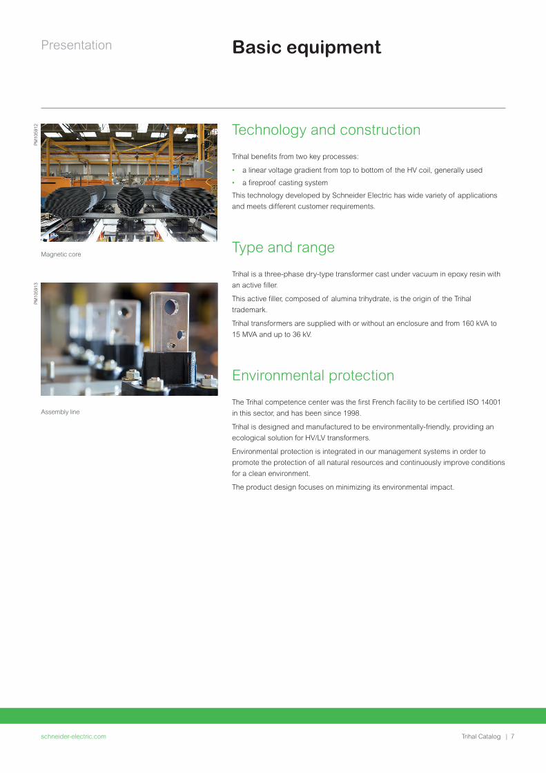
Presentation
schneider-electriccom | 9Trihal Catalog
Standard design Possible adaptation
Accessories bull Standard 4 bi-directional flat rollers 4 lifting holes 4 carriage holes on the sub-base 2 earthing points rating plate
bull Most common options Anti-vibration pads remote communication for thermal relay marshalling box earthing ball surge arresters
Locking device for plug-in bushings current transformers automatic voltage regulator panel On Load Tap Changer special paint color for enclosure
Test certificate Routine tests in accordance with IEC 60076-11 bull Type tests in accordance with IEC 60076-11 temperature rise test lightning impulse test
bull Special tests in accordance with IEC 60076-11 noise level measurement short-circuit test
bull Others seismic test resistance climatic environmental or fire class tests
Standards and configurations
Technology and construction
schneider-electriccom10 | Trihal Catalog
Technology
schneider-electriccom | 11Trihal Catalog
Technology
Manufacturing process 12
Magnetic core 12
LV winding 12
HV winding 13
HV casting system 13
HV coil casting process 14
HV support wedges 14
schneider-electriccom12 | Trihal Catalog
Technology
Magnetic core
The magnetic core is made from laminated grain-oriented silicon steel
The choice and grade of steel and the cutting pattern and method of assembly
minimize the loss level and the no-load current resulting in a very low noise level
Once assembled it is protected against corrosion
LV winding
The LV winding is made of either aluminium or copper foil to eliminate axial stress
under short-circuit conditions the foil is insulated by a Class F inter-layer film pre-
impregnated with heat-activated epoxy resin
The ends of the windings are protected and insulated using end packing made of
Class F materials
The whole winding is polymerized by being placed in an autoclave for 2 hours at
130degC which guarantees
bull outstanding resistance to harsh industrial atmospheres
bull excellent dielectric withstand
bull very good resistance to radial stress under short-circuit conditions
Each LV winding ends in a tin-plated aluminum or copper connection point
enabling connections to be made without using a contact interface
Magnetic core being assembled
LV winding with foil technology
Manufacturing process
Control of the industrial process very low partial discharge rate (le 5 pC)
PM
1059
14P
M10
5915
Technology
schneider-electriccom | 13Trihal Catalog
HV winding
The HV winding is usually wound from insulated aluminum or copper wire using a
method developed and patented by Schneider Electric ldquoa linear voltage gradient
from top to bottomrdquo
For higher currents the MV winding can be wound using ldquostriprdquo technology
These methods are used to obtain very low stress levels between adjacent
conductors
This winding is casted and molded under vacuum using Class F filling and
fireproofed resin the Trihal casting system
These processes give coils very high dielectric properties with very low partial
discharge level (guaranteed le5 Pc)(1) which is a decisive factor in influencing the
transformerrsquos life span and its lightning impulse withstand(2)
HV tapping points on the copper connection bars enable connections to be made
without using a contact interface (grease bi-metallic strip)
HV casting system
The system provides a vacuum-cast coating of fire-resistant filled resin a
technology developed and patented by Schneider Electric
The Class F casting system comprises
bull A bisphenol-based epoxy resin with sufficient viscosity to ensure excellent impregnation of the windings
bull An anhydride hardener ensures very good thermal and mechanical properties A flexibilizing additive gives the casting system the necessary elasticity to prevent cracking during operation
bull An active powdered filler consisting of silica and especially of alumina trihydrate thoroughly mixed with the resin and the hardener
bull Silica which reinforces the castingrsquos mechanical strength and improves heat dissipation
The alumina trihydrate guarantees the Trihal transformerrsquos intrinsic fire performance
Alumina trihydrate produces 3 fire-retardant effects which occur in the event of
calcination of the casting system (when the transformer is exposed to flames)
bull 1st fire-retardant effect refracting shield of alumina
bull 2nd fire-retardant effect barrier of water vapor
bull 3rd fire-retardant effect temperature held below the fire point
The result of all 3 fire-retardant effects is immediate self-extinguishing of the Trihal
transformer
In addition to its dielectric qualities the casting system gives the Trihal transformer
excellent self-extinguishing fire resistance and excellent environmental protection
against harsh industrial atmospheres
(1) Validated in external laboratory
(2) It is important to note that the level of partial discharge remains the same throughout the
transformerrsquos service life
HV winding with strip technology
Manufacturing processP
M10
5916
HV casting process
PM
1059
17
schneider-electriccom14 | Trihal Catalog
Technology
HV coil casting process
The process from proportioning the resin through to polymerization is fully
controlled by microprocessor preventing any inopportune manual operation
The alumina trihydrate and the silica are vacuum-dried and degassed to eliminate
all traces of humidity and air which could degrade the casting systemrsquos dielectric
characteristics
Half is mixed with the resin and half with the hardener under hard vacuum and at a
controlled temperature to give two homogenous pre-mixes
Another thin film degassing precedes the final mixing Vacuum casting is then
carried out in dried and pre-heated molds at an optimal impregnation temperature
The polymerization cycle begins with gelification at 80degC and ends with long
polymerization at 140degC
These temperatures are close to those of a transformer in service enabling
mechanical stresses to be eliminated which could lead to the coating cracking
HV coil support wedges
The high voltage winding is centered on the magnetic core and held in place
vertically by an efficient wedging system Thanks to the unique design of these
wedges they can be assembled in a variety of ways to suit different levels of HV
insulation
The wedges are designed according to customersrsquo needs to cope with different
environmental and mechanical conditions (seismic withstand vibration etc)
HV coil support wedges
Manufacturing processP
M10
5918
Notes
schneider-electriccom | 15Trihal Catalog
schneider-electriccom16 | Trihal Catalog
Options and accessories
schneider-electriccom | 17Trihal Catalog
Options and accessories
Options 18
Trihal CastCast 18
Trihal LVLV up to 400 kVA - 11 kV 18
Thermal Protection 19
T thermal protection using PT100 sensors 19
Z thermal protection using PTC sensors 20
Forced Ventilation 21
Connections 22
Low voltage connections 22
High voltage connections 22
High voltage surge arresters 23
Vibration damping 23
Protective Enclosure 24
IP protection indices 24
IK protection indices 24
Options and accessories
schneider-electriccom18 | Trihal Catalog
Options
Trihal Cast Cast
Trihal Cast Cast Cast Resin transformers provide high reliability and long durability
with both MV and LV windings casted under vacuum It is a perfect solution for
harsh environmental conditions such as high pollution or humidity It also provides
enhanced mechanical and thermal features
Application fields
bull OampG MMM
bull Utilities Power plants Water Nuclear
bull Infrastructure Public and commercial buildings such as Airports Hospitals etc
bull Small Industries Textile Automotive Pharmaceutics Food etc
Trihal LVLV up to 400 kVA - 11 kV
Trihal LVLV Cast Resin transformers provide reliability and longevity in harsh
environmental conditions such as high pollution or humidity It adapts to significant
temperature and charge variation constraints
Description
Trihal LVLV is suitable for
bull Earthing transformer
bull Change of earthing system
bull Isolate network disturbances
bull Change of network voltage
bull Galvanic isolation
bull Energy conversion
bull Dimmer monitoring
bull High power transformer pre-magnetization
Application fields
bull Buildings
bull Industry
bull Oil amp Gas
bull Marine
bull Secure Networks
Trihal CastCast benefits
bull Guaranteed against fire hazards (self-extinguishing)
bull Totally insensitive to harsh environments (pollution or condensation)
bull Easy and quick to install with a minimum maintenance
bull Enhances the mechanical stability and shock withstandability during the thermal overloads
bull Adapts itself to significant temperature and load changes
Trihal LVLV benefits
bull Guaranteed against fire hazards (self-extinguishing)
bull Totally insensitive to harsh environments (pollution or condensation)
bull Easy and quick to install with a minimum maintenance
Trihal LVLV
PM
1054
34
Options and accessories
schneider-electriccom | 19Trihal Catalog
The Trihal cast resin transformer can be protected by monitoring the winding
temperature
This monitoring is done by
bull PT100 sensors + associated relay for alarm and trip and real-time temperature
monitoring
bull PTC sensors + associated relay for alarm and trip
T thermal protection using PT100 sensors
This thermal protection device gives a digital display of the winding temperatures
and includes
bull PT100 sensors
- The main feature of a PT100 sensor is that it gives the real-time
temperature on a scale of 0degC to 200degC see graph opposite
(accuracy 05 of the measurement scale 1 degree)
- Temperature control and display functions are performed via a digital
thermometer The 3 sensors each comprising 1 white wire and 2 red wires
are installed in the live part of the Trihal transformer with 1 located on each
phase
- They are placed in a tube allowing them to be replaced if necessary
bull 1 terminal block for connecting the PT100 sensors to the T digital
thermometer
- The terminal block is equipped with a plug-in connector PT100 sensors are
supplied connected to the terminal block fixed to the top of the transformer
bull 1 T digital thermometer characterized by 3 independent circuits
- 2 of the circuits monitor the temperature captured by the PT100 sensors
one for alarm 1 the other for alarm 2
When the temperature reaches 140degC (or 150degC) the alarm 1 information
(or alarm 2tripping) is processed by 2 independent output relays
equipped with changeover contacts
The position of these relays is indicated by 2 diodes (LEDs)
- The third circuit monitors sensor or electrical supply failure
The corresponding relay (FAULT) which is independent and equipped
with changeover contacts is instantly switched as soon as the device is
supplied with power Its position is also indicated by a diode (LED)
The purpose of a FAN output is to control starting of tangential fans in the event of
forced ventilation of the transformer (AF) this option is shown on page 21
An additional input (CH4) can be connected to a sensor outside the transformer (not
supplied) intended to measure the ambient temperature in the HVLV substation
A digital output (RS 232 or 485) or a 4-20 mA analog output is available for
connection to a PLC or computer
A FAN 2 output is available as an option to control starting of an additional fan
The T digital thermometer is delivered with an installation manual
Resistance
Temperature
Typical graph of a PT100 sensor
Thermal protection
Please note since the transformer is thermal Class F the user has responsibility for setting the T digital thermometer with a maximum temperature of 140degC for alarm 1 and 150degC for alarm 2 (tripping)Failure to comply with these maximum temperatures absolves Schneider Electric of any liability for damage that could possibly be incurred by the transformer
DM
1052
00D
M10
5201
Schematic diagram for the T digital thermometer
terminal block mounted on the transformertransformer columns
PT100 outPT100 sensors fitted in the transformerPT100 in
FAN 2 ventilation outside the transformer
alarm 1 140degCalarm 2 150degCmonitoring of sensor failurestransformer ventilation (AF) 130degC
PT100 sensors outside the transformer
TBTC
TBTC
PT100 outPT100 in
RS 232 orRS 485 seriesoutput
FAN 2
AC - DC
24-220 V supply
AL 1
AL 1AL 2FAULTFAN
AL 2 FAULT FAN
Options and accessories
schneider-electriccom20 | Trihal Catalog
Terminal block for connecting sensors to the electronic converter
threshold
Resistance
Temperature
Typical graph of a PTC sensor
Thermal protectionD
M10
5202 Z thermal protection using PTC sensors
The standard version for naturally cooled (AN) transformers comprises
bull 2 PTC sensor sets positive temperature coefficient thermistors mounted
in series the first set for alarm 1 the second set for alarm 2
The PTC sensor resistance increases very steeply at a rated and factory-set
threshold temperature which is not adjustable (see graph opposite) This abrupt
increase is detected by a Z electronic converter
These sensors are installed in the live part of the Trihal transformer with one
alarm 1 sensor and one alarm 2 sensor on each phase They are placed in a
tube allowing them to be replaced as necessary
bull 1 terminal block for connecting the PTC sensors to the Z electronic
converter The terminal is equipped with a plug-in connector The PTC sensors
are supplied connected to the terminal attached to the top of the transformer
bull 1 Z electronic converter characterized by 3 independent measurement
circuits 2 of these circuits respectively control the variation in resistance in
the 2 PTC sensor sets When the temperature increases too much the alarm 1
(or alarm 2) information is processed respectively by the 2 independent output
relays equipped with a changeover contact the status of these 2 relays is
indicated via 2 LED diodes
The third measurement circuit is shunted by a resistor R outside the terminal
block it can control a third set of PTC sensors as long as this resistor is
removed In this case (ldquoforced airrdquo option available on request) the FAN
information is processed by a third independent output relay equipped with a
closing contact and is intended to control fans the position of this relay is shown
by an LED diode marked FAN
In the event of one of these 3 sensor circuits failing (power failure or short-
circuit) an LED diode marked SENSOR lights up and indication of the
incriminated circuit flashes An LED diode marked ON signals the presence of
voltage to the terminal block
Tra
nsf
orm
er
conn
ectio
n te
rmin
al
3 PTCsensorsAlarm 2
3 PTCsensorsAlarm 1
1 2 3 4 5 6 7 8 9 1 0
R
ON
SENSOR
ALARM 2
ALARM 1
FAN
RESETTEST
K0
K1K0
K2
T TT2
K2
24 21 22 14 11 12 08 05
K1 K 0
T1 T0
Ala
rm 2
Ala
rm 1
FanA
l1
power supplyto measurement
circuitsAlarm 2150degC
Alarm 1140degC
Third measurement circuitshunted by a resistor(on request 130degC PTCsensors for the fan)
A1 A2
ACDC 24-240V 5060 Hz
Please note the polarity for direct current
Z thermal protection connection diagram (normal use) equipment de-energized
DM
1052
03P
M10
5919
Options and accessories
schneider-electriccom | 21Trihal Catalog
Forced Ventilation
Force-ventilated transformer in IP31 enclosure
In the event of a temporary overload to avoid overheating of the windings it is
possible to install forced ventilation
It is then possible to increase the transformer power up to 40
In this case the following points must be considered
bull the cross-sections of the cables and Prefabricated Busbar Trunking (PBT)
bull the rating of the transformerrsquos protective circuit breaker
bull the size of the inlet and outlet air vents in the transformer room
bull the life span of fans in service
This option includes the supply of
bull 2 sets of tangential fans pre-cabled and connected to a single power
connector per set
bull 1 temperature measurement device either Z or T type
For Z type a third set of PTC sensors is added to the standard thermal
protection instead of the R resistor which originally shunted the third Z converter
measurement circuit (see diagram shown in the Z thermal protection option)
For T type the digital converter comprises an output (FAN) intended to start the
tangential fans (see diagram shown in the T thermal protection option)
This option includes depending on transformer type
bull a wiring box mounted outside the protective enclosure to which sensors and
power supplies for the fan sets are connected on a terminal block
bull a control cabinet supplied separately (transformer IP00) or mounted on the
protective enclosure including
- motor protection fuses
- starting contactors
- thermal protection device
This unit is connected to the temperature sensors and fan sets if the transformer is
supplied with an enclosure
PM
1059
20
Options and accessories
schneider-electriccom22 | Trihal Catalog
Connection
Low voltage connection
Cable ducting interface
Connection using Prefabricated Busbar Trunking (PBT) provides advantages in
terms of safety and also saves time during connection
This solution ensures maximum safety for people and property due to its
outstanding fire behaviour in line with that of Trihal It also ensures the absence of
halogenated products which is not the case for cabling
The option includes the connection interface together with the junction block with
the whole assembly delivered already mounted on the LV cable connectors
If the protective enclosure is provided a removable aluminum plate is screwed to
the roof vertical relative to the junction block
It will be adapted on site in order to fit the sealing system connecting the PBT If the
transformer enclosure is supplied the sealing system is supplied with the PBT
Additional cable connectors
Additional cable connections can be provided according to the number of the
cables
High voltage connection
Plug-in bushings
Plug-in bushings can be provided for the HV plug-in connectors They can be fitted
bull on a horizontal panel on the top of the HV side for transformers without a
protective enclosure (IP00)
bull on the enclosure roof HV side for transformers with a protective enclosure
A locking system for the connectors can also be supplied and installed in plug-in
bushings
Tangential fans on IP00
HV connections
PM
1059
21P
M10
5922
Options and accessories
schneider-electriccom | 23Trihal Catalog
Connection
High voltage surge arresters
If the installation is likely to be subjected to overvoltage of any kind (atmospheric
or switching) the transformer must be protected by phase-to-earth surge
arresters installed directly on the transformerrsquos HV connection terminals (either at
the top or the bottom)
It is essential to install these surge arresters
bull where the lightning impact level Nk is greater than 25 The risk of direct or
induced atmospheric overvoltage is directly proportional to Nk
bull during occasional switching (less than 10 operations a year) of a transformer
with a weak load or during a magnetization phase
It is also highly recommended to install them
where the substation is supplied by a network including overhead parts then a
cable longer than 20 m (case of an overhead-underground network)
Surge arresters can be installed in an IP 31 enclosure or even on existing
equipment provided that insulation distances are adhered to
Vibration damping
Roller anti-vibration pads
This accessory placed under the rollers avoids vibrations being transmitted from
the transformer to its environment
Damper unit
This device is installed instead of the roller and enables transmission of vibrations
to the transformer environment to be attenuated
High voltage surge arresters on the lower part
PM
1059
23
Anti-damping accessories
PM
1054
81P
M10
5479
Options and accessories
schneider-electriccom24 | Trihal Catalog
The IP and IK protective indices refer to the following criteria
IP protection indicesFirst Figure Second Figure
definition protection against solid bodies
protection against liquids
scale 0 to 6 0 to 8
IP 31 protection against solid bodies 25 mm
protects against vertical splashing by water
IP 21 protection againstsolid bodies 12 mm
protects against vertical splashing by water
IP 35 protection against solid bodies 25 mm
protects against water jets from all directions
IP 44 protection against solid bodies 1 mm
protects against water jets from all directions
IK protection indicesdefinition protection against mechanical impact
scale (1) 0 to 10
IK7 protection against mechanical impact lt=2 joules
IK10 protection against mechanical impact lt=20 joules
(1) 0 = no protection
With IP 35 and IP 44 transformers can be installed outdoors
Bracket for HV cables entering the bottom of the enclosureWhere required an HV cable bracket is available as an option to guide and support
cables entering the enclosure from the bottom via a removable screw-on aluminum
plate
Protective enclosure IP31 IK7
Protective EnclosureP
M10
5924
Notes
schneider-electriccom | 25Trihal Catalog
schneider-electriccom26 | Trihal Catalog
Tests and technical information
schneider-electriccom | 27Trihal Catalog
Tests and technical information
Tests 28
C3 Climatic Test 28
E3 Environmental Test 28
Fire Withstand 29
Partial Discharge le 5pC 29
Electrical Test 30
EcoDesign Regulation EU 548-2014 31
Tests and technical information
schneider-electriccom28 | Trihal Catalog
C3 climatic tests Trihal takes climatic testing to a new level
The highest certification described by IEC 60076-11 C2 imposes thermal shock
testing to a maximum of -25degC
Trihal passes the same tests at -50degC ensuring optimal performance even in
extreme climates
Lowest ambient temperatures
bull Operation -50degC
bull Storage -50degC
Benefits
bull Resistance to thermal shock
bull Optimum performance under severe ambient conditions
bull Superior behaviour on load changes
bull Extended service life
E3 environmental testTest conducted in two parts according to standards IEC 60076-11 and
IEC 60076-16
Condensation test
bull 6 hours with 95 humidity (by indirect spraying of water with conductivity of
between 36 and 4 Sm)
bull Induced voltage test
Humidity penetration test
bull 6 days at 50degC with 90 (+-5) humidity
bull Dielectric tests
bull Visual inspection
C2 thermal shock test carried out at -50degC
PM
1026
77
E3 environmental test
PM
1026
78
Tests
The new worldwide quality reference C3E3F1 with partial discharge le 5pC
Tests and technical information
schneider-electriccom | 29Trihal Catalog
Tests
F1 fire withstandThe fire behaviour test is conducted in a specific test chamber according to the
procedure described in standard IEC60076-11
bull 1 tank of ethyl alcohol (sufficient quantity for 20 mins combustion) burns under
the tested coil
bull 1 panel heater in front of the tested coil
bull 1 reflector concentric to the coil is fitted opposite the panel heater
The 2 fire-proof effects of the resin used in Trihal made it
possible to observe
bull Immediate self-extinguishing of Trihal as soon as the flames from the alcohol
tank die down and the panel heater is switched off
bull Absence of halogen products toxic emissions and opaque smoke
Partial discharge le 5pCA partial discharge is the dissipation of energy caused by the build-up of
localized electrical field intensity
These phenomena defined by standard IEC 60270 cause the insulation to
deteriorate progressively and can lead to electrical breakdown
The integrity of the transformer insulation is confirmed during Partial Discharge
Analysis and used as a tool to judge the state of the device and the quality of its
manufacture
As proof of our progress in terms of quality the acceptance criteria applicable to
all new Trihal are now le 10 pC during routine tests or le 5 pC in the case of special
tests ordered by the customer according to standard IEC 60076-11
F1 fire withstand tests
PM
1026
80P
M10
2679
Partial discharge test reports
PM
1026
82
PM
1026
81
Tests and technical information
schneider-electriccom30 | Trihal Catalog
Electrical testsThese tests verify the contractual electrical characteristics They include
Routine tests
These tests are systematically carried out on all Trihal transformers at the end of
manufacturing and are subject to an official test report
They comprise
bull Measurement of characteristics
- winding resistance
- transformation ratio and vector group
- impedance voltage
- load losses
- no-load losses and no-load current
bull Dielectric tests
- applied voltage tests 10 kV as standard in LV
- induced voltage tests at 25 Un
- measurement of partial discharge
Type tests and special tests
On request as per relevant standards
These are carried out on request and at the customerrsquos expense
bull Lightning test
Done as standard for 36 kV insulation level and high keraunic level
bull Short-circuit tests
bull Noise level measurements
bull Others on request
Routine test lab
TestsP
M10
5925
Tests and technical information
schneider-electriccom | 31Trihal Catalog
EcoDesign Regulation EU 548-2014
ecodesign
EcoDesign is a European Union regulation which came into force on 11th June
2014 in the 28 countries of the European Union
This new legislation imposes within the EU the maximum level of losses for
transformers placed on the market or commissioned from 1st July 2015 and
purchased after 11th June 2014
After the date of entry into force manufacturers should not enter into new
framework contracts for transformers with energy efficiency specifications below
the minimum requirements outlined in the regulation
Framework contracts signed before 11th June 2014 can continue until the end date
even with deliveries after 1st July 2015
bull EcoDesign has two major objectives for the Transformer product
bull Reducing electrical losses (1st phase in 20152nd phase in 2021)
bull Clarifying and improving the visibility of indication of performance
bull Harmonization of maximum loss levels in the European Union
bull Efficiency request on medium-power transformers for the first time
The following equipment is affected
bull All transformers exceeding 1 kVA and with voltage higher than 1 kV
bull Oil Distribution and Dry-type transformers (le 3150 kVA) with high voltage
winding above 11 kV and up to 36 kV
bull Medium power and Large power transformers gt 3150 kVA and higher than 36
kV (limited to 10 MVA 36 kV for Dry-type Transformers)
Special transformers are not affected by this regulation (please refer to restriction
list for details)
bull Loss levels to be applied (reference of MV le 24 kV and LV le 11 kV)
bull ODT and CRT not covered by reference transformers
(additional losses allowed compared to standard loss ranges)
Authorized loss levels for Oil Distribution and Dry-type Transformers (le 3150 kVA)
PM
1059
26
Maximum loss levels
Rated power
Tier 1 from 01072015
Tier 2 from 01072021
Pole-mounted 25 50 and 100 kVA AoCk AoBk
160 kVA CoCk+32 Co-10 Ck+32
200 250 and 315 kVA CoCk BoBk
Oil-Immersed transformers
le 1000 kVA AoCkAo-10 Ak
gt 1000 kVA AoBk
Dry-Type transformers
le 630 kVA AoBkAo-10 Ak
gt 630 kVA AoAk
Tests and technical information
schneider-electriccom32 | Trihal Catalog
Eg ODT 630 kVA 33 kV - 410 V max losses to be considered A0+15 - Ck +10
Other requirements Impact on no-load lossescompared to standard losses table
Impact on load lossescompared to standard losses table
MV insulation level le 24 kV
LV insulation level gt 11 kV
10 10
MV insulation level = 36 kV
LV insulation level le 11 kV
15 10
MV insulation level = 36 kV
LV insulation level gt 11 kV
20 15
Dual voltage on MV winding and
85 power limitation on higher MV voltage
No impact No impact
Dual voltage on MV winding and
85 power limitation on higher LV voltage
No impact No impact
Dual voltage on one winding (MV or LV)
and full power on all voltages considered
15 10
Dual voltage on both windings (MV and LV) 20 20
Transformers with tappings for operation while energized
(such as Voltage Regulation Distribution Transformers)
20
(reduced to +10 in 01-07-2021)
5
EcoDesign Regulation EU 548-2014
Notes
schneider-electriccom | 33Trihal Catalog
schneider-electriccom34 | Trihal Catalog
Internet
schneider-electriccom | 35Trihal Catalog
Internet
Transformer selector 36
Total Cost of Ownership (TCO) tool 36
Internet
schneider-electriccom36 | Trihal Catalog
Internet tools
Transformer selector Choosing the right transformer for the job can be a real nightmare This web
selector has ben developed to help you find it more easily
Select your segment function type and voltage range and hey presto Your best-
in-class MV transformer is here
Total Cost of Ownership (TCO)When purchasing a transformer and especially when comparing two different
solutions the right choice is driven by an economic analysis of the equipment
Total Cost of Ownership giving the cost of transformer operation throughout their
life including purchasing operating and maintenance costs
Basically some simplification can be done when comparing two different
transformers with the same technology installation maintenance and
decommissioning will generate the same costs and then be excluded from the
comparison
The calculation has to take into consideration changes in the cost of energy during
the transformer life span The interest rate also has to be considered as stated
below
A pragmatic way to choose the right transformer
httpwwwschneider-electriccomentoolstco-for-transformer
Calculation of the TCO
The simplified calculation formula of the Total Cost of Ownership is as
follows
Total Cost of Ownership =
Purchasing Price + No-Load Losses Cost + Load Losses Cost
With
No-Load Losses Cost NLLC = (1+i)^n -1i(1+i)^n C Time
Load Losses Cost LLC = (1+i)^n -1i(1+i)^n C Time Load factorsup2
Where
i interest rate [year]
n lifetime [years]
C kWh price [USDkWh]
Time number of hours in a year [hyear] = 8760
Load factor average load of the transformer during its life time
Calculate TCO
PrintSave PDF Help FeedbackCompare TCO of Transformers
Product Family (Dry Type Oil immersed orMPTLPT)
DRY TYPE
Payback Period Configuration coherence
Transformer Total Cost of Ownership 136484 190526
Purchase price
Load losses (PK)
Load losses Level
No load losses Level
No load losses (PO)
Maximum LV isulation level
Maximum HV isulation level
Rated Power kVA
kV
kV
W
W
EUR 30000 25000
9000 12000
890
Ak
AAA0
lt=24
lt=11
2100
EUR
Yrs 142
1000
Units Transformer 1 Transformer 2
CompareTCO (2)
VIEW COMPARISON GRAPH
200
150
100
50
00 5
142
10
Time of use (yrs)
TR 2
TR 1
Tota
l Cos
t of
Ow
ners
hip
(k)
(E
UR
)
15 20
PM
1059
27P
M10
5928
schneider-electriccom | 37Trihal Catalog
This international web site allows you to access all the Schneider Electric solutions and product information viabull Comprehensive descriptionsbull Range datasheetsbull A download areabull Product selectors
You can also access information dedicated to your business and contact your Schneider Electric country support
PM
1036
87
TOOLS
schneider-electriccom38 | Trihal Catalog
Web selector
Training
This site allows you to access the Schneider Electric products in just two clicks via a comprehensive range of datasheets with direct links tobull Complete libraries technical documents catalogs
FAQs brochuresbull Selection guides from the e-catalogbull Product discovery sites and their animationsYou will also find illustrated overviews news to which you can subscribe and a list of country contacts
Training allows you to acquire the expertise (installation design work with power on etc) to increase efficiency and improve customer service
The training catalog includes beginnerrsquos courses in electrical distribution knowledge of MV and LV switchgear operation and maintenance of installations and design of LV installations to give a few examples
TOOLS
Notes
schneider-electriccom | 39Trihal Catalog
NRJED315663EN
Life
Is
On
Sch
ne
ide
r E
lect
ric
is a
tra
de
ma
rk a
nd
th
e p
rop
ert
y o
f Sch
ne
ide
r E
lect
ric
SE
its
su
bsi
dia
rie
s a
nd
aff
iliat
ed
co
mp
an
ies
All
rig
hts
rese
rve
d
Schneider Electric Industries SAS
35 rue Joseph Monier92500 Rueil-Malmaison FranceTel +33 (0)1 41 29 70 00
wwwschneider-electriccom
SAS capital social 928 298 512 euro 954 503 439 RCS Nanterre
23 08 2016
copy2016 Schneider Electric All Rights ReservedAll trademarks are owned by Schneider Electric Industries SAS or its affiliated companies

Technology
schneider-electriccom | 13Trihal Catalog
HV winding
The HV winding is usually wound from insulated aluminum or copper wire using a
method developed and patented by Schneider Electric ldquoa linear voltage gradient
from top to bottomrdquo
For higher currents the MV winding can be wound using ldquostriprdquo technology
These methods are used to obtain very low stress levels between adjacent
conductors
This winding is casted and molded under vacuum using Class F filling and
fireproofed resin the Trihal casting system
These processes give coils very high dielectric properties with very low partial
discharge level (guaranteed le5 Pc)(1) which is a decisive factor in influencing the
transformerrsquos life span and its lightning impulse withstand(2)
HV tapping points on the copper connection bars enable connections to be made
without using a contact interface (grease bi-metallic strip)
HV casting system
The system provides a vacuum-cast coating of fire-resistant filled resin a
technology developed and patented by Schneider Electric
The Class F casting system comprises
bull A bisphenol-based epoxy resin with sufficient viscosity to ensure excellent impregnation of the windings
bull An anhydride hardener ensures very good thermal and mechanical properties A flexibilizing additive gives the casting system the necessary elasticity to prevent cracking during operation
bull An active powdered filler consisting of silica and especially of alumina trihydrate thoroughly mixed with the resin and the hardener
bull Silica which reinforces the castingrsquos mechanical strength and improves heat dissipation
The alumina trihydrate guarantees the Trihal transformerrsquos intrinsic fire performance
Alumina trihydrate produces 3 fire-retardant effects which occur in the event of
calcination of the casting system (when the transformer is exposed to flames)
bull 1st fire-retardant effect refracting shield of alumina
bull 2nd fire-retardant effect barrier of water vapor
bull 3rd fire-retardant effect temperature held below the fire point
The result of all 3 fire-retardant effects is immediate self-extinguishing of the Trihal
transformer
In addition to its dielectric qualities the casting system gives the Trihal transformer
excellent self-extinguishing fire resistance and excellent environmental protection
against harsh industrial atmospheres
(1) Validated in external laboratory
(2) It is important to note that the level of partial discharge remains the same throughout the
transformerrsquos service life
HV winding with strip technology
Manufacturing processP
M10
5916
HV casting process
PM
1059
17
schneider-electriccom14 | Trihal Catalog
Technology
HV coil casting process
The process from proportioning the resin through to polymerization is fully
controlled by microprocessor preventing any inopportune manual operation
The alumina trihydrate and the silica are vacuum-dried and degassed to eliminate
all traces of humidity and air which could degrade the casting systemrsquos dielectric
characteristics
Half is mixed with the resin and half with the hardener under hard vacuum and at a
controlled temperature to give two homogenous pre-mixes
Another thin film degassing precedes the final mixing Vacuum casting is then
carried out in dried and pre-heated molds at an optimal impregnation temperature
The polymerization cycle begins with gelification at 80degC and ends with long
polymerization at 140degC
These temperatures are close to those of a transformer in service enabling
mechanical stresses to be eliminated which could lead to the coating cracking
HV coil support wedges
The high voltage winding is centered on the magnetic core and held in place
vertically by an efficient wedging system Thanks to the unique design of these
wedges they can be assembled in a variety of ways to suit different levels of HV
insulation
The wedges are designed according to customersrsquo needs to cope with different
environmental and mechanical conditions (seismic withstand vibration etc)
HV coil support wedges
Manufacturing processP
M10
5918
Notes
schneider-electriccom | 15Trihal Catalog
schneider-electriccom16 | Trihal Catalog
Options and accessories
schneider-electriccom | 17Trihal Catalog
Options and accessories
Options 18
Trihal CastCast 18
Trihal LVLV up to 400 kVA - 11 kV 18
Thermal Protection 19
T thermal protection using PT100 sensors 19
Z thermal protection using PTC sensors 20
Forced Ventilation 21
Connections 22
Low voltage connections 22
High voltage connections 22
High voltage surge arresters 23
Vibration damping 23
Protective Enclosure 24
IP protection indices 24
IK protection indices 24
Options and accessories
schneider-electriccom18 | Trihal Catalog
Options
Trihal Cast Cast
Trihal Cast Cast Cast Resin transformers provide high reliability and long durability
with both MV and LV windings casted under vacuum It is a perfect solution for
harsh environmental conditions such as high pollution or humidity It also provides
enhanced mechanical and thermal features
Application fields
bull OampG MMM
bull Utilities Power plants Water Nuclear
bull Infrastructure Public and commercial buildings such as Airports Hospitals etc
bull Small Industries Textile Automotive Pharmaceutics Food etc
Trihal LVLV up to 400 kVA - 11 kV
Trihal LVLV Cast Resin transformers provide reliability and longevity in harsh
environmental conditions such as high pollution or humidity It adapts to significant
temperature and charge variation constraints
Description
Trihal LVLV is suitable for
bull Earthing transformer
bull Change of earthing system
bull Isolate network disturbances
bull Change of network voltage
bull Galvanic isolation
bull Energy conversion
bull Dimmer monitoring
bull High power transformer pre-magnetization
Application fields
bull Buildings
bull Industry
bull Oil amp Gas
bull Marine
bull Secure Networks
Trihal CastCast benefits
bull Guaranteed against fire hazards (self-extinguishing)
bull Totally insensitive to harsh environments (pollution or condensation)
bull Easy and quick to install with a minimum maintenance
bull Enhances the mechanical stability and shock withstandability during the thermal overloads
bull Adapts itself to significant temperature and load changes
Trihal LVLV benefits
bull Guaranteed against fire hazards (self-extinguishing)
bull Totally insensitive to harsh environments (pollution or condensation)
bull Easy and quick to install with a minimum maintenance
Trihal LVLV
PM
1054
34
Options and accessories
schneider-electriccom | 19Trihal Catalog
The Trihal cast resin transformer can be protected by monitoring the winding
temperature
This monitoring is done by
bull PT100 sensors + associated relay for alarm and trip and real-time temperature
monitoring
bull PTC sensors + associated relay for alarm and trip
T thermal protection using PT100 sensors
This thermal protection device gives a digital display of the winding temperatures
and includes
bull PT100 sensors
- The main feature of a PT100 sensor is that it gives the real-time
temperature on a scale of 0degC to 200degC see graph opposite
(accuracy 05 of the measurement scale 1 degree)
- Temperature control and display functions are performed via a digital
thermometer The 3 sensors each comprising 1 white wire and 2 red wires
are installed in the live part of the Trihal transformer with 1 located on each
phase
- They are placed in a tube allowing them to be replaced if necessary
bull 1 terminal block for connecting the PT100 sensors to the T digital
thermometer
- The terminal block is equipped with a plug-in connector PT100 sensors are
supplied connected to the terminal block fixed to the top of the transformer
bull 1 T digital thermometer characterized by 3 independent circuits
- 2 of the circuits monitor the temperature captured by the PT100 sensors
one for alarm 1 the other for alarm 2
When the temperature reaches 140degC (or 150degC) the alarm 1 information
(or alarm 2tripping) is processed by 2 independent output relays
equipped with changeover contacts
The position of these relays is indicated by 2 diodes (LEDs)
- The third circuit monitors sensor or electrical supply failure
The corresponding relay (FAULT) which is independent and equipped
with changeover contacts is instantly switched as soon as the device is
supplied with power Its position is also indicated by a diode (LED)
The purpose of a FAN output is to control starting of tangential fans in the event of
forced ventilation of the transformer (AF) this option is shown on page 21
An additional input (CH4) can be connected to a sensor outside the transformer (not
supplied) intended to measure the ambient temperature in the HVLV substation
A digital output (RS 232 or 485) or a 4-20 mA analog output is available for
connection to a PLC or computer
A FAN 2 output is available as an option to control starting of an additional fan
The T digital thermometer is delivered with an installation manual
Resistance
Temperature
Typical graph of a PT100 sensor
Thermal protection
Please note since the transformer is thermal Class F the user has responsibility for setting the T digital thermometer with a maximum temperature of 140degC for alarm 1 and 150degC for alarm 2 (tripping)Failure to comply with these maximum temperatures absolves Schneider Electric of any liability for damage that could possibly be incurred by the transformer
DM
1052
00D
M10
5201
Schematic diagram for the T digital thermometer
terminal block mounted on the transformertransformer columns
PT100 outPT100 sensors fitted in the transformerPT100 in
FAN 2 ventilation outside the transformer
alarm 1 140degCalarm 2 150degCmonitoring of sensor failurestransformer ventilation (AF) 130degC
PT100 sensors outside the transformer
TBTC
TBTC
PT100 outPT100 in
RS 232 orRS 485 seriesoutput
FAN 2
AC - DC
24-220 V supply
AL 1
AL 1AL 2FAULTFAN
AL 2 FAULT FAN
Options and accessories
schneider-electriccom20 | Trihal Catalog
Terminal block for connecting sensors to the electronic converter
threshold
Resistance
Temperature
Typical graph of a PTC sensor
Thermal protectionD
M10
5202 Z thermal protection using PTC sensors
The standard version for naturally cooled (AN) transformers comprises
bull 2 PTC sensor sets positive temperature coefficient thermistors mounted
in series the first set for alarm 1 the second set for alarm 2
The PTC sensor resistance increases very steeply at a rated and factory-set
threshold temperature which is not adjustable (see graph opposite) This abrupt
increase is detected by a Z electronic converter
These sensors are installed in the live part of the Trihal transformer with one
alarm 1 sensor and one alarm 2 sensor on each phase They are placed in a
tube allowing them to be replaced as necessary
bull 1 terminal block for connecting the PTC sensors to the Z electronic
converter The terminal is equipped with a plug-in connector The PTC sensors
are supplied connected to the terminal attached to the top of the transformer
bull 1 Z electronic converter characterized by 3 independent measurement
circuits 2 of these circuits respectively control the variation in resistance in
the 2 PTC sensor sets When the temperature increases too much the alarm 1
(or alarm 2) information is processed respectively by the 2 independent output
relays equipped with a changeover contact the status of these 2 relays is
indicated via 2 LED diodes
The third measurement circuit is shunted by a resistor R outside the terminal
block it can control a third set of PTC sensors as long as this resistor is
removed In this case (ldquoforced airrdquo option available on request) the FAN
information is processed by a third independent output relay equipped with a
closing contact and is intended to control fans the position of this relay is shown
by an LED diode marked FAN
In the event of one of these 3 sensor circuits failing (power failure or short-
circuit) an LED diode marked SENSOR lights up and indication of the
incriminated circuit flashes An LED diode marked ON signals the presence of
voltage to the terminal block
Tra
nsf
orm
er
conn
ectio
n te
rmin
al
3 PTCsensorsAlarm 2
3 PTCsensorsAlarm 1
1 2 3 4 5 6 7 8 9 1 0
R
ON
SENSOR
ALARM 2
ALARM 1
FAN
RESETTEST
K0
K1K0
K2
T TT2
K2
24 21 22 14 11 12 08 05
K1 K 0
T1 T0
Ala
rm 2
Ala
rm 1
FanA
l1
power supplyto measurement
circuitsAlarm 2150degC
Alarm 1140degC
Third measurement circuitshunted by a resistor(on request 130degC PTCsensors for the fan)
A1 A2
ACDC 24-240V 5060 Hz
Please note the polarity for direct current
Z thermal protection connection diagram (normal use) equipment de-energized
DM
1052
03P
M10
5919
Options and accessories
schneider-electriccom | 21Trihal Catalog
Forced Ventilation
Force-ventilated transformer in IP31 enclosure
In the event of a temporary overload to avoid overheating of the windings it is
possible to install forced ventilation
It is then possible to increase the transformer power up to 40
In this case the following points must be considered
bull the cross-sections of the cables and Prefabricated Busbar Trunking (PBT)
bull the rating of the transformerrsquos protective circuit breaker
bull the size of the inlet and outlet air vents in the transformer room
bull the life span of fans in service
This option includes the supply of
bull 2 sets of tangential fans pre-cabled and connected to a single power
connector per set
bull 1 temperature measurement device either Z or T type
For Z type a third set of PTC sensors is added to the standard thermal
protection instead of the R resistor which originally shunted the third Z converter
measurement circuit (see diagram shown in the Z thermal protection option)
For T type the digital converter comprises an output (FAN) intended to start the
tangential fans (see diagram shown in the T thermal protection option)
This option includes depending on transformer type
bull a wiring box mounted outside the protective enclosure to which sensors and
power supplies for the fan sets are connected on a terminal block
bull a control cabinet supplied separately (transformer IP00) or mounted on the
protective enclosure including
- motor protection fuses
- starting contactors
- thermal protection device
This unit is connected to the temperature sensors and fan sets if the transformer is
supplied with an enclosure
PM
1059
20
Options and accessories
schneider-electriccom22 | Trihal Catalog
Connection
Low voltage connection
Cable ducting interface
Connection using Prefabricated Busbar Trunking (PBT) provides advantages in
terms of safety and also saves time during connection
This solution ensures maximum safety for people and property due to its
outstanding fire behaviour in line with that of Trihal It also ensures the absence of
halogenated products which is not the case for cabling
The option includes the connection interface together with the junction block with
the whole assembly delivered already mounted on the LV cable connectors
If the protective enclosure is provided a removable aluminum plate is screwed to
the roof vertical relative to the junction block
It will be adapted on site in order to fit the sealing system connecting the PBT If the
transformer enclosure is supplied the sealing system is supplied with the PBT
Additional cable connectors
Additional cable connections can be provided according to the number of the
cables
High voltage connection
Plug-in bushings
Plug-in bushings can be provided for the HV plug-in connectors They can be fitted
bull on a horizontal panel on the top of the HV side for transformers without a
protective enclosure (IP00)
bull on the enclosure roof HV side for transformers with a protective enclosure
A locking system for the connectors can also be supplied and installed in plug-in
bushings
Tangential fans on IP00
HV connections
PM
1059
21P
M10
5922
Options and accessories
schneider-electriccom | 23Trihal Catalog
Connection
High voltage surge arresters
If the installation is likely to be subjected to overvoltage of any kind (atmospheric
or switching) the transformer must be protected by phase-to-earth surge
arresters installed directly on the transformerrsquos HV connection terminals (either at
the top or the bottom)
It is essential to install these surge arresters
bull where the lightning impact level Nk is greater than 25 The risk of direct or
induced atmospheric overvoltage is directly proportional to Nk
bull during occasional switching (less than 10 operations a year) of a transformer
with a weak load or during a magnetization phase
It is also highly recommended to install them
where the substation is supplied by a network including overhead parts then a
cable longer than 20 m (case of an overhead-underground network)
Surge arresters can be installed in an IP 31 enclosure or even on existing
equipment provided that insulation distances are adhered to
Vibration damping
Roller anti-vibration pads
This accessory placed under the rollers avoids vibrations being transmitted from
the transformer to its environment
Damper unit
This device is installed instead of the roller and enables transmission of vibrations
to the transformer environment to be attenuated
High voltage surge arresters on the lower part
PM
1059
23
Anti-damping accessories
PM
1054
81P
M10
5479
Options and accessories
schneider-electriccom24 | Trihal Catalog
The IP and IK protective indices refer to the following criteria
IP protection indicesFirst Figure Second Figure
definition protection against solid bodies
protection against liquids
scale 0 to 6 0 to 8
IP 31 protection against solid bodies 25 mm
protects against vertical splashing by water
IP 21 protection againstsolid bodies 12 mm
protects against vertical splashing by water
IP 35 protection against solid bodies 25 mm
protects against water jets from all directions
IP 44 protection against solid bodies 1 mm
protects against water jets from all directions
IK protection indicesdefinition protection against mechanical impact
scale (1) 0 to 10
IK7 protection against mechanical impact lt=2 joules
IK10 protection against mechanical impact lt=20 joules
(1) 0 = no protection
With IP 35 and IP 44 transformers can be installed outdoors
Bracket for HV cables entering the bottom of the enclosureWhere required an HV cable bracket is available as an option to guide and support
cables entering the enclosure from the bottom via a removable screw-on aluminum
plate
Protective enclosure IP31 IK7
Protective EnclosureP
M10
5924
Notes
schneider-electriccom | 25Trihal Catalog
schneider-electriccom26 | Trihal Catalog
Tests and technical information
schneider-electriccom | 27Trihal Catalog
Tests and technical information
Tests 28
C3 Climatic Test 28
E3 Environmental Test 28
Fire Withstand 29
Partial Discharge le 5pC 29
Electrical Test 30
EcoDesign Regulation EU 548-2014 31
Tests and technical information
schneider-electriccom28 | Trihal Catalog
C3 climatic tests Trihal takes climatic testing to a new level
The highest certification described by IEC 60076-11 C2 imposes thermal shock
testing to a maximum of -25degC
Trihal passes the same tests at -50degC ensuring optimal performance even in
extreme climates
Lowest ambient temperatures
bull Operation -50degC
bull Storage -50degC
Benefits
bull Resistance to thermal shock
bull Optimum performance under severe ambient conditions
bull Superior behaviour on load changes
bull Extended service life
E3 environmental testTest conducted in two parts according to standards IEC 60076-11 and
IEC 60076-16
Condensation test
bull 6 hours with 95 humidity (by indirect spraying of water with conductivity of
between 36 and 4 Sm)
bull Induced voltage test
Humidity penetration test
bull 6 days at 50degC with 90 (+-5) humidity
bull Dielectric tests
bull Visual inspection
C2 thermal shock test carried out at -50degC
PM
1026
77
E3 environmental test
PM
1026
78
Tests
The new worldwide quality reference C3E3F1 with partial discharge le 5pC
Tests and technical information
schneider-electriccom | 29Trihal Catalog
Tests
F1 fire withstandThe fire behaviour test is conducted in a specific test chamber according to the
procedure described in standard IEC60076-11
bull 1 tank of ethyl alcohol (sufficient quantity for 20 mins combustion) burns under
the tested coil
bull 1 panel heater in front of the tested coil
bull 1 reflector concentric to the coil is fitted opposite the panel heater
The 2 fire-proof effects of the resin used in Trihal made it
possible to observe
bull Immediate self-extinguishing of Trihal as soon as the flames from the alcohol
tank die down and the panel heater is switched off
bull Absence of halogen products toxic emissions and opaque smoke
Partial discharge le 5pCA partial discharge is the dissipation of energy caused by the build-up of
localized electrical field intensity
These phenomena defined by standard IEC 60270 cause the insulation to
deteriorate progressively and can lead to electrical breakdown
The integrity of the transformer insulation is confirmed during Partial Discharge
Analysis and used as a tool to judge the state of the device and the quality of its
manufacture
As proof of our progress in terms of quality the acceptance criteria applicable to
all new Trihal are now le 10 pC during routine tests or le 5 pC in the case of special
tests ordered by the customer according to standard IEC 60076-11
F1 fire withstand tests
PM
1026
80P
M10
2679
Partial discharge test reports
PM
1026
82
PM
1026
81
Tests and technical information
schneider-electriccom30 | Trihal Catalog
Electrical testsThese tests verify the contractual electrical characteristics They include
Routine tests
These tests are systematically carried out on all Trihal transformers at the end of
manufacturing and are subject to an official test report
They comprise
bull Measurement of characteristics
- winding resistance
- transformation ratio and vector group
- impedance voltage
- load losses
- no-load losses and no-load current
bull Dielectric tests
- applied voltage tests 10 kV as standard in LV
- induced voltage tests at 25 Un
- measurement of partial discharge
Type tests and special tests
On request as per relevant standards
These are carried out on request and at the customerrsquos expense
bull Lightning test
Done as standard for 36 kV insulation level and high keraunic level
bull Short-circuit tests
bull Noise level measurements
bull Others on request
Routine test lab
TestsP
M10
5925
Tests and technical information
schneider-electriccom | 31Trihal Catalog
EcoDesign Regulation EU 548-2014
ecodesign
EcoDesign is a European Union regulation which came into force on 11th June
2014 in the 28 countries of the European Union
This new legislation imposes within the EU the maximum level of losses for
transformers placed on the market or commissioned from 1st July 2015 and
purchased after 11th June 2014
After the date of entry into force manufacturers should not enter into new
framework contracts for transformers with energy efficiency specifications below
the minimum requirements outlined in the regulation
Framework contracts signed before 11th June 2014 can continue until the end date
even with deliveries after 1st July 2015
bull EcoDesign has two major objectives for the Transformer product
bull Reducing electrical losses (1st phase in 20152nd phase in 2021)
bull Clarifying and improving the visibility of indication of performance
bull Harmonization of maximum loss levels in the European Union
bull Efficiency request on medium-power transformers for the first time
The following equipment is affected
bull All transformers exceeding 1 kVA and with voltage higher than 1 kV
bull Oil Distribution and Dry-type transformers (le 3150 kVA) with high voltage
winding above 11 kV and up to 36 kV
bull Medium power and Large power transformers gt 3150 kVA and higher than 36
kV (limited to 10 MVA 36 kV for Dry-type Transformers)
Special transformers are not affected by this regulation (please refer to restriction
list for details)
bull Loss levels to be applied (reference of MV le 24 kV and LV le 11 kV)
bull ODT and CRT not covered by reference transformers
(additional losses allowed compared to standard loss ranges)
Authorized loss levels for Oil Distribution and Dry-type Transformers (le 3150 kVA)
PM
1059
26
Maximum loss levels
Rated power
Tier 1 from 01072015
Tier 2 from 01072021
Pole-mounted 25 50 and 100 kVA AoCk AoBk
160 kVA CoCk+32 Co-10 Ck+32
200 250 and 315 kVA CoCk BoBk
Oil-Immersed transformers
le 1000 kVA AoCkAo-10 Ak
gt 1000 kVA AoBk
Dry-Type transformers
le 630 kVA AoBkAo-10 Ak
gt 630 kVA AoAk
Tests and technical information
schneider-electriccom32 | Trihal Catalog
Eg ODT 630 kVA 33 kV - 410 V max losses to be considered A0+15 - Ck +10
Other requirements Impact on no-load lossescompared to standard losses table
Impact on load lossescompared to standard losses table
MV insulation level le 24 kV
LV insulation level gt 11 kV
10 10
MV insulation level = 36 kV
LV insulation level le 11 kV
15 10
MV insulation level = 36 kV
LV insulation level gt 11 kV
20 15
Dual voltage on MV winding and
85 power limitation on higher MV voltage
No impact No impact
Dual voltage on MV winding and
85 power limitation on higher LV voltage
No impact No impact
Dual voltage on one winding (MV or LV)
and full power on all voltages considered
15 10
Dual voltage on both windings (MV and LV) 20 20
Transformers with tappings for operation while energized
(such as Voltage Regulation Distribution Transformers)
20
(reduced to +10 in 01-07-2021)
5
EcoDesign Regulation EU 548-2014
Notes
schneider-electriccom | 33Trihal Catalog
schneider-electriccom34 | Trihal Catalog
Internet
schneider-electriccom | 35Trihal Catalog
Internet
Transformer selector 36
Total Cost of Ownership (TCO) tool 36
Internet
schneider-electriccom36 | Trihal Catalog
Internet tools
Transformer selector Choosing the right transformer for the job can be a real nightmare This web
selector has ben developed to help you find it more easily
Select your segment function type and voltage range and hey presto Your best-
in-class MV transformer is here
Total Cost of Ownership (TCO)When purchasing a transformer and especially when comparing two different
solutions the right choice is driven by an economic analysis of the equipment
Total Cost of Ownership giving the cost of transformer operation throughout their
life including purchasing operating and maintenance costs
Basically some simplification can be done when comparing two different
transformers with the same technology installation maintenance and
decommissioning will generate the same costs and then be excluded from the
comparison
The calculation has to take into consideration changes in the cost of energy during
the transformer life span The interest rate also has to be considered as stated
below
A pragmatic way to choose the right transformer
httpwwwschneider-electriccomentoolstco-for-transformer
Calculation of the TCO
The simplified calculation formula of the Total Cost of Ownership is as
follows
Total Cost of Ownership =
Purchasing Price + No-Load Losses Cost + Load Losses Cost
With
No-Load Losses Cost NLLC = (1+i)^n -1i(1+i)^n C Time
Load Losses Cost LLC = (1+i)^n -1i(1+i)^n C Time Load factorsup2
Where
i interest rate [year]
n lifetime [years]
C kWh price [USDkWh]
Time number of hours in a year [hyear] = 8760
Load factor average load of the transformer during its life time
Calculate TCO
PrintSave PDF Help FeedbackCompare TCO of Transformers
Product Family (Dry Type Oil immersed orMPTLPT)
DRY TYPE
Payback Period Configuration coherence
Transformer Total Cost of Ownership 136484 190526
Purchase price
Load losses (PK)
Load losses Level
No load losses Level
No load losses (PO)
Maximum LV isulation level
Maximum HV isulation level
Rated Power kVA
kV
kV
W
W
EUR 30000 25000
9000 12000
890
Ak
AAA0
lt=24
lt=11
2100
EUR
Yrs 142
1000
Units Transformer 1 Transformer 2
CompareTCO (2)
VIEW COMPARISON GRAPH
200
150
100
50
00 5
142
10
Time of use (yrs)
TR 2
TR 1
Tota
l Cos
t of
Ow
ners
hip
(k)
(E
UR
)
15 20
PM
1059
27P
M10
5928
schneider-electriccom | 37Trihal Catalog
This international web site allows you to access all the Schneider Electric solutions and product information viabull Comprehensive descriptionsbull Range datasheetsbull A download areabull Product selectors
You can also access information dedicated to your business and contact your Schneider Electric country support
PM
1036
87
TOOLS
schneider-electriccom38 | Trihal Catalog
Web selector
Training
This site allows you to access the Schneider Electric products in just two clicks via a comprehensive range of datasheets with direct links tobull Complete libraries technical documents catalogs
FAQs brochuresbull Selection guides from the e-catalogbull Product discovery sites and their animationsYou will also find illustrated overviews news to which you can subscribe and a list of country contacts
Training allows you to acquire the expertise (installation design work with power on etc) to increase efficiency and improve customer service
The training catalog includes beginnerrsquos courses in electrical distribution knowledge of MV and LV switchgear operation and maintenance of installations and design of LV installations to give a few examples
TOOLS
Notes
schneider-electriccom | 39Trihal Catalog
NRJED315663EN
Life
Is
On
Sch
ne
ide
r E
lect
ric
is a
tra
de
ma
rk a
nd
th
e p
rop
ert
y o
f Sch
ne
ide
r E
lect
ric
SE
its
su
bsi
dia
rie
s a
nd
aff
iliat
ed
co
mp
an
ies
All
rig
hts
rese
rve
d
Schneider Electric Industries SAS
35 rue Joseph Monier92500 Rueil-Malmaison FranceTel +33 (0)1 41 29 70 00
wwwschneider-electriccom
SAS capital social 928 298 512 euro 954 503 439 RCS Nanterre
23 08 2016
copy2016 Schneider Electric All Rights ReservedAll trademarks are owned by Schneider Electric Industries SAS or its affiliated companies

Notes
schneider-electriccom | 15Trihal Catalog
schneider-electriccom16 | Trihal Catalog
Options and accessories
schneider-electriccom | 17Trihal Catalog
Options and accessories
Options 18
Trihal CastCast 18
Trihal LVLV up to 400 kVA - 11 kV 18
Thermal Protection 19
T thermal protection using PT100 sensors 19
Z thermal protection using PTC sensors 20
Forced Ventilation 21
Connections 22
Low voltage connections 22
High voltage connections 22
High voltage surge arresters 23
Vibration damping 23
Protective Enclosure 24
IP protection indices 24
IK protection indices 24
Options and accessories
schneider-electriccom18 | Trihal Catalog
Options
Trihal Cast Cast
Trihal Cast Cast Cast Resin transformers provide high reliability and long durability
with both MV and LV windings casted under vacuum It is a perfect solution for
harsh environmental conditions such as high pollution or humidity It also provides
enhanced mechanical and thermal features
Application fields
bull OampG MMM
bull Utilities Power plants Water Nuclear
bull Infrastructure Public and commercial buildings such as Airports Hospitals etc
bull Small Industries Textile Automotive Pharmaceutics Food etc
Trihal LVLV up to 400 kVA - 11 kV
Trihal LVLV Cast Resin transformers provide reliability and longevity in harsh
environmental conditions such as high pollution or humidity It adapts to significant
temperature and charge variation constraints
Description
Trihal LVLV is suitable for
bull Earthing transformer
bull Change of earthing system
bull Isolate network disturbances
bull Change of network voltage
bull Galvanic isolation
bull Energy conversion
bull Dimmer monitoring
bull High power transformer pre-magnetization
Application fields
bull Buildings
bull Industry
bull Oil amp Gas
bull Marine
bull Secure Networks
Trihal CastCast benefits
bull Guaranteed against fire hazards (self-extinguishing)
bull Totally insensitive to harsh environments (pollution or condensation)
bull Easy and quick to install with a minimum maintenance
bull Enhances the mechanical stability and shock withstandability during the thermal overloads
bull Adapts itself to significant temperature and load changes
Trihal LVLV benefits
bull Guaranteed against fire hazards (self-extinguishing)
bull Totally insensitive to harsh environments (pollution or condensation)
bull Easy and quick to install with a minimum maintenance
Trihal LVLV
PM
1054
34
Options and accessories
schneider-electriccom | 19Trihal Catalog
The Trihal cast resin transformer can be protected by monitoring the winding
temperature
This monitoring is done by
bull PT100 sensors + associated relay for alarm and trip and real-time temperature
monitoring
bull PTC sensors + associated relay for alarm and trip
T thermal protection using PT100 sensors
This thermal protection device gives a digital display of the winding temperatures
and includes
bull PT100 sensors
- The main feature of a PT100 sensor is that it gives the real-time
temperature on a scale of 0degC to 200degC see graph opposite
(accuracy 05 of the measurement scale 1 degree)
- Temperature control and display functions are performed via a digital
thermometer The 3 sensors each comprising 1 white wire and 2 red wires
are installed in the live part of the Trihal transformer with 1 located on each
phase
- They are placed in a tube allowing them to be replaced if necessary
bull 1 terminal block for connecting the PT100 sensors to the T digital
thermometer
- The terminal block is equipped with a plug-in connector PT100 sensors are
supplied connected to the terminal block fixed to the top of the transformer
bull 1 T digital thermometer characterized by 3 independent circuits
- 2 of the circuits monitor the temperature captured by the PT100 sensors
one for alarm 1 the other for alarm 2
When the temperature reaches 140degC (or 150degC) the alarm 1 information
(or alarm 2tripping) is processed by 2 independent output relays
equipped with changeover contacts
The position of these relays is indicated by 2 diodes (LEDs)
- The third circuit monitors sensor or electrical supply failure
The corresponding relay (FAULT) which is independent and equipped
with changeover contacts is instantly switched as soon as the device is
supplied with power Its position is also indicated by a diode (LED)
The purpose of a FAN output is to control starting of tangential fans in the event of
forced ventilation of the transformer (AF) this option is shown on page 21
An additional input (CH4) can be connected to a sensor outside the transformer (not
supplied) intended to measure the ambient temperature in the HVLV substation
A digital output (RS 232 or 485) or a 4-20 mA analog output is available for
connection to a PLC or computer
A FAN 2 output is available as an option to control starting of an additional fan
The T digital thermometer is delivered with an installation manual
Resistance
Temperature
Typical graph of a PT100 sensor
Thermal protection
Please note since the transformer is thermal Class F the user has responsibility for setting the T digital thermometer with a maximum temperature of 140degC for alarm 1 and 150degC for alarm 2 (tripping)Failure to comply with these maximum temperatures absolves Schneider Electric of any liability for damage that could possibly be incurred by the transformer
DM
1052
00D
M10
5201
Schematic diagram for the T digital thermometer
terminal block mounted on the transformertransformer columns
PT100 outPT100 sensors fitted in the transformerPT100 in
FAN 2 ventilation outside the transformer
alarm 1 140degCalarm 2 150degCmonitoring of sensor failurestransformer ventilation (AF) 130degC
PT100 sensors outside the transformer
TBTC
TBTC
PT100 outPT100 in
RS 232 orRS 485 seriesoutput
FAN 2
AC - DC
24-220 V supply
AL 1
AL 1AL 2FAULTFAN
AL 2 FAULT FAN
Options and accessories
schneider-electriccom20 | Trihal Catalog
Terminal block for connecting sensors to the electronic converter
threshold
Resistance
Temperature
Typical graph of a PTC sensor
Thermal protectionD
M10
5202 Z thermal protection using PTC sensors
The standard version for naturally cooled (AN) transformers comprises
bull 2 PTC sensor sets positive temperature coefficient thermistors mounted
in series the first set for alarm 1 the second set for alarm 2
The PTC sensor resistance increases very steeply at a rated and factory-set
threshold temperature which is not adjustable (see graph opposite) This abrupt
increase is detected by a Z electronic converter
These sensors are installed in the live part of the Trihal transformer with one
alarm 1 sensor and one alarm 2 sensor on each phase They are placed in a
tube allowing them to be replaced as necessary
bull 1 terminal block for connecting the PTC sensors to the Z electronic
converter The terminal is equipped with a plug-in connector The PTC sensors
are supplied connected to the terminal attached to the top of the transformer
bull 1 Z electronic converter characterized by 3 independent measurement
circuits 2 of these circuits respectively control the variation in resistance in
the 2 PTC sensor sets When the temperature increases too much the alarm 1
(or alarm 2) information is processed respectively by the 2 independent output
relays equipped with a changeover contact the status of these 2 relays is
indicated via 2 LED diodes
The third measurement circuit is shunted by a resistor R outside the terminal
block it can control a third set of PTC sensors as long as this resistor is
removed In this case (ldquoforced airrdquo option available on request) the FAN
information is processed by a third independent output relay equipped with a
closing contact and is intended to control fans the position of this relay is shown
by an LED diode marked FAN
In the event of one of these 3 sensor circuits failing (power failure or short-
circuit) an LED diode marked SENSOR lights up and indication of the
incriminated circuit flashes An LED diode marked ON signals the presence of
voltage to the terminal block
Tra
nsf
orm
er
conn
ectio
n te
rmin
al
3 PTCsensorsAlarm 2
3 PTCsensorsAlarm 1
1 2 3 4 5 6 7 8 9 1 0
R
ON
SENSOR
ALARM 2
ALARM 1
FAN
RESETTEST
K0
K1K0
K2
T TT2
K2
24 21 22 14 11 12 08 05
K1 K 0
T1 T0
Ala
rm 2
Ala
rm 1
FanA
l1
power supplyto measurement
circuitsAlarm 2150degC
Alarm 1140degC
Third measurement circuitshunted by a resistor(on request 130degC PTCsensors for the fan)
A1 A2
ACDC 24-240V 5060 Hz
Please note the polarity for direct current
Z thermal protection connection diagram (normal use) equipment de-energized
DM
1052
03P
M10
5919
Options and accessories
schneider-electriccom | 21Trihal Catalog
Forced Ventilation
Force-ventilated transformer in IP31 enclosure
In the event of a temporary overload to avoid overheating of the windings it is
possible to install forced ventilation
It is then possible to increase the transformer power up to 40
In this case the following points must be considered
bull the cross-sections of the cables and Prefabricated Busbar Trunking (PBT)
bull the rating of the transformerrsquos protective circuit breaker
bull the size of the inlet and outlet air vents in the transformer room
bull the life span of fans in service
This option includes the supply of
bull 2 sets of tangential fans pre-cabled and connected to a single power
connector per set
bull 1 temperature measurement device either Z or T type
For Z type a third set of PTC sensors is added to the standard thermal
protection instead of the R resistor which originally shunted the third Z converter
measurement circuit (see diagram shown in the Z thermal protection option)
For T type the digital converter comprises an output (FAN) intended to start the
tangential fans (see diagram shown in the T thermal protection option)
This option includes depending on transformer type
bull a wiring box mounted outside the protective enclosure to which sensors and
power supplies for the fan sets are connected on a terminal block
bull a control cabinet supplied separately (transformer IP00) or mounted on the
protective enclosure including
- motor protection fuses
- starting contactors
- thermal protection device
This unit is connected to the temperature sensors and fan sets if the transformer is
supplied with an enclosure
PM
1059
20
Options and accessories
schneider-electriccom22 | Trihal Catalog
Connection
Low voltage connection
Cable ducting interface
Connection using Prefabricated Busbar Trunking (PBT) provides advantages in
terms of safety and also saves time during connection
This solution ensures maximum safety for people and property due to its
outstanding fire behaviour in line with that of Trihal It also ensures the absence of
halogenated products which is not the case for cabling
The option includes the connection interface together with the junction block with
the whole assembly delivered already mounted on the LV cable connectors
If the protective enclosure is provided a removable aluminum plate is screwed to
the roof vertical relative to the junction block
It will be adapted on site in order to fit the sealing system connecting the PBT If the
transformer enclosure is supplied the sealing system is supplied with the PBT
Additional cable connectors
Additional cable connections can be provided according to the number of the
cables
High voltage connection
Plug-in bushings
Plug-in bushings can be provided for the HV plug-in connectors They can be fitted
bull on a horizontal panel on the top of the HV side for transformers without a
protective enclosure (IP00)
bull on the enclosure roof HV side for transformers with a protective enclosure
A locking system for the connectors can also be supplied and installed in plug-in
bushings
Tangential fans on IP00
HV connections
PM
1059
21P
M10
5922
Options and accessories
schneider-electriccom | 23Trihal Catalog
Connection
High voltage surge arresters
If the installation is likely to be subjected to overvoltage of any kind (atmospheric
or switching) the transformer must be protected by phase-to-earth surge
arresters installed directly on the transformerrsquos HV connection terminals (either at
the top or the bottom)
It is essential to install these surge arresters
bull where the lightning impact level Nk is greater than 25 The risk of direct or
induced atmospheric overvoltage is directly proportional to Nk
bull during occasional switching (less than 10 operations a year) of a transformer
with a weak load or during a magnetization phase
It is also highly recommended to install them
where the substation is supplied by a network including overhead parts then a
cable longer than 20 m (case of an overhead-underground network)
Surge arresters can be installed in an IP 31 enclosure or even on existing
equipment provided that insulation distances are adhered to
Vibration damping
Roller anti-vibration pads
This accessory placed under the rollers avoids vibrations being transmitted from
the transformer to its environment
Damper unit
This device is installed instead of the roller and enables transmission of vibrations
to the transformer environment to be attenuated
High voltage surge arresters on the lower part
PM
1059
23
Anti-damping accessories
PM
1054
81P
M10
5479
Options and accessories
schneider-electriccom24 | Trihal Catalog
The IP and IK protective indices refer to the following criteria
IP protection indicesFirst Figure Second Figure
definition protection against solid bodies
protection against liquids
scale 0 to 6 0 to 8
IP 31 protection against solid bodies 25 mm
protects against vertical splashing by water
IP 21 protection againstsolid bodies 12 mm
protects against vertical splashing by water
IP 35 protection against solid bodies 25 mm
protects against water jets from all directions
IP 44 protection against solid bodies 1 mm
protects against water jets from all directions
IK protection indicesdefinition protection against mechanical impact
scale (1) 0 to 10
IK7 protection against mechanical impact lt=2 joules
IK10 protection against mechanical impact lt=20 joules
(1) 0 = no protection
With IP 35 and IP 44 transformers can be installed outdoors
Bracket for HV cables entering the bottom of the enclosureWhere required an HV cable bracket is available as an option to guide and support
cables entering the enclosure from the bottom via a removable screw-on aluminum
plate
Protective enclosure IP31 IK7
Protective EnclosureP
M10
5924
Notes
schneider-electriccom | 25Trihal Catalog
schneider-electriccom26 | Trihal Catalog
Tests and technical information
schneider-electriccom | 27Trihal Catalog
Tests and technical information
Tests 28
C3 Climatic Test 28
E3 Environmental Test 28
Fire Withstand 29
Partial Discharge le 5pC 29
Electrical Test 30
EcoDesign Regulation EU 548-2014 31
Tests and technical information
schneider-electriccom28 | Trihal Catalog
C3 climatic tests Trihal takes climatic testing to a new level
The highest certification described by IEC 60076-11 C2 imposes thermal shock
testing to a maximum of -25degC
Trihal passes the same tests at -50degC ensuring optimal performance even in
extreme climates
Lowest ambient temperatures
bull Operation -50degC
bull Storage -50degC
Benefits
bull Resistance to thermal shock
bull Optimum performance under severe ambient conditions
bull Superior behaviour on load changes
bull Extended service life
E3 environmental testTest conducted in two parts according to standards IEC 60076-11 and
IEC 60076-16
Condensation test
bull 6 hours with 95 humidity (by indirect spraying of water with conductivity of
between 36 and 4 Sm)
bull Induced voltage test
Humidity penetration test
bull 6 days at 50degC with 90 (+-5) humidity
bull Dielectric tests
bull Visual inspection
C2 thermal shock test carried out at -50degC
PM
1026
77
E3 environmental test
PM
1026
78
Tests
The new worldwide quality reference C3E3F1 with partial discharge le 5pC
Tests and technical information
schneider-electriccom | 29Trihal Catalog
Tests
F1 fire withstandThe fire behaviour test is conducted in a specific test chamber according to the
procedure described in standard IEC60076-11
bull 1 tank of ethyl alcohol (sufficient quantity for 20 mins combustion) burns under
the tested coil
bull 1 panel heater in front of the tested coil
bull 1 reflector concentric to the coil is fitted opposite the panel heater
The 2 fire-proof effects of the resin used in Trihal made it
possible to observe
bull Immediate self-extinguishing of Trihal as soon as the flames from the alcohol
tank die down and the panel heater is switched off
bull Absence of halogen products toxic emissions and opaque smoke
Partial discharge le 5pCA partial discharge is the dissipation of energy caused by the build-up of
localized electrical field intensity
These phenomena defined by standard IEC 60270 cause the insulation to
deteriorate progressively and can lead to electrical breakdown
The integrity of the transformer insulation is confirmed during Partial Discharge
Analysis and used as a tool to judge the state of the device and the quality of its
manufacture
As proof of our progress in terms of quality the acceptance criteria applicable to
all new Trihal are now le 10 pC during routine tests or le 5 pC in the case of special
tests ordered by the customer according to standard IEC 60076-11
F1 fire withstand tests
PM
1026
80P
M10
2679
Partial discharge test reports
PM
1026
82
PM
1026
81
Tests and technical information
schneider-electriccom30 | Trihal Catalog
Electrical testsThese tests verify the contractual electrical characteristics They include
Routine tests
These tests are systematically carried out on all Trihal transformers at the end of
manufacturing and are subject to an official test report
They comprise
bull Measurement of characteristics
- winding resistance
- transformation ratio and vector group
- impedance voltage
- load losses
- no-load losses and no-load current
bull Dielectric tests
- applied voltage tests 10 kV as standard in LV
- induced voltage tests at 25 Un
- measurement of partial discharge
Type tests and special tests
On request as per relevant standards
These are carried out on request and at the customerrsquos expense
bull Lightning test
Done as standard for 36 kV insulation level and high keraunic level
bull Short-circuit tests
bull Noise level measurements
bull Others on request
Routine test lab
TestsP
M10
5925
Tests and technical information
schneider-electriccom | 31Trihal Catalog
EcoDesign Regulation EU 548-2014
ecodesign
EcoDesign is a European Union regulation which came into force on 11th June
2014 in the 28 countries of the European Union
This new legislation imposes within the EU the maximum level of losses for
transformers placed on the market or commissioned from 1st July 2015 and
purchased after 11th June 2014
After the date of entry into force manufacturers should not enter into new
framework contracts for transformers with energy efficiency specifications below
the minimum requirements outlined in the regulation
Framework contracts signed before 11th June 2014 can continue until the end date
even with deliveries after 1st July 2015
bull EcoDesign has two major objectives for the Transformer product
bull Reducing electrical losses (1st phase in 20152nd phase in 2021)
bull Clarifying and improving the visibility of indication of performance
bull Harmonization of maximum loss levels in the European Union
bull Efficiency request on medium-power transformers for the first time
The following equipment is affected
bull All transformers exceeding 1 kVA and with voltage higher than 1 kV
bull Oil Distribution and Dry-type transformers (le 3150 kVA) with high voltage
winding above 11 kV and up to 36 kV
bull Medium power and Large power transformers gt 3150 kVA and higher than 36
kV (limited to 10 MVA 36 kV for Dry-type Transformers)
Special transformers are not affected by this regulation (please refer to restriction
list for details)
bull Loss levels to be applied (reference of MV le 24 kV and LV le 11 kV)
bull ODT and CRT not covered by reference transformers
(additional losses allowed compared to standard loss ranges)
Authorized loss levels for Oil Distribution and Dry-type Transformers (le 3150 kVA)
PM
1059
26
Maximum loss levels
Rated power
Tier 1 from 01072015
Tier 2 from 01072021
Pole-mounted 25 50 and 100 kVA AoCk AoBk
160 kVA CoCk+32 Co-10 Ck+32
200 250 and 315 kVA CoCk BoBk
Oil-Immersed transformers
le 1000 kVA AoCkAo-10 Ak
gt 1000 kVA AoBk
Dry-Type transformers
le 630 kVA AoBkAo-10 Ak
gt 630 kVA AoAk
Tests and technical information
schneider-electriccom32 | Trihal Catalog
Eg ODT 630 kVA 33 kV - 410 V max losses to be considered A0+15 - Ck +10
Other requirements Impact on no-load lossescompared to standard losses table
Impact on load lossescompared to standard losses table
MV insulation level le 24 kV
LV insulation level gt 11 kV
10 10
MV insulation level = 36 kV
LV insulation level le 11 kV
15 10
MV insulation level = 36 kV
LV insulation level gt 11 kV
20 15
Dual voltage on MV winding and
85 power limitation on higher MV voltage
No impact No impact
Dual voltage on MV winding and
85 power limitation on higher LV voltage
No impact No impact
Dual voltage on one winding (MV or LV)
and full power on all voltages considered
15 10
Dual voltage on both windings (MV and LV) 20 20
Transformers with tappings for operation while energized
(such as Voltage Regulation Distribution Transformers)
20
(reduced to +10 in 01-07-2021)
5
EcoDesign Regulation EU 548-2014
Notes
schneider-electriccom | 33Trihal Catalog
schneider-electriccom34 | Trihal Catalog
Internet
schneider-electriccom | 35Trihal Catalog
Internet
Transformer selector 36
Total Cost of Ownership (TCO) tool 36
Internet
schneider-electriccom36 | Trihal Catalog
Internet tools
Transformer selector Choosing the right transformer for the job can be a real nightmare This web
selector has ben developed to help you find it more easily
Select your segment function type and voltage range and hey presto Your best-
in-class MV transformer is here
Total Cost of Ownership (TCO)When purchasing a transformer and especially when comparing two different
solutions the right choice is driven by an economic analysis of the equipment
Total Cost of Ownership giving the cost of transformer operation throughout their
life including purchasing operating and maintenance costs
Basically some simplification can be done when comparing two different
transformers with the same technology installation maintenance and
decommissioning will generate the same costs and then be excluded from the
comparison
The calculation has to take into consideration changes in the cost of energy during
the transformer life span The interest rate also has to be considered as stated
below
A pragmatic way to choose the right transformer
httpwwwschneider-electriccomentoolstco-for-transformer
Calculation of the TCO
The simplified calculation formula of the Total Cost of Ownership is as
follows
Total Cost of Ownership =
Purchasing Price + No-Load Losses Cost + Load Losses Cost
With
No-Load Losses Cost NLLC = (1+i)^n -1i(1+i)^n C Time
Load Losses Cost LLC = (1+i)^n -1i(1+i)^n C Time Load factorsup2
Where
i interest rate [year]
n lifetime [years]
C kWh price [USDkWh]
Time number of hours in a year [hyear] = 8760
Load factor average load of the transformer during its life time
Calculate TCO
PrintSave PDF Help FeedbackCompare TCO of Transformers
Product Family (Dry Type Oil immersed orMPTLPT)
DRY TYPE
Payback Period Configuration coherence
Transformer Total Cost of Ownership 136484 190526
Purchase price
Load losses (PK)
Load losses Level
No load losses Level
No load losses (PO)
Maximum LV isulation level
Maximum HV isulation level
Rated Power kVA
kV
kV
W
W
EUR 30000 25000
9000 12000
890
Ak
AAA0
lt=24
lt=11
2100
EUR
Yrs 142
1000
Units Transformer 1 Transformer 2
CompareTCO (2)
VIEW COMPARISON GRAPH
200
150
100
50
00 5
142
10
Time of use (yrs)
TR 2
TR 1
Tota
l Cos
t of
Ow
ners
hip
(k)
(E
UR
)
15 20
PM
1059
27P
M10
5928
schneider-electriccom | 37Trihal Catalog
This international web site allows you to access all the Schneider Electric solutions and product information viabull Comprehensive descriptionsbull Range datasheetsbull A download areabull Product selectors
You can also access information dedicated to your business and contact your Schneider Electric country support
PM
1036
87
TOOLS
schneider-electriccom38 | Trihal Catalog
Web selector
Training
This site allows you to access the Schneider Electric products in just two clicks via a comprehensive range of datasheets with direct links tobull Complete libraries technical documents catalogs
FAQs brochuresbull Selection guides from the e-catalogbull Product discovery sites and their animationsYou will also find illustrated overviews news to which you can subscribe and a list of country contacts
Training allows you to acquire the expertise (installation design work with power on etc) to increase efficiency and improve customer service
The training catalog includes beginnerrsquos courses in electrical distribution knowledge of MV and LV switchgear operation and maintenance of installations and design of LV installations to give a few examples
TOOLS
Notes
schneider-electriccom | 39Trihal Catalog
NRJED315663EN
Life
Is
On
Sch
ne
ide
r E
lect
ric
is a
tra
de
ma
rk a
nd
th
e p
rop
ert
y o
f Sch
ne
ide
r E
lect
ric
SE
its
su
bsi
dia
rie
s a
nd
aff
iliat
ed
co
mp
an
ies
All
rig
hts
rese
rve
d
Schneider Electric Industries SAS
35 rue Joseph Monier92500 Rueil-Malmaison FranceTel +33 (0)1 41 29 70 00
wwwschneider-electriccom
SAS capital social 928 298 512 euro 954 503 439 RCS Nanterre
23 08 2016
copy2016 Schneider Electric All Rights ReservedAll trademarks are owned by Schneider Electric Industries SAS or its affiliated companies

Options and accessories
schneider-electriccom | 19Trihal Catalog
The Trihal cast resin transformer can be protected by monitoring the winding
temperature
This monitoring is done by
bull PT100 sensors + associated relay for alarm and trip and real-time temperature
monitoring
bull PTC sensors + associated relay for alarm and trip
T thermal protection using PT100 sensors
This thermal protection device gives a digital display of the winding temperatures
and includes
bull PT100 sensors
- The main feature of a PT100 sensor is that it gives the real-time
temperature on a scale of 0degC to 200degC see graph opposite
(accuracy 05 of the measurement scale 1 degree)
- Temperature control and display functions are performed via a digital
thermometer The 3 sensors each comprising 1 white wire and 2 red wires
are installed in the live part of the Trihal transformer with 1 located on each
phase
- They are placed in a tube allowing them to be replaced if necessary
bull 1 terminal block for connecting the PT100 sensors to the T digital
thermometer
- The terminal block is equipped with a plug-in connector PT100 sensors are
supplied connected to the terminal block fixed to the top of the transformer
bull 1 T digital thermometer characterized by 3 independent circuits
- 2 of the circuits monitor the temperature captured by the PT100 sensors
one for alarm 1 the other for alarm 2
When the temperature reaches 140degC (or 150degC) the alarm 1 information
(or alarm 2tripping) is processed by 2 independent output relays
equipped with changeover contacts
The position of these relays is indicated by 2 diodes (LEDs)
- The third circuit monitors sensor or electrical supply failure
The corresponding relay (FAULT) which is independent and equipped
with changeover contacts is instantly switched as soon as the device is
supplied with power Its position is also indicated by a diode (LED)
The purpose of a FAN output is to control starting of tangential fans in the event of
forced ventilation of the transformer (AF) this option is shown on page 21
An additional input (CH4) can be connected to a sensor outside the transformer (not
supplied) intended to measure the ambient temperature in the HVLV substation
A digital output (RS 232 or 485) or a 4-20 mA analog output is available for
connection to a PLC or computer
A FAN 2 output is available as an option to control starting of an additional fan
The T digital thermometer is delivered with an installation manual
Resistance
Temperature
Typical graph of a PT100 sensor
Thermal protection
Please note since the transformer is thermal Class F the user has responsibility for setting the T digital thermometer with a maximum temperature of 140degC for alarm 1 and 150degC for alarm 2 (tripping)Failure to comply with these maximum temperatures absolves Schneider Electric of any liability for damage that could possibly be incurred by the transformer
DM
1052
00D
M10
5201
Schematic diagram for the T digital thermometer
terminal block mounted on the transformertransformer columns
PT100 outPT100 sensors fitted in the transformerPT100 in
FAN 2 ventilation outside the transformer
alarm 1 140degCalarm 2 150degCmonitoring of sensor failurestransformer ventilation (AF) 130degC
PT100 sensors outside the transformer
TBTC
TBTC
PT100 outPT100 in
RS 232 orRS 485 seriesoutput
FAN 2
AC - DC
24-220 V supply
AL 1
AL 1AL 2FAULTFAN
AL 2 FAULT FAN
Options and accessories
schneider-electriccom20 | Trihal Catalog
Terminal block for connecting sensors to the electronic converter
threshold
Resistance
Temperature
Typical graph of a PTC sensor
Thermal protectionD
M10
5202 Z thermal protection using PTC sensors
The standard version for naturally cooled (AN) transformers comprises
bull 2 PTC sensor sets positive temperature coefficient thermistors mounted
in series the first set for alarm 1 the second set for alarm 2
The PTC sensor resistance increases very steeply at a rated and factory-set
threshold temperature which is not adjustable (see graph opposite) This abrupt
increase is detected by a Z electronic converter
These sensors are installed in the live part of the Trihal transformer with one
alarm 1 sensor and one alarm 2 sensor on each phase They are placed in a
tube allowing them to be replaced as necessary
bull 1 terminal block for connecting the PTC sensors to the Z electronic
converter The terminal is equipped with a plug-in connector The PTC sensors
are supplied connected to the terminal attached to the top of the transformer
bull 1 Z electronic converter characterized by 3 independent measurement
circuits 2 of these circuits respectively control the variation in resistance in
the 2 PTC sensor sets When the temperature increases too much the alarm 1
(or alarm 2) information is processed respectively by the 2 independent output
relays equipped with a changeover contact the status of these 2 relays is
indicated via 2 LED diodes
The third measurement circuit is shunted by a resistor R outside the terminal
block it can control a third set of PTC sensors as long as this resistor is
removed In this case (ldquoforced airrdquo option available on request) the FAN
information is processed by a third independent output relay equipped with a
closing contact and is intended to control fans the position of this relay is shown
by an LED diode marked FAN
In the event of one of these 3 sensor circuits failing (power failure or short-
circuit) an LED diode marked SENSOR lights up and indication of the
incriminated circuit flashes An LED diode marked ON signals the presence of
voltage to the terminal block
Tra
nsf
orm
er
conn
ectio
n te
rmin
al
3 PTCsensorsAlarm 2
3 PTCsensorsAlarm 1
1 2 3 4 5 6 7 8 9 1 0
R
ON
SENSOR
ALARM 2
ALARM 1
FAN
RESETTEST
K0
K1K0
K2
T TT2
K2
24 21 22 14 11 12 08 05
K1 K 0
T1 T0
Ala
rm 2
Ala
rm 1
FanA
l1
power supplyto measurement
circuitsAlarm 2150degC
Alarm 1140degC
Third measurement circuitshunted by a resistor(on request 130degC PTCsensors for the fan)
A1 A2
ACDC 24-240V 5060 Hz
Please note the polarity for direct current
Z thermal protection connection diagram (normal use) equipment de-energized
DM
1052
03P
M10
5919
Options and accessories
schneider-electriccom | 21Trihal Catalog
Forced Ventilation
Force-ventilated transformer in IP31 enclosure
In the event of a temporary overload to avoid overheating of the windings it is
possible to install forced ventilation
It is then possible to increase the transformer power up to 40
In this case the following points must be considered
bull the cross-sections of the cables and Prefabricated Busbar Trunking (PBT)
bull the rating of the transformerrsquos protective circuit breaker
bull the size of the inlet and outlet air vents in the transformer room
bull the life span of fans in service
This option includes the supply of
bull 2 sets of tangential fans pre-cabled and connected to a single power
connector per set
bull 1 temperature measurement device either Z or T type
For Z type a third set of PTC sensors is added to the standard thermal
protection instead of the R resistor which originally shunted the third Z converter
measurement circuit (see diagram shown in the Z thermal protection option)
For T type the digital converter comprises an output (FAN) intended to start the
tangential fans (see diagram shown in the T thermal protection option)
This option includes depending on transformer type
bull a wiring box mounted outside the protective enclosure to which sensors and
power supplies for the fan sets are connected on a terminal block
bull a control cabinet supplied separately (transformer IP00) or mounted on the
protective enclosure including
- motor protection fuses
- starting contactors
- thermal protection device
This unit is connected to the temperature sensors and fan sets if the transformer is
supplied with an enclosure
PM
1059
20
Options and accessories
schneider-electriccom22 | Trihal Catalog
Connection
Low voltage connection
Cable ducting interface
Connection using Prefabricated Busbar Trunking (PBT) provides advantages in
terms of safety and also saves time during connection
This solution ensures maximum safety for people and property due to its
outstanding fire behaviour in line with that of Trihal It also ensures the absence of
halogenated products which is not the case for cabling
The option includes the connection interface together with the junction block with
the whole assembly delivered already mounted on the LV cable connectors
If the protective enclosure is provided a removable aluminum plate is screwed to
the roof vertical relative to the junction block
It will be adapted on site in order to fit the sealing system connecting the PBT If the
transformer enclosure is supplied the sealing system is supplied with the PBT
Additional cable connectors
Additional cable connections can be provided according to the number of the
cables
High voltage connection
Plug-in bushings
Plug-in bushings can be provided for the HV plug-in connectors They can be fitted
bull on a horizontal panel on the top of the HV side for transformers without a
protective enclosure (IP00)
bull on the enclosure roof HV side for transformers with a protective enclosure
A locking system for the connectors can also be supplied and installed in plug-in
bushings
Tangential fans on IP00
HV connections
PM
1059
21P
M10
5922
Options and accessories
schneider-electriccom | 23Trihal Catalog
Connection
High voltage surge arresters
If the installation is likely to be subjected to overvoltage of any kind (atmospheric
or switching) the transformer must be protected by phase-to-earth surge
arresters installed directly on the transformerrsquos HV connection terminals (either at
the top or the bottom)
It is essential to install these surge arresters
bull where the lightning impact level Nk is greater than 25 The risk of direct or
induced atmospheric overvoltage is directly proportional to Nk
bull during occasional switching (less than 10 operations a year) of a transformer
with a weak load or during a magnetization phase
It is also highly recommended to install them
where the substation is supplied by a network including overhead parts then a
cable longer than 20 m (case of an overhead-underground network)
Surge arresters can be installed in an IP 31 enclosure or even on existing
equipment provided that insulation distances are adhered to
Vibration damping
Roller anti-vibration pads
This accessory placed under the rollers avoids vibrations being transmitted from
the transformer to its environment
Damper unit
This device is installed instead of the roller and enables transmission of vibrations
to the transformer environment to be attenuated
High voltage surge arresters on the lower part
PM
1059
23
Anti-damping accessories
PM
1054
81P
M10
5479
Options and accessories
schneider-electriccom24 | Trihal Catalog
The IP and IK protective indices refer to the following criteria
IP protection indicesFirst Figure Second Figure
definition protection against solid bodies
protection against liquids
scale 0 to 6 0 to 8
IP 31 protection against solid bodies 25 mm
protects against vertical splashing by water
IP 21 protection againstsolid bodies 12 mm
protects against vertical splashing by water
IP 35 protection against solid bodies 25 mm
protects against water jets from all directions
IP 44 protection against solid bodies 1 mm
protects against water jets from all directions
IK protection indicesdefinition protection against mechanical impact
scale (1) 0 to 10
IK7 protection against mechanical impact lt=2 joules
IK10 protection against mechanical impact lt=20 joules
(1) 0 = no protection
With IP 35 and IP 44 transformers can be installed outdoors
Bracket for HV cables entering the bottom of the enclosureWhere required an HV cable bracket is available as an option to guide and support
cables entering the enclosure from the bottom via a removable screw-on aluminum
plate
Protective enclosure IP31 IK7
Protective EnclosureP
M10
5924
Notes
schneider-electriccom | 25Trihal Catalog
schneider-electriccom26 | Trihal Catalog
Tests and technical information
schneider-electriccom | 27Trihal Catalog
Tests and technical information
Tests 28
C3 Climatic Test 28
E3 Environmental Test 28
Fire Withstand 29
Partial Discharge le 5pC 29
Electrical Test 30
EcoDesign Regulation EU 548-2014 31
Tests and technical information
schneider-electriccom28 | Trihal Catalog
C3 climatic tests Trihal takes climatic testing to a new level
The highest certification described by IEC 60076-11 C2 imposes thermal shock
testing to a maximum of -25degC
Trihal passes the same tests at -50degC ensuring optimal performance even in
extreme climates
Lowest ambient temperatures
bull Operation -50degC
bull Storage -50degC
Benefits
bull Resistance to thermal shock
bull Optimum performance under severe ambient conditions
bull Superior behaviour on load changes
bull Extended service life
E3 environmental testTest conducted in two parts according to standards IEC 60076-11 and
IEC 60076-16
Condensation test
bull 6 hours with 95 humidity (by indirect spraying of water with conductivity of
between 36 and 4 Sm)
bull Induced voltage test
Humidity penetration test
bull 6 days at 50degC with 90 (+-5) humidity
bull Dielectric tests
bull Visual inspection
C2 thermal shock test carried out at -50degC
PM
1026
77
E3 environmental test
PM
1026
78
Tests
The new worldwide quality reference C3E3F1 with partial discharge le 5pC
Tests and technical information
schneider-electriccom | 29Trihal Catalog
Tests
F1 fire withstandThe fire behaviour test is conducted in a specific test chamber according to the
procedure described in standard IEC60076-11
bull 1 tank of ethyl alcohol (sufficient quantity for 20 mins combustion) burns under
the tested coil
bull 1 panel heater in front of the tested coil
bull 1 reflector concentric to the coil is fitted opposite the panel heater
The 2 fire-proof effects of the resin used in Trihal made it
possible to observe
bull Immediate self-extinguishing of Trihal as soon as the flames from the alcohol
tank die down and the panel heater is switched off
bull Absence of halogen products toxic emissions and opaque smoke
Partial discharge le 5pCA partial discharge is the dissipation of energy caused by the build-up of
localized electrical field intensity
These phenomena defined by standard IEC 60270 cause the insulation to
deteriorate progressively and can lead to electrical breakdown
The integrity of the transformer insulation is confirmed during Partial Discharge
Analysis and used as a tool to judge the state of the device and the quality of its
manufacture
As proof of our progress in terms of quality the acceptance criteria applicable to
all new Trihal are now le 10 pC during routine tests or le 5 pC in the case of special
tests ordered by the customer according to standard IEC 60076-11
F1 fire withstand tests
PM
1026
80P
M10
2679
Partial discharge test reports
PM
1026
82
PM
1026
81
Tests and technical information
schneider-electriccom30 | Trihal Catalog
Electrical testsThese tests verify the contractual electrical characteristics They include
Routine tests
These tests are systematically carried out on all Trihal transformers at the end of
manufacturing and are subject to an official test report
They comprise
bull Measurement of characteristics
- winding resistance
- transformation ratio and vector group
- impedance voltage
- load losses
- no-load losses and no-load current
bull Dielectric tests
- applied voltage tests 10 kV as standard in LV
- induced voltage tests at 25 Un
- measurement of partial discharge
Type tests and special tests
On request as per relevant standards
These are carried out on request and at the customerrsquos expense
bull Lightning test
Done as standard for 36 kV insulation level and high keraunic level
bull Short-circuit tests
bull Noise level measurements
bull Others on request
Routine test lab
TestsP
M10
5925
Tests and technical information
schneider-electriccom | 31Trihal Catalog
EcoDesign Regulation EU 548-2014
ecodesign
EcoDesign is a European Union regulation which came into force on 11th June
2014 in the 28 countries of the European Union
This new legislation imposes within the EU the maximum level of losses for
transformers placed on the market or commissioned from 1st July 2015 and
purchased after 11th June 2014
After the date of entry into force manufacturers should not enter into new
framework contracts for transformers with energy efficiency specifications below
the minimum requirements outlined in the regulation
Framework contracts signed before 11th June 2014 can continue until the end date
even with deliveries after 1st July 2015
bull EcoDesign has two major objectives for the Transformer product
bull Reducing electrical losses (1st phase in 20152nd phase in 2021)
bull Clarifying and improving the visibility of indication of performance
bull Harmonization of maximum loss levels in the European Union
bull Efficiency request on medium-power transformers for the first time
The following equipment is affected
bull All transformers exceeding 1 kVA and with voltage higher than 1 kV
bull Oil Distribution and Dry-type transformers (le 3150 kVA) with high voltage
winding above 11 kV and up to 36 kV
bull Medium power and Large power transformers gt 3150 kVA and higher than 36
kV (limited to 10 MVA 36 kV for Dry-type Transformers)
Special transformers are not affected by this regulation (please refer to restriction
list for details)
bull Loss levels to be applied (reference of MV le 24 kV and LV le 11 kV)
bull ODT and CRT not covered by reference transformers
(additional losses allowed compared to standard loss ranges)
Authorized loss levels for Oil Distribution and Dry-type Transformers (le 3150 kVA)
PM
1059
26
Maximum loss levels
Rated power
Tier 1 from 01072015
Tier 2 from 01072021
Pole-mounted 25 50 and 100 kVA AoCk AoBk
160 kVA CoCk+32 Co-10 Ck+32
200 250 and 315 kVA CoCk BoBk
Oil-Immersed transformers
le 1000 kVA AoCkAo-10 Ak
gt 1000 kVA AoBk
Dry-Type transformers
le 630 kVA AoBkAo-10 Ak
gt 630 kVA AoAk
Tests and technical information
schneider-electriccom32 | Trihal Catalog
Eg ODT 630 kVA 33 kV - 410 V max losses to be considered A0+15 - Ck +10
Other requirements Impact on no-load lossescompared to standard losses table
Impact on load lossescompared to standard losses table
MV insulation level le 24 kV
LV insulation level gt 11 kV
10 10
MV insulation level = 36 kV
LV insulation level le 11 kV
15 10
MV insulation level = 36 kV
LV insulation level gt 11 kV
20 15
Dual voltage on MV winding and
85 power limitation on higher MV voltage
No impact No impact
Dual voltage on MV winding and
85 power limitation on higher LV voltage
No impact No impact
Dual voltage on one winding (MV or LV)
and full power on all voltages considered
15 10
Dual voltage on both windings (MV and LV) 20 20
Transformers with tappings for operation while energized
(such as Voltage Regulation Distribution Transformers)
20
(reduced to +10 in 01-07-2021)
5
EcoDesign Regulation EU 548-2014
Notes
schneider-electriccom | 33Trihal Catalog
schneider-electriccom34 | Trihal Catalog
Internet
schneider-electriccom | 35Trihal Catalog
Internet
Transformer selector 36
Total Cost of Ownership (TCO) tool 36
Internet
schneider-electriccom36 | Trihal Catalog
Internet tools
Transformer selector Choosing the right transformer for the job can be a real nightmare This web
selector has ben developed to help you find it more easily
Select your segment function type and voltage range and hey presto Your best-
in-class MV transformer is here
Total Cost of Ownership (TCO)When purchasing a transformer and especially when comparing two different
solutions the right choice is driven by an economic analysis of the equipment
Total Cost of Ownership giving the cost of transformer operation throughout their
life including purchasing operating and maintenance costs
Basically some simplification can be done when comparing two different
transformers with the same technology installation maintenance and
decommissioning will generate the same costs and then be excluded from the
comparison
The calculation has to take into consideration changes in the cost of energy during
the transformer life span The interest rate also has to be considered as stated
below
A pragmatic way to choose the right transformer
httpwwwschneider-electriccomentoolstco-for-transformer
Calculation of the TCO
The simplified calculation formula of the Total Cost of Ownership is as
follows
Total Cost of Ownership =
Purchasing Price + No-Load Losses Cost + Load Losses Cost
With
No-Load Losses Cost NLLC = (1+i)^n -1i(1+i)^n C Time
Load Losses Cost LLC = (1+i)^n -1i(1+i)^n C Time Load factorsup2
Where
i interest rate [year]
n lifetime [years]
C kWh price [USDkWh]
Time number of hours in a year [hyear] = 8760
Load factor average load of the transformer during its life time
Calculate TCO
PrintSave PDF Help FeedbackCompare TCO of Transformers
Product Family (Dry Type Oil immersed orMPTLPT)
DRY TYPE
Payback Period Configuration coherence
Transformer Total Cost of Ownership 136484 190526
Purchase price
Load losses (PK)
Load losses Level
No load losses Level
No load losses (PO)
Maximum LV isulation level
Maximum HV isulation level
Rated Power kVA
kV
kV
W
W
EUR 30000 25000
9000 12000
890
Ak
AAA0
lt=24
lt=11
2100
EUR
Yrs 142
1000
Units Transformer 1 Transformer 2
CompareTCO (2)
VIEW COMPARISON GRAPH
200
150
100
50
00 5
142
10
Time of use (yrs)
TR 2
TR 1
Tota
l Cos
t of
Ow
ners
hip
(k)
(E
UR
)
15 20
PM
1059
27P
M10
5928
schneider-electriccom | 37Trihal Catalog
This international web site allows you to access all the Schneider Electric solutions and product information viabull Comprehensive descriptionsbull Range datasheetsbull A download areabull Product selectors
You can also access information dedicated to your business and contact your Schneider Electric country support
PM
1036
87
TOOLS
schneider-electriccom38 | Trihal Catalog
Web selector
Training
This site allows you to access the Schneider Electric products in just two clicks via a comprehensive range of datasheets with direct links tobull Complete libraries technical documents catalogs
FAQs brochuresbull Selection guides from the e-catalogbull Product discovery sites and their animationsYou will also find illustrated overviews news to which you can subscribe and a list of country contacts
Training allows you to acquire the expertise (installation design work with power on etc) to increase efficiency and improve customer service
The training catalog includes beginnerrsquos courses in electrical distribution knowledge of MV and LV switchgear operation and maintenance of installations and design of LV installations to give a few examples
TOOLS
Notes
schneider-electriccom | 39Trihal Catalog
NRJED315663EN
Life
Is
On
Sch
ne
ide
r E
lect
ric
is a
tra
de
ma
rk a
nd
th
e p
rop
ert
y o
f Sch
ne
ide
r E
lect
ric
SE
its
su
bsi
dia
rie
s a
nd
aff
iliat
ed
co
mp
an
ies
All
rig
hts
rese
rve
d
Schneider Electric Industries SAS
35 rue Joseph Monier92500 Rueil-Malmaison FranceTel +33 (0)1 41 29 70 00
wwwschneider-electriccom
SAS capital social 928 298 512 euro 954 503 439 RCS Nanterre
23 08 2016
copy2016 Schneider Electric All Rights ReservedAll trademarks are owned by Schneider Electric Industries SAS or its affiliated companies
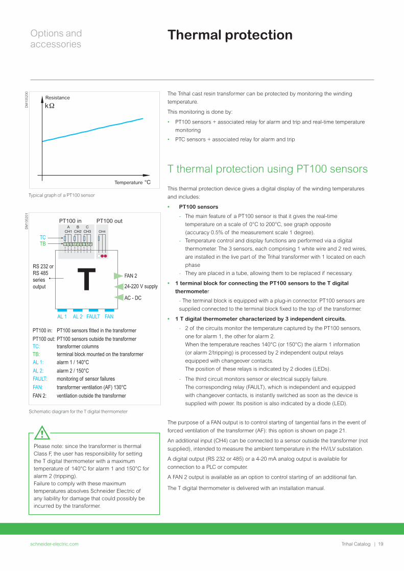
Options and accessories
schneider-electriccom24 | Trihal Catalog
The IP and IK protective indices refer to the following criteria
IP protection indicesFirst Figure Second Figure
definition protection against solid bodies
protection against liquids
scale 0 to 6 0 to 8
IP 31 protection against solid bodies 25 mm
protects against vertical splashing by water
IP 21 protection againstsolid bodies 12 mm
protects against vertical splashing by water
IP 35 protection against solid bodies 25 mm
protects against water jets from all directions
IP 44 protection against solid bodies 1 mm
protects against water jets from all directions
IK protection indicesdefinition protection against mechanical impact
scale (1) 0 to 10
IK7 protection against mechanical impact lt=2 joules
IK10 protection against mechanical impact lt=20 joules
(1) 0 = no protection
With IP 35 and IP 44 transformers can be installed outdoors
Bracket for HV cables entering the bottom of the enclosureWhere required an HV cable bracket is available as an option to guide and support
cables entering the enclosure from the bottom via a removable screw-on aluminum
plate
Protective enclosure IP31 IK7
Protective EnclosureP
M10
5924
Notes
schneider-electriccom | 25Trihal Catalog
schneider-electriccom26 | Trihal Catalog
Tests and technical information
schneider-electriccom | 27Trihal Catalog
Tests and technical information
Tests 28
C3 Climatic Test 28
E3 Environmental Test 28
Fire Withstand 29
Partial Discharge le 5pC 29
Electrical Test 30
EcoDesign Regulation EU 548-2014 31
Tests and technical information
schneider-electriccom28 | Trihal Catalog
C3 climatic tests Trihal takes climatic testing to a new level
The highest certification described by IEC 60076-11 C2 imposes thermal shock
testing to a maximum of -25degC
Trihal passes the same tests at -50degC ensuring optimal performance even in
extreme climates
Lowest ambient temperatures
bull Operation -50degC
bull Storage -50degC
Benefits
bull Resistance to thermal shock
bull Optimum performance under severe ambient conditions
bull Superior behaviour on load changes
bull Extended service life
E3 environmental testTest conducted in two parts according to standards IEC 60076-11 and
IEC 60076-16
Condensation test
bull 6 hours with 95 humidity (by indirect spraying of water with conductivity of
between 36 and 4 Sm)
bull Induced voltage test
Humidity penetration test
bull 6 days at 50degC with 90 (+-5) humidity
bull Dielectric tests
bull Visual inspection
C2 thermal shock test carried out at -50degC
PM
1026
77
E3 environmental test
PM
1026
78
Tests
The new worldwide quality reference C3E3F1 with partial discharge le 5pC
Tests and technical information
schneider-electriccom | 29Trihal Catalog
Tests
F1 fire withstandThe fire behaviour test is conducted in a specific test chamber according to the
procedure described in standard IEC60076-11
bull 1 tank of ethyl alcohol (sufficient quantity for 20 mins combustion) burns under
the tested coil
bull 1 panel heater in front of the tested coil
bull 1 reflector concentric to the coil is fitted opposite the panel heater
The 2 fire-proof effects of the resin used in Trihal made it
possible to observe
bull Immediate self-extinguishing of Trihal as soon as the flames from the alcohol
tank die down and the panel heater is switched off
bull Absence of halogen products toxic emissions and opaque smoke
Partial discharge le 5pCA partial discharge is the dissipation of energy caused by the build-up of
localized electrical field intensity
These phenomena defined by standard IEC 60270 cause the insulation to
deteriorate progressively and can lead to electrical breakdown
The integrity of the transformer insulation is confirmed during Partial Discharge
Analysis and used as a tool to judge the state of the device and the quality of its
manufacture
As proof of our progress in terms of quality the acceptance criteria applicable to
all new Trihal are now le 10 pC during routine tests or le 5 pC in the case of special
tests ordered by the customer according to standard IEC 60076-11
F1 fire withstand tests
PM
1026
80P
M10
2679
Partial discharge test reports
PM
1026
82
PM
1026
81
Tests and technical information
schneider-electriccom30 | Trihal Catalog
Electrical testsThese tests verify the contractual electrical characteristics They include
Routine tests
These tests are systematically carried out on all Trihal transformers at the end of
manufacturing and are subject to an official test report
They comprise
bull Measurement of characteristics
- winding resistance
- transformation ratio and vector group
- impedance voltage
- load losses
- no-load losses and no-load current
bull Dielectric tests
- applied voltage tests 10 kV as standard in LV
- induced voltage tests at 25 Un
- measurement of partial discharge
Type tests and special tests
On request as per relevant standards
These are carried out on request and at the customerrsquos expense
bull Lightning test
Done as standard for 36 kV insulation level and high keraunic level
bull Short-circuit tests
bull Noise level measurements
bull Others on request
Routine test lab
TestsP
M10
5925
Tests and technical information
schneider-electriccom | 31Trihal Catalog
EcoDesign Regulation EU 548-2014
ecodesign
EcoDesign is a European Union regulation which came into force on 11th June
2014 in the 28 countries of the European Union
This new legislation imposes within the EU the maximum level of losses for
transformers placed on the market or commissioned from 1st July 2015 and
purchased after 11th June 2014
After the date of entry into force manufacturers should not enter into new
framework contracts for transformers with energy efficiency specifications below
the minimum requirements outlined in the regulation
Framework contracts signed before 11th June 2014 can continue until the end date
even with deliveries after 1st July 2015
bull EcoDesign has two major objectives for the Transformer product
bull Reducing electrical losses (1st phase in 20152nd phase in 2021)
bull Clarifying and improving the visibility of indication of performance
bull Harmonization of maximum loss levels in the European Union
bull Efficiency request on medium-power transformers for the first time
The following equipment is affected
bull All transformers exceeding 1 kVA and with voltage higher than 1 kV
bull Oil Distribution and Dry-type transformers (le 3150 kVA) with high voltage
winding above 11 kV and up to 36 kV
bull Medium power and Large power transformers gt 3150 kVA and higher than 36
kV (limited to 10 MVA 36 kV for Dry-type Transformers)
Special transformers are not affected by this regulation (please refer to restriction
list for details)
bull Loss levels to be applied (reference of MV le 24 kV and LV le 11 kV)
bull ODT and CRT not covered by reference transformers
(additional losses allowed compared to standard loss ranges)
Authorized loss levels for Oil Distribution and Dry-type Transformers (le 3150 kVA)
PM
1059
26
Maximum loss levels
Rated power
Tier 1 from 01072015
Tier 2 from 01072021
Pole-mounted 25 50 and 100 kVA AoCk AoBk
160 kVA CoCk+32 Co-10 Ck+32
200 250 and 315 kVA CoCk BoBk
Oil-Immersed transformers
le 1000 kVA AoCkAo-10 Ak
gt 1000 kVA AoBk
Dry-Type transformers
le 630 kVA AoBkAo-10 Ak
gt 630 kVA AoAk
Tests and technical information
schneider-electriccom32 | Trihal Catalog
Eg ODT 630 kVA 33 kV - 410 V max losses to be considered A0+15 - Ck +10
Other requirements Impact on no-load lossescompared to standard losses table
Impact on load lossescompared to standard losses table
MV insulation level le 24 kV
LV insulation level gt 11 kV
10 10
MV insulation level = 36 kV
LV insulation level le 11 kV
15 10
MV insulation level = 36 kV
LV insulation level gt 11 kV
20 15
Dual voltage on MV winding and
85 power limitation on higher MV voltage
No impact No impact
Dual voltage on MV winding and
85 power limitation on higher LV voltage
No impact No impact
Dual voltage on one winding (MV or LV)
and full power on all voltages considered
15 10
Dual voltage on both windings (MV and LV) 20 20
Transformers with tappings for operation while energized
(such as Voltage Regulation Distribution Transformers)
20
(reduced to +10 in 01-07-2021)
5
EcoDesign Regulation EU 548-2014
Notes
schneider-electriccom | 33Trihal Catalog
schneider-electriccom34 | Trihal Catalog
Internet
schneider-electriccom | 35Trihal Catalog
Internet
Transformer selector 36
Total Cost of Ownership (TCO) tool 36
Internet
schneider-electriccom36 | Trihal Catalog
Internet tools
Transformer selector Choosing the right transformer for the job can be a real nightmare This web
selector has ben developed to help you find it more easily
Select your segment function type and voltage range and hey presto Your best-
in-class MV transformer is here
Total Cost of Ownership (TCO)When purchasing a transformer and especially when comparing two different
solutions the right choice is driven by an economic analysis of the equipment
Total Cost of Ownership giving the cost of transformer operation throughout their
life including purchasing operating and maintenance costs
Basically some simplification can be done when comparing two different
transformers with the same technology installation maintenance and
decommissioning will generate the same costs and then be excluded from the
comparison
The calculation has to take into consideration changes in the cost of energy during
the transformer life span The interest rate also has to be considered as stated
below
A pragmatic way to choose the right transformer
httpwwwschneider-electriccomentoolstco-for-transformer
Calculation of the TCO
The simplified calculation formula of the Total Cost of Ownership is as
follows
Total Cost of Ownership =
Purchasing Price + No-Load Losses Cost + Load Losses Cost
With
No-Load Losses Cost NLLC = (1+i)^n -1i(1+i)^n C Time
Load Losses Cost LLC = (1+i)^n -1i(1+i)^n C Time Load factorsup2
Where
i interest rate [year]
n lifetime [years]
C kWh price [USDkWh]
Time number of hours in a year [hyear] = 8760
Load factor average load of the transformer during its life time
Calculate TCO
PrintSave PDF Help FeedbackCompare TCO of Transformers
Product Family (Dry Type Oil immersed orMPTLPT)
DRY TYPE
Payback Period Configuration coherence
Transformer Total Cost of Ownership 136484 190526
Purchase price
Load losses (PK)
Load losses Level
No load losses Level
No load losses (PO)
Maximum LV isulation level
Maximum HV isulation level
Rated Power kVA
kV
kV
W
W
EUR 30000 25000
9000 12000
890
Ak
AAA0
lt=24
lt=11
2100
EUR
Yrs 142
1000
Units Transformer 1 Transformer 2
CompareTCO (2)
VIEW COMPARISON GRAPH
200
150
100
50
00 5
142
10
Time of use (yrs)
TR 2
TR 1
Tota
l Cos
t of
Ow
ners
hip
(k)
(E
UR
)
15 20
PM
1059
27P
M10
5928
schneider-electriccom | 37Trihal Catalog
This international web site allows you to access all the Schneider Electric solutions and product information viabull Comprehensive descriptionsbull Range datasheetsbull A download areabull Product selectors
You can also access information dedicated to your business and contact your Schneider Electric country support
PM
1036
87
TOOLS
schneider-electriccom38 | Trihal Catalog
Web selector
Training
This site allows you to access the Schneider Electric products in just two clicks via a comprehensive range of datasheets with direct links tobull Complete libraries technical documents catalogs
FAQs brochuresbull Selection guides from the e-catalogbull Product discovery sites and their animationsYou will also find illustrated overviews news to which you can subscribe and a list of country contacts
Training allows you to acquire the expertise (installation design work with power on etc) to increase efficiency and improve customer service
The training catalog includes beginnerrsquos courses in electrical distribution knowledge of MV and LV switchgear operation and maintenance of installations and design of LV installations to give a few examples
TOOLS
Notes
schneider-electriccom | 39Trihal Catalog
NRJED315663EN
Life
Is
On
Sch
ne
ide
r E
lect
ric
is a
tra
de
ma
rk a
nd
th
e p
rop
ert
y o
f Sch
ne
ide
r E
lect
ric
SE
its
su
bsi
dia
rie
s a
nd
aff
iliat
ed
co
mp
an
ies
All
rig
hts
rese
rve
d
Schneider Electric Industries SAS
35 rue Joseph Monier92500 Rueil-Malmaison FranceTel +33 (0)1 41 29 70 00
wwwschneider-electriccom
SAS capital social 928 298 512 euro 954 503 439 RCS Nanterre
23 08 2016
copy2016 Schneider Electric All Rights ReservedAll trademarks are owned by Schneider Electric Industries SAS or its affiliated companies
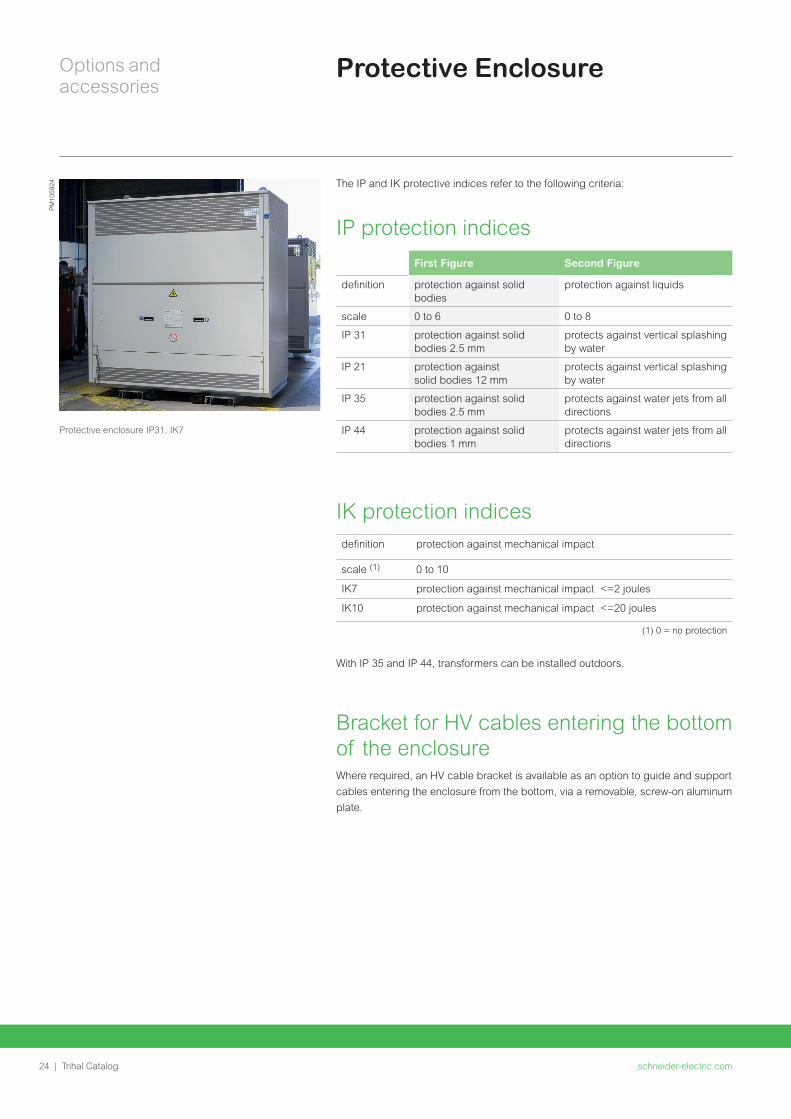
Notes
schneider-electriccom | 25Trihal Catalog
schneider-electriccom26 | Trihal Catalog
Tests and technical information
schneider-electriccom | 27Trihal Catalog
Tests and technical information
Tests 28
C3 Climatic Test 28
E3 Environmental Test 28
Fire Withstand 29
Partial Discharge le 5pC 29
Electrical Test 30
EcoDesign Regulation EU 548-2014 31
Tests and technical information
schneider-electriccom28 | Trihal Catalog
C3 climatic tests Trihal takes climatic testing to a new level
The highest certification described by IEC 60076-11 C2 imposes thermal shock
testing to a maximum of -25degC
Trihal passes the same tests at -50degC ensuring optimal performance even in
extreme climates
Lowest ambient temperatures
bull Operation -50degC
bull Storage -50degC
Benefits
bull Resistance to thermal shock
bull Optimum performance under severe ambient conditions
bull Superior behaviour on load changes
bull Extended service life
E3 environmental testTest conducted in two parts according to standards IEC 60076-11 and
IEC 60076-16
Condensation test
bull 6 hours with 95 humidity (by indirect spraying of water with conductivity of
between 36 and 4 Sm)
bull Induced voltage test
Humidity penetration test
bull 6 days at 50degC with 90 (+-5) humidity
bull Dielectric tests
bull Visual inspection
C2 thermal shock test carried out at -50degC
PM
1026
77
E3 environmental test
PM
1026
78
Tests
The new worldwide quality reference C3E3F1 with partial discharge le 5pC
Tests and technical information
schneider-electriccom | 29Trihal Catalog
Tests
F1 fire withstandThe fire behaviour test is conducted in a specific test chamber according to the
procedure described in standard IEC60076-11
bull 1 tank of ethyl alcohol (sufficient quantity for 20 mins combustion) burns under
the tested coil
bull 1 panel heater in front of the tested coil
bull 1 reflector concentric to the coil is fitted opposite the panel heater
The 2 fire-proof effects of the resin used in Trihal made it
possible to observe
bull Immediate self-extinguishing of Trihal as soon as the flames from the alcohol
tank die down and the panel heater is switched off
bull Absence of halogen products toxic emissions and opaque smoke
Partial discharge le 5pCA partial discharge is the dissipation of energy caused by the build-up of
localized electrical field intensity
These phenomena defined by standard IEC 60270 cause the insulation to
deteriorate progressively and can lead to electrical breakdown
The integrity of the transformer insulation is confirmed during Partial Discharge
Analysis and used as a tool to judge the state of the device and the quality of its
manufacture
As proof of our progress in terms of quality the acceptance criteria applicable to
all new Trihal are now le 10 pC during routine tests or le 5 pC in the case of special
tests ordered by the customer according to standard IEC 60076-11
F1 fire withstand tests
PM
1026
80P
M10
2679
Partial discharge test reports
PM
1026
82
PM
1026
81
Tests and technical information
schneider-electriccom30 | Trihal Catalog
Electrical testsThese tests verify the contractual electrical characteristics They include
Routine tests
These tests are systematically carried out on all Trihal transformers at the end of
manufacturing and are subject to an official test report
They comprise
bull Measurement of characteristics
- winding resistance
- transformation ratio and vector group
- impedance voltage
- load losses
- no-load losses and no-load current
bull Dielectric tests
- applied voltage tests 10 kV as standard in LV
- induced voltage tests at 25 Un
- measurement of partial discharge
Type tests and special tests
On request as per relevant standards
These are carried out on request and at the customerrsquos expense
bull Lightning test
Done as standard for 36 kV insulation level and high keraunic level
bull Short-circuit tests
bull Noise level measurements
bull Others on request
Routine test lab
TestsP
M10
5925
Tests and technical information
schneider-electriccom | 31Trihal Catalog
EcoDesign Regulation EU 548-2014
ecodesign
EcoDesign is a European Union regulation which came into force on 11th June
2014 in the 28 countries of the European Union
This new legislation imposes within the EU the maximum level of losses for
transformers placed on the market or commissioned from 1st July 2015 and
purchased after 11th June 2014
After the date of entry into force manufacturers should not enter into new
framework contracts for transformers with energy efficiency specifications below
the minimum requirements outlined in the regulation
Framework contracts signed before 11th June 2014 can continue until the end date
even with deliveries after 1st July 2015
bull EcoDesign has two major objectives for the Transformer product
bull Reducing electrical losses (1st phase in 20152nd phase in 2021)
bull Clarifying and improving the visibility of indication of performance
bull Harmonization of maximum loss levels in the European Union
bull Efficiency request on medium-power transformers for the first time
The following equipment is affected
bull All transformers exceeding 1 kVA and with voltage higher than 1 kV
bull Oil Distribution and Dry-type transformers (le 3150 kVA) with high voltage
winding above 11 kV and up to 36 kV
bull Medium power and Large power transformers gt 3150 kVA and higher than 36
kV (limited to 10 MVA 36 kV for Dry-type Transformers)
Special transformers are not affected by this regulation (please refer to restriction
list for details)
bull Loss levels to be applied (reference of MV le 24 kV and LV le 11 kV)
bull ODT and CRT not covered by reference transformers
(additional losses allowed compared to standard loss ranges)
Authorized loss levels for Oil Distribution and Dry-type Transformers (le 3150 kVA)
PM
1059
26
Maximum loss levels
Rated power
Tier 1 from 01072015
Tier 2 from 01072021
Pole-mounted 25 50 and 100 kVA AoCk AoBk
160 kVA CoCk+32 Co-10 Ck+32
200 250 and 315 kVA CoCk BoBk
Oil-Immersed transformers
le 1000 kVA AoCkAo-10 Ak
gt 1000 kVA AoBk
Dry-Type transformers
le 630 kVA AoBkAo-10 Ak
gt 630 kVA AoAk
Tests and technical information
schneider-electriccom32 | Trihal Catalog
Eg ODT 630 kVA 33 kV - 410 V max losses to be considered A0+15 - Ck +10
Other requirements Impact on no-load lossescompared to standard losses table
Impact on load lossescompared to standard losses table
MV insulation level le 24 kV
LV insulation level gt 11 kV
10 10
MV insulation level = 36 kV
LV insulation level le 11 kV
15 10
MV insulation level = 36 kV
LV insulation level gt 11 kV
20 15
Dual voltage on MV winding and
85 power limitation on higher MV voltage
No impact No impact
Dual voltage on MV winding and
85 power limitation on higher LV voltage
No impact No impact
Dual voltage on one winding (MV or LV)
and full power on all voltages considered
15 10
Dual voltage on both windings (MV and LV) 20 20
Transformers with tappings for operation while energized
(such as Voltage Regulation Distribution Transformers)
20
(reduced to +10 in 01-07-2021)
5
EcoDesign Regulation EU 548-2014
Notes
schneider-electriccom | 33Trihal Catalog
schneider-electriccom34 | Trihal Catalog
Internet
schneider-electriccom | 35Trihal Catalog
Internet
Transformer selector 36
Total Cost of Ownership (TCO) tool 36
Internet
schneider-electriccom36 | Trihal Catalog
Internet tools
Transformer selector Choosing the right transformer for the job can be a real nightmare This web
selector has ben developed to help you find it more easily
Select your segment function type and voltage range and hey presto Your best-
in-class MV transformer is here
Total Cost of Ownership (TCO)When purchasing a transformer and especially when comparing two different
solutions the right choice is driven by an economic analysis of the equipment
Total Cost of Ownership giving the cost of transformer operation throughout their
life including purchasing operating and maintenance costs
Basically some simplification can be done when comparing two different
transformers with the same technology installation maintenance and
decommissioning will generate the same costs and then be excluded from the
comparison
The calculation has to take into consideration changes in the cost of energy during
the transformer life span The interest rate also has to be considered as stated
below
A pragmatic way to choose the right transformer
httpwwwschneider-electriccomentoolstco-for-transformer
Calculation of the TCO
The simplified calculation formula of the Total Cost of Ownership is as
follows
Total Cost of Ownership =
Purchasing Price + No-Load Losses Cost + Load Losses Cost
With
No-Load Losses Cost NLLC = (1+i)^n -1i(1+i)^n C Time
Load Losses Cost LLC = (1+i)^n -1i(1+i)^n C Time Load factorsup2
Where
i interest rate [year]
n lifetime [years]
C kWh price [USDkWh]
Time number of hours in a year [hyear] = 8760
Load factor average load of the transformer during its life time
Calculate TCO
PrintSave PDF Help FeedbackCompare TCO of Transformers
Product Family (Dry Type Oil immersed orMPTLPT)
DRY TYPE
Payback Period Configuration coherence
Transformer Total Cost of Ownership 136484 190526
Purchase price
Load losses (PK)
Load losses Level
No load losses Level
No load losses (PO)
Maximum LV isulation level
Maximum HV isulation level
Rated Power kVA
kV
kV
W
W
EUR 30000 25000
9000 12000
890
Ak
AAA0
lt=24
lt=11
2100
EUR
Yrs 142
1000
Units Transformer 1 Transformer 2
CompareTCO (2)
VIEW COMPARISON GRAPH
200
150
100
50
00 5
142
10
Time of use (yrs)
TR 2
TR 1
Tota
l Cos
t of
Ow
ners
hip
(k)
(E
UR
)
15 20
PM
1059
27P
M10
5928
schneider-electriccom | 37Trihal Catalog
This international web site allows you to access all the Schneider Electric solutions and product information viabull Comprehensive descriptionsbull Range datasheetsbull A download areabull Product selectors
You can also access information dedicated to your business and contact your Schneider Electric country support
PM
1036
87
TOOLS
schneider-electriccom38 | Trihal Catalog
Web selector
Training
This site allows you to access the Schneider Electric products in just two clicks via a comprehensive range of datasheets with direct links tobull Complete libraries technical documents catalogs
FAQs brochuresbull Selection guides from the e-catalogbull Product discovery sites and their animationsYou will also find illustrated overviews news to which you can subscribe and a list of country contacts
Training allows you to acquire the expertise (installation design work with power on etc) to increase efficiency and improve customer service
The training catalog includes beginnerrsquos courses in electrical distribution knowledge of MV and LV switchgear operation and maintenance of installations and design of LV installations to give a few examples
TOOLS
Notes
schneider-electriccom | 39Trihal Catalog
NRJED315663EN
Life
Is
On
Sch
ne
ide
r E
lect
ric
is a
tra
de
ma
rk a
nd
th
e p
rop
ert
y o
f Sch
ne
ide
r E
lect
ric
SE
its
su
bsi
dia
rie
s a
nd
aff
iliat
ed
co
mp
an
ies
All
rig
hts
rese
rve
d
Schneider Electric Industries SAS
35 rue Joseph Monier92500 Rueil-Malmaison FranceTel +33 (0)1 41 29 70 00
wwwschneider-electriccom
SAS capital social 928 298 512 euro 954 503 439 RCS Nanterre
23 08 2016
copy2016 Schneider Electric All Rights ReservedAll trademarks are owned by Schneider Electric Industries SAS or its affiliated companies

Tests and technical information
schneider-electriccom28 | Trihal Catalog
C3 climatic tests Trihal takes climatic testing to a new level
The highest certification described by IEC 60076-11 C2 imposes thermal shock
testing to a maximum of -25degC
Trihal passes the same tests at -50degC ensuring optimal performance even in
extreme climates
Lowest ambient temperatures
bull Operation -50degC
bull Storage -50degC
Benefits
bull Resistance to thermal shock
bull Optimum performance under severe ambient conditions
bull Superior behaviour on load changes
bull Extended service life
E3 environmental testTest conducted in two parts according to standards IEC 60076-11 and
IEC 60076-16
Condensation test
bull 6 hours with 95 humidity (by indirect spraying of water with conductivity of
between 36 and 4 Sm)
bull Induced voltage test
Humidity penetration test
bull 6 days at 50degC with 90 (+-5) humidity
bull Dielectric tests
bull Visual inspection
C2 thermal shock test carried out at -50degC
PM
1026
77
E3 environmental test
PM
1026
78
Tests
The new worldwide quality reference C3E3F1 with partial discharge le 5pC
Tests and technical information
schneider-electriccom | 29Trihal Catalog
Tests
F1 fire withstandThe fire behaviour test is conducted in a specific test chamber according to the
procedure described in standard IEC60076-11
bull 1 tank of ethyl alcohol (sufficient quantity for 20 mins combustion) burns under
the tested coil
bull 1 panel heater in front of the tested coil
bull 1 reflector concentric to the coil is fitted opposite the panel heater
The 2 fire-proof effects of the resin used in Trihal made it
possible to observe
bull Immediate self-extinguishing of Trihal as soon as the flames from the alcohol
tank die down and the panel heater is switched off
bull Absence of halogen products toxic emissions and opaque smoke
Partial discharge le 5pCA partial discharge is the dissipation of energy caused by the build-up of
localized electrical field intensity
These phenomena defined by standard IEC 60270 cause the insulation to
deteriorate progressively and can lead to electrical breakdown
The integrity of the transformer insulation is confirmed during Partial Discharge
Analysis and used as a tool to judge the state of the device and the quality of its
manufacture
As proof of our progress in terms of quality the acceptance criteria applicable to
all new Trihal are now le 10 pC during routine tests or le 5 pC in the case of special
tests ordered by the customer according to standard IEC 60076-11
F1 fire withstand tests
PM
1026
80P
M10
2679
Partial discharge test reports
PM
1026
82
PM
1026
81
Tests and technical information
schneider-electriccom30 | Trihal Catalog
Electrical testsThese tests verify the contractual electrical characteristics They include
Routine tests
These tests are systematically carried out on all Trihal transformers at the end of
manufacturing and are subject to an official test report
They comprise
bull Measurement of characteristics
- winding resistance
- transformation ratio and vector group
- impedance voltage
- load losses
- no-load losses and no-load current
bull Dielectric tests
- applied voltage tests 10 kV as standard in LV
- induced voltage tests at 25 Un
- measurement of partial discharge
Type tests and special tests
On request as per relevant standards
These are carried out on request and at the customerrsquos expense
bull Lightning test
Done as standard for 36 kV insulation level and high keraunic level
bull Short-circuit tests
bull Noise level measurements
bull Others on request
Routine test lab
TestsP
M10
5925
Tests and technical information
schneider-electriccom | 31Trihal Catalog
EcoDesign Regulation EU 548-2014
ecodesign
EcoDesign is a European Union regulation which came into force on 11th June
2014 in the 28 countries of the European Union
This new legislation imposes within the EU the maximum level of losses for
transformers placed on the market or commissioned from 1st July 2015 and
purchased after 11th June 2014
After the date of entry into force manufacturers should not enter into new
framework contracts for transformers with energy efficiency specifications below
the minimum requirements outlined in the regulation
Framework contracts signed before 11th June 2014 can continue until the end date
even with deliveries after 1st July 2015
bull EcoDesign has two major objectives for the Transformer product
bull Reducing electrical losses (1st phase in 20152nd phase in 2021)
bull Clarifying and improving the visibility of indication of performance
bull Harmonization of maximum loss levels in the European Union
bull Efficiency request on medium-power transformers for the first time
The following equipment is affected
bull All transformers exceeding 1 kVA and with voltage higher than 1 kV
bull Oil Distribution and Dry-type transformers (le 3150 kVA) with high voltage
winding above 11 kV and up to 36 kV
bull Medium power and Large power transformers gt 3150 kVA and higher than 36
kV (limited to 10 MVA 36 kV for Dry-type Transformers)
Special transformers are not affected by this regulation (please refer to restriction
list for details)
bull Loss levels to be applied (reference of MV le 24 kV and LV le 11 kV)
bull ODT and CRT not covered by reference transformers
(additional losses allowed compared to standard loss ranges)
Authorized loss levels for Oil Distribution and Dry-type Transformers (le 3150 kVA)
PM
1059
26
Maximum loss levels
Rated power
Tier 1 from 01072015
Tier 2 from 01072021
Pole-mounted 25 50 and 100 kVA AoCk AoBk
160 kVA CoCk+32 Co-10 Ck+32
200 250 and 315 kVA CoCk BoBk
Oil-Immersed transformers
le 1000 kVA AoCkAo-10 Ak
gt 1000 kVA AoBk
Dry-Type transformers
le 630 kVA AoBkAo-10 Ak
gt 630 kVA AoAk
Tests and technical information
schneider-electriccom32 | Trihal Catalog
Eg ODT 630 kVA 33 kV - 410 V max losses to be considered A0+15 - Ck +10
Other requirements Impact on no-load lossescompared to standard losses table
Impact on load lossescompared to standard losses table
MV insulation level le 24 kV
LV insulation level gt 11 kV
10 10
MV insulation level = 36 kV
LV insulation level le 11 kV
15 10
MV insulation level = 36 kV
LV insulation level gt 11 kV
20 15
Dual voltage on MV winding and
85 power limitation on higher MV voltage
No impact No impact
Dual voltage on MV winding and
85 power limitation on higher LV voltage
No impact No impact
Dual voltage on one winding (MV or LV)
and full power on all voltages considered
15 10
Dual voltage on both windings (MV and LV) 20 20
Transformers with tappings for operation while energized
(such as Voltage Regulation Distribution Transformers)
20
(reduced to +10 in 01-07-2021)
5
EcoDesign Regulation EU 548-2014
Notes
schneider-electriccom | 33Trihal Catalog
schneider-electriccom34 | Trihal Catalog
Internet
schneider-electriccom | 35Trihal Catalog
Internet
Transformer selector 36
Total Cost of Ownership (TCO) tool 36
Internet
schneider-electriccom36 | Trihal Catalog
Internet tools
Transformer selector Choosing the right transformer for the job can be a real nightmare This web
selector has ben developed to help you find it more easily
Select your segment function type and voltage range and hey presto Your best-
in-class MV transformer is here
Total Cost of Ownership (TCO)When purchasing a transformer and especially when comparing two different
solutions the right choice is driven by an economic analysis of the equipment
Total Cost of Ownership giving the cost of transformer operation throughout their
life including purchasing operating and maintenance costs
Basically some simplification can be done when comparing two different
transformers with the same technology installation maintenance and
decommissioning will generate the same costs and then be excluded from the
comparison
The calculation has to take into consideration changes in the cost of energy during
the transformer life span The interest rate also has to be considered as stated
below
A pragmatic way to choose the right transformer
httpwwwschneider-electriccomentoolstco-for-transformer
Calculation of the TCO
The simplified calculation formula of the Total Cost of Ownership is as
follows
Total Cost of Ownership =
Purchasing Price + No-Load Losses Cost + Load Losses Cost
With
No-Load Losses Cost NLLC = (1+i)^n -1i(1+i)^n C Time
Load Losses Cost LLC = (1+i)^n -1i(1+i)^n C Time Load factorsup2
Where
i interest rate [year]
n lifetime [years]
C kWh price [USDkWh]
Time number of hours in a year [hyear] = 8760
Load factor average load of the transformer during its life time
Calculate TCO
PrintSave PDF Help FeedbackCompare TCO of Transformers
Product Family (Dry Type Oil immersed orMPTLPT)
DRY TYPE
Payback Period Configuration coherence
Transformer Total Cost of Ownership 136484 190526
Purchase price
Load losses (PK)
Load losses Level
No load losses Level
No load losses (PO)
Maximum LV isulation level
Maximum HV isulation level
Rated Power kVA
kV
kV
W
W
EUR 30000 25000
9000 12000
890
Ak
AAA0
lt=24
lt=11
2100
EUR
Yrs 142
1000
Units Transformer 1 Transformer 2
CompareTCO (2)
VIEW COMPARISON GRAPH
200
150
100
50
00 5
142
10
Time of use (yrs)
TR 2
TR 1
Tota
l Cos
t of
Ow
ners
hip
(k)
(E
UR
)
15 20
PM
1059
27P
M10
5928
schneider-electriccom | 37Trihal Catalog
This international web site allows you to access all the Schneider Electric solutions and product information viabull Comprehensive descriptionsbull Range datasheetsbull A download areabull Product selectors
You can also access information dedicated to your business and contact your Schneider Electric country support
PM
1036
87
TOOLS
schneider-electriccom38 | Trihal Catalog
Web selector
Training
This site allows you to access the Schneider Electric products in just two clicks via a comprehensive range of datasheets with direct links tobull Complete libraries technical documents catalogs
FAQs brochuresbull Selection guides from the e-catalogbull Product discovery sites and their animationsYou will also find illustrated overviews news to which you can subscribe and a list of country contacts
Training allows you to acquire the expertise (installation design work with power on etc) to increase efficiency and improve customer service
The training catalog includes beginnerrsquos courses in electrical distribution knowledge of MV and LV switchgear operation and maintenance of installations and design of LV installations to give a few examples
TOOLS
Notes
schneider-electriccom | 39Trihal Catalog
NRJED315663EN
Life
Is
On
Sch
ne
ide
r E
lect
ric
is a
tra
de
ma
rk a
nd
th
e p
rop
ert
y o
f Sch
ne
ide
r E
lect
ric
SE
its
su
bsi
dia
rie
s a
nd
aff
iliat
ed
co
mp
an
ies
All
rig
hts
rese
rve
d
Schneider Electric Industries SAS
35 rue Joseph Monier92500 Rueil-Malmaison FranceTel +33 (0)1 41 29 70 00
wwwschneider-electriccom
SAS capital social 928 298 512 euro 954 503 439 RCS Nanterre
23 08 2016
copy2016 Schneider Electric All Rights ReservedAll trademarks are owned by Schneider Electric Industries SAS or its affiliated companies
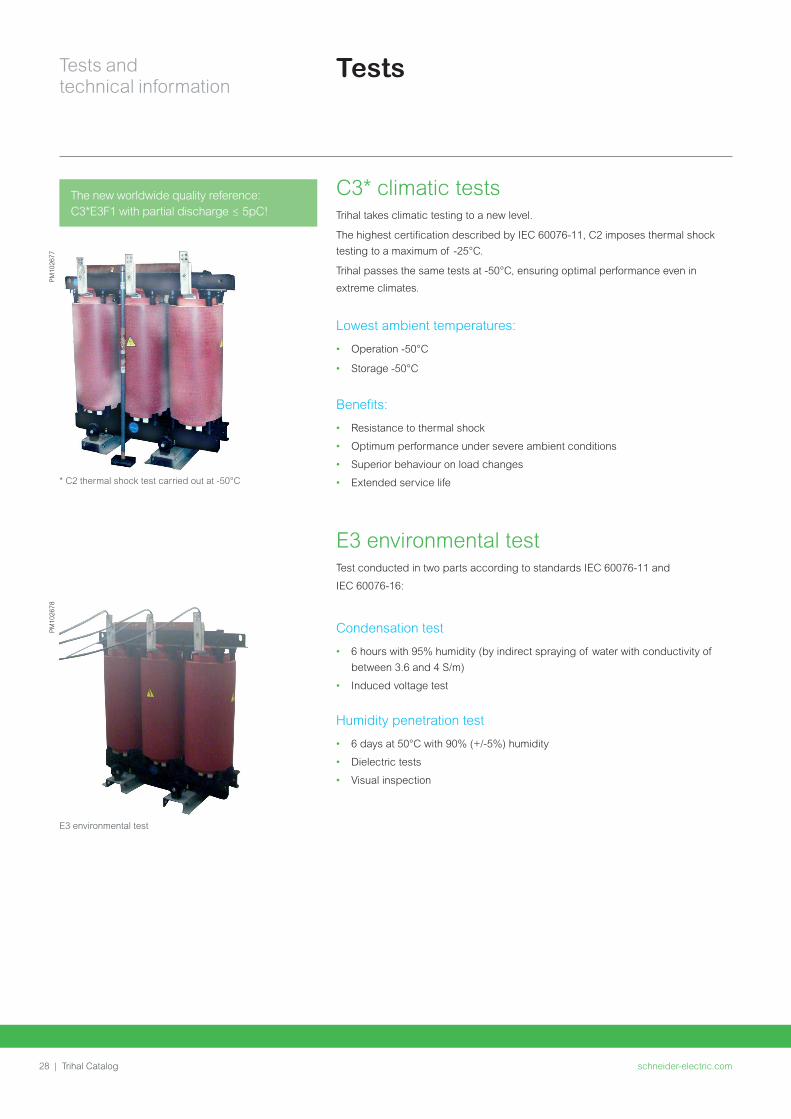
Tests and technical information
schneider-electriccom32 | Trihal Catalog
Eg ODT 630 kVA 33 kV - 410 V max losses to be considered A0+15 - Ck +10
Other requirements Impact on no-load lossescompared to standard losses table
Impact on load lossescompared to standard losses table
MV insulation level le 24 kV
LV insulation level gt 11 kV
10 10
MV insulation level = 36 kV
LV insulation level le 11 kV
15 10
MV insulation level = 36 kV
LV insulation level gt 11 kV
20 15
Dual voltage on MV winding and
85 power limitation on higher MV voltage
No impact No impact
Dual voltage on MV winding and
85 power limitation on higher LV voltage
No impact No impact
Dual voltage on one winding (MV or LV)
and full power on all voltages considered
15 10
Dual voltage on both windings (MV and LV) 20 20
Transformers with tappings for operation while energized
(such as Voltage Regulation Distribution Transformers)
20
(reduced to +10 in 01-07-2021)
5
EcoDesign Regulation EU 548-2014
Notes
schneider-electriccom | 33Trihal Catalog
schneider-electriccom34 | Trihal Catalog
Internet
schneider-electriccom | 35Trihal Catalog
Internet
Transformer selector 36
Total Cost of Ownership (TCO) tool 36
Internet
schneider-electriccom36 | Trihal Catalog
Internet tools
Transformer selector Choosing the right transformer for the job can be a real nightmare This web
selector has ben developed to help you find it more easily
Select your segment function type and voltage range and hey presto Your best-
in-class MV transformer is here
Total Cost of Ownership (TCO)When purchasing a transformer and especially when comparing two different
solutions the right choice is driven by an economic analysis of the equipment
Total Cost of Ownership giving the cost of transformer operation throughout their
life including purchasing operating and maintenance costs
Basically some simplification can be done when comparing two different
transformers with the same technology installation maintenance and
decommissioning will generate the same costs and then be excluded from the
comparison
The calculation has to take into consideration changes in the cost of energy during
the transformer life span The interest rate also has to be considered as stated
below
A pragmatic way to choose the right transformer
httpwwwschneider-electriccomentoolstco-for-transformer
Calculation of the TCO
The simplified calculation formula of the Total Cost of Ownership is as
follows
Total Cost of Ownership =
Purchasing Price + No-Load Losses Cost + Load Losses Cost
With
No-Load Losses Cost NLLC = (1+i)^n -1i(1+i)^n C Time
Load Losses Cost LLC = (1+i)^n -1i(1+i)^n C Time Load factorsup2
Where
i interest rate [year]
n lifetime [years]
C kWh price [USDkWh]
Time number of hours in a year [hyear] = 8760
Load factor average load of the transformer during its life time
Calculate TCO
PrintSave PDF Help FeedbackCompare TCO of Transformers
Product Family (Dry Type Oil immersed orMPTLPT)
DRY TYPE
Payback Period Configuration coherence
Transformer Total Cost of Ownership 136484 190526
Purchase price
Load losses (PK)
Load losses Level
No load losses Level
No load losses (PO)
Maximum LV isulation level
Maximum HV isulation level
Rated Power kVA
kV
kV
W
W
EUR 30000 25000
9000 12000
890
Ak
AAA0
lt=24
lt=11
2100
EUR
Yrs 142
1000
Units Transformer 1 Transformer 2
CompareTCO (2)
VIEW COMPARISON GRAPH
200
150
100
50
00 5
142
10
Time of use (yrs)
TR 2
TR 1
Tota
l Cos
t of
Ow
ners
hip
(k)
(E
UR
)
15 20
PM
1059
27P
M10
5928
schneider-electriccom | 37Trihal Catalog
This international web site allows you to access all the Schneider Electric solutions and product information viabull Comprehensive descriptionsbull Range datasheetsbull A download areabull Product selectors
You can also access information dedicated to your business and contact your Schneider Electric country support
PM
1036
87
TOOLS
schneider-electriccom38 | Trihal Catalog
Web selector
Training
This site allows you to access the Schneider Electric products in just two clicks via a comprehensive range of datasheets with direct links tobull Complete libraries technical documents catalogs
FAQs brochuresbull Selection guides from the e-catalogbull Product discovery sites and their animationsYou will also find illustrated overviews news to which you can subscribe and a list of country contacts
Training allows you to acquire the expertise (installation design work with power on etc) to increase efficiency and improve customer service
The training catalog includes beginnerrsquos courses in electrical distribution knowledge of MV and LV switchgear operation and maintenance of installations and design of LV installations to give a few examples
TOOLS
Notes
schneider-electriccom | 39Trihal Catalog
NRJED315663EN
Life
Is
On
Sch
ne
ide
r E
lect
ric
is a
tra
de
ma
rk a
nd
th
e p
rop
ert
y o
f Sch
ne
ide
r E
lect
ric
SE
its
su
bsi
dia
rie
s a
nd
aff
iliat
ed
co
mp
an
ies
All
rig
hts
rese
rve
d
Schneider Electric Industries SAS
35 rue Joseph Monier92500 Rueil-Malmaison FranceTel +33 (0)1 41 29 70 00
wwwschneider-electriccom
SAS capital social 928 298 512 euro 954 503 439 RCS Nanterre
23 08 2016
copy2016 Schneider Electric All Rights ReservedAll trademarks are owned by Schneider Electric Industries SAS or its affiliated companies
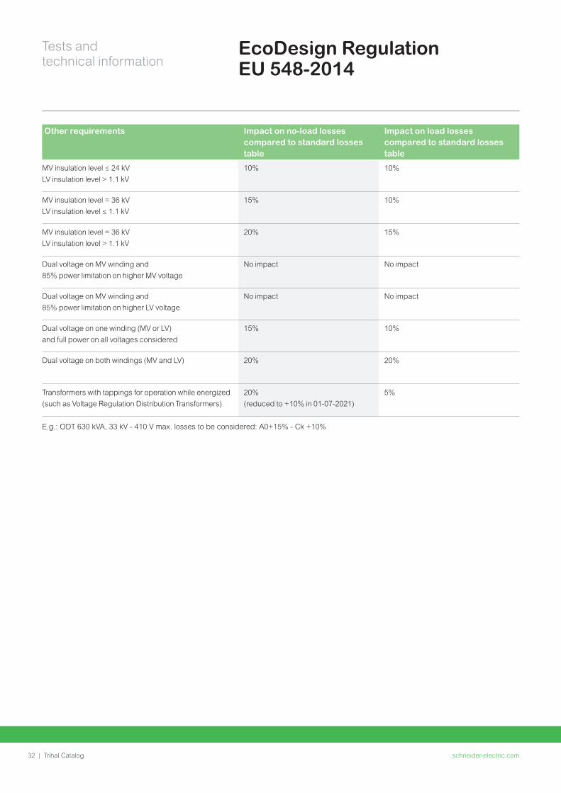
Notes
schneider-electriccom | 33Trihal Catalog
schneider-electriccom34 | Trihal Catalog
Internet
schneider-electriccom | 35Trihal Catalog
Internet
Transformer selector 36
Total Cost of Ownership (TCO) tool 36
Internet
schneider-electriccom36 | Trihal Catalog
Internet tools
Transformer selector Choosing the right transformer for the job can be a real nightmare This web
selector has ben developed to help you find it more easily
Select your segment function type and voltage range and hey presto Your best-
in-class MV transformer is here
Total Cost of Ownership (TCO)When purchasing a transformer and especially when comparing two different
solutions the right choice is driven by an economic analysis of the equipment
Total Cost of Ownership giving the cost of transformer operation throughout their
life including purchasing operating and maintenance costs
Basically some simplification can be done when comparing two different
transformers with the same technology installation maintenance and
decommissioning will generate the same costs and then be excluded from the
comparison
The calculation has to take into consideration changes in the cost of energy during
the transformer life span The interest rate also has to be considered as stated
below
A pragmatic way to choose the right transformer
httpwwwschneider-electriccomentoolstco-for-transformer
Calculation of the TCO
The simplified calculation formula of the Total Cost of Ownership is as
follows
Total Cost of Ownership =
Purchasing Price + No-Load Losses Cost + Load Losses Cost
With
No-Load Losses Cost NLLC = (1+i)^n -1i(1+i)^n C Time
Load Losses Cost LLC = (1+i)^n -1i(1+i)^n C Time Load factorsup2
Where
i interest rate [year]
n lifetime [years]
C kWh price [USDkWh]
Time number of hours in a year [hyear] = 8760
Load factor average load of the transformer during its life time
Calculate TCO
PrintSave PDF Help FeedbackCompare TCO of Transformers
Product Family (Dry Type Oil immersed orMPTLPT)
DRY TYPE
Payback Period Configuration coherence
Transformer Total Cost of Ownership 136484 190526
Purchase price
Load losses (PK)
Load losses Level
No load losses Level
No load losses (PO)
Maximum LV isulation level
Maximum HV isulation level
Rated Power kVA
kV
kV
W
W
EUR 30000 25000
9000 12000
890
Ak
AAA0
lt=24
lt=11
2100
EUR
Yrs 142
1000
Units Transformer 1 Transformer 2
CompareTCO (2)
VIEW COMPARISON GRAPH
200
150
100
50
00 5
142
10
Time of use (yrs)
TR 2
TR 1
Tota
l Cos
t of
Ow
ners
hip
(k)
(E
UR
)
15 20
PM
1059
27P
M10
5928
schneider-electriccom | 37Trihal Catalog
This international web site allows you to access all the Schneider Electric solutions and product information viabull Comprehensive descriptionsbull Range datasheetsbull A download areabull Product selectors
You can also access information dedicated to your business and contact your Schneider Electric country support
PM
1036
87
TOOLS
schneider-electriccom38 | Trihal Catalog
Web selector
Training
This site allows you to access the Schneider Electric products in just two clicks via a comprehensive range of datasheets with direct links tobull Complete libraries technical documents catalogs
FAQs brochuresbull Selection guides from the e-catalogbull Product discovery sites and their animationsYou will also find illustrated overviews news to which you can subscribe and a list of country contacts
Training allows you to acquire the expertise (installation design work with power on etc) to increase efficiency and improve customer service
The training catalog includes beginnerrsquos courses in electrical distribution knowledge of MV and LV switchgear operation and maintenance of installations and design of LV installations to give a few examples
TOOLS
Notes
schneider-electriccom | 39Trihal Catalog
NRJED315663EN
Life
Is
On
Sch
ne
ide
r E
lect
ric
is a
tra
de
ma
rk a
nd
th
e p
rop
ert
y o
f Sch
ne
ide
r E
lect
ric
SE
its
su
bsi
dia
rie
s a
nd
aff
iliat
ed
co
mp
an
ies
All
rig
hts
rese
rve
d
Schneider Electric Industries SAS
35 rue Joseph Monier92500 Rueil-Malmaison FranceTel +33 (0)1 41 29 70 00
wwwschneider-electriccom
SAS capital social 928 298 512 euro 954 503 439 RCS Nanterre
23 08 2016
copy2016 Schneider Electric All Rights ReservedAll trademarks are owned by Schneider Electric Industries SAS or its affiliated companies